Anisotropy in Mechanical Properties and Fracture Behavior of an Oxide Dispersion Fe20Cr5Al Alloy
J.CHAO and C.CAPDEVILA
Anisotropy of fracture toughness and fracture behavior of Fe20Cr5Al oxide dispersion-
strengthened alloy has been investigated by means of compression tests,hardness tests,and
wedge splitting test.The results show a small e?ect of the compression direction on yield
strength(YS)and strain hardening.The YS is minimum for longitudinal direction and maxi-
mum for the tangential direction.The transverse plastic strain ratio is similar for tangential and
longitudinal directions but very di?erent from that in normal direction.Hardness depends on
the indentation plane;it is lower for any plane parallel to the L-T plane and of similar mag-
nitude for the other orthogonal planes,i.e.,the L-S and T-S planes.Macroscopically,two failure
modes have been observed after wedge-splitting tests,those of LS and TS specimens in which
fracture deviates along one or two branches normal to the notch plane,and those of LT,TL,
SL,and ST specimens in which fracture propagates along the notch plane.Besides LT and TL
specimens present delaminations parallel to L-T plane.Both,the fracture surface of branching
cracks and that of the delaminations,show an intergranular brittle fracture appearance.It is
proposed that the main cause of the delamination and crack branching is the alignment in the
mesoscopic scale of the ultra?ne grains structure which is enhanced by the h110i-texture of the
material and by the presence in the grain boundaries of both yttria dispersoids and impurity
contaminations.An elastoplastic?nite element analysis was performed to study what stress state
is the cause of the branches and delaminations.It is concluded that the normal to the crack
branches and/or the shear stress components could determine the crack bifurcation mechanism,
whereas the delamination it seems that it is controlled by the magnitude of the stress component
normal to the delamination plane.
DOI:10.1007/s11661-014-2329-7
óThe Minerals,Metals&Materials Society and ASM International2014
I.INTRODUCTION
O XIDE dispersion-strengthened(ODS)ferritic stain-less steels are considered the most promising structural materials for several types of reactors,including future fusion reactors,since it combines an acceptable creep rupture strength,excellent swelling resistance,and high corrosion resistance in supercritical pressurized water.[1] These materials are usually produced by mechanical alloying(MA)of yttria nano-particles and pre-alloyed or elementary powders of Fe,Cr,Al,and Ti elements.[2] The resulting powders are vulnerable to impurity contamination due to the MA processing.The consol-idation of the powders is performed by hot isostatic pressing and/or hot extrusion at about1273K to 1373K(1000°C to1100°C).[2]These thermomechan-ical processes led to the development of a bundle-like structure of elongated grains with isolated submicro-metric particles stringers aligned with the extrusion/ rolling direction.Moreover,a strong h110i?ber texture along extrusion/rolling direction is formed.Lower fracture toughness than conventional ferritic steel is one of the important factors limiting the use of ODS steels in the nuclear power industry.It is generally thought that MA of ferritic steels with Y2O3particles is the cause of the degradation of the impact behavior of the steel.[3]Another issue linked to the ODS steels is their pronounced anisotropic behavior in tensile elon-gation and ductile–brittle transition behavior coming from the fabrication route.[4]It was suggested that the anisotropy of mechanical properties could be explained not by the texture but by the combined e?ect of the above described structure and segregation/precipitation/ inclusion of titanium.[5]However,it was recently reported that the anisotropy of toughness is determined by three factors:distribution in size and shape of inclusions,microstructural anisotropy due to banding, and crystallographic texture.[6]The anisotropy of tough-ness is a complex mechanical phenomenon that would depend not only on the chemical composition and the matrix microstructure(grain size,dislocations density, crystallographic texture…),but also on the mesoscopic grain morphology and the segregation and inclusion states of the alloy.
The objective of the present work is to characterize the mechanical and fracture behavior as a function of specimen orientation in a hot extruded tube.The mechanical behavior(yield strength,strain hardening and transverse plastic strain ratio)was analyzed by
J.CHAO,Head of Mechanical Testing Laboratory,and C. CAPDEVILA,Physicist,Researcher,are with the Centro Nacional de Investigaciones Metalurgicas(CENIM-CSIC),Avenida Gregorio del Amo8,28040Madrid,Spain.Contact e-mail:jchao@cenim.csic.es Manuscript submitted April15,2013.
Article published online April15,2014
means of compression tests of cube specimens,whereas the fracture behavior was studied by means of wedge splitting test (WST)of notched cube specimens.From the ?nite element analysis of the experimental results of WST specimens,an attempt was made to evaluate the delaminations and crack bifurcation observed on the fracture surfaces.
II.
MATERIAL AND EXPERIMENTAL
PROCEDURE
A.Material
The PM 2000alloy used in this study was provided by PLANSEE GmbH in the form of the as-rolled tube of 100-mm diameter and 7-mm thickness.Material pro-cessing involved mechanical alloying,hot compaction,hot extrusion,and hot rolling [~1323K (1050°C)]into a tube.The material is subsequently air cooled to room temperature.During processing,no evidence of discon-tinuous dynamic recrystallization involving nucleation and growth of new grains was observed,in spite of that the hot extrusion and hot rolling stages were carried out at very high temperatures.The material during forming follows an extended recovery mechanism which is characterized by a gradual increase in misorientations between neighboring subgrains that were created by recovery processes at the earlier stages of deformation.[7]The resulting dislocation substructure was a complex network of a mix of higher and lower angle walls characterized by misorientation angles not exceeding 20deg.[8]The microstructure consists of submicrometric grains elongated in the extrusion/rolling direction.[9]
The material presents a strong texture in which the h 110i crystalline directions remain parallel to longitudi-nal (L)and tangential (T)directions,whereas the h 100i direction is parallel to the short (S)direction of the tube.[10]
Previous microstructure characterization showed anisotropic grain structure with equiaxed dimensions in the T-S plane (%0.7l m)but with signi?cant elonga-tion in L direction in the L-T and L-S planes (%1.6l m).[10]Yttria particles with sizes ranging from 3to 40nm are mainly located at the grain bound-aries.[10]Besides,numerous large inclusions of c -Al 2O 3as well as c -Al 2O 3/Y-Al-O inclusions with complex composition were found,which are preferentially form-ing considerably large stringers in L-S and L-T planes;however,stringers of this inclusions type were not found in T-S plane.[10]
The chemical composition of the alloy using X-ray ?uorescence spectrometry and wet chemistry techniques is given in Table I .B.Mechanical Properties
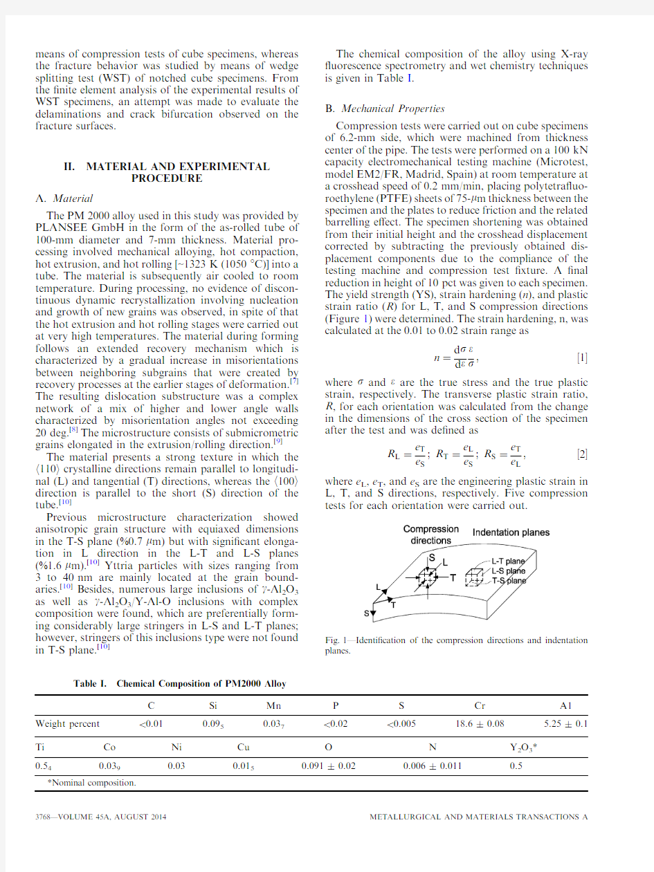
Compression tests were carried out on cube specimens of 6.2-mm side,which were machined from thickness center of the pipe.The tests were performed on a 100kN capacity electromechanical testing machine (Microtest,model EM2/FR,Madrid,Spain)at room temperature at a crosshead speed of 0.2mm/min,placing polytetra?uo-roethylene (PTFE)sheets of 75-l m thickness between the specimen and the plates to reduce friction and the related barrelling e?ect.The specimen shortening was obtained from their initial height and the crosshead displacement corrected by subtracting the previously obtained dis-placement components due to the compliance of the testing machine and compression test ?xture.A ?nal reduction in height of 10pct was given to each specimen.The yield strength (YS),strain hardening (n ),and plastic strain ratio (R )for L,T,and S compression directions (Figure 1)were determined.The strain hardening,n,was calculated at the 0.01to 0.02strain range as
n ?
d r d
e e
r
;?1
where r and e are the true stress and the true plastic strain,respectively.The transverse plastic strain ratio,R ,for each orientation was calculated from the change in the dimensions of the cross section of the specimen after the test and was de?ned as
R L ?e T e S ;R T ?e L e S ;R S ?e T
e L ;?2
where e L ,e T ,and e S are the engineering plastic strain in
L,T,and S directions,respectively.Five compression tests for each orientation were carried out.
Table I.
Chemical Composition of PM2000Alloy
C
Si Mn P S Cr A1Weight percent <0.01
0.095
0.037
<0.02<0.005
18.6±0.08
5.25±0.1
Ti Co Ni Cu O N Y 2O 3*0.54
0.039
0.03
0.015
0.091±0.02
0.006±0.011
0.5
*Nominal
composition.
Fig.1—Identi?cation of the compression directions and indentation planes.
In order to corroborate the results of the compression tests,in particular those regarding to the transverse strain ratio,Vickers hardness measurements were per-formed on L-T,L-S,and T-S cross sections of the pipe (Figure 1)using 196N load for 15seconds.
The WST,often used for characterization of rein-forced concrete and brittle materials [11]and foods [12],was adapted to evaluate the e?ect of the notch orien-tation on the fracture behavior of PM2000alloy.The details of the specimen geometry and loading procedure are sketched in Figure 2.The directional con?guration of the specimens for WST was designated using a two letter code:the ?rst letter designates the normal direc-tion to the notch plane,and the second letter the expected direction of fracture propagation,as de?ned in ASTM standard.[13]The notch orientations of wedge splitting specimens regarding the tube geometry pre-sented in Figure 3were considered in this study.Four WSTs were carried out for each notch orientation.The specimens were compressed to failure at a crosshead speed of 0.5mm/min at room temperature using Mo-likote òG-Rapid-Plus (Dow Corning Europe,Belgium)as a lubricant to reduce the friction between the loading plunger and the support,and the specimen.The fracture of the broken specimens was macroscopically analyzed in low magni?cations with a stereoscopic binocular microscope.
The stress distribution in front of the notch root of notched specimens at the fracture load was evaluated using ?nite element method.In all the notch positions,the coordinate x -axis is normal to the notch plane,whereas y and z axes are parallel to the axis and to the basis of the notch,respectively,Figures 3and 4.
Calculations were made using 8-node isoparametric elements assuming plane strain conditions of the spec-imen.Because the below reported di?erences in YS and n with orientation are small,the material was modelled as an elastoplastic material with an isotropic Von Mises plasticity criterion and isotropic work hardening in which Young’s modulus was 200GPa,and the Poisson’s ratio was 0.3.Small scale yielding was assumed.According to previous work,[14]the ?ow stress curve was de?ned by the expression:
r ?1020t86áe 0:505
p
?3
Figure 4shows the mesh used for the calculations.
Due to symmetry,it was only necessary to model half of the specimen.The nodal load was incrementally ap-plied step by step on the corner nodes of the notch mouth,maintaining a vertical (F v )to splitting (F sp )force ratio of
F v F sp
?2átan
p 6?4
Convergence of results was reached using a mesh
consisting of 1600elements and https://www.doczj.com/doc/4115790380.html,bining experimental results with ?nite element calculations enabled the determination of the critical stress state from the load steps in which specimens had fractured during WST.Because the critical stress state was considered to be determined by both,the magnitude of splitting load and the failure mode,di?erent designa-tions were used.However,it is clear that disregarding of the notch position,the ?nite element model is the same because of the isotropy hypothesis above
stated.
Fig.2—Specimen geometry and loading procedure in wedge splitting
test.
Fig.3—Orientation and designation of specimens of wedge splitting
test.
Fig.4—Finite element model of WST used for calculation of the stress distribution.
III.RESULTS AND DISCUSSION
https://www.doczj.com/doc/4115790380.html,pression Tests
Typical engineering stress–strain plastic strain curves for longitudinal (L),transverse (T),and short transverse (S)are shown in Figure 5.All the curves showed continuous yield behavior.
Transverse plastic strain ratio is similar for tangential and longitudinal test directions of the tube but very di?erent from that in normal direction,Figure 6(a),which reveals that plastic strain in S direction is considerably higher than that in the T direction,when the compression direction is parallel to L direction,and that in the L direction,when the compression is applied in T direction.It can be said that for compression in the plastic regimen in L and T directions,near plane strain conditions prevail on the L-S and T-S planes of the material,respectively.In the case of compression along S direction,the plastic deformation in T direction and L direction is very similar.
Figure 6(b)shows the plot of 0.2pct yield strength YS vs the direction of the compression axis (solid circles).For comparative purposes,the value of the tensile YS in L direction previously obtained [10]is also plotted in Figure 6(b).In addition,in this ?gure,the calculated values of YS according to the Hill’s theory of plastically anisotropic materials [15]were also plotted.These values were calculated using the following expres-sions:
r YS eL T?H 1t1=R L h i à1=2;r YS eT T?H 1t1=R T h i à1=2
;
r YS eS T?H 1=R L t1=R T
h i à1=2
;?5
where R L ,R T ,and R S have been experimentally deter-mined,and H is a constant that is determined applying
the least square method to the di?erences between experimental and calculated yield stresses.[16]
The great discrepancy between Hill’s theory and the current results could be attributed to various causes.First,the Hill’s theory ensures compatibility between grains by assuming homogeneous straining;this causes discontinuity of stress at grain boundaries which is not consistent with requirement for equilibrium.Second,the Hill’s model is rigid plastic,and then the elastic properties of the crystallites are neglected.The elastic anisotropy could also play a signi?cant role in the early stages of plasticity,because grains oriented with a sti?direction parallel to the tensile axis will bear a greater proportion of the applied load.Therefore,the Hill’s theory does not incorporate the full e?ect of texture on the yield strength.Moreover,previous experimental results have also shown that the Hill’s theory
often
Fig.5—Engineering stress-engineering plastic strain curves of com-pression tests in L,T,and S test
directions.
Fig.6—Variation of compression properties with loading orienta-tion:(a )transverse plastic strain ratio,(b )yield strength,(c )strain hardening.
overestimates the e?ect of R value on YS.[17]On the other hand,a considerable amount of experimental work has demonstrated that neither the grain morphol-ogy nor the inclusions morphology signi?cantly in?u-ences on the YS but fracture toughness and ductility.[18–23]
It is worth mentioning the strong similarity between the present results on the variation of YS with test direction,Figure 6(b),and those previously reported for a normalized hot-rolled steel.[20]
The variation of strain hardening exponent,n ,with the orientation of the compression axis is shown in Figure 6(c).The variation of n values with compression direction is small.Moreover,the di?erences cannot be considered statistically signi?cant due to the large scatter of n values that exist in each orientation.B.Hardness Tests
Figure 7(a)shows the e?ect of the indentation plane on the Vickers hardness.It is observed that the hardness is slightly lower on the T-L plane than those on the T-S and L-S planes in which almost identical values were obtained.These di?erences in hardness are consistent with the small variations of YS with test direction.E?ectively,assuming that Hv and YS are approximately related by a factor of 3(Hv %3YS),[24]the values of YS obtained from hardness values of T-S,L-S and T-L planes in Figure 7(a)are 1166,1150,and 1117MPa,respectively.These values follow the same trend as those predicted according to the Hill’s model;however,its
magnitudes are di?erent,particularly,that for S test direction.On the other hand,the experimental results of YS of compression tests are also di?erent from those deduced from hardness tests,particularly,that for L test direction.
It was also noted (Figure 7(b))that the diagonals of the indentation on T-S and L-S planes are di?erent systematically.The diagonals in S direction are always higher than those in T and L directions for T-S and L-S indentation planes,respectively.For indentations on T-L plane,no systematic di?erence in the diagonals was observed.These di?erences in the indentation diagonals are consistent with the above described measurements of transverse plastic strain ratios in compression tests in spite of the complex stress state beneath the indentation.C.Wedge-Splitting Tests
Table II resumes the results of WST for the six notch orientations.In the second column of the table,the average and standard deviation values of the failure splitting load of four tests are given.All specimens frac-tured before the general yield load,P GY =5612kN,which has been previously obtained from the ?nite element analysis as the load at which the full ligament begins to plastically deform.Two failure modes are reported in the last column:one in which fracture propagates along the notch plane,as is the case for LT,TL,ST,and SL notch orientations and that another,for LS and TS orientations,in which fracture propagates along two branches normal to the notch plane,i.e.,parallel to the L-T plane.Moreover,the macroscopic aspect of the fracture of TL,SL,and LS specimens present similar features to those of LT,ST,and TS specimens,respectively.
Figure 8shows the fractographic details of the fracture surface of LT specimen.Figure 8(a)reveals the presence of two groups of delaminations or second-ary fractures,that one of large delaminations regularly spaced through the specimen thickness and that one of small delaminations heterogeneously distributed be-tween the large delaminations.The delaminations are parallel to L-T plane.Figures 8(a)and (b)show that the fracture between delaminations,i.e.,the main fracture,has occurred by a ductile mechanism,whereas Figures 8(b)and (c)reveal that the delaminations have occurred by a brittle mechanism.Electron backscatter-ing di?raction (EBSD)grain orientation image in Figure 8(d)reveals that the delamination follows a mainly intergranular path.
Figure 9shows the fractographic details of the fracture surface of ST and TS specimen.The fracture of ST specimen,occurring along the notch plane (Figures 9(a)and (b)),presents an identical aspect,Figure 9(c),to that showed at the surface of delamina-tion,Figure 8(c),for LT specimen.The fracture of TS specimen (Figures 9(d)and (e))initiates at one point or at two points,one on each side of the symmetry axis of the notch,and then propagates catastrophically along one or two branches orthogonal to the notch plane,i.e.,parallel to L-T plane.The fractographic features of the fracture surface of TS specimen (Figure 9(f))are
similar
Fig.7—E?ect of the indentation plane on:(a )HV20hardness num-ber,(b )diagonal length of HV20impressions;d L ,d T ,and d S are the diagonal length in L,T,and S directions,respectively.
Table II.Experimental Results and Finite Element Analysis Results of Wedge-Splitting Tests
Specimen
Splitting
Load (kN)
Critical Stress Ratio
(
σ
ij
/
σ
ys
)
Failure Mode
xx
yy
zz
xy
Lateral View
Fracture Surface
LS 4.73±0.14 2.736* 1.2610.827
TS 4.25±0.20 2.307* 1.2080.69
LT 4.43±0.15 2.337 1.552
TL 4.12±0.06 2.277 1.435
SL 3.61±0.37 2.089
ST 3.71±0.42 2.154
*The critical value of this stress component for crack propagation at S direction should be higher than that in which crack branching actually occurred.
to those of the delaminations of LT specimen in Figure 8(c)and of the fracture surface of ST specimen in Figure 9(c).From this fractographic analysis,it is evident that the planes parallel to L-T plane are planes of weakness.
It is well known that there are two factors enhancing the formation of delaminations in steels:the preferred orientation of the grains and their morphology and arrangement in the mesoscopic scale.[21,25–27]However,it has been shown that the morphology and arrangement of grains rather than texture are the more important factor controlling the delamination formation.[21]Both factors are considered below to explain the cause of the delaminations and crack branching in PM2000alloy.The above transverse plastic strain ratio measure-ments in compression tests have shown that when a sample is plastically deformed in L or T direction (h 110i crystallographic direction),the cross section of the samples presents a strong tendency to deform in plane strain conditions in the L-S or T-S planes,respectively,rather than axially symmetric ?ow.Previous Bishop-Hill type crystallographic analysis has demonstrated that for [110]?ber-textured BCC materials,the necessary stress to produce axially symmetric ?ow is 3/2of that required for plane strain ?ow.[28]Consequently,the material presents a strong tendency to deform by plane-strain ?ow.Moreover,using the same analysis type,it was also demonstrated that intergranular transverse tensile stres-ses act perpendicular to the {001}planes parallel to the applied stress.[29]Di?raction studies have corroborated that the transverse stresses acting on longitudinally aligned planes are tensile on (100)planes and compres-sive on (110)planes,being their absolute magnitude of the order of 1/5and 1/3of the material ?ow stress.[30,31]Having into account that the L-T plane is a (100)plane and that the h 110i crystallographic direction is the main direction in L and T directions,it could be thus expected that the material texture enhances the propensity to delamination for LT and TL specimens or to branching for LS and TS specimens.
In order to evaluate the last assertion,it is necessary to perform additional experimental work aimed to separate the e?ect of microstructural morphology from texture.[32]Following the reviewer’s suggestions,[32]WS specimens were machined with the notch plane parallel to other two (110)planes that are equivalent crystallo-graphically but not morphologically.In accord with the reviewer,this involves two 45degree rotations prior to machining the notch,Figure 10.It could be anticipated that if the specimen delaminates or fractures along the crystallographically equivalents (001)planes,which is not the L-T plane,the texture would be the main cause of the delamination or branching.If the specimen delaminates along the of L-T plane,the microstructure morphology would be the main cause of the delamin-ations.WS specimens with three notch
positions
Fig.8—Fractographic details of fracture surface of LT specimen:(a )SEM image showing the general aspect of delaminations.(b )SEM image showing the delaminations (D)and the ductile character of the main fracture (DF).(c )SEM image at higher magni?cations of the delamination surface.(d )EBSD grain orientation image of A–A section of (a)showing the preferably intergranular path of the delaminations.
designated according to Figure 10as XY,XZ,and YX were machined and then tested in the same conditions as the other WS specimens.It is expected that the crystallographic orientations of the notch of XY,XZ,and YX in Figure 10are equivalent to those of LT,TS,and TL in Figure 3,respectively.
Microtexture analysis was carried out by the EBSD technique in X-Z plane (see Figure 10)in order to be compared with that previously obtained for the L-S
plane (see Figure 1).[10]The results were represented by means of an inverse pole ?gure (IPF)maps which give the orientation of a macroscopic direction with respect to a speci?c crystal direction.Figures 11(a)and (b)illustrate the IPF maps for L-S and X-Z planes,indicating the h uvw i directions parallel to the L,T,and S and X,Y,and Z directions,respectively.Figure 11(a)reveals that more than 80pct of the indexed grains presents the h 110i parallel to L
direction;
Fig.9—Fractographic details of fracture surface of ST and TS specimens:(a )Optical macrograph showing the lateral view of fracture of ST specimen.(b )Optical macrograph showing the general appearance of the fracture surface of ST specimen.(c )SEM image at higher magni?ca-tions of the fracture surface of ST specimen.(d )Optical macrograph showing the lateral view of fracture of TS specimen.(e )Optical macro-graph showing the general appearance and the initiation zones (IZ)of the fracture in the bottom fragment in (d).(f )SEM image at higher magni?cations of the fracture surface of TS specimen.
however,in T direction the crystalline direction of one half of indexed grain is parallel to h 110i direction whereas that of the other one half is oriented parallel to h 111i direction.In S direction about 70pct of the indexed grains,the crystalline direction is parallel to h 100i direction and that of the remainder grains is parallel to h 111i direction.Figure 11(b)reveals the pre-sence of the same orientations than those in Figure 11(a)but results much less https://www.doczj.com/doc/4115790380.html,paring Figures 11(a)and (b)results,it is evident that the morphology of the grains in the L-S plane is more elongated that in the X-Z plane.
Figure 12shows the fractographic details of XY specimen.Fracture initiates in various points of the notch tip and then propagates along a plane tilted %30deg regarding to the notch plane,Figure 12(a).Figure 12(b)shows that the longitudinal axis of the fracture facets is inclined %45deg to the macroscopic direction of the fracture propagation.The microscopic features of the fracture surface in Figure 12(b)are
similar to those showed in Figures 8(c)and 9(f)for the surfaces of delamination and crack branching of LT and TS specimens.The material microstructure below the fracture pro?les along AA and BB sections (see Figure 12(a))presents an elongated morphology,Figures 12(c)and (d).These results suggest that the fracture has occurred along the L-T plane.
Figure 13shows the fractographic details of XZ specimen.The fracture initiation point is located at the notch tip,and then the fracture propagates following a stepped path through the specimen ligament,Figure 13(a).The stepped path consists in brittle cracks separated by ductile walls,Figures 13(b)and (c).The longitudinal axis of the facets of brittle cracks is inclined %45deg regarding to the macroscopic propagation direction of the main fracture.Moreover,the fracto-graphic features of the surface of brittle cracks,Figure 13(b),are similar to those shown in Figures 8(c)and 9(f).The fracture pro?le parallel to the notch basis (AA section in Figure 13(a))reveals that the brittle cracks are tilted %30deg regarding to the notch plane whereas the ductile walls are inclined %90deg,Figure 13(c).Furthermore,the brittle cracks have attempted to progress into the material in spite of the presence of ductile tears,Figure 13(c).In higher mag-ni?cation,it is observed in Figure 13(d)that fracture in brittle cracks run parallel to the longitudinal axis of the grains following an intergranular path,inset of Figure 13(d).The fracture pro?le along the specimen ligament (BB section in Figure 13(a))is more smooth than the pro?le along the AA section.Moreover,the grains below the fracture pro?le present an equiaxial morphology,Figure 13(e).These results also suggest that the fracture has occurred along the L-T plane.The above results con?rm that L-T plane is a microstructurally weak plane;however,such results do not allow an assessment of the e?ects of microstruc-ture morphology either texture or of the
internal
Fig.10—Drawing showing the orientation and designation of wedge splitting specimens with notch orientation modi?ed.Note that the crystallographic orientations of the notch of XY,XZ,and YX speci-mens are equivalent to those in Fig.3of LT,TS,and TL specimens,
respectively.
Fig.11—Inverse pole ?gure (IPF)maps in:(a )L-S plane (see Fig.1),(b )X-Z plane (see Fig.10).
texture-induced stresses on the delaminations or crack branching.Firstly,because of the microstructural mor-phology is distinctively di?erent.In L-S plane,it is markedly elongated,Figure 11(a),whereas in the X-Z plane,it is nearly equiaxial,Figure 11(b).On the other hand,the texture in L-S plane is also signi?cantly di?erent from that of X-Z plane,since the texture intensity in the latter plane is much less than that of the former.
Subsequently,we consider what stress state can enhance the delamination or the branching of the material.Figure 14shows typical contours around the notch tip of r xx ,r yy ,r zz ,and r xy stress components.The stress distributions along X direction for LT specimens and along Y direction for TS specimens are shown in Figures 15(a)and (b),respectively.In this regard,and as outlined above,the ?nite element model is always the same,regardless of the notch position because of the isotropy assumption.The reason to di?erentiate be-tween LT and TS specimens lies in which the macro-scopic fracture mechanism is di?erent and then controlled by di?erent stress components.In the third column of Table II ,the maximum values of the stress
components at the fracture instant relevant to the failure mode are given.In order to explain the fracture propagation along the notch plane for LT,TL,ST,and SL notch orientations,it is considered that the stress distribution of r xx stress component (Figures 14(a)and 15(a))would be the most appropriate component to explain the obtained results.
The fracture propagation along two branches normal to the notch plane for LS and TS notch orientations could be explained by the distribution of r yy stress component ahead of the notch tip,Figures 14(a)and 15(a)but could also be justi?ed by the combination of both the r xy stress and r yy stress components to both sides from the notch tip Figures 14(b)and 15(b).In this regard,it must be noted that the r xy stress component is maximum on both sides of the notch tip and with equal magnitude than r yy stress component,Figure 14(b).This is consistent with the presence (Figure 9(e))of two fracture initiation points,one on each side of the notch tip,in TS specimens.
Cook and Gordon analyzed theoretically the problem of the crack branching in a hypothetic material with
a
Fig.12—Fractographic details of the fracture of XY specimen (see Fig.10).(a )SEM image showing the macroscopic aspect of the fracture sur-face.The optical macrograph in the inset shows the fracture pro?le.(b )SEM image showing the microscopic features of the fracture surface.The white arrow indicates the fracture propagation direction.Further details of the fracture surface in higher magni?cations are shown in the in-set.(c )SEM image of the fracture pro?le of BB cross section indicated in (a).Further details of the fracture surface in higher magni?cations are shown in the inset.(d )SEM image of the fracture pro?le of AA cross section indicated in (a).Further details of the fracture surface in higher magni?cations are shown in the inset.
bond plane normal to the crack in which the adhesion was not perfect.[29]They consider three possibilities:1.Very weak bond plane.The fracture begins ahead of the notch tip at the intersection of the bond plane with the notch plane where the r yy stress
component is a maximum (Figures 9(a)and 10(a)).Subsequently,and in agreement with Cook and Gordon,the branch propagates,until the value of the stress intensity factor is lower than the critical value for crack propagation.Finally,the
material
Fig.13—Fractographic details of the fracture of XZ specimen (see Fig.10).(a )SEM image showing the macroscopic aspect of the fracture sur-face.The optical macrograph in the inset shows the fracture pro?le.(b )SEM image showing the microscopic details of the fracture surface with further details of a brittle crack at higher magni?cations into the inset.The white arrow indicates the fracture propagation direction.BC,brittle crack.DT,ductile tear (c )Optical image of AA cross section indicated in (a),showing the details of the fracture pro?le along the Y direction.(d )SEM image showing the details of one of various crack tips at (c)and further details at the inset revealing the intergranular character of the fracture pro?le.(e )SEM image showing the details of the fracture pro?le at the BB cross section indicated in (a).
will deform,but without the notch effect,until the fracture reinitiates again.
2.Mid-strong bond plane.If the bond plane has sur-vived the maximum value of the r yy stress component ahead of the notch tip,the fracture could be con-trolled by the r xy stress component.The maximum values of r xy stress component are symmetrically lo-cated off the notch axis on the notch surface and are numerically similar to that of r yy stress component at the same location,Figures 9(b)and 10(b).Cook and Gordon considered that this possibility rather improbable and only plausible in case the fracture is propagation controlled.However,and as it is the case for LS and TS notch orientations,the fracture can be initiation-controlled at the notch tip,in which case the event is probable to occur.Therefore,for LS and TS notch orientations,the fracture can be deter-mined by r yy and r xy stress components.In this case,the fracture initiates and catastrophically propagates at one half or both halves of the specimen beside the notch tip,Figure 11.
3.Strong bond plane.If the bond plane does not fail,then the main crack will cross it,and the fracture would extend as in a homogeneous medium.It is noteworthy that using the ?rst two methods a notable improvement of the fracture toughness (upper shelf)can be obtained.[10,33–35]
On the other hand,the r zz -stress component induced by the constraint at the crack tip (Figures 14(a)and 15(a))has been considered as the driving stress for delamination.[20,21,25–27,36–39]Apparently,the results at the last four rows of Table II do not support this explanation,because the r zz /r ys values at fracture of LT and TL specimens,1.552and 1.435,respectively,are considerably lower than the r xx /r ys values of SL and ST
specimens, 2.08and 2.154,respectively.However,it must be taken into account that the texture-induced stress intensi?cation for LT and TL specimens has been neglected in the ?nite element analysis.It is also possible,like in the case of the crack branching that the delamination initiates when a critical shear stress is reached and then extends by the action of r zz -stress component.Therefore,it can be concluded that delam-ination could e?ectively be a r zz -controlled event,although a contribution from the shear stress to the fracture initiation can still not be discarded.
Previous work of the authors has shown that delam-ination of an extruded bar of PM2000alloy without texture was a strain rate-controlled process and that the cause of delamination could be attributed to the hydrogen stored in the material during its particular processing.[40]Moreover,the fracture morphology of the delaminations was very similar to that observed (Fig-ure 8(c)),for the material used in the present study.In order to verify this possibility,additional WST with LT and SL notch orientations and tensile tests of longitu-dinal specimens were performed at 5910à5and 5910à2s à1strain rates.The results indicated that delamination and ductility loss are not a strain rate-controlled process.These results are consistent with the lower level of hydrogen content of 1.7ppm of the material used in the present study in comparison with that of 11ppm of previous work.[40]
Taking into account the reported causes for delam-ination [20,21,25–27,36–39,41]and the present results,it is proposed that the microstructural causes of the delam-inations and crack branching for PM2000alloy are the alignment in the mesoscopic scale of the ultra?ne grain structure which is enhanced by both the texture-induced internal stresses and the presence in the grain
boundaries
Fig.14—Contours of the stress components:(a )TL specimen (P sp =4.12kN),(b )TS specimen (P sp =4.25kN).The numbers on the plots indicate the stress level.
of yttria dispersoids and impurity contamination.On the other hand,although the driving stress for the delamination and crack branching is the normal stress to the delaminations and branches,respectively,the e?ect of the shear stress cannot still discarded.
For the evaluation of the anisotropy of the material toughness,the splitting loads in Table II were ranked in descending order according to both the failure mode and the fracture micromechanism,as follows:
–Crack propagation along the notch plane—ductile fracture with delaminations:P sp (LT)>P sp (TL).
–Crack propagation along the notch plane—inter-granular brittle fracture:P sp (ST)>P sp (SL).
–Crack propagation normal to the notch plane—inter-granular brittle fracture:P sp (LS)>P sp (TS).The higher splitting load for LT (ST)notch orientation in comparison with TL (SL)notch orientation could be explained by the combination of two e?ects,the lower e?ective grain projected length and the slight lower yield
strength.The signi?cant di?erence in splitting load between LT(TL)-and ST(SL)-notched specimens is due to the di?erences in the fracture mechanism.From the results of splitting load and failure mode of LS-and TS-notched specimens,it is also clear that the splitting load for fracture propagation along the notch should be higher than that for actual crack branching of 4.73and 4.25kN,respectively.Therefore,in case the fracture occurred along the notch plane and not via branching as actually occurred,the fracture toughness would be higher for LS-and TS-notched specimens.
IV.CONCLUSIONS
The anisotropy in the mechanical behavior of a FeCrAl ODS ferritic alloy supplied as a tube of 100mm in diameter and 7mm in thickness was investigated using cubic and wedge splitting specimens.The follow-ing results were obtained:
1.The YS values obtained from compression speci-mens taken in longitudinal and short directions are very similar from each other and on average ~80MPa lower than the specimen taken in tangen-tial direction.
2.The values of transverse strain ratio obtained from compression specimens taken in tangential and lon-gitudinal directions indicated a strong tendency of the material to deform in plane strain conditions on T-S and L-S,respectively,while that of compression specimen in short direction presented a nearly iso-tropic behavior.
3.The microstructural causes of the delaminations and crack branching are the alignment in the meso-scopic scale of the ultra?ne grain structure which is enhanced by both the texture-induced internal stres-ses and the presence in the grain boundaries of yt-tria dispersoids and impurity contamination.
4.The driving stress for the delamination and crack branching is the normal stress to the delaminations and branches,respectively;however,the e?ect of the shear stress component cannot still discarded.
5.In the case that the fracture occurred along the notch plane,the fracture toughness would be higher for LS-and TS-notched specimens.
ACKNOWLEDGMENTS
Financial support of the Spanish Ministerio de Edu-cacio
n y Ciencia through a Coordinated Project in the Energy Area of Plan Nacional 2006(ENE2006-15170-C02)is gratefully acknowledged.The authors are grateful to the Editor,Key-Reader and Reviewers efforts and constructive comments that have signi?-cantly improved the original manuscript.
REFERENCES
1.A.Kimura,R.Kasada,N.Iwata,H.Kishimoto,J.Isselin,C.H.Zhang,P.Dou,and J.H.Lee:Proc.of the 2009
International
Fig.15—Stress distribution below the notch tip along:(a )Y direc-tion for TL specimen (P sp =4.12kN),(b )X direction for TS speci-men (P sp =4.25kN).
Congress Advances in Nuclear Power Plants,Tokyo,Japan,2009, pp.9220–25.
2.G.H.Gessinger and O.Mercier:Powder Metall.Int.,1978,vol.10,
p.203.
https://www.doczj.com/doc/4115790380.html,ai,M.Harada,H.Okada,M.Inoue,S.Nomura,S.
Shikakura,T.Nishida,M.Fujiwara,and K.Asabe:J.Nucl.
Mater.,1993,vol.204,pp.74–80.
4.M.J.Alinger,G.R.Odette,and G.E.Lucas:J.Nucl.Mater.,2002,
vols.307–311,pp.484–89.
5.R.Kasada,S.G.Lee,J.Isselin,J.H.Lee,T.Omura,A.Kimura,T.
Okuda,M.Inoue,https://www.doczj.com/doc/4115790380.html,ai,S.Ohnuki,T.Fujisawa,and F.Abe:J.
Nucl.Mater.,2011,vol.417,pp.180–84.
6.M.S.Joo:Ph.D.Thesis,Pohang University of Science and Tech-
nology,Korea,2012,pp.38–58.
7.P.Cizek and B.P.Wynne:Mater.Sci.Eng.A,1997,vol.230,
pp.88–94.
8.D.N.Lee:Scripta Metall.Mater.,1995,vol.32,pp.1689–94.
9.C.Capdevila,https://www.doczj.com/doc/4115790380.html,ler,H.Jelenak,and H.Bhadeshia:Mater.
Sci.Eng.A,2001,vol.316,pp.161–65.
10.J.Chao, C.Capdevila,M.Serrano, A.Garc?a-Junceda,J.A.
Jime nez,G.Pimentel,and E.Urones-Garrote:Metall.Mater.
Trans.A,2013,vol.44A,pp.4581–94.
11.E.Bru hwiler and F.H.Wittmann:Eng.Fract.Mech.,1990,vol.35
(1/2/3),pp.117–25.
12.J.F.V.Vincent,G.Jeronimidis,A.A.Kahn,and H.Luyten:J.
Text.Stud.,1991,vol.22,pp.45–57.
13.ASTM-E-399-09:Annual Book of ASTM Standards,vol.03.01,
ASTM International,West Conshohocken,PA,2011,pp.502–34.
14.I.Toda-Caraballo,J.Chao,L.E.Lindgren,and C.Capdevila:
Script Mater.,2010,vol.62(1),pp.41–44.
15.R.Hill:The Mathematical Theory of Plasticity,Chap12,Oxford
University Press,London,1950,pp.317–21.
16.G.Baldi and G.Buzzichelli:Met.Sci.,1978,vol.12,
pp.459–72.
17.W.F.Hosford:Mechanical Behavior of Materials,Chap6,Cam-
bridge University Press,New York,2005,pp.80–98.
18.I.Kozasu and H.Kubota:Trans.ISIJ,1971,vol.11,pp.321–30.
19.W.Dahl:Steel:A Handbook for Materials Research and Engi-
neering,Fundamentals,Springer Verlag,Berlin,1972,vol.1,pp.
247–48.
20.W.B.Morrison:Met.Technol.,1975,vol.2,pp.33–41.21.B.Mintz,W.B.Morrison,P.I.Welch,and G.J.Davies:in Texture
of Materials,vol.2,G.Gottstein,and K.Lu cke,ed.,Springer Verlag,Berlin,1978,pp.465–74.
22.W.A.Spitzig and R.J.Sober:Metall.Trans.,1981,vol.12A,
pp.281–91.
23.S.K.Paul and S.Mishra:Met.Mater.Process.,1992,vol.4(3),
pp.189–202.
24.W.F.Hosford:Mechanical Behavior of Materials,Chap.5,Cam-
bridge University Press,New York,2005,p.64.
25.W.B.Morrison,B.Mintz,and C.Cochrane:in Preprint of the Paper
Presented at the Conf.on‘‘Controlled Processing of HSLA Steels’’, York University,Paper No.1,British Steel Corporation,1976. 26.D.S.Dablowski,P.J.Konkol,and M.F.Baldy:Met.Eng.Quart.,
1976,vol.16,pp.22–32.
27.B.Mintz:Met.Technol.,1980,vol.7,pp.127–29.
28.W.F.Hosford:Trans.TMS AIME,1960,vol.230,pp.12–15.
29.J.Gil-Sevillano:Scripta Metall.,1986,vol.20,pp.1111–14.
30.J.Gil-Sevillano,J.Alkorta,D.Gonza lez,S.Van Petegem,and U.
Stuhr:Adv.Eng.Mater.,2008,vol.10(10),pp.951–54.
31.J.Gil-Sevillano,D.Gonza lez,and J.Mart?nez-Esnaola:Mater.
Sci.Forum,2007,vol.550,pp.75–84.
32.Private communication with referee’s comments from Editorial
Sta?of MMTA(T.M.Pollock,Editor),2013.
33.A.J.McEvily,Jr and R.H.Bush:Trans.ASM,1962,vol.55,
pp.655–66.
34.Y.Kimura,T.Inoue,F.Yin,and K.Tsuzaki:Science,2008,
vol.320,pp.1057–60.
35.M.Jafari,Y.Kimura,and K.Tsuzaki:Metall.Mater.Trans.A,
2012,vol.43A,pp.2453–65.
36.B.L.Bram?tt and A.R.Marder:in Processing and Properties of
Low-carbon Steel,J.M.Gray,ed.,Metallurgical Society of AIME, New York,1972,pp.191–224.
37.J.D.G.Groom and J.F.Knott:Met.Sci.,1975,vol.9,pp.390–400.
38.P.Brozzo and G.Buzzichelli:Scripta Mater.,1976,vol.10,
pp.235–40.
39.R.Song,D.Ponge,and D.Raabe:Acta Mater.,2005,vol.53,
pp.4881–92.
40.J.Chao, C.Capdevila-Montes,and J.L.Gonza lez-Carrasco:
Mater.Sci.Eng.A,2009,vol.515(1–2),pp.190–98.
41.J.Cook and J.E.Gordon:Proc.R.Soc.A,1964,vol.282A,
pp.508–20.