SAE Technical Standards Board Rules provide that: “This report is published by SAE to advance the state of technical and engineering sciences. The use of this report is entirely voluntary, and its applicability and suitability for any particular use, including any patent infringement arising therefrom, is the sole responsibility of the user.”
SAE reviews each technical report at least every five years at which time it may be reaffirmed, revised, or cancelled. SAE invites your written comments and suggestions.
QUESTIONS REGARDING THIS DOCUMENT: (724) 772-8512 FAX: (724) 776-0243
TO PLACE A DOCUMENT ORDER; (724) 776-4970 FAX: (724) 776-0790
SAE WEB ADDRESS https://www.doczj.com/doc/4d13547508.html,
1.Scope—This SAE Recommended Practice defines the information contained in the header and data fields of
non-diagnostic messages for automotive serial communications based on SAE J1850 Class B networks. This document describes and specifies the header fields, data fields, field sizes, scaling, representations, and data positions used within messages.
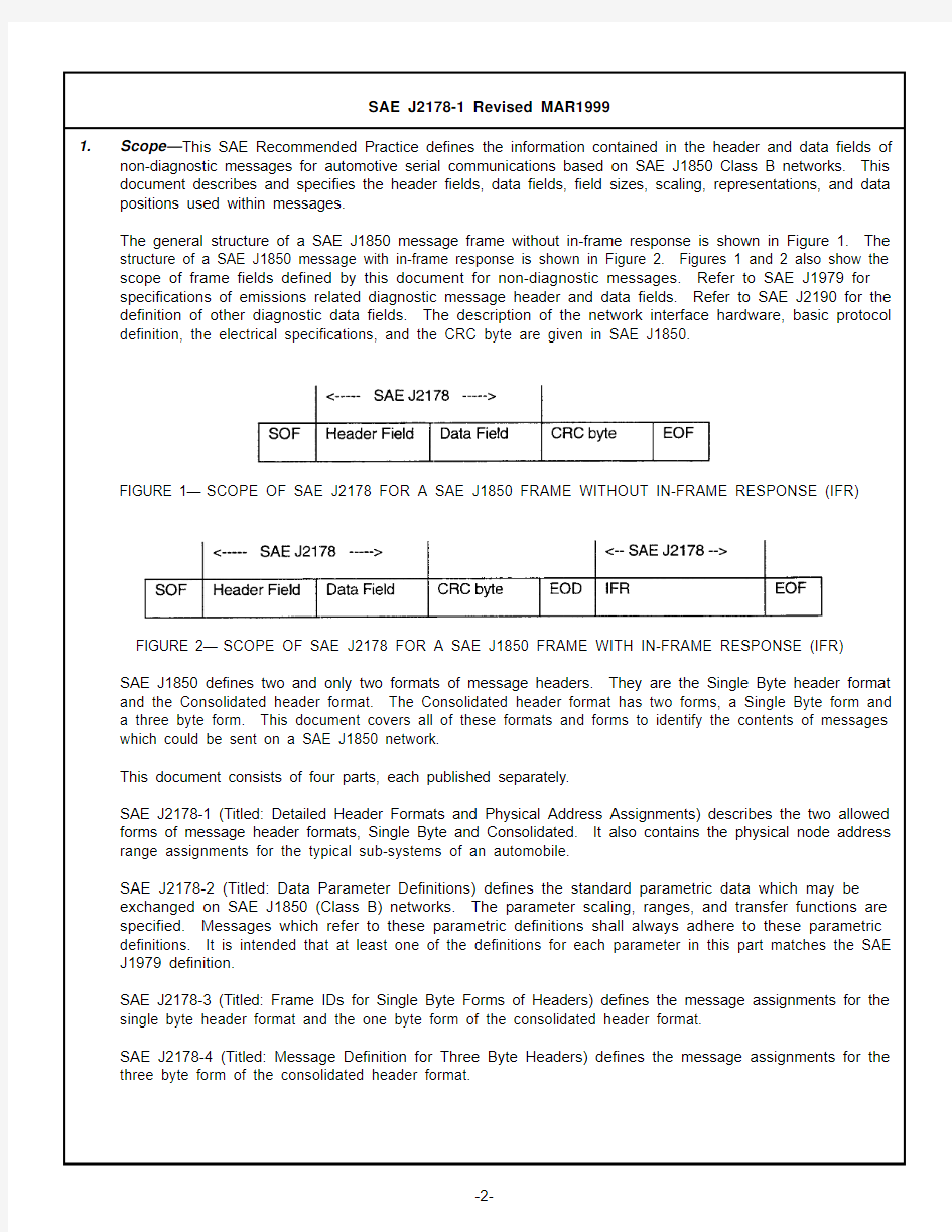
The general structure of a SAE J1850 message frame without in-frame response is shown in Figure 1. The structure of a SAE J1850 message with in-frame response is shown in Figure 2. Figures 1 and 2 also show the scope of frame fields defined by this document for non-diagnostic messages. Refer to SAE J1979 for specifications of emissions related diagnostic message header and data fields. Refer to SAE J2190 for the definition of other diagnostic data fields. The description of the network interface hardware, basic protocol definition, the electrical specifications, and the CRC byte are given in SAE J1850.
FIGURE 1—SCOPE OF SAE J2178 FOR A SAE J1850 FRAME WITHOUT IN-FRAME RESPONSE (IFR)
FIGURE 2—SCOPE OF SAE J2178 FOR A SAE J1850 FRAME WITH IN-FRAME RESPONSE (IFR)
SAE J1850 defines two and only two formats of message headers. They are the Single Byte header format and the Consolidated header format. The Consolidated header format has two forms, a Single Byte form and
a three byte form. This document covers all of these formats and forms to identify the contents of messages
which could be sent on a SAE J1850 network.
This document consists of four parts, each published separately.
SAE J2178-1 (Titled: Detailed Header Formats and Physical Address Assignments) describes the two allowed forms of message header formats, Single Byte and Consolidated. It also contains the physical node address range assignments for the typical sub-systems of an automobile.
SAE J2178-2 (Titled: Data Parameter Definitions) defines the standard parametric data which may be exchanged on SAE J1850 (Class B) networks. The parameter scaling, ranges, and transfer functions are specified. Messages which refer to these parametric definitions shall always adhere to these parametric definitions. It is intended that at least one of the definitions for each parameter in this part matches the SAE J1979 definition.
SAE J2178-3 (Titled: Frame IDs for Single Byte Forms of Headers) defines the message assignments for the single byte header format and the one byte form of the consolidated header format.
SAE J2178-4 (Titled: Message Definition for Three Byte Headers) defines the message assignments for the three byte form of the consolidated header format.
2.References
2.1Applicable Publications—The following publications form a part of this specification to the extent specified
herein. Unless otherwise specified, the latest issue of SAE publications shall apply.
2.1.1SAE P UBLICATIONS—Available from SAE, 400 Commonwealth Drive, Warrendale, PA 15096-0001.
SAE J1213-1—Glossary of Vehicle Networks for Multiplex and Data Communication
SAE J1850—Class B Data Communication Networks Interface
SAE J1930—Electrical/Electronic Systems Diagnostic Terms, Definitions, Abbreviations, and Acronyms
SAE J1979—E/E Diagnostic Test Modes
SAE J2190—Enhanced E/E Diagnostic Test Modes
2.1.2ANSI/IEEE P UBLICATION—Available from ANSI, 11 West 42nd Street, New York, NY 10036-8002.
ANSI/IEEE 754-1985—IEEE Standard for Binary Floating-Point Arithmetic
3.Definitions
3.1Data [Data Field]—Data and data field are used interchangeably in this document and they both refer to a
field within a frame that may include bytes with parameters pertaining to the message and/or secondary ID and/or extended addresses and/or test modes which further defines a particular message content being exchanged over the network.
3.2Extended Address—The extended address is a means to allow a message to be addressed to a
geographical location (such as geographic) or zone of the vehicle, independent of any node's physical address.
3.3Frame—A frame is one complete transmission of information which may or may not include an In-Frame
Response. The frame is enclosed by the start of frame and end of frame symbols. For Class B networks, each frame contains one and only one message (see "message" definition below).
3.4Frame ID—The Frame ID is the header byte for the Single Byte Header format and the one byte form of the
consolidated header format. The definition of the frame ID is found in SAE J2178-3. This header byte defines the target and source and content of the frame.
3.5Functional Addressing—Functional addressing allows a message to be addressed or sent to one or more
nodes on the network interested in that function. Functional addressing is intended for messages that may be of interest to more than a single node. For example, an exterior lamp "off" message could be sent to all nodes controlling the vehicle exterior lamps by using a functional address. The functional address consists of a primary ID and may include a secondary ID and may also include an extended address.
3.6Header [Header Field]—The header (or header field, used interchangeably) is a one or three byte field within
a frame which contains information about the message priority, message source and target addressing,
message type, and in-frame response type.
3.7In-Frame Response (IFR) Type—The IFR type identifies the form of the in-frame response which is expected
within that message.
3.8Load—The load command indicates the operation of directly replacing the current/existing value of a
parameter with the parameter value(s) contained in the message.
3.9Message—A message consists of all of the bytes of a frame excluding the delimiter symbols (SOF, EOD,
EOF, NB).
3.10Modify—The modify command indicates the operation of using the message data parameter value to change
(e.g., increment, decrement, or toggle) the current/existing value.
3.11Parameter—A parameter is the variable quantity included in some messages. The parameter value, scaling,
offset, units, transfer function, etc., are unique to each particular message. (The assigned parameters are contained herein.)
3.12Physical Addressing—Physical addressing allows a message to be addressed to a specific node or to all
nodes or to a non-existent, null node. The information in this message is of relevance only to a particular node, so the other nodes on the bus should ignore the message, except for the case of the "all nodes" address.
3.13Primary ID—The primary ID identifies the target for this functional message. This is the primary discriminator
used to group functions into main categories.
3.14Priority—The priority describes the rank order and precedence of a message. Based upon the SAE J1850,
Class B arbitration process, the message with the highest priority will win arbitration.
3.15Report—A report indicates the transmission of parametric data values, based on: a change of state; a change
of value; on a periodic rate basis; or as a response to a specific request.
3.16Request—A request is a command to, or a query for data, or action from another node on the network.
3.17Response Data—The response data is the information from a node on the network in response to a request
from another node on the network. This may be an in-frame response or a report type of message.
3.18Secondary ID—The secondary ID (along with the primary ID or Frame ID) identifies the functional target node
for a message. The purpose of the secondary ID field within the frame is to further define the function or action being identified by the primary ID.
4.Abbreviations and Acronyms
A/C - Air Conditioning
ASC - ASCII Encoded SLOT
BCD - Binary Coded Decimal (BCD) SLOT
BMM - Bit Mapped with Mask SLOT
BMP - Bit Mapped without Mask SLOT
CRC - Cyclic Redundancy Check
CS - Checksum
DTC - Diagnostic Trouble Code
EOD - End of Data
EOF - End of Frame
ERR - Error Detection
EV-ETS - Electric Vehicle Energy Transfer System
EVSE - Electric Vehicle Supply Equipment
HVAC - Heating, Ventilation, Air Conditioning
ID - Identifier
IFR - In-Frame Response
LSB - Least Significant Bit/Byte
MSB - Most Significant Bit/Byte
NB - Normalization Bit
PID - Parameter IDentification (number, NOT the primary ID, (See Section 7)
PKT - Multiple Parameter Packet SLOT
PRN - Parameter Reference Number
SED - State Encoded SLOT
SFP - Signed Floating Point (Scientific Notation) SLOT
SLOT - Scaling, Limit, Offset, and Transfer Function (See Section 8)
SNM - 2's Complement Signed Numeric SLOT
SOF - Start of Frame
UNM - Unsigned Numeric SLOT
VIN - Vehicle Identification Number
5.General Information
5.1Part 1 Overview—The messages defined by this four part document are specified for networks using single
byte headers or consolidated one and three byte headers as specified in SAE J1850. Sections 6 and 7 of SAE J2178-1 provide the system architecture for the different possible headers used in Class B network communication (see Appendix A for supporting discussion). Section 8 of SAE J2178-1 defines the data fields used by the different header byte formats. Section 9 of SAE J2178-1 defines the physical address assignments.
Figure 3 shows an overview of this part (Part 1) which encompasses the different possible messages and their component parts.
FIGURE 3—PART 1 OVERVIEW
SAE J1850 defines two and only two formats of message headers. They are the Single Byte header format and the Consolidated header format. The Consolidated header format has two forms, identified by the value of the H Bit. The two forms are: a one byte form and a three byte form. The information in the header field for both formats contains target, source, priority and message type information, while the data field contains additional addressing and/or parametric information and/or diagnostic test modes. This information is explicitly defined in some headers and implicitly defined in others. Messages defined by this document (Parts 1, 2, 3, and 4) are classified generally into two types:
a.Requests, that is, commands (load or modify) or queries for data, and
b.Responses, that is, reports or acknowledgments.
When a node generates a request, the target nodes which are responsible for the requested data or function must respond by reporting the requested information or by performing the requested function. For responses (that is, reports or acknowledgments), data information that a node responds with may have been previously requested by another node, or reported by the node when the desired information has changed, or reported by the node on a periodic basis.
SAE J2178-1 describes the overall structure of messages. In total, parts 1, 2, 3, and 4:
a.Fully define SAE (automotive industry) standard messages.
b.Reserve messages for future SAE standardization.
c.Reserve messages for manufacturers to allocate, which are typically unique or proprietary to that
manufacturer.
In order to comply with this document, implementations need to use the defined messages on SAE J1850 networks in the exact way that they are defined here. However, there are a large number of message codes that are reserved for each manufacturer to independently allocate.
5.2In-Frame Response Field Formats—The total number of bytes in the frame (not including frame delimiters) is
12, including the header (1 or 3 depending on header type), data (both in the message and IFR), and single byte CRC. Therefore, the total number of message and IFR data bytes can be 10 if using a single byte header or the one byte form of the consolidated header, or 8 bytes if using the three byte form of the consolidated header.
5.2.1I N-F RAME R ESPONSE T YPE 0—The in-frame response type 0 is used to indicate the form without any in-frame
response.
5.2.2I N-F RAME R ESPONSE T YPE 1—The in-frame response type 1 is a single byte response from a single
responder. The response byte shall be the physical address of a receiver of the message. No CRC byte is included for this response data.
5.2.3I N-F RAME R ESPONSE T YPE 2—The in-frame response type 2 is a single byte response from multiple
responders. The response byte(s) shall be the physical address of the receiver(s) of the message. No CRC byte is included for the response data.
5.2.4I N-F RAME R ESPONSE T YPE 3—The in-frame response type 3 is a multiple byte response from a single
responder. The response bytes shall be data (generally not its address) from a single responder. The second CRC byte is included for the data integrity of the response data. The actual in-frame response data shall be one byte in length, as a minimum.
Figure 4 illustrates the four IFR types.
FIGURE 4—TYPES OF IN-FRAME RESPONSE
6.Single Byte Header Messages and Format—For single byte header messages, the entire byte is used to
define the message identifier (ID) as shown in Figure 5. This allows up to 256 unique message identifiers to be
defined. Standard message identifiers that utilize this header format are found in SAE J2178-3.
All single byte header messages utilize one of the four in-frame response (IFR) types Figure 4.
7.
Consolidated Header Messages and Format—
The consolidated header format includes both a one byte form and a three byte form.
7.1
One Byte Form of the Consolidated Header Format—The one byte form utilizes 7 bits for the message identifier thereby allowing up to 128 distinct Ids. The H bit (bit 4) is always a logic "1" signifying the one byte form of the consolidated header. Figure 6 illustrates this message header form. Standard message identifiers that utilize this header form are defined in SAE J2178-3.
FIGURE 6—ONE BYTE FORM OF CONSOLIDATED HEADER
In order to accommodate a one byte header form and a three byte header form on the same network, the header type bit (H bit) in the first byte of the message has been defined to indicate the header form. This bit is defined in Table 1.
All one byte header form messages of the consolidated header format utilize one of the four in-frame response (IFR) types (see Figure 4).7.2
Three Byte Form of the Consolidated Header Format—This header form utilizes the first three bytes of the message. The H bit (bit 4) is always a logic "0" signifying the three byte form. Standard message identifiers that utilize this header form are defined in SAE J2178-4. The remaining seven bits of the first byte contain information about priority (PPP) and message type (KYZZ). The second byte contains the target address information. The target can be either functionally addressed or physically addressed. The third byte contains the physical address of the source of the message. Arbitration is always resolved by the end of the third byte,since the source address must be unique. Figures 7 and 8 illustrate this message header form.
FIGURE 7—THREE BYTE FORM OF CONSOLIDATED HEADER
TABLE 1—H BIT DEFINITION
H Bit Header Byte Form 0Three Byte Form 1
One Byte Form
FIGURE 8—FIRST BYTE OF THREE BYTE FORM OF CONSOLIDATED HEADER
All three byte header messages utilize one of the four in-frame response (IFR) types (see Figure 4, 4).7.2.1
P RIORITY /T YPE -B YTE 1—The priority/type byte contains information about priority, in-frame response,addressing type, and type modifier. Each of the field definitions is described in the following paragraphs.7.2.1.1
Priority (PPP Bits)—The priority field is three bits in length and immediately proceeds the header type (H)bit. The priority bit definition is shown in Table 2. The priority bit assignments for a particular message are manufacturer specific and are not assigned by SAE J2178.
7.2.1.2
Header Type (H Bit)—In order to accommodate a one byte header form and a three byte header form on the same network, the header type bit (H bit) in the first byte of the message has been defined to indicate the header form. This bit is defined in Table 3.
TABLE 2—PRIORITY FIELD ASSIGNMENTS
PPP Bits Priority Level 0000Highest
0011.0102.0113.1004.1015.1106.111
7
Lowest
TABLE 3—H BIT DEFINITION
H Bit Head Byte Form 0Three Byte Form 1
One Byte Form
7.2.1.3In-Frame Response (K Bit)—The necessity for in-frame response is encoded into a single bit in the priority/
type byte. This bit definition is shown in Table 4.
TABLE 4—"K" BIT ASSIGNMENTS
K Bit In-Frame Response
0Required
1Not Allowed
7.2.1.4Addressing Type (Y Bit)—Message addressing is encoded with a single bit in the priority/type byte. This
bit definition is shown in Table 5.
TABLE 5—"Y" BIT ASSIGNMENTS
Y Bit Addressing Type
0Functional
1Physical
7.2.1.5Type Modifier (ZZ Bits)—The type modifier is encoded as a two bit field (ZZ) and is used in conjunction
with the in-frame response bit (K) and the address type bit (Y) to define sixteen message types,see Table 6.
TABLE 6—THE SIXTEEN MESSAGE TYPES
Msg Response Addressing IFR
Type KYZZ(K bit)(Y bit)Type Message Type (Name)
00000Required Functional2Function
10001Required Functional1Broadcast
20010Required Functional2Function Query
30011Required Functional3Function Read
40100Required Physical1Node-to-Node
50101Required Physical—Reserved - MFG
60110Required Physical—Reserved - SAE
70111Required Physical—Reserved - MFG
81000Not Allowed Functional0Function Command/Status
91001Not Allowed Functional0Function Request/Query
101010Not Allowed Functional0Function Ext. Command/Status
111011Not Allowed Functional0Function Ext. Request/Query
121100Not Allowed Physical0Node-to-Node
131101Not Allowed Physical0Reserved - MFG
141110Not Allowed Physical0Acknowledgement
151111Not Allowed Physical0Reserved - MFG
NOTE 1—Functional addresses for the three byte form of the consolidated header are defined in SAE J2178-4.
Physical address ranges are defined in Section 7 of this part.
NOTE 2—Message types 8 and 9 use functional data format #2 only; message types 10 and 11 use functional data
format #3 only.
NOTE 3—Reserved - SAE indicates reserved for future SAE Committee action. Reserved - MFG indicates that
manufacturers are allowed to allocate these definitions without requiring any commonality between motor
vehicle manufacturers.
7.2.2
T
ARGET A DDRESS -B YTE 2—The second byte of the three byte form of the consolidated header format contains either a functional or physical target address. The physical address assignments are found in Section 8 of this part, while functional message address assignments are in SAE J2178-4.
Functional addresses are assigned in pairs where the only difference between the ID values is the least significant bit (W bit). Figure 9 illustrates the functional target address with W bit.
FIGURE 9—FUNCTIONAL TARGET ADDRESS
The W bit is logic "0" to signify a Command target and logic "1" to signify a Status target. This bit is defined in Table 7.
7.2.3
S OURCE A DDRESS -B YTE 3—The third byte of the three byte format of the consolidated header format is the physical address of the source of the message. Physical address assignments are found in Section 9.These physical address assignments shall be unique for each node of a network.
8.
Data Field Formats—In both message header formats, single byte and consolidated, the data field can usually be encoded in the same way. This section briefly describes the different ways that information can be formatted in the data field. The data field immediately follows the header field. The number of bytes in this field will vary, based upon the content of the header field. The maximum data field length is limited by the requirements of SAE J1850. Because of differences in functionally and physically addressed messages or with in-frame response data, these cases are defined separately.8.1Functional Data Field Formats
8.1.1
F UNCTIONAL D ATA F IELD F ORMAT 0—One of the functional data field formats is, in fact, no additional bytes of data (an empty data field). The message consists of the header, error checking byte, and in-frame response bytes. This is the format used for functional message types 2 and 3. Because the data field does not actually exist but to allow referencing in other parts of this document, it has been identified as the functional data field format 0.
8.1.2
F UNCTIONAL D ATA F IELD F ORMAT 1—In the simplest case including data (format 1), the data field contains only parametric data. The first byte of the data field in this case contains the most significant byte of data.The data field must contain one byte as a minimum. Figure 10 illustrates this message format. This data field format may be used for message types 0 and 1 only.
FIGURE 10—FUNCTIONAL DATA FIELD FORMAT 1
TABLE 7—W BIT DEFINITION
W Bit Functional Target Address Type
0Command 1
Status
8.1.3F UNCTIONAL D ATA F IELD F ORMAT 2—In a data field format 2 message, the data field contains a byte which is
used to further define the target function being addressed. In this format type, the data field would appear as shown in Figure 11. This data format may be used for message types 0, 1, 8 and 9.
FIGURE 11—FUNCTIONAL DATA FIELD FORMAT 2
The secondary address byte consists of a parameter/quantity bit (Q bit) in which binary data (such as, on/off or yes/no) can be encoded. There is a listing of the possible uses for this bit in SAE J2178-4. The control bit
(C bit) is used to distinguish between an immediate load of data or a modify of the current data for command
messages, or to distinguish between request/report and query message operations. The remaining six bits specify a secondary ID address. The order of these bits within the secondary address byte is shown in Figure 12.
FIGURE 12—SECONDARY ADDRESS BYTE FORMAT
In many cases, a single data bit (i.e., the Q bit) is not adequate to define the data parameter being sent. In this case, the identifier field is followed by an additional data field as illustrated in Figure 13. The combination of the primary and secondary addresses defines whether additional data is used by that message.
FIGURE 13—FUNCTIONAL DATA FIELD FORMAT 2, WITH DATA BYTES
8.1.3.1The Parameter/Quantity Bit (Q bit)—The Q bit is used to represent single, binary values. Refer to SAE
J2178-4 for a list of valid uses for the Q bit.
8.1.3.2The Control Bit (C bit)—The C bit represents an action or operation to be taken with the associated data
values. Table 8 shows how the W and C bits are used in conjunction with the eight functionally addressed messages types (0-3, and 8-11) to define a particular message operation.
Modify messages adjust (e.g., increment/decrement) or toggle the state of existing data. Load messages replace current or existing data. Request messages "ask" for existing status or command data. Report messages "tell" existing status. Query messages "ask" for the receivers of a message without asking for the associated data.
8.1.3.3
The Secondary ID—The secondary identification field is used to further identify the particular function or operation being addressed by this message. It is used to distinguish a function when the primary ID is not sufficient, or to define a specific operation to be performed by the function addressed by the primary ID.These secondary identification addresses are assigned in SAE J2178-3 and SAE J2178-4.
8.1.4
F UNCTIONAL D ATA F IELD F ORMAT 3—In a data field format 3 message, depending on the particular primary and secondary ID, the data field may also contain an extended address byte which defines the geographical location within the vehicle of the target function being addressed. This data field format may be used for message types 0 and 1 and must be used for message types 10 and 11. In this data field type, the data field appears as shown in Figure 14.
TABLE 8—MESSAGE OPERATIONS
Msg Type KYZZ W C Message Type
Message Operation
0000
00Function
Load Command 01Modify Command 10Report Status 1
1MFG Specific 1
0001
00Broadcast Load Command 01Modify Command 10Report Status 1
1MFG Specific 2
0010
0n/a Function Query Command Query 1
n/a Status Query 30011n/a n/a Function Read Not Applicable 8
1000
00Function Command/Status
Load Command 01Modify Command 10Report Status 1
1MFG Specific 9
1001
00Function Request/Query Status Request 01Report Acknowledge 10Command Request 1
1Function Query
10
1010
00Function Ext. Command/Status
Load Command Extended 01Modify Command Extended 10Report Status Extended 1
1MFG Specific
11
1011
00Function Ext. Request/Query
Status Request Extended 01Report Acknowledge Extended 10Command Request Extended 1
1
Function Query Extended
FIGURE 14—FUNCTIONAL DATA FIELD FORMAT 3
The extended address byte is used to determine where, geographically on a vehicle, a particular function is located. The exact definition of the extended address values can be found in 8.3. The secondary address in Figure 14 is used as defined in 8.1.3.
As in the other data field formats, a parameter data field may also be needed and in this case it is then appended to the end of the other identifiers. This format is shown in Figure 15.
FIGURE 15—FUNCTIONAL DATA FIELD FORMAT 3, WITH DATA BYTES
8.1.5F UNCTIONAL D ATA F IELD F ORMAT 4—In this data field format message, the data field contains a byte which
defines the diagnostic test mode of the target function being addressed. In this type, the data field would appear as shown in Figure 16. This data format may be used for message types 0, 1, 8 and 9.
FIGURE 16—FUNCTIONAL DATA FIELD FORMAT 4
The test mode byte is used to determine which diagnostic function is involved. It may be followed by parameter data fields. In this case, the additional data bytes follow the test mode byte. This format is shown in Figure 17. This is the format for functionally addressed diagnostic messages such as those found in SAE J1979.
FIGURE 17—FUNCTIONAL DATA FIELD FORMAT 4, WITH DATA BYTES
8.2Physical Data Field Formats—The previous section (8.1) defined the data field formats for functionally
addressed messages. This section (8.2) defines the data field formats for physically addressed messages. 8.2.1P HYSICAL D ATA F IELD F ORMAT 0—One of the physical data field formats is, in fact, no additional bytes of data
(an empty data field). The message consists of the header, error checking byte, and may be with or without in-frame response bytes. This is the format used for the acknowledgement message type. This message type simply confirms to another node that the message has been received correctly. Because this data field does not actually exist but to allow referencing in other parts of this document, it has been identified as the physical data field format 0.
8.2.2P HYSICAL D ATA F IELD F ORMAT 1—Physical data field format 1 is generally associated with the node-to-node
message types. This message type is the one utilized for enhanced E/E diagnostic test modes (see SAE J2190). This format assumes the three byte form of the consolidated header format. The single byte format and the one byte form of the consolidated header format are covered in physical data field format 2 (see
8.2.3). Many of the specific diagnostic messages are defined in SAE J2190. This description of the format is
consistent with SAE J2190 but expands the definition to allow the format to be used in other messages as well. In particular, the manufacturer specific applications of this node-to-node message are expected to follow this format. The basic format is similar to the functional data field format 4. The format is shown in Figure 18.
FIGURE 18—PHYSICAL DATA FIELD FORMAT 1
The format will often include data bytes as shown in Figure 19. The contents of the test mode byte indicate if additional data bytes are used.
FIGURE 19—PHYSICAL DATA FIELD FORMAT 1, WITH DATA BYTES The physical test mode byte details are shown SAE J2190.
8.2.3P HYSICAL D ATA F IELD F ORMAT 2—In order to maximize commonality between the different header byte
formats, the physical data field format 2 is essentially the same as physical data field format 1 with the insertion of the physical target address byte ahead of the physical test mode byte. This allows the single byte header format and the one byte form of the consolidated header format to operate consistently with the three byte header form. The format is shown in Figures 20 and 21 for the two cases, without and with additional data bytes, respectively.
FIGURE 20—PHYSICAL DATA FIELD FORMAT 2
FIGURE 21—PHYSICAL DATA FIELD FORMAT 2, WITH DATA BYTES
8.3Extended Addressing—Extended addressing defines an extended (geographical) location in the vehicle.
The upper two bits of the extended address (RR) are used to allow up to four different types of extended addressing. Table 9 shows these bit assignments.
TABLE 9—EXTENDED ADDRESS TYPES
RR Type
00Geographical Addressing
01Reserved - SAE
10Reserved - MFG
11Reserved - MFG
The extended address format for geographical addressing is encoded as shown in Figure 22.
FIGURE 22—EXTENDED ADDRESSING
The codes XXX = 000 (for rows) and YYY = 000 (for columns) indicate that ALL rows and/or ALL columns are indicated. In other words, to address all of the items in a specific row, regardless of which column, use XXX =000. For all items in the same column, independent of which row, use YYY = 000. Using all combinations of XXX and YYY, there are 64 total geographical zones that can be addressed. Table 10 shows the different combinations available.
SAE J2178-4 lists the valid extended address assignments based on message.
A map illustrating the 49 zones of the vehicle is shown in Figure 23. It generally represents a top view of the vehicle and supports both Left/Right and Driver/Passenger side references.
NOTE—Refer to J2178-4 for range of address explanation.
FIGURE 23—EXTENDED ADDRESS MAP
TABLE 10—EXTENDED ADDRESS AREAS
XXX Range YYY Range Description
# areas 000000ALL Rows and Columns 1 000001 - 111ALL Rows x 7 Columns 7 001 - 111000ALL Columns x 7 Rows 7 001 - 111
001 - 111
49 Distinct Areas
49
9.Physical Address Assignments—The physical address assignment ranges for nodes on a network are
shown in Table 11. It is important to note that node address assignments on any network must be unique. In other words, no two nodes can have the same physical address assignment.
TABLE 11—NODE PHYSICAL ADDRESS ASSIGNMENTS
Node Category Address (hex)# of Nodes
Powertrain Controllers:00 - 1F32
Integration/Manufacturer Expansion00 - 0F16
Engine Controllers10 - 178
Transmission Controllers18 - 1F8
Chassis Controllers:20 - 3F32
Integration/Manufacturer Expansion20 - 278
Brake Controllers28 - 2F8
Steering Controllers30 - 378
Suspension Controllers38 - 3F8
Body Controllers:40 - C7136
Integration/Manufacturer Expansion40 - 5724
Restraints58 - 5F8
Driver Information/Displays60 - 6F16
Lighting70 - 7F16
Entertainment/Audio80 - 8F16
Personal Communications90 - 978
Climate Control (HVAC)98 - 9F8
Convenience (Doors, Seats, Windows, etc.)A0 - BF32
Security C0 - C78
Electric Vehicle Energy Transfer System (EV-ETS)C8 - CB4
Utility Connection Services (FN#1)C81
AC to AC Conversion (FN#2C91
AC to DC Conversion (FN#3)CA1
Energy Storage Management (FN#4)CB1
Future Expansion:CC - CF4
Manufacturer Specific:D0 - EF32
Off-Board Testers/Diagnostic Tools:F0 - FD14
All Nodes:FE1
Null Node:FF1
10.Notes
10.1Marginal Indicia—The change bar (l) located in the left margin is for the convenience of the user in locating
areas where technical revisions have been made to the previous issue of the report. An (R) symbol to the left of the document title indicates a complete revision of the report.
PREPARED BY THE SAE MESSAGE STRATEGY TASK FORCE OF THE SAE VEHICLE NETWORK FOR MULTIPLEX AND DATA COMMUNICATION STANDARDS COMMITTEE
APPENDIX A
NETWORK ARCHITECTURES AND HEADER SELECTION
A.1Architectures of Networks—A wide variety of network topologies can be envisioned by network designers.
The message structure described in this document is very flexible and useful in exchanging information between network nodes. The following discussion describes two network architectures that are likely configurations to use this message definition set:
a. A single network architecture
b. A multiple network architecture
The choice of message definitions to be used for these two network architectures is left to the system designer, because the selection is application specific. It should be noted that the hardware that supports these two message structures is generally not interchangeable. It is recommended that care be taken in choosing which message definition to use because the selection is generally irreversible because of these hardware limitations.
Consideration must be given by the network designer as to whether a single network architecture or a multiple network architecture, within the same vehicle, is preferable for that application. For example, a multiple network architecture could be based on one network optimized around data communication (Class B) protocol requirements, and another network optimized around sensor type (Class A) multiplexing requirements. The Class B network may be characterized such that time is a significant characteristic of the protocol where the functional "broadcast" type of message strategy can most effectively be used. The functional messages strategy can, if required, define the source or destination of a particular message by making it part of the message. However, it is unnecessary to designate or specify the source or destination of functional broadcast type messages. Reception becomes the exclusive responsibility of the receiving node.
A Class A network could handle the vehicle's event-driven multiplexing requirements. A single network
architecture is based on the concept of a network that handles both Class A and B requirements. It should be clear that both network architectures must be cost effective for the application and the specific nodes on each network.
In Class B communications, the network consists of the interconnection of intelligent nodes such as: an engine controller, a body computer, a vehicle instrument cluster, and other modules. Such a network normally does not significantly reduce the base vehicle wiring but provides an inter-module data communications capability for distributed processing. The data shared between modules may be repetitive in nature and sometimes requires handshaking between modules or acknowledgment of data reception. As a result of handling the repetitive data and response type data, a network can be optimized around functional addressing. Functional addressing sends data on the network which can be received by one or more nodes without regard to the physical location of the module but only by their "interest" in those specific functions. In general, the transmitting node doesn't care which, if any, nodes receive the data it is sending. When physical addressing is required in a data communications (Class B) network, it is usually for vehicle diagnostic purposes and can be easily handled without reducing network bandwidth. See Section 7 for a discussion of these two types of message addressing.
In Class A communications, the network generally consists of the interconnection of limited intelligence nodes, often simply sensors or actuators. These Class A networks can significantly reduce the base vehicle wiring as well as potentially remove redundant sensors from the vehicle. The data shared between nodes in this case are generally event driven in nature. In most vehicles, the number of event driven signals predominates but they are only needed infrequently. The message to "turn headlamps on," for example, can be easily seen as event driven.
Because these messages are infrequent (only sent once when the signal changes), they generally require acknowledgment, either within the same message or a separate handshake/response message. Both of these approaches are supported by SAE J1850 and in this document.
The single network architecture carries both the Class A and Class B messages on one network. The characteristics of both time critical and event driven messages must be accommodated on a message by message basis. In general, this level of complexity will need the flexibility of the consolidated header structure.
For some applications, however, the single byte header may be adequate and is in no way limited by this specification.
The multiple network architecture tends to separate the Class A messages from the Class B messages and optimize each network and node interface for the specific characteristics of each network Class. The time critical messages could be exchanged on one network while the event driven messages sent on another. For example, the data communication (Class B) repetitive messages can be handled on one network and the sensor and control (Class A) multiplexing requirements on another network. This architecture requires both networks to work together to achieve the total vehicle network requirements. If information is needed between the multiple networks, care must be exercised to meet the needs of each of the networks. This concept of multiple networks is not limited to two, but can be extended to several separate networks, if desired.
A.2Header Selection—The selection of headers is dependent on a number of factors. Hardware cost is related
to the complexity of interface hardware required, as opposed to level of software required to implement the system.
The three byte form of the consolidated header offers systems designers advantages over the single byte only header format. More bits are available for use in assigning message identifiers, priorities, message types, etc.
In addition, the three byte header is not restricted to 256 addresses. The "H" bit of the consolidated header format is used to indicate the use of one byte or three byte header messages which provides flexibility for future applications. This consolidated format generally requires increased hardware implementations because of the variety of message forms allowed. However, because of the increased hardware definition, software complexity and coding error problems are reduced. The consolidated header format offers the flexibility to readily handle both Class A and Class B requirements, matching header length to each specific message, as needed.
The single byte only header format is a simple and efficient method of identifying messages in a Class B data communications optimized network. This type of header can be simply called the Message Identifier or ID.
The ID becomes the name of the message that is broadcast to all the other nodes on the network. The message ID concept supports a very easily understood message protocol leading to the utilization of a simple hardware interface circuit.
The single byte only header format in a Class B data communications environment is required to support a repetitive message strategy and manage network bandwidth efficiently. The results can yield an average message length of less than four bytes. Message overhead can be kept small and message latency minimized to improve the network's capability for handling time critical data. Another resulting feature of this method of message identification is that arbitration events are reduced (resolved within the first byte) and the need to carefully assign message priority is reduced.
As in the case of network architectures above, the choice of single byte header format or consolidated header format is left to the system designer. The choice must be made for each separate network for each application but this offers the ability to select which characteristic is important for the specific case.
Rationale—SAE J2178-1 was revised to include terms applicable to electric vehicles and to agree with SAE J2293. Minor typographical errors were also corrected.
Relationship of SAE Standard to ISO Standard—Not applicable.
Application—This SAE Recommended Practice defines the information contained in the header and data fields of non-diagnostic messages for automotive serial communications based on SAE J1850 Class B networks. This document describes and specifies the header fields, data fields, field sizes, scaling, representations, and data positions used within messages.
The general structure of a SAE J1850 message frame without in-frame response is shown in Figure 1.
The structure of a SAE J1850 message with in-frame response is shown in Figure 2. Figures 1 and 2 also show the scope of frame fields defined by this document for non-diagnostic messages. Refer to SAE J1979 for specifications of emissions related diagnostic message header and data fields. Refer to SAE J2190 for the definition of other diagnostic data fields. The description of the network interface hardware, basic protocol definition, the electrical specifications, and the CRC byte are given in SAE J1850.
SAE J1850 defines two and only two formats of message headers. They are the Single Byte header format and the Consolidated Header format. The Consolidated Header format has two forms, a Single Byte form and a three byte form. This document covers all of these formats and forms to identify the contents of messages which could be sent on a SAE J1850 network.
This document consists of four parts, each published separately.
SAE J2178-1 (Titled: Detailed Header Formats & Physical Address Assignments) describes the two allowed forms of message header formats, single byte and consolidated. It also contains the physical node address range assignments for the typical sub-systems of an automobile.
SAE J2178-2 (Titled: Data Parameter Definitions) defines the standard parametric data which may be exchanged on SAE J1850 (Class B) networks. The parameter scaling, ranges, and transfer functions are specified. Messages which refer to these parametric definitions shall always adhere to these parametric definitions. It is intended that at least one of the definitions for each parameter in this part matches the SAE J1979 definition.
SAE J2178-3 (Titled: Frame IDs for Single Byte Forms of Headers) defines the message assignments for the single byte header format and the one byte form of the consolidated header format.
SAE J2178-4 (Titled: Message Definition for Three Byte Headers) defines the message assignments for the three byte form of the consolidated header format.
Reference Section
SAE J1213-1—Glossary of Vehicle Networks for Multiplex and Data Communication
SAE J1850—Class B Data Communication Network Interface
SAE J1930—Electrical/Electronic Systems Diagnostic Terms, Definitions, Abbreviations, and Acronyms SAE J1979—E/E Diagnostic Test Modes
SAE J2190—Enhanced E/E Diagnostic Test Modes
ANSI/IEEE 754-1985—IEEE Standard for Binary Floating-Point Arithmetic
【搜狐汽车用车资讯】卡罗拉做为丰田COROLLA的第十代直线升级产品,自发布以来受到全球消费者的高度关注。如今,这款全球畅销车落户一汽丰田,再次让中国消费者感受丰田汽车的最新技术和驾乘体验。今天搜狐汽车【常见故障】栏目,就丰田卡罗拉在平常的使用过程中,遇到的故障问题进行详细解析,供大家在用车过程中参考。 问题1、丰田卡罗拉刹车分泵回位不良关键字:刹车分泵活塞现象:有点拖刹,不踩刹车低速行驶有点“吱吱”的声音,更换刹车油无效。解决方案:对于卡罗拉后刹车分泵回位不良的问题,多数情况是由于以下两种原因造成,一是分泵与分泵架连接的滑动销出现锈蚀导致滑动卡滞现象的发生,二是分泵活塞出现卡滞的现象。如果是第一种情况相对来讲是比较容易解决的,一般只需将滑动销进行除锈或者细砂纸打磨,然后再进行相应的润滑处理基本上就可以解决卡滞的现象了。消费者:这种现象自己可以处理吗?建议问题:如果说卡滞的现象并不是很严重的话,一般经过相应的调整或润滑也是会有所改善的。2、丰田卡罗拉发动机无法启动关键字:发动机蓄电池现象:遥控器开车门开不了,车子也打不着。解决方案:很有可能是由于蓄电池亏电导致的上述现象,结合上
述现象以及以往的维修案例来分析,有可能是由于下车之前忘记关闭灯光,或者在发动机熄火的状态下听音响,导致蓄电池过度放电,从而产生上述现象。消费者:怎么才能知道蓄电池的电量是否充足?建议:可以尝试进行以下简单的判断:如果说按喇叭不响,或者是开大灯不亮,就有可能是由于蓄电池亏电造成的。问题3、丰田卡罗拉滴水关键字:挡风玻璃喷洗器现象:在没有开空调的情况下,左前轮挡板连接地方一直滴水。解决方案:上述部位所滴答下来的水,主要从前挡风玻璃上流下来。与是否开空调没有任何关系,即便是开空调也不会从上述部位滴水。另外,如果是在下雨时或者下雨后出现上述现象是完全正常的。还有就是前挡风玻璃喷洗器工作时,也会出现上述现象。消费者:这种现象是否影响车辆的正常使用?建议:属于正常现象,尽管放心使用。问题4、丰田卡罗拉离合器异响关键字:离合器现象:最近发现踩离合踏板时,踩下去快到头时会发出“嗒”的一声,松开时也会有一声。解决方案:首先要检查离合器的响声是不是正常。在熄火后再次踩下松开,看响声是不是仍然存在。若自己无法确认,就要到专业的维修店进行检查。消费者:这个现象算毛病吗?建议:遇见问题尽量去排除,以免造成不必要的损失。问
一汽丰田 一汽丰田成立于2000年6月,占地面积161万㎡,目前生产能力为年产42万辆,公司的主导产品是“”(VIOS)、“”(COROLLAEX)、“”(CROWN)、“”(REIZ)、“”(COROLLA)轿车以及RAV4。公司为33亿元人民币,注册于,现有员工12000余人。 公司名 称: 天津一汽丰田汽车有限公司 外文名 称: TIANJIN FAW TOYOTA MOTOR CO.,LTD. 总部地点: 中国天津 成立时 间: 2000年6月 经营范 围: 汽车 公司性 质: 中外合资企 业 员工数:12000余人 1.万 2.万 3.万 4.万 5.万 6.万 7.普锐斯(混合动力)万 8.蓝德酷路泽(SUV)万 9.柯斯达(小型客车)万 10.普拉多(SUV)万 天津一汽丰田汽车有限公司的前身是成立于2000年6月的。2002年8月,与丰田汽车公司在签署了战略合作协议,双方共同制订了到2010年在中国的合作项目要达到中国市场占有率10%的宏伟目标。天津一汽汽车有限公司作为两大集团战略合作的重点企业,我们深感责任重大、使命在肩。同时,天津市委、市政府和广大市民对我们的发展也寄予了无限的期待。几年来,公司在天津市委、市政府的亲切关怀下,在一汽集团和丰田公司的大力支持下,通过全体员工的不懈努力,坐落于天津西青区杨柳青镇的第一工厂稳步发展,坐落于第九大街的第二工厂2005年3月21日正式投产,公司在工厂建设、产品开发、产能提高和质量控制等方面都取得了长足的发展。第三工厂毗邻第二工厂,于2007年5月28日正式投产。第三工厂的建成投产标志着一汽与丰田的战略合作又步入一个新的阶段。
卡罗拉可变气门正时系统的原理及故障诊断 前言 1ZR-FE发动机是丰田汽车公司新开发的机型,直列4缸1.6升的气缸排量,顶置双凸轮轴(DOHC)16气门、 Dual VVT-i,DIS和ETSC-i电控系统,最大 功率为90kw。Dual VVT-i(智能可变气门 正时)技术是这一款车的一大技术亮点。 我们知道,发动机的配气正时对其动 力性、经济性及排气污染都有重要的影响。 最佳的配气正时应使发动机在很短的换气时间内充入最多的新鲜空气(可燃混合气),并使排气阻力最小,废气残留量最少。废气残留量最少,发动机转速变化时,由于气流的速度和进排气门早开迟闭绝对时间都发生了变化,因此,其最佳的配气相位角也应随之变化。而众所周知,一般的四行程发动机它的气门开闭由固定加工成型的凸轮轴启动,进排气门的开闭角度固定不变。亦即意味着该型发动机从设计开始就宣布了它只能在某一转速范围下处于最佳状的配气相位,获得最佳的燃油经济性、动力性和最少的排放污染。(而其他转速范围内的动力性、经济性和排放污染都不是最佳状态)而无法兼顾低转速与高转速时动力的需求。 丰田可变气门正时系统Dual VVT-i正是为了满足发动机在多种工况对配气的需要及满足发动机在各种转速工况下均能平顺地输出强劲的动力要求。它通过电控系统对进排气门的开启时间进行调节,
通过在不同转速下为车辆匹配更合理的气门开启或关闭,来增加车辆扭矩输出的均衡性,提高发动机功率并降低车辆的油耗。在发动机转速不同时,让凸轮轴与链轮之间亦有着不同的角度,进而让进排气门在不同的时机开启关闭,达到可变气门正时的目的。进而可让发动机在各转速区域时,均能有充足而适当的混合气供应,以输出充沛的动力。从而提高发动机在所有转速范围内的动力性、燃油经济性,降低尾气的排放。 一、配气相位对发动机性能的影响 四行发动机在工作过程中,吸入新鲜空气排出高温废气。一般的车用汽油发动机。以3000r/min为例,每一个工作循环的进排气过程只有0.01s,在这极短的时间内,被吸入的混合气愈多,废气排放愈干净彻底。发动机的动力性和经济性就会下降,由此可见,发动机的功率和扭矩主要取决于吸入的空气量的多少和换气质量的好坏。 众所周知空气具有质 量,也具有一定的惯性。进 排气门的打开与关闭,受结 构材料与机械运动的影响, 只能以平滑曲线的运动方 式打开和关闭,而不可能实 现理想状态下的在活塞一 到上止点进气门就迅速全 开,排气门则迅速全关和活图1:配气相位图
轻松解决卡罗拉9种常见故障希望给卡友带来帮助 【搜狐汽车用车资讯】卡罗拉做为丰田COROLLA的第十代直线升级产品,自发布以来受到全球消费者的高度关注。如今,这款全球畅销车落户一汽丰田,再次让中国消费者感受丰田汽车的最新技术和驾乘体验。今天搜狐汽车【常见故障】栏目,就丰田卡罗拉在平常的使用过程中,遇到的故障问题进行详细解析,供大家在用车过程中参考。 问题1、丰田卡罗拉刹车分泵回位不良关键字:刹车分泵活塞现象:有点拖刹,不踩刹车低速行驶有点“吱吱”的声音,更换刹车油无效。解决方案:对于卡罗拉后刹车分泵回位不良的问题,多数情况是由于以下两种原因造成,一是分泵与分泵架连接的滑动销出现锈蚀导致滑动卡滞现象的发生,二是分泵活塞出现卡滞的现象。如果是第一种情况相对来讲是比较容易解决的,一般只需将滑动销进行除锈或者细砂纸打磨,然后再进行相应的润滑处理基本上就可以解决卡滞的现象了。消费者:这种现象自己可以处理吗?建议问题:如果说卡滞的现象并不是很严重的话,一般经过相应的调整或润滑也是会有所改善的。2、丰田卡罗拉发动机无法启动关键字:发动机蓄电池现象:遥控器开车门开不了,车子也打不着。解决方案:
很有可能是由于蓄电池亏电导致的上述现象,结合上述现象以及以往的维修案例来分析,有可能是由于下车之前忘记关闭灯光,或者在发动机熄火的状态下听音响,导致蓄电池过度放电,从而产生上述现象。消费者:怎么才能知道蓄电池的电量是否充足?建议:可以尝试进行以下简单的判断:如果说按喇叭不响,或者是开大灯不亮,就有可能是由于蓄电池亏电造成的。问题3、丰田卡罗拉滴水关键字:挡风玻璃喷洗器现象:在没有开空调的情况下,左前轮挡板连接地方一直滴水。解决方案:上述部位所滴答下来的水,主要从前挡风玻璃上流下来。与是否开空调没有任何关系,即便是开空调也不会从上述部位滴水。另外,如果是在下雨时或者下雨后出现上述现象是完全正常的。还有就是前挡风玻璃喷洗器工作时,也会出现上述现象。消费者:这种现象是否影响车辆的正常使用?建议:属于正常现象,尽管放心使用。问题4、丰田卡罗拉离合器异响关键字:离合器现象:最近发现踩离合踏板时,踩下去快到头时会发出“嗒”的一声,松开时也会有一声。解决方案:首先要检查离合器的响声是不是正常。在熄火后再次踩下松开,看响声是不是仍然存在。若自己无法确认,就要到专业的维修店进行检查。
一汽丰田卡罗拉二手车残值率同级最高 来源:汽车之家 在汽车消费十分成熟的欧美国家,保值率早已被视为选购汽车的重要因素之一,每年都有权威机构公布各品牌的二手车保值率排名,“在我国,汽车市场竞争日趋激烈,各大厂商的主力车型都给出了大幅度让价。消费者在考虑购买新车时,价格无疑是一个重要的考量因素。但二手车的保值率也是一个重要的参考指标。品牌残值率越高,就越能卖一个好价钱,也就等于节约了购车成本。面对市面上众多车型,到底应该选择哪一款车才更保值呢? 在二手车市场最成熟的美国,以卡罗拉为代表的丰田车也是以高保值率而著称的。在历年权威机构公布的二手车保值率排名中,卡罗拉不止一次被评为“最可靠的二手车”。丰田产品的高保值率优势,在中国市场上也开始受到消费者的重视。 二手车专家分析认为,均衡的性能、可靠的质量、稳定的价格、持续的畅销、优秀的服务,是卡罗拉保值率高的原因。卡罗拉被誉为紧凑车型市场的“全能冠军”,在外形设计、内部空间、动力表现、燃油经济性、操控性、安全保障等各方面,都拥有令人满意的表现,对于看重实用性的二手车购买者,无疑是非常具有吸引力的。同时,“丰田海外模范工厂”——一汽丰田严苛的品质管理体系为卡罗拉注入了卓越品质,使得这款车的质量和耐用性有口皆碑。一汽TOYOTA渠道口碑极佳的服务,则免除了顾客对二手车过户后售后服务的后顾之忧。 随着中国汽车市场进一步走向成熟,消费者对二手车认可度的提高以及二手车需求量的增加,汽车保值率认知度也将随之而提高,消费者购车越来越注重保值率,卡罗拉这样的高保值率车型受宠也是必然的。经过调查,《车天下》汽车专网给出了2011年市面上主流车型的二手车残值率排行榜,可以看到,A级车中,卡罗拉的残值率排行最高:
广东省技师资格申请 评审论文 论文题目:丰田卡罗拉轿车无法正常启动 姓名:黄振金 单位:江门华通丰田汽车销售服务有限公司 维修工种:汽车维修技师
目录 摘要 (2) 关键词 (2) 一、故障现象…………………………………………………2-3 二、故障的原因分析 (3) 三、故障诊断……………………………………………….…..3-4 四、工作原理……………………………………………………4-5 五、故障排除 (5) 六、结束语………………………………………………………..5-6
丰丰田田卡卡罗罗拉拉轿轿车车无无法法启启动动 江门华通丰田汽车销售服务有限公司 黄黄振振金金 摘 要: 本文章主要针对油品引起积炭过多、怠速抖动、加油熄火、无法启动 等等异常现象,导致了发动机故障甚至是发动机的损坏。 关键词: 油品;汽缸缺火;系统过浓;喷油嘴 故障现象: 车辆冷车、热车时均无法正常启动。启动时启动机运转良好,就 是无法着车。由于此车为新车,询问车主车辆在出现问题前都出现过什么症状,还是突然出现的。车主描述此车在岛上使用,在岛上加完油不长时间就发现车辆有时候热车不好着车,凉车还可以,后来凉车、热车都不好启动,最后就无法启动了。从客户的叙述得知,故障是加油后出现的,看来问题在油路的可能性大些。用诊断仪进行检查,检测中发现系统有好多故障码,故障码分别为:P0300,检测到汽缸发生随机、多次缺火;P0301,检测到1号汽缸缺火;P0302,检测到2号汽缸发生缺火;P0303,检测到3号汽缸缺火;P0304,检测到4号汽缸缺火;P0172,系 统状态过浓(1列)。如图1、图2 所示。
丰田卡罗拉营销策划书 班级:09汽车维修与检测 姓名:郑军叶 学号:090310123 1、市场调查 卡罗拉车身尺寸较上一代花冠大幅增加,整车表现出前所未有的“宽 而低”的态势,又营造出宽敞的车内空间;全新开发的双VVT-i技术的1.6升和1.8升发动机将来带更强悍的动力体验。 卡罗拉平均油耗8.88L/100km,车主纷纷表示其油耗低,并且从目前的车主回馈来看,卡罗拉几乎没有任何故障质疑的问题,质量非常稳定。卡 罗拉在加速操控方面车主们普遍非常认可,较老花冠相比有了比较大的提升。只是4速自动变速箱略显吝啬。车主普遍反映2挡到3挡时加速最快。 卡罗拉配备全新开发的搭载双VVT-i技术的直列四缸1.8L发动机(2ZR 型),在6挡手动变速箱或4挡自动变速箱的配合下,最大功率达到 100kW/6000rpm,峰值扭矩175N·m/4400rpm,动力表现略高于现款花冠。此外还有1.6升发动机供选装,同样使用了双VVT-i技术。 全新COROLLA,由采用了“全新开发的平台、发动机和加大了整车尺寸、全新设计”的第10代“COROLLA卡罗拉”和现行COROLLA花冠的后继改进车型“COROLLA EX 花冠”2种车型构成。一汽丰田将以COROLLA卡罗拉覆盖上至中级车低端、下至小型车高端的广阔市场空间,而COROLLA EX花冠紧随其后,将覆盖下一级市场,以此满足中国市场上消费者对汽车的多样 化需求。 第10代全新COROLLA卡罗拉的商品特性主要是:整车宽度大幅增加,创造性地实现了宽而低、富有激情、充满时代感的外形设计,同时改善了 驾乘舒适性,超越以往的小型车的固有印象,可与中级车相媲美。 在动力传动系统上,新COROLLA卡罗拉全部采用了配有双VVT-i的新 型发动机,同时,新增加了搭载1.6L发动机的车型,通过1.8L和1.6L两种发动机的配置,组成了更充实的商品阵容。此外,除了4挡自动变速箱 之外,还在这一档次车型中首次采用了全新开发的6挡手动变速箱,实现 了同级别中世界顶级的高动力输出性能和燃油经济性的并存。为配合新平 台的使用,COROLLA卡罗拉的研发团队还为其开发了全新的前后悬架系统,转向系统也采用了全新的EPS电动助力转向装置。在安全性能方面,COROLLA 卡罗拉的标准配置包括GOA车身、BA 刹车辅助系统,在高级别车型中配置
公司名 称: 天津一汽丰田汽车有限公司 外文名 称: TIANJINFAWTOYOTAMOTORCO.,LTD. 总部地 点: 中国天津 成立时间: 2000年6月 经营范围: 汽车 公司性质: 中外合资企业 员工数: 12000余人 1. 威驰7.45-1 2.37万 2. 花冠EX 7.98-12.00万 3. 皇冠29.45-97.80万 4. 锐志18.38-38.68万 5. 卡罗拉10.28-19.96万 6. RAV416.18-26.96万 7. 普锐斯(混合动力)20.48-26.98万 8. 蓝德酷路泽(SUV )71.50-119.00万 9. 柯斯达(小型客车)30.48-56.05万 10.普拉多(SUV )50.00-70.00万 天津一汽丰田汽车有限公司的前身是成立于2000年6月的天津丰田汽车有限公司。2002年8月,一汽集团与丰田汽车公司在北京人民大会堂签署了战略合作协议,双方共同制订了到2010年在中国的合作项目要达到中国市场占有率10%的宏伟目标。天津一汽丰田汽车有限公司作为两大集团战略合作的重点企业,我们深感责任重大、使命在肩。同时,天津市委、市政府和广大市民对我们的发展也寄予了无限的期待。几年来,公司在天津市委、市政府的亲切关怀下,在一汽集团和丰田公司的大力支持下,通过全体员工的不懈努力,坐落于天津西青区杨柳青镇的第一工厂稳步发展,坐落于天津经济技术开发区第九大街的第二工厂2005年3月21日正式投产,公司在工厂建设、产品开发、产能提高和质量控制等方面都取得了长足的发展。第三工厂毗邻第二工厂,于2007年5月28日正式投产。第三工厂的建成投产标志着一汽与丰田的战略合作又步入一个新的阶段。 2008年5月13日,“第四期十五万辆扩建项目”的启动仪式举行,此次新扩建项目的奠基标志着天津汽车工业即将迈向新的发展高度,更具竞争实力和优势的天津一汽丰田正在稳进地走向成熟。RAV4的投产让公司发展迎来了又一新的发展契机。丰田历史 丰田生产厂的诞生
柳州职业技术学院毕业论文档案材料 专业汽车检测与维修技术 班级2011级5班 学生姓名张宏华 学号20113001211 论文题目丰田卡罗拉起动不着的故障诊断与诊断 指导教师韦壮 内装材料清单: 1、毕业论文任务书 2、毕业论文 3、毕业论文成绩评定表
丰田卡罗拉轿车起动不着的故障诊断与排除 摘要 (1) 第一章卡罗拉轿车起动不着故障分析基础 (1) 1.1汽车起动不着故障分析基础思路 (1) 1.2卡罗拉轿的车起动不着症状定义 (1) 1.3发动机起动不着故障现象分析 (1) 第二章故障原因分析 (2) 2.1针对卡罗拉汽车不能着车故障现象分析 (2) 2.2针对卡罗拉轿车起动不着现象原因进行分析 (4) 2.3确认卡罗拉轿车起动不着的原因 (6) 2.4发动机不着车故障原因归类分析 (6) 第三章卡罗拉轿车起动不着的诊断流程设计 (7) 3.1配气,燃油,点火等系统诊断............................ (7) 3.2其他诊断.......................... .................. . (17) 第四章参考文献 (18) 致谢 (19)
摘要:在高速发展的现代社会,汽车行业的蓬勃发展更是给整个社会提速,然而车辆在使用过程中,经历了“青春期”后,故障问题会随之而来。电控发动机起动不着是一种比较典型的故障,该文以丰田卡罗拉轿车(1.6LGL/AT)为例,针对卡罗拉轿车发动机起动不着进行故障现象进行诊断分析,再对故障的总结分类并对故障原因进行分析,,并设计出故障诊断流程,加强对丰田卡罗拉轿车起动不着诊断流程的认识,从而提高故障排除效率。 关键词:卡罗拉起动不着现象故障原因分析诊断流程 第一章卡罗拉轿车起动不着故障分析基础 1.1汽车故障分析基本思路 汽车故障现象的基本思路是从问诊人手了解症状,通过试车验证症状;确定汽车起动不良的故障现象,然后对故障现象进行分析,根据工作原理推理导致故障的可能原因;最后经过测试验证故障点。 1.2卡罗拉轿车起动不着症状的定义 起动不着的种类分为两种:发动机不能起动是指打开起动开关起动机不能带动曲轴转动或是能带动曲轴转动但无着车现象;起动困难是指起动机能带动发动机正常转动,有明显的着车征兆但发动机不能起动或是需要经过连续多次起动或长时间转动起动机才能起动。 1.3发动机起动不着故障现象分析 起动不着分为两种情况:着车困难和不能着车。 针对卡罗拉轿车出现的不能着车的各种现象进行如下分析:
丰田卡罗拉汽车营销策划案 策划人:黄叠丽 日期:2017年12月10日
目录 一、公司简介 二、项目背景 三、产品分析(车型介绍) 四、竞争对手分析 五、消费者特征描述 六、消费者分析总结 七、广告战略与策略
公司简介: 日本丰田汽车公司(Toyota Motor Corporation),简称丰田(TOYOTA),是一家日本汽车制造公司,属于三井财阀。丰田汽车公司自2008年开始逐渐取代通用汽车公司而成为全世界排行第一位的汽车生产厂商,其旗下的品牌主要包括凌志、丰田等系列高中低端车型等。2012年共售973万辆车,2013年度预计生产1010万辆汽车,是第一个达到年产量千万台以上的车厂。而丰田亦是雷克萨斯、斯巴鲁品牌的母公司及富士重工的最大股东。2012年10月10日,丰田宣布在全球召回743万辆汽车,涉及其品牌下大部分车型;11月,丰田在华称谓由“丰田中国”改为“中国丰田”。2014年1月23日,丰田在2013年全球销量达到998万辆,稳居世界第一;4月9日,丰田在全球召回639万辆车。[1]2015年9月4日,日本丰田汽车公司宣布,他们会在未来5年内斥资5000万美元建研究中心研发智能汽车;9月,丰田在美国召回42.35万辆RAV4多功能运动型车。 中文名称 丰田 外文名称 TOYOTA、豊田 公司类型 股份有限公司 所属产业 汽车制造 总部地点 日本丰田市、东京都 创始人 丰田喜一郎 成立时间 1933年9月 年营业额 18兆9,936亿日元 员工人数 65万(2012年) 网站 https://www.doczj.com/doc/4d13547508.html,/ 注册资金 3,970亿日元主要业务 汽车、金融、能源 主要车型 卡罗拉、凯美瑞、汉兰达、皇冠 旗下品牌 雷克萨斯、赛恩、斯巴鲁、日野等 国内事业部 一汽丰田、广汽丰田
摘要 汽车作为人们的代步工具,在人类生活中占据着重要的作用。随着人们生活水平的提高,汽车数量迅速增加,随之而来的是需要维修的车辆越来越多。这就要求我们这些维修工要有过硬的维修技能和行之有效的维修方法。本文首先对凯美瑞这款车型作了一个简单的介绍,然后将故障案例分为三个方面(发动机、底盘、电气设备)进行详细论述,最终得出维修方案,并延伸至整个汽车行业。 关键字:汽车,维修技能,维修方法,维修方案
Abstract This article through the understanding analyzes the automobile to the automobile. Carries on the diagnosis using the knowledge to the automobile breakdown, this article analyzes quite comprehensively to the automobile, but also has carried on some examples to the automobile breakdown. Proposed the different breakdown diagnosis method, this article drives the Roller passenger vehicle take a steam Toyota as the object of study, has carried on the example analysis to its individual common breakdown, again carries on the analysis to the breakdown summary classification and to the breakdown reason, finally discovers the breakdown reason to eliminate the breakdown abreast in row. Keywords:Toyotaautomobile,breakdown,diagnosismeth
一汽丰田全新威驰解析 威驰(VIOS)是丰田专门为亚洲市场设计开发的家庭入门级车型,有人戏称丰田威驰、花冠最吸引500强大公司里的白领小资,而且以女性居多。他们大多是出生于20世纪70年代以后,喜欢时尚。在我的印象中一汽丰田新威驰是第一款抛出”专为80后打造的小型车”口号的,虽然在刚一听到时略感吃惊,但随后一想倒也贴切,威驰灵活的身形、阳光的气质的确符合80后的风格,年轻就是他们共有的财富。四五年前威驰一直是代步车的首选,超低的油耗和可靠的质量赢得了不少车主的青睐,加上耐用的质量,不少网友都表示威驰的地位在丰田中不亚于卡罗拉、RAV4和霸道普拉多。 但随着90后步入社会,眼光已和80后有所不同。加上丰田的老对手本田推出的全新飞度,搭载1.5L地球梦发动机,凭借出色的动力、酷炫的外观加上超大的空间,是这三年最炙手可热的代步车了,甚至获得了“GK5”这种听起来就觉得“不一般”的外号。而全新威驰的出现,也在迎合着时尚的审美的年轻人对动力的需求。对比了全新威驰和飞度的参数,
威驰可以说是丝毫不落下风,也展现出丰田的未来趋势。 首先介绍威驰的外观,新威驰在外形上的变化可谓翻天覆地,除了车身尺寸之外已经看不到老款威驰的影子了,第一眼看到威驰可以说是让人耳目一新,也是采用丰田家族式的前脸Keen Look脸谱设计,V形进气格栅配合两侧新样式的大灯组,整车看起来更·符合年轻人的口味。低配大灯也是使用的卤素灯,但高配配上透镜,对照明上也有所提升了。而且车身尺寸4420mm的长度和2550mm的轴距使得威驰在尺寸上可以很好的满足了家用代步车的需求。 接着来说说动力,1.5L自然吸气发动机,具备双气门可变正时技术,最大功率107马力;最大扭矩140牛·米。虽然发动机和上一代没有差异,但是换装CVT变速箱算是最大亮点了,之前那台4AT的平顺性和可靠性虽然都很优秀,但毕竟档位少,转速高,最直接的反应就是噪音大、油耗不理想。同级别的对手已换成是CVT,或者是6AT,就连5AT都已经不是主流了。所以说,这个改变是最关键的。换装成的CVT变速箱和全新卡罗拉的一样,
目录 第一部分设计任务与调研 (1) 第二部分设计说明 (2) 第三部分设计成果 (3) 第四部分结束语 (14) 第五部分致谢 (15) 第六部分参考文献 (16)
第一部分设计任务与调研 一、设计任务 1、了解丰田卡罗拉轿车发动机无法启动的故障原因 2、对丰田卡罗拉轿车发动机无法启动的故障原因进行检修 二、设计思路、方法 1、网络搜索和图书馆查阅相关论文、文献、维修手册、培训材料,去车间实训查看 操作等。 2、通过整理、分类搜索相关材料。 3、进行毕业设计方案整理和记录,分析比较。 三、相关资料 本案查阅豆丁网及相关维修手册寻找相关资料和图片 第二部分设计说明
本文利用汽车故障诊断的基本原理和故障诊断的基本思路及基本流程,对丰田卡罗拉轿车启动不良的故障现象进行诊断分析,再对故障的总结分类并对故障原因进行分析,同时设计出丰田卡罗拉发动机启动不良的基本诊断流程,最终找出故障原因并排除故障
第三部分设计成果 第一章卡罗拉轿车无法起动故障分析基础 1.汽车故障分析基本思路 汽车故障现象的基本思路是从问诊入手了解症状,通过试车验证症状;确定汽车起动不良的故障现象,然后对故障现象进行分析,根据工作原理推理导致故障的可能原因;最后经过测试验证故障点。 2.卡罗拉轿车无法起动症状的定义 起动不着的种类分为两种:发动机不能起动是指打开起动开关起动机不能带动曲轴转动或是能带动曲轴转动但无着车现象;起动困难是指起动机能带动发动机正常转动,有明显的着车征兆但发动机不能起动或是需要经过连续多次起动或长时间转动起动机才能起动,本文着重对打开起动开关起动机不能带动曲轴转动或是能带动曲轴转动但无着车现象故障分析。 第二章发动机无法启动的故障分析
目录 摘要................................................................ I Abstract ............................................................. I I 第1章绪论 (1) 1.1卡罗拉的由来 (1) 1.2罗拉市场调研 (2) 1.2.1优点 (2) 1.2.2缺点 (2) 第2章丰田卡罗拉营销策略 (4) 2.1产品策略:与时俱进的卡罗拉 (4) 2.2品牌策略:没有特点就是最大的特点 (5) 2.3市场策略:销售的丰田 (6) 第3章丰田卡罗拉营销策略优势分析 (8) 3.1一汽丰田灵活应变,标杆车型逐鹿1.6L (8) 3.2卡罗拉重拳再出击,1.8L升级优势更明显 (9) 3.3中国车市需要“审时度势” (10) 3.4由“花冠”到“卡罗拉” (11) 3.5五米印象 (11) 3.6更先进的动力表现 (12) 结论 (14) 致谢 (15) 参考文献 (16)
摘要 COROLLA花冠第一代诞生于1996年,在此后的38年间,COROLLA花冠行销世界140多个国家和地区,始终不忘回应并超越于时代要求,在21世纪的今日继续引领轿车潮流。其3600万辆的全球第一累计销售量足以证明,COROLLA花冠已成为广大消费者青睐和支持的名副其实的全球化标准轿车。俗话说,打江山容易守江山难。在强手如林、重兵密布的小型高端车市场,以卡罗拉为主力车型的一汽丰田如何守住已经打下的一片天地呢?虽然卡罗拉已经赢得了消费者良好的市场口碑,但“树欲静而风不止”,对手都把卡罗拉作为市场天敌来夹击,对卡罗拉形成上打下压、贴身包围之势,通过各种手段抢夺卡罗拉的市场份额。足球界有句至理名言:进攻是最好的防守。因此,一汽丰田绝不会固守着自己的一亩三分地,被竞争对手牵着鼻子走,而是会选择主动出击,而这种出击将主要表现在营销策略上。卡罗拉又实施了一系列的市场营销活动:五星级碰撞测试、节油大赛、博客征文、DV秀比赛等等,很快就将卡罗拉的终端市场推向了高潮。 关键词:丰田卡罗拉营销策略优势分析
浅谈丰田卡罗拉和雷凌两款车 卡罗拉,相信大家都很熟悉了,一汽丰田家用车的当家花旦,也是丰田全球卖的最好的一款车,至今已经有11代了,堪称经典之车。而随着第11代卡罗拉的上市,丰田在中国又引入了另一款新车,就是最近炒的很火的雷凌。在两款车没有上市之前,我没有听说过雷凌,只是猜测一汽丰田会生产美版的卡罗拉还是欧版的卡罗拉。但在目前来看,丰田想在中国实行差异化战略,两款车都引进了,那我就凭个人的知识说下这两款车吧。 从外观上看,一汽丰田卡罗拉是属于欧版系列的,改动不是很大,大多沿袭了欧洲风格。欧洲人对车的要求,众所周知,外观不仅漂亮,内饰做工也要精细,这点与美国人不同。卡罗拉在欧洲的销量也足以证明了其符合欧洲人的审美。车身尺寸方面,一汽丰田卡罗拉的长度和高度都比欧版大,宽度和轴距没有变化,这点符合国人的审美。 一汽丰田卡罗拉
欧版卡罗拉 以上是一汽丰田和欧版卡罗拉的对比图,差距不是很大,都属于紧凑车型,满足多种人群的用车需求。 而雷凌,官方说是美版卡罗拉,但个人经过对比,和美版卡罗拉差别很大,是广汽丰田经过改造过的,属于美版卡罗拉的衍生车型,偏运动。雷凌的方向盘上有换挡拨片,这点方便爱运动型车的驾驶员驾驶。 如果对比雷凌和美版卡罗拉,大家光从外观上就一目了然了。
广汽丰田的雷凌 美版卡罗拉 雷凌的车头镀铬部分要比美版卡罗拉夸张些,从雷凌和美版卡罗拉的对比图,可以看出,美版卡罗拉要比雷凌更具视觉冲击力。
在定位上,刚才说了雷凌定位是运动型的中级车,而卡罗拉则偏向家用和商用,用途上卡罗拉更加宽泛。说到这,就不得不说一下它们的座椅,运动型车的座椅一般偏硬,乘坐性不是很好,对于追求舒适性的人群来说,卡罗拉要优于雷凌。 记得曾近的中级车销量冠军雅阁,也分欧版和美版,欧版的雅阁在广本里面命名为雅阁,美版的雅阁在东风本田命名为思铂锐,最后的销量也证实了美版雅阁在中国的销量困境,现在大街上随处可见广本雅阁的身影,而思铂锐却寥寥无几,卡罗拉和雷凌是否也是这样呢?现在形成结论尚早,等待实际的结论出来再做评判吧。
丰田卡罗拉1.6GL版无法起动故障分析与排除 汽车维修与运用王械 广东省佛山市南海区信息技术学校 加注:指导教师王忠良审校教师刘春利 摘要:我国经济正处于发展的良好时期,各行各业在高速发展,而汽车行业的蓬勃发展更是给整个社会提速,汽车的保有量也是直线上升。然而车辆在使用过程中,总有它的寿命区限,经历了“青春期”后,故障问题会随之而来。汽车无法起动就是一种常见的故障,而原因却有多方面的,本人在工作过程中以遇到了丰田卡罗拉汽车在运行一段时间后自动熄火,接下来再次启动时,总是无法起动,并且无起动迹象。本人对此故障进行研究,对卡罗拉轿车无法起动的原因来进行分析学习,以进一步提高本人的工 作能力。 关键词:无法起动故障原因故障诊断故障排除 一、故障原因分析 此卡罗拉车辆是学校的教学用车,主要是竞赛训练专用车辆,学生在使用车辆训练作业时需多次起动,也需要多次排放和加注机油,经常检测传感器、点火线圈、喷油器等执行器,还会经常拆卸蓄电池负极和ECM连接器。 正巧在一次竞赛训练中,车辆运行了三十分钟后,再次起动,发动机转动两分钟后发抖,紧跟着熄火,然后再无法着车,无起动迹象。对于汽车无法起动的故障原因是多方面的,以下针对车辆无法起动,根据个人工作经验和参考资料,我进行以下原因分析: (一)传感器原因 空气流量传感器、节气门位置传感器、冷却液温度传感器、凸轮轴或曲轴位置传感器等有故障。特别是曲轴位置传感器,一旦出现故障会直接导致车辆无法起动。 (二)执行器部分 点火控制器、点火线圈、电动汽油泵或喷油器不工作,喷油器有严重漏油。点火控制器内部元件损坏直接引起发动机不能起动;而点火线圈损坏会引起发动机运转抖动或不能起动;电动汽油泵故障导致供油油压不够或无法供油,必然会引起无法起动;而喷油器堵塞或损坏也会导致无法起动。 (三)其他部分
浅谈丰田威驰的历史 2017年8月,丰田威驰以6134辆的月销量拿下了一汽丰田在国内的销量季军,仅次于卡罗拉和荣放。这还仅仅是单月销量、仅仅是国内销量,算上威驰上市15年来的全球销量,那更是难以统计的数据。我们不禁要问,这款一汽丰田里最便宜的车子,凭什么能成为一汽丰田的销量主力?而想要了解这个问题,咱们还得从丰田威驰的历史说起。 早在1964年,丰田皇冠就成为了出口我国内地地区最早的车型,但在我国改革开放,外资汽车企业全面进入我国市场的一系列限制之后,丰田立刻设立了其在华子会社,丰田汽车(中国)投资有限公司。这个公司的成立,除了经营丰田的进口车型业务之外,丰田也开始着手推进在我国内地地区进行现地生产。而第一款车型就是由丰田在华合资子会社,天津一汽丰田方面进行国产的初代威驰。 【丰田威驰初代车型,XP40,2002-2007年】 最早的丰田威驰是在2002年出现的,它是专门为中国市场打造的第一款车型,以丰田T-1概念车的名义在2002年度的北京车展上首次对外公开。初代的威驰定位就是全新轻紧
凑级三厢车,运用了当时丰田自动车所拥有的最新技术。在我国内地市场,属于开拓的全新的车辆级别,而在东南亚地区,这款车被用来替代之前的Soluna。 【丰田第一代威驰】 2002年10月,第一代威驰在我国的天津一汽丰田下线并销售。相比起当时不少由旧式车型“拉皮”而来的车型,初代威驰在技术先进和配置丰富度上优势非常明显,其中威驰是第一款搭载语音电子导航系统的国产车。另外,让车友们印象深刻的一定还有威驰的广告,当时一汽丰田邀请我国著名导演张艺谋先生执导,小鲜肉吴彦祖出演男主角,笑星范伟助阵,推出了长达5分钟的威驰广告。每天晚上7点半,在央视《新闻联播》播出完毕后的黄金时段播出,相信直到现在都还有人记得这支广告,简直是汽车营销的典型案例!此广告一出,威驰的知名度得到大幅提升,天津一汽丰田方面曾数度增加产能以满足消费者需求。 很快,新威驰取得了年销量超过五万台的成绩,2003年甚至销量达到了六万台以上,这在那个年代都是不可想象的数据。由于市场反应一直良好,在我国台湾地区,初代威驰至今都在生产销售。
丰田卡罗拉的历史 第一代卡罗拉 1966年10月 第一代花冠的尺寸为3866mm*1485mm*1380mm,轴距为2285mm,当时还是标准的小型车尺寸,采用排量为1.1L的单顶置凸轮轴直列四缸发动机,排量比同级车型要多出100cc,这在当时也算优势之一,在一定程度上显示丰田的创新意识,它在广告语中是这样宣称的,“只需在日产‘阳光(Sunny)’41万日元的售价上再加22000日元,即可坐上排量高出100cc的汽车”。 第二代卡罗拉 1970年5月 第二代卡罗拉加大了尺寸,3945mm×1505mm×1375mm的长宽高比上代产品加大了一圈,2335mm的轴距也更长,发动机排量升级为1.4L,同时加大了油箱容量,目标是实现无需加油就能完
成东京至西宫的全程,看来其省油的理念在当时就已经有所显现。 第二代卡罗拉加大了尺寸,3945mm×1505mm×1375mm的长宽高比上代产品加大了一圈,2335mm的轴距也更长,发动机排量升级为1.4L,同时加大了油箱容量,目标是实现无需加油就能完成东京至西宫的全程,看来其省油的理念在当时就已经有所显现。 第三代卡罗拉 1974年4月 丰田以生产“卓越的完美平衡的高品质汽车"为目标,遵循大方得体、宽松舒适的设计理念,打造了第三代卡罗拉车型,从外表上看,它带有些老款皇冠的影子,增加了驾乘舒适感并进一步提高了车辆性能,长3995mm×宽1570mm×高1375mm的车身比前两代更大,为乘客提供了充足的车内空间,2370mm的轴距也比上
代车型有所升级。 第三代卡罗拉车型在上市当年便以单一车种的生产量超过大众的甲克虫而勇夺第一。在优越的综合性能、高品质和高度信赖感的支持下,卡罗拉创造了375万辆的生产业绩,这个数字是前所未有的。第三代卡罗拉从1974年开始出口,年出口量超过30万辆,这标志着日本确立了汽车先进国家的地位。 第四代卡罗拉 1979年3月 第四代卡罗拉的开发主题是:综合性能优良、引领80年代潮流的普及型汽车。它在外形方面注重空气动力学的改进,在开发中实施了超过400个小时的风洞实验,进一步减小了空气阻力,采用与国际商品接轨的直线新锐造型的设计理念,显得更加时尚。发动机采用排量1.5L的水冷直列4缸OHC发动机“3A-U”,搭载了三速自动变速箱。
公司名称: 天津一汽丰田汽车有限公司 外文名称: T IANJIN FAW TOYOTA MOTOR CO.,LTD. 总部地点: 中国天津 成立时间: 2000年6月 经营范围: 汽车 公司性质: 中外合资企业 员工数: 12000余人 1. 威驰 7.45-1 2.37万 2. 花冠EX 7.98-12.00万 3. 皇冠 29.45-97.80万 4. 锐志 18.38-38.68万 5. 卡罗拉 10.28-19.96万 6. RAV4 16.18-26.96万 7. 普锐斯(混合动力) 20.48-26.98万 8. 蓝德酷路泽(SUV ) 71.50-119.00万 9. 柯斯达(小型客车) 30.48-56.05万 10.普拉多(SUV ) 50.00-70.00万 天津一汽丰田汽车有限公司的前身是成立于2000年6月的天津丰田汽车有限公司。2002年8月,一汽集团与丰田汽车公司在北京人民大会堂签署了战略合作协议,双方共同制订了到2010年在中国的合作项目要达到中国市场占有率10%的宏伟目标。天津一汽丰田汽车有限公司作为两大集团战略合作的重点企业,我们深感责任重大、使命在肩。同时,天津市委、市政府和广大市民对我们的发展也寄予了无限的期待。几年来,公司在天津市委、市政府的亲切关怀下,在一汽集团和丰田公司的大力支持下,通过
全体员工的不懈努力,坐落于天津西青区杨柳青镇的第一工厂稳步发展,坐落于天津经济技术开发区第九大街的第二工厂2005年3月21日正式投产,公司在工厂建设、产品开发、产能提高和质量控制等方面都取得了长足的发展。第三工厂毗邻第二工厂,于2007年5月28日正式投产。第三工厂的建成投产标志着一汽与丰田的战略合作又步入一个新的阶段。 2008年5月13日,“第四期十五万辆扩建项目”的启动仪式举行,此次新扩建项目的奠基标志着天津汽车工业即将迈向新的发展高度,更具竞争实力和优势的天津一汽丰田正在稳进地走向成熟。RAV4的投产让公司发展迎来了又一新的发展契机。丰田历史 丰田生产厂的诞生 1930年,63岁的丰田佐吉去世。他留给子女的是一家拥有近万名员工的欣欣向荣的棉纺厂。19世纪末,佐吉利用其发明的新型织布机创建了这家企业,同时创造了一种不间断供货、避免库存的工作方法,将生产率提高了50%,大大降低了纺织成本,这种方法现在被称为适时工作法”。那时候toyota公司从棉纺厂到汽车,老丰田看准未来的产品已经大量出口到世界各地,所以佐古及其生于1894年的长子喜一郎对日本以外的世界兴趣十足。喜一郎曾对欧洲和美国进行了考察,欧美轰轰烈烈的工业革命使他受到强烈震撼,而汽车更使他热血沸腾。他认定汽车必然是未来举足轻重的交通工具。当时日本还是个不太富裕的国家,只有3家小规模的汽车制造厂,年产量仅区区几百辆,而美国福特公司每天下线l万辆t型轿车。佐吉父子决定涉足汽车制造领域,等经济状况好转便投入生产。 丰田生产的运行过程 佐吉去世过早,没来得及见到第一辆丰田汽车诞生。儿子喜—郎于1933年月仅投资l3万美元成立了汽车部。设计出aa样车后1933年5月第一辆命名为aa的车问世。1年后,a1开始小批量生产。这是一款大型轿车,外壳呈流线型,很美观,模仿当时的克莱斯勒airflow车型,配备6缸3.4 升发动机输出功率为62马力(46千瓦)。但日本当时汽车保有量极小,市场特别需要的是客货两用车,所以toyoda在开发客货两用车方面投入的力度最大。 1937年,toyoda公司共生产汽车4013辆,其中aa型轿车和ab型敞篷车只占577辆。也正是在这个时期,公司决定把名称改为toyota (丰田)。据传,是一位女占卜师建议这么改的,因为在日语中toyota的书写符号和
卡罗拉1.2T全车解析 卡罗拉1.2T于2016年9月28日上市,一汽丰田此次推出了12款新车型,1.2T就有10款,顺理成章的成为目前一汽丰田主推的车型,受到广大消费者的青睐!下面笔者将从外观、发动机及内饰等方面详细讲述新卡罗拉的改进与升级。 外观解析: 外观与老款相比变化不大,新增D-4T尾部标识,进一步提升逼格。外观设计延续了家族式的前脸,造型凌厉。横向的镀铬装饰拉宽了车头线条,前脸设计造型比较犀利,给人一种很强的冲击感;D-4T尾标代表它使用全新的动力单元,镀铬装饰条让头灯组造型更加凌厉,同时采用远近光分体式大灯。头灯组虽然是卤素光源,但点亮效果都比较清晰;示宽灯和刹车灯用的都是LED光源,点亮的速度更快,提示效果更好;高位刹车灯的提示效果也更好;轮胎设计更偏重于乘坐舒适性。 中控锁按键清晰,操作简单。门把手上有镀铬装饰,更加的美观;外漏的机械钥匙孔也比较好找,遥控钥匙没电时,可以用机械钥匙开启车门;车门手枕有软质包裹,倚靠比较舒
适。开门以后,警示灯会自动点亮,提醒后方车辆注意更加安全;后门乘坐儿童时,建议锁上儿童锁,车门就无法从内侧开启。油箱在车厢的左侧,进入加油站加油的时候,需留意一下停车位置;油箱盖开启的按键在主驾驶座椅的左侧,油箱盖有安放位,加油的时候不用手持。 车尾有4颗雷达,可以探测盲区的障碍物,探测的范围比较大。无骨雨刷器跟风挡更加的贴合,刮刷的效果也更好一些。后视镜的转向灯对后车提醒效果较好,调节键在方向盘左侧的面板上。 发动机解析: 新卡罗拉最大的升级之处就是在发动机上。新卡罗拉采用D-4T直喷涡轮增压发动机,动力输出进一步提升,油耗进一步降低至百公里5.4L。开启前车盖需向左拨动锁扣,锁扣位置居中,开启比较好找,很容易就可以开启舱盖了。发动机与变速箱匹配的比较好,动力输出比较平顺。隔音棉面积比较大,可以覆盖前车盖,对隔音和隔热的效果都比较明显。加注口位于车身的边缘,添加的时候比较方便不会蹭脏衣服,并且加注口内有标尺,方便了解