Dynamics and BPS states of AdS5 supergravity with a Gauss-Bonnet term
- 格式:pdf
- 大小:261.95 KB
- 文档页数:16
6630B Series Single-Output, 80-100 W GPIB Power SuppliesData SheetSpeed and accuracy for test optimizationThis series of linear-regulated 80-100 W DC power supplies is designed to max-imize the throughput of DUTs through the manufacturing test process. Both programming and measurement are optimized for speed. The active downprogrammer can sink up to the full rated current of the power supply, which quickly brings the power supply output to zero volts. The 6630B series offers many advanced programmable features including stored states and status reporting. Programming is done using industry standard SCPIcommands via the GPIB or RS-232. Test system integration is further simplified by using the VXI plug&play drivers. The optional relays simplify system design and troubleshooting.The optional front panel binding posts make the 6630B series convenient on the R&D lab bench. The built-in microamp measurement system helps the engineer to easily and accurately monitor the output voltage and currentwithout a complicated test setup.• Fast, low-noise outputs• Programmable active down-programmer sinks the full rated current • Dual-range, precision low current measurement • Optional isolation and polarity reversal relays• Built-in measurements and advanced programmable features • Protection features to ensure DUT safety 1981Specifications23Agilent Models: 6631B, 6632B 6633B, 6634BTopRearSupplemental characteristics for all model numbersDC floating voltage: Output terminals can be floated up to ± 240 VDC maximum from chassis ground Remote sensing: Up to two volts dropped in each load lead. Add 2 mV to the voltage load regulation speci-fication for each one volt change in the positive output lead due to load current change.Command processing time: Average time required for the output voltage to begin to change following receipt of digital data is 4 ms for the power supplies connected directly to the GPIB. (Display disabled).Output programming response time: The rise and fall time (10/90% and 90/10%) of the output voltage is less than 2 ms (400 μs in fast mode). The output voltage change settles within 1 LSB (0.025% x rated voltage) of final value in less than 6 ms (2 ms in the fast mode).GPIB interface capabilities: IEEE-488.2, SCPI command set, and 6630A Series programming compatibilitySoftware driver: VXI plug&play Measurement time : Average time to make a voltage or current measurement is 50 ms.Input power (full load): 3.5 A, 250 W Regulatory compliance: Complies with EMC directive 89/336/EEC (ISM 1B). Size:425.5 mm W x 88.1 mm H x 364.4 mm D (16.8 in x 3.5 in x 14.3 in)Weight: Net, 12.7 kg (28 lb) net; 15.0 kg (33 lb) shipping Warranty: One yearAgilent Email Updates/find/emailupdatesGet the latest information on the products and applications you select.Agilent Channel Partnersw w w /find/channelpartners Get the best of both worlds: Agilent’s measurement expertise and product breadth, combined with channel partner convenience.For more information on AgilentTechnologies’ products, applications or services, please contact your local Agilent office. The complete list is available at:/fi nd/contactusAmericas Canada (877) 894 4414Brazil (11) 4197 3600Mexico01800 5064 800United States(800) 829 4444Asia Pacifi c Australia 1 800 629 485China 800 810 0189Hong Kong 800 938 693India 1 800 112 929Japan 0120 (421) 345Korea 080 769 0800Malaysia 1 800 888 848Singapore 180****8100Taiwan 0800 047 866Other AP Countries (65) 375 8100Europe & Middle East Belgium 32 (0) 2 404 93 40Denmark 45 45 80 12 15Finland 358 (0) 10 855 2100France 0825 010 700**0.125 €/minuteGermany 49 (0) 7031 464 6333Ireland 1890 924 204Israel 972-3-9288-504/544Italy39 02 92 60 8484Netherlands 31 (0) 20 547 2111Spain 34 (91) 631 3300Sweden0200-88 22 55United Kingdom 44 (0) 118 927 6201For other unlisted countries: /fi nd/contactusRevised: January 6, 2012Product specifications and descriptions in this document subject to change without notice.© Agilent Technologies, Inc. 2012Published in USA, January 26, 20125990-9303EN/find/6630Agilent Advantage Services is committedto your success throughout your equip-ment’s lifetime. To keep you competitive, we continually invest in tools andprocesses that speed up calibration and repair and reduce your cost of ownership. You can also use Infoline Web Services to manage equipment and services more effectively. By sharing our measurement and service expertise, we help you create the products that change our world./quality/find/advantageservicesOrdering informationOpt 100 87 to 106 VAC, 47 to 63 Hz Opt 120 104 to 127 VAC, 47 to 63 Hz Opt 220 191 to 233 VAC, 47 to 63 Hz Opt 230 207 to 253 VAC, 47 to 63 Hz Opt 020 Front-panel binding posts (N/A on 6631B)Opt 760 Isolation and reversal relays, only available at time of order (not available on the 6631B)Opt 8ZJ R emoves feet for use in a racked systemOpt 0L1 Full documentation on CD-ROM, and printed standard docu-mentation package. CD-ROM includes User’s Guide, Programming Guide, Service Manual and Quick Start Guide Opt 0B3 Service manual Accessoriesp/n 1494-0060 Rack slide kitE3663AC Support rails for Agilent rack cabinets1CM002A* Rack mount flange kit 88.1mm H (2U), two flange brackets: 1.75 inch hole spacing1CP001A* Rack mount flange and handle kit 88.1 mm H (2U), two brackets and front handlesApplication notes10 Practical Tips You Need to Know About Your Power Products , 5965-8239E10 Hints for Using Your Power Supply to Decrease Test Time , 5968-6359E Understanding Linear Power Supply Operation (AN1554), 5989-2291EN* Support rails required。
Interconnect routers complement IP edge and core router platforms to deliver enhanced, cost-effective IP network architectures. The 7250 IXR delivers a comprehensive set of IP/MPLS, synchronization and quality of service (QoS) capabilities. Flexible traffic management includes big buffering, per-port queuing, shaping and policing.High-density aggregationThe 7250 IXR is optimized for high-density aggregation, supporting up to 57.6 Tb/s(7250 IXR-10), 28.8 Tb/s (7250 IXR-6) or 1.6 Tb/s (7250 IXR-s) of system capacity, and is equipped with high-performance 100GE (Gigabit Ethernet), 50GE 2, 40GE, 25GE, 10GE and GE interfaces to scale networks to meet evolving traffic demands.Differentiated service supportPer-service, hierarchical queuing features support differentiated QoS, which is ideal for any-Gaggregation and fixed-mobile network convergence. These features also help industrial enterprises attain IT/OT (informational technology/operational technology) convergence by simultaneously carrying both their business and operational traffic.Nokia 7250 IXR-10/IXR-6/IXR-s Interconnect RoutersRelease 20The Nokia 7250 Interconnect Router (IXR) family addresses evolving demands driven by the cloud, 5G and the Internet of Things. The IXR-10, IXR-6 and IXR-s1 routers enable high-scale interconnectivity in data centers and across WANs and aggregation networks in service provider, enterprise and webscale environments.7250 IXR-107250 IXR-s7250 IXR-61 The 7250 IXR-10, IXR-6 and IXR-s are part of the 7250 IXR product family. Additional data sheets are available for other models in this product family.The 7250 IXR10, IXR-6 and IXR-s are referred to collectively as the 7250 IXR throughout this data sheet.2 50GE is a future software deliverable.High availabilityThe 7250 IXR sets the benchmark for high availability. The 7250 IXR-10 and IXR-6 systems support a full suite of 1+1 control, 5+1 fabric,and redundant fan and power configurations.In addition to full hardware redundancy, the robust Nokia Service Router Operating System (SR OS) supports numerous features to maximize network stability, ensuring that IP/MPLS protocols and services run without interruption. These features include innovative nonstop routing, nonstop services and stateful failover. AutomationThe 7250 IXR uses the Nokia SR OS and is managed by the Nokia Network Services Platform (NSP). The Nokia NSP offers a rich set of service management features that automate new service delivery and reduce operating cost.Standards-based software-defined networking (SDN) interfaces enable best-path computation to be offloaded to path computation elements (PCEs) such as the Nokia NSP. The 7250 IXR operates as a path computation client (PCC), collecting and reporting per-link and per-service delay, jitter and loss metrics as well as port utilization levels, for efficient path computation. Software featuresThe 7250 IXR supports, but is not limited to,the following features.Services• Point-to-point Ethernet pseudowires/virtual leased line (VLL)• Ethernet Virtual Private Network (EVPN)–Virtual Private Wire Service (EVPN-VPWS)–Virtual Private LAN Services (EVPN-VPLS):IPv4 and IPv6 support, including VirtualRouter Redundancy Protocol (VRRP)–Multihoming with single active or active/active • Multipoint Ethernet VPN services with VPLS based on Targeted Label Distribution Protocol (T-LDP) and Border Gateway Protocol (BGP)• Routed VPLS with Internet Enhanced Service (IES) or IP-VPN, IPv4 and IPv6• Ingress and egress VLAN manipulation for Layer 2 services• IP VPN (VPRN), Inter-Autonomous System (Inter-AS) Option A, B and C• IPv6 VPN Provider Edge (6VPE)Network protocols• Segment routing–Intermediate System-to-Intermediate System(SR-ISIS) and Open Shortest Path First(SR-OSPF)–Traffic engineering (SR-TE)• MPLS label edge router (LER) and label switching router (LSR) functions–Label Distribution Protocol (LDP)–Resource Reservation Protocol with trafficengineering (RSVP-TE)• BGP - Labeled Unicast (BGP-LU) (IETF RFC 3107) route tunnels• IP routing–Dual-stack Interior Gateway Protocol (IGP)–Multi-topology, multi-instance IntermediateSystem to Intermediate System (IS-IS)–Multi-instance OSPF–Multiprotocol BGP (MP-BGP)–BGP-LU support in edge, area border router(ABR) and autonomous system boundaryrouter (ASBR) roles–Usage-triggered download of BGP labelroutes to Label - Forwarding Information Base(L-FIB)–Accumulated IGP (AIGP) metric for BGP–BGP route-reflector for EVPN and IP-VPNwith VPNv4 and VPNv6 address families (AFs) • Layer 3 Multicast – base routing–Internet Group Management Protocol (IGMP)–Protocol Independent Multicast – Sparse Mode(PIM-SM), Source Specific Multicast (SSM)–Multicast Listener Discovery (MLD)• Layer 3 Multicast - VPRN (7250-IXR-s)–Next-generation multicast VPNs (NG-MVPN)–SSM with multicast LSPv4 (mLDPv4)–IGMP/MLD–IGMP/MLD on Routed VPLS Interface• Layer 2 Multicast–IGMP/MLD snoopingSDN• SR-TE LSPs, RSVP-TE LSPs–PCC initialized, PCC controlled–PCC initialized, PCE computed (7250 IXR-s)–PCC initialized, PCE controlled (7250 IXR-s)• SR-TE LSPs: PCE initialized, PCE controlled(7250 IXR-s)• Topology discovery: BGP-Link State (BGP LS) IPv4 and IPv6• Telemetry: streaming interface, service delay and jitter statisticsLoad balancing and resiliency• Nonstop routing (IXR-10 and IXR-6)• Segment routing topology independent and remote loop-free alternate (TI-LFA and rLFA)• LDP LFA• IEEE 802.3.ad Link Aggregation Group (LAG) and multi-chassis (MC) LAG• Pseudowire and LSP redundancy• IP and MPLS load balancing by equal-cost multipath (ECMP)• VRRP• Configurable polynomial and hash seed shift • Entropy label (IETF RFC 6790)• RSVP-TE Fast Reroute (FRR)• BGP Edge and Core Prefix Independent Convergence (BGP PIC)Platform• Ethernet IEEE 802.1Q (VLAN) and 802.1ad (QinQ) with 9k jumbo frames• Detailed forwarded and discarded countersfor service access points (SAPs) and network interfaces in addition to port-based statistics: per Virtual Output Queue (VoQ) packet and byte counters (7250 IXR-s)• Dynamic Host Configuration Protocol (DHCP) server for IPv4 IES, VPNv4• DHCP relay, IPv4 and IPv6, IES, IP-VPN,EVPN-VPLS• Accounting recordsQoS and traffic management• Hierarchical QoS (7250 IXR-s)–Hierarchical egress schedulers and shapersper forwarding class, SAP, network interfaceor port–Port sub-rate• Intelligent packet classification, including MAC, IPv4, IPv6 match-criteria-based classification • Granular rate enforcement with up to 32 policers per SAP/VLAN, including broadcast, unicast, multicast and unknown policers• Hierarchical policing for aggregate rate enforcement• Strict priority, weighted fair queuing schedulers • Congestion management via weighted random early discard (WRED)• Egress marking or re-markingSystem management• Network Management Protocol (SNMP)• Model-driven (MD) management interfaces–Netconf–MD CLI–Remote Procedure Call (gRPC)• Comprehensive support through Nokia NSPOperations, administration and maintenance • IEEE 802.1ag, ITU-T Y.1731: Ethernet Connectivity Fault Management for both fault detection and performance monitoring, including delay, jitter and loss tests• Ethernet bandwidth notification with egress rate adjustment• IEEE 802.3ah: Ethernet in the First Mile• Bidirectional Forwarding Detection IPv4 and IPv6• Two-Way Active Measurement Protocol (TWAMP), TWAMP Light• A full suite of MPLS OAM tools, including LSP and virtual circuit connectivity verification ping • Service assurance agent• Mirroring with slicing support:–Port–VLAN–Filter output: Media Access Control (MAC),IPv4/IPv6 filters–Local/remote• Port loopback with MAC swap• Configuration rollback• Zero Touch Provisioning (ZTP) capable (7250 IXR-s) Security• Remote Authentication Dial-In User Service (RADIUS), Terminal Access ControllerAccess Control System Plus (TACACS+), and comprehensive control-plane protection capabilities• MAC-, IPv4- and IPv6-based access control lists and criteria-based classifiers• Secure Shell (SSH)Hardware overview7250 IXR-10 and IXR-6 platformsThe 7250 IXR-10 and IXR-6 share common integrated media module (IMM) cards, control processor modules (CPMs) and power supplyunits (PSUs).Each chassis uses an orthogonal direct cross-connect architecture, with IMMs connecting in front and switch fabrics and fans connecting at the rear. The lack of a backplane, midplane or midplane connector system provides a compact chassis design, optimal cooling and easy capacity upgrades. The 7250 IXR supports a 5+1 switch fabric design for full fabric redundancy with graceful degradation. Fans and switch fabrics are separate, ensuring a complete separation of cooling from the dataplane and enabling non-service-impacting fan replacement options. The system uses a complete Faraday Cage design to ensure EMI containment, a critical requirement for platform evolution that will support next-generation application-specific integrated circuits (ASICs).7250 IXR-10 and IXR-6 control plane Control-plane performance is a key requirementin networking. Multicore CPUs with support for symmetric multiprocessing (SMP) provide leading capabilities in task distribution and concurrent processing, leveraging the hardened capabilitiesof the SR OS. This is a capability common to all platforms in the 7250 IXR product series.The 7250 IXR-10/IXR-6 supports dual-redundant CPMs for hot-standby control-plane redundancy and supports a fully distributed control infrastructure with dedicated CPUs per line card. Compared to single monolithic control plane systems, this distributed architecture provides optimized control plane processing without any detrimental impacts to the central CPM during system maintenance, IMM commissioning and heavy data loads. The distributed architecture also improves system security.Power suppliesThe 7250 IXR-10/IXR-6 platforms support 12and 6 PSUs respectively, allowing for full N+M(N is active and M is the number of protecting power supplies) power supply redundancy and full power feed redundancy. In contrast to systems with fewer power supplies, the 7250 IXR provides added headroom for power growth for system enhancements with next-generation ASICs.On the IXR-10/IXR-6, two PSU variants are available: a low-voltage DC PSU (LVDC) and a combined high-voltage DC (HVDC) and AC PSU. The PSUs are fully interchangeable between the chassis variants. The HVDC PSU option enables OPEX and CAPEX savings as a result of the power-supply and infrastructure design.The 7250 IXR-s supports two PSUs with 1+1 redundancy with support for either AC or LVDC power options.Technical specificationsTable 1. 7250 IXR6-10/IXR-6/IXR-s specificationsSystem configuration Dual hot-standby CPMs Dual hot-standby CPMs Single integrated CPM System throughput:Half duplex (HD) IMIXtraffic57.6 Tb/s28.8 Tb/s 1.6 Tb/sSwitch fabric capacity per module: Full duplex (FD) • 5.76 Tb/s• Single-stage fabric with gracefuldegradation• Separate fan tray from switch fabric• 2.88 Tb/s• Single-stage fabric with gracefuldegradation• Separate fan tray from switch fabricIntegratedCard slot throughput:FD per slot3.6 Tb/s 3.6 Tb/s n/aCard slots84n/aService interfaces n/a n/a• 6 x QSFP28/QSFP+100/40GE• 48 x SFP+/SFP 10/1GEControl interfaces Console, management, Synchronous Ethernet (SyncE)/1588, OES, BITS,Bluetooth, USB*, 1PPS, SD slot Console, management, USB, SD slotTiming and synchronization • Built-in Stratum 3E clock• ITU-T Synchronous Ethernet (SyncE)• IEEE 1588v2–Boundary clock (BC), slave clock (SC)–Profiles: IEEE 1588v2 default, ITU-T G.8275.1• Nokia Bell Labs IEEE 1588v2 algorithm• IETF RFC 5905 Network Time Protocol (NTP)• Building Integrated Timing Supply (BITS) ports (T1, E1, 2M) and pulse-persecond (1PPS) timing• Built-in Stratum 3E clock• ITU-T SyncE• ITU-T G.8262.1 eEEC• IEEE 1588v2–BC–Profile: ITU-T G.8275.1• ITU-T G.8273.2 Class B, C**• IETF RFC 5905 NTP• Support for GNSS SFPMemory buffer size Per card (see T able 2)Per card (see T able 2)8 GBRedundant hardware• Dual redundant CPMs• Switch fabric redundancy (5+1)• Power redundancy (M+N)• Fan redundancy (N+1)• Power redundancy (1+1)• Fan redundancy (5+1)Dimensions• Height: 57.78 cm (22.75 in);13 RU• Width: 44.45 cm (17.5 in)• Depth: 81.28 cm (32.0 in)Fits in standard 19-in rack • Height: 31.15 cm (12.25 in);7 RU• Width: 44.45 cm (17.5 in)• Depth: 81.28 cm (32.0 in)Fits in standard 19-in rack• Height: 4.35 cm (1.75 in);1 RU• Width: 43.84 cm (17.26 in)• Depth: 51.5 cm (20.28 in)Fits in standard 19-in rack* Future software deliverable** Class C for noise generation. Future support for RS-FEC.Power• 12 PSUs with N+M redundancy• LVDC (single feed): -40 V DC to-72 V DC• HVDC: 240 V to 400 V• AC: 200 V AC to 240 V AC,50 Hz/60 Hz• Front-bottom mounted • 6 PSUs with N+M redundancy• LVDC (single feed): -40 V DC to-72 V DC• HVDC: 240 V to 400 V• AC: 200 V AC to 240 V AC,50 Hz/60 Hz• Front-bottom mounted• 2 PSUs with 1+1redundancy• LVDC (single feed):-40 V DC/-72 V• AC: 200 V AC to 240 V AC,50 Hz/60 Hz• Rear mountedCooling• 3 trays of 3 ultra-quiet fans• Fan trays separate from switchfabric• Safety electronic breaks on removal• Front-to-back airflow• Fan filter door kit (optional)• 3 trays of 2 ultra-quiet fans• Fan trays separate from switchfabric• Safety electronic breaks on removal• Front-to-back airflow• Fan filter door kit (optional)• 6 trays of 1 ultra-quietfan each• Fan trays separate fromswitch fabric• Safety electronic breakson removal• Front-to-back airflowNormal operatingtemperature range0°C to +40°C (32°F to +104°F) sustainedShipping and storagetemperature-40°C to 70°C (-40°F to 158°F) Normal humidity5% to 95%, non-condensing Note: Throughout this table, n/a = not applicable.Optical breakout solutions available on QSFP28/QSFP+ ports:• 7210 IXR-10, IXR-6: 4 x 10GE and 4 x 25GE• 7210 IXR-s: 4 x 10GETable 2. Nokia 7250 IXR-10 and IXR-6 IMM cards36-port 100GE• 36 x 100GE QSFP28/QSFP+ 100/40GE• MACsec on all ports*• 48 GB packet buffer2-port 100GE + 48-port 10GE • 2 x 100GE QSFP28/QSFP+ 100/40GE • 48 x SFP+/SFP 10/1GE• MACsec on all ports*• 8 GB packet bufferTable 3. Platform density7250 IXR-s• 288 x 100/40GE• 384 x 10/1 GE + 16 x 100/40GE • 144 x 100/40GE• 192 x 10/1GE + 8 x 100/40GE• 6 x 100/40GE•48 x 10/1GE* Future software deliverableStandards compliance3Environmental• ATIS-0600015.03• ATT-TP-76200• ETSI EN 300 019-2-1; Storage Tests, (Class 1.2)• ETSI EN 300 019-2-2; Transportation Tests,(Class 2.3)• ETSI EN 300 019-2-3; Operational Tests, (Class 3.2)• ETSI EN 300 753 Acoustic Noise (Class 3.2)• GR-63-CORE• GR-295-CORE• GR-3160-CORE• VZ.TPR.9205• VZ.TPR.9203 (CO)Safety• AS/NZS 60950.1• CSA/UL 62368-1 NRTL• EN 62368-1 CE Mark• IEC 60529 IP20• IEC/EN 60825-1• IEC/EN 60825-2• IEC 62368-1 CB Scheme Electromagnetic compatibility• AS/NZS CISPR 32 (Class A)• ATIS-600315.01.2015• BSMI CNS13438 Class A• BT GS-7• EN 300 386• EN 55024• EN 55032 (Class A)• ES 201 468• ETSI EN 300 132-3-1• ETSI EN 300 132-2 (LVDC)• ETSI EN 300 132-3 (AC)• FCC Part 15 (Class A)• GR-1089-CORE• ICES-003 (Class A)• IEC 61000-3-2• IEC 61000-3-3• IEC CISPR 24• IEC CISPR 32 (Class A)• IEC 61000-6-2• IEC 61000-6-4• IEC/EN 61000-4-2 ESD• IEC/EN 61000-4-3 Radiated Immunity• IEC/EN 61000-4-4 EFT• IEC/EN 61000-4-5 Surge• IEC/EN 61000-4-6 Conducted Immunity • IEC/EN 61000-4-11 Voltage Interruptions • ITU-T L.1200• KCC Korea-Emissions & Immunity(in accordance with KN32/35)• VCCI (Class A)Directives, regional approvals and certifications • DIRECTIVE 2011/65/EU RoHS• DIRECTIVE 2012/19/EU WEEE• DIRECTIVE 2014/30/EU EMC• DIRECTIVE 2014/35/EU LVD• MEF CE 3.0 compliant• NEBS Level 3–Australia: RCM Mark–China RoHS: CRoHS–Europe: CE Mark–Japan: VCCI Mark–South Korea: KC Mark–Taiwan: BSMI Mark3 System design intent is according to the listed standards. Refer to product documentation for detailed compliance status.7Data sheetAbout NokiaWe create the technology to connect the world. Powered by the research and innovation of Nokia Bell Labs, we serve communications service providers, governments, large enterprises and consumers, with the industry’s most complete, end-to-end portfolio of products, services and licensing.From the enabling infrastructure for 5G and the Internet of Things, to emerging applications in digital health, we are shaping the future of technology to transformthe human experience. Nokia operates a policy of ongoing development and has made all reasonable efforts to ensure that the content of this document is adequate and free of material errors and omissions. Nokia assumes no responsibility for any inaccuracies in this document and reserves the right to change, modify, transfer, or otherwise revise this publication without notice.Nokia is a registered trademark of Nokia Corporation. Other product and company names mentioned herein may be trademarks or trade names of their respective owners. © 2020 NokiaNokia OyjKaraportti 3FI-02610 Espoo, Finland。

DS-2XS6A46G1/P-IZS/C36S804 MP ANPR Bullet Solar Power 4G Network Camera KitIt can be used in the areas that are not suitable for laying wired network and electric supply lines, or used for the scenes that feature tough environment and have high demanding for device stability. It can be used for monitoring the farms, electric power cables, water and river system, oil pipelines and key forest areas.It also can be used in the temporary monitoring scenes, such as the large-scale competitions, the sudden public activity, the temporary traffic control and the city construction.Empowered by deep learning algorithms, Hikvision AcuSense technology brings human and vehicle targets classification alarms to front- and back-end devices. The system focuses on human and vehicle targets, vastly improving alarm efficiency and effectiveness.⏹ 80 W photovoltaic panel, 360 Wh chargeable lithium battery⏹ Clear imaging against strong back light due to 120 dB trueWDR technology⏹ Focus on human and vehicle targets classification based ondeep learning⏹Support battery management, battery display, batteryhigh-low temperature protection, charge-dischargeprotection, low-battery sleep protection and remotewakeup ⏹ LTE-TDD/LTE-FDD/WCDMA/GSM 4G wireless networktransmission, support Micro SIM card⏹Water and dust resistant (IP66) *The Wi-Fi module of this product only supports AP mode on Channel 11, and does not support other modes and channels.FunctionRoad Traffic and Vehicle DetectionWith embedded deep learning based license plate capture and recognition algorithms, the camera alone can achieve plate capture and recognition. The algorithm enjoys the high recognition accuracy of common plates and complex-structured plates, which is a great step forward comparing to traditional algorithms. Blocklist and allowlist are available for plate categorization and separate alarm triggering.SpecificationCameraImage Sensor 1/1.8" Progressive Scan CMOSMax. Resolution 2560 × 1440Min. Illumination Color: 0.0005 Lux @ (F1.2, AGC ON), B/W: 0 Lux with light Shutter Time 1 s to 1/100,000 sLensLens Type Auto, Semi-auto, ManualFocal Length & FOV 2.8 to 12 mm, horizontal FOV 107.4° to 39.8°, vertical FOV 56° to 22.4°, diagonal FOV 130.1° to 45.7°8 to 32 mm, horizontal FOV 40.3° to 14.5°, vertical FOV 22.1° to 8.2°, diagonal FOV 46.9° to 16.5°Iris Type Auto-irisLens Mount All In One LensAperture 2.8 to 12 mm: F1.2, 8 to 32 mm: F1.6 DORIDORI 2.8 to 12 mm:Wide: D: 60.0 m, O: 23.8 m, R: 12.0 m, I: 6.0 m Tele: D: 149.0 m, O: 59.1 m, R: 29.8 m, I: 14.9 m 8 to 32 mm:Wide: D: 150.3 m, O: 59.7 m, R: 30.1 m, I: 15.0 m Tele: D: 400 m, O: 158.7 m, R: 80 m, I: 40 mIlluminatorSupplement Light Type IRSupplement Light Range 2.8 to 12 mm: Up to 30 m 8 to 32 mm: Up to 50 mSmart Supplement Light Yes VideoMain Stream Performance mode:50 Hz: 25 fps (2560 × 1440, 1920 × 1080, 1280 × 720) 60 Hz: 30 fps (2560 × 1440, 1920 × 1080, 1280 × 720) Proactive mode:50 Hz: 12.5 fps (2560 × 1440, 1920 × 1080, 1280 × 720) 60 Hz: 15 fps (2560 × 1440, 1920 × 1080, 1280 × 720)Sub-Stream Performance mode:50 Hz: 25 fps (640 × 480, 640 × 360) 60 Hz: 30 fps (640 × 480, 640 × 360) Proactive mode:50 Hz: 12.5 fps (640 × 480, 640 × 360) 60 Hz: 15 fps (640 × 480, 640 × 360)Third Stream 50 Hz: 1 fps (1280 × 720, 640 × 480) 60 Hz: 1 fps (1280 × 720, 640 × 480)Video Compression Main stream: H.264/H.265Sub-stream: H.264/H.265/MJPEGThird Stream: H.265/H.264*Performance mode: main stream supports H.264+, H.265+Video Bit Rate 32 Kbps to 8 MbpsH.264 Type Baseline Profile, Main Profile, High ProfileH.265 Type Main ProfileBit Rate Control CBR/VBRScalable Video Coding (SVC) H.264 and H.265 encodingRegion of Interest (ROI) 4 fixed regions for main streamAudioAudio Compression G.711/G.722.1/G.726/MP2L2/PCM/MP3/AAC-LCAudio Bit Rate 64 Kbps (G.711ulaw/G.711alaw)/16 Kbps (G.722.1)/16 Kbps (G.726)/32 to 192 Kbps (MP2L2)/8 to 320 Kbps (MP3)/16 to 64 Kbps (AAC-LC)Audio Sampling Rate 8 kHz/16 kHz/32 kHz/44.1 kHz/48 kHzEnvironment Noise Filtering YesNetworkSimultaneous Live View Up to 6 channelsAPI Open Network Video Interface (Profile S, Profile G, Profile T), ISAPI, SDK, ISUP, OTAPProtocols TCP/IP, ICMP, HTTP, HTTPS, FTP, DHCP, DNS, DDNS, RTP, RTSP, RTCP, NTP, UPnP, SMTP, SNMP, IGMP, 802.1X, QoS, IPv6, UDP, Bonjour, SSL/TLS, WebSocket, WebSocketsUser/Host Up to 32 users3 user levels: administrator, operator, and userSecurity Password protection, complicated password, HTTPS encryption, 802.1X authentication (EAP-TLS, EAP-LEAP, EAP-MD5), watermark, IP address filter, basic and digest authentication for HTTP/HTTPS, WSSE and digest authentication for Open Network Video Interface, RTP/RTSP over HTTPS, control timeout settings, TLS 1.2, TLS 1.3Network Storage NAS (NFS, SMB/CIFS), auto network replenishment (ANR)Together with high-end Hikvision memory card, memory card encryption and health detection are supported.Client Hik-Connect (proactive mode also supports), Hik-central ProfessionalWeb Browser Plug-in required live view: IE 10+Plug-in free live view: Chrome 57.0+, Firefox 52.0+ Local service: Chrome 57.0+, Firefox 52.0+Mobile CommunicationSIM Card Type MicroSIMFrequency LTE-TDD: Band38/40/41LTE-FDD: Band1/3/5/7/8/20/28 WCDMA: Band1/5/8GSM: 850/900/1800 MHzStandard LTE-TDD/LTE-FDD/WCDMA/GSM ImageWide Dynamic Range (WDR) 120 dBDay/Night Switch Day, Night, Auto, Schedule, Video Trigger Image Enhancement BLC, HLC, 3D DNR, DefogImage Parameters Switch YesImage Settings Saturation, brightness, contrast, sharpness, gain, white balance, adjustable by client software or web browserSNR ≥ 52 dBPrivacy Mask 4 programmable polygon privacy masks InterfaceAudio 1 input (line in), max. input amplitude: 3.3 Vpp, input impedance: 4.7 KΩ, interface type: non-equilibrium,1 output (line out), max. output amplitude: 3.3 Vpp, output impedance: 100 Ω, interface type: non-equilibriumAlarm 1 input, 1 output (max. 12 VDC, 1 A)On-Board Storage Built-in memory card slot, support microSD card, up to 256 GB, Built-in 8 GB eMMC storageReset Key YesEthernet Interface 1 RJ45 10 M/100 M self-adaptive Ethernet portWiegand 1 Wiegand (CardID 26bit, SHA-1 26bit, Hik 34bit, NEWG 72 bit) EventBasic Event Motion detection, video tampering alarm, exception (network disconnected, IP address conflict, illegal login, HDD error)Smart Event Line crossing detection, intrusion detection, region entrance detection, region exiting detection, unattended baggage detection, object removal detection, scene change detection, face detectionLinkage Upload to FTP/NAS/memory card, notify surveillance center, send email, trigger recording, trigger capture, trigger alarm output, audible warningDeep Learning FunctionRoad Traffic and Vehicle Detection Blocklist and allowlist: up to 10,000 records Support license plate recognition License plate recognition rate ≥95%GeneralPower 12 VDC ± 20%, 4-pin M8 waterproof connector1. Standby power consumption: 45 mW2. The average power consumption of 24 hours:3.5 W (4G transmission is excluded).3. The max. power consumption: 7 WMaterial Front cover: metal, body: metal, bracket: metalDimension 816.2 mm × 735.9 mm × 760 mm (32.1" × 28.9" × 29.9") (Max. size of the camera after it is completely assembled)Package Dimension 862 mm × 352 mm × 762 mm (33.9" × 13.9" × 30.0")Weight Approx. 31.885 kg (70.3 lb.)With Package Weight Approx. 25.650 kg (56.5 lb.)Storage Conditions -20 °C to 60 °C (-4 °F to 140 °F). Humidity 95% or less (non-condensing) Startup and OperatingConditions-20 °C to 60 °C (-4 °F to 140 °F). Humidity 95% or less (non-condensing)Language 33 languages: English, Russian, Estonian, Bulgarian, Hungarian, Greek, German, Italian, Czech, Slovak, French, Polish, Dutch, Portuguese, Spanish, Romanian, Danish, Swedish, Norwegian, Finnish, Croatian, Slovenian, Serbian, Turkish, Korean, Traditional Chinese, Thai, Vietnamese, Japanese, Latvian, Lithuanian, Portuguese (Brazil), UkrainianGeneral Function Anti-banding, heartbeat, mirror, flash log, password reset via email, pixel counter BatteryBattery Type LithiumCapacity 360 Wh (90 Wh for each battery)Max. Output Voltage 12.6 V Battery Voltage 10.8 VOperating Temperature Charging: -20 °C to 45 °C (-4 °F to 113 °F) Discharging: -20 °C to 60 °C (-4 °F to 140 °F)Cycle Lifetime Performance mode: 5 days, Proactive mode: 8 days, Standby mode: 80 days *in cloudy/rainy days (25 °C)Battery Life More than 500 cyclesBattery Weight Approx. 2.74 kg (6.0 lb.) (0.685 kg (1.5 lb.) for each battery) ApprovalEMC CE-EMC/UKCA (EN 55032:2015+A11:2020+A1:2020, EN 50130-4:2011+A1:2014); RCM (AS/NZS CISPR 32: 2015);IC (ICES-003: Issue 7)RF CE-RED/UKCA (EN 301908-1, EN 301908-2, EN 301908-13, EN 301511, EN 301489-1, EN 301489-52, EN 62133);ICASA: same as CE-RED;IC ID (RSS-132 Issue 3, RSS-133 Issue 6, RSS-139 Issue 3, RSS-130 Issue 2, RSS-102 Issue 5);MIC (Article 49-6-4 and 49-6-5 the relevant articles and MIC Notice No. 1299 of the Ordinance Regulating Radio Equipment)Safety CB (IEC 62368-1:2014+A11)CE-LVD/UKCA (EN 62368-1:2014/A11:2017) LOA (IEC/EN 60950-1)Environment CE-RoHS (2011/65/EU);WEEE (2012/19/EU);Reach (Regulation (EC) No 1907/2006)Protection Camera: IP66 (IEC 60529-2013)Wind resistance 12 level, up to 40 m/s wind speed resistance⏹Typical ApplicationHikvision products are classified into three levels according to their anti-corrosion performance. Refer to the following description to choose for your using environment.This model has NO SPECIFIC PROTECTION.Level DescriptionTop-level protection Hikvision products at this level are equipped for use in areas where professional anti-corrosion protection is a must. Typical application scenarios include coastlines, docks,chemical plants, and more.Moderate protection Hikvision products at this level are equipped for use in areas with moderate anti-corrosion demands. Typical application scenarios include coastal areas about 2kilometers (1.24 miles) away from coastlines, as well as areas affected by acid rain. No specific protection Hikvision products at this level are equipped for use in areas where no specific anti-corrosion protection is needed.⏹Available ModelDS-2XS6A46G1/P-IZS/C36S80 (2.8-12mm)DS-2XS6A46G1/P-IZS/C36S80 (8-32mm)Dimension。
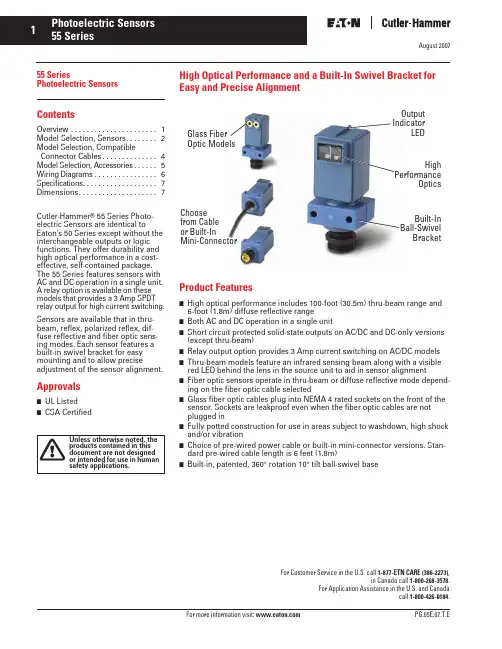
August 20071For more information visit: PG.05E.07.T.E55 SeriesPhotoelectric SensorsContentsOverview . . . . . . . . . . . . . . . . . . . . . . 1 Model Selection, Sensors. . . . . . . . 2 Model Selection, CompatibleConnector Cables. . . . . . . . . . . . . .4Model Selection, Accessories. . . . . .5Wiring Diagrams . . . . . . . . . . . . . . . .6Specifications. . . . . . . . . . . . . . . . . . .7Dimensions. . . . . . . . . . . . . . . . . . . .7Cutler-Hammer ® 55 Series Photo-electric Sensors are identical toEaton’s 50 Series except without the interchangeable outputs or logic functions. They offer durability and high optical performance in a cost-effective, self-contained package. The 55 Series features sensors with AC and DC operation in a single unit. A relay option is available on these models that provides a 3 Amp SPDT relay output for high current switching.Sensors are available that in thru-beam, reflex, polarized reflex, dif-fuse reflective and fiber optic sens-ing modes. Each sensor features a built-in swivel bracket for easy mounting and to allow preciseadjustment of the sensor alignment.Approvals■ UL Listed ■CSA CertifiedHigh Optical Performance and a Built-In Swivel Bracket for Easy and Precise AlignmentProduct Features■ High optical performance includes 100-foot (30.5m) thru-beam range and 6-foot (1.8m) diffuse reflective range■ Both AC and DC operation in a single unit■ Short circuit protected solid-state outputs on AC/DC and DC-only versions (except thru-beam)■ Relay output option provides 3 Amp current switching on AC/DC models ■ Thru-beam models feature an infrared sensing beam along with a visible red LED behind the lens in the source unit to aid in sensor alignment■ Fiber optic sensors operate in thru-beam or diffuse reflective mode depend-ing on the fiber optic cable selected■Glass fiber optic cables plug into NEMA 4 rated sockets on the front of the sensor. Sockets are leakproof even when the fiber optic cables are not plugged in■Fully potted construction for use in areas subject to washdown, high shock and/or vibration■ Choice of pre-wired power cable or built-in mini-connector versions. Stan-dard pre-wired cable length is 6 feet (1.8m)■Built-in, patented, 360° rotation 10° tilt ball-swivel baseFor Customer Service in the U.S. call 1-877-ETN CARE (386-2273) ,in Canada call 1-800-268-3578 .For Application Assistance in the U.S. and Canadacall 1-800-426-9184.Glass Fiber Optic ModelsOutput IndicatorLEDChoose from Cable or Built-InMini-ConnectorHighPerformanceOpticsBuilt-In Ball-Swivel BracketAugust 2007For more information visit: 2Model Selection — SensorsRanges based on 3-inch retroreflector for reflex sensors, 90% reflectance white card for diffuse reflective sensors. ᕄSee Excess Gain graphs on Page 4 .See listing of compatible connector cables on Page 4 .SourceDetectorMinimum object size is 0.4 x 0.7 Inches (10 x 18 mm)Retroreflector (Not Included)SensorFor a complete system,order Sensor and Retroreflector (See PG.05E.17.T.E )3For more information visit: August 2007Model Selection — Sensors (Continued)Ranges based on 3-inch retroreflector for reflex sensors, 90% reflectance white card for diffuse reflective sensors.ᕄ See Excess Gain graphs on Page 4.ᕅ Polarized sensors may not operate with retroreflective tape. Test selected tape before installation.ᕆRanges using standard 0.125-inch diameter fiber optic cable.See listing of compatible connector cables on Page 4.Relay output option for AC/DC Models only (built-to-order, contact factory for delivery lead times). For a 3 Amp, SPDT relay output replace A in Catalog Number with R . (AC/DC Models only — not available in Thru-Beam).SensorFor a complete system,order Sensor and Retroreflector (See PG.05E.17.T.E )Retroreflector (Not Included)Glass Fiber Optic CablesNot Included (See PG.05E.15.T.E )For more information visit: 4August 2007Excess GainModel Selection — Compatible Connector Cables ᕃFor a full selection of connector cables, see PG.05.05.T.E .1.1255A detectors using 1155A sources2.1256A detectors using 1155A sources(90% reflective white card)1.1357A 2.1356A 3.1355A(3-inch diameter retroreflector)1.1455A 2.1456Afiber optic cable shown)1.Thru-Beam mode2.Diffuse reflective mode (90% reflective white card)Current Rating @ 600V 3-pin: 13AMini StyleStraight Female5For more information visit: August 2007Model Selection — AccessoriesAdapter Plate1.00 (25.4)Typ.BCA 0.30(7.6)6 August 2007Wiring Diagrams (Pin numbers are for reference only, rely on pin location when wiring)For more information visit: August 20077For more information visit: SpecificationsApproximate Dimensions in Inches (mm)Thru-Beam All Other Models 115V AC Models230V AC Models10 – 30V DC ModelsAC/DC Models10 – 30V DC ModelsInput Voltage90 – 132V AC, 60 Hz 100 – 132V AC, 50 Hz 180 – 264V AC, 60 Hz 200 – 264V AC, 50 Hz10 – 30V DC, 35 mA 20 – 264V AC, 50/60 Hz or 15 – 30V DC 10 – 30V DC, 35 mA Power Dissipation 2W 2W1W2W1WOperating Temperature -22° to +158°F (-30° to +70°C)-40° to +158°F (-40° to +70°C)Output:VMOS, 50 mA maximum resistive or relay-load; Off-Stage leakage is 0.1 mA maximum Sink/source/TTL,open collectortransistor, 50 mAmaximum load currentStandard Versions:VMOS, 300 mA max./NPN, 300 mA max.Relay Output Versions:3A SPDT relay NPN: 250 mA max., 1.8V drop max.PNP: 100 mA max., 2.6V drop max. (not TTL compatible)Optional Relay Models: SPDT 3A contact Response Times Dark-to-Light: 5 mS Light-to-Dark: 11 mS10 mS1 mSShort Circuit Protection—Sensor will turn off immediately when a short or overload is detected (indicator LED will flash). Turn power OFF and back ON to reset. IMPORTANT: Duringinstallation, correct power connections must be made first to ensure fail-safe short circuit protection of the outputs.Sensor will turn off immediately when a short or overload is detected (indicator LED will flash). Sensor will reset when short is removed.Sunlight Immunity 100 foot Thru-Beam models: 6,000 foot-candlesAll other models: 10,000 foot-candlesHumidity 95% relative humidity, non-condensingCase Material Noryl ® (avoid exposing to chlorinated, halogenated, or aromatic hydrocarbons)Lens Material NylonVibration 15g or 0.06 inch displacement, whichever is less, over 10 Hz to 2 kHz (relay models: 10g over 10 – 55 Hz)Shock40g for 10 mS and 500g for 2 mS, 1/2 sine wave pulse (20g for relay models)Enclosure RatingsNEMA 1, 3, 4, 6, 12 and 13ᕃᕃNOTE: Our products conform to NEMA tests as indicated, however, some severe washdown applications can exceed these NEMA test specifications. If you have questions about a specific application, contact Eaton’s Cutler-Hammer Sensor Applications Department at 1-800-426-9184.Sensors。
Helios 5 FX DualBeamEnabling breakthrough failure analysis for advanced technology nodesThe Helios 5 Dual Beam platform continues to serve the imaging, analysis, and S/TEM sample preparation applications in the most advanced semiconductor failure analysis, process development and process control laboratories.The Thermo Scientific ™ Helios 5 FX ™ DualBeam continues the Helios legacy to the fifth generation combining the innovative Elstar ™ with UC+ technology electron column for high-resolution and high materials contrast imaging, in-lens S/TEM 4 for 3Å in-situ low kV S/TEM imaging and the superior low kV performing Phoenix ™ ion column for fast, precise and sub-nm damagesample preparation. In addition to the industry leading SEM and FIB columns, the Helios 5 FX incorporates a suite of state-of-the-art technologies which enable simple and consistent sample preparation (for high resolution S/TEM imaging and/or Atom Probe microscopy) on even the most challenging samples.High quality imaging at all landing energiesThe ultra-high brightness electron source on the Helios 5 FX System is equipped with 2nd generation UC technology (UC+) to reduce the beam energy spread below 0.2 eV for beam currents up to 100 pA. This enables sub-nanometer resolution and high surface sensitivity at low landing energies. The highly efficient Mirror Detector and In-Column Detector in the Helios 5 FX System come with the ability to simultaneously acquire and mix TLD-SE, MD-BSE and ICD-BSE signals to produce the best overall ultra-high resolution images. Low-loss MD-BSE provides excellent materials contrast with an improvement of up to 1.5x in Contrast-to-Noise ratio, while No-loss ICD-BSE provides materials contrast with maximum surface sensitivity.Shorten time to useable dataThe Helios 5 FX System is the world’s first DualBeam toincorporate a TEM-like CompuStage for TEM lamella sample preparation and combine it with an all new In-lens STEM 4 detector to drastically reduce the time to high quality useable data. The integrated CompuStage is independent of the bulk stage and comes with separate X, Y, Z, eucentric 180° alpha tilt and 200° beta tilt axes enabling SEM endpointing on both sides of S/TEM lamella. The accompanying S/TEM rod is compatible with standard 3 mm TEM grids and enables fast grid exchange without breaking vacuum. In addition, the system is equippedDATASHEETHigh-performance Elstar electron column with UC+monochromator technology for sub-nanometer SEM and S/TEM image resolutionExceptional low kV Phoenix ion beam performance enables sub-nm TEM sample preparation damageSharp, refined, and charge-free contrast obtained from up to 5 integrated in-column and below-the-lens detectors MultiChem Gas Delivery System provides the most advanced capabilities for electron and ion beam induced deposition and etching on DualBeamsEasyLift EX Nanomanipulator enables precise, site-specific preparation of ultra-thin TEM lamellae all while promoting high user confidence and yieldSTEM 4 detector provides outstanding resolution and contrast on thin TEM samplesBacked by the Thermo Fisher Scientfic world class knowledge and expertise in advanced failure analysis forDualBeam applicationsFigure 1. TEM sample preparation using the Thermo Scientific iFAST automation software package and extracted using the EasyLift Nanomanipulator.Figure 2. HRSTEM Bright Field image of a 14 nm SRAM Inverter thinned to 15 nm showing both nFET and pFET structures connected with a metal gate.For current certifications, visit /certifications. © 2020 FEI Company. All rights reserved.All trademarks are the property of Thermo Fisher Scientific and its subsidiaries unless otherwise specified. DS0283-EN-07-2020Find out more at /EM-Saleswith a retractable, annular STEM 4 detector which can be used either in standard mode for real-time STEM endpointing (6Å resolution) or in the new In-lens mode for ultimate imaging performance (3Å resolution). Both modes support improved materials contrast through the use of Bright Field, Dark Field annular and HAADF segments collecting transmitted electrons simultaneously. A new STEM detector enables diffraction imaging and zone axis alignment (automated or manual), enabling highest resolution and contrast on STEM samples. Extreme high resolution, high contrast imaging of ultra-thin lamella is now possible using 30 kV electrons. Having the ability to complete failure analysis work in the DualBeam without exposing the finished sample to ambient air shortens the time to data and reduces the need for standalone S/TEM systems.High quality ultra-thin TEM sample preparationPreparing high quality, ultra-thin TEM samples requires polishing the sample with very low kV ions to minimize damage to the sample. The Thermo Scientific most advanced Phoenix Focused Ion Beam (FIB) column not only delivers high resolution imaging and milling at 30 kV but now expands unmatched FIB performance down to accelerating voltages as low as 500 V enabling the creation of 7 nm TEM lamella with sub-nm damage layers.Enabling flexibilitySmart Alignments actively maintain the system for optimum performance, ready to deliver the highest performance for all users. Patterning improvements ensure the highest quality depositions at any condition, and an extensive automation suite make the Helios 5 the most advanced DualBeam ever assembled—all backed by the Thermo Fisher expert application and service support. Specifications • Electron source–Schottky thermal field emitter, over 1 year lifetime • Ion source–Gallium liquid metal, 1000 hours • Landing Voltage –20 V – 30 kV SEM –500 V – 30 kV FIB • STEM resolution –6Å Standard mode –3Å In-len mode • SEM resolution–Optimal WD0.6 nm @ 2–15 kV 0.7 nm @ 1 kV1.0 nm @ 500 V with beam deceleration –Coincident WD 0.8 nm @ 15 kV 1.2 nm @ 1 kV• Ion beam resolution at coincident point –4.0 nm @ 30 kV using preferred statistical method –2.5 nm @ 30 kV using selective edge method–500 nm @ 500 V using preferred statistical method • EDS resolution–< 30 nm on thinned samples • Gas Delivery–Integrated MultiChem Gas Delivery System –Up to 6 chemistries can be installed –Up to 2 external gasses can be installed • In situ TEM sample liftout –EasyLift EX Nanomanipulator • Stage–5 axis CompuStage with S/TEM holder, equipped with automated insert/retract mechanism and air lock for fast TEM grid exchange without breaking system vacuum –5 axis all piezo motorized bulk stage with automated Loadlock • Sample types–Wafer pieces, packaged parts, grids • Maximum sample size–70 mm diameter with full travel• Application software–iFAST Developers Kit Professional automation software • User interface–Windows ® 10 GUI with integrated SEM, FIB, GIS, simultaneous patterning and imaging mode –Local language support: Check with your local Thermo Fisher sales representatives for available language packs –Two 24-inch widescreen LCD monitors Key options• MultiChem gas chemistries –Range of deposition and etch chemistries • Software–Auto Slice & View ™ software, Magma CAD Navigation • Hardware –EDS and WDS。
Data SheetCisco Firepower 9300 Security ApplianceThe Cisco Firepower™ 9300 is a scalable, carrier-grade platform designed for service providers and others requiring low latency and exceptional throughput, such as high-performance computing centers and high-frequency transactional environments. With tightly integrated, threat-centric security services from Cisco and its partners, Firepower 9300 lowers integration costs and supports the realization of highly secure, open, and programmable networks.Product OverviewCisco Firepower 9300, the appliance component of Cisco’s scalable and agile security services portfolio, offers a highly secure platform to deliver integrated security services. Cisco’s vision is that consistent security policies should be applied to workloads and data flows across physical, virtual, and cloud environments. This approach tightly integrates leading Cisco and complementary partner security services to facilitate intelligent andhigh-performance security. It is specifically designed to protect the Cisco® Evolved Programmable Network, Cisco Evolved Services Platform and Cisco Application Centric Infrastructure architectures.The Firepower 9300 solution for open and programmable networks eliminates much of the costly integration that organizations have had to do themselves.The Firepower 9300 includes Cisco ASA firewalling and VPN. Application-based distributed denial-of-service (DDoS) mitigation capability with Radware DefensePro and additional best-in-class Cisco and partner security services, including Cisco Firepower Threat Defense: Next-Generation IPS (NGIPS) and Cisco Advanced Malware Protection (AMP), Application Visibility and Control (AVC) and URL Filtering will be made available going forward. Each capability is integrated to ensure cons istent security policy is maintained across the network fabric, with dynamic and automated provisioning of security services.Major Features and BenefitsModularity●Configurable connectivity with modular I/O●Expandable capacity with hot-pluggable security modules●Automated and consistent template-based security policiesCarrier Grade●Low-latency and large flow handling with intelligent flow-offloading capabilities●Best-in-class performance density with high throughput●Optional NEBS-ready security modules●Programmatic orchestration and management of security services with RESTful APIsMultiservice Security●Integrate multiple Cisco and partner security services into a single platform to provide intelligent andscalable security●Stitch services dynamically based on traffic classification to apply only the necessary security services*●Provide visibility and correlation of policy, traffic, and events across multiple services*Firepower includes a hardware chassis that accommodates up to three security modules and offers the following features:●Cisco ASA Software (Stateful Firewall plus VPN)●Firepower Threat Defense comprising Advanced Malware Protection (AMP), Next-Generation IPS (NGIPS),and URL filtering*●Cisco partner ecosystem security services (including Radware DefensePro DDoS attack mitigation)** Available in an upcoming release.Performance SpecificationsTable 1 summarizes the capabilities of the Firepower 9300 appliance along with those of the Firepower 9000 Series security modules.Table 1. Capabilities and Capacities1 Maximum throughput w ith User Datagram P rotocol (UDP) traffic measured under ideal test conditions.2“Multiprotocol” refers to a traffi c profile consisting primarily of TCP-based protocols and applications like HTTP, SMTP, FTP, IMAP v4, BitTorrent, and DNS.3 Available for the firew all feature set.Hardware SpecificationsTable 2 summarizes the specifications for the Firepower 9300 appliance. Table 3 summarizes regulatory standards compliance.Table 2. Firepow er 9300 Hardw are Specifications** Scheduled to be supported in Q3 CY2015Table 3. Regulatory Standards Compliance: Safety and E MCOrdering InformationTable 4. P roduct Component Ordering GuideWarranty InformationFind warranty information on at the Product Warranties page.Cisco ServicesCisco offers a wide range of service programs to accelerate customer success. These innovative services programs are delivered through a unique combination of people, processes, tools, and partners, resulting in high levels of customer satisfaction. Cisco Services help you protect your network investment, optimize network operations, and prepare your network for new applications to extend network intelligence and the power of your business. For more information about Cisco services for security, visit /go/services/security.Cisco CapitalFinancing to Help You Achieve Your ObjectivesCisco Capital® can help you acquire the technology you need to achieve your objectives and stay competitive. We can help you reduce CapEx. Accelerate your growth. Optimize your investment dollars and ROI. Cisco Capital financing gives you flexibility in acquiring hardware, software, services, and complementary third-party equipment. And there’s just one predictable payment. Cisco Capital is available in more than 100 countries. Learn more.For More InformationFor more information about the Cisco Firepower 9000 Series Security Platform visit●/c/en/us/solutions/enterprise-networks/service-provider-security-solutions/。
3GPP TS 36.331 V13.2.0 (2016-06)Technical Specification3rd Generation Partnership Project;Technical Specification Group Radio Access Network;Evolved Universal Terrestrial Radio Access (E-UTRA);Radio Resource Control (RRC);Protocol specification(Release 13)The present document has been developed within the 3rd Generation Partnership Project (3GPP TM) and may be further elaborated for the purposes of 3GPP. The present document has not been subject to any approval process by the 3GPP Organizational Partners and shall not be implemented.This Specification is provided for future development work within 3GPP only. The Organizational Partners accept no liability for any use of this Specification. Specifications and reports for implementation of the 3GPP TM system should be obtained via the 3GPP Organizational Partners' Publications Offices.KeywordsUMTS, radio3GPPPostal address3GPP support office address650 Route des Lucioles - Sophia AntipolisValbonne - FRANCETel.: +33 4 92 94 42 00 Fax: +33 4 93 65 47 16InternetCopyright NotificationNo part may be reproduced except as authorized by written permission.The copyright and the foregoing restriction extend to reproduction in all media.© 2016, 3GPP Organizational Partners (ARIB, ATIS, CCSA, ETSI, TSDSI, TTA, TTC).All rights reserved.UMTS™ is a Trade Mark of ETSI registered for the benefit of its members3GPP™ is a Trade Mark of ETSI registered for the benefit of its Members and of the 3GPP Organizational PartnersLTE™ is a Trade Mark of ETSI currently being registered for the benefit of its Members and of the 3GPP Organizational Partners GSM® and the GSM logo are registered and owned by the GSM AssociationBluetooth® is a Trade Mark of the Bluetooth SIG registered for the benefit of its membersContentsForeword (18)1Scope (19)2References (19)3Definitions, symbols and abbreviations (22)3.1Definitions (22)3.2Abbreviations (24)4General (27)4.1Introduction (27)4.2Architecture (28)4.2.1UE states and state transitions including inter RAT (28)4.2.2Signalling radio bearers (29)4.3Services (30)4.3.1Services provided to upper layers (30)4.3.2Services expected from lower layers (30)4.4Functions (30)5Procedures (32)5.1General (32)5.1.1Introduction (32)5.1.2General requirements (32)5.2System information (33)5.2.1Introduction (33)5.2.1.1General (33)5.2.1.2Scheduling (34)5.2.1.2a Scheduling for NB-IoT (34)5.2.1.3System information validity and notification of changes (35)5.2.1.4Indication of ETWS notification (36)5.2.1.5Indication of CMAS notification (37)5.2.1.6Notification of EAB parameters change (37)5.2.1.7Access Barring parameters change in NB-IoT (37)5.2.2System information acquisition (38)5.2.2.1General (38)5.2.2.2Initiation (38)5.2.2.3System information required by the UE (38)5.2.2.4System information acquisition by the UE (39)5.2.2.5Essential system information missing (42)5.2.2.6Actions upon reception of the MasterInformationBlock message (42)5.2.2.7Actions upon reception of the SystemInformationBlockType1 message (42)5.2.2.8Actions upon reception of SystemInformation messages (44)5.2.2.9Actions upon reception of SystemInformationBlockType2 (44)5.2.2.10Actions upon reception of SystemInformationBlockType3 (45)5.2.2.11Actions upon reception of SystemInformationBlockType4 (45)5.2.2.12Actions upon reception of SystemInformationBlockType5 (45)5.2.2.13Actions upon reception of SystemInformationBlockType6 (45)5.2.2.14Actions upon reception of SystemInformationBlockType7 (45)5.2.2.15Actions upon reception of SystemInformationBlockType8 (45)5.2.2.16Actions upon reception of SystemInformationBlockType9 (46)5.2.2.17Actions upon reception of SystemInformationBlockType10 (46)5.2.2.18Actions upon reception of SystemInformationBlockType11 (46)5.2.2.19Actions upon reception of SystemInformationBlockType12 (47)5.2.2.20Actions upon reception of SystemInformationBlockType13 (48)5.2.2.21Actions upon reception of SystemInformationBlockType14 (48)5.2.2.22Actions upon reception of SystemInformationBlockType15 (48)5.2.2.23Actions upon reception of SystemInformationBlockType16 (48)5.2.2.24Actions upon reception of SystemInformationBlockType17 (48)5.2.2.25Actions upon reception of SystemInformationBlockType18 (48)5.2.2.26Actions upon reception of SystemInformationBlockType19 (49)5.2.3Acquisition of an SI message (49)5.2.3a Acquisition of an SI message by BL UE or UE in CE or a NB-IoT UE (50)5.3Connection control (50)5.3.1Introduction (50)5.3.1.1RRC connection control (50)5.3.1.2Security (52)5.3.1.2a RN security (53)5.3.1.3Connected mode mobility (53)5.3.1.4Connection control in NB-IoT (54)5.3.2Paging (55)5.3.2.1General (55)5.3.2.2Initiation (55)5.3.2.3Reception of the Paging message by the UE (55)5.3.3RRC connection establishment (56)5.3.3.1General (56)5.3.3.1a Conditions for establishing RRC Connection for sidelink communication/ discovery (58)5.3.3.2Initiation (59)5.3.3.3Actions related to transmission of RRCConnectionRequest message (63)5.3.3.3a Actions related to transmission of RRCConnectionResumeRequest message (64)5.3.3.4Reception of the RRCConnectionSetup by the UE (64)5.3.3.4a Reception of the RRCConnectionResume by the UE (66)5.3.3.5Cell re-selection while T300, T302, T303, T305, T306, or T308 is running (68)5.3.3.6T300 expiry (68)5.3.3.7T302, T303, T305, T306, or T308 expiry or stop (69)5.3.3.8Reception of the RRCConnectionReject by the UE (70)5.3.3.9Abortion of RRC connection establishment (71)5.3.3.10Handling of SSAC related parameters (71)5.3.3.11Access barring check (72)5.3.3.12EAB check (73)5.3.3.13Access barring check for ACDC (73)5.3.3.14Access Barring check for NB-IoT (74)5.3.4Initial security activation (75)5.3.4.1General (75)5.3.4.2Initiation (76)5.3.4.3Reception of the SecurityModeCommand by the UE (76)5.3.5RRC connection reconfiguration (77)5.3.5.1General (77)5.3.5.2Initiation (77)5.3.5.3Reception of an RRCConnectionReconfiguration not including the mobilityControlInfo by theUE (77)5.3.5.4Reception of an RRCConnectionReconfiguration including the mobilityControlInfo by the UE(handover) (79)5.3.5.5Reconfiguration failure (83)5.3.5.6T304 expiry (handover failure) (83)5.3.5.7Void (84)5.3.5.7a T307 expiry (SCG change failure) (84)5.3.5.8Radio Configuration involving full configuration option (84)5.3.6Counter check (86)5.3.6.1General (86)5.3.6.2Initiation (86)5.3.6.3Reception of the CounterCheck message by the UE (86)5.3.7RRC connection re-establishment (87)5.3.7.1General (87)5.3.7.2Initiation (87)5.3.7.3Actions following cell selection while T311 is running (88)5.3.7.4Actions related to transmission of RRCConnectionReestablishmentRequest message (89)5.3.7.5Reception of the RRCConnectionReestablishment by the UE (89)5.3.7.6T311 expiry (91)5.3.7.7T301 expiry or selected cell no longer suitable (91)5.3.7.8Reception of RRCConnectionReestablishmentReject by the UE (91)5.3.8RRC connection release (92)5.3.8.1General (92)5.3.8.2Initiation (92)5.3.8.3Reception of the RRCConnectionRelease by the UE (92)5.3.8.4T320 expiry (93)5.3.9RRC connection release requested by upper layers (93)5.3.9.1General (93)5.3.9.2Initiation (93)5.3.10Radio resource configuration (93)5.3.10.0General (93)5.3.10.1SRB addition/ modification (94)5.3.10.2DRB release (95)5.3.10.3DRB addition/ modification (95)5.3.10.3a1DC specific DRB addition or reconfiguration (96)5.3.10.3a2LWA specific DRB addition or reconfiguration (98)5.3.10.3a3LWIP specific DRB addition or reconfiguration (98)5.3.10.3a SCell release (99)5.3.10.3b SCell addition/ modification (99)5.3.10.3c PSCell addition or modification (99)5.3.10.4MAC main reconfiguration (99)5.3.10.5Semi-persistent scheduling reconfiguration (100)5.3.10.6Physical channel reconfiguration (100)5.3.10.7Radio Link Failure Timers and Constants reconfiguration (101)5.3.10.8Time domain measurement resource restriction for serving cell (101)5.3.10.9Other configuration (102)5.3.10.10SCG reconfiguration (103)5.3.10.11SCG dedicated resource configuration (104)5.3.10.12Reconfiguration SCG or split DRB by drb-ToAddModList (105)5.3.10.13Neighbour cell information reconfiguration (105)5.3.10.14Void (105)5.3.10.15Sidelink dedicated configuration (105)5.3.10.16T370 expiry (106)5.3.11Radio link failure related actions (107)5.3.11.1Detection of physical layer problems in RRC_CONNECTED (107)5.3.11.2Recovery of physical layer problems (107)5.3.11.3Detection of radio link failure (107)5.3.12UE actions upon leaving RRC_CONNECTED (109)5.3.13UE actions upon PUCCH/ SRS release request (110)5.3.14Proximity indication (110)5.3.14.1General (110)5.3.14.2Initiation (111)5.3.14.3Actions related to transmission of ProximityIndication message (111)5.3.15Void (111)5.4Inter-RAT mobility (111)5.4.1Introduction (111)5.4.2Handover to E-UTRA (112)5.4.2.1General (112)5.4.2.2Initiation (112)5.4.2.3Reception of the RRCConnectionReconfiguration by the UE (112)5.4.2.4Reconfiguration failure (114)5.4.2.5T304 expiry (handover to E-UTRA failure) (114)5.4.3Mobility from E-UTRA (114)5.4.3.1General (114)5.4.3.2Initiation (115)5.4.3.3Reception of the MobilityFromEUTRACommand by the UE (115)5.4.3.4Successful completion of the mobility from E-UTRA (116)5.4.3.5Mobility from E-UTRA failure (117)5.4.4Handover from E-UTRA preparation request (CDMA2000) (117)5.4.4.1General (117)5.4.4.2Initiation (118)5.4.4.3Reception of the HandoverFromEUTRAPreparationRequest by the UE (118)5.4.5UL handover preparation transfer (CDMA2000) (118)5.4.5.1General (118)5.4.5.2Initiation (118)5.4.5.3Actions related to transmission of the ULHandoverPreparationTransfer message (119)5.4.5.4Failure to deliver the ULHandoverPreparationTransfer message (119)5.4.6Inter-RAT cell change order to E-UTRAN (119)5.4.6.1General (119)5.4.6.2Initiation (119)5.4.6.3UE fails to complete an inter-RAT cell change order (119)5.5Measurements (120)5.5.1Introduction (120)5.5.2Measurement configuration (121)5.5.2.1General (121)5.5.2.2Measurement identity removal (122)5.5.2.2a Measurement identity autonomous removal (122)5.5.2.3Measurement identity addition/ modification (123)5.5.2.4Measurement object removal (124)5.5.2.5Measurement object addition/ modification (124)5.5.2.6Reporting configuration removal (126)5.5.2.7Reporting configuration addition/ modification (127)5.5.2.8Quantity configuration (127)5.5.2.9Measurement gap configuration (127)5.5.2.10Discovery signals measurement timing configuration (128)5.5.2.11RSSI measurement timing configuration (128)5.5.3Performing measurements (128)5.5.3.1General (128)5.5.3.2Layer 3 filtering (131)5.5.4Measurement report triggering (131)5.5.4.1General (131)5.5.4.2Event A1 (Serving becomes better than threshold) (135)5.5.4.3Event A2 (Serving becomes worse than threshold) (136)5.5.4.4Event A3 (Neighbour becomes offset better than PCell/ PSCell) (136)5.5.4.5Event A4 (Neighbour becomes better than threshold) (137)5.5.4.6Event A5 (PCell/ PSCell becomes worse than threshold1 and neighbour becomes better thanthreshold2) (138)5.5.4.6a Event A6 (Neighbour becomes offset better than SCell) (139)5.5.4.7Event B1 (Inter RAT neighbour becomes better than threshold) (139)5.5.4.8Event B2 (PCell becomes worse than threshold1 and inter RAT neighbour becomes better thanthreshold2) (140)5.5.4.9Event C1 (CSI-RS resource becomes better than threshold) (141)5.5.4.10Event C2 (CSI-RS resource becomes offset better than reference CSI-RS resource) (141)5.5.4.11Event W1 (WLAN becomes better than a threshold) (142)5.5.4.12Event W2 (All WLAN inside WLAN mobility set becomes worse than threshold1 and a WLANoutside WLAN mobility set becomes better than threshold2) (142)5.5.4.13Event W3 (All WLAN inside WLAN mobility set becomes worse than a threshold) (143)5.5.5Measurement reporting (144)5.5.6Measurement related actions (148)5.5.6.1Actions upon handover and re-establishment (148)5.5.6.2Speed dependant scaling of measurement related parameters (149)5.5.7Inter-frequency RSTD measurement indication (149)5.5.7.1General (149)5.5.7.2Initiation (150)5.5.7.3Actions related to transmission of InterFreqRSTDMeasurementIndication message (150)5.6Other (150)5.6.0General (150)5.6.1DL information transfer (151)5.6.1.1General (151)5.6.1.2Initiation (151)5.6.1.3Reception of the DLInformationTransfer by the UE (151)5.6.2UL information transfer (151)5.6.2.1General (151)5.6.2.2Initiation (151)5.6.2.3Actions related to transmission of ULInformationTransfer message (152)5.6.2.4Failure to deliver ULInformationTransfer message (152)5.6.3UE capability transfer (152)5.6.3.1General (152)5.6.3.2Initiation (153)5.6.3.3Reception of the UECapabilityEnquiry by the UE (153)5.6.4CSFB to 1x Parameter transfer (157)5.6.4.1General (157)5.6.4.2Initiation (157)5.6.4.3Actions related to transmission of CSFBParametersRequestCDMA2000 message (157)5.6.4.4Reception of the CSFBParametersResponseCDMA2000 message (157)5.6.5UE Information (158)5.6.5.1General (158)5.6.5.2Initiation (158)5.6.5.3Reception of the UEInformationRequest message (158)5.6.6 Logged Measurement Configuration (159)5.6.6.1General (159)5.6.6.2Initiation (160)5.6.6.3Reception of the LoggedMeasurementConfiguration by the UE (160)5.6.6.4T330 expiry (160)5.6.7 Release of Logged Measurement Configuration (160)5.6.7.1General (160)5.6.7.2Initiation (160)5.6.8 Measurements logging (161)5.6.8.1General (161)5.6.8.2Initiation (161)5.6.9In-device coexistence indication (163)5.6.9.1General (163)5.6.9.2Initiation (164)5.6.9.3Actions related to transmission of InDeviceCoexIndication message (164)5.6.10UE Assistance Information (165)5.6.10.1General (165)5.6.10.2Initiation (166)5.6.10.3Actions related to transmission of UEAssistanceInformation message (166)5.6.11 Mobility history information (166)5.6.11.1General (166)5.6.11.2Initiation (166)5.6.12RAN-assisted WLAN interworking (167)5.6.12.1General (167)5.6.12.2Dedicated WLAN offload configuration (167)5.6.12.3WLAN offload RAN evaluation (167)5.6.12.4T350 expiry or stop (167)5.6.12.5Cell selection/ re-selection while T350 is running (168)5.6.13SCG failure information (168)5.6.13.1General (168)5.6.13.2Initiation (168)5.6.13.3Actions related to transmission of SCGFailureInformation message (168)5.6.14LTE-WLAN Aggregation (169)5.6.14.1Introduction (169)5.6.14.2Reception of LWA configuration (169)5.6.14.3Release of LWA configuration (170)5.6.15WLAN connection management (170)5.6.15.1Introduction (170)5.6.15.2WLAN connection status reporting (170)5.6.15.2.1General (170)5.6.15.2.2Initiation (171)5.6.15.2.3Actions related to transmission of WLANConnectionStatusReport message (171)5.6.15.3T351 Expiry (WLAN connection attempt timeout) (171)5.6.15.4WLAN status monitoring (171)5.6.16RAN controlled LTE-WLAN interworking (172)5.6.16.1General (172)5.6.16.2WLAN traffic steering command (172)5.6.17LTE-WLAN aggregation with IPsec tunnel (173)5.6.17.1General (173)5.7Generic error handling (174)5.7.1General (174)5.7.2ASN.1 violation or encoding error (174)5.7.3Field set to a not comprehended value (174)5.7.4Mandatory field missing (174)5.7.5Not comprehended field (176)5.8MBMS (176)5.8.1Introduction (176)5.8.1.1General (176)5.8.1.2Scheduling (176)5.8.1.3MCCH information validity and notification of changes (176)5.8.2MCCH information acquisition (178)5.8.2.1General (178)5.8.2.2Initiation (178)5.8.2.3MCCH information acquisition by the UE (178)5.8.2.4Actions upon reception of the MBSFNAreaConfiguration message (178)5.8.2.5Actions upon reception of the MBMSCountingRequest message (179)5.8.3MBMS PTM radio bearer configuration (179)5.8.3.1General (179)5.8.3.2Initiation (179)5.8.3.3MRB establishment (179)5.8.3.4MRB release (179)5.8.4MBMS Counting Procedure (179)5.8.4.1General (179)5.8.4.2Initiation (180)5.8.4.3Reception of the MBMSCountingRequest message by the UE (180)5.8.5MBMS interest indication (181)5.8.5.1General (181)5.8.5.2Initiation (181)5.8.5.3Determine MBMS frequencies of interest (182)5.8.5.4Actions related to transmission of MBMSInterestIndication message (183)5.8a SC-PTM (183)5.8a.1Introduction (183)5.8a.1.1General (183)5.8a.1.2SC-MCCH scheduling (183)5.8a.1.3SC-MCCH information validity and notification of changes (183)5.8a.1.4Procedures (184)5.8a.2SC-MCCH information acquisition (184)5.8a.2.1General (184)5.8a.2.2Initiation (184)5.8a.2.3SC-MCCH information acquisition by the UE (184)5.8a.2.4Actions upon reception of the SCPTMConfiguration message (185)5.8a.3SC-PTM radio bearer configuration (185)5.8a.3.1General (185)5.8a.3.2Initiation (185)5.8a.3.3SC-MRB establishment (185)5.8a.3.4SC-MRB release (185)5.9RN procedures (186)5.9.1RN reconfiguration (186)5.9.1.1General (186)5.9.1.2Initiation (186)5.9.1.3Reception of the RNReconfiguration by the RN (186)5.10Sidelink (186)5.10.1Introduction (186)5.10.1a Conditions for sidelink communication operation (187)5.10.2Sidelink UE information (188)5.10.2.1General (188)5.10.2.2Initiation (189)5.10.2.3Actions related to transmission of SidelinkUEInformation message (193)5.10.3Sidelink communication monitoring (195)5.10.6Sidelink discovery announcement (198)5.10.6a Sidelink discovery announcement pool selection (201)5.10.6b Sidelink discovery announcement reference carrier selection (201)5.10.7Sidelink synchronisation information transmission (202)5.10.7.1General (202)5.10.7.2Initiation (203)5.10.7.3Transmission of SLSS (204)5.10.7.4Transmission of MasterInformationBlock-SL message (205)5.10.7.5Void (206)5.10.8Sidelink synchronisation reference (206)5.10.8.1General (206)5.10.8.2Selection and reselection of synchronisation reference UE (SyncRef UE) (206)5.10.9Sidelink common control information (207)5.10.9.1General (207)5.10.9.2Actions related to reception of MasterInformationBlock-SL message (207)5.10.10Sidelink relay UE operation (207)5.10.10.1General (207)5.10.10.2AS-conditions for relay related sidelink communication transmission by sidelink relay UE (207)5.10.10.3AS-conditions for relay PS related sidelink discovery transmission by sidelink relay UE (208)5.10.10.4Sidelink relay UE threshold conditions (208)5.10.11Sidelink remote UE operation (208)5.10.11.1General (208)5.10.11.2AS-conditions for relay related sidelink communication transmission by sidelink remote UE (208)5.10.11.3AS-conditions for relay PS related sidelink discovery transmission by sidelink remote UE (209)5.10.11.4Selection and reselection of sidelink relay UE (209)5.10.11.5Sidelink remote UE threshold conditions (210)6Protocol data units, formats and parameters (tabular & ASN.1) (210)6.1General (210)6.2RRC messages (212)6.2.1General message structure (212)–EUTRA-RRC-Definitions (212)–BCCH-BCH-Message (212)–BCCH-DL-SCH-Message (212)–BCCH-DL-SCH-Message-BR (213)–MCCH-Message (213)–PCCH-Message (213)–DL-CCCH-Message (214)–DL-DCCH-Message (214)–UL-CCCH-Message (214)–UL-DCCH-Message (215)–SC-MCCH-Message (215)6.2.2Message definitions (216)–CounterCheck (216)–CounterCheckResponse (217)–CSFBParametersRequestCDMA2000 (217)–CSFBParametersResponseCDMA2000 (218)–DLInformationTransfer (218)–HandoverFromEUTRAPreparationRequest (CDMA2000) (219)–InDeviceCoexIndication (220)–InterFreqRSTDMeasurementIndication (222)–LoggedMeasurementConfiguration (223)–MasterInformationBlock (225)–MBMSCountingRequest (226)–MBMSCountingResponse (226)–MBMSInterestIndication (227)–MBSFNAreaConfiguration (228)–MeasurementReport (228)–MobilityFromEUTRACommand (229)–Paging (232)–ProximityIndication (233)–RNReconfiguration (234)–RNReconfigurationComplete (234)–RRCConnectionReconfiguration (235)–RRCConnectionReconfigurationComplete (240)–RRCConnectionReestablishment (241)–RRCConnectionReestablishmentComplete (241)–RRCConnectionReestablishmentReject (242)–RRCConnectionReestablishmentRequest (243)–RRCConnectionReject (243)–RRCConnectionRelease (244)–RRCConnectionResume (248)–RRCConnectionResumeComplete (249)–RRCConnectionResumeRequest (250)–RRCConnectionRequest (250)–RRCConnectionSetup (251)–RRCConnectionSetupComplete (252)–SCGFailureInformation (253)–SCPTMConfiguration (254)–SecurityModeCommand (255)–SecurityModeComplete (255)–SecurityModeFailure (256)–SidelinkUEInformation (256)–SystemInformation (258)–SystemInformationBlockType1 (259)–UEAssistanceInformation (264)–UECapabilityEnquiry (265)–UECapabilityInformation (266)–UEInformationRequest (267)–UEInformationResponse (267)–ULHandoverPreparationTransfer (CDMA2000) (273)–ULInformationTransfer (274)–WLANConnectionStatusReport (274)6.3RRC information elements (275)6.3.1System information blocks (275)–SystemInformationBlockType2 (275)–SystemInformationBlockType3 (279)–SystemInformationBlockType4 (282)–SystemInformationBlockType5 (283)–SystemInformationBlockType6 (287)–SystemInformationBlockType7 (289)–SystemInformationBlockType8 (290)–SystemInformationBlockType9 (295)–SystemInformationBlockType10 (295)–SystemInformationBlockType11 (296)–SystemInformationBlockType12 (297)–SystemInformationBlockType13 (297)–SystemInformationBlockType14 (298)–SystemInformationBlockType15 (298)–SystemInformationBlockType16 (299)–SystemInformationBlockType17 (300)–SystemInformationBlockType18 (301)–SystemInformationBlockType19 (301)–SystemInformationBlockType20 (304)6.3.2Radio resource control information elements (304)–AntennaInfo (304)–AntennaInfoUL (306)–CQI-ReportConfig (307)–CQI-ReportPeriodicProcExtId (314)–CrossCarrierSchedulingConfig (314)–CSI-IM-Config (315)–CSI-IM-ConfigId (315)–CSI-RS-Config (317)–CSI-RS-ConfigEMIMO (318)–CSI-RS-ConfigNZP (319)–CSI-RS-ConfigNZPId (320)–CSI-RS-ConfigZP (321)–CSI-RS-ConfigZPId (321)–DMRS-Config (321)–DRB-Identity (322)–EPDCCH-Config (322)–EIMTA-MainConfig (324)–LogicalChannelConfig (325)–LWA-Configuration (326)–LWIP-Configuration (326)–RCLWI-Configuration (327)–MAC-MainConfig (327)–P-C-AndCBSR (332)–PDCCH-ConfigSCell (333)–PDCP-Config (334)–PDSCH-Config (337)–PDSCH-RE-MappingQCL-ConfigId (339)–PHICH-Config (339)–PhysicalConfigDedicated (339)–P-Max (344)–PRACH-Config (344)–PresenceAntennaPort1 (346)–PUCCH-Config (347)–PUSCH-Config (351)–RACH-ConfigCommon (355)–RACH-ConfigDedicated (357)–RadioResourceConfigCommon (358)–RadioResourceConfigDedicated (362)–RLC-Config (367)–RLF-TimersAndConstants (369)–RN-SubframeConfig (370)–SchedulingRequestConfig (371)–SoundingRS-UL-Config (372)–SPS-Config (375)–TDD-Config (376)–TimeAlignmentTimer (377)–TPC-PDCCH-Config (377)–TunnelConfigLWIP (378)–UplinkPowerControl (379)–WLAN-Id-List (382)–WLAN-MobilityConfig (382)6.3.3Security control information elements (382)–NextHopChainingCount (382)–SecurityAlgorithmConfig (383)–ShortMAC-I (383)6.3.4Mobility control information elements (383)–AdditionalSpectrumEmission (383)–ARFCN-ValueCDMA2000 (383)–ARFCN-ValueEUTRA (384)–ARFCN-ValueGERAN (384)–ARFCN-ValueUTRA (384)–BandclassCDMA2000 (384)–BandIndicatorGERAN (385)–CarrierFreqCDMA2000 (385)–CarrierFreqGERAN (385)–CellIndexList (387)–CellReselectionPriority (387)–CellSelectionInfoCE (387)–CellReselectionSubPriority (388)–CSFB-RegistrationParam1XRTT (388)–CellGlobalIdEUTRA (389)–CellGlobalIdUTRA (389)–CellGlobalIdGERAN (390)–CellGlobalIdCDMA2000 (390)–CellSelectionInfoNFreq (391)–CSG-Identity (391)–FreqBandIndicator (391)–MobilityControlInfo (391)–MobilityParametersCDMA2000 (1xRTT) (393)–MobilityStateParameters (394)–MultiBandInfoList (394)–NS-PmaxList (394)–PhysCellId (395)–PhysCellIdRange (395)–PhysCellIdRangeUTRA-FDDList (395)–PhysCellIdCDMA2000 (396)–PhysCellIdGERAN (396)–PhysCellIdUTRA-FDD (396)–PhysCellIdUTRA-TDD (396)–PLMN-Identity (397)–PLMN-IdentityList3 (397)–PreRegistrationInfoHRPD (397)–Q-QualMin (398)–Q-RxLevMin (398)–Q-OffsetRange (398)–Q-OffsetRangeInterRAT (399)–ReselectionThreshold (399)–ReselectionThresholdQ (399)–SCellIndex (399)–ServCellIndex (400)–SpeedStateScaleFactors (400)–SystemInfoListGERAN (400)–SystemTimeInfoCDMA2000 (401)–TrackingAreaCode (401)–T-Reselection (402)–T-ReselectionEUTRA-CE (402)6.3.5Measurement information elements (402)–AllowedMeasBandwidth (402)–CSI-RSRP-Range (402)–Hysteresis (402)–LocationInfo (403)–MBSFN-RSRQ-Range (403)–MeasConfig (404)–MeasDS-Config (405)–MeasGapConfig (406)–MeasId (407)–MeasIdToAddModList (407)–MeasObjectCDMA2000 (408)–MeasObjectEUTRA (408)–MeasObjectGERAN (412)–MeasObjectId (412)–MeasObjectToAddModList (412)–MeasObjectUTRA (413)–ReportConfigEUTRA (422)–ReportConfigId (425)–ReportConfigInterRAT (425)–ReportConfigToAddModList (428)–ReportInterval (429)–RSRP-Range (429)–RSRQ-Range (430)–RSRQ-Type (430)–RS-SINR-Range (430)–RSSI-Range-r13 (431)–TimeToTrigger (431)–UL-DelayConfig (431)–WLAN-CarrierInfo (431)–WLAN-RSSI-Range (432)–WLAN-Status (432)6.3.6Other information elements (433)–AbsoluteTimeInfo (433)–AreaConfiguration (433)–C-RNTI (433)–DedicatedInfoCDMA2000 (434)–DedicatedInfoNAS (434)–FilterCoefficient (434)–LoggingDuration (434)–LoggingInterval (435)–MeasSubframePattern (435)–MMEC (435)–NeighCellConfig (435)–OtherConfig (436)–RAND-CDMA2000 (1xRTT) (437)–RAT-Type (437)–ResumeIdentity (437)–RRC-TransactionIdentifier (438)–S-TMSI (438)–TraceReference (438)–UE-CapabilityRAT-ContainerList (438)–UE-EUTRA-Capability (439)–UE-RadioPagingInfo (469)–UE-TimersAndConstants (469)–VisitedCellInfoList (470)–WLAN-OffloadConfig (470)6.3.7MBMS information elements (472)–MBMS-NotificationConfig (472)–MBMS-ServiceList (473)–MBSFN-AreaId (473)–MBSFN-AreaInfoList (473)–MBSFN-SubframeConfig (474)–PMCH-InfoList (475)6.3.7a SC-PTM information elements (476)–SC-MTCH-InfoList (476)–SCPTM-NeighbourCellList (478)6.3.8Sidelink information elements (478)–SL-CommConfig (478)–SL-CommResourcePool (479)–SL-CP-Len (480)–SL-DiscConfig (481)–SL-DiscResourcePool (483)–SL-DiscTxPowerInfo (485)–SL-GapConfig (485)。

Product informationISOFLEX NBU 15,Prod. 004026,enEdition 16.07.2016 [replaces edition 26.12.2015]Benefits for your application–Tried and tested over many years especially in high-speed applications–Longer component life due to optimized wear protection and good pressure absorption capacity–Excellent resistance to water and media as well as above-average anticorrosive additives protect bearings against premature failure, thus helping to minimize repair costs–Low intrinsic bearing heat due to low lubricant friction enabling longer service life–Uninterrupted machine operation due to good pumpability and metering in customary centralized lubricating systemsDescriptionISOFLEX NBU 15 is a high-speed grease with a good pressure absorption capacity.It consists of a combination of ester oil, synthetic hydrocarbon oil and mineral oil and a barium complex soap. It offers good protection against wear and corrosion and is resistant to water,media and oxidation.ApplicationISOFLEX NBU 15 is primarily used for spindle bearings and high-speed plain bearings, e.g. in machine tools and textile machines. Further applications are in threaded spindles, ball screws operating under high loads, running gear bearings, as a long-term grease in cableway bearings and in precision engineering. It may also be used for the lubrication of tooth flanks in precision gears (e.g. bevel gears in milling machines,electromechanical valve actuators).Application notesThe lubricant is applied by brush, spatula, grease gun or grease cartridge. Owing to the many elastomer and plastic compositions, we recommend checking the grease'scompatibility prior to series application with elastomers or plastics.Material safety data sheetsMaterial safety data sheets can be requested via our website . You may also obtain them through your contact person at Klüber Lubrication.Product information。
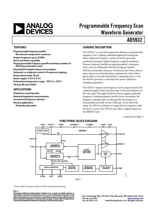
Programmable Frequency ScanWaveform GeneratorAD5932Rev. 0Information furnished by Analog Devices is believed to be accurate and reliable. However , noresponsibility is assumed by Analog Devices for its use, nor for any infringements of patents or other rights of third parties that may result from its use. Specifications subject to change without notice. No license is granted by implication or otherwise under any patent or patent rights of Analog Devices. T rademarks and registered trademarks are the property of their respective owners.One Technology Way, P.O. Box 9106, N orwood, MA 02062-9106, U.S.A.Tel: 781.329.4700 Fax: 781.461.3113 ©2006 Analog Devices, Inc. All rights reserved.FEATURESGENERAL DESCRIPTIONProgrammable frequency profileThe AD59321 is a waveform generator offering a programmable frequency scan. Utilizing embedded digital processing that allows enhanced frequency control, the device generates synthesized analog or digital frequency-stepped waveforms. Because frequency profiles are preprogrammed, continuous write cycles are eliminated, thereby freeing up valuableDSP/microcontroller resources. Waveforms start from a known phase and are incremented phase-continuously, which allows phase shifts to be easily determined. Consuming only 6.7 mA, the AD5932 provides a convenient low power solution to waveform generation.No external components necessary Output frequency up to 25 MHz Burst-and-listen capabilityPreprogrammable frequency profile minimizes number of DSP/microcontroller writesSinusoidal/triangular/square wave outputsAutomatic or single pin control of frequency stepping Power-down mode: 20 μA Power supply: 2.3 V to 5.5 VAutomotive temperature range: −40°C to +125°C 16-lead, Pb-free TSSOPThe AD5932 outputs each frequency in the range of interest for a defined length of time and then steps to the next frequency in the scan range. The length of time the device outputs a particular frequency is preprogrammed, and the device increments the frequency automatically; or, alternatively, the frequency is incremented externally via the CTRL pin. At the end of the range, the AD5932 continues to output the last frequency until the device is reset. The AD5932 also offers a digital output via the MSBOUT pin.APPLICATIONSFrequency scanning/radarNetwork/impedance measurements Incremental frequency stimulus Sensory applications Proximity and motion(continued on Page 3)FUNCTIONAL BLOCK DIAGRAMMCLKCTRLSYNCOUTMSBOUTVOUTCOMP05416-001Figure 1.1Protected by U.S. patent number 6747583; other patents pending.AD5932Rev. 0 | Page 2 of 28TABLE OF CONTENTSFeatures..............................................................................................1 Applications.......................................................................................1 General Description.........................................................................1 Functional Block Diagram..............................................................1 Revision History...............................................................................2 Specifications.....................................................................................4 Specifications Test Circuit...........................................................5 Timing Specifications..................................................................6 Master Clock and Timing Diagrams.........................................6 Absolute Maximum Ratings............................................................8 ESD Caution..................................................................................8 Pin Configuration and Function Descriptions.............................9 Typical Performance Characteristics...........................................10 Terminology....................................................................................14 Theory of Operation......................................................................15 Frequency Profile........................................................................15 Serial Interface............................................................................15 Powering up the AD5932..........................................................15 Programming the AD5932........................................................16 Setting Up the Frequency Scan.................................................17 Activating and Controlling the Scan.......................................18 Outputs from the AD5932........................................................19 Applications.....................................................................................20 Grounding and Layout..............................................................20 AD5932 to ADSP-21xx Interface.............................................20 AD5932 to 68HC11/68L11 Interface.......................................21 AD5932 to 80C51/80L51 Interface..........................................21 AD5932 to DSP56002 Interface...............................................21 Evaluation Board............................................................................22 Schematics...................................................................................23 Outline Dimensions.......................................................................25 Ordering Guide.. (25)REVISION HISTORY4/06—Revision 0: Initial VersionAD5932Rev. 0 | Page 3 of 28GENERAL DESCRIPTION(continued from Page 1)To program the AD5932, the user enters the start frequency, the increment step size, the number of increments to be made, and the time interval that the part outputs each frequency. The fre-quency scan profile is initiated, started, and executed by toggling the CTRL pin.The AD5932 is written to via a 3-wire serial interface that operates at clock rates up to 40 MHz. The device operates with a power supply from 2.3 V to 5.5 V . Note that the AVDD and DVDD are independent of each other and can be operated from different voltages. The AD5932 also has a standby function that allows sections of the device that are not in use to be powered down.The AD5932 is available in a 16-lead, Pb-free TSSOP .AD5932Rev. 0 | Page 4 of 28SPECIFICATIONSAVDD = DVDD = 2.3 V to 5.5 V; AGND = DGND = 0 V; T A = T MIN to T MAX , unless otherwise noted. Table 1.Y Grade 1 Parameter Min Typ Max Unit Test Conditions/Comments SIGNAL DAC SPECIFICATIONS Resolution 10 Bits Update Rate 50 MSPS VOUT Peak-to-Peak 0.58 V Internal 200 Ω resistor to GND VOUT Offset 56 mV From 0 V to the trough of the waveform V MIDSCALE 0.32 V Voltage at midscale output VOUT TC 200 ppm/°C DC Accuracy Integral Nonlinearity (INL) ±1.5 LSB Differential Nonlinearity (DNL) ±0.75 LSB DDS SPECIFICATIONS Dynamic Specifications Signal-to-Noise Ratio 53 60 dB f MCLK = 50 MHz, f OUT = f MCLK /4096 Total Harmonic Distortion −60 −53 dBc f MCLK = 50 MHz, f OUT = f MCLK /4096 Spurious-Free Dynamic Range (SFDR) Wide Band (0 to Nyquist) −56 −52 dBc f MCLK = 50 MHz, f OUT = f MCLK /50 Narrow Band (±200 kHz) −74 −70 dBc f MCLK = 50 MHz, f OUT = f MCLK /50 Clock Feedthrough −50 dBc Up to 16 MHz out Wake-Up Time 1.7 ms From standby OUTPUT BUFFER VOUT Peak-to-Peak 0 DVDD V Typically, square wave on MSBOUT and SYNCOUT Output Rise/Fall Time 2 12 ns VOLTAGE REFERENCE Internal Reference 1.15 1.18 1.26 V Reference TC 2 90 ppm/°CLOGIC INPUTS 2Input Current 0.1 ±2 μA Input High Voltage, V INH 1.7 V DVDD = 2.3 V to 2.7 V 2.0 V DVDD = 2.7 V to 3.6 V 2.8 V DVDD = 4.5 V to 5.5 V Input Low Voltage, V INL 0.6 V DVDD = 2.3 V to 2.7 V 0.7 V DVDD = 2.7 V to 3.6 V 0.8 V DVDD = 4.5 V to 5.5 V Input Capacitance, C IN 3 pF LOGIC OUTPUTS 2 Output High Voltage, V OH DVDD − 0.4 V V I SINK = 1 mA Output Low Voltage, V OL 0.4 V ISINK = 1 mA Floating-State O/P Capacitance 5 pF POWER REQUIREMENTS f MCLK = 50 MHz, f OUT = f MCLK /7 AVDD/DVDD 2.3 5.5 V I AA 3.8 4 mA I DD 2.4 2.7 mA I AA + I DD 6.2 6.7 mAAD5932Rev. 0 | Page 5 of 28Y Grade 1Parameter Min Typ Max Unit Test Conditions/Comments Low Power Sleep Mode Device is reset before putting into standby 20 85 μA All outputs powered down, MCLK = 0 V,serial interface active140 240 μA All outputs powered down, MCLK active,serial interface active1 Operating temperature range is as follows: Y version: −40°C to +125°C; typical specifications are at +25°C. 2Guaranteed by design, not production tested.SPECIFICATIONS TEST CIRCUIT05416-002Figure 2. Test Circuit Used to Test the SpecificationsAD5932Rev. 0 | Page 6 of 28TIMING SPECIFICATIONSAll input signals are specified with t R = t F = 5 ns (10% to 90% of V DD ) and are timed from a voltage level of (V IL + V IH )/2 (see Figure 3 to Figure 6). DVDD = 2.3 V to 5.5 V; AGND = DGND = 0 V; all specifications T MIN to T MAX , unless otherwise noted. Table 2.Parameter Limit at T MIN , T MAX Unit Conditions/Comments 1t 1 20 ns min MCLK period t 28 ns min MCLK high duration t 3 8 ns min MCLK low duration t 4 25 ns min SCLK period t 5 10 ns min SCLK high time t 6 10 ns min SCLK low time t 7 5 ns min FSYNC to SCLK falling edge setup time t 8 10 ns min FSYNC to SCLK hold time t 9 5 ns min Data setup time t 10 3 ns min Data hold time t 11 2 × t 1 ns min Minimum CTRL pulse width t 120 ns min CTRL rising edge to MCLK falling edge setup time t 13 10 × t 1 ns typ CTRL rising edge to VOUT delay (initial pulse, includes initialization) 8 × t 1 ns typ CTRL rising edge to VOUT delay (initial pulse, includes initialization) t 14 1 × t 1 ns typ Frequency change to SYNC output, each frequency increment t 15 2 × t 1 ns typ Frequency change to SYNC output, end of scan t 1620 ns max MCLK falling edge to MSBOUT1Guaranteed by design, not production tested.MASTER CLOCK AND TIMING DIAGRAMS05416-003Figure 3. Master ClockSCLKFSYNCSDATA05416-004Figure 4. Serial TimingAD5932Rev. 0 | Page 7 of 2805416-005Figure 5. CTRL TimingFigure 6. SYNCOUT TimingAD5932Rev. 0 | Page 8 of 28ABSOLUTE MAXIMUM RATINGST A = 25°C, unless otherwise noted. Table 3.Stresses above those listed under Absolute Maximum Ratings may cause permanent damage to the device. This is a stress rating only; functional operation of the device at these or any other conditions above those indicated in the operationalsection of this specification is not implied. Exposure to absolute maximum rating conditions for extended periods may affect device reliability.Parameter Rating AVDD to AGND −0.3 V to +6.0 V DVDD to DGND −0.3 V to +6.0 V AGND to DGND −0.3 V to +0.3 V CAP/2.5 V to DGND −0.3 V to +2.75 V Digital I/O Voltage to DGND −0.3 V to DVDD + 0.3 V Analog I/O Voltage to AGND −0.3 V to AVDD + 0.3 V Operating Temperature Range Automotive (Y Version) −40°C to +125°C Storage Temperature Range −65°C to +150°C Maximum Junction Temperature +150°C TSSOP (4-Layer Board) θJA Thermal Impedance 112°C/W θJC Thermal Impedance 27.6°C/W Reflow Soldering (Pb-Free) 300°C Peak Temperature 260(+0/−5)°C Time at Peak Temperature 10 sec to 40 secESD CAUTIONESD (electrostatic discharge) sensitive device. Electrostatic charges as high as 4000 V readily accumulate on the human body and test equipment and can discharge without detection. Although this product features proprietary ESD protection circuitry, permanent damage may occur on devices subjected to high energy electrostatic discharges. Therefore, proper ESD precautions are recommended to avoid performance degradation or loss of functionality.AD5932Rev. 0 | Page 9 of 28PIN CONFIGURATION AND FUNCTION DESCRIPTIONS05416-007AVDD DVDD CAP/2.5VSYNCOUT MCLK DGND COMP AGNDSTANDBY FSYNC CTRL MSBOUTINTERRUPTSDATA SCLK VOUTFigure 7. Pin ConfigurationTable 4. Pin Function DescriptionsPin No. Mnemonic Description 1 COMP DAC Bias Pin. This pin is used for decoupling the DAC bias voltage to AVDD. 2 AVDD Positive Power Supply for the Analog Section. AVDD can have a value from 2.3 V to 5.5 V. A 0.1 μF decouplingcapacitor should be connected between AVDD and AGND.3 DVDD Positive Power Supply for the Digital Section. DVDD can have a value from 2.3 V to 5.5 V. A 0.1 μF decouplingcapacitor should be connected between DVDD and DGND.4 CAP/2.5V Digital Circuitry. Operates from a 2.5 V power supply. This 2.5 V is generated from DVDD using an on-boardregulator. The regulator requires a decoupling capacitor of typically 100 nF, which is connected from CAP/2.5V to DGND. If DVDD is equal to or less than 2.7 V, CAP/2.5V can be shorted to DVDD.5 DGND Ground for All Digital Circuitry.6 MCLK Digital Clock Input. DDS output frequencies are expressed as a binary fraction of the frequency of MCLK.The output frequency accuracy and phase noise are determined by this clock.7 SYNCOUT Digital Output for Scan Status Information. User-selectable for end of scan (EOS) or frequency increments throughthe control register (SYNCOP bit). This pin must be enabled by setting the SYNCOUTEN bit in the control register to 1.8 MSBOUT Digital Output. The inverted MSB of the DAC data is available at this pin. This output pin must be enabled bysetting the MSBOUTEN bit in the control register to 1.9 INTERRUPT Digital Input. This pin acts as an interrupt during a frequency scan. A low-to-high transition is sampled by theinternal MCLK, which resets internal state machines. This results in the DAC output going to midscale.10 CTRL Digital Input. Triple function pin for initialization, start, and external frequency increments. A low-to-high transition,sampled by the internal MCLK, is used to initialize and start internal state machines, which then execute the pre-programmed frequency scan sequence. When in auto-increment mode, a single pulse executes the entire scan sequence. When in external increment mode, each frequency increment is triggered by low-to-high transitions.11 SDATA Serial Data Input. The 16-bit serial data-word is applied to this input with the register address first, followed bythe MSB to LSBs of the data.12 SCLK Serial Clock Input. Data is clocked into the AD5932 on each falling SCLK edge. 13 FSYNC Active Low Control Input. This is the frame synchronization signal for the serial data. When FSYNC is taken low,the internal logic is informed that a new word is being loaded into the device.14 STANDBY Active High Digital Input. When this pin is high, the internal MCLK is disabled, and the reference DAC and regulatorare powered down. For optimum power saving, it is recommended that the AD5932 be reset before it is put into standby, as this results in a shutdown current of typically 20 μA.15 AGND Ground for All Analog Circuitry. 16 VOUT Voltage Output. The analog outputs from the AD5932 are available here. An external resistive load is not required,because the device has a 200 Ω resistor on board. A 20 pF capacitor to AGND is recommended to act as a low-pass filter and to reduce clock feedthrough.AD5932Rev. 0 | Page 10 of 28TYPICAL PERFORMANCE CHARACTERISTICSMCLK FREQUENCY (MHz)9876435210–40–45–50–55–60–65–70–75–80–85–9005416-011S F D R (d B c )05416-008I D D (m A )MCLK FREQUENCY (MHz)Figure 8. Current Consumption (I DD) vs. MCLK FrequencyFigure 11. Wide-Band SFDR vs. MCLK FrequencyMCLK FREQUENCY (MHz)–60–65–70–75–80–85–9005416-012S F D R (d B c )F OUT (Hz)7643521025MHz 20MHz15MHz 10MHz 5MHz 2MHz 1MHz 500kHz 100kHz 10kHz 1kHz 500kHz 05416-009I D D (m A)Figure 12. Narrow-Band SFDR vs. MCLK FrequencyFigure 9. I DD vs. F OUT for Various Digital Output ConditionsF OUT (MHz)–30–40–50–60–70–80–9005416-013S F D R (d B c )CONTROL OPTION (See Legend)3.53.02.01.52.51.00.50342105416-010I D D (m A )Figure 13. Wideband SFDR vs. F OUT for Various MCLK FrequenciesFigure 10. I DD vs. Output Waveform Type and ControlAD5932MCLK FREQUENCY (MHz)7065605550454050M40M 30M 20M 10M 005416-014S N R (d B )V p-p (mV)05416-017N U M B E R O F D E V I C ES102030405060708090565566567568569570571572573574575576577578579580581582583584585586587588589590591592593594595596597Figure 14. SNR vs. MCLK FrequencyFigure 17. Histogram of VOUT Peak-to-PeakV OFFSET (mV)807060504030102005416-018N U M B E R O F D E V I C ES766666666665555555555TEMPERATURE (°C)1.251.231.211.191.171.15120100806040200–40–2005416-015V R E F (V )Figure 15. V REF vs. TemperatureFigure 18. Histogram of VOUT OffsetMODULATING FREQUENCY (Hz)–10–20–30–40–50–70–60–80101M100k10k1k10005416-019A T T E N U A T I O N (dB )TEMPERATURE (°C)2.01.81.91.71.61.51.31.41.205416-016W A K E -U P T I M E (m s )Figure 16. Wake-up Time vs. TemperatureFigure 19. PSSRAD5932FREQUENCY (Hz)0–10–20–30–40–50–60–70–80–90–100–110–120–130–140–150–160–170100k 10k 1k 10005416-020PH A S E N O I S E0–10–20–30–50–60–40–70–80–90–1000505416-023(d B )VWB 300RWB 1KST 50 SECMFREQUENCY (Hz)Figure 23. f MCLK = 10 MHz, f OUT = 3.33 MHz = f MCLK /3,Frequency Word = 5555555Figure 20. Output Phase Noise0–10–20–30–50–60–40–70–80–90–100160k05333-017(d B )VWB 30RWB 100ST 200 SECFREQUENCY (Hz)0–10–20–30–50–60–40–70–80–90–100100k05416-021(d B )VWB 30RWB 100ST 100 SECFREQUENCY (Hz)Figure 24. f MCLK = 50 MHz, f OUT = 12 kHz,Frequency Word = 000FBA9Figure 21. f MCLK = 10 MHz, f OUT = 2.4 kHz,Frequency Word = 000FBA90–10–20–30–50–60–40–70–80–90–10005M0–10–20–30–50–60–40–70–80–90–1001.6M05416-025(d B )VWB 300RWB 100ST 200 SEC05416-022(d B )VWB 300RWB 1KST 50 SECFREQUENCY (Hz)FREQUENCY (Hz)Figure 25. f MCLK = 50 MHz, f OUT = 120 kHz,Frequency Word = 009D496Figure 22. f MCLK = 10 MHz, f OUT = 1.43 MHz = f MCLK /7,Frequency Word = 2492492AD59320–10–20–30–50–60–40–70–80–90–100025M0–10–20–30–50–60–40–70–80–90–100025M05416-028(d B )VWB 300RWB 1KST 200 SEC05416-026(d B )VWB 300RWB 1KST 200 SECFREQUENCY (Hz)FREQUENCY (Hz)Figure 26. f MCLK = 50 MHz, f OUT = 1.2 MHz,Frequency Word = 0624DD3Figure 28. f MCLK = 50 MHz, f OUT = 7.143 MHz = f MCLK /7,Frequency Word = 24924920–10–20–30–50–60–40–70–80–90–100025M05416-027(d B )VWB 300RWB 1KST 200 SEC0–10–20–30–50–60–40–70–80–90–100025M05416-029(d B )VWB 300RWB 1KST 200 SECFREQUENCY (Hz)FREQUENCY (Hz)Figure 29. f MCLK = 50 MHz, f OUT = 16.667 MHz = f MCLK /3,Frequency Word = 5555555Figure 27. f MCLK = 50 MHz, f OUT = 4.8 MHz,Frequency Word = 189374CAD5932 TERMINOLOGYIntegral Nonlinearity (INL)Integral nonlinearity is the maximum deviation of any code from a straight line passing through the endpoints of the transfer function. The endpoints of the transfer function are zero scale and full scale. The error is expressed in LSBs. Total Harmonic Distortion (THD)Total harmonic distortion is the ratio of the rms sum of harmonics to the rms value of the fundamental. For the AD5932, THD is defined as:165432VVVVVVTHD22222log20)dB(++++=Differential Nonlinearity (DNL)Differential nonlinearity is the difference between the measuredand ideal 1 LSB change between two adjacent codes in the DAC.A specified differential nonlinearity of ±1 LSB maximum ensures monotonicity. where:V1 is the rms amplitude of the fundamental.V2, V3, V4, V5, and V6 are the rms amplitudes of the second through the sixth harmonic.Spurious-Free Dynamic Range (SFDR)Along with the frequency of interest, harmonics of the fundamental frequency and images of these frequencies are present at the output of a DDS device. The SFDR refers to the largest spur or harmonic that is present in the band of interest. The wideband SFDR gives the magnitude of the largest harmonic or spur relative to the magnitude of the fundamental frequency in the 0 to Nyquist bandwidth. The narrow-band SFDR gives the attenuation of the largest spur or harmonic in a bandwidth of ±200 kHz about the fundamental frequency. Signal-to-Noise Ratio (SNR)The signal-to-noise ratio is the ratio of the rms value of the measured output signal to the rms sum of all other spectral components below the Nyquist frequency. The value for SNR is expressed in dB.Clock FeedthroughThere is feedthrough from the MCLK input to the analog output. Clock feedthrough refers to the magnitude of the MCLK signal relative to the fundamental frequency in theAD5932 output spectrum.AD5932THEORY OF OPERATION05416-031The AD5932 is a general-purpose, synthesized waveform generator capable of providing digitally programmablewaveform sequences in both the frequency and time domain. The device contains embedded digital processing to provide a scan of a user-programmable frequency profile allowing enhanced frequency control. Because the device is preprogrammable, it eliminates continuous write cycles from a DSP/microcontroller in generating a particular waveform.FREQUENCY PROFILEFigure 31. Frequency ScanThe frequency profile is defined by the start frequency (F START ), the frequency increment (Δf) and the number of increments per scan (N INCR ). The increment interval between frequency increments, t INT , is either user-programmable with the interval automatically determined by the device (auto-increment mode), or externally controlled via a hardware pin (external increment mode). For automatic update, the interval profile can be for either a fixed number of clock periods or a fixed number of output waveform cycles.SERIAL INTERFACEThe AD5932 has a standard 3-wire serial interface that is compatible with SPI®, QSPI™, MICROWIRE™, and DSP interface standards.Data is loaded into the device as a 16-bit word under the control of a serial clock input, SCLK. The timing diagram for this operation is shown in Figure 4.The FSYNC input is a level-triggered input that acts as a frame synchronization and chip enable. Data can be transferred into the device only when FSYNC is low. To start the serial data transfer, FSYNC should be taken low, observing the minimum FSYNC to SCLK falling edge setup time, t 7. After FSYNC goes low, serial data is shifted into the device's input shift register on the falling edges of SCLK for 16 clock pulses. FSYNC may be taken high after the 16th falling edge of SCLK, observing the minimum SCLK falling edge to FSYNC rising edge time, t 8. Alternatively, FSYNC can be kept low for a multiple of 16 SCLK pulses and then brought high at the end of the data transfer. In this way, a continuous stream of 16-bit words can be loaded while FSYNC is held low. FSYNC should only go high after the 16th SCLK falling edge of the last word is loaded.In the auto-increment mode, a single pulse at the CTRL pin startsand executes the frequency scan. In the external-increment mode, the CTRL pin also starts the scan, but the frequency increment interval is determined by the time interval between sequential 0/1 transitions on the CTRL pin.An example of a 2-step frequency scan is shown in Figure 30. Note the frequency swept output signal is continuously available and is, therefore, phase continuous at all frequency increments.05416-03021NUMBER OF STEP CHANGESThe SCLK can be continuous, or, alternatively, the SCLK can idle high or low between write operations.Figure 30. Operation of the AD5932POWERING UP THE AD5932When the AD5932 completes the frequency scan from frequency start to frequency end, that is, from F STARTincrementally to (F START + N INCR × Δf), it continues to output the last frequency in the scan (see When the AD5932 is powered up, the part is in an undefined state and, therefore, must be reset before use. The seven registers (control and frequency) contain invalid data and need to be set to a known value by the user. The control register should be the first register to be programmed, as this sets up the part. Note that a write to the control register automatically resets the internal state machines and provides an analog output of midscale, because it performs the same function as the INTERRUPT pin. Typically, this is followed by a serial loading of all the required scan parameters. The DAC output remains at midscale until a frequency scan is started using the CTRL pin. Figure 31). Note that the frequency scan time is given by (N INCR + 1) × t INT .AD5932PROGRAMMING THE AD5932The AD5932 is designed to provide automatic frequency scanswhen the CTRL pin is triggered. The scan is controlled by a set of registers, the addresses of which are given in Table 5. The function of each register is described in more detail in the Setting Up the Frequency Scan section.The Control RegisterThe AD5932 contains a 12-bit control register that sets up the operating modes, as shown in the following bit map.D15 D14 D13 D12 D11 to D0 0 0 0 0 Control bitsThis register controls the different functions and the variousoutput options from the AD5932. Table 6 describes the individual bits of the control register.To address the control register, D15 to D12 of the 16-bit serial word must be set to 0.Table 5. Register AddressesRegister AddressD15 D14 D13 D12 Mnemonic Name0 0 0 0 C REG Control bits 0 0 0 1 N INCR Number of increments 0 0 1 0 Δf Lower 12 bits ofdelta frequency0 0 1 1 Δf Higher 12 bits ofdelta frequency0 1 t INT I ncrement interval 1 0 Reserved 1 1 0 0 F START Lower 12 bits ofstart frequency1 1 0 1 F START Higher 12 bits ofstart frequency1 1 1 0 Reserved 1 1 1 1 ReservedTable 6. Description of Bits in the Control RegisterBit Name Function D15 to D12 ADDR Register address bits. D11 B24 Two write operations are required to load a complete word into the F START register and the Δf register.When B24 = 1, a complete word is loaded into a frequency register in two consecutive writes. The first write contains the 12 LSBs of the frequency word and the next write contains the 12 MSBs. Refer to Table 5 for the appropriate addresses. The write to the destination register occurs after both words have been loaded,so the register never holds an intermediate value. When B24 = 0, the 24-bit F START /Δf register operates as two 12-bit registers, one containing the 12 MSBs and the other containing the 12 LSBs. This means that the 12 MSBs of the frequency word can be altered independently of the 12 LSBs and vice versa. This is useful if the complete 24-bit update is not required.To alter the 12 MSBs or the 12 LSBs, a single write is made to the appropriate register address. Refer to Table 5 for the appropriate addresses.D10 DAC ENABLE When DAC ENABLE = 1, the DAC is enabled.When DAC ENABLE = 0, the DAC is powered down. This saves power and is beneficial when using only the MSB of the DAC input data (available at the MSBOUT pin).D9 SINE/TRI The function of this bit is to control what is available at the VOUT pin.When SINE/TRI = 1, the SIN ROM is used to convert the phase information into amplitude information, resulting in a sinusoidal signal at the output.When SINE/TRI = 0, the SIN ROM is bypassed, resulting in a triangular (up-down) output from the DAC.D8 MSBOUTEN When MSBOUTEN = 1, the MSBOUT pin is enabled.When MSBOUTEN = 0, the MSBOUT is disabled (three-state).D7 Reserved This bit must be set to 1. D6 Reserved This bit must be set to 1. D5 INT/EXT INCR When INT/EXT INCR = 1, the frequency increments are triggered externally through the CTRL pin.When INT/EXT INCR = 0, the frequency increments are triggered automatically.D4 Reserved This bit must be set to 1. D3 SYNCSEL This bit is active when D2 = 1. It is user-selectable to pulse at end of scan (EOS) or at each frequencyincrement. When SYNCSEL = 1, the SYNCOUT pin outputs a high level at end of scan and returns to 0 at the start of the subsequent scan.When SYNCSEL= 0, the SYNCOUT outputs a pulse of 4 × T CLOCK only at each frequency increment.D2 SYNCOUTEN When SYNCOUTEN = 1, the SYNC output is available at the SYNCOUT pin.When SYNCOUTEN = 0, the SYNCOP pin is disabled (three-state).D1 Reserved This bit must be set to 1. D0 Reserved This bit must be set to 1.。
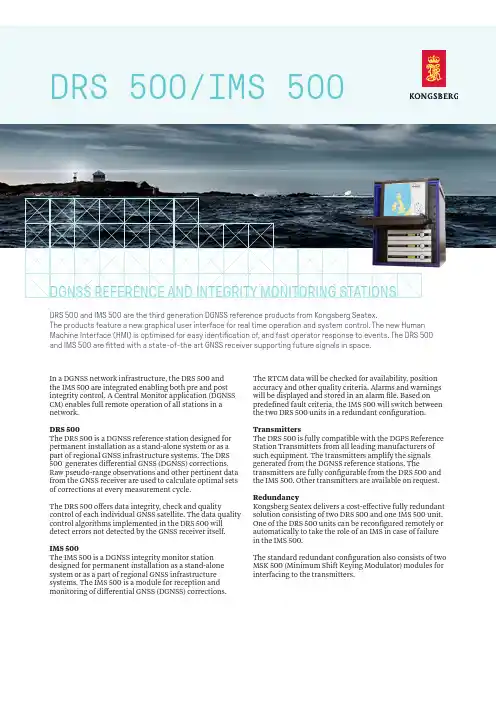
DRS 500/IMS 500In a DGNSS network infrastructure, the DRS 500 andthe IMS 500 are integrated enabling both pre and post integrity control. A Central Monitor application (DGNSS CM) enables full remote operation of all stations in a network.DRS 500The DRS 500 is a DGNSS reference station designed for permanent installation as a stand-alone system or as a part of regional GNSS infrastructure systems. The DRS 500 generates differential GNSS (DGNSS) corrections. Raw pseudo-range observations and other pertinent data from the GNSS receiver are used to calculate optimal sets of corrections at every measurement cycle.The DRS 500 offers data integrity, check and quality control of each individual GNSS satellite. The data quality control algorithms implemented in the DRS 500 will detect errors not detected by the GNSS receiver itself. IMS 500The IMS 500 is a DGNSS integrity monitor station designed for permanent installation as a stand-alone system or as a part of regional GNSS infrastructure systems. The IMS 500 is a module for reception and monitoring of differential GNSS (DGNSS) corrections. The RTCM data will be checked for availability, position accuracy and other quality criteria. Alarms and warnings will be displayed and stored in an alarm file. Based on predefined fault criteria, the IMS 500 will switch between the two DRS 500 units in a redundant configuration. TransmittersThe DRS 500 is fully compatible with the DGPS Reference Station Transmitters from all leading manufacturers of such equipment. The transmitters amplify the signals generated from the DGNSS reference stations. The transmitters are fully configurable from the DRS 500 and the IMS 500. Other transmitters are available on request. RedundancyKongsberg Seatex delivers a cost-effective fully redundant solution consisting of two DRS 500 and one IMS 500 unit. One of the DRS 500 units can be reconfigured remotely or automatically to take the role of an IMS in case of failure in the IMS 500.The standard redundant configuration also consists of two MSK 500 (Minimum Shift Keying Modulator) modules for interfacing to the transmitters.DGNSS REFERENCE AND INTEGRITY MONITORING STATIONSDRS 500 and IMS 500 are the third generation DGNSS reference products from Kongsberg Seatex.The products feature a new graphical user interface for real time operation and system control. The new Human Machine Interface (HMI) is optimised for easy identification of, and fast operator response to events. The DRS 500and IMS 500 are fitted with a state-of-the art GNSS receiver supporting future signals in space.TECHNICAL SPECIFICATIONS DRS 500/IMS 500GNSS RECEIVER CHANNEL CONFIGURATION240 channels1GPS L1, L2, L2C, L5GL ONASS L1,L2BeiDou2B1,B2Galileo E1, E5a, E5b, AltBOCSBASQZSSL-BandINTERFACESSerial data (default) 6 x RS-232/RS-4224 x Ethernet3 x USB 2.0Baud rate Up to 115 200 bytes/secConnection for keyboard and monitor.MEAN TIME BETWEEN FAILUREMTBF > 50.000 hoursWEIGHTS AND DIMENSIONSDRS/IMS Unitincluding strain relief 5.4 kg, 89 x 485 x 412 mmGNSS antenna 7.6 kg, 380 mm x 200 mm¹ Tracks up to 120 L1/L2 satellites² Firmware update required³Recommended +5 to +40POWER SPECIFICATIONSDRS/IMS Unit 110 to 240 V AC, max. 60 W GNSS antenna 5 V DC from processing unit ENVIRONMENTAL SPECIFICATIONSOperating temperature rangeDRS/IMS Unit -15 to + 55 °C3GNSS antenna -55 to +85 °CHumidityDRS/IMS Unit Max. 95 % non-condensingGNSS antenna Hermetically sealedMechanicalVibration IEC 60945/EN 60945 Electromagnetic compatibilityCompliance to EMCD,immunity/emission IEC 60945/EN 60945PRODUCT SAFETYLow voltage IEC 60950-1/EN 60950-1Specifications subject to change without any further noticeKONGSBERG SEATEXSwitchboard: +47 73 54 55 00Global support 24/7: +47 33 03 24 07E-mailsales:****************************.com E-mailsupport:******************************* /maritimeJanuary220 HMI based configuration including:larm threshold and observation interval settingsTCM and RSIM message schedulingNSS receiver parameter configuration and resetsroadcast integrity mode configuration。
FCPM-6000RCIntegrated Fr equency Co unter & Power MeterProduct OverviewMini-Circuits ’ FCPM-6000RC Integrated Frequency Counter & Power Meter is a compact (5.00 x 2.66 x 1.36”) precision test device controlled via USB or Ethernet (HTTP and Telnet protocols) or operated as standalone test instrument. It simplifies test setups by enabling synchronized frequency and power measurements from a single device. The unit features an LCD display allowing convenient readings directly off the measurement head, while our user-friendly GUI software enables easy remote test management via USB or Ethernet.Full software support is provided, including our user-friendly GUI application for Windows and a full API and programming instructions for both Windows and Linux environments (32-bit and 64-bit systems). The latest version of the full software package can be downloaded from https:///softwaredownload/fcpm.html at any time.USB / EthernetTrademarks: Windows is a registered trademark of Microsoft Corporation in the United States and other countries. Linux is a registered trademark of Linus Tor -valds. Mac is a registered trademark of Apple Corporation. Pentium is a registered trademark of Intel Corporation. Neither Mini-Circuits nor the Mini-Circuits FCPM-6000RC are affiliated with or endorsed by the owners of the above referenced trademarks Mini-Circuits and the Mini-Circuits logo are registered trademarks of Scientific Components Corporation.The Big Deal• Automatically synchronizedpower & frequency measurements • USB and Ethernet control• Includes GUI with measurement applications software, simplifying complex measurements • Measurement speed 30msCASE STYLE: JL202950Ω -30 dBm to +20 dBm, 1 MHz to 6000 MHzApplications• Production testing systems• Field testing & remote location monitoring • automatic, scheduled data collection• Evaluate high-power, multi-port devices with built-in virtual couplers/attenuators & other software tools.Included AccessoriesModel No.DescriptionB-RJ45-CBL-7+2.6 ft. USB cable1Software PackageRev. E ECO-019961EDR-11250Electrical Specifications (CW) 1, -30 dBm to +20 dBm, 1 to 6000 MHz2 Maximum continuous safe operational power limit: +23 dBm. Performance is guaranteed up to +20 dBm.3 The FCPM-6000RC can operate down to -32 dBm, however performance is guaranteed only in the range specified in the table.4 Minimum power for Frequency measurement at 190-240 MHz may degrade by up to 3 dB due to measurement band switching.5 When using Faster mode at high frequencies below -20dBm, use of averaging is recommended to prevent noise errors.6 When using Faster mode power reading below -20dBm, uncertainty value may increase by up to 0.2 dB relative to Low noise mode power reading.7 Accuracy shown using external 10 MHz reference synchronized to test signal. Using Internal Reference adds 2 ppm of tested frequency to the accuracy values shown.8 Software function set by user, default option 1000 mec.Permanent damage may occur if any of these limits are exceeded. Operating in the range between operating power limits and absolute maximum ratings for extended periods of time may result in reduced life and reliability.Reference Input(BNC-Female) Signal Input(N-Typ-Male) Power & Control (Push-Pull connector) ConnectionsTypical Performance Curves1.001.031.061.091.121.15100020003000400050006000V S W R (:1)Frequency (MHz)VSWR-4%-2%0%2%4%6%8%100020003000400050006000L i n e a r i t y (%)Frequency (MHz)Linearity @+25O C-0.4-0.3-0.2-0.10.00.10.20100020003000400050006000U U n c e r t a i n t y (d B )Frequency (MHz)Uncertainty of Power Measurement @ +25°C-42-39-36-33-30-270100020003000400050006000P o w e r I n (d B m )Frequency (MHz)Typ. Input Power Threshhold for FrequencyMeasurement @ +25°C-500-300-1001003005000100020003000400050006000U n c e r t a i n t y (H z )Frequency (MHz)Uncertainty of Frequency Measurement @ +25°COutline Drawing (JL2029)inchFCPM-6000RC to be used with the supplied control cable only.Connection diagramsConnection diagram for USB control Note:splitter not supplied by Mini-Circuits Connection diagram for Ethernet control, using PoE systemConnection diagram for Ethernet control, using power adapterGraphical User Interface (GUI) for Windows Key Features:• Automatically synchronized power and frequency measurements.• Relative and Average power measurements• Setting measurement speed for power and frequency independantly.• Freq. & Power measurment data recording • Measurement application tools• online graphical display of power measurement • USB, HTTP or Telnet control of FCPM• Setting Ethernet configurationSoftware & Documentation Download:• Mini-Circuits’ full software and support package including user guide, Windows GUI, DLL files, programming manual and examples can be downloaded free of charge from https:///softwaredownload/fcpm.html .• Please contact ****************************** for supportApplication Programming Interface (API)Windows Support:• API DLL files exposing the full power sensor functionality • ActiveX COM DLL file for creation of 32-bit programs • .Net library DLL file for creation of 32 / 64-bit programs• HTTP Get/Post and Telnet protocols use SCPI commands to provide full control.• Supported by most common programming environments (refer to application note AN-49-001 for summary of tested environments)Linux Support:• Full power sensor control in a Linux environment is achieved by way of USB interrupt commands.ModelDescriptionFCPM-6000RCIntegrated Frequency Counter & Power MeterOrdering Information Additional NotesA. Performance and quality attributes and conditions not expressly stated in this specification document are intended to be excluded and do not form a part of this specification document.B. Electrical specifications and performance data contained in this specification document are based on Mini-Circuit’s applicable established test performance criteria and measurement instructions.C. The parts covered by this specification document are subject to Mini-Circuits standard limited warranty and terms and conditions (collectively, “Standard Terms”); Purchasers of this part are entitled to the rights and benefits contained therein. For a full statement of the Standard Terms and the exclusive rights and remedies thereunder, please visit Mini-Circuits’ website at /MCLStore/terms.jspCalibrationDescriptionCAL-FCPM-6000RCCalibration ServiceClick HereIncluded Accessories Part No.DescriptionUSB-RJ45-CBL-7+6.6 ft (2 m) “Y” data cable with USB Type-A and RJ45 plug connectors 910 Power plugs for other countries are also available, if you need a power plug for a country not listed in the table please contact testsolutions@ for su pport.11 The USB-AC/DC-5 may be used to provide the 5VDC power input via USB port if operating with Ethernet control. Not required if using USB control.Optional AccessoriesDescriptionUSB-AC/DC-5AC/DC 5V DC Power Adapter with US, EU, IL, UK, AUS, and China power plugs 10,11USB-RJ45-CBL-7+ (spare) 6.6 ft (2 m) “Y” data cable with USB Type-A and RJ45 plug connectors NF-SM50+ N-Type Female to SMA Male Adapter (For mating with SMA devices).NF-SF50+N-Type Female to SMA Female Adapter NF-BM50+N-Type Female to BNC Male Adapter.9 FCPM-6000RC to be used with the supplied control cable only.。
GT2005 supersonic and transonic compressors:past,status and technology trends(Klaus D.Broichhausen,MTU Aero Engines GmbH)Transonic compressors with high leading edge Mach numbers are today state of the art in gas turbine design. This holds true for both aero engines and stationary gas turbines. In the early days of highly loaded compressors, the development started from the ideas about supersonic compressors with very high stage pressure ratios. This historical development and the basic ideas are described. The contributions of H. E. Gallus to this development are specially referred to. On that basis, today’s transonic compressors with reduced loading have been developed. The characteristic physics and design features of recent compressors are discussed with respect to aerodynamics, performance, structure mechanics and production technology. This is also done in view of the ideas of the pioneers in this field. Future technology trends of these compressor types as well as new compressor types are presented in the last part of the paper.INTRODUCTIONTwo basic factors determine the energy transfer to the fluid in axial flow compressors: The circumferential speed and the turning of the flow. Increasing the workload per compressorstage to the limits and reducing stage count and weight of the whole component have been driving factors in jet engine development already in the early years of the jet engine pioneers.With early axial flow compressors the factor “circumferential speed” was limited to subsonic or e ven nearly incompressible flow. Consequently, these compressors had very low stage pressure ratios. The blades and vanes generally had only a slight turning, high aspect ratios and low solidity. In the same time period first experiences were gained with transonic or supersonic external flows on airplanes and wings. These first systematic investigations on supersonic airfoil flow and the experiences with transonic and supersonic flight opened up a new option for the compressor designers: The idea of using high circumferential speeds and – as a consequence – high flow velocities up to supersonic speeds in axial flow compressors.NOMENCLATUREh 焓值LE 前缘M, Ma 马赫数n/n0 轴的实际转速/设计转速p/p t1 静压/总压TE 尾缘u 圆周速度z 轴向η 等熵效率(static/static)ηt 等熵效率(total/total)πt 总压比Subscripts1 转子进口2 转子出口R 转子REL 参考物的框架St 级FIRST EXPERIENCES WITH TRANSONIC AND SUPERSONIC FLOWS IN COMPRESSORSThe Pioneers of Supersonic Compressor FlowIn the forties of the last century the pioneers of high speed transonic and supersonic compressors started with a big step: They did not opt for an evolutionary increase of the circumferential speed on the basis of subsonic axial flow compressors, and thus for creating transonic compressors with supersonic flow near the rotor blade tip. Instead, they tried to design compressors for supersonic flowfrom hub to tip, hoping to materialize the pressure rise by means of gas dynamic compression shocks.With their revolutionary designs the first phase of supersonic and transonic compressor development began.This development started in parallel in the USA and in Germany. Weise’s [1] first supersonic compressor had moderate circumferential speed, and consequently a subsonic rotor flow. His design intend was to generate supersonic absolute flow at the exit of the rotor. In the following stator a strong shock with subsonic downstream Mach number should be stabilized by increasing the back pressure (Fig. 1(a)). Due to the low rotor speed the total pressure ratio was only in the order of 1.35. Compared to the pressure ratios achieved in those days, however, even this moderate pressure ratio was a big step. Absolutely disappointing was the efficiency: Due to a shock-induced separation in the stator it was as low as 26 %.These basic investigations were continued in the USA. The compressors of Kantrowitz [2] and Klapproth et al. [3] both featured high rotational speeds and supersonic rotor flow (Fig.1(b), 1(c)). They differed with respect to the distribution of pressure rise and turning. The Kantrowitz compressor had a supersonic rotor and a subsonic stator with high turning. In the rotor a shock was stabilized by increased back pressure – it was the first “shock-in-type rotor”. The pressure rise in the rotor was achieved only by the shock and the turning in the rotor was extremely low. The high turning in the stator was realized – for the first time in a supersonic compressor – by a tandem vane. In1952 Klapproth presented a rotor with supersonic relative inlet flow and high turning. The exit flow of the rotor was also supersonic for both, the relative and the absolute system – the first “impulse-type rotor” was created. Klapproth intended to decelerate the supersonic absolute flow (with a Mach number of about 2) in a single-row stator and a single strong shock, stabilized by back pressure. In these designs and experiments the first steps towards highly loaded compressors with supersonic flow had been made. Extremely high total pressure ratios had been achieved. The rotor efficiencies for both prototypes were very promising. And even the stage efficiencies constituted a significant progress in comparison to the first experiments of Weise.New Designs and Progress of the Second GenerationThe results and the experience of these pioneers in supersonic compressor research have proved that the idea of achieving higher pressure ratios by higher circumferential speed and increased flow velocities in supersonic and transonic compressors could be turned into reality. This idea was resumed in the sixties and seventies for two reasons:First, the jet engines of these days showed increasing demand for higher thrust to weight ratios. This resulted in increased aerodynamic loading of the turbo-components and the trend towards fewer stages in the compressors.The second reason was the option of applying highly loaded compressors with reduced stage numbers in small gas turbines. These small engines were intended as driving motors for large automotive vehicles, as separate engines used in airplanes with vertical take off and landing capabilities and as jet engines for UAV applications.This general trend towards fewer stages and higher stage pressure ratios resulted in two different development lines which ultimately interacted very fruitfully. These two different types are the supersonic compressor with supersonic flow in at least one axial plane like the compressors of Weise, Kantrowitz and Klapproth and – with lower loading and lower flow velocities – the transonic compressor.Supersonic CompressorsIn the first development line the investigations of supersonic compressors were restarted in Europe at the VKI by Breugelmans [4] and at the Institute of Jet Propulsion and Turbomachinery of RWTH Aachen by Dettmering and Gallus and their teams [5, 6]. Especially Gallus has the merit of having enabled a continuous research on supersonic compressors for about 30 years. In the USA a parallel development was started again at the Wright Patterson Air Force Base and strongly promoted by Wennerstrom resulting in several high performance compressors, for example [7].The engineers at RWTH Aachen started applying the experience of Oswatitsch in the field of supersonic diffusers to plane compressor cascades for stator vanes, and studying systematically the general design parameters of supersonic compressors. These cascade tests (Fig. 2, Becker [8]) indicated that supersonic inlet flow and high turning can be managed by two blade rows interfering axially (tandem cascade). The goal was to decelerate a supersonic inlet flow with a Mach number of about 1.4 in combination with a high turning of 45 degrees to low subsonic speeds in the exit of the cascade. It could be shown that a combination of a turning blade row and a second diamond shaped blade row, which is overlapping and avoiding suction side separation of the first row, is an optimum arrangement for both supersonic and subsonic (i.e. throttled) flow. Figure 2 shows the cascade with fully supersonic flow. In case of maximum back pressure a strong shock is stabilized in the entrance region generating subsonic flow in the passage.The following investigations of the supersonic compressor itself were focused basically on two types of supersonic rotors already known from the early pioneers:The impulse-type rotor combined relative supersonic flow in the inlet, in the blade passage and at the rotor exit with high turning. Having an extremely high total pressure increase (~3.5), the resulting static pressure increase of this type of rotors was small or even negative (impulse-type). The absolute exit Mach number – and in some cases even the axial component – was supersonic.In the shock-in-type rotor the relative inlet flow of the rotor was also supersonic. This supersonic flow was decelerated to subsonic flow in the blade passage by a strong shock. So the flow pattern was similar to today’s transonic rotors at maximum back pressure. The shock itself was stabilized by backpressure or by the geometry of the rotor passage. In the latter case, the rotor flow corresponded to theflow in a choked or spilled diffuser: Supersonic inlet flow, deceleration to subsonic Mach numbers due to the shock and acceleration to a sonic relative Mach number at the exit of the rotor.Both rotors have been designed and tested successfully at the Institute of Jet Propulsion and Turbomachinery of RWTH Aachen. A documentation of these tests is given by Simon [9] and Gallus et al. [10]. The experimental investigation of a shock-in-type rotor with a passage shock stabilized only by the passage exit cross section is described by Broichhausen and Gallus [11].Summarizing these tests and also looking to the results of the other research groups (e.g. Wilcox [12], Ritter and Johnsen [13] and Breugelmans [14, 15]) the benchmark total isentropic efficiency of the impulse-type rotors was around 90 %, of the shock-in-type rotors in the order of 87 % with total pressure ratios higher than 3. The work at Wright Patterson Air Force Base on supersonic and transonic rotors led to tandem rotors with "splitter vanes" (Wennerstrom [7]). These designs experimentally proved to have an extremely good performance in terms of both efficiency and off-design behavior. Here also efficiencies in the order of 87 % and total pressure ratio of 3.5 have been achieved.Having satisfying rotors of different designs, the downstream stators had to decelerate the supersonic inlet flow to moderate subsonic Mach numbers and to turn it into axial direction.For that purpose the team at the RWTH Aachen used tandem stators based on their cascade results. In spite of the encouraging plane cascade results, this extreme stator loading turned out to be a challenge in nearly all investigations downstream of a supersonic rotor.For the combination of a shock-in-type rotor and a tandem stator, however, a good stage performance could be proved experimentally. This can be seen from the axial distribution ofstatic pressure at the casing (Fig. 3, Gallus et al. [16]). It can be recognized that the back pressure increase results in a throttling of the stator up to a point where a strong shock is stabilized inthe entrance region of the stator and the whole channel flow is subsonic. The rotor itself is not influenced by the back pressure increase (“unique incidence effect” in supersonic cascade flows (Lichtfuß and Starken [17])) and its operation remains very stable. In this demonstrator a total pressure ratio of 3 was achieved in combination with a total isentropic stage efficiency in the order of 75 %. The rotors with totally supersonic flow in the blade passage (impulse-type) showed a deficit in stage environment. Having superior efficiencies when operated alone with no downstream stator, they were already slightly throttled by a following stator in spite of supersonic axial flow in the rotor exit. Thereason for that upstream influence of the stators turned out to be an unsteady interference between stator and rotor. The reduced flow velocities in the wakes of the supersonic rotor caused a subsonic axial flow component, which enabled an upstream impact of the following stator. This effect could only be avoided using a variable stator, developed and designed at the DLR (Lichtfuß and Starken [18]) and enabling a higher supersonic axial Mach number between rotor exit and stator inlet. In this case, a back pressure increase up to the design point of the stator turned out to be critical due to shock induced stator vibrations.Because of the encouraging performance data of the supersonic axial compressor withshock-in-type rotor and tandem stator, this type of compressor was used as the basis for the development and a series of experimental investigations of supersonic diagonal compressor stages (Fig.4, Mönig et al. [19, 20], Elmendorf et al. [21, 22] and Kurz [23]). A possible application of this compressor type was planned to be a small UAV jet engine. The diagonal rotor proved to have efficiencies slightly lower than those of purely axial supersonic compressors with a total pressure ratio higher than 6. At the end (Kurz [23]) the diagonal compressor stage with optimized tandem stator reached pressure ratios of about 4.8 with total isentropic efficiencies in the order of 74 %, working absolutely stable for the whole speed range. Taking into account a mean channel height in the stator of only 13 mm (which was necessary because of test bed limitations), these results looked promising. Unfortunately, however, the investigations have been stopped due to restrictions concerning the freon test gas with respect to environment.All these results about turning and decelerating supersonic flows in compressors, about managing shocks and shock boundary layer interaction as well as the knowledge of the off design performance of highly loaded supersonic stages (Broichhausen [24]) have had a strong influence on the second development line mentioned above, the transonic compressors. Transonic CompressorsTransonic compressors are the second development line, being influenced strongly by the findings of the supersonic compressor pioneers. This development was done quite parallel to the investigations of supersonic compressors described above. Researchers at different locations intended to increase the compressor loading in the “evolutionary way”. Coming from subsoniccompressors and adopting the experience of supersonic flow compressors as well as the knowledge about transonic flows around wings, they investigated transonic compressors with relative inlet flow velocities near or higher than that of sound upstream at the rotor tip. The relative inlet flow in the blade root section in most cases was subsonic. Because of the high turning even in these sections supersonic flow fields occurred within the rotor passage at the suction sides of the blades. In the field of transonic compressors –amongst others –important contributions were made at MIT, DLR, DRA and NASA (e.g. Thompkins [25], Epstein [26], Weyer and Dunker [27], Calvert and Stapleton [28] and Strazisar [29]). A strong leverage for the new developments and designs was also the progress made in computational methods and optical measurement techniques leading to a deeper understanding of the loss mechanisms of supersonic relative flow in compressors and the modeling of these losses (e.g. König et al. [30] and Puterbaugh et al. [31]). All these groups and a lot of other engineers in research and industry have been extremely successful so that transonic compressors could be used in jet engines very soon and are today a standard part of jet engines and stationary gas turbines.Depending on the upstream Mach number of transonic compressors, two different types can be distinguished according to the aerodynamics and the corresponding profile geometries.These two different types of profiles can also be found radially distributed from hub to tip of a single rotor according to the relative inlet Mach number. A summary of the basicperformance of these profiles is given in Bölcs and Suter [32] and Cumpsty [33].Coming from the classical NACA profiles special “supercritical”profiles have been developed for subsonic inlet Mach numbers and a local transonic pocket inside of the passage caused by the suction side acceleration. The early profiles of that class had a “roof top” likepressure distribution according to the profiles of transonic airplane wings. In cascade tests these profiles proved to be able to combine high turning with very low losses even at high subsonic Mach numbers. However, for application in a compressor the tolerance against varying incidence was too low. This deficit was compensated by highly efficient profiles with a peaky pressure distribution for design incidence. Accordingly, at maximum incidence a kind of a roof top like pressure distribution was generated.For slightly higher inlet Mach numbers around speed of sound modern profiles with custom tailored curvature have been developed based on the classical double circular arc profiles. Their main design goal is to reduce the pre-shock Mach number and combine that with maximum turning. As a result, the curvature in the supersonic part is reduced the more, the higher the inlet Mach number is. Profiles with elliptical leading edges, reduced curvature at the front end and a low overall turning showed the best flow and loss characteristics.As a consequence, for further increased Mach numbers (in the order of 1.3 and higher) the most important design intent is to reduce the Mach number in front of the passage shock. This is of primary importance due to the strongly rising pressure losses with increasing pre-shock Mach number, and because of the increasing pressure losses due to the shock boundary layer interaction or shock induced separation. This reduction of the pre-shock Mach number can be achieved by zero or even negative curvature in the front end of the blade suction side and a resulting pre-compression shock-wave system reducing the Mach number upstream of the final strong passage shock. The same effect can also be generated by a radial contraction of the flow channel (hub to tip surface). This is the reason, why even flat looking blades can generate –in three dimensions – a flow pattern with a pre-compression shock system in front of the blade passage shock.The low pressure and high pressure compressors of the EJ200 engine are shown in Fig. 5 as examples for highly loaded, high performance transonic rotors of an aero engine.FROM RESEARCH TO APPLICATION: STATUS AND TRENDS OF TRANSONIC COMPRESSORSCharacteristic Parameters of Transonic CompressorsA closer look at the development of some characteristic parameters for axial flow transonic compressors, being installed in today’s jet engines, shows that the aerodynamic development since the basic applications is again a continuous one: To maintain high efficiencies, the relative flow tip Mach numbers of the rotors as well as the absolute inlet Mach numbers in the root section of the stators are limited. A typical value for the rotor inlet flow at the tip is Ma ~ 1.3 (Fig. 6(a)). So, the continuous progress of aerodynamics has been focused to the increase of efficiencies and pressure ratios and to the improvement of the off-design behavior at roughly the same level of inlet Mach numbers. The resulting high stage pressure ratios (Fig. 6(c)) in the first stages of today’s high efficiency transonic compressors in the order of 1.7-1.8 are realized by combining high rotor speeds (tip speed in the order of 500 m/sec) and high stage loading (2Δh/u² in the order of 1.0, Fig. 6(d)).------------------------------Another--Paragraph----------------------------------------------------------------------------The benefit is a considerable reduction of length and weight of the compressor. Concerning the flow physics, the basic idea is – as already investigated in the early experiments on supersonictandem cascades (Dettmering et al. [5]): The two mechanisms of flow deceleration are split up and distributed to two different blade rows (Fig. 14, right hand side). The first blade row produces the pressure rise exclusively by a shock. The necessary turning behind the shock, which is problematical in standard transonic rotors, is then done in the second row with fresh boundary layers.Supersonic flow over the whole span and a strong shock stabilized by back pressure is tested in another new design by Lawlor et al. [44], (Fig. 15). Here, the design principles of a supersonic aero engine intake with a multi-shock compression system and a boundary layer treatment (suction and injection) are transferred to a compressor rotor. The rotor has only threeor four “blades” without curvature. These blades form the passage, where the multi-shock system is stabilized in combination with a pronounced ramp generated by contouring the hub. In a first experiment the rotor worked very satisfying. With the achieved extreme pressure ratio in combination with moderate exit Mach numbers, the range of application goes from a replacement of screw compressors to turbochargers and gas turbine engines.SUMMARYThe history of supersonic flow in compressors dates from the forties of the last century. The pioneers in this field started with a big step, designing real supersonic compressors. Thevery successful further development of this compressor type was continued roughly until the end of the century, but was then more or less abandoned, as a parallel development line –the transonic compressors – achieved significantly higher efficiencies.They are state of the art in the compression systems of today’s aero engines and stationary gas turbines. The challenges of supersonic compressors have contributed to a great extent to their success story, as the fundamental flow physics could be transferred to transonic axial flow compressors. In the future there will be still options for further radical improvementslike highly effective surge control systems or even for completely new working principles based again on supersonic flow.列板壁压气机匝道亚音速扩压器。
1INTRODUCTION1.1FEATURES1.2APPLICATIONS1.3DESCRIPTION•Battery Fuel Gauge for 1-Series Li-Ion •Smartphones Applications•PDAs•Resides on System Main Board•Digital Still and Video Cameras –Works With Embedded or Removable •Handheld TerminalsBattery Packs •MP3or Multimedia Players•Two Varieties–bq27500:Uses PACK+,PACK–,and T Battery Terminals–bq27501:Works With Battery ID Resistor in Battery PackThe Texas Instruments bq27500/01system-side Li-Ion battery fuel gauge is a microcontroller •Microcontroller Peripheral Provides:peripheral that provides fuel gauging for single-cell –Accurate Battery Fuel GaugingLi-Ion battery packs.The device requires little system –Internal Temperature Sensor for System microcontroller firmware development.The Temperature Reportingbq27500/01resides on the system main board,and –Battery Low Interrupt Warning manages an embedded battery (non-removable)or a –Battery Insertion Indicator removable battery pack.–Battery ID Detection–96Bytes of Non-Volatile Scratch-Pad The bq27500/01uses the patented Impedance FLASHTrack™algorithm for fuel gauging,and provides information such as remaining battery capacity •Battery Fuel Gauge Based on Patented (mAh),state-of-charge (%),run-time to empty (min.),Impedance Track™Technologybattery voltage (mV),and temperature (°C).–Models the Battery Discharge Curve for Accurate Time-to-Empty Predictions Battery fuel gauging with the bq27500requires only –Automatically Adjusts for Battery Aging,PACK+(P+),PACK–(P–),and Thermistor (T)Battery Self-Discharge,andconnections to a removable battery pack or Temperature/Rate Inefficienciesembedded battery.The bq27501works with –Low-Value Sense Resistor (10m Ωor Less)identification resistors in battery packs to gauge •I 2C™Interface for Connection to System batteries of different fundamental chemistries and/or Microcontroller Portsignificantly different rated capacities.•12-Pin 2,5-mm ×4-mm SON PackageTYPICAL APPLICATIONPlease be aware that an important notice concerning availability,standard warranty,and use in critical applications of Texas Instruments semiconductor products and disclaimers thereto appears at the end of this document.Impedance Track is a trademark of Texas Instruments.I 2C is a trademark of Philips Electronics.PRODUCTION DATA information is current as of publication date.Copyright ©2007–2008,Texas Instruments IncorporatedProducts conform to specifications per the terms of the Texas Instruments standard warranty.Production processing does not necessarily include testing of all parameters.Contents1INTRODUCTION..........................................4.1DATA COMMANDS..................................1.1FEATURES........................................... 4.2DATA FLASH INTERFACE.........................1.2APPLICATIONS...................................... 4.3MANUFACTURER INFORMATION BLOCKS......1.3DESCRIPTION....................................... 4.4ACCESS MODES...................................2DEVICE INFORMATION.................................4.5SEALING/UNSEALING DATA FLASH..............2.1AVAILABLE OPTIONS............................... 4.6DATA FLASH SUMMARY...........................2.2PIN DIAGRAMS......................................5FUNCTIONAL DESCRIPTION........................2.3TERMINAL FUNCTIONS............................. 5.1FUEL GAUGING....................................3ELECTRICAL SPECIFICATIONS......................5.2IMPEDANCE TRACK™VARIABLES...............3.1ABSOLUTE MAXIMUM RATINGS................... 5.3DETAILED DESCRIPTION OF DEDICATED PINS.3.2RECOMMENDED OPERATING CONDITIONS...... 5.4TEMPERATURE MEASUREMENT.................3.3DISSIPATION RATINGS............................. 5.5OVERTEMPERATURE INDICATION...............5.6CHARGING AND CHARGE-TERMINATION3.4POWER-ON RESET..................................INDICATION.........................................3.5INTERNAL TEMPERATURE SENSORCHARACTERISTICS................................. 5.7POWER MODES....................................3.6HIGH-FREQUENCY OSCILLATOR.................. 5.8POWER CONTROL.................................3.7LOW-FREQUENCY OSCILLATOR.................. 5.9AUTOCALIBRATION................................3.8INTEGRATING ADC(COULOMB COUNTER)6APPLICATION-SPECIFIC INFORMATION..........CHARACTERISTICS.................................6.1BATTERY PROFILE STORAGE AND SELECTION3.9ADC(TEMPERATURE AND CELL6.2APPLICATION-SPECIFIC FLOW AND CONTROL.MEASUREMENT)CHARACTERISTICS.............7COMMUNICATIONS3.10DATA FLASH MEMORY CHARACTERISTICS...................................................................3.11I2C-COMPATIBLE INTERFACE COMMUNICATION7.1I2C INTERFACE.....................................TIMING CHARACTERISTICS........................8REFERENCE SCHEMATICS..........................4GENERAL DESCRIPTION..............................8.1SCHEMATIC........................................2Contents Submit Documentation Feedback2DEVICE INFORMATION2.1AVAILABLE OPTIONS2.2PIN DIAGRAMSBAT V SSSRN SRPV CC BAT_GD SDA SCLBAT_LOW TSBI/TOUTBAT V SSV CC BAT_LOW TS BI/TOUTNCSRN SRPBAT_GD SDA SCLRID 2.3TERMINAL FUNCTIONSTAPE and FIRMWARE COMMUNICATIONPART NUMBER PACKAGE (2)T AREEL VERSION (1)FORMATQUANTITY bq27500DRZR 3000V1.06bq27500DRZT 250bq27500DRZR-V100300012-pin,2,5-mm ×4-mmV1.08–40°C to 85°CI 2CSONbq27500DRZT-V100250bq27501DRZR 3000V1.08bq27501DRZT250(1)Ordering the device with the latest firmware version is recommended.To check the fiirmware revision and Errata list see SLUZ015(2)For the most current package and ordering information,see the Package Option Addendum at the end of this document,or see the TI website at .TERMINALTYPE (1)DESCRIPTIONbq27500bq27501NAME PIN NO.PIN NO.BAT 44I Cell-voltage measurement input.ADC inputBattery-good indicator.Active-low by default,though polarity can be configured through BAT_GD 1212O the [BATG_POL]of Operation Configuration .Open-drain outputBattery-low output indicator.Active-high by default,though polarity can be configured BAT_LOW 11O through the [BATL_POL]in Operation Configuration .Push-pull outputBattery-insertion detection input.Power pin for pack thermistor network.ThermistorBI/TOUT 22I/O multiplexer control pin.Open-drain I/e with pullup resistor >1M Ω(1.8M Ωtypical).NC 9––No connection (bq27500)RID –9I Resistor ID input (bq27501).Analog input with current sourcing capabilitiesSlave I 2C serial communications clock input line for communication with system (master).SCL 1111I Open-drain I/e with 10-k Ωpullup resistor (typical).Slave I 2C serial communications data line for communication with system (master).SDA 1010I/O Open-drain I/e with 10-k Ωpullup resistor (typical).Analog input pin connected to the internal coulomb counter where SRN is nearest the SRN 88IA System V SS connection.Connect to 5-m Ωto 20-m Ωsense resistor.Analog input pin connected to the internal coulomb counter,where SRP is nearest the SRP 77IA PACK–connection.Connect to 5-m Ωto 20-m Ωsense resistor.TS 33IA Pack thermistor voltage sense (use 103AT-type thermistor).ADC input V CC 55P Processor power input.Decouple with 0.1-µF capacitor,minimum.Device ground.Electrically connected to the IC exposed thermal pad (do not use thermal V SS 66Ppad as primary ground.Connect thermal pad to Vss via a PCB trace).(1)I =Digital input,O =Digital output,I/O =Digital input/output,IA =Analog input,P =Power connectionSubmit Documentation Feedback DEVICE INFORMATION 33ELECTRICAL SPECIFICATIONS3.1ABSOLUTE MAXIMUM RATINGS3.2RECOMMENDED OPERATING CONDITIONSover operating free-air temperature range (unless otherwise noted)(1)PARAMETERVALUE UNIT V CC Supply voltage range–0.3to 2.75V V IOD Open-drain I/O pins (BI/TOUT,SDA,SDL,BAT_GD)–0.3to 6VV BAT BAT input pin–0.3to 6V I Input voltage range to all other pins (TS,SRP,SRN,RID [bq27501only],NC –0.3to V CC +0.3V [bq27500only])Human-body model (HBM),BAT pin 1.5ESD kV Human-body model (HBM),all other pins 2T A Operating free-air temperature range –40to 85°C T F Functional temperature range –40to 100°C T stg Storage temperature range–65to 150°C(1)Stresses beyond those listed under "absolute maximum ratings"may cause permanent damage to the device.These are stress ratings only,and functional operation of the device at these or any other conditions beyond those indicated under "recommended operating conditions"is not implied.Exposure to absolute-maximum-rated conditions for extended periods may affect device reliability.T A =25°C,V CC =2.5V (unless otherwise noted)PARAMETERTEST CONDITIONSMIN TYP MAX UNIT V CC Supply voltage2.42.5 2.6V Fuel gauge in NORMAL mode.I CC Normal operating-mode current 100µA I LOAD >Sleep Current Fuel gauge in SLEEP mode.I SLP Low-power storage-mode current 15µA I LOAD <Sleep CurrentFuel gauge in HIBERNATE mode.I HIB Hibernate operating-mode current 1µA I LOAD <Hibernate Current V OL Output voltage,low (SDA,BAT_LOW,I OL =0.5mA 0.4V BI/TOUT)V OH(PP)Output voltage,high (BAT_LOW)I OH =–1mAV CC –0.5V External pullup resistor connected to V OH(OD)Output voltage,high (SDA,SCL,BI/TOUT)V CC –0.5VV CCInput voltage,low (SDA,SCL)–0.30.6V IL Input voltage,low (BI/TOUT)BAT INSERT CHECK MODE active –0.30.6VInput voltage,high (SDA,SCL) 1.26V IH(OD)Input voltage,high (BI/TOUT)BAT INSERT CHECK MODE active1.26C IN Input capacitance (SDA,SCL,BI/TOUT)35pF V A1Input voltage range (TS,RID [bq27501only])V SS –0.1252V V A2Input voltage range (BAT)V SS –0.1255V V A3Input voltage range (SRP,SRN)V SS –0.1250.125V t PUCDPower-up communication delay250ms ELECTRICAL SPECIFICATIONS 4Submit Documentation Feedback3.3DISSIPATION RATINGS3.4POWER-ON RESET3.5INTERNAL TEMPERATURE SENSOR CHARACTERISTICS3.6HIGH-FREQUENCY OSCILLATOR3.7LOW-FREQUENCY OSCILLATORT A ≤40°C DERATING FACTORPACKAGE R θJA POWER RATINGT A >40°C12-pin DRZ (1)482mW5.67mW/°C176°C/W(1)This data is based on using a four-layer JEDEC high-K board with the exposed die pad connected to a Cu pad on the board.The board pad is connected to the ground plane by a 2-×2-via matrix.T A =–40°C to 85°C,typical values at T A =25°C and V BAT =3.6V (unless otherwise noted)PARAMETERTEST CONDITIONSMIN TYP MAX UNIT V IT+Positive-going battery voltage input at V CC 2.09 2.2 2.31V V HYSHysteresis voltage45115185mVT A =–40°C to 85°C,2.4V <V CC <2.6V;typical values at T A =25°C and V CC =2.5V (unless otherwise noted)PARAMETERTEST CONDITIONSMINTYP MAXUNIT G TEMPTemperature sensor voltage gain–2mV/°CT A =–40°C to 85°C,2.4V <V CC <2.6V;typical values at T A =25°C and V CC =2.5V (unless otherwise noted)PARAMETERTEST CONDITIONSMINTYP MAXUNIT f OSC Operating frequency 2.097MHzT A =0°C to 60°C–2%0.38%2%f EIO Frequency error (1)(2)T A =–20°C to 70°C –3%0.38%3%T A =–40°C to 85°C–4.5%0.38%4.5%t SXO Start-up time (3)2.55ms(1)The frequency error is measured from 2.097MHz.(2)The frequency drift is included and measured from the trimmed frequency at V CC =2.5V,T A =25°C.(3)The start-up time is defined as the time it takes for the oscillator output frequency to be within ±3%of typical oscillator frequency.T A =–40°C to 85°C,2.4V <V CC <2.6V;typical values at T A =25°C and V CC =2.5V (unless otherwise noted)PARAMETERTEST CONDITIONSMIN TYP MAXUNIT f LOSC Operating frequency 32.768kHzT A =0°C to 60°C–1.5%0.25% 1.5%f LEIO Frequency error (1)(2)T A =–20°C to 70°C –2.5%0.25% 2.5%T A =–40°C to 85°C–4%0.25%4%t LSXO Start-up time(3)500µs(1)The frequency drift is included and measured from the trimmed frequency at V CC =2.5V,T A =25°C.(2)The frequency error is measured from 32.768kHz.(3)The start-up time is defined as the time it takes for the oscillator output frequency to be within ±3%of typical oscillator frequency.Submit Documentation Feedback ELECTRICAL SPECIFICATIONS 53.8INTEGRATING ADC (COULOMB COUNTER)CHARACTERISTICS3.9ADC (TEMPERATURE AND CELL MEASUREMENT)CHARACTERISTICS3.10DATA FLASH MEMORY CHARACTERISTICS3.11I 2C-COMPATIBLE INTERFACE COMMUNICATION TIMING CHARACTERISTICST A =–40°C to 85°C,2.4V <V CC <2.6V;typical values at T A =25°C and V CC =2.5V (unless otherwise noted)PARAMETERTEST CONDITIONSMIN TYPMAX UNIT V SR Input voltage range (V SR =V (SRN)–V (SRP))–0.1250.125V t SR_CONV Conversion time Single conversion1s Resolution 1415bits V SR_OS Input offset10µV INL Integral nonlinearity error ±0.007±0.034%FSR Z SR_IN Effective input resistance (1)2.5M ΩI SR_LKG Input leakage current(1)0.3µA(1)Specified by design.Not tested in production.T A =–40°C to 85°C,2.4V <V CC <2.6V;typical values at T A =25°C and V CC =2.5V (unless otherwise noted)PARAMETERTEST CONDITIONSMIN TYPMAXUNIT V ADC_IN Input voltage range –0.21V t ADC_CONV Conversion time 125ms Resolution 1415bits V ADC_OS Input offset1mV Effective input resistance (TS,RID Z ADC18M Ω[bq27501only])(1)bq27500/1not measuring cell voltage 8M ΩZ ADC2Effective input resistance (BAT)(1)bq27500/1measuging cell voltage100k ΩI ADC_LKG Input leakage current (1)0.3µA(1)Specified by design.Not tested in production.T A =–40°C to 85°C,2.4V <V CC <2.6V;typical values at T A =25°C and V CC =2.5V (unless otherwise noted)PARAMETERTEST CONDITIONSMIN TYPMAXUNIT t ONData retention (1)10Years Flash-programming write cycles (1)20,000Cycles t WORDPROG Word programming time (1)2ms I CCPROG Flash-write supply current (1)510mA(1)Specified by design.Not production testedT A =–40°C to 85°C,2.4V <V CC <2.6V;typical values at T A =25°C and V CC =2.5V (unless otherwise noted)PARAMETERTEST CONDITIONSMINTYPMAXUNIT t r SCL/SDA rise time 1µs t f SCL/SDA fall time 300ns t w(H)SCL pulse duration (high)4µs t w(L)SCL pulse duration (low) 4.7µs t su(STA)Setup for repeated start 4.7µs t d(STA)Start to first falling edge of SCL 4µs t su(DAT)Data setup time250nsELECTRICAL SPECIFICATIONS 6Submit Documentation FeedbackI2C-COMPATIBLE INTERFACE COMMUNICATION TIMING CHARACTERISTICS(continued)T A=–40°C to85°C,2.4V<V CC<2.6V;typical values at T A=25°C and V CC=2.5V(unless otherwise noted)PARAMETER TEST CONDITIONS MIN TYP MAX UNITReceive mode0t h(DAT)Data hold time nsTransmit mode300t su(STOP)Setup time for stop4µst(BUF)Bus free time between stop and start 4.7µsf SCL Clock frequency10100kHzt BUSERR Bus error time-out17.321.2sFigure3-1.I2C-Compatible Interface Timing DiagramsSubmit Documentation Feedback ELECTRICAL SPECIFICATIONS74GENERAL DESCRIPTIONThe bq27500/1accurately predicts the battery capacity and other operational characteristics of a single Li-based rechargeable cell.It can be interrogated by a system processor to provide cell information,such as state-of-charge(SOC),time-to-empty(TTE)and time-to-full(TTF).Information is accessed through a series of commands,called Standard Commands.Further capabilities are provided by the additional Extended Commands set.Both sets of commands,indicated by the general format Command(),are used to read and write information contained within the bq27500/1control and status registers,as well as its data flash mands are sent from system to gauge using the bq27500/1I2C serial communications engine,and can be executed during application development,pack manufacture,or end-equipment operation.Cell information is stored in the bq27500/1in non-volatile flash memory.Many of these data flash locations are accessible during application development.They cannot be accessed directly during end-equipment operation.Access to these locations is achieved by either use of the bq27500/1 companion evaluation software,through individual commands,or through a sequence of data-flash-access commands.To access a desired data flash location,the correct data flash subclass and offset must be known.The bq27500/1provides96bytes of user-programmable data flash memory,partitioned into three32-byte blocks:Manufacturer Info Block A,Manufacturer Info Block B,and Manufacturer Info Block C.This data space is accessed through a data flash interface.For specifics on accessing the data flash,see Section4.3,Manufacturer Information Blocks.The key to the high-accuracy fuel gauging prediction of the bq27500/1is Texas Instruments'proprietary Impedance Track™algorithm.This algorithm uses cell measurements,characteristics,and properties to create state-of-charge predictions that can achieve less than1%error across a wide variety of operating conditions and over the lifetime of the battery.The bq27500/1measures charge/discharge activity by monitoring the voltage across a small-value series sense resistor(5mΩto20mΩ,typ.)located between the system Vss and the battery PACK–terminal.When a cell is attached to the bq27500/1,cell impedance is computed,based on cell current,cell open-circuit voltage(OCV),and cell voltage under loading conditions.The bq27500/1must use an NTC thermistor Semitec103AT for temperature measurement,or can also be configured to use its internal temperature sensor.The bq27500/1uses temperature to monitor the battery-pack environment,which is used for fuel gauging and cell protection functionality.To minimize power consumption,the bq27500/1has several power modes:NORMAL,SLEEP, HIBERNATE,and BAT INSERT CHECK.The bq27500/1passes automatically between these modes, depending upon the occurrence of specific events,though a system processor can initiate some of these modes directly.More details can be found in Section5.7,Power Modes.NOTEFORMATTING CONVENTIONS IN THIS DOCUMENT:Commands:italics with parentheses and no breaking spaces,e.g.,RemainingCapacity().Data flash:italics,bold,and breaking spaces,e.g.,Design CapacityRegister bits and flags:brackets and italics,e.g.,[TDA]Data flash bits:brackets,italics and bold,e.g.,[LED1]Modes and states:ALL CAPITALS,e.g.,UNSEALED mode.8Submit Documentation Feedback GENERAL DESCRIPTION4.1DATA COMMANDS4.1.1STANDARD DATA COMMANDSThe bq27500/1uses a series of2-byte standard commands to enable system reading and writing of battery information.Each standard command has an associated command-code pair,as indicated in Table4-1.Because each command consists of two bytes of data,two consecutive I2C transmissions must be executed both to initiate the command function,and to read or write the corresponding two bytes of data.Additional options for transferring data,such as spooling,are described in Section7,I2C Interface.Standard commands are accessible in NORMAL operation.Read/write permissions depend on the active access mode,SEALED or UNSEALED(for details on the SEALED and UNSEALED states,see Section4.4,Access Modes).Table4-1.Standard CommandsNAME COMMAND CODE UNITS SEALED ACCESS UNSEALED ACCESS Control()CNTL0x00/0x01N/A R/W R/WAtRate()AR0x02/0x03mA R/W R/W AtRateTimeToEmpty()ARTTE0x04/0x05Minutes R R/W Temperature()TEMP0x06/0x070.1K R R/WVoltage()VOLT0x08/0x09mV R R/WFlags()FLAGS0x0a/0x0b N/A R R/W NominalAvailableCapacity()NAC0x0c/0x0d mAh R R/W FullAvailableCapacity()FAC0x0e/0x0f mAh R R/W RemainingCapacity()RM0x10/0x11mAh R R/W FullChargeCapacity()FCC0x12/0x13mAh R R/W AverageCurrent()AI0x14/0x15mA R R/W TimeToEmpty()TTE0x16/0x17Minutes R R/W TimeToFull()TTF0x18/0x19Minutes R R/W StandbyCurrent()SI0x1a/0x1b mA R R/W StandbyTimeToEmpty()STTE0x1c/0x1d Minutes R R/W MaxLoadCurrent()MLI0x1e/0x1f mA R R/W MaxLoadTimeToEmpty()MLTTE0x20/0x21Minutes R R/W AvailableEnergy()AE0x22/0x23mWh R R/W AveragePower()AP0x24/0x25mW R R/W TimeToEmptyAtConstantPower()TTECP0x26/0x27Minutes R R/WReserved RSVD0x28/0x29N/A R R/W CycleCount()CC0x2a/0x2b Counts R R/W StateOfCharge()SOC0x2c/0x2d%R R/WSubmit Documentation Feedback GENERAL DESCRIPTION94.1.1.1Control():0x00/0x01Issuing a Control()command requires a subsequent2-byte subcommand.These additional bytes specify the particular control function desired.The Control()command allows the system to control specific features of the bq27500/1during normal operation and additional features when the bq27500/1is in different access modes,as described in Table4-2.Table4-2.Control()SubcommandsCNTL SEALEDCNTL FUNCTION DESCRIPTIONDATA ACCESSCONTROL_STATUS0x0000Yes Reports the status of DF checksum,hibernate,IT,etc. DEVICE_TYPE0x0001Yes Reports the device type(eg:"bq27500")FW_VERSION0x0002Yes Reports the firmware version on the device typeHW_VERSION0x0003Yes Reports the hardware version of the device typeEnables a data flash checksum to be generated andDF_CHECKSUM0x0004Noreports on a readRESET_DATA0x0005Yes Returns reset dataReserved0x0006No Not to be usedPREV_MACWRITE0x0007Yes Returns previous MAC command codeReports the chemical identifier of the Impedance Track™CHEM_ID0x0008YesconfigurationBOARD_OFFSET0x0009No Forces the device to measure and store the board offset CC_INT_OFFSET0x000a No Forces the device to measure the internal CC offset WRITE_OFFSET0x000b No Forces the device to store the internal CC offsetSET_HIBERNATE0x0011Yes Forces CONTROL_STATUS[HIBERNATE]to1CLEAR_HIBERNATE0x0012Yes Forces CONTROL_STATUS[HIBERNATE]to0SEALED0x0020No Places the bq27500/1in SEALED access modeIT_ENABLE0x0021No Enables the Impedance Track™algorithmIF_CHECKSUM0x0022No Reports the instruction flash checksumCAL_MODE0x0040No Places the bq27500/1in calibration modeRESET0x0041No Forces a full reset of the bq27500/14.1.1.1.1CONTROL_STATUS:0x0000Instructs the fuel gauge to return status information to control addresses0x00/0x01.The status word includes the following information.Table4-3.CONTROL_STATUS Bit DefinitionsFlags()bit7bit6bit5bit4bit3bit2bit1bit0 High byte–FAS SS CSV CCA BCA––Low byte–HIBERNATE–SLEEP LDMD RUP_DIS VOK QENFAS=Status bit indicating the bq27500/1is in FULL ACCESS SEALED state.Active when set.SS=Status bit indicating the bq27500/1is in SEALED state.Active when set.CSV=Status bit indicating a valid data flash checksum has been generated.Active when set.CCA=Status bit indicating the bq27500/1coulomb counter calibration routine is active.Active when set.BCA=Status bit indicating the bq27500/1board calibration routine is active.Active when set.HIBERNATE=Status bit indicating a request for entry into HIBERNATE from SLEEP mode.True when set.Default is0.SLEEP=Status bit indicating the bq27500/1is in SLEEP mode.True when set.LDMD=Status bit indicating the bq27500/1Impedance Track™algorithm is using constant-power mode.True when set.Default is0 (constant-current mode).RUP_DIS=Status bit indicating the bq27500/1Ra table updates are disabled.Updates disabled when set.VOK=Status bit indicating the bq27500/1voltages are okay for Qmax.True when set.QEN=Status bit indicating the bq27500/1Qmax updates enabled.True when set.10Submit Documentation Feedback GENERAL DESCRIPTION4.1.1.1.2DEVICE_TYPE:0x0001Instructs the fuel gauge to return the device type to addresses0x00/0x01.4.1.1.1.3FW_VERSION:0x0002Instructs the fuel gauge to return the firmware version to addresses0x00/0x01.4.1.1.1.4HW_VERSION:0x0003Instructs the fuel gauge to return the hardware version to addresses0x00/0x01.4.1.1.1.5DF_CHECKSUM:0x0004Instructs the fuel gauge to compute the checksum of the data flash memory.Once the checksum has been calculated and stored,CONTROL_STATUS[CVS]is set.The checksum value is written and returned to addresses0x00/0x01(UNSEALED mode only).The checksum is not calculated in SEALED mode;however,the checksum value can still be read.4.1.1.1.6RESET_DATA:0x0005Instructs the fuel gauge to return the reset data to addresses0x00/0x01,with the low byte(0x00)being the number of full resets and the high byte(0x01)the number of partial resets.4.1.1.1.7PREV_MACWRITE:0x0007Instructs the fuel gauge to return the previous command written to addresses0x00/0x01.4.1.1.1.8CHEM_ID:0x0008Instructs the fuel gauge to return the chemical identifier for the Impedance Track™configuration to addresses0x00/0x01.4.1.1.1.9BOARD_OFFSET:0x0009Instructs the fuel gauge to compute the coulomb counter offset with internal short and then without internal short applied across the SR inputs.The difference between the two measurements is the board offset. After a delay of approximately32seconds,this offset value is returned to addresses0x00/0x01and written to data flash.The coulomb counter offset is also written to data flash.The CONROL STATUS [BCA]is also set.The user must prevent any charge or discharge current from flowing during the process. This function is only available when the fuel gauge is UNSEALED.When SEALED,this command only reads back the board-offset value stored in data flash.4.1.1.1.10CC_INT_OFFSET:0x000AInstructs the fuel gauge to compute the coulomb counter offset with internal short applied across the SR inputs.The offset value is returned to addresses0x00/0x01after a delay of approximately16seconds. This function is only available when the fuel gauge is UNSEALED.When SEALED,this command only reads back the CC_INT_OFFSET value stored in data flash.4.1.1.1.11WRITE_OFFSET:0x000BControl data of0x000b causes the fuel gauge to write the coulomb counter offset to data flash.4.1.1.1.12SET_HIBERNATE:0x0011Instructs the fuel gauge to force the CONTROL_STATUS[HIBERNATE]bit to1.This allows the gauge to enter the HIBERNATE power mode after the transition to SLEEP power state is detected.The [HIBERNATE]bit is automatically cleared upon exiting from HIBERNATE mode.4.1.1.1.13CLEAR_HIBERNATE:0x0012Instructs the fuel gauge to force the CONTROL_STATUS[HIBERNATE]bit to0.This prevents the gauge from entering the HIBERNATE power mode after the transition to the SLEEP power state is detected.It can also be used to force the gauge out of HIBERNATE mode.4.1.1.1.14SEALED:0x0020Instructs the fuel gauge to transition from the UNSEALED state to the SEALED state.The fuel gauge must always be set to the SEALED state for use in end equipment.4.1.1.1.15IT_ENABLE:0x0021This command forces the fuel gauge to begin the Impedance Track™algorithm,sets the active UpdateStatus n location to0x01and causes the[VOK]and[QEN]flags to be set in the CONTROL_STATUS register.[VOK]is cleared if the voltages are not suitable for a Qmax update.Once set,[QEN]cannot be cleared.This command is only available when the fuel gauge is UNSEALED.4.1.1.1.16IF_CHECKSUM:0x0022This command instructs the fuel gauge to compute the instruction flash checksum.In UNSEALED mode, the checksum value is returned to addresses0x00/0x01.The checksum is not calculated in SEALED mode;however,the checksum value can still be read.4.1.1.1.17CAL_MODE:0x0040This command instructs the fuel gauge to enter calibration mode.This command is only available when the fuel gauge is UNSEALED.4.1.1.1.18RESET:0x0041This command instructs the fuel gauge to perform a full reset.This command is only available when the fuel gauge is UNSEALED.4.1.1.2AtRate():0x02/0x03The AtRate()read-/write-word function is the first half of a two-function command set used to set the AtRate value used in calculations made by the AtRateTimeToEmpty()function.The AtRate()units are in mA.The AtRate()value is a signed integer,with negative values interpreted as a discharge current value.The AtRateTimeToEmpty()function returns the predicted operating time at the AtRate value of discharge.The default value for AtRate()is zero and forces AtRate()to return65,535.Both the AtRate()and AtRateTimeToEmpty()commands must only be used in NORMAL mode.4.1.1.3AtRateTimeToEmpty():0x04/0x05This read-word function returns an unsigned integer value of the predicted remaining operating time if the battery is discharged at the AtRate()value in minutes with a range of0to65,534.A value of65,535 indicates AtRate()=0.The fuel gauge updates AtRateTimeToEmpty()within1s after the system sets the AtRate()value.The fuel gauge automatically updates AtRateTimeToEmpty()based on the AtRate() value every1s.Both the AtRate()and AtRateTimeToEmpty()commands must only be used in NORMAL mode.4.1.1.4Temperature():0x06/0x07This read-word function returns an unsigned integer value of the temperature in units of0.1K measured by the fuel gauge and has a range of0to6,553.5K.4.1.1.5Voltage():0x08/0x09This read-word function returns an unsigned integer value of the measured cell-pack voltage in mV with a range of0to6,000mV.4.1.1.6Flags():0x0a/0x0bThis read-word function returns the contents of the fuel-gauge status register,depicting the current operating status.。
元器件交易网IMPORTANT NOTICETexas Instruments and its subsidiaries (TI) reserve the right to make changes to their products or to discontinueany product or service without notice, and advise customers to obtain the latest version of relevant informationto verify, before placing orders, that information being relied on is current and complete. All products are soldsubject to the terms and conditions of sale supplied at the time of order acknowledgement, including thosepertaining to warranty, patent infringement, and limitation of liability.TI warrants performance of its semiconductor products to the specifications applicable at the time of sale inaccordance with TI’s standard warranty. Testing and other quality control techniques are utilized to the extentTI deems necessary to support this warranty. Specific testing of all parameters of each device is not necessarilyperformed, except those mandated by government requirements.CERTAIN APPLICATIONS USING SEMICONDUCTOR PRODUCTS MAY INVOLVE POTENTIAL RISKS OFDEATH, PERSONAL INJURY, OR SEVERE PROPERTY OR ENVIRONMENTAL DAMAGE (“CRITICALAPPLICATIONS”). TI SEMICONDUCTOR PRODUCTS ARE NOT DESIGNED, AUTHORIZED, ORWARRANTED TO BE SUITABLE FOR USE IN LIFE-SUPPORT DEVICES OR SYSTEMS OR OTHERCRITICAL APPLICATIONS. INCLUSION OF TI PRODUCTS IN SUCH APPLICATIONS IS UNDERSTOOD TOBE FULLY AT THE CUSTOMER’S RISK.In order to minimize risks associated with the customer’s applications, adequate design and operatingsafeguards must be provided by the customer to minimize inherent or procedural hazards.TI assumes no liability for applications assistance or customer product design. TI does not warrant or representthat any license, either express or implied, is granted under any patent right, copyright, mask work right, or otherintellectual property right of TI covering or relating to any combination, machine, or process in which suchsemiconductor products or services might be or are used. TI’s publication of information regarding any thirdparty’s products or services does not constitute TI’s approval, warranty or endorsement thereof.Copyright © 1999, Texas Instruments Incorporated。
FRAX 101Sweep Frequency Response AnalyzerISmallest and most rugged FRA instrument in the industryIHighest possible repeatability by using reliable cable practice and high-performance instrumentation IFulfills all international standards for SFRA measurementsIHighest dynamic range and accuracy in the industryIWireless communication and battery operatedIAdvanced analysis and decision support built into the softwareIImports data from other FRA test setsFRAX 101Sweep Frequency Response AnalyzerDESCRIPTIONPower transformers are some of the most vital components in today’s transmission and distribution infrastructure.Transformer failures cost enormous amounts of money in unexpected outages and unscheduled maintenance. It is important to avoid these failures and make testing and diagnostics reliable and efficient.The FRAX 101 Sweep Frequency Response Analyzer (SFRA) detects potential mechanical and electricalproblems that other methods are unable to detect. Major utilities and service companies have used the FRA method for more than a decade. The measurement is easy to perform and will capture a unique “fingerprint” of the transformer. The measurement is compared to a reference “fingerprint” and gives a direct answer if the mechanical parts of the transformer are unchanged or not. Deviations indicate geometrical and/or electrical changes within the transformer.FRAX 101 detects problems such as:I Winding deformations and displacements I Shorted turns and open windings I Loosened clamping structures I Broken clamping structures I Core connection problems I Partial winding collapse I Faulty core grounds I Core movements IHoop bucklingAPPLICATIONPower transformers are specified to withstand mechanical forces from both transportation and in-service events, such as faults and lightning. However, mechanical forces may exceed specified limits during severe incidents or when the insulation’s mechanical strength has weakened due to aging. A relatively quick test where the fingerprintresponse is compared to a post event response allows for a reliable decision on whether the transformer safely can be put back into service or if further diagnostics is required.Collecting fingerprint data using Frequency Response Analysis (FRA) is an easy way to detect electro-mechanical problems in power transformers and an investment that will save time and money.1981Method BasicsA transformer consists of multiple capacitances,inductances and resistors, a very complex circuit that generates a unique fingerprint or signature when test signals are injected at discrete frequencies and responses are plotted as a curve.Capacitance is affected by the distance betweenconductors. Movements in the winding will consequently affect capacitances and change the shape of the curve.The SFRA method is based on comparisons between measured curves where variations are detected. One SFRA test consists of multiple sweeps and reveals if the transformer’s mechanical or electrical integrity has been jeopardized.Practical Application In its standard application, a “finger print” reference curvefor each winding is captured when the transformer is new or when it is in a known good condition. These curves can later be used as reference during maintenance tests or when there is reason to suspect a problem.The most reliable method is the time based comparison where curves are compared over time on measurements from the same transformer. Another method utilizes type based comparisons between “sister transformers” with the same design. Lastly, a construction based comparison can,under certain conditions, be used when comparingmeasurements between windings in the same transformer.These comparative tests can be performed 1) before and after transportation, 2) after severe through faults 3) before and after overhaul and 4) as diagnostic test if you suspect potential problems. One SFRA test can detect windingproblems that requires multiple tests with different kinds of test equipment or problems that cannot be detected with other techniques at all. The SFRA test presents a quick and cost effective way to assess if damages have occurred or if the transformer can safely be energized again. If there is a problem, the test result provides valuable information that can be used as decision support when determining further action.Having a reference measurement on a mission critical transformer when an incident has occurred is, therefore, a valuable investment as it will allow for an easier and more reliable analysis.Analysis and SoftwareAs a general guideline, shorted turns, magnetization and other problems related to the core alter the shape of the curve in the lowest frequencies. Medium frequencies represent axial or radial movements in the windings and high frequencies indicate problems involving the cables from the windings, to bushings and tap changers.FRAX 101Sweep Frequency Response AnalyzerAn example of low,medium and high frequenciesThe figure above shows a single phase transformer after a serviceoverhaul where, by mistake, the core ground never got connected (red),and after the core ground was properly connected (green). This potential problem clearly showed up at frequencies between 1 kHz and 10 kHz and a noticeable change is also visible in the 10 kHz - 200 kHz range.The FRAX Software provides numerous features to allow for efficient data analysis. Unlimited tests can be open at the same time and the user has full control on which sweeps to compare. The response can be viewed in traditional Magnitude vs. Frequency and/or Phase vs.Frequency view. The user can also choose to present the data in an Impedance or Admittance vs. Frequency view for powerful analysis on certain transformer types.FRAX 101Sweep Frequency Response AnalyzerTest Object Browser —Unlimited number of tests and sweeps. Full user control.Quick Select Tabs —Quickly change presentation view for differentperspectives and analysis tools.Quick Graph Buttons —Programmablegraph setting lets you change views quickly and easily.Sweep/Curve Settings —Every sweep can be individually turned on or off,change color,thickness and position.Dynamic Zoom —Zoom in and move your focus to any part of the curve.Operation Buttons —All essentialfunctions at your fingertips; select with mouse, function keys or touch screen.Automated analysis compares two curves using an algorithm that compare amplitude as well asfrequency shift and lets you know if the difference is severe, obvious, or light.Built-in-decision support is provided by using a built-inanalysis tool based on the international standard DL/T 911-2004.FRAX 101Sweep Frequency Response AnalyzerConsiderations When Performing SFRA MeasurementsSFRA measurements are compared over time or between different test objects. This accentuates the need to perform the test with the highest repeatability and eliminates the influence from external parameters such as cables,connections and instrument performance. FRAX offers all the necessary tools to ensure that the measured curve represents the internal condition of the transformer.Good Connections Bad connections cancompromise the test results which is why FRAX offers a rugged test clamp thatensures good connection to the bushings and solid connections to the instrument.Shortest Braid ConceptThe connection from the cable shield to ground has to be the same for every measurement on a given transformer.Traditional ground connections techniques have issues when it comes to providing repeatable conditions. This causes unwanted variations in the measured response for the highest frequencies that makes analysis difficult. The FRAX braid drops down from the connection clamp next to the insulating discs to the ground connection at the base of the bushing. This creates near identicalconditions every time you connect to a bushing whether it is tall or short.The Power of WirelessFRAX 101 uses class 1 Bluetooth ®wireless communication.Class 1 Bluetooth ®has up to 100 m range and is designed for industrial applications. An optional internal battery pack is available for full wireless flexibility. Shorter and more light-weight cables can be used when the user is liberated from cable communication and power supply cables.A standard USB interface (galvanically isolated) is included for users who prefer a direct connection to their PC. IMPORT AND EXPORTThe FRAX software can import data files from other FRA instruments making it possible to compare data obtained using another FRA unit. FRAX can import and export data according to the international XFRA standard format as well as standard CSV and TXT formats.Optimized Sweep SettingThe software offers the user an unmatched feature that allows for fast and efficient testing. Traditional SFRAsystems use a logarithmic spacing of measurement points.This results in as many test points between 20Hz and200Hz as between 200KHz and 2MHz and a relatively long measurement time.The frequency response from the transformer contains a few resonances in the low frequency range but a lot of resonances at higher frequencies. FRAX allows the user to specify less measurement points at lower frequencies and high measurement point density at higher frequencies.The result is a much faster sweep with greater detail where it is needed.Variable VoltageThe applied test voltage may affect the response at lower frequencies. Some FRA instruments do not use the 10 V peak-to-peak used by major manufacturers and this may complicate comparisons between tests. FRAX standard voltage is 10 V peak-to-peak but FRAX also allows the user to adjust the applied voltage to match the voltage used in a different test.FTB 101Several international FRA guides recommends to verify the integrity of cables and instrument before and after a test using a test circuit with a known FRA response supplied by the equipment manufacturer. FRAX comes with a field test box FTB101 as a standard accessory and allows the user to perform this important validation in the field at any time and secure measurement quality.The laptop can be operated by touch screen and the communication is wireless via Bluetooth. Measurement ground braids connect close to the connection clamps and run next to the bushing to the flange connectionto avoid cable loops that otherwise affect the measurement.Contacts made with the C-clamp guarantee good connectionsFTB 101 Field Test BoxFRAX 101Sweep Frequency Response AnalyzerDYNAMIC RANGEMaking accurate measurements in a wide frequency range with high dynamics puts great demands on test equipment,test leads, and test set up. FRAX 101 is designed with these requirements in mind. It is rugged, able to filter induced interference and has the highest dynamic range andaccuracy in the industry. FRAX 101 dynamic range or noise floor is shown in red below with a normal transformer measurement in black. A wide dynamic range, low noise floor, allows for accurate measurements in everytransformer. A margin of about 20 dB from the lowest response to the instruments noise floor must be maintained to obtain ±1 dB accuracy.SPECIFICATIONSGeneral FRA Method: Sweep frequency (SFRA)Frequency Range:0.1 Hz - 25 MHz, user selectable Number of Points:Default 1046,User selectable up to 32,000Measurement time:Default 64 s, fast setting,37 s (20 Hz - 2 MHz)Points Spacing:Log., linear or both Dynamic Range/Noise Floor:>130dB Accuracy:±0.3 dB down to -105 dB(10 Hz - 10 MHz)IF Bandwidth/Integration Time:User selectable (10% default) Software:FRAX for Windows 2000/ XP/Vista PC Communication:Bluetooth and USB(galvanically isolated)Calibration Interval:Max 3 yearsStandards/guides:Fulfill requirements in CigréBrochure 342, 2008Mechanical condition assessment of transformer windings using FRA and Chinese standard DL/T 911-2004, FRA on winding deformation of powertransformers, as well as other international standards and recommendations Analog Output Channels:1Compliance Voltage:0.2 - 20 V peak-to-peak Measurement Voltage at 50 Ω:0.1 - 10 V peak-to-peak Output Impedance:50 ΩProtection:Short-circuit protected Analog Input Channels: 2Sampling:Simultaneously Input Impedance:50 ΩSampling Rate:100 MS/sPhysicalInstrument Weight:1.4 kg/3.1 lbs Case and Accessories Weight:15 kg/33 lbsDimensions:250 x 169 x 52 mm 9.84 x 6.65 x 2.05 in Dimensions with Case:520 x 460 x 220 mm 20.5 x 18.1 x 8.7 in.Input Voltage:11 - 16 V dc or 90 - 135 V ac and 170 - 264V ac, 47-63 Hz EnvironmentalOperating Ambient Temp: -20°C to +50°C /-4°F to +122°F Operating Relative Humidity:< 90% non-condensingStorage Ambient Temp:-20°C to 70°C / -4°F to +158°F Storage Relative Humidity:< 90% non-condensingCE Standards:IEC61010 (LVD) EN61326 (EMC)PC Requirements (PC not included)Operating System:Windows 2000/ XP / Vista Processor:Pentium 500 MHz Memory:256 Mb RAM or more Hard Drive:Minimum 30 Mb free Interface:Wireless or USB (client)An example of FRAX 101’s dynamic limit (red) and transformer measurement (black)FEATURES AND BENEFITSI Smallest and most rugged FRA instrument in the industry.IGuaranteed repeatability by using superior cablingtechnology, thus avoiding the introduction of error due to cable connection and positioning (which is common in other FRA manufacturers’ equipment).IFulfills all international standards for Sweep Frequency Response Analysis (SFRA) measurements.IHighest dynamic range and accuracy in the industry allowing even the most subtle electro-mechanical changes within the transformer to be detected.IWireless communication allows easy operation without the inconvenience of cable hook up to a PC.IBattery input capability allows for easy operation without the need for mains voltage supply.IAdvanced analysis and support software tools allows for sound decision making with regard to further diagnostics analysis and/or transformer disposition.FRAX 101Sweep Frequency Response AnalyzerUKArchcliffe Road, Dover CT17 9EN EnglandT +44 (0) 1 304 502101 F +44 (0) 1 304 207342******************UNITED STATES 4271 Bronze WayDallas, TX 75237-1019 USA T 1800 723 2861 (USA only) T +1 214 333 3201 F +1 214 331 7399******************Registered to ISO 9001:2000 Cert. no. 10006.01FRAX101_DS_en_V01Megger is a registered trademark Specifications are subject to change without notice.OTHER TECHNICAL SALES OFFICES Täby SWEDEN, Norristown USA,Sydney AUSTRALIA, Toronto CANADA,Trappes FRANCE, Kingdom of BAHRAIN,Mumbai INDIA, Johannesburg SOUTH AFRICA, and Chonburi THAILANDFRAX cable set consists of double shielded high quality cables, braid for easy and reliable ground connection, and clamp for solid connections to the test object.OPTIONAL ACCESSORIESI The built-in battery pack offers flexibility when performing tests on or off the transformer.IThe Active Impedance Probe AIP 101 should be used when measuring grounded connections such as to the transformer tank or a bushing connected to thetransformer tank. AIP 101 ensures safe, accurate and easy measurements to ground.IThe Active Voltage Probe AVP 101 is designed formeasurements when higher input impedance is needed.AVP 101 can be used for measurements where up to 1M Ωinput impedance is required.Item (Qty)Cat. No.Optional Accessories Battery option, 4.8 Ah AC-90010Calibration setAC-90020 Active impedance probe AIP 101AC-90030Active voltage probe AVP 101AC-90040FRAX Demo box FDB 101AC-90050Field Demo Box FTB 101AC-90060Ground braid set, 4 x 3 m including clamps GC-30031FRAX Generator cable, 2xBNC, 9 m (30 ft)GC-30040FRAX Generator cable, 2xBNC, 18 m (59 ft)GC-30042FRAX Measure cable, 1xBNC, 9 m (30 ft)GC-30050FRAX Measure cable, 2xBNC, 18 m (59 ft)GC-30052FRAX C-clamp GC-80010FRAX for WindowsSA-AC101Item (Qty)Cat. No.FRAX 101complete with: ac/dc adapter,mains cable,ground cable 5 m (16 ft), transport case,USB cable, Bluetooth adapter, Windows software, 4x 3m (10 ft) ground braid set, 2 x C-clamp, field test box, generator cable 18 m (59 ft), measure cable 18 m (59 ft), manual AC-19090FRAX 101, incl. battery,complete with: ac/dc adapter,mains cable,ground cable 5 m (16 ft), transport case,USB cable, Bluetooth adapter,Windows software, 4x 3m (10 ft) ground braid set, 2 x C-clamp, field test box, generator cable 18 m (59 ft), measure cable 18 m (59 ft), battery pack, manual AC-19091ORDERING INFORMATION。
Data SheetCisco Industrial Ethernet 1000 Series SwitchesProduct OverviewThe Cisco® Industrial Ethernet (IE) 1000 Series Switches are compact rugged switches aimed at operational technology (OT) users with limited IT network knowledge. The IE 1000 Series Switches provide an easy transformation from the legacy factory to digital solution. For machine builders and machine-to-machine (M2M) solutions, it is an attractive entry level product as a GUI-based, lightly-managed switch. The IE 1000 is a good fit for locations with harsh temperatures and small spaces and is Power over Ethernet (PoE) capable with zero IT management.The IE 1000 is ideal for industrial Ethernet applications where small and easy-to-be-managed hardened products are required, including factory automation, intelligent transportation systems, city-surveillance programs, building automations etc.The Cisco IE 1000 Series Switches complement the current industrial Ethernet portfolio of related Cisco industrial switches, such as the Cisco IE 2000, IE 3000, IE 4000 and IE 5000 Series managed Switches.The IE 1000 can be easily installed on your network. Through a user-friendly web device manager, the IE 1000 provides easy out-of-the-box configuration and simplified operational manageability to deliver advanced and secure multiservices over industrial networks.Features and BenefitsThe Cisco IE 1000 Series Switches are designed for low cost, low ports, and small sizes. They offer:●Scalability: Four models are available supporting 5, 6, 8 and 10 Ethernet ports, with Fast Ethernet (FE) andGigabit Ethernet (GE), copper and fiber uplinks options●Easy integration: Zero-touch IP discovery or Dynamic Host Configuration Protocol (DHCP)IP addressingand simple web GUI-based management●PnP (Plug and Play): Automates the process of provisioning the new devices in to the network by applyingconfigurations, installing required image without manual intervention.●Fast startup time: Starts 30 seconds from cold boot●Manageability: Web GUI interface, and diagnostics and analysis options through Simple NetworkManagement Protocol (SNMP) and syslog●Security: secure access; port-security; TACACS+ and RADIUS AAA Client: Security protocols to controlaccess into networks;●IEEE 802.1x security: Provides an authentication mechanism to devices wishing to attach to the network.Single host mode with MAC authentication bypass.●Minimize data load: VLAN aware, Internet Group Management Protocol (IGMP) and DHCP snooping tofilter unwanted data●Lightly-managed: Spanning-tree protocol (STP), Link Layer Discovery Protocol (LLDP), Cisco DiscoveryProtocol aware●Sticky-MAC: Enables the IE1K to retain MAC addresses it dynamically learns and avoid new devices toconnect on the port●BootP server with per-port support:When client sends a BootP request, the server responds with BootPresponse based on same DHCP pool configuration.●Gigabit uplink: Two fiber-optic SFP based uplink for up to 50 miles (80 kilometers) links●Industrial PoE: Up to eight PoE (IEEE 802.af) and PoE+ (802.3at) supported on selected models●Redundant voltage feeds, alarm relays support and DIN rail mount●Industrial environmental compliance and certifications: Ethernet/IP (CIP)Product Specifications●Maximum Forwarding Bandwidth 2.8Gbps●Maximum Switching Bandwidth 5.6GbpsDetailed Product InformationFigure 1 shows switch models, and Table 1 shows the Cisco IE 1000 Series Switches configuration information. Table 2 lists the SKUs for power supplies. Table 3 includes the 1000 product specifications. Table 4 lists software features. Table 5 includes compliance specifications. Table 6 outlines management and relevant industry standards.Figure 1. Cisco Industrial Ethernet 1000 Series SwitchesTable 1. Cisco IE 1000 Series Switches ConfigurationsTable 2. Power Supplies and Mounting Kit Available for Cisco IE 1000 Series Switches1 The entire power budget for the switch and PoE ports needs to stay within the power supply.2 The power supplies are not certified for smart grid and hazardous locations. These power supplies are IP20 rated.3 Power Supplies Datasheet Link: https:///c/en/us/products/collateral/switches/industrial-ethernet-switches/datasheet-c78-742180.htmlTable 3. Product SpecificationsTable 4. Cisco IE 1000 Software FeaturesTable 5. Compliance SpecificationsTable 6. Management and StandardsFigures 2 through 5 show the mechanical dimension details of the various IE 1000 models. Figure 2. IE1000-4T1T-LMFigure 3. IE1000-6T2T-LMFigure 4. IE1000-4P2S-LMFigure 5. IE1000-8P2S-LMWarranty InformationWarranty information for the Cisco IE 1000 Series Switches is available at https://www.cisco-/warrantyfinder.aspx.Cisco and Partner ServicesAt Cisco, we’re committed to minimizing our customers’ TCO, and we offer a wide range of services programs to accelerate customer success. Our innovative programs are delivered through a unique combination of people, processes, tools, and partners, resulting in high levels of customer satisfaction. Cisco Services helps you protect your network investment, optimize network operations, and prepare your network for new applications to extend network intelligence and the power of your business.Some of the key benefits our customers can receive from Cisco Services are:●Mitigating risks by enabling proactive or expedited problem resolution●Lowering TCO by taking advantage of Cisco expertise and knowledge●Minimizing network downtime●Supplementing your existing support staff so they can focus on additional productive activitiesFor more information about Cisco Services, visit Cisco Technical Support Services or Cisco Advanced Services athttps:///connectdots/serviceWarrantyFinderRequest?fl=sfCisco CapitalFlexible Payment Solutions to Help You Achieve Your ObjectivesCisco Capital makes it easier to get the right technology to achieve your objectives, enable business transformationand help you stay competitive. We can help you reduce the total cost of ownership, conserve capital, andaccelerate growth. In more than 100 countries, our flexible payment solutions can help you acquire hardware,software, services and complementary third-party equipment in easy, predictable payments. Learn more.For More InformationFor more information about the Cisco IE 1000 Series Switches, visit https:///go/ie1000 or contactyour local account representative.Printed in USA C78-737277-09 06/19。
a r X i v :h e p -t h /0603183v 1 23 M a r 2006CECS-PHY-05/07Dynamics and BPS states of AdS 5supergravity with a Gauss-Bonnet term Olivera Miˇs kovi´c ∗,†,Ricardo Troncoso ‡and Jorge Zanelli ‡∗Departamento de F ´isica,P.Universidad Cat´o lica de Chile,Casilla 306,Santiago 22,Chile .†Instituto de F ´isica,P.Universidad Cat´o lica de Valpara´ıso,Casilla 4059,Valpara´ıso,Chile .‡Centro de Estudios Cient´ıficos (CECS),Casilla 1469,Valdivia,Chile .Abstract Some dynamical aspects of five-dimensional supergravity as a Chern-Simons theory for the SU (2,2|N )group,are analyzed.The gravitational sector is described by the Einstein-Hilbert action with negative cosmological constant and a Gauss-Bonnet term with a fixed coupling.The interaction between matter and gravity is characterized by intricate couplings which give rise to dynamical features not present in standard theories.Depending on the location in phase space,the dynamics can possess different number of propagating degrees of freedom,including purely topological sectors.This inhomogeneity of phase space requires special care in the analysis.Background solutions in the canonical sectors,which have regular dynamics with maximal number of degrees of freedom,are shown to exist.Within this class,explicit solutions given by locally AdS spacetimes with nontrivial gauge fields are constructed,and BPS states are identified.It is shown that the charge algebra acquires a central extension due to the presence of the matter fields.The Bogomol’nyi bound for these charges is discussed.Special attention is devoted to the N =4case since then the gauge group has a U (1)central charge and thephase space possesses additional irregular sectors.1IntroductionStandard supergravity with a negative cosmological constant is a gauge theory with fiber bundle structure only in three dimensions.Its Lagrangian is described by a Chern-Simons (CS )form for the super-AdS group Osp (p |2)⊗Osp (q |2)[1].AdS supergravity theories sharing this powerful geometrical structure can also be formulated in five [2]and higher odd dimensions [3].These theories are constructed assuming that the dynamical fields belong to a single connection for a supersymmetric extension of the AdS group,and consequently,the supersymmetry algebra closes automatically off-shell without requiring auxiliary fields [4].The existence of an eleven-dimensional AdS supergravity theory which is gauge theory for OSp (32|1)exhibiting the features mentioned above opens up a number of new questions,and is particularly interesting due to its possible connection with M-theory [3].This problem has been further explored in Refs.[5]-[14].This elegant geometrical setting with its appealing gauge invariance leads,however,to a rich and quite complex dynamics involving unexpected problems.In order to understand better the subtleties,it is instructive to analyze the simplest nontrivial CS system in some detail,which is thefive dimensional case.For the purely gravitational sector,the Lagrangian in D=5 dimensions contains the Gauss-Bonnet term which is quadratic in the curvature,while for D≥7, additional terms with higher powers of the curvature and explicitly involving torsion are also required[15].The higher powers of curvature give rise to interesting dynamical sectors within these theories which,even at the linearized level,are beyond the notions learned from standard supergravity.Infive dimensions,the locally supersymmetric extension of gravity with negative cosmolog-ical constant was found in[2],and generalized in[3]for higher odd dimensions.For vanishing cosmological constant supergravity theories sharing this geometric structure have also been con-structed in[12,16,17].CS theories for D≥5are not necessarily topological but contain propagating degrees of freedom[18].Their dynamical structure changes throughout phase space,changing drastically from purely topological sectors to others with a large number of local degrees of freedom.Sectors where the number of degrees of freedom is less than maximal are called degenerate and on them additional local symmetries emerge[19].Another unusual feature of these systems is that the symmetry generators(first class con-straints)may become functionally dependent in some regions of phase space,called irregular sectors.Dirac’s canonical formalism cannot be directly applied in these sectors,obscuring the dynamical content of CS theories[20,21,22].These irregularities also imply that the theory is not correctly described by its linearized approximation and hence the perturbative analysis cannot be trusted[23,24,25],the canonical analysis breaks down and it is not clear how to identify the physical observables(propagating degrees of freedom,conserved charges,etc.).Degeneracy and irregularity are independent features that occur in any CS theory for D≥5 but are rarely found infield theories.They arise naturally influid dynamics,as in the Burgers equation[26],or in the propagation of shock waves in compressiblefluids described by the Chaplygin and Tricomi equations[27].Irregular sectors have also been found in the Plebanski theory[28].Fortunately,the troublesome configurations generically occur in sets of measure zero in phase space and one can always restrict the attention to open sets where the canonical analysis holds. Such canonical configurationsfill most of the phase space and it is desirable to know whether among them one canfind states that could be regarded as vacua around which a perturbatively stablefield theory can be built.The presence of unbroken supersymmetries in backgrounds admitting Killing spinors implies lower bounds for the sum of charges through the Bogomol’nyi formula.This leads to the posi-tivity of energy in standard supergravity[29,30,31,32],which also ensures the stability of the configurations that saturate the energy bound(BPS states).These configurations correspond to good perturbative vacua and in this work it is shown that it is indeed possible to identify canonical configurations which are BPS states.In the next section,the Lagrangian offive-dimensional supergravity as a CS theory for the supersymmetric extension of AdS5,SU(2,2|N),is reviewed.Special attention is devoted to the case N=4in which the gauge group acquires a U(1)central extension and the phase space possesses additional irregular sectors.In Sect.3,the canonical representation of the charge algebra,including its central extension,is constructed in a canonical sector previously discussed in[22].In Sect.4the conditions on the background manifold that allow the existence of globally defined Killing spinors are presented.The Killing spinors are explicitly given in the canonical background and for a spatial boundary with topology S1⊗S1⊗S1.In Sect.5the Bogomol’nyi bound is established,and the conclusions and discussion are contained in Sect.6.2AdS5supergravity as a Chern-Simons theoryThe supersymmetric extension of the AdS group infive dimensions is SU(2,2|N)[33,34],generated by the set G K={G¯K,Z},where Z is the generator of the U(1)subgroup,andG¯K≡{J ab,J a;Qαs,¯Q sα;TΛ}.Here,J ab and J a are the generators of the AdS group SO(4,2),and TΛgenerate the R-symmetry group SU(N).1The supersymmetry generators are given byQαs and¯Q sα,which transform as Dirac spinors in a vector representation of SU(N),and carryU(1)charges q=± 1N .The dimension of the superalgebra su(2,2|N)is∆=N2+8N+15. Its explicit form and a(4+N)×(4+N)matrix representation for its generators are given inthe Appendix.Chern-Simons AdS5supergravity[2]is a gauge theory for the Lie-algebra-valued connection 1-form A=A KµG K dxµ,with componentsA=12ωab J ab+aΛTΛ+ ¯ψsαQαs−¯Q sαψαs +b Z.(1)The bosonic sector of the theory contains the vielbein and the spin connection(e a,ωab),the SU(N)gaugefield aΛand the U(1)field b.The fermionicfieldsψs are N complex gravitini in a vector representation of SU(N).The Lagrangian L(A)satisfiesdL=k F3 =k g KLM F K F L F M,(2) where F=d A+A2=F K G K is thefield-strength2-form,and k is a dimensionless constant.2 The bracket ··· stands for the supertrace in a representation which naturally defines the invariant tensor g KLM which is(anti)symmetric under permutation of(fermionic)bosonic indices [23](see Appendix).The action and its correspondingfield equations are given byI[A]= L(A)=k AF2−110A5 ,(3)F2G K =0.(4) The components of thefield-strength F readF=F a J a+1ℓT a+1ℓ2e a e b−11Hereafter,a,b=0,...,4andα=1,...,4stand for vector and spinor indices in tangent space,respectively. The index s=1,...,N corresponds to a vector representation of SU(N),whose generators are labelled by Λ=1,...,N2−1.2Here we omit the wedge symbol between forms for simplicity.respectively,f =db is the u (1)field-strength,and a ≡a ΛτΛ,F =da +a 2are the connection and curvature for SU (N ),where the N ×N matrices τΛstand for the su (N )generators.The components of the field-strength along the fermionic generators are given by the AdS 5×SU (N )×U (1)covariant derivative 3∇ψs ≡ D +14−14ωab Γab ψs is the Lorentz covariant derivative,and ℓis the AdS radius.The decomposition (5)allows to write the Lagrangian in a manifestly Lorentz covariant wayasL =L G (ω,e )+L SU (N )(a )+L U (1)(ω,e,b )+L F (ω,e,a,b,ψ),(9)up to a boundary term.The gravitational sector is described byL G =kℓR ab R cd e e +25ℓ5e a e b e c e d e e ,(10)which is a linear combination of the Einstein-Hilbert Lagrangian with negative cosmological constant and the Gauss-Bonnet term which is quadratic in the curvature with a fixed coupling.The matter sector is described byL SU (N )=ik Tr a F 2−110a 5 ,L U (1)=−k 1N 2 b (db )2+3k 2R ab R ab −R ab e a e b b −3k 4¯ψs 12 R ab +1N +12¯ψs F r s −12¯ψs Γa ǫs −¯ǫs Γa ψs ,δǫψs =−∇ǫs ,δǫωab =13The covariant derivative acts on a Lie-algebra valued p -form X p as ∇X p =X p + A ,X p ,where A ,X p =AX p −(−)p X p A .3Charges and their algebra in the canonical sectorsIn order to have a bonafide BPS bound,a canonical realization of the supersymmetry algebra is needed.We follow the time-honored formalism of Dirac for constrained systems since it ensures by construction the closure of the canonical generators algebra.However,the standard Dirac procedure,required to identify the physical observables(propagating degrees of freedom, conserved charges,etc.),is not directly applicable around irregular backgrounds.Indeed,the naive linearization of the theory fails to provide a good approximation to the full theory around those backgrounds[21,22,23].Thus,we analyze the system around background solutions in the canonical sectors,namely, sectors possessing maximal number of degrees of freedom where all constraints are functionally independent.The action(3)can be seen to belong to the class of theories studied in[22],for which a family of backgrounds in the canonical sectors were identified.It is worth mentioning that for N=4the theory contains additional irregular sectors which do not exist otherwise, and which require special attention.As shown in[22],configurations where the only nonvanishing components of F¯K is4F¯K12dx1dx2=0,(13) for at least one¯K andF z34=0,with det F z ij =0,(14) turn out to be canonical for any N.Therefore,around this kind of background solutions the counting of degrees of freedom can be safely done following the standard procedure[20,35].In this case,the number is∆−2=N2+8N+13(see[18]).3.1Charge algebraThe advantage of the class of canonical sectors described above,is that the splitting betweenfirst and second class constraints,which is in general an extremely difficult task,can be performed explicitly.As a consequence,the conserved charges and their algebra can be obtained following the Regge-Teitelboim approach[36],and as shown in[22],they turn out to beQ[λ]=−3k ∂Σg KLMλK¯F L A M.(15)Here¯F is the backgroundfield strength and the parametersλK(x)approach covariantly constant fields at the boundary.According to the Brown-Henneaux theorem,in general the charge algebra is a central extension of the gauge algebra[37],{Q[λ],Q[η]}=Q[[λ,η]]+C[λ,η].(16) In the present case the central charge isC[λ,η]=3k ∂Σg KLMλK¯F L dηM.(17)The charge algebra can be recognized as the WZW 4extension of the full gauge group [38].In an irregular sector the charges are not well defined and the naive application of the Dirac formalism would at best lead to a charge algebra associated to a subgroup of G .Having obtained the canonical realization of the symmetry algebra,allows one to proceed with construction of the BPS bound as well as the states that saturate it.In the next section we find explicit BPS solutions within the class of canonical configurations given by Eqs.(13)and(14),and in Sect.5,we explicitly obtain the Bogomol’nyi bound for states in the neighborhood of a BPS state.4Background solutionsThe simplest background solutions are purely bosonic (ψs =0),for which the field equations becomeεabcde R bc R de +2ℓ4e b e c e d e e +4ℓ2e c e d T e +ℓ R ab +14ℓ2 ℓ2N F ΛF Λ− 142f f =0,(20)γΛΛ1Λ2F Λ1F Λ2+2ℓ2e a e b =0,the torsion vanishes.Therefore,the modified Einstein and torsion Eqs.(18,19)are trivially satisfied,and the first term in Eq.(20)vanishes,as well.Note that in the absence of matter fields,any locally AdS spacetime solves the bosonic fields equations.However,this kind of backgrounds are maximally degenerate and irregular.It is noteworthy that in this case it is possible to overcome degeneracy and irregularity by switching on matter fields which do not have a back reaction on the metric.5It must be emphasized that locally AdS spacetime configurations require the presence of nontrivial SU (N )and U (1)fields.Indeed,it might seem as if a simpler solution could be obtained for N =4by turning offthe SU (4)curvature,F Λ=0in Eqs.(22)[23].That solution is,however,irregular.As required by (13),locally AdS spacetime configurations must have the SU (N )field-strength F Λ12switched on.It is easy to see that this configuration solves the remaining field equations (20)and (21),provided the U (1)field b has a field-strength satisfying F z 34=0,while the remaining components are arbitrary,and F z ij =∂i b j −∂j b ican be assumed to be invertible.In sum,the bosonic solutions given by R ab =−15Matter fields may not produce back reaction as a result of non-minimal couplings.This has been observed in very simple systems,such as general relativity with scalar fields [39,40].provide canonical backgrounds for any N .One then concludes that in this supergravity theory,constant curvature spacetimes can be embedded in a canonical sector since they can be consistently combed with nontrivial SU (N )and U (1)fields.This includes AdS spacetime and quotients of it,as in Refs.[41],giving rise to a wide class of solutions with different topologies.In what follows we will look for solutions of the form (22)admitting Killing spinors.4.1BPS statesBosonic solutions of the field equations which are left invariant under globally defined super-symmetry transformations (BPS states),by virtue of Eqs.(12)must satisfy δǫψs =−∇ǫs =0.Hence,Killing spinors ǫs solve the equation∇ǫs = d +A AdS +i 1N b ǫs −a r s ǫr =0,(23)where a s r =a Λ(τΛ)s r ,and the AdS connection is given by A AdS =12ℓe a Γa .Theconsistency condition of the Killing spinor Eq.(23),∇∇ǫs =0,readsF AdS +i 1N f ǫs −F r s ǫr =0,(24)where the AdS curvature isF AdS =1ℓ2e a e b Γab +12F IJ (τIJ )s r ,where the so (6)generatorsτIJ =1are given in terms of the Euclidean Dirac matricesˆΓI,withˆΓIJ=14,the eigenvalues ofτ12andτ34are±i2ǫs,(τ34)r sǫr=−i2 F12−F34 ǫs=0,and is solved by F12=F34.Then the SU(4)field satisfya12=a34+dθ,(29) whereθ=θ(x)is an arbitrary phase.Hence,the twisted SU(4)configuration satisfies a s rǫs= i2dθ ǫs=0.(30) The solution of this last equation is given byǫs=e i4ωabΓab+12ℓ e1Γ1+e¯pΓ¯p(1+Γ1) .The Killing spinors for the metric(33)solving equation(32),have the form[42]ηs=e−ρwhereη0s is a constant spinor.This gives a solution to the Killing spinor equation(30)of the form(31),providedη0s satisfies the twisting conditions(28).Assuming the boundary of the spatial section to be topologically∂Σ≃S1⊗S1⊗S1,the spinorηs must be antichiral under the action ofΓ1in order to be globally defined.Then the solution becomes,ǫs=e18×16=2unbroken supersymmetries.The remaining SU(4)and U(1)fields can be chosen as follows,¯a12=h dρ,(36)¯a34=h dρ−dθ,(37)¯b=Eϕ3dρ+Bϕ4dϕ2,(38) where h=h(ϕ2)is an arbitrary function,and E,B are nonvanishing constants.Then¯f34=0, and det ¯f ij =(BE)2=0,as required by(22).Various topologies.For chosen boundary conditions A→¯A andλ→¯λ,where(2π)3λK q K,q K=3kB6The normalization of the volume element of∂Σ=S1⊗S1⊗S1has been chosen as d3x=d3ϕNote that the class of solutions considered here has identically vanishing u(1)charge since γzz=γ¯Kz=0(see Appendix).Thus,the canonical algebra(16)is a central extension of psu(2,2|4),and the central charge(17)is justC[λ,η]=−3kB(2π)3γKLλK∂3ηL.(41)In particular,C λz,ηK ≡0,which implies that there is no u(1)central extension.Demanding the charges to vanish on the BPS background,we obtain7¯Qu(1)=Q ¯λz,¯A =0,¯QAdS=Q ¯λAB,¯A =3kB2¯λ34 d3ϕ(2π)3X(ρ,ϕ)e−i ν· ϕ,(43)where ν≡(ν2,ν3,ν4)are winding numbers.Bosonic modes are periodic in ϕand the numbers νare integers.Fermionic modes can be periodic(Ramond(R)sector),or anti-periodic(Neveu-Schwartz(NS)sector)in any of the angular coordinates ϕ,and the corresponding winding numbers are integers(νi∈Z)or half-integers(νi+1/2∈Z),respectively,giving rise to eight possible sectors R2-R3-R4,R2-R3-NS4,etc.The mode expansion of the charges(40)isQ[λ]= νλK νq K,− ν,q K, ν=3kB2γKL ν, µµ3λK νηL µδ ν+ µ, 0.(45) Finally,the charge algebra acquires the formq K, ν,q L, µ =f M KL q M, ν+ µ−3ikB7The covariantly constant AdS vectors¯λAB are solutions of∇AdS¯λAB=0with A AdS given by(33).They have the form¯λ¯p1=¯λ¯p5=V¯p eρ(V¯p=Const.).For the su(4)connection(36,37),the nonvanishing covariantly constant vectors,∇su(4)¯λIJ=0,are¯λ12,¯λ34,¯λ56=Const.,and they describe the unbroken symmetry U(1)⊗U(1)⊗U(1)⊂SU(4)of the background.The algebra(46)is a supersymmetric extension of the WZW4algebra[18,38,44,45,46].It hasa nontrivial central extension for psu(2,2|4)which depends only on u(1)flux determined by B.Note that the modes q K, νwith ν=(0,ν3,0)form a Kac-Moody subalgebra with the central charge c=−3kBδs r(Γa)αβq a, ν+ µ+12δαβ τIJ s r q IJ, ν+ µ+3ikB2δs r ΓaΓ0 αβq a, 0+12 Γ0 αβ τIJ s r q IJ, 0+3ikB2δs r ΓaΓ0 αβq a, 0=12δs r Γ¯aΓ0 αβq¯a, 0,2.Then(48)can be rewritten aswhere the energy is identified as E=q0, 0δs rδαβE≥δs r Γ¯aΓ0 αβq¯a, 0−1p2+(3kB)2(ν3)2min.(50) This bound is saturated for the BPS states,E BP S=|3kBν3min|.In the NS3sector where(ν3)min=12 ,while in the R3sector,(ν3)min=0,E BP S=0.The ground state(33,36–38)is a R3state,consistent with the fact thatθis periodic inϕ3.6ConclusionsDegeneracy and irregularity are largely unexplored phenomena in dynamical systems.Although these features are rarely found in standardfield theories,they are unavoidable in higher di-mensional gravity theories of current interest such as those described by the Gauss-Bonnet andLovelock actions.Irregularities imply that the degrees of freedom of the linearized approxi-mation do not correspond to those of the full theory and hence one needs to go beyond the perturbative analysis.Moreover,the canonical analysis breaks down and since it is not clear how to identify the conserved charges–and physical observables in general–,the possibility of finding a concrete expression of their algebra is severely limited.Although canonical sectors,which are nondegenerate and regular,fill open sets of phase space,they may not be not easily identified.The rich geometric structure of the supergravity theory considered here helps in this task,as well as in the obtaining a canonical representation of the conserved charges.It is found that,unlike the situation in standard theories,the resulting charge algebra turns out to be a nontrivial central extension of the symmetry algebra,in an analogous way as it occurs in the case of asymptotically AdS gravity in three dimensions[47]. In this case,the central charge is nonzero thanks to the presence of matterfields with a nontrivial winding.Interestingly,these matterfields have a nontrivialfield strength but nevertheless,due the nonminimal coupling,produce no back reaction on the geometry.The BPS bound is constructed here in the canonical sector.The canonical realization of the algebra guarantees the stability of the theory,which would not be achieved through the naive bound,constructed purely from the symmetry algebra.BPS states in the canonical sectors saturating the bound are explicitly found.Conserved charges for Chern-Simons gravity theories in higher dimensions were constructed using a background-independent approach and have been shown to be well defined even for degenerate and irregular configurations,including black holes[48].These charges were shown to be related to the notion of transgression forms[49].Alternative expressions for conserved charges also based on the idea of transgression forms have been constructed in Refs.[50,51,52,53]. It would be interesting to see whether the centrally extended algebra constructed here can be reproduced by those methods.AcknowledgmentsThe authors thank Marc Henneaux for useful discussions.This work is partially funded by FONDECYT grants1020629,1040921,3040026,1051056and1061291.O.M.was supported by PUCV through the program Investigador Joven2006.The generous support to CECS by Empresas CMPC is also acknowledged.CECS is a Millenium Science Institute and is funded in part by grants from Fundaci´o n Andes and the Tinker Foundation.A Supersymmetric extension of AdS5,SU(2,2|N)The supersymmetric extension of the AdS group infive dimensions,SO(2,4),is the super unitary group SU(2,2|N)[33,34],containing supermatrices of unit superdeterminant which leave invariant the(real)quadratic formq=θ∗αGαβθβ+z∗r g rs z s(α=1,...,4;r=1,...,N).(51) Hereθαare complex Grassman numbers(with complex conjugation defined as θαθβ ∗=θ∗βθ∗α),and Gαβand g rs are Hermitean matrices,antisymmetric and symmetric respectively, which can be chosen asGαβ=i(Γ0)αβ,g rs=δrs.(52)The bosonic sector of this supergroup isSU(2,2)⊗SU(N)⊗U(1)⊂SU(2,2|N),(53) where the AdS group is present on the basis of the isomorphism SU(2,2)≃SO(2,4).Therefore, the generators of su(2,2|N)algebra areso(2,4):J AB=(J ab,J a),(A,B=0,...,5),su(N):TΛ, Λ=1,...,N2−1 ,SUSY:Qαs,¯Q sα,(α=1,...,4;s=1,...,N),u(1):Z,(54)whereηAB=diag(−,+,+,+,+,−),and AdS rotations and translations are J ab and J a≡J a5(a,b=0,...,4).The dimension of this superalgebra is∆=N2+8N+15.For N=1,the generators TΛare absent,and the bosonic sector is given by AdS5⊗u(1)algebras.A representation of the superalgebra acting in(4+N)-dimensional superspace(θα,y s)is given by the(4+N)×(4+N)supermatricesJ AB= 14δβα00i2[Γa,Γb],Γa5=Γa,(56)Γa are the Dirac matrices infive dimensions with the signature(−,+,+,+,+),andτΛare anti-Hermitean generators of su(N)acting in N-dimensional space y s.¿From the given representation of supermatrices it is straightforward tofind the explicit form of the corresponding Lie algebra.The commutators of the bosonic generators J AB,TΛand Z closes the algebra su(2,2)⊗su(N)⊗u(1),while the supersymmetry generators transforms as spinors under AdS and as vectors under su(N),[J AB,Qαs]=−12¯Q sβ(ΓAB)βα, TΛ,¯Q sα =−¯Q rα(τΛ)s r,(57)and they carry u(1)charges,[Z,Qαs]=−i 1N Qαs, Z,¯Q sα =i 1N ¯Q sα.(58) The anticommutator of the supersymmetry generators has the formQαs,¯Q rβ =1An invariant third rank tensor,completely symmetric in bosonic and antisymmetric in fermionic indices,can be constructed asig KLM≡ G K G L G M =12εABCDEF,gΛ1Λ2Λ3=−γΛ1Λ2Λ3,g[AB](αr)(sβ)=−i2δαβ(τΛ)s r,g z[AB][CD]=−1NγΛ1Λ2,gz(αr)(sβ)=14+1N2−12iTr N({τΛ1,τΛ2}τΛ3),and theΓ-matrices are normalized so thatTr4(ΓaΓbΓcΓdΓe)=−4iεabcde, εabcde5≡εabcde,ε012345=1 .(62) Splitting the generators as G K=(G¯K,Z),it can be seen that the invariant tensor for SU(2,2|N)fulfills the conditions:(i)g¯K¯Lz is invertible,and(ii)g¯Kzz vanishes.Then,as shown in[22],it is easy to identify generic configuration and those satisfying eq.(13,14)are canonical.In the special case N=4,the invariant tensor g KLM of SU(2,2|4)simplifies to:g[AB][CD][EF]=−12δαβ(τΛ)s r,gΛ1Λ2Λ3=−γΛ1Λ2Λ3,g z¯K¯L=−14(ΓAB)αβδs r,(63)with g zzz=0andγ¯K¯L is the Killing metric for P SU(2,2|4).In this case,the dimension of the group is∆=63.References[1]A.Ach´u carro and P.K.Townsend,Phys.Lett.B180(1986)89.[2]A.Chamseddine,Nucl.Phys.B346(1990)213.[3]R.Troncoso and J.Zanelli,Phys.Rev.D58:R101703(1998);Int.J.Theor.Phys.38(1999)1181.[4]R.Troncoso and J.Zanelli,Chern-Simons Supergravities with Off-Shell Local Superalgebras,Published in“Black Holes and Structre of the Universe”,C.Teitelboim and J.Zanelli,Eds.(World Scientific,Singapore,1999),[hep-th/9902003].[5]P.Horava,Phys.Rev.D59:046004(1999).[6]M.Gunaydin,Nucl.Phys.B528(1998)432.[7]P.Mora and H.Nishino,Phys.Lett.B482(2000)222.[8]Y.Ling and L.Smolin,Nucl.Phys.B601(2001)191.[9]P.Mora,Nucl.Phys.B594(2001)229.[10]M.Ba˜n ados,Phys.Rev.Lett.88(2002)031301.[11]J.A.de Azc´a rraga,J.M.Izquierdo,M.Pic´o n and O.Varela,Nucl.Phys.B662(2003)185.[12]M.Hassaine,R.Troncoso and J.Zanelli,Phys.Lett.B596(2004)132;PoS WC2004(2005)006.[13]H.Nastase,Towards a Chern-Simons M theory of OSP(1|32)⊗OSP(1|32).[14]I.A.Bandos,J.A.de Azc´a rraga,J.M.Izquierdo,M.Picon and O.Varela,Phys.Rev.D69:105010(2004);Phys.Lett.B596(2004)145.[15]R.Troncoso and J.Zanelli,Class.Quant.Grav.17(2000)4451.[16]M.Ba˜n ados,R.Troncoso and J.Zanelli,Phys.Rev.D54(1996)2605.[17]M.Hassa¨ine,R.Olea and R.Troncoso,Phys.Lett.B599(2004)111.[18]M.Ba˜n ados,L.J.Garay and M.Henneaux,Phys.Rev.D53(1996)593;Nucl.Phys.B476(1996)611.[19]J.Saavedra,R.Troncoso and J.Zanelli,J.Math.Phys.42(2001)4383;Rev.Mex.Fis.48(2002)SUPPL3,87-89.[20]M.Henneaux and C.Teitelboim,Quantization of Gauge Systems,520p.(Princeton Univ.Press,Princeton,USA,1992).[21]O.Miˇs kovi´c and J.Zanelli,Irregular Hamiltonian Systems,Proceedings of“XIII ChileanSymposium of Physics”,[hep-th/0301256];J.Math.Phys.44(2003)3876.[22]O.Miˇs kovi´c,R.Troncoso and J.Zanelli,Phys.Lett.B615(2005)277.[23]O.Chand´ia,R.Troncoso and J.Zanelli,Dynamical Content of Chern-Simons Supergravity,Published in“Trends in Theoretical Physics II”,H.Falomir,R.E.Gamboa Saravi and F.Schapopsnik,eds.AIP Conf.Proceedings484,231-237,1999,[hep-th/9903204].[24]O.Miˇs kovi´c,Dynamics of Wess-Zumino-Witten and Chern-Simons theories,Ph.D.Thesis(Universidad de Santiago de Chile,Jan.2004),[hep-th/0401185].[25]O.Miˇs kovi´c and J.M.Pons,Fluctuations around classical solutions for gauge theories inLagrangian and Hamiltonian approach,[hep-th/0511223].[26]D.V.Choudnovsky and G.V.Choudnovsky,Nuovo Cim.B40(1977)339.[27]ndau and E.M.Lifschitz,Fluid Mechanics,second ed.,Pergamon,Oxford,England1982,Chapter XII.[28]E.Buffenoir,M.Henneaux,K.Noui and Ph.Roche,Class.Quant.Grav.21(2004)5203.。