Introductory Tutorials Page: 1
2.1. Static Analysis of a Corner Bracket 2.1.1. Problem Specification
Applicable ANSYS Products: Level of Difficulty: Interactive Time Required: Discipline: Analysis Type: Element Types Used: ANSYS Features Demonstrated: Applicable Help Available: ANSYS Multiphysics, ANSYS Mechanical, ANSYS Structural, ANSYS ED easy 60 to 90 minutes structural linear static PLANE183 solid modeling including primitives, Boolean operations, and fillets; tapered pressure load; deformed shape and stress displays; listing of reaction forces; examination of structural energy error Structural Static Analysis in the Structural Analysis Guide, PLANE183 in the Element Reference.
2.1.2. Problem Description
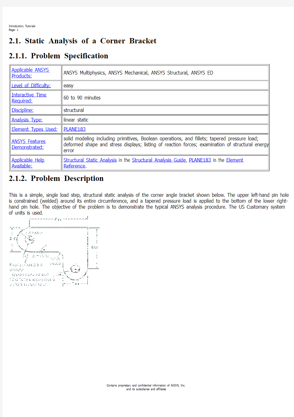
This is a simple, single load step, structural static analysis of the corner angle bracket shown below. The upper left-hand pin hole is constrained (welded) around its entire circumference, and a tapered pressure load is applied to the bottom of the lower righthand pin hole. The objective of the problem is to demonstrate the typical ANSYS analysis procedure. The US Customary system of units is used.
2.1.2.1. Given
The dimensions of the corner bracket are shown in the accompanying figure. The bracket is made of A36 steel with a Young’s modulus of 30E6 psi and Poisson’s ratio of .27.
2.1.2.2. Approach and Assumptions
Assume plane stress for this analysis. Since the bracket is thin in the z direction (1/2 inch thickness) compared to its x and y dimensions, and since the pressure load acts only in the x-y plane, this is a valid assumption. Your approach is to use solid modeling to generate the 2-D model and automatically mesh it with nodes and elements. (Another alternative in ANSYS is to create the nodes and elements directly.)
2.1.2.3. Summary of Steps
Contains proprietary and confidential information of ANSYS, Inc. and its subsidiaries and affiliates
利用 pdfFactory Pro 测试版本创建的PDF文档 https://www.doczj.com/doc/488691758.html,
Introductory Tutorials Page: 2
Use the information in the problem description and the steps below as a guideline in solving the problem on your own. Or, use the detailed interactive step-by-step solution by choosing the link for step 1.
Note: If your system includes a Flash player (from Macromedia, Inc.), you can view demonstration videos of each
step by pointing your web browser to the following URL address: http://www.ansys. com/techmedia/structural_tutorial_videos.html .
Build Geometry
1. Define rectangles. 2. Change plot controls and replot. 3. Change working plane to polar and create first circle. 4. Move working plane and create second circle. 5. Add areas. 6. Create line fillet. 7. Create fillet area. 8. Add areas together. 9. Create first pin hole. 10. Move working plane and create second pin hole. 11. Subtract pin holes from bracket. 12. Save the database as model.db.
Define Materials
13. Set Preferences. 14. Define Material Properties. 15. Define element types and options. 16. Define real constants.
Generate Mesh
17. Mesh the area. 18. Save the database as mesh.db.
Apply Loads
19. Apply displacement constraints. 20. Apply pressure load.
Obtain Solution
Contains proprietary and confidential information of ANSYS, Inc. and its subsidiaries and affiliates
利用 pdfFactory Pro 测试版本创建的PDF文档 https://www.doczj.com/doc/488691758.html,
Introductory Tutorials Page: 3
21. Solve.
Review Results
22. Enter the general postprocessor and read in the results. 23. Plot the deformed shape. 24. Plot the von Mises equivalent stress. 25. List the reaction solution. 26. Exit the ANSYS program.
2.1.3. Build Geometry
This is the beginning of Preprocessing.
2.1.3.1. Step 1: Define rectangles.
There are several ways to create the model geometry within ANSYS, some more convenient than others. The first step is to recognize that you can construct the bracket easily with combinations of rectangles and circle Primitives. Decide where the origin will be located and then define the rectangle and circle primitives relative to that origin. The location of the origin is arbitrary. Here, use the center of the upper left-hand hole. ANSYS does not need to know where the origin is. Simply begin by defining a rectangle relative to that location. In ANSYS, this origin is called the global origin. 1. Main Menu> Preprocessor> Modeling> Create> Areas> Rectangle> By Dimensions 2. Enter the following: X1 = 0 (Note: Press the Tab key between entries) X2 = 6 Y1 = -1 Y2 = 1 3. Apply to create the first rectangle. 4. Enter the following: X1 = 4 X2 = 6 Y1 = -1 Y2 = -3 5. OK to create the second rectangle and close the dialog box.
Contains proprietary and confidential information of ANSYS, Inc. and its subsidiaries and affiliates
利用 pdfFactory Pro 测试版本创建的PDF文档 https://www.doczj.com/doc/488691758.html,
Introductory Tutorials Page: 4
2.1.3.2. Step 2: Change plot controls and replot.
The area plot shows both rectangles, which are areas, in the same color. To more clearly distinguish between areas, turn on area numbers and colors. The "Plot Numbering Controls" dialog box on the Utility Menu controls how items are displayed in the Graphics Window. By default, a "replot" is automatically performed upon execution of the dialog box. The replot operation will repeat the last plotting operation that occurred (in this case, an area plot). 1. Utility Menu> Plot Ctrls> Numbering 2. Turn on area numbers. 3. OK to change controls, close the dialog box, and replot.
Before going to the next step, save the work you have done so far. ANSYS stores any input data in memory to the ANSYS database. To save that database to a file, use the SAVE operation, available as a tool on the Toolbar. ANSYS names the database file using the format jobname.db . If you started ANSYS using the product launcher, you can specify a jobname at that point (the default jobname is file). You can check the current jobname at any time by choosing Utility Menu> List> Status> Global Status. You can also save the database at specific milestone points in the analysis (such as after the model is complete, or after the model is meshed) by choosing Utility Menu> File> Save As and specifying different jobnames (model.db, or mesh.db, etc.). It is important to do an occasional save so that if you make a mistake, you can restore the model from the last saved state. You restore the model using the RESUME operation, also available on the Toolbar. (You can also find SAVE and RESUME on the Utility Menu, under File.) 4. Toolbar: SAVE_DB.
2.1.3.3. Step 3: Change working plane to polar and create first circle.
The next step in the model construction is to create the half circle at each end of the bracket. You will actually create a full circle on each end and then combine the circles and rectangles with a Boolean "add" operation (discussed in step 5.). To create the circles, you will use and display the working plane. You could have shown the working plane as you created the rectangles but it was not necessary.
Contains proprietary and confidential information of ANSYS, Inc. and its subsidiaries and affiliates
利用 pdfFactory Pro 测试版本创建的PDF文档 https://www.doczj.com/doc/488691758.html,
Introductory Tutorials Page: 5
Before you begin however, first "zoom out" within the Graphics Window so you can see more of the circles as you create them. You do this using the "Pan-Zoom-Rotate" dialog box, a convenient graphics control box you’ll use often in any ANSYS session.
1. 2. 3. 4.
Utility Menu> PlotCtrls> Pan, Zoom, Rotate Click on small dot once to zoom out. Close dialog box. Utility Menu> WorkPlane> Display Working Plane (toggle on)
5. 6. 7. 8. 9.
Notice the working plane origin is immediately plotted in the Graphics Window. It is indicated by the WX and WY symbols; right now coincident with the global origin X and Y symbols. Next you will change the WP type to polar, change the snap increment, and display the grid. Utility Menu> WorkPlane> WP Settings Click on Polar. Click on Grid and Triad. Enter .1 for snap increment. OK to define settings and close the dialog box.
10. Main Menu> Preprocessor> Modeling> Create> Areas> Circle> Solid Circle Be sure to read prompt before picking. 11. Pick center point at: WP X = 0 (in Graphics Window shown below) WP Y = 0 12. Move mouse to radius of 1 and click left button to create circle.
Contains proprietary and confidential information of ANSYS, Inc. and its subsidiaries and affiliates
利用 pdfFactory Pro 测试版本创建的PDF文档 https://www.doczj.com/doc/488691758.html,
Introductory Tutorials Page: 6
13. OK to close picking menu. 14. Toolbar: SAVE_DB.
Note: While you are positioning the cursor for picking, the "dynamic" WP X and Y values are displayed in the Solid
Circular Area dialog box. Also, as an alternative to picking, you can type these values along with the radius into the dialog box.
2.1.3.4. Step 4: Move working plane and create second circle.
To create the circle at the other end of the bracket in the same manner, you need to first move the working plane to the origin of the circle. The simplest way to do this without entering number offsets is to move the WP to an average keypoint location by picking the keypoints at the bottom corners of the lower, right rectangle. 1. Utility Menu> WorkPlane> Offset WP to> Keypoints 2. Pick keypoint at lower left corner of rectangle. 3. Pick keypoint at lower right of rectangle.
4. OK to close picking menu.
5. Main Menu> Preprocessor> Modeling> Create> Areas> Circle> Solid Circle 6. Pick center point at: WP X = 0 WP Y = 0 7. Move mouse to radius of 1 and click left button to create circle.
Contains proprietary and confidential information of ANSYS, Inc. and its subsidiaries and affiliates
利用 pdfFactory Pro 测试版本创建的PDF文档 https://www.doczj.com/doc/488691758.html,
Introductory Tutorials Page: 7
8. OK to close picking menu.
9. Toolbar: SAVE_DB.
2.1.3.5. Step 5: Add areas.
Now that the appropriate pieces of the model are defined (rectangles and circles), you need to add them together so the model becomes one continuous piece. You do this with the Boolean add operation for areas.
1. Main Menu> Preprocessor> Modeling> Operate> Booleans> Add> Areas 2. Pick All for all areas to be added.
3. Toolbar: SAVE_DB.
2.1.3.6. Step 6: Create line fillet.
1. Utility Menu> PlotCtrls> Numbering 2. Turn on line numbering. 3. OK to change controls, close the dialog box, and automatically replot.
4. Utility Menu> WorkPlane> Display Working Plane (toggle off)
Contains proprietary and confidential information of ANSYS, Inc. and its subsidiaries and affiliates
利用 pdfFactory Pro 测试版本创建的PDF文档 https://www.doczj.com/doc/488691758.html,
Introductory Tutorials Page: 8
Working Plane (toggle off)
5. Main Menu> Preprocessor> Modeling> Create> Lines> Line Fillet 6. Pick lines 17 and 8.
7. OK to finish picking lines (in picking menu). 8. Enter .4 as the radius. 9. OK to create line fillet and close the dialog box. 10. Utility Menu> Plot> Lines
2.1.3.7. Step 7: Create fillet area.
1. Utility Menu> PlotCtrls> Pan, Zoom, Rotate 2. Click on Zoom button. 3. Move mouse to fillet region, click left button, move mouse out and click again.
4. Main Menu> Preprocessor> Modeling> Create> Areas> Arbitrary> By Lines
Contains proprietary and confidential information of ANSYS, Inc. and its subsidiaries and affiliates
利用 pdfFactory Pro 测试版本创建的PDF文档 https://www.doczj.com/doc/488691758.html,
Introductory Tutorials Page: 9
5. Pick lines 4, 5, and 1.
6. 7. 8. 9.
OK to create area and close the picking menu. Click on Fit button. Close the Pan, Zoom, Rotate dialog box. Utility Menu> Plot> Areas
10. Toolbar: SAVE_DB.
2.1.3.8. Step 8: Add areas together.
1. Main Menu> Preprocessor> Modeling> Operate> Booleans> Add> Areas 2. Pick All for all areas to be added.
3. Toolbar: SAVE_DB.
2.1.3.9. Step 9: Create first pin hole.
Contains proprietary and confidential information of ANSYS, Inc. and its subsidiaries and affiliates
利用 pdfFactory Pro 测试版本创建的PDF文档 https://www.doczj.com/doc/488691758.html,
Introductory Tutorials Page: 10
1. Utility Menu> WorkPlane> Display Working Plane (toggle on)
2. Main Menu> Preprocessor> Modeling> Create> Areas> Circle> Solid Circle 3. Pick center point at: WP X = 0 (in Graphics Window) WP Y = 0 4. Move mouse to radius of .4 (shown in the picking menu) and click left button to create circle. 5. OK to close picking menu.
2.1.3.10. Step 10: Move working plane and create second pin hole.
1. Utility Menu> WorkPlane> Offset WP to> Global Origin 2. Main Menu> Preprocessor> Modeling> Create> Areas> Circle> Solid Circle 3. Pick center point at: WP X = 0 (in Graphics Window) WP Y = 0 4. 5. 6. 7. Move mouse to radius of .4 (shown in the picking menu) and click left mouse button to create circle. OK to close picking menu. Utility Menu> WorkPlane> Display Working Plane (toggle off) Utility Menu> Plot> Replot
From this area plot, it appears that one of the pin hole areas is not there. However, it is there (as indicated by the presence of its lines), you just can't see it in the final display of the screen. That is because the bracket area is drawn on top of it. An easy way to see all areas is to plot the lines instead. 8. Utility Menu> Plot> Lines
9. Toolbar: SAVE_DB.
2.1.3.11. Step 11: Subtract pin holes from bracket.
1. 2. 3. 4. Main Menu> Preprocessor> Modeling> Operate> Booleans> Subtract> Areas Pick bracket as base area from which to subtract. Apply (in picking menu). Pick both pin holes as areas to be subtracted.
Contains proprietary and confidential information of ANSYS, Inc. and its subsidiaries and affiliates
利用 pdfFactory Pro 测试版本创建的PDF文档 https://www.doczj.com/doc/488691758.html,
Introductory Tutorials Page: 11
5. OK to subtract holes and close picking menu.
2.1.3.12. Step 12: Save the database as model.db.
At this point, you will save the database to a named file -- a name that represents the model before meshing. If you decide to go back and remesh, you'll need to resume this database file. You will save it as model.db.
1. Utility Menu> File> Save As 2. Enter model.db for the database file name. 3. OK to save and close dialog box.
2.1.4. Define Materials
2.1.4.1. Step 13: Set preferences.
In preparation for defining materials, you will set preferences so that only materials that pertain to a structural analysis are available for you to choose. To set preferences:
1. Main Menu> Preferences 2. Turn on structural filtering. The options may differ from what is shown here since they depend on the ANSYS product you are using. 3. OK to apply filtering and close the dialog box.
Contains proprietary and confidential information of ANSYS, Inc. and its subsidiaries and affiliates
利用 pdfFactory Pro 测试版本创建的PDF文档 https://www.doczj.com/doc/488691758.html,
Introductory Tutorials Page: 12
2.1.4.2. Step 14: Define material properties.
To define material properties for this analysis, there is only one material for the bracket, A36 Steel, with given values for Young’ s modulus of elasticity and Poisson’s ratio.
1. Main Menu> Preprocessor> Material Props> Material Models 2. Double-click on Structural, Linear, Elastic, Isotropic. 3. Enter 30e6 for EX. 4. Enter .27 for PRXY. 5. OK to define material property set and close the dialog box. 6. Material> Exit
2.1.4.3. Step 15: Define element types and options.
Contains proprietary and confidential information of ANSYS, Inc. and its subsidiaries and affiliates
利用 pdfFactory Pro 测试版本创建的PDF文档 https://www.doczj.com/doc/488691758.html,
Introductory Tutorials Page: 13
In any analysis, you need to select from a library of element types and define the appropriate ones for your analysis. For this analysis, you will use only one element type, PLANE183, which is a 2-D, quadratic, structural, higher-order element. The choice of a higher-order element here allows you to have a coarser mesh than with lower-order elements while still maintaining solution accuracy. Also, ANSYS will generate some triangle shaped elements in the mesh that would otherwise be inaccurate if you used lower-order elements. You will need to specify plane stress with thickness as an option for PLANE183. (You will define the thickness as a real constant in the next step.)
1. Main Menu> Preprocessor> Element Type> Add/Edit/Delete 2. Add an element type. 3. Structural solid family of elements. 4. Choose the 8-node quad (PLANE183). 5. OK to apply the element type and close the dialog box. 6. Options for PLANE183 are to be defined. 7. Choose plane stress with thickness option for element behavior. 8. OK to specify options and close the options dialog box. 9. Close the element type dialog box.
Contains proprietary and confidential information of ANSYS, Inc. and its subsidiaries and affiliates
利用 pdfFactory Pro 测试版本创建的PDF文档 https://www.doczj.com/doc/488691758.html,
Introductory Tutorials Page: 14
2.1.4.4. Step 16: Define real constants.
For this analysis, since the assumption is plane stress with thickness, you will enter the thickness as a real constant for PLANE183. To find out more information about PLANE183, you will use the ANSYS Help System in this step by clicking on a Help button from within a dialog box.
1. Main Menu> Preprocessor> Real Constants> Add/Edit/Delete 2. Add a real constant set. 3. OK for PLANE183. Before clicking on the Help button in the next step, you should be aware that the help information may appear in the same window as this tutorial, replacing the
Contains proprietary and confidential information of ANSYS, Inc. and its subsidiaries and affiliates
利用 pdfFactory Pro 测试版本创建的PDF文档 https://www.doczj.com/doc/488691758.html,
Introductory Tutorials Page: 15
4. 5. 6.
7. 8. 9.
contents of the tutorial. After reading the help information, click on the Back button to return to this tutorial. If the help information appears in a separate window from the tutorial, minimize or close the help window after you read the help information. Help to get help on PLANE183. Hold left mouse button down to scroll through element description. If the help information replaced the tutorial, click on the Back button to return to the tutorial. Enter .5 for THK. OK to define the real constant and close the dialog box. Close the real constant dialog box.
2.1.5. Generate Mesh
2.1.5.1. Step 17: Mesh the area.
One nice feature of the ANSYS program is that you can automatically mesh the model without specifying any mesh size controls. This is using what is called a default mesh. If you’re not sure how to determine the mesh density, let ANSYS try it first! Meshing this model with a default mesh however, generates more elements than are allowed in the ANSYS ED program. Instead you will specify a global element size to control overall mesh density.
Contains proprietary and confidential information of ANSYS, Inc. and its subsidiaries and affiliates
利用 pdfFactory Pro 测试版本创建的PDF文档 https://www.doczj.com/doc/488691758.html,
Introductory Tutorials Page: 16
1. Main Menu> Preprocessor> Meshing> Mesh Tool 2. Set Global Size control. 3. Type in 0.5. 4. OK. 5. Choose Area Meshing. 6. Click on Mesh. 7. Pick All for the area to be meshed (in picking menu). Close any warning messages that appear. 8. Close the Mesh Tool.
Note: The mesh you see on your screen may vary slightly from the mesh shown here. As a result of this, you may
see slightly different results during postprocessing. For a discussion of results accuracy, see Planning Your Approach in the Modeling and Meshing Guide.
2.1.5.2. Step 18: Save the database as mesh.db.
Here again, you will save the database to a named file, this time mesh.db.
1. Utility Menu> File> Save as 2. Enter mesh.db for database file name. 3. OK to save file and close dialog box.
Contains proprietary and confidential information of ANSYS, Inc. and its subsidiaries and affiliates
利用 pdfFactory Pro 测试版本创建的PDF文档 https://www.doczj.com/doc/488691758.html,
Introductory Tutorials Page: 17
2.1.6. Apply Loads
The beginning of the solution phase. A new, static analysis is the default, so you will not need to specify analysis type for this problem. Also, there are no analysis options for this problem.
2.1.6.1. Step 19: Apply displacement constraints.
You can apply displacement constraints directly to lines. 1. Main Menu> Solution> Define Loads> Apply> Structural> Displacement> On Lines 2. Pick the four lines around left-hand hole (Line numbers 10, 9, 11, 12).
3. 4. 5. 6. 7.
OK (in picking menu). Click on All DOF. Enter 0 for zero displacement. OK to apply constraints and close dialog box. Utility Menu> Plot Lines
8. Toolbar: SAVE_DB.
2.1.6.2. Step 20: Apply pressure load.
Now apply the tapered pressure load to the bottom, right-hand pin hole. ("Tapered" here means varying linearly.) Note that when a circle is created in ANSYS, four lines define the perimeter. Therefore, apply the pressure to two lines making up the lower half of the circle. Since the pressure tapers from a maximum value (500 psi) at the bottom of the circle to a minimum value (50 psi) at the sides, apply pressure in two separate steps, with reverse tapering values for each line. The ANSYS convention for pressure loading is that a positive load value represents pressure into the surface (compressive).
Contains proprietary and confidential information of ANSYS, Inc. and its subsidiaries and affiliates
利用 pdfFactory Pro 测试版本创建的PDF文档 https://www.doczj.com/doc/488691758.html,
Introductory Tutorials Page: 18
1. Main Menu> Solution> Define Loads> Apply> Structural> Pressure> On Lines 2. Pick line defining bottom left part of the circle (line 6).
3. 4. 5. 6. 7.
Apply. Enter 50 for VALUE. Enter 500 for optional value. Apply. Pick line defining bottom right part of circle (line 7).
8. 9. 10. 11.
Apply. Enter 500 for VALUE. Enter 50 for optional value. OK.
12. Toolbar: SAVE_DB.
Contains proprietary and confidential information of ANSYS, Inc. and its subsidiaries and affiliates
利用 pdfFactory Pro 测试版本创建的PDF文档 https://www.doczj.com/doc/488691758.html,
Introductory Tutorials Page: 19
2.1.7. Obtain Solution
2.1.7.1. Step 21: Solve.
1. Main Menu> Solution> Solve> Current LS 2. Review the information in the status window, then choose File> Close (Windows), or Close (X11/Motif), to close the window. 3. OK to begin the solution. Choose Yes to any Verify messages that appear. 4. Close the information window when solution is done.
ANSYS stores the results of this one load step problem in the database and in the results file, Jobname.RST (or Jobname.RTH for thermal, Jobname.RMG for magnetic, and Jobname.RFL for fluid analyses). The database can actually contain only one set of results at any given time, so in a multiple load step or multiple substep analysis, ANSYS stores only the final solution in the database. ANSYS stores all solutions in the results file.
Contains proprietary and confidential information of ANSYS, Inc. and its subsidiaries and affiliates
利用 pdfFactory Pro 测试版本创建的PDF文档 https://www.doczj.com/doc/488691758.html,
Introductory Tutorials Page: 20
2.1.8. Review Results
The beginning of the postprocessing phase.
Note: The results you see may vary slightly from what is shown here due to variations in the mesh.
2.1.8.1. Step 22: Enter the general postprocessor and read in the results.
1. Main Menu> General Postproc> Read Results> First Set
2.1.8.2. Step 23: Plot the deformed shape.
1. Main Menu> General Postproc> Plot Results> Deformed Shape 2. Choose Def + undeformed. 3. OK.
You can also produce an animated version of the deformed shape: 4. Utility Menu> Plot Ctrls> Animate> Deformed Shape 5. Choose Def + undeformed. 6. OK.
7. Make choices in the Animation Controller (not shown), if necessary, then choose Close.
2.1.8.3. Step 24: Plot the von Mises equivalent stress.
1. Main Menu> General Postproc> Plot Results> Contour Plot> Nodal Solu 2. Choose Stress item to be contoured. 3. Scroll down and choose von Mises (SEQV). 4. OK.
You can also produce an animated version
Contains proprietary and confidential information of ANSYS, Inc. and its subsidiaries and affiliates
利用 pdfFactory Pro 测试版本创建的PDF文档 https://www.doczj.com/doc/488691758.html,
“有限元分析及应用”课程有限元分析软件ANSYS6.xed 上机指南 清华大学机械工程系 2002年9月
说明 本《有限元分析软件ANSYS6.1ed:上机指南》由清华大学机械工程系石伟老师组织编写,由助教博士生孔劲执笔, 于2002年9月完成,基本操作指南中的所有算例都在相应的软件系统中进行了实际调试和通过。 本上机指南的版权归清华大学机械工程系所有,未经同意,任何单位和个人不得翻印。
目录 Project1 简支梁的变形分析 (1) Project2 坝体的有限元建模与受力分析 (3) Project3 受内压作用的球体的应力与变形分析 (5) Project4 受热载荷作用的厚壁圆筒的有限元建模与温度场求解 (7) Project5 超静定桁架的有限元求解 (9) Project6 超静定梁的有限元求解 (11) Project7 平板的有限元建模与变形分析 (13)
Project1 梁的有限元建模与变形分析 计算分析模型如图1-1 所示, 习题文件名: beam。 NOTE:要求选择不同形状的截面分别进行计算。 梁承受均布载荷:1.0e5 Pa 图1-1梁的计算分析模型 梁截面分别采用以下三种截面(单位:m): 矩形截面:圆截面:工字形截面: B=0.1, H=0.15 R=0.1 w1=0.1,w2=0.1,w3=0.2, t1=0.0114,t2=0.0114,t3=0.007 1.1进入ANSYS 程序→ANSYSED 6.1 →Interactive →change the working directory into yours →input Initial jobname: beam→Run 1.2设置计算类型 ANSYS Main Menu: Preferences →select Structural →OK 1.3选择单元类型 ANSYS Main Menu: Preprocessor →Element Type→Add/Edit/Delete… →Add… →select Beam 2 node 188 →OK (back to Element Types window)→Close (the Element Type window) 1.4定义材料参数 ANSYS Main Menu: Preprocessor →Material Props →Material Models →Structural→Linear→Elastic→Isotropic→input EX:2.1e11, PRXY:0.3→OK 1.5定义截面 ANSYS Main Menu: Preprocessor →Sections →Beam →Common Sectns→分别定义矩形截面、圆截面和工字形截面:矩形截面:ID=1,B=0.1,H=0.15 →Apply →圆截面:ID=2,R=0.1 →Apply →工字形截面:ID=3,w1=0.1,w2=0.1,w3=0.2,t1=0.0114,t2=0.0114,t3=0.007→OK
轴承座 轴瓦 轴 四个安装孔径 轴承座底部约 沉孔上的推力 向下作用力 ANSYS 基础培训练习题 第一日 练习主题:实体建模 EX1:轴承座的实体建模、网格划分、加载、求解及后处理 练习目的:创建实体的方法,工作平面的平移及旋转,布尔运算(相减、粘接、搭接,模型体素的合并,基本网格划分。基本加 载、求解及后 处 理。 问题描述: 具体步骤: 轴承系统 (分解图) 载荷
首先进入前处理(/PREP7) 1. 创建基座模型 生成长方体 Main Menu:Preprocessor>Modeling>Create>Volumes>Block>By Dimensions 输入x1=0,x2=3,y1=0,y2=1,z1=0,z2=3 平移并旋转工作平面 Utility Menu>WorkPlane>Offset WP by Increments X,Y,Z Offsets 输入2.25,1.25,.75 点击Apply XY,YZ,ZX Angles输入0,-90点击OK。 创建圆柱体 Main Menu:Preprocessor>Modeling>Creat>Cylinder> Solid Cylinder075 Radius输入0.75/2, Depth输入-1.5,点击OK。 拷贝生成另一个圆柱体 Main Menu:Preprocessor>Modeling>Copy>Volume拾取圆柱体,点击Apply, DZ输入1.5然后点击OK
从长方体中减去两个圆柱体 Main Menu:Preprocessor>Modeling>Operate>Booleans>Subtract>Volumes首先拾取被减的长方体,点击Apply,然后拾取减去的两个圆柱体,点击OK。 使工作平面与总体笛卡尔坐标系一致 Utility Menu>WorkPlane>Align WP with> Global Cartesian 2. 创建支撑部分Utility Menu: WorkPlane -> Display Working Plane (toggle on) Main Menu: Preprocessor -> -Modeling-Create -> -Volumes-Block -> By 2 corners & Z 在创建实体块的参数表中输入下列数值: WP X = 0 WP Y = 1 Width = 1.5 Height = 1.75 Depth = 0.75 OK Toolbar: SAVE_DB 3. 偏移工作平面到轴瓦支架的前表面 Utility Menu: WorkPlane -> Offset WP to -> Keypoints + 1. 在刚刚创建的实体块的左上角拾取关键点 2. OK Toolbar: SAVE_DB
第5章动力学分析 结构动力学研究的是结构在随时间变化载荷下的响应问题,它与静力分析的主要区别是动力分析需要考虑惯性力以及运动阻力的影响。动力分析主要包括以下5个部分:模态分析:用于计算结构的固有频率和模态。 谐波分析(谐响应分析):用于确定结构在随时间正弦变化的载荷作用下的响应。 瞬态动力分析:用于计算结构在随时间任意变化的载荷作用下的响应,并且可涉及上述提到的静力分析中所有的非线性性质。 谱分析:是模态分析的应用拓广,用于计算由于响应谱或PSD输入(随机振动)引起的应力和应变。 显式动力分析:ANSYS/LS-DYNA可用于计算高度非线性动力学和复杂的接触问题。 本章重点介绍前三种。 【本章重点】 ?区分各种动力学问题; ?各种动力学问题ANSYS分析步骤与特点。 5.1 动力学分析的过程与步骤 模态分析与谐波分析两者密切相关,求解简谐力作用下的响应时要用到结构的模态和振型。瞬态动力分析可以通过施加载荷步模拟各种何载,进而求解结构响应。三者具体分析过程与步骤有明显区别。 5.1.1 模态分析 1.模态分析应用 用模态分析可以确定一个结构的固有频率利振型,固有频率和振型是承受动态载荷结构设计中的重要参数。如果要进行模态叠加法谐响应分析或瞬态动力学分析,固有频率和振型也是必要的。可以对有预应力的结构进行模态分析,例如旋转的涡轮叶片。另一个有用的分析功能是循环对称结构模态分析,该功能允许通过仅对循环对称结构的一部分进行建模,而分析产生整个结构的振型。 ANSYS产品家族的模态分析是线性分析,任何非线性特性,如塑性和接触(间隙)单元,即使定义也将被忽略。可选的模态提取方法有6种,即Block Lanczos(默认)、Subspace、Power Dynamics、Reduced、Unsymmetric、Damped及QR Damped,后两种方法允许结构中包含阻尼。 2.模态分析的步骤
第一部分自由网格划分 (1)确定单元类型 GUI:执行“Main Menu→Preprocessor→Element Type→Add/Edit/Delete”菜单命令。 执行上命令后,打开如下左图所示对话框。在左图中单击(Add)按钮,打开右图对话框,然后再左侧的窗口中选取“Solid”单元,右侧窗口中选取“10node 92”单元。 (2)建立几何模型 GUI:执行“Main Menu→Preprocessor→Create→Volumes→Block→By Dimensions”菜单命令,在弹出的对话框中输入“X1=0,X2=4,Y1=0,Y2=4,Z1=0,Z2=4”,得到立方体。 执行“Main Menu→Preprocessor→Create→Volumes→Cylinder→Solid Cylinder” 菜单命令,在弹出的对话框中输入“X=2,Y=2,Radius=0.5,Depth=6”,得到圆柱体。如下图:
(3)布尔加运算 GUI:执行“Main Menu→Preprocessor→Modeling→Operate→Booleans-Add→Volumes”菜单命令。执行命令后,将打开如图的对话框中单击(Pick All)按钮,将所有面积组合在一起。如上图。 (4)自由网格划分 GUI:执行“Main Menu→Preprocessor→Meshing→Mesh Tool”菜单命令,在弹出 的对话框中选择“Global→set”,接着在对话框中输入“SIZE=0,NDIV=10”,如图: 得到自由网格划分结果如下图:
第二部分映射网格划分 (1)确定单元类型 GUI:执行“Main Menu→Preprocessor→Element Type→Add/Edit/Delete”菜单命令。 执行上命令后,打开如下左图所示对话框。在左图中单击(Add)按钮,打开右图对话框,然后再左侧的窗口中选取“Magnetic-Edge”单元,右侧窗口中选取“3D Brick 117”单元。
平面问题斜支座的处理 如图5-7所示,为一个带斜支座的平面应力结构,其中位置2及3处为固定约束,位置4处为一个45o的斜支座,试用一个4节点矩形单元分析该结构的位移场。 (a)平面结构(b)有限元分析模型 图5-7 带斜支座的平面结构 基于ANSYS平台,分别采用约束方程以及局部坐标系的斜支座约束这两种方式来进行处理。 (7) 模型加约束 左边施加X,Y方向的位移约束 ANSYS Main Menu: Solution →Define Loads →Apply →-Structural→Displacement On Nodes →选取2,3号节点→OK →Lab2: All DOF(施加X,Y方向的位移约束) →OK 以下提供两种方法处理斜支座问题,使用时选择一种方法。 ?采用约束方程来处理斜支座 ANSYS Main Menu:Preprocessor →Coupling/ Ceqn →Constraint Eqn :Const :0, NODE1:4, Lab1: UX,C1:1,NODE2:4,Lab2:UY,C2:1→OK 或者?采用斜支座的局部坐标来施加位移约束 ANSYS Utility Menu:WorkPlane →Local Coordinate System →Create local system →At specified LOC + →单击图形中的任意一点→OK →XC、YC、ZC分别设定为2,0,0,THXY:45 →OK ANSYS Main Menu:Preprocessor →modeling →Move / Modify →Rotate Node CS →To active CS → 选择4号节点 ANSYS Main Menu:Solution →Define Loads →Apply →Structural →Displacement On Nodes →选取4号节点→OK →选择Lab2:UY(施加Y方向的位移约束) →OK 命令流; !---方法1 begin----以下的一条命令为采用约束方程的方式对斜支座进行处理 CE,1,0,4,UX,1,4,UY,-1 !建立约束方程(No.1): 0=node4_UX*1+node_UY*(-1) !---方法1 end --- !--- 方法2 begin --以下三条命令为定义局部坐标系,进行旋转,施加位移约束 !local,11,0,2,0,0,45 !在4号节点建立局部坐标系 !nrotat, 4 !将4号节点坐标系旋转为与局部坐标系相同 !D,4,UY !在局部坐标下添加位移约束 !--- 方法2 end
输气管道受力分析(ANSYS建模) 任务和要求: 按照输气管道的尺寸及载荷情况,要求在ANSYS中建模,完成整个静力学分析过程。求出管壁的静力场分布。要求完成问题分析、求解步骤、程序代码、结果描述和总结五部分。所给的参数如下: 材料参数:弹性模量E=200Gpa; 泊松比0.26;外径R?=0.6m;内径R?=0.4m;壁厚t=0.2m。输气管体内表面的最大冲击载荷P为1Mpa。 四.问题求解 (一).问题分析 由于管道沿长度方向的尺寸远大于管道的直径,在计算过程中忽略管道的端面效应,认为在其长度方向无应变产生,即可将该问题简化为平面应变问题,选取管道横截面建立几何模型进行求解。 (二).求解步骤 定义工作文件名 选择Utility Menu→File→Chang Jobname 出现Change Jobname对话框,在[/FILNAM] Enter new jobname 输入栏中输入工作名LEILIN10074723,并将New log and eror file 设置为YES,单击[OK]按钮关闭对话框 定义单元类型 1)选择Main Meun→Preprocessor→Element Type→Add/Edit/Delte命令,出现Element Type 对话框,单击[Add]按钮,出现Library of Element types对话框。 2)在Library of Element types复选框选择Strctural、Solid、 Quad 8node 82,在Element type reference number输入栏中出入1,单击[OK]按钮关闭该对话框。 3. 定义材料性能参数 1)单击Main Meun→Preprocessor→Material Props→Material models出现Define Material Behavion 对话框。选择依次选择Structural、Linear、Elastic、Isotropic选项,出现Linear Isotropic Material Properties For Material Number 1对话框。 2)在EX输入2e11,在Prxy输入栏中输入0.26,单击OK按钮关闭该对话框。 3)在Define Material Model Behavion 对话框中选择Material→Exit命令关闭该对话框。 4.生成几何模型、划分网格 1)选择Main Meun→Preprocessor→Modeling→Create→Areas→Circle→Partail→Annulus出现Part Annulus Circ Area对话框,在WP X文本框中输入0,在WP Y文本框中输入0,在Rad1文本框中输入0.4,在Theate-1文本框中输入0,在Rad2文本框中输入0.6,在Theate-2文本框中输入90,单击OK按钮关闭该对话框。 2)选择Utility Menu→Plotctrls→Style→Colors→Reverse Video,设置显示颜色。 3)选择Utility Menu→Plot→Areas,显示所有面。 4) 选择Main Menu→Preprocessor→Modeling→Reflect→Areas,出现Reflect Areas拾取菜
第一章模态分析 §模态分析的定义及其应用 模态分析用于确定设计结构或机器部件的振动特性(固有频率和振型),即结构的固有频率和振型,它们是承受动态载荷结构设计中的重要参数。同时,也可以作为其它动力学分析问题的起点,例如瞬态动力学分析、谐响应分析和谱分析,其中模态分析也是进行谱分析或模态叠加法谐响应分析或瞬态动力学分析所必需的前期分析过程。 ANSYS的模态分析可以对有预应力的结构进行模态分析和循环对称结构模态分析。前者有旋转的涡轮叶片等的模态分析,后者则允许在建立一部分循环对称结构的模型来完成对整个结构的模态分析。 ANSYS产品家族中的模态分析是一个线性分析。任何非线性特性,如塑性和接触(间隙)单元,即使定义了也将被忽略。ANSYS提供了七种模态提取方法,它们分别是子空间法、分块Lanczos法、PowerDynamics法、缩减法、非对称法、阻尼法和QR阻尼法。阻尼法和QR阻尼法允许在结构中存在阻尼。后面将详细介绍模态提取方法。 §模态分析中用到的命令 模态分析使用所有其它分析类型相同的命令来建模和进行分析。同样,无论进行何种类型的分析,均可从用户图形界面(GUI)上选择等效于命令的菜单选项来建模和求解问题。 后面的“模态分析实例(命令流或批处理方式)”将给出进行该实例模态分析时要输入的命令(手工或以批处理方式运行ANSYS时)。而“模态分析实例(GUI方式)” 则给出了以从ANSYS GUI中选择菜单选项方式进行同一实例分析的步骤。(要想了解如何使用命令和GUI选项建模,请参阅<
练习一梁的有限元建模与变形分析 计算分析模型如图1-1 所示, 习题文件名: beam。 NOTE:要求选择不同形状的截面分别进行计算。 梁承受均布载荷:1.0e5 Pa 10m 图1-1梁的计算分析模型 梁截面分别采用以下三种截面(单位:m): 矩形截面:圆截面:工字形截面: B=0.1, H=0.15 R=0.1 w1=0.1,w2=0.1,w3=0.2, t1=0.0114,t2=0.0114,t3=0.007 1.1进入ANSYS 程序→ANSYSED →Interactive →change the working directory into yours →input Initial jobname: beam→Run 1.2设置计算类型 ANSYS Main Menu: Preferences →select Structural →OK 1.3选择单元类型 ANSYS Main Menu: Preprocessor →Element Type→Add/Edit/Delete… →Add… →select Beam 2 node 188 →OK (back to Element Types window)→Close (the Element Type window) 1.4定义材料参数 ANSYS Main Menu: Preprocessor →Material Props →Material Models →Structural→Linear→Elastic→Isotropic→input EX:2.1e11, PRXY:0.3→OK 1.5定义截面 ANSYS Main Menu: Preprocessor →Sections →Beam →Common Sectns→分别定义矩形截面、圆截面和工字形截面:矩形截面:ID=1,B=0.1,H=0.15 →Apply →圆截面:ID=2,R=0.1 →Apply →工字形截面:ID=3,w1=0.1,w2=0.1,w3=0.2,t1=0.0114,t2=0.0114,t3=0.007→OK
《有限元法及其应用》课程作业ANSYS应用分析 学号: 姓名: 专业:建筑与土木工程
角托架的有限元建模与分析 一 、模型介绍 本模型是关于一个角托架的简单加载,线性静态结构分析问题,托架的具体形状和尺寸如图所示。托架左上方的销孔被焊接完全固定,其右下角的销孔受到锥形压力载荷,角托架材料为Q235A 优质钢。角托架材料参数为:弹性模量366E e psi =;泊松比0.27ν= 托架图(厚度:0.5) 二、问题分析 因为角托架在Z 方向尺寸相对于其在X,Y 方向的尺寸来说很小,并且压力荷载仅作用在X,Y 平面上,因此可以认为这个分析为平面应力状态。 三、模型建立 3.1 指定工作文件名和分析标题 (1)选择菜单栏Utility Menu → 命令.系统将弹出Jobname(修改文件名)对话框,输入bracket (2)定义分析标题 GUI :Utility Menu>Preprocess>Element Type>Add/Edit/Delete 执行命令后,弹出对话框,输入stress in a bracket 作为ANSYS 图形显示时的标题。 3.2设置计算类型 Main Menu: Preferences … →select Structural → OK 3.3定义单元类型 PLANE82 GUI :Main Menu →Preprocessor →Element Type →Add/Edit/Delete 命令,系统将弹出Element Types 对话框。单击Add 按钮,在对话框左边的下拉列表中单击Structural Solid →Quad 8node 82,选择8节点平面单元PLANE82。单击ok ,Element Types 对话框,单击Option ,在Element behavior 后面窗口中选取Plane strs w/thk 后单击ok 完成定义单元类型。 3.4定义单元实常数 GUI :Main Menu: Preprocessor →Real Constants →Add/Edit/Delete ,弹出定义实常数对话框,单击Add ,弹出要定义实常数单元对话框,选中PLANE82单元后,单击OK →定义单元厚度对话框,在THK 中输入0.5.
Introductory Tutorials Page: 1
2.1. Static Analysis of a Corner Bracket 2.1.1. Problem Specification
Applicable ANSYS Products: Level of Difficulty: Interactive Time Required: Discipline: Analysis Type: Element Types Used: ANSYS Features Demonstrated: Applicable Help Available: ANSYS Multiphysics, ANSYS Mechanical, ANSYS Structural, ANSYS ED easy 60 to 90 minutes structural linear static PLANE183 solid modeling including primitives, Boolean operations, and fillets; tapered pressure load; deformed shape and stress displays; listing of reaction forces; examination of structural energy error Structural Static Analysis in the Structural Analysis Guide, PLANE183 in the Element Reference.
2.1.2. Problem Description
This is a simple, single load step, structural static analysis of the corner angle bracket shown below. The upper left-hand pin hole is constrained (welded) around its entire circumference, and a tapered pressure load is applied to the bottom of the lower righthand pin hole. The objective of the problem is to demonstrate the typical ANSYS analysis procedure. The US Customary system of units is used.
2.1.2.1. Given
The dimensions of the corner bracket are shown in the accompanying figure. The bracket is made of A36 steel with a Young’s modulus of 30E6 psi and Poisson’s ratio of .27.
2.1.2.2. Approach and Assumptions
Assume plane stress for this analysis. Since the bracket is thin in the z direction (1/2 inch thickness) compared to its x and y dimensions, and since the pressure load acts only in the x-y plane, this is a valid assumption. Your approach is to use solid modeling to generate the 2-D model and automatically mesh it with nodes and elements. (Another alternative in ANSYS is to create the nodes and elements directly.)
2.1.2.3. Summary of Steps
Contains proprietary and confidential information of ANSYS, Inc. and its subsidiaries and affiliates
利用 pdfFactory Pro 测试版本创建的PDF文档 https://www.doczj.com/doc/488691758.html,
实例1: 某一潜水艇可以简化为一圆筒,它由三层组成,最外面一层为不锈钢,中间为玻纤隔热层,最里面为铝层,筒内为空气,筒外为海水,求内外壁面温度及温度分布。 几何参数:筒外径30 feet 总壁厚 2 inch 不锈钢层壁厚0.75 i nch 玻纤层壁厚 1 inch 铝层壁厚0.25 i nch 筒长200 feet 导热系数不锈钢8.27 B TU/hr.ft.o F 玻纤0.028 BTU/hr.ft.o F 铝117.4 BTU/hr.ft.o F 边界条件空气温度70 o F 海水温度44.5 o F 空气对流系数 2.5 BTU/hr.ft2.o F 海水对流系数80 BTU/hr.ft2.o F 沿垂直于圆筒轴线作横截面,得到一圆环,取其中1度进行分析,如图示。 以下分别列出log文件和菜单文件。 /filename, Steady1 /title, Steady-state thermal analysis of submarine /units, BFT Ro=15 !外径(ft)
Rss=15-(0.75/12) !不锈钢层内径ft) Rins=15-(1.75/12) !玻璃纤维层内径(ft) Ral=15-(2/12) !铝层内径(ft) Tair=70 !潜水艇内空气温度 Tsea=44.5 !海水温度 Kss=8.27 !不锈钢的导热系数(BTU/hr.ft.oF) Kins=0.028 !玻璃纤维的导热系数(BTU/hr.ft.oF) Kal=117.4 !铝的导热系数(BTU/hr.ft.oF) Hair=2.5 !空气的对流系数(BTU/hr.ft2.oF) Hsea=80 !海水的对流系数(BTU/hr.ft2.oF) /prep7 et,1,plane55 !定义二维热单元 mp,kxx,1,Kss !设定不锈钢的导热系数 mp,kxx,2,Kins !设定玻璃纤维的导热系数 mp,kxx,3,Kal !设定铝的导热系数 pcirc,Ro,Rss,-0.5,0.5 !创建几何模型 pcirc,Rss,Rins,-0.5,0.5 pcirc,Rins,Ral,-0.5,0.5 aglue,all numcmp,area lesize,1,,,16 !设定划分网格密度 lesize,4,,,4 lesize,14,,,5 lesize,16,,,2 eshape,2 !设定为映射网格划分 mat,1 amesh,1 mat,2 amesh,2 mat,3 amesh,3 /SOLU SFL,11,CONV,HAIR,,TAIR !施加空气对流边界
ansys钢筋混凝土建模实例 finish /clear /prep7 et,1,solid65,,,,,,,1 et,2,link8 et,3,185 et,4,solid45 !************************定义材料属性***************************** !混凝土材料属性 mp,ex,1,1.596e10 mp,prxy,1,0.2 mp,dens,1,2400 fc=1.68e7 !c30混凝土轴心抗压强度设计值 ft=1.86e6 tb,concr,1 tbdata,,0.5,0.95,ft,-1 tb,miso,1,,11 tbpt,,0.0002,fc*0.19 tbpt,,0.0004,fc*0.36 tbpt,,0.0006,fc*0.51 tbpt,,0.0008,fc*0.64 tbpt,,0.0010,fc*0.75 tbpt,,0.0012,fc*0.84 tbpt,,0.0014,fc*0.91 tbpt,,0.0016,fc*0.96 tbpt,,0.0018,fc*0.99 tbpt,,0.002,fc tbpt,,0.0033,fc !57到68 v,6,7,56,54,10,11,60,58 vgen,4,57,57,1,0,0.38,0 vgen,2,57,60,1,0.25,0,0 vgen,2,57,60,1,-0.25,0,0 !69到80 v,189,190,234,233,191,192,238,237 vgen,4,69,69,1,0,0.38,0
vgen,3,69,72,1,0,0,0.25 !121到136 vgen,2,105,120,1,0,0,0.107 !193到208 k,1178,0.81,0,0.107 k,1179,0.823,0,0.107 k,1180,0.81,0,0.417 k,1181,0.81,0.16,0.107 k,1182,0.823,0.16,0.107 k,1183,0.81,0.16,0.417 k,1184,0.81,0.38,0.107 k,1185,0.823,0.38,0.107 k,1186,0.81,0.38,0.417 v,1178,1179,187,1180,1181,1182,189,1183 v,1181,1182,189,1183,1184,1185,191,1186 vgen,4,193,194,1,0,0.38,0 vgen,2,193,200,1,0.107,0,0 !209到232 k,1271,-0.02,0,-0.013 k,1272,-0.02,0,0 k,1273,-0.02,0.16,-0.013 k,1274,-0.02,0.16,0 k,1275,-0.02,0.38,-0.013 k,1276,-0.02,0.38,0 v,677,1,1272,1271,679,5,1274,1273 v,679,5,1274,1273,681,9,1276,1275 vgen,4,209,210,1,0,0.38,0 vgen,3,209,216,1,0.25,0,0 !233到256 vgen,2,209,232,1,0,0,0.107 vgen,2,257,280,1,0.107,0,0 k,5001,-0.1,1.3,0 k,5002,-0.02,1.3,0 k,5003,-0.02,1.3,0.094
2.3 工字钢-ANSYS 实例分析 (三维实体结构) 介绍三维实体结构的有限元分析。 一、问题描述 图1所示为一工字钢梁,两端均为固定端,其截面尺寸为 1.0,0.16,0.2,0.02,0.02l m a m b m c m d m =====。试建立该工字钢梁的三维实体模型,并在考虑重力的情况下对其进行结构静力分析。 图1 工字钢结构示意图 其他已知参数如下: 弹性模量(也称杨式模量) E= 206GPa ;泊松比3.0=u ; 材料密度3 /7800m kg =ρ;重力加速度2/8.9s m g =; 作用力F y 作用于梁的上表面沿长度方向中线处,为分布力,其大小F y =-5000N 。 二、实训步骤 (一) ANSYS10.0的启动与设置 1、启动。点击:开始>所有程序> ANSYS10.0> ANSYS ,即可进入ANSYS 图形用户主界面。 2、功能设置(过滤)。点击主菜单中的“Preference”菜单(Main Menu > Preferences),弹出“参数设置”对话框,选中“Structural”复选框,点击“OK”按钮,关闭对话框,如图2所示。本步骤的目的是过滤不必要的菜单,仅使用该软件的结构分析功能,以简化主菜单中各级子菜单的结构。
图2 Preference参数设置对话框 3、系统单位设置。由于ANSYS软件系统默认的单位为英制,因此,在分析之前,应将其设置成国际公制单位。在命令输入栏中键入“/UNITS,SI”,然后回车即可(系统一般看不出反应,但可以在Output Window 中查看到结果,如图3所示)。(注:SI表示国际公制单位) 设置完成后按主菜单中前处理器(在ANSYS中称为PREP7)设定的先后顺序进行,具体如图4所示。
ANSYS静力学分析APDL建模实例-应力集中
————————————————————————————————作者:————————————————————————————————日期:
计算分析模型如图所示, 习题文件名: scf 材料参数:E=205GPa, v = 0.3 力载:4500N 注意单位的一致性:使用N, mm, MPa单位制 建模教程 在ANSYS工作文件夹内新建“stress concentration factor”目录,以存放模型文件。 注意定期保存文件,注意不可误操作,一旦误操作,不可撤销。 1.1 进入ANSYS 开始→程序→ANSYS 14.5→Mechanical APDL Product Launcher14.5→然后在弹出的启动界面输入相应的working directory及文件名scf 如通过Mechanical APDL 14.5进入,则进入预设的working directory working directory必须设置在电脑最后一个分区(因为教学用电脑只有最后一个分区不受系统保护) 至此ANSYS静力学分析模块启动,ANSYS在“stress concentration factor”目录下自动创建了.log、.err等必要的文件。 2.2设置计算类型 ANSYS Main Menu: Preferences →select Structural → OK 2.3选择单元类型 ANSYS Main Menu: Preprocessor →Element Type→Add/Edit/Delete →Add →select Solid Quad 4 node 182 →OK (back to Element Types window)→ Options… →select K3: Plane Strs w/thk →OK→Close (the Element Type window)
Project1 超静定桁架的有限元建模与分析1、模型 计算分析模型如图所示。 载荷:1.0e8N 图1 超静定桁架的计算分析模型 2、分析目的 利用ANSYS建模,分析超静定桁架的在外力下的变形。熟悉ANSYS的建模、网格划分、载荷约束和计算结果分析的过程。 3、建立模型 在ANSYS中,选择Link 2D spar 1的平面杆单元,定义材料参数。建立几何模型,根据几何模型划分网格,其划分完网格的模型如
图2所示 图 2 网格模型 4、载荷工况 1)分别给桁架的非公共端施加X、Y向的约束。 2)在桁架的公共端施加沿Y方向1.0e8 N的载荷。 5、约束处理 在ANSYS中,按载荷工况中的要求施加载荷。其模型如下图3
所示。 图 3 模型约束 6、结果评价 首先分析桁架的变形,其变形如图4和图5下所示。
图 4 变形图 由图可知,桁架最大变形DMX=0.112e-03m。 其DOF Solusion-Y向变形如图5 DOF Solution-Y图5 DOF Solution-Y所示
图 5 DOF Solution-Y 从图中可以看出铰接的应力较为集中,是桁架的危险区域。Project2 超静定梁的计算分析1、模型 计算分析模型如图6所示:
梁承受均布载荷:1.0e5 Pa 图6超静定梁的计算分析模型 2、分析目的 利用ANSYS建模,分析超静定桁架的在外力下的变形。熟悉ANSYS的建模、网格划分、载荷约束和计算结果分析的过程。 3、建立模型 在ANSYS中,选择Beam tapered 44单元,定义材料参数。建立几何模型,根据几何模型划分网格,其划分完网格的模型如错误!未找到引用源。和错误!未找到引用源。错误!未找到引用源。所示。
均匀直杆的子空间法模态分析 1.模态分析的定义及其应用 模态分析用于确定设计结构或机器部件的振动特性(固有频率和振型),即结构的固有频率和振型,它们是承受动态载荷结构设计中的重要参数。同时,也可以作为其它动力学分析问题的起点,例如瞬态动力学分析、谐响应分析和谱分析,其中模态分析也是进行谱分析或模态叠加法谐响应分析或瞬态动力学分析所必需的前期分析过程。 ANSYS的模态分析可以对有预应力的结构进行模态分析和循环对称结构模态分析。前者有旋转的涡轮叶片等的模态分析,后者则允许在建立一部分循环对称结构的模型来完成对整个结构的模态分析。 ANSYS提供的模态提取方法有:子空间法(subspace)、分块法(block lancets),缩减法(reduced/householder)、动态提取法(power dynamics)、非对称法(unsymmetric),阻尼法(damped), QR阻尼法(QR damped)等,大多数分析都可使用子空间法、分块法、缩减法。 ANSYS的模态分析是线形分析,任何非线性特性,例如塑性、接触单元等,即使被定义了也将被忽略。 2.模态分析操作过程 一个典型的模态分析过程主要包括建模、模态求解、扩展模态以及观察结果四个步骤。 (1).建模 模态分析的建模过程与其他分析类型的建模过程是类似的,主要包括定义单元类型、单元实常数、材料性质、建立几何模型以及划分有限元网格等基本步骤。 (2).施加载荷和求解 包括指定分析类型、指定分析选项、施加约束、设置载荷选项,并进行固有频率的求解等。 指定分析类型,Main Menu- Solution-Analysis Type-New Analysis,选择Modal。 指定分析选项,Main Menu-Solution-Analysis Type-Analysis Options,选择MODOPT(模态提取方法〕,设置模态提取数量MXPAND. 定义主自由度,仅缩减法使用。 施加约束,Main Menu-Solution-Define Loads-Apply-Structural-Displacement。 求解,Main Menu-Solution-Solve-Current LS。 (3).扩展模态 如果要在POSTI中观察结果,必须先扩展模态,即将振型写入结果文件。过程包括重新进入求解器、激话扩展处理及其选项、指定载荷步选项、扩展处理等。 激活扩展处理及其选项,Main Menu-Solution-Load Step Opts-Expansionpass-Single Expand-Expand modes。 指定载荷步选项。 扩展处理,Main Menu-solution-Solve-Current LS。 注意:扩展模态可以如前述办法单独进行,也可以在施加载荷和求解阶段同时进行。本例即采用了后面的方法 (4).查看结果 模态分析的结果包括结构的频率、振型、相对应力和力等
ANSYS优化设计 1. 认识ANSYS优化模块 1.1什么时候我需要它的帮忙? 什么是ANSYS优化?我想说明一个例子要比我在这里对你絮叨半天容易理解的多。 注意过普通的水杯吗?底面圆圆的,上面加盖的哪一种。仔细观察一下,你会发现比较 老式的此类水杯有一个共同特点:底面直径=水杯高度。 图1水杯的简化模型 为什么是这样呢?因为只有满足这个条件,才能在原料耗费最少的情况下使杯子的容积 最大。在材料一定的情况下,如果水杯的底面积大,其高度必然就要小;如果高度变大了,底面积又大不了,如何调和这两者之间的矛盾?其实这恰恰就反应了一个完整的优化过程。 在这里,一个水杯的材料是一定的,所要优化的变量就是杯子底面的半径r和杯子的高度h,在ANSYS的优化模块里面把这些需要优化的变量叫做设计变量(DV );优化的目标是要使整个水杯的容积最大,这个目标在ANSYS的优化过程里叫目标函数(OBJ);再者, 对设计变量的优化有一定的限制条件,比如说整个杯子的材料不变,这些限制条件在ANSYS 的优化模块中用状态变量(SV)来控制。下面我们就来看看ANSYS中怎么通过设定DV、 SV、OBJ,利用优化模块求解以上问题。 首先参数化的建立一个分析文件(假设叫volu.inp ),水杯初始半径为R= 1,高度为H =1 (DV ),由于水杯材料直接喝水杯的表面积有关系,这里假设水杯表面积不能大于100, 2 2 这样就有S= 2 n RH + 2 nR <100 (SV),水杯的容积为V=nR H (OBJ 。 File:volu.inp (用参数直接定义也可或者在命令栏内直接写) R=1 H=1 S=2*3.14*R*H+2*3.14*R*R V=10000/(3.14*R*R*H) 然后再建一个优化分析文件(假设叫optvolu.inp ),设定优化变量,并求解。 /clear, no start /in put,volu,i np /opt opa nl,volu,i np opvar,R,dv,1,10,1e-2 opvar,H,dv,1,10,1e-2 opvar,S,sv,,100,1e-2 opvar,V,obj,,,1e_2 opkeep, on optype,subp opsave,optvolu,opt0 opexec