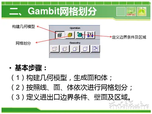
gambit轴流风机网格划分
- 格式:pdf
- 大小:566.64 KB
- 文档页数:37
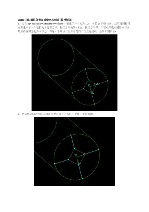
GAMBIT圆/圆柱体得高质量网格划分(钱币划分)1)先在opteration--geometry-volumn中创建了一个高为100,半径15得圆柱体。
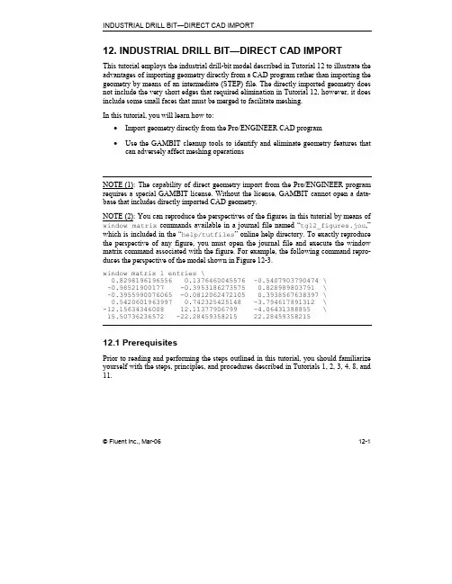
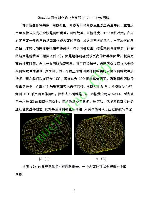
然后再圆柱得底面建立了一个边长为8得正方形,将正方形旋转45度,使正方形得一个顶点跟底面圆得点对齐,然后将圆周分割为4等分,将这4个顶点与正方形得四个顶点连成线,效果如图所示:2)然后用这四条线沿Z轴正向得矢量方向长出4个面,效果如图:3)用正方形去分割底面圆,注意选择connected选项,再用刚才形成得四个面去分割那个古钱形得底面,把它分成4部分,如果做到这一步,基本难得地方就过去了,效果如图所示:4)下面就就是把对应边划分网格,注意正方形每条边对应得圆弧边划分得网格份数就是一样得,效果如图:5)划分面网格,选择map结构得四边形网格,效果如图:6)最后划分体网格,按照cooper方式得六面体网格来划分,效果如图:如何用gambit生成机翼结构网格现在很多新手在用gambit划分网格得时候,习惯性得直接生成体网格,这样做确实简单,但就是简单省力得同时就蕴藏着风险,当遇到复杂外形得时候,就长不了结构网格或者就是生成得网格质量很差,为什么会这样?因为要划分一套高质量得网格,在gambit中直接划分体网格就是不恰当滴。
那如何在gambit中划分结构网格呢?了解pointwise或者icem得同学都知道,这些牛b软件划分网格得思路都就是分区,所以要在gambit中划分结构网格,其基本思路也就是要分区,想偷懒直接划分体网格就是行不通得哦。
下面开始讲课:1、导入实体2、将面移动至中心位置3、在yz平面生成一个圆4、将圆绕着x轴旋转90°5、将圆周split6、生成如图得两条线7、将圆面删除,删除得时候将lower geometry去掉,这样删除之后就还能剩下线8、选择如图中得四条边,生成面9、同上10、查瞧该点得位置,显示其x坐标为15411、选择刚刚生成得两个面,选择copy,并沿着x轴移动15412、同上,复制面到翼端面处,同时沿着z轴调整面,使机翼得控制面位于圆面得中心位置左右13、生成如图所示得线14、生成封闭得面,在gambit中有些面没有生成很难瞧出来,可以将面用阴影来显示查瞧就是否有漏生成面。

INDUSTRIAL DRILL BIT—DIRECT CAD IMPORT© Fluent Inc., Mar-06 12-1 12. INDUSTRIAL DRILL BIT—DIRECT CAD IMPORTThis tutorial employs the industrial drill-bit model described in Tutorial 12 to illustrate the advantages of importing geometry directly from a CAD program rather than importing the geometry by means of an intermediate (STEP) file. The directly imported geometry does not include the very short edges that required elimination in Tutorial 12, however, it does include some small faces that must be merged to facilitate meshing.In this tutorial, you will learn how to:• Import geometry directly from the Pro/ENGINEER CAD program• Use the GAMBIT cleanup tools to identify and eliminate geometry features thatcan adversely affect meshing operationsNOTE (1): The capability of direct geometry import from the Pro/ENGINEER program requires a special GAMBIT license. Without the license, GAMBIT cannot open a data-base that includes directly imported CAD geometry. NOTE (2): You can reproduce the perspectives of the figures in this tutorial by means of window matrix commands available in a journal file named “tg12_figures.jou ,” which is included in the “help/tutfiles ” online help directory. To exactly reproduce the perspective of any figure, you must open the journal file and execute the window matrix command associated with the figure. For example, the following command repro-duces the perspective of the model shown in Figure 12-3.window matrix 1 entries \ 0.8298196196556 0.1376460045576 -0.5407903790474 \ -0.98521900177 -0.3953186273575 0.828989803791 \ -0.3955990076065 -0.0812062472105 0.3938567638397 \ 0.5420601963997 0.742325425148 -3.794617891312 \ -12.156******** 12.11377906799 -4.06431388855 \ 15.50736236572 -22.28459358215 22.2845935821512.1 PrerequisitesPrior to reading and performing the steps outlined in this tutorial, you should familiarize yourself with the steps, principles, and procedures described in Tutorials 1, 2, 3, 4, 8, and 11.Problem Description INDUSTRIAL DRILL BIT—DIRECT CAD IMPORT 12-2 © Fluent Inc., Mar-0612.2 Problem DescriptionFigure 12-1 and Figure 12-2 show the drill-bit configuration to be modeled and meshed in this tutorial. Figure 12-1 shows the full model, including the outer face that circumscribes the internal components. Figure 12-2 shows the internal components, themselves. Themodel shown in these figures is identical to that described in Tutorial 11.Figure 12-1: Industrial drill bit configuration—full modelINDUSTRIAL DRILL BIT—DIRECT CAD IMPORT Problem Description© Fluent Inc., Mar-0612-3Figure 12-2: Industrial drill bit configuration—internal componentsThe goals of this tutorial are:• To directly import the drill-bit geometry from the Pro/ENGINEER CAD program • To use GAMBIT cleanup operations to render the model suitable for meshing• To mesh the model using unstructured, tetrahedral mesh elements the quality ofwhich is controlled by means of size functionsThis tutorial, in conjunction with Tutorial 11, also illustrates the differences between direct CAD geometry import and geometry import by means of STEP data files. Specifically, this tutorial imports the data directly from the Pro/ENGINEER program as a “part” file. Consequently, the imported geometry does not include the very short edges that otherwise complicate meshing (see Tutorial 11).Strategy INDUSTRIAL DRILL BIT—DIRECT CAD IMPORT12.3 StrategyThe general strategy employed in this tutorial is as follows:1)Start the Pro/ENGINEER program.2)Launch GAMBIT from within Pro/ENGINEER.3)Import to GAMBIT a Pro/ENGINEER part file that describes the drill-bitgeometry.4)Use GAMBIT cleanup operations to eliminate a few small faces that wouldotherwise complicate meshing.5)Apply size functions to control mesh quality.6)Mesh the model.The operations involved in items 4–6, above, are nearly identical to those described in Steps 4–6 of Tutorial 11.12-4 © Fluent Inc., Mar-06INDUSTRIAL DRILL BIT—DIRECT CAD IMPORT Procedure12.4 ProcedureStep 1: Start Pro/ENGINEER1.In a terminal window, entergambit -id Drill_Bit_ProE –proe proe_startup_command where proe_startup_command is the system-specific command to start Pro/-ENGINEER.This command starts Pro/ENGINEER and displays the Pro/ENGINEER user interface.!GAMBIT is available only in a 32-bit version; therefore, the Pro/ENGINEER version used for direct CAD import must also be 32-bit.© Fluent Inc., Mar-06 12-5Procedure INDUSTRIAL DRILL BIT—DIRECT CAD IMPORT 12-6 © Fluent Inc., Mar-06Step 2: Start GAMBIT from within Pro/ENGINEER1. Start GAMBIT and make it available as an option on the Pro/ENGINEER main menu.a) Open the Pro/ENGINEER Auxiliary Applications form.Tools → Auxiliary Applications…This command sequence opens the Pro/ENGINEER Auxiliary Applicationsform.i. In the list of available auxiliary applications, select gambit , and click Start .Pro/ENGINEER starts GAMBIT and displays a new option—titled,Gambit —on the Pro/ENGINEER main menu. Pro/ENGINEER alsodisplays the message, “Application ‘gambit’ started successfully,” toindicate the successful launch of the GAMBIT program.ii. Click Close to close the Auxiliary Applications form.INDUSTRIAL DRILL BIT—DIRECT CAD IMPORT Procedure © Fluent Inc., Mar-06 12-7 Step 3: Open the Part File1. Open the Pro/ENGINEER part file.a) Open the Pro/ENGINEER part file that describes the drill bit geometry.File → Open…This command sequence opens the Pro/ENGINEER File Openform.i. In the file list, select drill_bit.prt , and click Open .Pro/ENGINEER opens the part file and displays it in the Pro/ENGINEERGUI graphics window.! You cannot operate on parts or assemblies from within Pro/ENGI-NEER while GAMBIT is running.Procedure INDUSTRIAL DRILL BIT—DIRECT CAD IMPORT Step 4: Display the GAMBIT User Interface1.Display the GAMBIT graphical user interface.a)On the Pro/ENGINEER main menu, start the GAMBIT interface.Gambit → StartPro/ENGINEER replaces its foreground user interface with that of GAMBITand remains operational in the background.It is possible to switch between Pro/ENGINEER and GAMBIT operationwhile GAMBIT is running.•To switch from GAMBIT to Pro/ENGINEER, you must exit GAMBIT by means of the File/Close option on the GAMBIT main menu bar.When you exit GAMBIT in this manner, the GAMBIT window isiconized, and GAMBIT continues to run until you end its executionfrom within Pro/ENGINEER.•To switch from Pro/ENGINEER to GAMBIT, select the Gambit→Start option on the Pro/ENGINEER main menu bar.To ensure that any GAMBIT operations are preserved when switching backand forth between GAMBIT and Pro/ENGINEER, it is advisable to save theGAMBIT database before switching from GAMBIT to Pro/ENGINEERoperation.12-8 © Fluent Inc., Mar-06INDUSTRIAL DRILL BIT—DIRECT CAD IMPORT Procedure Step 5: Select the Solver1.Choose the solver from the main menu bar:Solver → FLUENT 5/6The choice of solver affects the types of options available in the SpecifyBoundary Types form. For some systems, FLUENT 5/6 is the default solver. Thecurrently selected solver is shown at the top of the GAMBIT GUI.© Fluent Inc., Mar-06 12-9Procedure INDUSTRIAL DRILL BIT—DIRECT CAD IMPORT 12-10 © Fluent Inc., Mar-06 Step 6: Import the CAD GeometryIn this step, you will directly import the drill-bit geometry from Pro/ENGINEER . GAMBIT designates the imported geometry as “CAD” geometry, and assigns its components a “c_” prefix—for example, c_face.123.! To import geometry directly from Pro/ENGINEER to GAMBIT , you must have aspecial GAMBIT license. Without the license, GAMBIT cannot open a database that includes directly-imported CAD geometry.1. Select the Import CAD Geometry option from the GAMBIT main menu bar.File → Import → CAD...This command sequence opens the Import CAD Geometryform.a) On the CAD Option option button, select the Pro/ENGINEER (DIRECT) option. b) On the Component option button, select the DRILL_BIT.PRT option.The Component option button includes all part files that are currently open in Pro/ENGINEER .2. On the Import CAD Geometry form, click Accept .GAMBIT imports the part file and displays the geometry shown in Figure 12-3.© Fluent Inc., Mar-0612-11Figure 12-3: Industrial drill bit—directly imported Pro/ENGINEER part fileStep 7: Merge Faces and Edges to Suppress Model Features As a first step in improving the meshing characteristics of the model, you will perform global face and edge merge operations to eliminate many faces that could otherwise adversely affect meshing.1.Perform a global face-merge operation.GEOMETRY →FACE → SPLIT/MERGE/COLLAPSE/SIMPLIFY FACES RThis command sequence opens the Merge Faces form.a)On the Type option subset, select the Virtual (Tolerance) option.b)On the Faces pick-list option button, select All.c)In the Min. Angle text box, input 160.d)Retain the Merge edges option.e)Click Apply to merge the faces.GAMBIT merges the faces as shown in Figure 12-4.12-12 © Fluent Inc., Mar-06© Fluent Inc., Mar-0612-13Figure 12-4: Model after face-merge operationStep 8: Use Cleanup Tools to Check and Clean Up Geometry GAMBIT cleanup tools allow you to identify and eliminate individual model features that can inhibit meshing. In this step, you will use the cleanup tools to check for the existence of very short edges, “holes,” “cracks,” and small faces in the model and to eliminate some of the small faces.1.Identify any short edges in the model that might cause meshing problems.TOOLS →CLEANUP →CLEAN UP SHORT EDGESThis command sequence opens the Clean Up Short Edgesform.When you open any of the cleanup forms, such as the Clean Up Short Edges form, GAMBIT automatically sets the graphics window color mode to display colors based on connectivity rather than topology. In addition, GAMBIT automatically sets the graphics window pivot function to the user-specified pivot mode.12-14 © Fluent Inc., Mar-06a)Click the Default pushbutton located on the right side of the Maximum length textbox.GAMBIT displays the Maximum length of edges to be included in the Items listand populates the Items list with all edges in the Cleanup domain that meet theMaximum length criterion. (In this case, the entire model constitutes theCleanup domain.) By default, the Maximum length value is 10 times greaterthan the arc length of the shortest edge in the Cleanup domain.b)Select the first edge in the Items list.GAMBIT displays the arc length of the selected edge in the Current lengthfield located below the Items list and highlights and zooms in on the selectededge in the graphics window (see Figure 12-5).Figure 12-5: Automatic graphics-window display of the first listed edgeIn this case, the shortest edge in the model is not short enough to adverselyaffect meshing.2.Check for the existence of holes in the model.“Holes” in the model are internal edge loops that do not constitute face boundaries.© Fluent Inc., Mar-06 12-15TOOLS →CLEANUP →CLEAN UP HOLESThis command sequence opens the Clean Up Holesform.a)Click the Update pushbutton located on the right side of the Items list heading.In this case, GAMBIT does not populate the Items list, because no holes existin the model.3.Check for the existence of cracks in the model.For the purposes of the geometry cleanup operations, a “crack” is defined as a geometry consisting of an edge pair that meets the following criteria:•Each edge in the pair serves as a boundary edge for a separate face.•The edges share common endpoint vertices at one or both ends.•The edges are separated along their lengths by a small gap.TOOLS →CLEANUP →CLEAN UP CRACKSThis command sequence opens the Clean Up Cracks form.12-16 © Fluent Inc., Mar-06© Fluent Inc., Mar-0612-17a) Click the Default pushbutton located on the right side of the Maximum angle textbox.GAMBIT displays the default Maximum angle criterion and automatically populates the Items list with all cracks existing in the model. In this case, GAMBIT does not populate the Items list, because no cracks exist in the model.4. Clean up one sharp angle in the model.In this substep, you will use the Clean Up Sharp Angles form to identify and eliminate an edge pair that constitutes a “sharp angle.” For the purposes of the geometry cleanup operations, a sharp angle is defined as an edge pair that meets the following criteria:• The edge pair shares a common endpoint vertex and serves as part of theboundary for an existing face.• One of the edges in the sharp-angle edge pair serves as a commonboundary edge between its bounded face and an adjacent face.• The angle between the edges in the pair (computed at their commonendpoint vertex) is less than a specified angle.TOOLS →CLEANUP →CLEAN UP SHARP ANGLESThis command sequence opens the Clean Up Sharp Anglesform.a)Click the Default pushbutton located on the right side of the Maximum angle textbox.GAMBIT displays the Maximum angle of angles to be included in the Items listand populates the Items list with all face-vertex pairs in the Cleanup domainthat meet the Maximum angle criterion. By default, the Maximum angle value is20.b)Select the first face-vertex pair in the Items list.GAMBIT highlights and zooms in on the geometry that constitutes the sharpangle (see Figure 12-6).12-18 © Fluent Inc., Mar-06Sharp angleFigure 12-6: Geometry constituting a sharp angleThe Clean Up Sharp Angles operation uses a Merge faces procedure toeliminate any sharp angle. In this case, GAMBIT automatically populates theFaces to merge pick list with suggested faces to merge and selects the Chopoption. (For a complete description of the Clean Up Sharp Angles form, see“Clean Up Sharp Angles” in Section 5.4.2 of the GAMBIT Modeling Guide.)c)Click the Apply pushbutton in the vertical array of pushbuttons located to the rightof the Items list.GAMBIT merges the highly angular region of one face with the adjacent faceto eliminate the sharp angle (see Figure 12-7).© Fluent Inc., Mar-06 12-19Merged regionFigure 12-7: Geometry after sharp-angle cleanup operation5.Clean up small faces in the model.In this substep, you will use the Clean Up Small Faces form to identify and eliminate individual small faces that can adversely affect meshing operations.TOOLS →CLEANUP →CLEAN UP SMALL FACESThis command sequence opens the Clean Up Small Faces form.12-20 © Fluent Inc., Mar-06© Fluent Inc., Mar-0612-21a) Click the Default pushbutton located on the right side of the Maximum area textbox.GAMBIT displays the Maximum area of faces to be included in the Items list and populates the Items list with all faces in the Cleanup domain that meet the Maximum area criterion. By default, the Maximum area value is 100 times greater than the area of the smallest face in the Cleanup Domain .Figure 12-6 shows the three smallest faces in the model, all of which lie at the base of the main drill-bit shaft. These three faces correspond to the first three labels listed in the Items list.ACBFigure 12-8: Three smallest faces in the modelb)Select the first face in the Items list.GAMBIT displays the area of the selected face in the Current area fieldlocated below the Items list and highlights the selected face (face A in Figure12-8) in the graphics window.The Clean Up Small Faces form provides two Method options for eliminatingfaces—Collapse face and Merge face. In this case, GAMBIT automaticallyselects the Merge face option and populates the Faces to merge pick list withsuggested faces to merge.c)Click the A/N pushbutton in the vertical array of pushbuttons located to the right ofthe Items list.The A/N (“Apply/Next”) pushbutton removes the currently selected face fromthe model, then updates the Items list and automatically selects the nextsmallest face in the Cleanup domain. In this case, GAMBIT eliminates theselected face and automatically selects the next smallest face (face B in Figure12-8).d)Click A/N again to eliminate the next smallest face in the Cleanup domain.12-22 © Fluent Inc., Mar-06GAMBIT eliminates the selected face and automatically highlights the nextsmallest face (face C in Figure 12-8).e)Click Apply to eliminate the third smallest face in the Cleanup domain.Figure 12-9 shows the geometry in the region of the three smallest faces aftertheir removal from the model.Figure 12-9: Geometry with three smallest faces cleaned upHaving eliminated the three small, ovoid faces at the base of the main shaft,you will now remove four small, rectangular faces that serve as lips to other,larger faces (see Figure 12-10).© Fluent Inc., Mar-06 12-23DE FGFigure 12-10: Small, rectangular lip facesf)Select the first face in the Items list.GAMBIT highlights and zooms in on the smallest of the rectangular lip faces(face D in Figure 12-10) and automatically selects the Merge faces option andpopulates the Faces to merge pick list with suggested faces to merge.g)Click the A/N pushbutton to eliminate the selected face and automatically select thenext smallest face (face E in Figure 12-10).h)Click the A/N pushbutton to eliminate the selected face and automatically select thenext smallest face (face F in Figure 12-10).i)Click the A/N pushbutton to eliminate the selected face and automatically select thenext smallest face (face G in Figure 12-10).j)Click Apply to eliminate the last of the lip faces.After cleanup of the last lip face, the Items list still contains a list of smallfaces; however, the remaining faces are not small enough to adversely affectmeshing operations.Figure 12-11 shows the final, cleaned-up geometry.12-24 © Fluent Inc., Mar-06© Fluent Inc., Mar-0612-25Figure 12-11: Final, cleaned-up model geometryStep 9: Apply Size Functions to Control Mesh Quality Highly skewed elements adversely affect numerical computations for which the mesh is created. GAMBIT includes several features that allow you to control the mesh, one of which is the application of size functions. For example, size functions can be used to specify the rate at which volume mesh elements change in size in proximity to a specified boundary. In this step, you will apply size functions to four faces of the drill-bit geometry and, thereby, control the size of the nearby mesh elements to eliminate the skewed elements.1.Specify a size function and apply it to four faces of the model.TOOLS →SIZE FUNCTIONS →CREATE SIZE FUNCTIONThis command sequence opens the Create Size Function form.a)Retain the Type:Fixed option.(NOTE: In addition to the “fixed” size function illustrated in this tutorial,GAMBIT provides “curvature,” “proximity,” and “meshed” size functions.Curvature and proximity size functions are useful for controlling the mesh inregions of high curvature and small gaps, respectively. Meshed size functionsuse existing meshes to determine the size-function start size. See Section 5.2.2of the GAMBIT Modeling Guide.)12-26 © Fluent Inc., Mar-06b)On the Entities:Source option button, select the Faces option.c)In the Faceslist box, select the four faces shown (shaded) in Figure 12-12.d)On the Entities:Attachment option button, select the Volumes option.e)In the Volumes list box, select the volume.f)In the Start size text box, enter the value 0.035.g)In the Growth rate text box, enter the value, 1.2.h)In the Max. size text box, enter the value, 0.4.i)Click Apply to create the size function.© Fluent Inc., Mar-06 12-27Step 10: Mesh the VolumeAfter the imported geometry is cleaned up and the size-function is created and attached, you can mesh the geometry using an unstructured, tetrahedral mesh.1.Mesh the drill-bit volume.MESH →VOLUME →MESH VOLUMESThis command sequence opens the Mesh Volumesform.a)Activate the Volumes list box.b)Select the volume.GAMBIT automatically selects the Scheme:Elements:Tet/Hybrid and Scheme:Type:TGrid options.c)Retain the automatically selected Scheme options.d)On the Spacing option button, retain the Interval size option.12-28 © Fluent Inc., Mar-06e)In the Spacing text box, retain the default value of 1.(NOTE: The size function you attached to the volume in the previous step willoverride the Spacing specifications.)f)Click Apply.Figure 12-13 shows the final meshed volume.Figure 12-13: Meshed drill-bit volume© Fluent Inc., Mar-06 12-29Step 11: Examine the Volume Mesh1.Select the EXAMINE MESHcommand button at the bottom right of the GlobalControl toolpad.This action opens the Examine Meshform.a)Click Update at the bottom of the Examine Mesh form.12-30 © Fluent Inc., Mar-06GAMBIT does not automatically update the graphics display when you open the Examine Mesh form or modify its specifications, such as Display Type or Quality Type. To update the graphics display, you must click the Update push-button located at the bottom of the form. GAMBIT displays the Update pushbutton label in red lettering whenever the display needs to be updated to reflect the current Examine Mesh specifications.Some Examine Mesh operations automatically update the graphics display.For example, if you select the Display Type:Range option and click one of the histogram bars (see below), GAMBIT automatically updates the display.b)Select Range under Display Type at the top of the form.The 3D Element type selected by default at the top of the form is a brick .You will not see any mesh elements in the graphics window when you first open the Examine Mesh form, because there are no hexahedral elements in the mesh.c)Left-click the tetrahedron icon next to 3D Element near the top of the form.The tetrahedral mesh elements will now be visible in the graphics window.d)Select or retain EquiSize Skew from the Quality Type option menu.e)Left-click the histogram bars that appear at the bottom of the Examine Mesh formto highlight elements in any given quality range.Figure 12-14 shows the graphics window that results for elements withEquiSize Skew values between 0.5 and 0.6.© Fluent Inc., Mar-06 12-3112-32© Fluent Inc., Mar-06Figure 12-14: Elements with EquiSize Skew values between 0.5 and 0.6f) On the Examine Mesh form, click Close to close the form.Step 12: Export the Mesh and Close GAMBIT1.Export a mesh file.a)Open the Export Mesh File formFile → Export → Mesh…This command sequence opens the Export Mesh Fileform.iii.Click Accept.GAMBIT writes the mesh file to your working directory.2.Save the GAMBIT session and close GAMBITa)Select Close from the File menu.File → CloseThis command sequence opens the Closeform.© Fluent Inc., Mar-06 12-33The Close option is available only when GAMBIT is launched from within thePro/ENGINEER program.b)Click Yes to save the current session and return to Pro/ENGINEER.The Pro/ENGINEER user interface redisplays in the foreground, andGAMBIT continues to run in the background.12-34 © Fluent Inc., Mar-06Step 13: Exit Pro/ENGINEER and GAMBIT1.Exit the Pro/ENGINEER program.File → Exit…form.This command sequence opens the Pro/ENGINEER CONFIRMATIONa)Click Yes to exit Pro/ENGINEER.When you exit Pro/ENGINEER, GAMBIT is still running, and the Close formis still open.b)On the GAMBIT Close form, click No to exit GAMBIT.© Fluent Inc., Mar-06 12-3512.5 SummaryThis tutorial demonstrates the direct import of CAD geometry into GAMBIT and the operations that are sometimes required to render such geometry amenable to GAMBIT meshing operations. A comparison of the procedures described here with those of Tutorial 11 illustrates the advantages of direct CAD import versus import of CAD geometry by means of intermediate files—for example, STEP files. Specifically, the directly imported geometry does not include the very short edges that result from geometry import by means of the STEP file.12-36 © Fluent Inc., Mar-06。
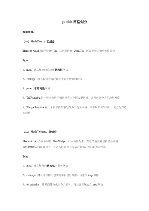
gambit网格划分基本类型:(一)Mesh Face :面划分Element :Quad:四边形网格Tri:三角形网格Quad/Tri:四边形和三角形网格混合Type :1、map:建立规则的四边形结构性网格2、submap:将不规则的区域划分为几个规则的区域3、pave:非结构性网格4、Tri Primitive:将一个三角形区域划分为三个四边形区域,并同时划分为四边形网格5、Wedge Primitive:将一个楔形的尖端划分为三角形网格,沿着楔形向外辐射,划分为四边形网格(二)Mesh Volume:体划分Element :Hex:六面体网格Hex/Wedge:以六面体为主,在适当的位置包括楔形网格Tet/Hybrid:以四面体为主,在适当的位置上包括六面体、锥形和楔形网格Type :1、map:建立规则的结构化六面体网格2、submap:将不可结构化划分的体积进行分割,再建立map网格3、tet primitive:将四面体分成多个六面体,再对各区域建立map网格4、cooper:通过源面对整个体进行网格样式的扫描,适用于逻辑圆柱体5、stairstep:建立规则六面体网格和相应的微小体积来近似原来的几何体形状,椭圆体。
6、tgrid:将网格指定为四面体元素,但是在适当处可能包括六面体、金字塔形和楔形网格划分方法:(一)MESH FACE FORM1、Map Scheme:4*End+N*Side(1)Periodic(周期性) map Scheme: N*Side,针对圆柱面(2)Face(面)Mapple操作方法:(1)打开“Face Vertex form”对话框,选择用圆圈标注的点,将其修改为“S”类型;然后,打开“Mesh Face Form”对话框,划分网格。
或者(2)在“Mesh Face Form”对话框中,直接将schemme(框架)修改为“Map”。
4*End+L*Side+M*End+Corner+N*2*End+Reverse2、Submap:()()修改方法同2:“E ”改成“S ”。
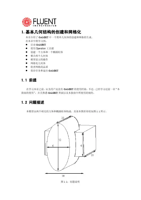
1.基本几何结构的创建和网格化本章介绍了GAMBIT中一个简单几何体的创建和网格的生成。
在本章中将学习到:z启动GAMBITz使用Operation工具箱z创建一个方体和一个椭圆柱体z整合两个几何体z模型显示的操作z网格化几何体z检查网格的品质z保存任务和退出GAMBIT1.1 前提在学习本章之前,认为用户还没有GAMBIT的使用经验,不过,已经学习过前一章“本指南的使用”,并且熟悉GAMBIT界面以及本指南中所使用的规约。
1.2 问题描述本模型由两个相交的方体和椭圆柱体构成,其基本图形形状如图1-1所示。
图1-1:问题说明1.3策略本章介绍使用GAMBIT生成网格的基本操作,特别地,将介绍:z如何使用“top-down”固体建模方法来方便地创建几何体z如何自动生成六面体网格“top-down”方法的意思是用户可以通过生成几何体(如方体、柱体等)来创建几何结构,然后,对它们进行布尔操作(如整合、剪除等),以这种方式,用户不用首先去创建作为基础的点、边和面,就可以快速创建出复杂的几何形体。
一旦创建出一个有效的几何模型,网格就可以直接并且自动地(很多情况下)生成。
在本例子中,将采用Cooper网格化算法来自动生成非结构化的六面体网格。
更复杂的几何结构在生成网格之前可能还需要进行手工分解,这将在后面进行介绍。
本章的学习步骤如下:z创建两个几何体(一个方体和一个椭圆柱体)z整合两个几何体z自动生成网格z检查网格的品质为了使本章的介绍尽量简短,一些必要的步骤被省略了:z调节几何体单边上节点的分布z设置连续介质类型(例如,标识哪些网格区是流体,哪些网格区是固体)和边界类型这些方面的详细内容,也包括其他方面,在随后的章节将涉及到。
1.4步骤输入gambit -id basgeom启动GAMBIT。
这就打开了GAMBIT的图形用户界面(GUI)(图1-2)。
GAMBIT把设定的名称(本例子中为basgeom)作为她将创建的所有文件的词头,如:basgeom.jou。
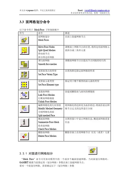

GAMBIT 网格划分第四节体网格划分FEBRUARY 26, 20144.4 体网格划分命令(Volume Meshing Commands)在Mesh/Volume 子面板中有(subpad)以下命令下文描述了以上列出的各命令的功能和操作4.4.1 为体划分网格(Mesh Volumes )Mesh Volumes 命令允许你为一个或多个体创建网格。
当你为一个体划分网格时,GAMBIT 会根据当前设定的参数在整个体中创建网格节点。
要mesh 一个体,需要设定以下参数•待划分网格的体•网格划分方案(Meshing scheme )•网格节点间距(Mesh node spacing )•网格划分选项(Meshing options )指定体(Specifying the Volume)GAMBIT 允许你在网格划分操作中指定任何体,但是,何种网格划分方案(meshing scheme)能应用于这个体,则决定于体的拓扑特性、形状,以及体的面上的顶点的类型。
指定网格划分方案(Specifying the Meshing Scheme)指定网格划分方案需要设定以下两个参数•元素(Elements)•类型(Type)Elements参数用于定义(应用于该体的)体网格元素的形状;Type 参数定义网格划分算法,因此也决定了体中所有网格元素的模式。
下文将介绍上面列出的参数的功能,以及它们对体网格产生的效果。
指定方案元素(Specifying Scheme Elements)GAMBIT 允许你指定下表列出的任何一个体网格Elements(元素)选项以上列出的每个Elements 选项都有一套特定的Type(类型)选项(一个或多个)相对应(见下)指定方案类型(Specifying Scheme Type)GAMBIT 提供以下体网格划分的Type 选项正如上文提到的,每个Elements选项都有一套特定的Type(类型)选项(一个或多个)相对应。
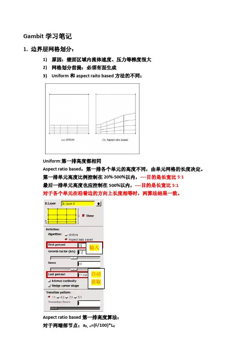
Gambit 学习笔记1. 边界层网格划分:1) 原因:壁面区域内流体速度、压力等梯度很大 2) 网格划分前提:必须有面生成3) Uniform 和aspect raito based 方法的不同:Uniform:第一排高度都相同Aspect ratio based :第一排各个单元的高度不同,由单元网格的长度决定。
第一排单元高度比例控制在20%-500%以内,----目的是长宽比5:1 最后一排单元高度也应控制在500%以内,----目的是长宽比5:1 对于各个单元在沿着边的方向上长度相等时,两算法结果一致。
Aspect ratio based 第一排高度算法: 对于两端部节点:a 0,n =(F/100)*L输入自动获取对于内部节点:a i=i节点两边单元长度和的平均值*比例因子4)Internal Continuity内部连续性:使用区别应该在使用的时候去更好的体会✧壁面边界层印记关系:多个面为壁面时的搭接问题✧网格光滑度和高度自动调整对内部连续性的影响:0/1(0为不起作用,1为起作用)MESH.BLAYER.ANGLE_SMOOTH_FACTORMESH.BLAYER.ADJUST_EDGE_BL_HEIGHT默认值更改方法:edit/default✧内部连续性对网格划分方案type的影响5)边界层楔形角----不能生成✧两条边相交且属于一个面内✧交点类型为corner或reversal型✧每条边单个生成边界层勾选楔形角选项6)边界层第一层高度值确定Y plus理论壁面函数适用于:k-ε型对数定律(Log-law)仅对平衡边界层和充分发展的流动有效,提供了壁面与第一层网格中心可接受间距的上下限,此距离通过无量纲参数y+(≡ρuτy/µ)或y*来表示,当第一层网格位于对数律层内时,y+与y*数值相近,但不同于C1/4µ i.e. ≈0.5.标准和非平衡壁面,每一个近壁面网格中心都应落于Log-law内,30 < y+ < 300,接近于30是最理想的。
G A M B I T软件网格的划分模型的网格划分当用户点击Operation工具框中的Mesh命令按钮时,GAMBIT将打开Mesh 子工具框。
Mesh子工具框包含的命令按钮允许用户对于包括边界层、边、面、体积和组进行网格划分操作。
与每个Mesh子工具框命令设置相关的图标如下。
图标命令设置Boundary LayerEdgeFaceVolumeGroup本章以下部分将详细说明与上面列举的每个命令按钮相关的命令。
3.1 边界层3.1.1 概述边界层确定在与边和/或者面紧邻的区域的网格节点的步长。
它们用于初步控制网格密度从而控制相交区域计算模型中有效信息的数量。
示例作为边界层应用的一个示例,考虑包括一个代表流体流过管内的圆柱的计算模型。
在正常环境下,很可能在紧靠管道壁面的区域内流体速度梯度很大,而靠近管路中心很小。
通过对壁面加入一个边界层,用户可以增大靠近壁面区域的网格密度并减小靠近圆柱中心的网格密度——从而获得表征两个区域的足够的信息而不过分的增大模型中网格节点的总数。
一般参数要确定一个边界层,用户必须设定以下信息:•边界层附着的边或者面•确定边界层方向的面或者体积•第一列网格单元的高度•确定接下来每一列单元高度的扩大因子•确定边界层厚度的总列数用户还可以设定生成过渡边界层——也就是说,边界层的网格节点类型随着每个后续层而变化。
如果用户设定了这样一个边界层,用户必须同时设定以下信息:•边界层过渡类型•过度的列数3.1.2 边界层命令以下命令在Mesh/Boundary Layer子工具框中有效。
图标命令详细说明Create Boundary Layer建立附着于一条边或者一个面上的边界层Modify Boundary Layer更改一个现有边界层的定义Modify Boundary LayerLabel更改边界层标签Summarize BoundaryLayers在图形窗口中显示现有边界层Delete BoundaryLayers删除边界层生成边界层Create Boundary Layer命令允许用户在一条边或者一个面附近定义网格节点步长。
GAMBIT 网格划分第四节体网格划分FEBRUARY 26, 20144.4 体网格划分命令(Volume Meshing Commands)在Mesh/Volume 子面板中有(subpad)以下命令下文描述了以上列出的各命令的功能和操作4.4.1 为体划分网格(Mesh Volumes )Mesh Volumes 命令允许你为一个或多个体创建网格。
当你为一个体划分网格时,GAMBIT 会根据当前设定的参数在整个体中创建网格节点。
要mesh 一个体,需要设定以下参数•待划分网格的体•网格划分方案(Meshing scheme )•网格节点间距(Mesh node spacing )•网格划分选项(Meshing options )指定体(Specifying the Volume)GAMBIT 允许你在网格划分操作中指定任何体,但是,何种网格划分方案(meshing scheme)能应用于这个体,则决定于体的拓扑特性、形状,以及体的面上的顶点的类型。
指定网格划分方案(Specifying the Meshing Scheme)指定网格划分方案需要设定以下两个参数•元素(Elements)•类型(Type)Elements参数用于定义(应用于该体的)体网格元素的形状;Type 参数定义网格划分算法,因此也决定了体中所有网格元素的模式。
下文将介绍上面列出的参数的功能,以及它们对体网格产生的效果。
指定方案元素(Specifying Scheme Elements)GAMBIT 允许你指定下表列出的任何一个体网格Elements(元素)选项以上列出的每个Elements 选项都有一套特定的Type(类型)选项(一个或多个)相对应(见下)指定方案类型(Specifying Scheme Type)GAMBIT 提供以下体网格划分的Type 选项正如上文提到的,每个Elements选项都有一套特定的Type(类型)选项(一个或多个)相对应。
Gambit介绍网格的划分使用Gambit软件,首先要启动Gambit,在Dos下输入Gambit <filemane>,文件名如果已经存在,要加上参数-old。
一.Gambit的操作界面如图1所示,Gambit用户界面可分为7个部分,分别为:菜单栏、视图、命令面板、命令显示窗、命令解释窗、命令输入窗和视图控制面板。
文件栏文件栏位于操作界面的上方,其最常用的功能就是File命令下的New、Open、Save、Save as和Export等命令。
这些命令的使用和一般的软件一样。
Gambit可识别的文件后缀为.dbs,而要将Gambit中建立的网格模型调入Fluent使用,则需要将其输出为.msh文件(file/export)。
视图和视图控制面板Gambit中可显示四个视图,以便于建立三维模型。
同时我们也可以只显示一个视图。
视图的坐标轴由视图控制面板来决定。
图2显示的是视图控制面板。
图2 视图控制面板视图控制面板中的命令可分为两个部分,上面的一排四个图标表示的是四个视图,当激活视图图标时,视图控制面板中下方十个命令才会作用于该视图。
视图控制面板中常用的命令有:全图显示、选择显示视图、选择视图坐标、选择显示项目、渲染方式。
同时,我们还可以使用鼠标来控制视图中的模型显示。
其中按住左键拖曳鼠标可以旋转视图,按住中键拖动鼠标则可以在视图中移动物体,按住右键上下拖动鼠标可以缩放视图中的物体。
命令面板命令面板是Gambit的核心部分,通过命令面板上的命令图标,我们可以完成绝大部分网格划分的工作。
图3显示的就是Gambit的命令面板。
图3 Gambit的命令面板从命令面板中我们就可以看出,网格划分的工作可分为三个步骤:一是建立模型,二是划分网格,三是定义边界。
这三个部分分别对应着Operation区域中的前三个命令按钮Geometry(几何体)、mesh(网格)和Zones(区域)。
Operation中的第四个命令按钮Tools 则是用来定义视图中的坐标系统,一般取默认值。
GAMBIT圆/圆柱体的高质量网格划分(钱币划分)1)先在opteration--geometry-volumn中创建了一个高为100,半径15的圆柱体。
然后再圆柱的底面建立了一个边长为8的正方形,将正方形旋转45度,使正方形的一个顶点跟底面圆的点对齐,然后将圆周分割为4等分,将这4个顶点和正方形的四个顶点连成线,效果如图所示:2)然后用这四条线沿Z轴正向的矢量方向长出4个面,效果如图:3)用正方形去分割底面圆,注意选择connected选项,再用刚才形成的四个面去分割那个古钱形的底面,把它分成4部分,如果做到这一步,基本难的地方就过去了,效果如图所示:4)下面就是把对应边划分网格,注意正方形每条边对应的圆弧边划分的网格份数是一样的,效果如图:5)划分面网格,选择map结构的四边形网格,效果如图:6)最后划分体网格,按照cooper方式的六面体网格来划分,效果如图:如何用gambit生成机翼结构网格现在很多新手在用gambit划分网格的时候,习惯性的直接生成体网格,这样做确实简单,但是简单省力的同时就蕴藏着风险,当遇到复杂外形的时候,就长不了结构网格或者是生成的网格质量很差,为什么会这样?因为要划分一套高质量的网格,在gambit中直接划分体网格是不恰当滴。
那如何在gambit中划分结构网格呢?了解pointwise或者icem的同学都知道,这些牛b软件划分网格的思路都是分区,所以要在gambit中划分结构网格,其基本思路也是要分区,想偷懒直接划分体网格是行不通的哦。
下面开始讲课:1.导入实体2.将面移动至中心位置3.在yz平面生成一个圆4.将圆绕着x轴旋转90°5.将圆周split6.生成如图的两条线7.将圆面删除,删除的时候将lower geometry去掉,这样删除之后就还能剩下线8.选择如图中的四条边,生成面9.同上10.查看该点的位置,显示其x坐标为15411.选择刚刚生成的两个面,选择copy,并沿着x轴移动15412.同上,复制面到翼端面处,同时沿着z轴调整面,使机翼的控制面位于圆面的中心位置左右13.生成如图所示的线14.生成封闭的面,在gambit中有些面没有生成很难看出来,可以将面用阴影来显示查看是否有漏生成面。
gambit网格划分祥解Gambit 介绍网格的划分使用 Gambit 软件,首先要启动 Gambit ,在Dos 下输入Gambit <>,文件名如果已经存在,要加上参数-old 。
一.Gambit 的操作界面如图1所示,Gambit 用户界面可分为7个部分,分别为:菜单栏、视图、命令面板、命令显示窗、命令解释窗、命令输入窗和视图控制面板。
文件栏文件栏位于操作界面的上方,其最常用的功能就是File 命令下的New 、Open 、Save 、Save as 和Export 等命令。
这些命令的使用和一般的软件一样。
Gambit 可识别的文件后缀为.dbs ,而要将Gambit 中建立的网格模型调入Flue nt 使用,则需要将其输出为.msh 文件()。
视图和视图控制面板Gambit 中可显示四个视图,以便于建立三维模型。
同时我们也可以只显示一个视图。
视图的坐标轴由视图控制面板来决定。
图2显示的是视图控制面板。
GrH|)hics [(joratrolActive £ |出|田|田|剛|视图控制面板中的命令可分为两个部分,上面的一排四个图标表示的是四个视图,当激活视图图标时,视图控制面板中下方十个命令才会作用于该视图。
视图控制面板中常用的命令有:渲染方式。
同时,我们还可以使用鼠标来控制视图中的模型显示。
其中按住左键拖曳鼠标可以旋转视图,按住中键拖动鼠标则可以在视图中移动物体,按住右键上下拖动鼠标可以缩放视图中的物体。
命令面板命令面板是Gambit 的核心部分,通过命令面板上的命令图标,我们可以完成绝大部分网格划分的工作。
图3显示的就是Gambit 的命令面板。
选择显示视图、选择视图坐标、选择显示项目、图2视图控制面板全图显51 禅>e ration」團剖Geometry二」口ffil戸21r oluma务Id |诱|图3 Gambit的命令面板从命令面板中我们就可以看出,网格划分的工作可分为三个步骤:一是建立模型,二是划分网格,三是定义边界。
BASIC TURBO MODEL WITH UNSTRUCTURED MESH8. BASIC TURBO MODEL WITH UNSTRUCTURED MESH This tutorial employs a simple turbine blade configuration to illustrate the basic turbo modeling functionality available in GAMBIT. It illustrates the steps and procedures required for importing data that describes the turbo blade, creating a geometric model that describes the flow region surrounding the blade, meshing the model, and exporting the mesh. The example presented here uses 3-D boundary layers to control the shape of the mesh in the regions immediately adjacent to the blade and employs an unstructured hexa-hedral mesh.In this tutorial, you will learn how to:•Import a turbo data file•Create a turbo profile•Modify a turbo profile to affect the shape of a turbo volume•Create a turbo volume•Define turbo zones•Apply 3-D boundary layers to a turbo volume•Mesh a turbo volume•View a turbo volume mesh using both 3-D and 2-D perspectives•Export a turbo volume mesh8.1 PrerequisitesPrior to reading and performing the steps outlined in this tutorial, you should familiarize yourself with the steps, principles, and procedures described in Tutorials 1, 2, 3, and 4.© Fluent Inc., Mar-06 8-1Problem Description BASIC TURBO MODEL WITH UNSTRUCTURED MESH8-2 © Fluent Inc., Mar-068.2 Problem DescriptionFigure 8-1 shows the turbomachinery configuration to be modeled and meshed in this tutorial. The configuration consists of a turbine rotor on which are affixed 60 identical blades, each of which is spaced equidistant from the others on the rotor hub. Each blade includes a concave (pressure ) side and a convex (suction ) side, and the rotor rotates counterclockwise about the x -axis, extracting work from the fluid (air) as it flows betweenthe blades (see Figure 8-2).Figure 8-1: 60-blade turbine rotorBASIC TURBO MODEL WITH UNSTRUCTURED MESH Problem DescriptionOutlet flowInlet flowFigure 8-2: Turbine rotor blade configurationsThe overall goal of this tutorial is to create a geometric model of the flow region immedi-ately surrounding one of the turbo blades and to mesh the model using an unstructured hexahedral mesh.© Fluent Inc., Mar-06 8-3Strategy BASIC TURBO MODEL WITH UNSTRUCTURED MESH8.3 StrategyIn general, the GAMBIT turbo modeling procedure includes seven basic steps:1)Creating or importing edge data that describes the turbo profile2)Creating the turbo profile3)Creating the turbo volume4)Assigning zone types to regions of the turbo volume5)Decomposing the turbo volume6)Meshing the turbo volume7)Viewing the turbo volumeThis tutorial illustrates six of the seven steps listed above. The tutorial excludes the turbo decomposition step, because the turbo volume is to be meshed using unstructured hexahe-dral mesh elements. Turbo volume decomposition is primarily used to facilitate the crea-tion of structured meshes (see Tutorial 9 in this guide).NOTE: In this tutorial, the turbo-volume viewing operation (Step 7, above) is illustrated in conjunction with the mesh examination step (see “Step 11:Examine the Mesh,” below). 8-4 © Fluent Inc., Mar-06BASIC TURBO MODEL WITH UNSTRUCTURED MESH Procedure 8.4 Procedure1.Copy the filepath/Fluent.Inc/gambit2.x/help/tutfiles/turbo_basic.tur (where 2.x is the GAMBIT version number) from the GAMBIT installation area in the directory path to your working directory.2.Start GAMBIT using the session identifier “Basic_Turbo”.Step 1: Select a Solver1.Choose the solver from the main menu bar:Solver → FLUENT 5/6The choice of solver affects the types of options available in the Specify Boundary Types form (see “Step 12:Specify Zone Types,” below). For some systems, FLUENT 5/6 is the default solver. The currently selected solver is shown at the top of the GAMBIT GUI.© Fluent Inc., Mar-06 8-5Procedure BASIC TURBO MODEL WITH UNSTRUCTURED MESH 8-6 © Fluent Inc., Mar-06Step 2: Import a Turbo Data FileTurbo data files contain information that GAMBIT uses to define the turbo profile (see “Step 3:Create the Turbo Profile,” below). Such information includes: point data that describes the shapes of the profile edges, edge-continuity data, and specification of the rotational axis for the turbo volume.1. Select the Import Turbo File option from the main menu bar.File → Import → Turbo...This command sequence opens the Import Turbo Fileform.2. Click the Browse... button.This action opens the Select Fileform.BASIC TURBO MODEL WITH UNSTRUCTURED MESH Procedurea)In the Files list, select turbo_basic.tur.b)On the Select File form, click Accept.3.On the Import Turbo File form, click Accept.GAMBIT reads the information contained in the data file and constructs the set of edges shown in Figure 8-3. The two straight edges shown in the figure describe the hub and casing for the turbo volume. The two sets of curved edges constitute cross sections of a single turbo blade.Casing edgeBlade cross sectionsHub edgeFigure 8-3: Imported turbo geometry© Fluent Inc., Mar-06 8-7Procedure BASIC TURBO MODEL WITH UNSTRUCTURED MESH 8-8 © Fluent Inc., Mar-06Step 3: Create the Turbo ProfileThe turbo profile defines the basic characteristics of the turbo volume, including the shapes of the hub, casing, and periodic (side) surfaces. In GAMBIT , the edges that describe the hub, casing, and blade cross sections are defined by means of their inlet endpoint vertices.1. Specify the hub, casing, and blade-cross-section edges of the turbo profile.TOOLS →TURBO →CREATE PROFILEThis command sequence opens the Create Turbo Profileform.In this step, you will specify vertices that define the hub, casing, and blade cross-sections. In addition, you will specify the axis of revolution for the turbo configu-ration. All instructions listed in this step refer to the vertex labels shown in Figure 8-4.BASIC TURBO MODEL WITH UNSTRUCTURED MESH Procedure© Fluent Inc., Mar-06 8-9 Hub InletCasing InletAB CDBlade TipsFigure 8-4: Vertices used to specify the turbo profilea) Activate the Hub Inlet list box on the Create Turbo Profile form.To activate an input field, such as a list box, on any GAMBIT specification form, left -click in the input box located adjacent to the field label—in this case, “Hub Inlet ”. (By default, GAMBIT activates the Hub Inlet field when you open the Create Turbo Profile form.)b) Select vertex A .c) Activate the Casing Inlet list box.d) Select vertex B .e) Specify the x axis as the axis of revolution for the turbo configuration.i. Click the Axis:Define pushbutton.This action opens the Vector Definition form.Procedure BASIC TURBO MODEL WITH UNSTRUCTURED MESH8-10© Fluent Inc., Mar-06 ii.Select the Direction:X-Positive option.iii.On the Vector Definition form, click Apply.f)Activate the Blade Tips list box.g)Select vertex C.h)Select vertex D.!The order in which the Blade Tips vertices are selected is important to the definition of a turbo profile. Specifically, the Blade Tips vertices must be selected in order from the hub cross section to the casing cross section.i)Click Apply to accept the vertex selections and create the turbo profile.GAMBIT creates the turbo profile shown in Figure 8-5.Rail edgesRail edges Medial edgesABFigure 8-5: Turbo profileThe profile includes six new edges, four of which are real edges and two of which are virtual edges. The four real edges are circular arc (“rail”) edges that are formed by revolving the hub and casing endpoint vertices about the axis of revo-lution for the profile. The two virtual edges are “medial” edges, the centermost shapes of which represent the mean shapes of the blade cross sections. The end-point vertices of the medial edges are hosted by the rail edges, and the medial edges are defined such that they pass through the leading and trailing vertices of the blade cross sections. The medial edges define the shapes of the periodic sur-faces on the turbo volume (see “Step 5:Create the Turbo Volume,” below).© Fluent Inc., Mar-06 8-11Step 4: Modify the Inlet and Outlet Vertex Locations It is often useful to control the shape of the turbo volume such that its inlet and outlet surfaces represent smooth flow transitions to and from the inlet and outlet ends, respectively, of the turbo blade. In GAMBIT, you can control the shape of the turbo volume by adjusting the positions of the medial-edge endpoint vertices prior to con-structing the volume.1.Open the Slide Virtual Vertex form.TOOLS →TURBO →SLIDE VIRTUAL VERTEXThis command sequence opens the Slide Virtual Vertexform.a)Select the inlet endpoint vertex of the medial edge for the casing blade crosssection (vertex A in Figure 8-5, above).b)In the U Value field, enter the value 0.999.As an alternative to entering a value in the U Value field, you can select thevertex in the graphics window and drag it along its host rail edge until the UValue field value is 0.999.c)Retain the Move With Links (default) option.8-12 © Fluent Inc., Mar-06© Fluent Inc., Mar-06 8-13 The Move With Links option specifies that GAMBIT is to apply the current Slide Virtual Vertex specifications to all medial-edge inlet endpoint vertices in addi-tion to the selected vertex.d) Click Apply to accept the new position of the medial-edge inlet endpoint vertices. e) Select the outlet endpoint vertex of the medial edge for the casing blade crosssection (vertex B ).f) In the U Value field, enter the value 0.019.g) Retain the Move With Links (default ) option.h) Click Apply to accept the new position of the medial-edge outlet endpoint vertices.The modified turbo profile appears as shown in Figure 8-6.Figure 8-6: Turbo profile with modified inlet and outlet vertex locationsStep 5: Create the Turbo VolumeA “turbo volume” is a 3-D region—which is defined by a set of one or more geomet-ric volumes—that represents the flow environment surrounding the turbo blade. The turbo volume characteristics are determined by the turbo profile and by specification of the number of blades on the rotor (or angle between blades), the tip clearance, and the number of spanwise sections. This example does not include a tip clearance but does include spanwise sectioning.1.Specify the pitch and number of spanwise sections for the turbo volume.TOOLS →TURBO →CREATE TURBO VOLUMEThis command sequence opens the Create Turbo Volumeform.a)In the Pitch text box, enter 60.b)On the Pitch option button (located to the right of the Pitch text box), select theBlade count option.c)In the Spanwise Sections text box, enter 2.d)Click Apply.GAMBIT creates the turbo volume shown in Figure 8-7.8-14 © Fluent Inc., Mar-06© Fluent Inc., Mar-06 8-15 Casing faceHub faceInletfaces OutletfacesFigure 8-7: Turbo volume—consisting of two geometric volumesStep 6: Define the Turbo ZonesThis step standard zone types to surfaces of the turbo volume. The zone-type specifi-cations determine which faces are linked for meshing. In addition, GAMBIT auto-matically associates turbo zone types to boundary zone definitions for some solvers.1.Specify the faces that constitute the hub, casing, inlet, outlet of the turbo volume, aswell as the pressure and suction sides of the turbo blade.TOOLS →TURBO →DEFINE TURBO ZONESThis command sequence opens the Define Turbo Zonesform.a)Activate the Hub list box.b)Select the bottom (hub) face of the turbo volume (see Figure 8-7, above).c)Activate the Casing list box.d)Select the top (casing) face of the turbo volume.e)Activate the Inlet list box.f)Select the two inlet faces.g)Activate the Outlet list box.h)Select the two outlet faces.8-16 © Fluent Inc., Mar-06i)Activate the Pressure list box.j)Select the six faces on the inner-curve (pressure side) of the turbo blade.k)Activate the Suction list box.l)Select the six faces on the outer-curve (suction side) of the turbo blade.m)Click Apply to assign the turbo zone types.© Fluent Inc., Mar-06 8-17Step 7: Apply 3-D Boundary LayersFor turbo models, 3-D boundary layers allow you to ensure the creation of high-quality mesh elements in regions adjacent to the turbo blade surfaces. Such boundary layers are particularly useful when the turbo volume is to be meshed using an unstructured meshing scheme.1.Specify the hub, casing, and blade-cross-section edges of the turbo profile.TOOLS →TURBO →CREATE/MODIFY BOUNDARY LAYERSThis command sequence opens the Create Boundary Layerform.8-18 © Fluent Inc., Mar-06© Fluent Inc., Mar-06 8-19 a) In the First row text box, enter a value of 1.b) In the Growth factor text box, enter a value of 1.2.c) In the Rows text box, specify a value of 5, either by direct input of the value or bysliding the Rows slider bar.GAMBIT automatically calculates a Depth value of 7.4416, based on the First row , Growth factor , and Rows specifications.d) Select the Internal continuity option.e) In the Attachment input field, select the Faces option.f) Activate the Faces list box, and select the 12 faces that comprise the pressure andsuction sides of the turbo blade.g) Click Apply .Figure 8-8 shows the 3-D boundary layers projected onto the three spanwisesurfaces of the turbo volume.Figure 8-8: Turbo volume with 3-D boundary layersBy default, GAMBIT displays the boundary layers in the graphics window unless they are made invisible by direct user action. The boundary layer dis-play can make it difficult to view the model during subsequent steps in the modeling process; therefore, it is advisable to render the boundary layers invisible before continuing the tutorial.2.Select the SPECIFY DISPLAY ATTRIBUTEScommand button on the GlobalControl toolpad.This action opens the Specify Display Attributesform.a)Select the B. Layers check box.b)Select the Visible:Off option.c)Click Apply.8-20 © Fluent Inc., Mar-06GAMBIT turns off the display of the boundary layers.d)Close the Specify Display Attributes form.© Fluent Inc., Mar-06 8-21Step 8: Mesh the Blade Cross-Section EdgesIn this step, you will pre-mesh the edges that represent the blade cross sections, thereby ensuring a finer mesh in proximity to the turbo blade surfaces than is created in the bulk of the turbo volume.1.Mesh the centermost pressure-side edges of the turbo blade.TOOLS →TURBO →MESH EDGES/FACES/VOLUMESThis command sequence opens the Mesh Edgesform.a)Activate the Edges list box, and select the three centermost edges on the pressureside of the blade cross sections.b)On the Grading:Type option button, retain Successive Ratio.8-22 © Fluent Inc., Mar-06© Fluent Inc., Mar-06 8-23 c) In the Ratio input field, enter a value of 1.02.d) Select the Double sided option.When you select the Double sided option, GAMBIT changes the Ratio input field to Ratio 1 and displays a field named Ratio 2 that contains a ratio specifi-cation identical to that of Ratio 1 (that is, 1.02).e) On the Spacing option button, select Interval count .f) In the Spacing text box, enter a value of 100.g) Click Apply .GAMBIT meshes the selected edges as shown in Figure 8-9. The Double sided option with a ratio of 1.02 grades the edges such that mesh nodes are bunchednear the endpoint vertices of the edges.Figure 8-9: Meshed centermost pressure-side edges of the turbo blade2. Mesh the suction-side edges of the turbo blade.a) Activate the Edges list box, and select the three centermost edges on the suctionside of the blade cross sections.b) On the Grading:Type option button, retain Successive Ratio .c)In the Ratio input field, enter a value of 1.02.d)Select the Double sided option.e)On the Spacing option button, retain Interval count.f)In the Spacing text box, enter a value of 110.g)Click Apply.3.Mesh the leading edges of the turbo blade.a)Activate the Edges list box.b)Select the six edges (two edges on each cross section) on either side of the leadingvertices for the top, middle, and bottom blade cross sections.!When selecting the edges, modify the edge senses, as necessary, such that they point away from the leading vertices of the cross sections. When youselect an edge in the graphics window, GAMBIT automatically displays anarrowhead in the middle of the edge to indicate the sense of the edge. Tochange the sense of any selected edge, Shift-middle-click the edge. (NOTE: Ifthe sense-direction arrowhead is obscured by mesh nodes displayed on theedge, set the Interval count to 1 while selecting edges for meshing.)c)On the Grading:Type option button, retain Successive Ratio.d)In the Ratio input field, enter a value of 1.05.The single-sided meshing option with a ratio of 1.05 grades the edges suchthat mesh nodes are bunched near the leading vertices of the edges—that is, inthe regions of highest curvature for the edges.e)On the Spacing option button, retain Interval count.f)In the Spacing text box, enter a value of 15.g)Click Apply.4.Mesh the trailing edges of the turbo blade.a)Activate the Edges list box.b)Select the six edges (two edges on each cross section) on either side of the trailingvertices for the three blade cross sections.8-24 © Fluent Inc., Mar-06© Fluent Inc., Mar-06 8-25 c) On the Grading:Type option button, retain Successive Ratio .d) In the Ratio input field, enter a value of 1.e) On the Spacing option button, retain Interval count .f) In the Spacing text box, enter a value of 3.g) Click Apply .Figure 8-10 shows the final edge-mesh configuration for the turbo blade crosssections.Figure 8-10: Meshed edges of turbo blade cross sectionsStep 9: Mesh the Center Spanwise FaceTo create an unstructured mesh for this example, it is best to pre-mesh the middle spanwise face and to employ the middle face as a source face for a Cooper meshing scheme applied to the two geometric volumes. The use of the middle face as a source face ensures that the Cooper scheme produces a mesh with minimal distortion throughout the turbo volume.1.Mesh the center spanwise face of the turbo volume.TOOLS →TURBO →MESH EDGES/FACES/VOLUMES RThis command sequence opens the Mesh Faces form.a)Activate the Faces list box, and select the middle spanwise face.GAMBIT automatically selects the Quad and Pave Scheme options based onthe face characteristics.8-26 © Fluent Inc., Mar-06© Fluent Inc., Mar-06 8-27 b) On the Scheme:Elements option button, retain the Quad option.c) On the Scheme:Type option button, retain the Pave option.d) On the Spacing option button, select the Interval size option.e) In the Spacing text box, enter a value of 5.f) Click Apply .GAMBITmeshes the middle spanwise face as shown in Figure 8-11.Figure 8-11: Meshed center spanwise faceStep 10: Mesh the VolumesIn this step, you will apply a Cooper meshing scheme to the two geometric volumes that comprise the turbo volume.1.Mesh the turbo volume.TOOLS →TURBO →MESH EDGES/FACES/VOLUMES RThis command sequence opens the Mesh Volumes form.a)Activate the Volumes list box, and select the both of the geometric volumes thatcomprise the turbo volume.GAMBIT automatically selects the Scheme:Elements:Hex/Wedge and Scheme:Type:Cooper options for the selected volumes.b)Retain the automatically selected Scheme options.c)On the Spacing option button, select Interval size.8-28 © Fluent Inc., Mar-06© Fluent Inc., Mar-06 8-29 d) In the Spacing text box, enter a value of 10.e) Click Apply .GAMBITmeshes the volumes as shown in Figure 8-12.Figure 8-12: Meshed volumesStep 11: Examine the Mesh1.Select the EXAMINE MESHcommand button at the bottom right of the GlobalControl toolpad.This action opens the Examine Meshform.The Examine Mesh form allows you to view various mesh characteristics for the 3-D mesh. For example, Figure 8-13 displays volume mesh elements for which the EquiSize Skew parameter is between 0.4 and 0.5 for this example.a)Click Update at the bottom of the Examine Mesh form.8-30 © Fluent Inc., Mar-06© Fluent Inc., Mar-06 8-31 GAMBIT does not automatically update the graphics display when you open the Examine Mesh form or modify its specifications, such as Display Type or Quality Type . To update the graphics display, you must click the Update push-button located at the bottom of the form. GAMBIT displays the Update pushbutton label in red lettering whenever the display needs to be updated to reflect the current Examine Mesh specifications.Some Examine Mesh operations automatically update the graphics display. For example, if you select the Display Type:Range option and click one of the histogram bars, GAMBITautomatically updates the display.Figure 8-13: Hexahedral mesh elements—EquiSize Skew = 0.4–0.5The Examine Mesh command and options can be used in conjunction with the View Turbo Volume command to view 2-D characteristics of the mesh on the hub, casing, and spanwise surfaces. Such views are particularly useful when examining the mesh on highly twisted blades.2. Display the middle spanwise surface in a cascade turbo view.TOOLS →TURBO →VIEW TURBO VOLUMEThis command sequence opens the View Turbo Volume form.8-32© Fluent Inc., Mar-06a) Select the Cascade surface:Spanwise option.b) In the Spanwise text box, enter a value of 1.The Cascade surface specifications described above specify a flattened, 2-D display of the middle spanwise surface of the turbo volume.c) Click Apply .Figure 8-14 displays face mesh elements for which the EquiSize Skew parameter is between 0.1 and 0.3 for this example. (NOTE: To view the 2-D face elements shown in Figure 8-14, select the Display Type:2D Element option on the Examine Mesh form, and specify the display of quadrilateral () elements.)© Fluent Inc., Mar-068-33Figure 8-14: Quadrilateral mesh elements—EquiSize Skew = 0.1–0.3Figure 8-15 displays a zoomed view of the mesh in the region surrounding theblade tip.Figure 8-15: Quadrilateral mesh elements—zoomed view near blade tipd)Select the Off option and click Apply to turn off the cascade turbo view beforespecifying zone types.8-34 © Fluent Inc., Mar-06Step 12: Specify Zone TypesYou can use the Specify Boundary Types command to apply solver-specific boundary zone specifications to surfaces of the turbo volume. For some solver options, includ-ing Fluent 5/6, GAMBIT automatically assigns such boundary zone specifications. 1.Check the automatically applied boundary zone types.ZONES →SPECIFY BOUNDARY TYPESThis command sequence opens the Specify Boundary Typesform.© Fluent Inc., Mar-06 8-35Step 13: Export the Mesh and Exit GAMBIT1.Export a mesh file.a)Open the Export Mesh File form.File → Export → Mesh…form.This command sequence opens the Export Mesh Filei.Enter the File Name for the file to be exported—for example, the file name“basic_turbo.msh”.ii.Click Accept.GAMBIT writes the mesh file to your working directory.2.Save the GAMBIT session and exit GAMBIT.a)Select Exit from the File menu.File → Exitform.This action opens the Exitb)Click Yes to save the current session and exit GAMBIT.8-36 © Fluent Inc., Mar-068.5 SummaryThis tutorial demonstrates the use of the basic turbo modeling operations available in GAMBIT. The edge data that describes the geometry of the turbo profile was imported from a turbo data file, and the completed turbo profile was adjusted to affect the shape of the turbo volume. The turbo volume was divided into two spanwise sections, each of which was meshed by means of a Cooper scheme that employed the common face between them as a source face. Three-dimensional boundary layers were applied to the surfaces of the turbo blade to ensure a high-quality mesh in proximity to the turbo blade. Finally, the mesh examining capabilities in GAMBIT were used in conjunction with the turbo viewing capability to examine the 2-D mesh on the middle spanwise face.© Fluent Inc., Mar-06 8-37。