Experimental drag reduction study of super-hydrophobic surface with dual-scale
- 格式:pdf
- 大小:2.51 MB
- 文档页数:6
立项报告1、项目简介水下超空泡射弹是一种新型水下武器,在功能上与脱壳穿甲弹相似,依靠弹道末端高的动能存量打击目标。
超空泡射弹的工作介质是水,而物体在水中所受到的阻力约为在空气中的1000倍,用常规方法明显提高水下航行体速度要受到很大的限制。
一段时间以来,研究人员尝试了各种减阻的方法,如边界层抽吸减阻等,但减阻效果通常都不理想。
超空泡减阻技术是一种可以使水下高速运动航行体获得90%减阻量的革命性减阻方法,基于这种新概念、新原理研制的水下超空泡射弹,可以突破普通射弹水下运动极限,使水下射弹的速度提高到1000m/s的量级,大大增加射弹的行程和杀伤力,提高进攻和防御能力。
射弹在水中高速运动时,贴近其表面的液体压力就会降低,当射弹的速度增加到某一临界值时,流体的压力将等于其饱和蒸汽压力,此时流体就会发生相变,由液相变为汽相,这就是空化现象。
随着航行体速度的不断增加,空泡沿着航行体表面不断后移、扩大、发展进而形成超空泡。
它的形成使液体对物体表面的浸湿面积减少,从而大大降低了粘性阻力,达到减阻的效果。
本项目拟通过对已有的射弹结构进行动力特性和流体动力分析,并综合考虑阻力系数、升力系数等各种水动力系数以及应用情况来最终优化结构设计,进一步减小射弹运动时受到的阻力、提高其运动时的稳定性。
2、申请理由本试验小组四人,均来自航天学院飞行器设计与工程专业,在中学时都受过专门的数学竞赛培训,拥有扎实的数学功底和娴熟的研究技能。
通过一年的大学学习,我们熟练掌握了高等数学和线性代数这两项研究中基础性的工具以及必要的工程制图知识,学会了查阅文献的基本方法。
在导师魏英杰教授的指导下,我们查阅了相关的文献,对本课题已经具有了充分的了解和认识。
在与学长们的交流中,我们接触并自学了Matlab、AutoCAD等工具软件。
在接下来的暑假中,我们计划自学相关的专业知识如流体力学和结构动力学等,并自学相关的力学分析软件如Fluent,为接下来的设计优化工作打好基础。
螺旋桨瞬态流场数值模拟周文松【摘要】建立完善的螺旋桨绕流理论异常困难,这一方面是由于螺旋桨流场整体旋转性、非定常非线性、三维效应、气流粘性、涡桨干扰等原因;另一方面是螺旋桨流场的流场结构有待于进一步认知。
文章采用CFD方法对螺旋桨的瞬态流场结构进行了重点研究,详细绘制了自启动瞬间直至充分发展的螺旋桨瞬态流场结构图及所受气动力的变化图,分析了流场变化特性及其对升力的影响。
%The establishment of a perfect theory for the propeller flow field has been a hard job up to now. Firstly, the pro-peller flow field has many complicated characters such as the entire rotation, the unsteady and nonlinear characters, the 3-D effects, the interference between the vortex and the propeller, and so on. S econd, the structure of the flow field hasn ’t been well known. In this paper, the aerodynamic performance of the instantaneous propeller flow field was studied. The de-tailed flow field structures and the evolution of the aerodynamic forces were drawn. The characters of the flow field and its effects on lift and moment were analyzed.【期刊名称】《海军航空工程学院学报》【年(卷),期】2014(000)003【总页数】5页(P247-251)【关键词】螺旋桨;瞬态流场;数值模拟【作者】周文松【作者单位】海军航空工程学院训练部,山东烟台264001【正文语种】中文【中图分类】V211.44螺旋桨在军用和民用上有着广泛的应用。
英语推荐信范文及翻译英语推荐信英语推荐信英语推荐信英语推荐信篇 1 Dear Colleagues: MS. XXX requested a letter of reference from me to support her application for graduate studies at your university. As her research adviser when she was a graduate student in my school of science Beijing University of Chemical Technology, I am pleased to comply with her request. I have known Ms. Zhang since 2003, when she was admitted as a Master of Science candidate into the school. As her research adviser, I directed her research and found her a promising youth radiating with intelligence and creativity. During her first year, she got a very good record in major courses and earned good scores major and general GPA 3.3. She particularly enjoyed challenging areas of studies such as Quantum Chemistry and Theory of Electrochemistry. During the following two years, Ms. Zhang worked on a computational theory study of inorganic functional materials project for his degree thesis “Theoretical Study of Electronic Structures of Several Representative Metal Element in the Hydrotalcite Slabs”. To make the theory model meet the actual materials, she faced down many practical problems, such as building reasonable module of inorganic materials, and calculation techniques. Working hard and independently, she cracked the problems one by one, and came up with a thesis that was characterized by academic excellence. During her M.S. period, she had three papers published in international journals. Judging by her outstanding performance while she studied with me, I am convinced that Ms. Zhang has acquired the knowledge and intellectualsophistication on the basis of which she can undertake world-class training. I therefore lend her my enthusiastic support and would appreciate your favorable consideration of her application. From: x x x x Department of the ***** CLASS GIFTED for YOUTHS University of Science and Technology Hefei, Anhui *****, P.R. China July 1, 1998 英语推荐信篇2 Dear Sir or x x x:I take great pleasure in recommending Ren Ren, one of my favorite students, for admission into your distinguished graduate program. Mr. Ren was admitted in 1986 at 14 years of age into the ***** CLASS for the GIFTED YOUTHS, my university“s unique program that caters to the intellectual needs of unusually talented Chinese youngsters. It was a rare privilege he earned with his nearly impeccable academic performance through the years of his elementary and secondary school. He impressed me almost as he entered into my university, a major cradle of China“s scientific and technological talents. At the time, members of the Gifted Class all had to spend half a month studying by themselves the principles of calculus and then take an exam so that we could evaluate their self-study capability. Mr. Ren scored the highest grade in that exam. He also exhibited a keenly whetted mind during class discussions. To my regret at the time, his English was not as good as his mathematics or physics. But I noticed he made a point of working especially hard in improving his English during his five undergraduate years with us. By now, he seems to be at least as proficient in English as most of his former classmates in the Gifted Class. In my experience with Mr. Ren, I was impressed with not only his extraordinary intelligence but also his ambitions and persistence. I am sure that Mr. Ren will be an outstanding student in any doctoral program that he may care to enroll in. So I would like to support him firmly in his quest recommendation into account when considering his application. Iwould greatly appreciate it you decide to accept him as he wishes. Yours sincerely x x x x Professor and Deputy Head 英语推荐信篇3 Dear Admissions Committee, As Director of the State Key Laboratory of Electrical Insulation at ABC University in BLANK, China, it is my sincere and distinct pleasure to recommend Ms. Xiao Xiao for your graduate program in BLANK. I have known Ms. Xiao since 2001, when she was one of eighty students who completed their undergraduate thesis projects in my BLANK laboratory. Ms. Juan’s enthusiasm for and diligence in learning helped her become one of the mostoutstanding students in the entire group, making a strong, positive impression upon me. Ms. Xiao is a very driven woman and student who know what she wants to accomplish and does not falter in her chosen path. Her intellectual curiosity and desire to acquire new acknowledge continuously have led her to perform much study on her own outside the scope of her classes and research work;oftentimes, I witnessed her consulting scientific books and journals to help her discover how she could improve her knowledge and her work in the laboratory. Countless times, Ms. Xiao remained in the laboratory for more than twelve hours in a row to complete her work and make sure there were no errors. With such devotion and fortitude, Ms. Xiao did not surprise me with her superior performance on her thesis paper. In terms of her character, Ms. Xiao is an amiable, courteous, and helpful young woman who has many friends amongst our laboratory personnel. Ms. Xiao is ready to move on to a more rigorous program of graduate study. Her academic performance, research work, and upstanding personal character have won her my highest recommendation, and I hope you give her application strong consideration. Thank you. Sincerely, NAME Director State Key Laboratory of Electrical Insulation, ABC University 英语推荐信篇4 ToWhom It May Concern: I take great pleasure in recommending Longgang Wu, one of my favorite students, for admission into your distinguished graduate program in Machinery Manufacturing. I have known Mr. Wu 5 years since his freshman year at Harbin Engineering University. At that time, he took the course “Advanced Manufacturing Technology”, which I taught mainly for junior students Majoring in Mechanical Engineering. To my surprise, I found he was among the few students in his class who could keep up with the pace of my lectures. Moreover, he often posed thought-provoking questions during the course. Thus it was natural that I liked discussing with this young man and became familiar with him. The more I knew him, the more I found he was talented at Mechanical Engineering. As you can see, he got excellent scores on the course. In fact, he ranked No.1 on this 27 hours course.After the course, he was admitted as a Master of Mechanical Engineering. As his research adviser, I direct his research and found his a promising youth radiating with intelligence and creativity. During the following two years, Mr. Wu worked on a computational theory study of Drag Reduction Characteristics of Bionic Jet Surface. To make the theory model meet the actual materials, he faced down many practical problems, such as building reasonable module of inorganic materials, and calculation techniques. Working hard and independently, he cracked the problems one by one, and came up with a thesis that was characterized by academic excellence. In my experience with Mr. Wu, I was impressed with not only his extraordinary intelligence but also his ambitions and persistence. I am sure that Mr. Wu will be an outstanding student in any doctoral program that he may care to enroll in. So I would like to support him firmly in his quest recommendation into account when considering his application. I would greatly appreciate it you decide toaccept him as he wishes. Yours sincerely Gang Zhao Intelligent Manufacturing System Lab Harbin Engineering University 英语推荐信篇5 To whom it may Concern, I am writing this letter to attest to Paul’s skills in language and public relations. In the four years I have known him, I have been consistently impressed with his ability not only to negotiate complex ideas in other languages, but also to relate these things in a personable, conscientious fashion. His manner in these cases is both professional and personal, two qualities which I find particularly valuable in a professional setting. He has personally helped me in professional negotiation for everything from train tickets to contract information, and I have always been able to count on him.I first met Paul in school, where he was a student at the university at which I taught. He was well-known to most of the westerners in town, who could call from different universities to ask for his help. Sometimes this help involved translation of professional documents, and sometimes it involved personal help in making phone calls. Many of these westerners continue to call him today, even though they live quite far away from him, because they have come to trust him very much. From this foundation in public relations Paul has found positions in various professional capacities and has been highly-valued in each place. He is generally the sort of employee a company finds most valuable in its dealings with both foreign and domestic clients. He puts people at their ease with hislanguage ability and manner, both of which communicate to people that they can relax and simply communicate. I would highly recommend Paul as an employee. His experience and manner are rare and very valuable. Robert Moore Mentor。
英语论文写作论文结论部分(Conclusion)写作特点总结ConclusionConclusion是作者对所研究课题进行的总体性讨论,具有严密的科学性和客观性,反映本研究课题的价值,同时对以后的研究具有指导意义。
Conclusion与Introduction遥相呼应,因为Introduction部分介绍了本课题的研究目的,那么Conclusion要告诉读者这些目的是否达到,在研究中做了哪些工作,取得了什么结果,这些结果说明了什么问题,有何价值和意义,研究过程中存在或发现了哪些问题,原因是什么,建议如何解决等。
Conclusion的具体内容通常包含以下几个部分:(1) 概括说明本课题的研究内容、结果及其意义与价值。
(2) 比较具体地说明本研究证明了什么假设或理论,得出了什么结论,研究结果有何实用价值,有何创造性成果或见解,解决了什么实际问题,有何应用前景等。
(3) 与他人的相关研究进行比较。
(4) 本课题的局限性、不足之处,还有哪些尚待解决的问题。
(5)展望前景,或指出进一步研究的方向。
Conclusion通常使用现在时态Result和Conclusion本次选取5篇文章,第一篇,论文中的主要Result已在第2部分和第三部分中叙述,在Conclusion又重新总结了一下。
第二篇,论文中的主要Result写在Conclusion中。
第三篇,论文中的主要Result写在第3部分(3.CASE STUDIES AND RESULTS)中,Result和Conclusion是分开的。
第四篇,论文中的主要Result已第4部分的(IV. Results and Discussion)中进行叙述,Result和Conclusion是分开的。
第五篇,论文中的主要Result已第4部分的(4. Results and discussion)中进行叙述,Result 和Conclusion是分开的。
第1篇题目:An overview of NACA6-digit airfoil series characteristics with reference to airfoils forlarge wind turbine bladesIV. ConclusionsThe two-dimensional aerodynamics characteristics of the NACA 63 and 64 six-digit series of airfoils measured in the NASA LTPT have been investigated, with a view to verify RFOIL calculations at high Reynolds numbers. The following conclusions can be drawn: - The zero-lift angle of the NACA 64-618 airfoil needs to be adjusted with -0.4 degrees.- The zero-lift angle of The NACA 63-615 needs to be corrected with -0.87 degrees in the smooth case and with +1 degree in case of wrap around roughness.-The maximum lift coefficients predicted with RFOIL match the LTPT data well at Re=3x10⁶, but under predict the Cl,max at Re=6x106 by 3.5 % , up to 6.5% at Re=9x10⁶.-It is uncertain if the established differences in lift between experiment and calculations are caused by a constant bias in the measurements or by the fact that the RFOIL code fails to predict the right level of maximum lift.-RFOIL consistently under predicts the drag coefficient. The difference is about 9% for a wide range of airfoils and Reynolds numbers-NACA standard roughness causes a reduction in the lift coefficient of 18% to 20% for most airfoils from the NACA 64 series-The zero-lift angle of airfoil NACA 64-418 with wrap-around roughness needs a correction of +0.54 degrees.-Wind tunnel experiments and side-by-side tests in the field with one clean rotor need to be done to be able to better predict the effects of roughness.写作特点:内容:第1句,概括了文章的的主要研究内容。
文章编号:1000-4750(2021)06-0151-12倒角化处理对于矩形高层建筑风荷载特性的影响机理研究董 欣1,2,丁洁民1,邹云峰3,左太辉3(1. 同济大学建筑设计研究院(集团)有限公司, 上海 200092;2. 上海防灾救灾研究所, 上海 200092;3. 中南大学土木工程学院,湖南,长沙 410075)摘 要:通过风洞测压试验,对比不同风向下、不同倒角半径的矩形高层建筑表面风压分布、整体风力及斯托罗哈数St ;采用PIV 试验,给出建筑的近尾流流动特性,并从流场作用角度,揭示倒角化处理对于矩形高层建筑风荷载特性的影响机理。
研究表明:临界风向下,在建筑一侧分离的剪切层发生流动再附,形成分离泡;此时,建筑的阻力达谷值,升力和St 达最大值。
相比而言,倒角化矩形高层建筑的临界风向小于无气动措施的工况。
St 主要受到横风向投影宽度和尾流涡对间距的影响,在一定的风向范围内,当倒角半径达一定数值,St 将有所增大。
在建筑的整体阻力方面,倒角化处理将使得建筑尾流涡对尺寸减小;涡对横向流速增大,涡量掺混运动加剧,旋涡强度减弱。
在此作用下,建筑整体阻力降低。
在建筑的整体升力方面,采用倒角化处理后,旋涡脱落的不规则性和随机性增大,脱落强度减弱,这促使建筑整体升力减小;但倒角化处理对于升力的减小效应并非见于所有风向。
关键词:倒角化;矩形高层建筑;PIV ;分离泡;尾流涡对中图分类号:TU973+.213 文献标志码:A doi: 10.6052/j.issn.1000-4750.2020.07.0451EFFECT OF ROUNDED CORNERS ON WIND LOAD CHARACTERISTICSOF RECTANGULAR TALL BUILDINGSDONG Xin 1,2, DING Jie-min 1, ZOU Yun-feng 3, ZUO Tai-hui3(1. Tongji Architectural Design (Group) Co. Ltd, Shanghai 200092, China;2. Shanghai Institute of Disaster Prevention and Relief, Shanghai 200092, China;3. School of Civil Engineering, Central South University, Changsha, Hu’nan 410075, China)Abstract: Through pressure measurement in a wind tunnel, the wind pressure distribution, total forces and Strouhal numbers of rectangular tall buildings with different corner radius under various wind angles were investigated. The near wake characteristics of the rectangular tall buildings with and without rounded corners were observed by PIV experiment, through which the influence mechanism of rounded corners on the wind load characteristics of the buildings was revealed from the perspective of flow field. Results indicated that under critical wind angle, the separated shear layer reattaches on one side face to form a separation bubble. Therefore,the drag force attains a valley value, and the lift forces and Strouhal number reach peak values. Compared with the building without rounded corner, the critical wind angles of those with rounded corners are smaller. The parameters which control the Strouhal number are the transverse projected width and the distance between vortex pairs in the wake. For the rounded-corner buildings of specific rounded radius, the Strouhal number is increased within some wind angles. The drag force is closely related with vortex pairs in the wake. After adopting the收稿日期:2020-07-08;修改日期:2020-11-16基金项目:国家自然科学基金青年基金项目(51408353);上海市自然科学基金项目(19ZR1421000);上海市青年科技启明星计划项目(15QB1404800);国家自然科学基金面上项目(52078504)通讯作者:邹云峰(1984−),男,湖南隆回人,副教授,工学博士,主要从事结构风工程研究(E-mail: ******************.cn ).作者简介:董 欣(1982−),女,江苏扬州人,正高级工程师,工学博士,主要从事结构风工程研究(E-mail: ******************);丁洁民(1957−),男,上海人,研究员,工学博士,主要从事结构工程研究(E-mail: ***********);左太辉(1987−),男,湖南衡南人,博士生,主要从事结构风工程研究(E-mail: *****************).第 38 卷第 6 期Vol.38 No.6工 程 力 学2021年6 月June2021ENGINEERING MECHANICS151rounded corner, the dimensions of the vortex pairs decrease, while the transverse velocity in the wake increases which implies the intense mixing motion of the fluid and weakened vortex pairs. It gives rise to the decreasing of drag forces. In addition, the irregularity and randomness of vortex shedding are enhanced, while its strength is attenuated by the rounded corner. Then the lift forces are caused to be decreased. However, this decrease tendency is not found for all wind angles.Key words: rounded corner; rectangular tall building; PIV; separation bubble; vortex pair in the wake高层建筑的外形是影响其风荷载特性的重要因素。
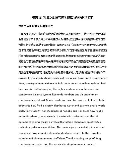
绕流线型回转体通气两相流动的非定常特性黄磊;王生捷;彭雪明;何春涛;段磊【摘要】为深入了解通气两相流的流场结构及水动力特性,在循环水洞中利用高速全流场显示技术及六分力天平测量技术,对绕流线型回转体通气两相流动的非定常特性进行实验研究.结果表明:弹身区域流场呈均匀分布的水气两相混合状态,流动稳定,非定常特性不明显;尾部区域流场较为紊乱,非定常特性明显,尾部空泡涡的周期性脱落引起模型阻力系数出现周期性脉动现象.绕流线型回转体通气两相流动的非定常特性与雷诺数及通气率有关.通气率的增加可降低由于尾部空泡涡的脱落而引起的阻力系数的波动幅度,而对尾部涡的脱落频率无明显影响;随着雷诺数的增加,由于尾部空泡涡的脱落而引起的阻力系数的波动幅度减小,尾部涡的脱落频率增加.%To explore the unsteady characteristics of two-phase flows and hydrodynamic force, the experiment with micro-hole array on a streamlined cylinder had been conducted by applying the high speed camera system and six-component balance system. Reynolds numbers and air entrainment coefficient are defined. Some conclusions can be drawn as follows: Elastic body area flow field is evenly distributed water and gas two-phase hybrid state, flow stability, non steadiness is not obvious; Tail areas flow field is more disordered, the unsteady characteristic is obvious, and the tail periodic shedding causes a cyclical fluctuation phenomenon of vortex cavitation resistance coefficient. The unsteady characteristic of ventilated two-phase flow around a streamlined cylinder relates to the Reynolds number and air entrainment coefficient. The fluctuating range of drag coefficient decreases and the vortex shedding frequency remainsunchanged as the air entrainment coefficient increases, and they all increase as the Reynolds numbers increases.【期刊名称】《哈尔滨工业大学学报》【年(卷),期】2017(049)007【总页数】5页(P178-182)【关键词】通气两相流;回转体;通气率;脉动;脱落【作者】黄磊;王生捷;彭雪明;何春涛;段磊【作者单位】北京机械设备研究所,北京100039;北京机械设备研究所,北京100039;北京机械设备研究所,北京100039;北京机械设备研究所,北京100039;北京机械设备研究所,北京100039【正文语种】中文【中图分类】TV131.2微气泡减阻具有较好的减阻效果和较弱的环境响应[1],其被认为是最有效的减阻方式之一. McCormick等[2]利用电解产生氢气泡的方法实现了减阻;Madvan等[3]采用多普勒测速仪研究了微气泡对湍流边界层的表面摩擦阻力的影响;Jinho等[4] 采用平板表面注气的方法实现减阻;Yoshiaki等[5]在循环水槽中针对不同平板进行了微气泡减阻实验;Kato等[6-7]进行了平板微气泡减阻实验,研究了气孔直径对减阻效果的影响特性,结果表明气孔直径对减阻效果影响极大;Sheng等[8]通过田口分析法研究了通气量、通气面积、气泡尺寸及来流速度对平板微气泡减阻效果的影响,结果表明通气量是主要影响因素;Deutsch等[9-10]采用通气缝出流方式,针对回转体模型研究了轴向压力梯度及气体成分对减阻效果的影响;Sanders等[11]提出了通过多孔质板向平板边界层内注入微气泡的方式,研究了不同速度下减阻效果随通气量的变化特性;Elbing等[12]改进了通气缝式出流方式,并对比了不同出流方式下的减阻效果. 董文才等[13]通过在回转体模型首部及中部开孔的方式,研究了不同区域组合通气对气泡减阻效果的影响;傅慧萍[14]研究了重力对平板气泡减阻的影响特性,认为重力对气泡减阻效率影响较大;李杰等[15]探索了尺寸效应及雷诺数对气泡减阻的影响特性. 由于通气两相流非定常过程的影响,模型阻力曲线会出现脉动现象,继而影响水中航行体的稳定性. 而目前针对气泡减阻的研究都是以阻力为研究对象进行的,并未对阻力时域曲线进行脉动分析. 本文针对微孔阵列式绕回转体模型,在封闭循环水洞中进行了通气两相流非定常特性实验研究,讨论了雷诺数Re及通气率Qv对流动非定常特性及模型水阻力脉动特性的影响.实验在循环水洞中进行,水洞具体参数参见文献[16]. 研究中采用六分力天平、水下绝压传感器、数据采集系统和高速摄像观察系统,分别对实验过程中的模型水阻力、通气量、流速、流场等进行记录.实验模型如图1所示,六分力天平安装于实验模型尾部,并与水洞尾支撑段固定连接. 天平测得的模型阻力数据通过动态测试分析系统进行采集,采集频率为1 024 Hz,采集时间为8 s,测量误差±0.1 N. 模型尾部距轴线16 mm处安装水下绝压传感器,压力传感器量程为0~100 kPa,线性精度为0.2%FS,采集频率为1 024 Hz,采集时间为8 s. 回转体模型长250 mm、直径40 mm,采用流线型头型以降低流场扰流对气泡减阻实验的影响. 模型表面微孔孔径为0.8 mm,沿轴向等距交错分布,共4排,排间距12 mm,首排孔距头部40 mm;每排共8个,且沿圆周方向均匀布置.本研究定义雷诺数Re、通气率Qv、压力系数Cp、阻力系数CD作为量纲一参数,且Re=VL/υ, Qv=Qin/(VS),Cp=p/(0.5ρV2), CD=R/(0.5ρV2S).式中:V为水洞工作段流速,L为实验模型长度,υ为水的动力黏度,Qin为通气量,S为回转体截面积,p为模型尾部压力,R为模型阻力.2.1 典型工况下的非定常特性分析本节通过分析模型水动力时域、频域曲线及流场形态,研究典型工况下的绕流线型回转体通气两相流动的非定常特性. 图2为雷诺数Re=2.03×10⁶、通气率Qv=0.014下模型阻力系数的时域曲线. 由图2可知,测量时间内阻力系数平均值基本不变,且阻力系数存在周期性脉动现象.为了更好地研究典型工况下的实验模型阻力系数的脉动特性,分析脉动频率,采用FFT变换将实验模型阻力系数信号的时域特性转换为频域特性进行分析. 图3为雷诺数Re=2.03×10⁶、通气率Qv=0.014下模型阻力系数的频域曲线.由图3可知,模型阻力系数变化的周期性较为明显,从功率谱密度较大可以看出,阻力系数变化的频率基本上为7.5 Hz.图4、5分别给出了雷诺数Re=2.03×10⁶、通气率Qv=0.014下尾部压力系数的时域及频域曲线. 由图4、5可知,测量时间内尾部压力系数均值基本不变,同样存在周期性脉动现象,脉动频率与模型阻力系数脉动频率相同,为7.5 Hz. 模型阻力由压差阻力及摩擦阻力两部分组成,尾部压力的变化将引起模型阻力的变化,因此可认为尾部压力的周期性脉动是引起模型阻力周期性脉动的主要原因.图6为Re=2.03×10⁶, Qv=0.014时通气两相流动形态随时间变化过程,图7为通气两相流形态图. 分析可知,气体经微孔喷出,在液相剪切流速的作用下形成气液两相流动,并沿下游发展. 在微孔近后方气泡表面光滑,紧贴壁面,呈细长透明形态;继续沿弹体表面向下游发展,细长透明气泡逐渐分裂成大量细碎气泡,流动区域内气泡与液相相互掺混,最终呈现均匀分布的水气两相混合状态. 各时刻弹身区域气液两相流流动较为稳定,非定常特性不明显. 进入尾部区域,气泡在尾部低压作用下形成回流,与液相相互掺混最终形成水气剧烈交换的云雾状模糊形态.回流区流场较为紊乱,水气混合边界呈收缩椭圆形,流动非定常特性明显,并伴有大尺度的云雾状空泡涡的断裂脱落现象,而且空泡涡的断裂脱落过程有明显的周期性. 在t 时刻空泡涡开始形成,并开始逐渐脱离尾部主流场的作用;在t+100 ms时刻,空泡涡完全脱落离尾部主流场,并开始沿来流方向运动. 尾部流场非定常变化的过程为空泡涡脱落的准周期运动过程,脱落周期约为100 ms. 进一步分析发现,尾部涡的脱落周期与尾部压力系数脉动频率相近,因此可认为,尾部涡的周期性脱落引起尾部压力系数产生周期性脉动现象,继而导致模型阻力系数出现周期性脉动.2.2 流动参数对水动力脉动特性影响图8给出了Re=1.49×10⁶、2.03×10⁶、2.48×10⁶下,模型阻力系数的波动范围随通气率的变化过程.图中波动幅度为最大阻力系数及最小阻力系数之差. 由图8可知,3种雷诺数下阻力系数脉动变化规律一致,存在饱和通气率;随着通气率的增加,模型阻力系数平均值下降,波动范围减小,直至饱和通气率;此后,继续增加通气率,阻力系数均值及其波动范围变化不明显. 进一步分析发现,R e=1.49×10⁶时,未通气下的阻力系数波动幅度及饱和通气率下的阻力系数波动幅度分别为0.053及0.040,Re=2.03×10⁶时分别为0.028及0.019,Re=2.48×10⁶时分别为0.026及0.016,由此可知雷诺数的增加将使阻力系数波动幅度降低. 综上分析,通气率及雷诺数的增加都将降低模型阻力系数的波动幅度. 进一步分析认为,通气率及雷诺数的增加使得两相流的不稳定性增加,模型尾部湍流掺混增强,从而引起尾部绕流分离点向下游移动,使得尾部回流区减弱,继而降低了阻力系数的脉动幅度,这与经典的流动分离理论相似.图9给出了Re=1.49×10⁶、2.03×10⁶、2.48×10⁶下,模型阻力系数脉动频率随通气率的变化特性.1)描述了典型工况下通气两相流的流动过程,弹身区域流场呈均匀分布的水气两相混合状态,流动稳定,非定常特性不明显;尾部区域流场较为紊乱,非定常特性明显,尾部空泡涡的周期性脱落引起模型阻力系数出现周期性脉动现象.2) 绕流线型回转体通气两相流动的非定常特性与雷诺数及通气率有关. 通气率的增加可降低由于尾部涡的脱落而引起的阻力系数的波动幅度,而对尾部涡的脱落频率无明显影响;随着雷诺数的增加,由于尾部涡的脱落而引起的阻力系数的波动幅度减小,尾部涡的脱落频率增加.【相关文献】[1] WU S J, OUYANG K, SHIAH S W. Robust design of microbubble reduction in a channel flow using the Taguchi method [J]. Ocean Engineering, 2008, 35(8):856-863.DOI:10.1016/j.oceaneng.2008.01.022.[2] MCCORMICK M E, BHATTACHARYA R. Drag reduction of a submersible hull by electrolysis [J]. Naval Engineers Journal, 1973, 85(2):11-16. DOI:10.1111/j.1559-3584.1973.tb04788.x.[3] MAVAN N K, DEUTSCH S, MERKLE C L. Reduction of turbulent skin friction by microbubble[J]. Physics of Fluids,1984, 27(2):356-368. DOI:10.1063/1.864620.[4] JINHO J, CHOI S H, KIM B, et al. Experiment investigation of frictional resistance reduction with air layer on the hull bottom of a ship[J]. Ocean Engineering, 2014, 6(2):363-379. DOI:10.2478/IJNAOE-2013-0185.[5] YOSHIAKI K, TAKAHITO T. Experimental study on microbubbles and their applicability to ships for skin friction reduction[J]. International Journal of Heat and Fluid Flow, 2000, 21(5):582-588.DOI:10.1016/S0142-727X(00)00048-5.[6] KATO H. Experimental study on microbubble injection method for frictional drag reduction [J]. Journal of Marine Science and Technology, 1998, 3(3): 122-129.DOI:10.1007/BF02492919.[7] KATO H, MIYANAGA M, HARAMOTO Y, et al. Frictional drag reduction by injecting bubbly water into turbulence boundary layer [C]//ASME Fluids Engineering Divisionsummer meeting. New York: ASME, 1994 : 185-194.[8] OUYANG K, WU S J, HUANG H H. Optimum parameter design of microbubble drag reduction in a turbulent flow by the Taguchi me-thod combined with artificial neural networks [J]. Journal of Fluids Engineering, 2013, 135(11):1-11.DOI:10.1115/1.4024930. [9] DEUTSCH S, CASTANO J. Microbubble skin reduction on an axisymmetric body[J]. Physics of Fluids, 1986, 29(11):3590-3597. DOI:10.1063/1.865786.[10]CLARK H, DEUTSCH S. Microbubble skin reduction on an axisymmetric body under the influence of applied axial pressure gradients [J]. Physics of Fluids A, 1991, 3(12):2948-2954. DOI:10.1063/1.857837.[11]SANDERS W C, WINKEL E S, DOWLING D R, et al. Bubble friction drag reduction in a high-Reynolds-number flat-plate turbulent boundary layer [J]. Journal of Fluid Mechanics, 2006, 552:353-380.DOI:10.1017/S0022112006008688.[12]ELBINGL B R, WINKEL E S, LAY K S, et al. Bubble-induced skin-friction drag reduction and the abrupt transition to air-layer drag reduction[J]. Journal of Fluid Mechanics, 2008,612: 201-236. DOI:10.1017/S0022112008003029.[13] 董文才,周晨,张军. 回转体气层减阻降噪模型试验研究[J]. 海军工程大学学报, 2011,23(3):5-9. DOI:10.3969/j.issn.1009-3486.2011.03.002.DONG Wencai, ZHOU Chen, ZHANG Jun. Gyrodidal model experiment on resistance and noise reduction by bubble layer[J]. Journal of Naval University of Engineering,2011,23(3):5-9. DOI:10.3969/j.issn.1009-3486.2011.03.002.[14]傅慧萍. 平板微气泡减阻数值模拟及影响因素分析[J].哈尔滨工程大学学报,2015,36(10): 1297-1302.DOI:10.11990/jheu.201407002.FU Huiping. Numerical simulation of microbubble drag reduction in a plate and factors in fluencing its practicality process[J]. Journal of Harbin Engineering University, 2015,36(10): 1297-1302. DOI:10.11990/jheu.201407002.[15]傅慧萍, 李杰. 微气泡减阻的数值模拟方法及尺寸效应[J].上海交通大学学报,2016,50(2): 278-282.DOI:10.16183/ki.jsjtu.2016.02.020.FU Huiping, LI Jie. Numerical simulation of micro-bubbles drag reduction and scaleeffect[J]. Journal of Shanghai Jiao Tong University, 2016,50(2): 278-282.DOI:10.16183/ki.jsjtu.2016.02.020.[16]王威.通气参数对水下航行体流体动力影响[D]. 哈尔滨:哈尔滨工业大学,2013.WANG Wei. Experimental research on effect of ventilation parameters on hydrodynamic characteristic of under water vehicle [D]. Harbin: Harbin Institute of Technology,2013.。

排气三通管道分散流流动特性的数值模拟及分析李雄;刘伟军;唐飘;杜兴慧【摘要】为减小排气T型三通管道中的局部压力损失,利用FLUENT软件对其分散流动特性进行数值模拟,分析支管与总管流通截面积比、夹角、质量流量比及流体温度对管道总压损失系数的影响规律.结果表明:总管流速和气体温度对总压损失系数影响不大,支管与总管质量流量比却对总压损失系数影响显著;分支管与总管夹角、分支管与总管流通截面比对总管-通支管总压损失系数的影响不明显,但对总管-分支管总压损失系数的影响显著.通过数值模拟和分析建议T型三通管推荐结构为分支管与总管夹角α=45°,分支管与总管流通截面比A3/A1的适宜范围为0.8~1.数值模拟结果与前人研究及试验结果比对,趋势一致,计算精度较高,可为类似汽车排气分流技术开发提供依据.【期刊名称】《河北科技大学学报》【年(卷),期】2014(035)003【总页数】7页(P272-278)【关键词】三通管道;分散流;压力损失系数;数值模拟【作者】李雄;刘伟军;唐飘;杜兴慧【作者单位】上海工程技术大学汽车工程学院,上海 201620;上海工程技术大学机械工程学院,上海201620;上海工程技术大学汽车工程学院,上海 201620;上海工程技术大学汽车工程学院,上海 201620【正文语种】中文【中图分类】TK403在车用发动机中,受工作原理限制,燃料转变为有用功的部分占1/3左右,大部分的热量通过冷却介质和废气被带走[1-3]。
发动机排气管中上游的废气为较高品位的热源,若能有效回收这部分能量,对提高发动机的燃油经济性具有重要的意义。
排气三通管道作为发动机尾气余热回收利用装置的重要组成部分,不仅对尾气能否正常利用起着关键作用,而且影响着发动机的整体性能。
三通是最常见的一种管道配件,三通处的流动十分复杂,流体的流速在此处发生突变,出现流体质点之间的撞击,产生漩涡,二次流以及流动的分离和再附壁等现象[4-5]。
摘要摘要表面活性剂是一大类有机化合物,它们的性质极具特色,应用极为灵活、广泛,有很大的应用价值和理论意义。
即能大大降低溶剂的表面张力,改变体系的界面结构与组成。
成为人们改变界面性质以适应各种要求的重要手段。
蠕虫状胶束是指表面活性剂球状胶束沿非轴方向一维增长形成的热力学平衡态。
尽管目前对化学减阻剂(这里指高分子聚合物减阻剂和表面活性剂减阻剂)已经有了相当规模的实际系统应用研究或工业应用,但由于对湍流本身的了解还不够全面,表面活性剂在湍流中产生减阻的原因至今尚不十分清楚。
围绕减阻机理,曾提出一些假设和模型,但没有一种理论可以圆满解释添加剂湍流减阻流动中的所有实验现象,减阻机理还有深入研究。
关键词:表面活性剂,蠕虫状胶束,减阻机理。
IABSTRACTABSTRACTSurfactant is a kinds of organic compounds ,Their distinctive character ,Extremely flexible application. Has great application value and theoretical significance. Which can greatly reduce the surface tension of the solvent. Change the system's interface structure and composition. As people change interface properties to meet the various requirements of the important means. Worm-like micelles is refers to the surfactant spherical micelles formed along the axial one-dimensional growth thermodynamic equilibrium state.Despite the current to the chemical drag reduction agent (here refers to the polymer reduction agent and surfactant drag reduction agent) has a considerable scale of actual system application research, or industrial applications. But due to the understanding of turbulence itself is not enough comprehensive, surfactant causes of drag reduction in turbulent flow is still not very clear. Around the drag reduction mechanism, has put forward some assumptions and models, but no one theory can explain satisfactorily additive turbulent drag reduction flow all of the experimental phenomena, the drag reduction mechanism and further research.Key words: The surfactant,Worm-like micelles,The drag reduction mechanismII目录1 引言 (1)2 表面活性剂简介 (2)2.1 表面活性剂的基本性质 (2)2.2 表面活性剂的分类 (2)2.3 阳离子表面活性剂的性质 (2)3 表面活性剂聚集体 (4)3.1 胶束的来源及定义 (4)3.2 胶束的结构 (4)3.3 蠕虫状胶束 (5)4 蠕虫状胶束 (6)4.1 概念 (6)4.2 发现和历史 (6)4.3 应用 (7)5 表面活性剂减阻性能的测试 (8)5.1 减阻的理论基础 (8)5.2 表面活性剂湍流减阻流动特性 (9)5.3 表面活性剂减阻流动特性的影响因素 (11)5.3.1 溶液浓度的影响 (11)5.3.2 流体温度的影响 (12)5.3.3 抗离子添加剂的影响 (12)5.3.4 金属离子和金属化合物的影响 (13)5.4 表面活性剂水溶液减阻机理假说 (13)5.4.1 剪切稀化假说 (14)5.4.2 弹性缓冲层减阻假说 (14)5.4.3 紊流强度抑制假说 (14)III5.4.4 解耦假说 (14)5.4.5 粘弹性假说 (14)6 未来发展前景 (16)参考文献 (17)致谢 ............................................... 错误!未定义书签。
油品减阻剂减阻机理及其效果预测研究现状全青;王寿喜;石营;王力;解谨;王小丹【摘要】从减阻机理、减阻率预测和数值模拟3个方面介绍了目前主流的聚合物减阻机理、现场对减阻率预测存在的问题与难点和数值模拟减阻过程的短板,总结了减阻剂的研究现状与存在的问题,为实现减阻剂高效合理的利用指明了研究方向.【期刊名称】《化工机械》【年(卷),期】2019(046)001【总页数】5页(P16-20)【关键词】输油管道;油品减阻剂;减阻机理;减阻率预测;数值模拟研究【作者】全青;王寿喜;石营;王力;解谨;王小丹【作者单位】西安石油大学石油工程学院;西安石油大学石油工程学院;西安石油大学石油工程学院;西安石油大学石油工程学院;西安石油大学石油工程学院;西安石油大学石油工程学院【正文语种】中文【中图分类】TQ055.8+1油品管输过程中添加高分子聚合物即减阻剂,可以明显降低管路系统摩阻、提高管道输送能力,具有广阔的市场应用前景和巨大的商业价值。
但目前由于油品减阻剂减阻效果预测体系的缺失,使得减阻剂在输油管道现场的应用只能通过现场实验的方法来确定减阻剂的优选和添加浓度,而且减阻剂的选取和使用没有明确的规定,仅通过实验装置进行实验研究来确定该减阻剂是否应用于达不到预期输量要求的管线中,这极大地限制了减阻剂在设计阶段的工艺优化、运行阶段的推广应用和管输系统的节能降耗。
因此,笔者从减阻机理、减阻率预测和数值模拟3个方向全面探究油品减阻剂的研究进展,为后续减阻剂在输油管道中的合理、高效应用提供指导,使减阻剂在管输初期即起到节能减排的作用。
1 减阻机理减阻剂依据合成方法可分为水溶性和油溶性两大类,其中油溶性的高分子聚合物减阻剂以其用量小、无污染等特点广泛应用在现场管输中。
1.1 高分子聚合物减阻剂减阻机理对油品减阻剂减阻的研究始于20世纪80年代初,目前提出的减阻剂机理有:Toms伪塑性假说、Virk的有效滑移假说、粘弹性假说、湍流脉动抑制假说和湍流脉动解耦假说。
第47卷第2期2021年4月航空发动机AeroengineVol.47No.2Apr.2021“仿生学”沟槽减阻仿真分析及机理研究陈璠1,徐朋飞2(1.中国航空发动机研究院,北京101300;2.中国航发沈阳发动机研究所,沈阳110015)摘要:“仿生学”沟槽结构在航空发动机叶片减阻和燃滑油系统减阻等领域有潜在的应用前景。
为获得该结构构型参数和雷诺数对减阻效果的影响规律,通过对鲨鱼及海豚表皮特征进行仿生设计了横向和纵向沟槽,利用数值模拟方法对不同沟槽构型在不同雷诺数下的减阻效果开展了对比研究和机理分析。
结果表明:横向和纵向沟槽构型减阻率均随雷诺数增大而减小,并且雷诺数影响占主导地位。
对于横向沟槽构型,沟槽间距较大的构型沿程阻力占主导,在相对高雷诺数下减阻效果较好;沟槽数量较多的构型局部阻力占主导,在相对低雷诺数下减阻效果较好;无间距构型在相对低雷诺数下减阻效果最好,减阻率约为4.14%。
对于纵向沟槽构型,减阻率比横向沟槽的高约1个百分点,雷诺数对减阻效果影响不大。
关键词:沟槽;减阻率;仿生学;局部阻力;沿程阻力;雷诺数;航空发动机中图分类号:V211文献标识码:Adoi :10.13477/ki.aeroengine.2021.02.005Simulation Analysis and Mechanism Study on Drag Reduction of “Bionics ”GrooveCHEN Fan 1,XU Peng-fei 2(1.Aero Engine Academy of China ,Beijing 101300,China ;2.AECC Shenyang Engine Research Institute ,Shenyang 110015,China )Abstract :"Bionics"groove structure has potential application prospect in fields of aeroengine blades drag reduction and fuel /oil system drag reduction.In order to obtain the structure configuration parameters and the influence of the Reynolds number on the drag reduction ,transverse and longitudinal grooves were designed with the bionics of the skin characteristics of sharks and parative study and mechanism analysis of drag reduction effect were carried out for different groove configuration by numerical simulation method under different Reynolds number.The results show that the drag reduction rates of both transverse and longitudinalgrooves configuration decrease with the increase of Reynolds number ,and the influence of Reynolds number is dominant.For the transverse groove with larger groove gap ,the resistance loss along the way is dominant ,and the drag reduction effect is better at relatively high Reynolds number.The local drag is dominant with more grooves ,and the drag reduction effect is better at relatively low Reynoldsnumber.The drag reduction effect of the no gap configuration is the best at relatively low Reynolds number ,and the drag reduction rate is about 4.14%.For the longitudinal groove configuration ,the drag reduction rate is about 1%higher than that of the transverse groove configuration ,and Reynolds number has little effect on the drag reduction.Key words :groove ;drag reduction rate ;bionics ;local resistance loss ;resistance loss along the way ;Reynolds number ;aeroengine收稿日期:2019-04-15基金项目:航空动力基础研究项目资助作者简介:陈璠(1991),男,硕士,工程师,主要从事航空发动机仿真技术研究工作;E-mail :****************。
2017年考研英语一真题原文及答案解析完整版SectionⅠUse of EnglishDirections:Read the following text.Choose the best word(s)for each numbered blank andmark A,B,C or D on the ANSWER SHEET.(10 points)Could a hug a day keep the doctor away?The answer may be aresounding"yes!"_____(1)helping you feel close and_____(2)to people you care about,it turns out that hugs can bring a____(_ 3)of health benefits to your body andmind.Believe it or not,a warm embrace might even help you____(_4)getting sick this winter.In a recent study_____(5)over 400 healthy adults,researchers from CarnegieMellon University in Pennsylvania examined the effects of perceived social supportand the receipt of hugs_____(6)the participants' susceptibility to developing thecommon cold after being_____(7)to the virus.People who perceived greater social support were less likely to come_____(8)with a cold,and the researchers____(_ 9)that the stress-reducing effects of hugging____(_ 10)about 32 percent of thatbeneficial effect._____(11)among those who got a cold,the ones who felt greatersocial support and received more frequent hugs had less severe___(__12)."Hugging protects people who are under stress from the___(__13)risk for coldsthat's usually_____(14)with stress,"notes Sheldon Cohen,a professor of psychologyat Carnegie,Hugging"is a marker of intimacy and help_____(15)the feeling thatothers are there to help____(_16)difficulty."Some experts____(_ 17)the stress-reducing,health-related benefits of hugging tothe release of oxytocin,often called"the bonding hormone"____(_18)it promotes attachment in relationships,including that between mothers and their newbornbabies.Oxytocin is made primarily in the central lower part of the brain,and some of itis released into the bloodstream.But some of it____(_ 19)in the brain,where it_____(20)mood,behavior and physiology.1.A.Besides B.Unlike C.Throughout D.Despite2.A.equal B.restricted C.connected D.inferior3.A.view B.Host C.lesson D.choice4.A.avoid B.forget C.recall D.keep5.A.collecting B.affecting C.guiding D.involving6.A.on B.in C.at D.of7.A.devoted B.attracted C.lost D.exposed8.A.along B.across C.down D.out9.A.imagined B.denied C.doubted D.calculated10.A.served B.Restored C.explained D.required11.A.Thus B.Still C.Rather D.Even12.A.defeats B.symptoms C.errors D.tests13.A.Highlighted B.increased C.controlled D.minimized14.A.Presented B.equipped C.associated D.compared15.A.assess B.Generate C.moderate D.record16.A.in the name of B.in the form of C.in the face of D.in the way of17.A.attribute B.commit C.transfer D.return18.A.unless B.because C.though D.until19.A.remains B.emerges C.vanishes D.decreases20.A.experiences B.combines C.justifies D.influencesSectionⅡReading ComprehensionPart ADirections:Read the following four texts.Answer the questions below each text by choosingA,B,C or D.Mark your answers on the ANSWER SHEET.(40 points)Text 1First two hours,now three hours—this is how far in advance authorities arerecommending people show up to catch a domestic flight,at least at some majorU.S.airports with increasingly massive security lines.Americans are willing to tolerate time-consuming security protocols in return forincreased safety.The crash of Egypt Air Flight 804,which terrorists may have downed over the Mediterranean Sea,provides another tragic reminder of why.But demanding too much of air travelers or providing too little security in return undermines public support for the process.And it should:Wasted time is a drag on Americans' economic and private lives,not to mention infuriating.Last year,the Transportation Security Administration(TSA)found in a secretcheck that undercover investigators were able to sneak weapo—nsboth fake and real —past airport security nearly every time they tried.Enhanced security measures since then,combined with a rise in airline travel due to the improving economy and low oil prices,have resulted in long waits at major airports such as Chicago's O'Hare International.It is not yet clear how much more effective airline security has become —but the lines are obvious.Part of the issue is that the government did not anticipate the steep increase in airline travel,so the TSA is now rushing to get new screeners on the line.Part of the issue is that airports have only so much room for screening lanes.Another factor may be that more people are trying to overpack their carry-on bags to avoidchecked-baggage fees,though the airlines strongly dispute this.There is one step the TSA could take that would not require remodeling airports or rushing to hire:Enroll more people in the PreCheck program.PreCheck is supposed to be a win-win for travelers and the TSA.Passengers who pass a background check are eligible to use expedited screening lanes.This allows the TSA to focus on travelers who are higher risk,saving time for everyone involved.TSA wants to enroll 25 million people in PreCheck.It has not gotten anywhere close to that,and one big reason is stickershock:Passengers must pay$85 every five years to process their background checks.Since the beginning,this price tag has been PreCheck's fatal flaw.Upcoming reforms might bring the price to a more reasonable level.But Congress should look into doing so directly,by helping to finance PreCheck enrollment or to cut costs in other ways.The TSA cannot continue diverting resources into underused PreCheck laneswhile most of the traveling public suffers in unnecessary lines.It is long past time to make the program work.21.The crash of Egypt Air Flight 804 is mentioned to[A]explain American’s tolerance of current security checks.[B]stress the urgency to strengthen security worldwide.[C]highlight the necessity of upgrading major U.S.airports.[D]emphasize the importance of privacy protection.22.Which of the following contributes to long waits at major airports?[A]New restrictions on carry-on bags.[B]The declining efficiency of the TSA.[C]An increase in the number of travellers.[D]Frequent unexpected secret checks.23.The word“expedited”(Liner 4,Para.5)is closet in meaning to[A]quieter.[B]cheaper.[C]wider.[D]faster.24.One problem with the PreCheck program is[A]a dramatic reduction of its scale.[B]its wrongly-directed implementation.[C]the government’s reluctance to back it.[D]an unreasonable price for enrollment.25.Which of the following would be the best title for the text?[A]Less Screening for More Safety[B]PreCheck– a Belated Solution[C]Getting Stuck in Security Lines[D]Underused PreCheck LanesText 2“The ancient Hawaiians were astronomers”, wrote Queen Liliuokalani,Hawaii's last reigning monarch,in 1897.Star watchers were among the most esteemed membersof Hawaiian society.Sadly,all is not well with astronomy in Hawaii today.Protestshave erupted over construction of the Thirty Meter Telescope(TMT),a giant observatory that promises to revolutionize humanity's view of the cosmos.At issue is the TMT's planned location on Mauna Kea,a dormant volcano worshiped by some Hawaiians as the piko,that connects the Hawaiian Islands to the heavens.But Mauna Kea is also home to some of the world's most powerful telescopes.Rested in the Pacific Ocean,Mauna Kea's peak rises above the bulk of our planet's dense atmosphere,where conditions allow telescopes to obtain images of unsurpassed clarity.Opposition to telescopes on Mauna Kea is nothing new.A small but vocal group of Hawaiians and environmentalists have long viewed their presence as disrespect far sacred land and a painful reminder of the occupation of what was once a sovereign nation.Some blame for the current controversy belongs to astronomers.In their eagerness to build bigger telescopes,they forgot that science is not the only way of understanding the world.They did not always prioritize the protection of Mauna Kea's fragile ecosystems or its holiness to the islands'inhabitants.Hawaiian culture is not a relic of the past;it is a living culture undergoing a renaissance today.Yet science has a cultural history,too,with roots going back to the dawn of civilization.The same curiosity to find what lies beyond the horizon that first brought early Polynesians to Hawaii's shores inspires astronomers today to explore the heavens.Calls to disassemble all telescopes on Mauna Kea or to ban future development there ignore the reality that astronomy and Hawaiian culture both seek to answer big questions about who we are,where we come from and where we are going.Perhaps that is why we explore the starry skies,as if answering a primal calling to know ourselves and our true ancestral homes.The astronomy community is making compromises to change its use of Mauna Kea.The TMT site was chosen to minimize the telescop’e s visibility around the island and to avoid archaeological and environmental impact.To limit the number of telescopes on Mauna Kea,old ones will be removed at the end of their lifetimes andtheir sites returned to a natural state.There is no reason why everyone cannot be welcomed on Mauna Kea to embrace their cultural heritage and to study the stars.26.Queen Liliuokalani’s remark in Paragraph 1 indicates[A]her conservative view on the historical role of astronomy.[B]the importance of astronomy in ancient Hawaiian society.[C]the regrettable decline of astronomy in ancient times.[D]her appreciation of star watchers’f eats in her time.27.Mauna Kea is deemed as an ideal astronomical site due to[A]its geographical features.[B]its protective surroundings.[C]its religious implications.[D]its existing infrastructure.28.The construction of the TMT is opposed by some locals partly because[A]it may risk ruining their intellectual life.[B]it reminds them of a humiliating history.[C]their culture will lose a chance of revival.[D]they fear losing control of Mauna Kea.29.It can be inferred from Paragraph 5 that progress in toda’y s astronomy[A]is fulfilling the dreams of ancient Hawaiians.[B]helps spread Hawaiian culture across the world.[C]may uncover the origin of Hawaiian culture.[D]will eventually soften Hawaiians ’hostility.30.The author’s attitude toward choosing Mauna Kea as the TMT site is one of[A]severe criticism.[B]passive acceptance.[C]slight hesitancy.[D]full approval.Text 3Robert F.Kennedy once said that a country's GDP measur“e severything exceptthat which makes life worthwhile.”With Britain voting to leave the EuropeanUnion,and GDP already predicted to slow as a result,it is now a timely moment to assess what he was referring to.The question of GDP and its usefulness has annoyed policymakers for over half a century.Many argue that it is a flawed concept.It measures things that do not matter and misses things that do.By most recent measures,the U’K s GDP has been the envy of the Western world,with record low unemployment and high growth figures.If everything was going so well,then why did over 17 million people vote forBrexit,despite the warnings about what it could do to their country’s economic prospects?A recent annual study of countries and their ability to convert growth intowell-being sheds some light on that question.Across the 163 countries measured,the UK is one of the poorest performers in ensuring that economic growth is translated into meaningful improvements for its citizens.Rather than just focusing on GDP,over 40 different sets of criteria from health,education and civil society engagement have been measured to get a more rounded assessment of how countries are performing.While all of these countries face their own challenges,there are a number of consistent themes.Yes,there has been a budding economic recovery since the 2008 global crash,but in key indicators in areas such as health and education,major economies have continued to decline.Yet this is’n t the case with all countries.Some relatively poor European countries have seen huge improvements across measures including civil society,income equality and environment.This is a lesson that rich countries can learn:When GDP is no longer regarded as the sole measure of a countr’y s success,the world looks very different.So what Kennedy was referring to was that while GDP has been the most common method for measuring the economic activity of nations,as a measure,it is no longer enough.It does not include important factors such as environmental quality or education outcomes–all things that contribute to a person's sense of well-being.The sharp hit to growth predicted around the world and in the UK could lead to a decline in the everyday services we depend on for our well-being and for growth.Butpolicymakers who refocus efforts on improving well-being rather than simply worrying about GDP figures could avoid the forecasted doom and may even see progress.31.Robert F.Kennedy is cited because he[A]praised the UK for its GDP.[B]identified GDP with happiness.[C]misinterpreted the role of GDP.[D]had a low opinion of GDP.32.It can be inferred from Paragraph 2 that[A]the UK is reluctant to remold its economic pattern.[B]the UK will contribute less to the world economy.[C]GDP as the measure of success is widely defied in the UK.[D]policymakers in the UK are paying less attention to GDP.33.Which of the following is true about the recent annual study?[A]It excludes GDP as an indicator.[B]It is sponsored by 163 countries.[C]Its criteria are questionable.[D]Its results are enlightening.34.In the last two paragraphs,the author suggests that[A]the UK is preparing for an economic boom.[B]high GDP foreshadows an economic decline.[C]it is essential to consider factors beyond GDP.[D]it requires caution to handle economic issues.35.Which of the following is the best for the text?[A]High GDP But Inadequate Well-being,a UK lesson[B]GDP figures,a Window on Global Economic Health[C]Robert F.Kennedy,a Terminator of GDP[D]Brexit,the UK ’s Gateway to Well-beingText 4In a rare unanimous ruling,the US Supreme Court has overturned the corruptionconviction of a former Virginia governor,Robert McDonnell.But it did so whileholding its nose at the ethics of his conduct,which included accepting gifts such as a Rolex watch and a Ferrari Automobile from a company seeking access to government.The high court’s decision said the judge in Mr.McDonnel’l s trail failed to tell a jury that it must look only at his“official acts,”or the former governor’s decisions on “specific”and“unsettled”issues related to his duties.Merely helping a gift-giver gain access to other officials,unless done with clear intent to pressure those officials,is not corruption,the justices found.The court did suggest that accepting favors in return for opening doors is “distasteful”a nd“nasty.”B ut under anti-bribery laws,proof must be made of concrete benefits,such as approval of a contract or regulation.Simply arranging ameeting,making a phone call,or hosting an event is not a“n official act.”The court’s ruling is legally sound in defining a kind of favoritism that is not criminal.Elected leaders must be allowed to help supporters deal with bureaucratic problems without fear of prosecution of bribery.“The basic compact underlying representative government”,wrote Chief Justice John Roberts for the cour“t, assumes that public officials will hear from their constituents and act on their concerns”.But the ruling reinforces the need for citizens and their elected representatives,not the courts,to ensure equality of access to government.Officials must not be allowed to play favorites in providing information or in arranging meetings simply because an individual or group provides a campaign donation or a personal gift.This type of integrity requires will-enforced laws in government transparency,such as records of official meetings,rules on lobbying,and information about each elected leade’r s source of wealth.Favoritism in official access can fan public perceptions of corruption.But it is not always corruption.Rather officials must avoid double standards,or different types of access for average people and the wealthy.If connections can be bought,a basic premise of democratic society–that all are equal in treatment by government-is undermined.Good government rests on an understanding of the inherent worth of each individual.The court’s ruling is a step forward in the struggle against both corruption and official favoritism.36.The underlined sentence(Para.1)most probably shows that the court[A]avoided defining the extent of McDonnell ’s duties.[B]made no compromise in convicting McDonnell.[C]was contemptuous of McDonnell’s conduct.[D]refused to comment on McDonnell’s ethics.37.According to Paragraph 4,an official act is deemed corruptive only if it involves[A]concrete returns for gift-givers.[B]sizable gains in the form of gifts.[C]leaking secrets intentionally.[D]breaking contracts officially.38.The court’s ruling is d on the assumption that public officials are[A]allowed to focus on the concerns of their supporters.[B]qualified to deal independently with bureaucratic issues.[C]justified in addressing the needs of their constituents.[D]exempt from conviction on the charge of favoritism.39.Well-enforced laws in government transparency are needed to[A]awaken the conscience of officials.[B]guarantee fair play in official access.[C]allow for certain kinds of lobbying.[D]inspire hopes in average people.40.The author’s attitude toward the cour’t s ruling is[A]sarcastic.[B]tolerant.[C]skeptical.[D]supportive.Part BDirections:The following paragraphs are given in a wrong order.For questions 41-45,you are required to reorganize these paragraphs into a coherent text by choosing from the list A-G and filling them into the numbered boxes.Paragraphs B and D have been correctly placed.Mark your answers on the ANSWER SHEET(. 10 points)[A]The first published sketch,"A Dinner at Polar Walk"brought tears to Dickens's eyes when he discovered it in the pages of The Monthly Magazine From then on his sketches,which appeared under the pen name"Boz" in The Evening Chronicle,earned him a modest reputation.[B]The runaway success of The Pickwick Papers,as it is generally knowntoday,secured Dickens's fame.There were Pickwick coats and Pickwick cigars,and the plump,spectacled hero,Samuel Pickwick,because a national figure.[C]Soon after Sketches by Boz appeared,a publishing firm approached Dickensto write a story in monthly installments,as a backdrop for a series of woodcuts by the then-famous artist Robert Seymour,who had originated the idea for the story.With characteristic confidence,Dickens successfully insisted that Seymour's pictures illustrate his own story instead.After the first installment,Dickens wrote to the artistand asked him to correct a drawing Dickens felt,was not faithful enough to hisprose.Seymour made the change,went into his backyard,and expressed his displeasure by committing suicide.Dickens and his publishers simply pressed on with a new artist.The comic novel,The Posthumous Papers of the Pickwick Club,appeared serially in 1836 and 1837 and was first published in book form in 1837.[D]Charles Dickens is probably the best-known and,to many people,the greatest English novelist of the 19th century.A moralist,satirist,and social reformer,Dickens crafted complex plots and striking characters that capture the panorama of English society.[E]Soon after his father's release from prison,Dickens got a better job as errand boy in law offices.He taught himself shorthand to get an even better job later as acourt stenographer and as a reporter in Parliament.At the same time,Dickens,who had a reporter's eye for transcribing the life around him,especially anything comic orodd,submitted short sketches to obscure magazines.[F]Dickens was born in Portsmouth,on England's southern coast.His father was a clerk in the British Navy Pay office--a respectable position,but with little social status.His paternal grandparents,a steward and a housekeeper,possessed even less status,having been servants,and Dickens later concealed their background.Dicken's mother supposedly came from a more respectable family.Yet two years before Dicken's birth,his mother's father was caught stealing and fled to Europe,never to return.The family's increasing poverty forced Dickens out of school at age 12 to work in Warren's Blacking Warehouse,a shoe-polish factory,where the other working boys mocked him as"the young gentleman."His father was then imprisoned for debt.The humiliations of his father's imprisonment and his labor in the blacking factory formed Dickens's greatest wound and became his deepest secret.He could not confide them even to his wife,although they provide the unacknowledged foundation of his fiction.[G]After Pickwick,Dickens plunged into a bleaker world.In Oliver Twist,hetraces an orphan's progress from the workhouse to the criminal slums ofLondon.Nicholas Nickleby,his next novel,combines the darkness of Oliver Twist with the sunlight of Pickwick.The popularity of these novels consolidated Dickens' as a nationally and internationally celebrated man of letters.Part CDirections:Read the following text carefully and then translate the underlined segments into Chinese.Your translation should be written neatly on the ANSWER SHEET.(10 points)The growth of the use of English as the world`s primary language for international communication has obviously been continuing for severaldecades.(46)But even as the number of English speakers expands further there are signs that the global predominance of the language may fade within the foreseeable future.Complex international, economic, technological and culture change could start to diminish the leading position of English as the language of the world market, and UK interests which enjoy advantage from the breath of English usage would consequentlyface new pressures. Those realistic possibilities are highlighted in the study presented by David Graddol. (47)His analysis should therefore end any self-contentedness among those who may believe that the global position of English is so stable that the young generation of the United Kingdom do not need additional language capabilities.David Graddol concludes that monoglot English graduates face a bleak economic future as qualified multilingual youngsters from other countries are proving to have a competitive advantage over their British counterparts in global companies and organizations. Alongside that,(48)many countries are introducing English into the primary-school curriculum but British schoolchildren and students do not appear to be gaining greater encouragement to achieve fluency in other languages. If left to themselves, such trends will diminish the relative strength of the English language in international education markets as the demand for educational resources in languages, such as Spanish ,Arabic or Mandarin grows and international business process outsourcing in other language such as Japanese, French and German, spreads.(49)The changes identified by David Graddol all present clear and major challenges to UK`s providers of English language teaching to people of other countries and to broader education business sectors. The English language teaching sector directly earns nearly &1.3 billion for the UK in invisible exports and our other education related explores earn up to &10 billion a year more. As the international education market expands, the recent slowdown in the number of international students studying in the main English-speaking countries is likely to continue, especially if there are no effective strategic policies to prevent such slippage.The anticipation of possible shifts in demand provided by this study is significant:(50) It gives a basis to all organization which seek to promote the learning and very different operating environment. That is a necessary and practical approach. In this as in much else, those who wish to influence the future must prepare for it.SectionⅣWriting51 directionsYou are to write an email to James Cook,a newly-arrived Australiaprofessor,recommending some tourist attraction in your city.Please give reasons foryour recommendation.You should write neatly on the answer sheet.Do not sign your own name at the end of the “e Li Ming ”instead.Do not write the address。
力学mechanics牛顿力学Newtonian mechanics经典力学classical mechanics静力学statics运动学kinematics动力学dynamics动理学kinetics宏观力学macroscopic mechanics,macromechanics 细观力学mesomechanics微观力学microscopic mechanics,micromechanics 一般力学general mechanics固体力学solid mechanics流体力学fluid mechanics理论力学theoretical mechanics应用力学applied mechanics工程力学engineering mechanics实验力学experimental mechanics计算力学computational mechanics理性力学rational mechanics物理力学physical mechanics地球动力学geodynamics力force作用点point of action作用线line of action力系system of forces力系的简化reduction of force system 等效力系equivalent force system刚体rigid body力的可传性transmissibility of force平行四边形定则parallelogram rule力三角形force triangle力多边形force polygon零力系null-force system平衡equilibrium 。
,力的平衡equilibrium of forces平衡条件equilibrium condition平衡位置equilibrium position平衡态equilibrium state分析力学analytical mechanics拉格朗日乘子Lagrange multiplier拉格朗日[量] Lagrangian拉格朗日括号Lagrange bracket循环坐标cyclic coordinate循环积分cyclic integral哈密顿[量] Hamiltonian哈密顿函数Hamiltonian function正则方程canonical equation正则摄动canonical perturbation正则变换canonical transformation正则变量canonical variable哈密顿原理Hamilton principle作用量积分action integral哈密顿--雅可比方程Hamilton-Jacobi equation 作用--角度变量action-angle variables阿佩尔方程Appell equation劳斯方程Routh equation拉格朗日函数Lagrangian function诺特定理Noether theorem泊松括号poisson bracket边界积分法boundary integral method并矢dyad运动稳定性stability of motion轨道稳定性orbital stability李雅普诺夫函数Lyapunov function渐近稳定性asymptotic stability结构稳定性structural stability久期不稳定性secular instability弗洛凯定理Floquet theorem倾覆力矩capsizing moment自由振动free vibration固有振动natural vibration暂态transient state环境振动ambient vibration反共振anti-resonance衰减attenuation库仑阻尼Coulomb damping同相分量in-phase component非同相分量out-of -phase component超调量overshoot参量[激励]振动parametric vibration模糊振动fuzzy vibration临界转速critical speed of rotation阻尼器damper半峰宽度half-peak width集总参量系统lumped parameter system 相平面法phase plane method相轨迹phase trajectory等倾线法isocline method跳跃现象jump phenomenon负阻尼negative damping达芬方程Duffing equation希尔方程Hill equationKBM方法KBM method, Krylov-Bogoliu-bov-Mitropol'skii met hod马蒂厄方程Mathieu equation平均法averaging method组合音调combination tone解谐detuning耗散函数dissipative function硬激励hard excitation硬弹簧hard spring, hardening spring谐波平衡法harmonic balance method久期项secular term自激振动self-excited vibration分界线separatrix亚谐波subharmonic软弹簧soft spring ,softening spring软激励soft excitation邓克利公式Dunkerley formula瑞利定理Rayleigh theorem分布参量系统distributed parameter system优势频率dominant frequency模态分析modal analysis固有模态natural mode of vibration同步synchronization超谐波ultraharmonic范德波尔方程van der pol equation频谱frequency spectrum基频fundamental frequencyWKB方法WKB method, Wentzel-Kramers-Brillouin method 缓冲器buffer风激振动aeolian vibration嗡鸣buzz倒谱cepstrum颤动chatter蛇行hunting阻抗匹配impedance matching机械导纳mechanical admittance机械效率mechanical efficiency机械阻抗mechanical impedance随机振动stochastic vibration, random vibration隔振vibration isolation减振vibration reduction应力过冲stress overshoot喘振surge摆振shimmy起伏运动phugoid motion起伏振荡phugoid oscillation驰振galloping陀螺动力学gyrodynamics陀螺摆gyropendulum陀螺平台gyroplatform陀螺力矩gyroscoopic torque陀螺稳定器gyrostabilizer陀螺体gyrostat惯性导航inertial guidance姿态角attitude angle方位角azimuthal angle舒勒周期Schuler period机器人动力学robot dynamics多体系统multibody system多刚体系统multi-rigid-body system 机动性maneuverability凯恩方法Kane method转子[系统]动力学rotor dynamics转子[一支承一基础]系统rotor-support-foundation system静平衡static balancing动平衡dynamic balancing静不平衡static unbalance动不平衡dynamic unbalance现场平衡field balancing不平衡unbalance不平衡量unbalance互耦力cross force挠性转子flexible rotor分频进动fractional frequency precession半频进动half frequency precession油膜振荡oil whip转子临界转速rotor critical speed自动定心self-alignment亚临界转速subcritical speed涡动whirlI CAN FLY¥¥零积分下载全部资料¥¥/show/search.asp?sel=admin_name&keywords=wangxy29992005-12-30 13:18:009楼:RE:【转贴】力学词汇[回复] [引用] [维护][查看该用户在资料中心上传的资料][个人资料][给他留言] [帖子合集]连续过程continuous process碰撞截面collision cross section通用气体常数conventional gas constant燃烧不稳定性combustion instability稀释度dilution完全离解complete dissociation火焰传播flame propagation组份constituent碰撞反应速率collision reaction rate燃烧理论combustion theory浓度梯度concentration gradient阴极腐蚀cathodic corrosion火焰速度flame speed火焰驻定flame stabilization火焰结构flame structure着火ignition湍流火焰turbulent flame层流火焰laminar flame燃烧带burning zone渗流flow in porous media, seepage 达西定律Darcy law赫尔-肖流Hele-Shaw flow毛[细]管流capillary flow过滤filtration爪进fingering不互溶驱替immiscible displacement 不互溶流体immiscible fluid互溶驱替miscible displacement互溶流体miscible fluid迁移率mobility流度比mobility ratio渗透率permeability孔隙度porosity多孔介质porous medium比面specific surfacee迂曲度tortuosity空隙void空隙分数void fraction注水water flooding可湿性wettability地球物理流体动力学geophysical fluid dynamics 物理海洋学physical oceanography大气环流atmospheric circulation海洋环流ocean circulation海洋流ocean current旋转流rotating flow平流advection埃克曼流Ekman flow埃克曼边界层Ekman boundary layer大气边界层atmospheric boundary layer大气-海洋相互作用atmosphere-ocean interaction 埃克曼数Ekman number罗斯贝数Rossby unmber罗斯贝波Rossby wave斜压性baroclinicity正压性barotropy内磨擦internal friction海洋波ocean wave盐度salinity环境流体力学environmental fluid mechanics 斯托克斯流Stokes flow羽流plume理查森数Richardson number污染源pollutant source污染物扩散pollutant diffusion噪声noise噪声级noise level噪声污染noise pollution排放物effulent工业流体力学industrical fluid mechanics流控技术fluidics轴向流axial flow并向流co-current flow对向流counter current flow横向流cross flow螺旋流spiral flow旋拧流swirling flow滞后流after flow混合层mixing layer抖振buffeting风压wind pressure附壁效应wall attachment effect, Coanda effect简约频率reduced frequency爆炸力学mechanics of explosion终点弹道学terminal ballistics动态超高压技术dynamic ultrahigh pressure technique 流体弹塑性体hydro-elastoplastic medium热塑不稳定性thermoplastic instability空中爆炸explosion in air地下爆炸underground explosion水下爆炸underwater explosion电爆炸discharge-induced explosion激光爆炸laser-induced explosion核爆炸nuclear explosion点爆炸point-source explosion殉爆sympathatic detonation强爆炸intense explosion粒子束爆炸explosion by beam radiation聚爆implosion起爆initiation of explosion爆破blasting霍普金森杆Hopkinson bar电炮electric gun电磁炮electromagnetic gun爆炸洞explosion chamber轻气炮light gas gun马赫反射Mach reflection基浪base surge成坑cratering能量沉积energy deposition爆心explosion center爆炸当量explosion equivalent火球fire ball爆高height of burst蘑菇云mushroom侵彻penetration规则反射regular reflection崩落spallation应变率史strain rate history流变学rheology聚合物减阻drag reduction by polymers 挤出[物]胀大extrusion swell, die swell无管虹吸tubeless siphon剪胀效应dilatancy effect孔压[误差]效应hole-pressure[error]effect 剪切致稠shear thickening剪切致稀shear thinning触变性thixotropy反触变性anti-thixotropy超塑性superplasticity粘弹塑性材料viscoelasto-plastic material 滞弹性材料anelastic material本构关系constitutive relation麦克斯韦模型Maxwell model沃伊特-开尔文模型Voigt-Kelvin model宾厄姆模型Bingham model奥伊洛特模型Oldroyd model幂律模型power law model应力松驰stress relaxation应变史strain history应力史stress history记忆函数memory function衰退记忆fading memory应力增长stress growing粘度函数voscosity function相对粘度relative viscosity复态粘度complex viscosity拉伸粘度elongational viscosity拉伸流动elongational flow第一法向应力差first normal-stress difference第二法向应力差second normal-stress difference 德博拉数Deborah number魏森贝格数Weissenberg number动态模量dynamic modulus振荡剪切流oscillatory shear flow宇宙气体动力学cosmic gas dynamics等离[子]体动力学plasma dynamics电离气体ionized gas行星边界层planetary boundary layer阿尔文波Alfven wave泊肃叶-哈特曼流] Poiseuille-Hartman flow哈特曼数Hartman number生物流变学biorheology生物流体biofluid生物屈服点bioyield point生物屈服应力bioyield stress电气体力学electro-gas dynamics铁流体力学ferro-hydrodynamics血液流变学hemorheology, blood rheology血液动力学hemodynamics磁流体力学magneto fluid mechanics磁流体动力学magnetohydrodynamics, MHD磁流体动力波magnetohydrodynamic wave磁流体流magnetohydrodynamic flow磁流体动力稳定性magnetohydrodynamic stability 生物力学biomechanics生物流体力学biological fluid mechanics生物固体力学biological solid mechanics宾厄姆塑性流Bingham plastic flow开尔文体Kelvin body沃伊特体Voigt body可贴变形applicable deformation可贴曲面applicable surface边界润滑boundary lubrication液膜润滑fluid film lubrication向心收缩功concentric work离心收缩功eccentric work关节反作用力joint reaction force微循环力学microcyclic mechanics微纤维microfibril渗透性permeability生理横截面积physiological cross-sectional area 农业生物力学agrobiomechanics纤维度fibrousness硬皮度rustiness胶粘度gumminess粘稠度stickiness嫩度tenderness渗透流osmotic flow易位流translocation flow蒸腾流transpirational flow过滤阻力filtration resistance压扁wafering风雪流snow-driving wind停滞堆积accretion遇阻堆积encroachment沙漠地面desert floor流沙固定fixation of shifting sand流动阈值fluid thresholdI CAN FLY¥¥零积分下载全部资料¥¥/show/search.asp?sel=admin_nam e&keywords=wangxy29992005-12-30 13:23:001楼:RE:【转贴】力学词汇[回复] [引用] [维护][查看该用户在资料中心上传的资料][个人资料][给他留言] [帖子合集]固体力学弹性力学elasticity弹性理论theory of elasticity均匀应力状态homogeneous state of stress应力不变量stress invariant应变不变量strain invariant应变椭球strain ellipsoid均匀应变状态homogeneous state of strain应变协调方程equation of strain compatibility拉梅常量Lame constants各向同性弹性isotropic elasticity旋转圆盘rotating circular disk楔wedge开尔文问题Kelvin problem布西内斯克问题Boussinesq problem艾里应力函数Airy stress function克罗索夫--穆斯赫利什维利法Kolosoff-Muskhelishvili method 基尔霍夫假设Kirchhoff hypothesis板Plate矩形板Rectangular plate圆板Circular plate环板Annular plate波纹板Corrugated plate加劲板Stiffened plate,reinforced Plate中厚板Plate of moderate thickness弯[曲]应力函数Stress function of bending壳Shell扁壳Shallow shell旋转壳Revolutionary shell球壳Spherical shell[圆]柱壳Cylindrical shell锥壳Conical shell环壳Toroidal shell封闭壳Closed shell波纹壳Corrugated shell扭[转]应力函数Stress function of torsion 翘曲函数Warping function半逆解法semi-inverse method瑞利--里茨法Rayleigh-Ritz method松弛法Relaxation method莱维法Levy method松弛Relaxation量纲分析Dimensional analysis自相似[性] self-similarity影响面Influence surface接触应力Contact stress赫兹理论Hertz theory协调接触Conforming contact滑动接触Sliding contact滚动接触Rolling contact压入Indentation各向异性弹性Anisotropic elasticity颗粒材料Granular material散体力学Mechanics of granular media热弹性Thermoelasticity超弹性Hyperelasticity粘弹性Viscoelasticity对应原理Correspondence principle褶皱Wrinkle塑性全量理论Total theory of plasticity 滑动Sliding微滑Microslip粗糙度Roughness非线性弹性Nonlinear elasticity大挠度Large deflection突弹跳变snap-through有限变形Finite deformation格林应变Green strain阿尔曼西应变Almansi strain弹性动力学Dynamic elasticity运动方程Equation of motion准静态的Quasi-static气动弹性Aeroelasticity水弹性Hydroelasticity颤振Flutter弹性波Elastic wave简单波Simple wave柱面波Cylindrical wave水平剪切波Horizontal shear wave竖直剪切波Vertical shear wave体波body wave无旋波Irrotational wave畸变波Distortion wave膨胀波Dilatation wave瑞利波Rayleigh wave等容波Equivoluminal wave勒夫波Love wave界面波Interfacial wave边缘效应edge effect塑性力学Plasticity可成形性Formability金属成形Metal forming耐撞性Crashworthiness结构抗撞毁性Structural crashworthiness 拉拔Drawing破坏机构Collapse mechanism回弹Springback挤压Extrusion冲压Stamping穿透Perforation层裂Spalling塑性理论Theory of plasticity安定[性]理论Shake-down theory运动安定定理kinematic shake-down theorem 静力安定定理Static shake-down theorem率相关理论rate dependent theorem载荷因子load factor加载准则Loading criterion加载函数Loading function加载面Loading surface塑性加载Plastic loading塑性加载波Plastic loading wave简单加载Simple loading比例加载Proportional loading卸载Unloading卸载波Unloading wave冲击载荷Impulsive load阶跃载荷step load脉冲载荷pulse load极限载荷limit load中性变载nentral loading拉抻失稳instability in tension加速度波acceleration wave本构方程constitutive equation完全解complete solution名义应力nominal stress过应力over-stress真应力true stress等效应力equivalent stress流动应力flow stress应力间断stress discontinuity应力空间stress space主应力空间principal stress space静水应力状态hydrostatic state of stress 对数应变logarithmic strain工程应变engineering strain等效应变equivalent strain应变局部化strain localization应变率strain rate应变率敏感性strain rate sensitivity应变空间strain space有限应变finite strain塑性应变增量plastic strain increment累积塑性应变accumulated plastic strain永久变形permanent deformation内变量internal variable应变软化strain-softening理想刚塑性材料rigid-perfectly plastic Material 刚塑性材料rigid-plastic material理想塑性材料perfectl plastic material材料稳定性stability of material应变偏张量deviatoric tensor of strain应力偏张量deviatori tensor of stress应变球张量spherical tensor of strain应力球张量spherical tensor of stress路径相关性path-dependency线性强化linear strain-hardening应变强化strain-hardening随动强化kinematic hardening各向同性强化isotropic hardening强化模量strain-hardening modulus幂强化power hardening塑性极限弯矩plastic limit bending Moment 塑性极限扭矩plastic limit torque弹塑性弯曲elastic-plastic bending弹塑性交界面elastic-plastic interface弹塑性扭转elastic-plastic torsion粘塑性Viscoplasticity非弹性Inelasticity理想弹塑性材料elastic-perfectly plastic Material 极限分析limit analysis极限设计limit design极限面limit surface上限定理upper bound theorem上屈服点upper yield point下限定理lower bound theorem下屈服点lower yield point界限定理bound theorem初始屈服面initial yield surface后继屈服面subsequent yield surface屈服面[的]外凸性convexity of yield surface截面形状因子shape factor of cross-section沙堆比拟sand heap analogy屈服Yield屈服条件yield condition屈服准则yield criterion屈服函数yield function屈服面yield surface塑性势plastic potential能量吸收装置energy absorbing device能量耗散率energy absorbing device塑性动力学dynamic plasticity塑性动力屈曲dynamic plastic buckling塑性动力响应dynamic plastic response塑性波plastic wave运动容许场kinematically admissible Field静力容许场statically admissible Field流动法则flow rule速度间断velocity discontinuity滑移线slip-lines滑移线场slip-lines field移行塑性铰travelling plastic hinge塑性增量理论incremental theory of Plasticity 米泽斯屈服准则Mises yield criterion普朗特--罗伊斯关系prandtl- Reuss relation 特雷斯卡屈服准则Tresca yield criterion洛德应力参数Lode stress parameter莱维--米泽斯关系Levy-Mises relation亨基应力方程Hencky stress equation赫艾--韦斯特加德应力空间Haigh-Westergaard stress space 洛德应变参数Lode strain parameter德鲁克公设Drucker postulate盖林格速度方程Geiringer velocity EquationI CAN FLY¥¥零积分下载全部资料¥¥/show/search.asp?sel=admin_nam e&keywords=wangxy29992005-12-30 13:18:002楼:RE:【转贴】力学词汇[回复] [引用] [维护][查看该用户在资料中心上传的资料][个人资料][给他留言] [帖子合集]结构力学structural mechanics结构分析structural analysis结构动力学structural dynamics拱Arch三铰拱three-hinged arch抛物线拱parabolic arch圆拱circular arch穹顶Dome空间结构space structure空间桁架space truss雪载[荷] snow load风载[荷] wind load土压力earth pressure地震载荷earthquake loading弹簧支座spring support支座位移support displacement支座沉降support settlement超静定次数degree of indeterminacy 机动分析kinematic analysis结点法method of joints截面法method of sections结点力joint forces共轭位移conjugate displacement影响线influence line三弯矩方程three-moment equation 单位虚力unit virtual force刚度系数stiffness coefficient柔度系数flexibility coefficient力矩分配moment distribution力矩分配法moment distribution method力矩再分配moment redistribution分配系数distribution factor矩阵位移法matri displacement method单元刚度矩阵element stiffness matrix单元应变矩阵element strain matrix总体坐标global coordinates贝蒂定理Betti theorem高斯--若尔当消去法Gauss-Jordan elimination Method 屈曲模态buckling mode复合材料力学mechanics of composites复合材料composite material纤维复合材料fibrous composite单向复合材料unidirectional composite泡沫复合材料foamed composite颗粒复合材料particulate composite层板Laminate夹层板sandwich panel正交层板cross-ply laminate斜交层板angle-ply laminate层片Ply多胞固体cellular solid膨胀Expansion压实Debulk劣化Degradation脱层Delamination脱粘Debond纤维应力fiber stress层应力ply stress层应变ply strain层间应力interlaminar stressspecific strength强度折减系数strength reduction factor强度应力比strength -stress ratio横向剪切模量trans isotropy正交各向异Orthotrop verse shear modulus 横观各向同性transversey剪滞分析shear lag analysis短纤维chopped fiber长纤维continuous fiber纤维方向fiber direction纤维断裂fiber break纤维拔脱fiber pull-out纤维增强fiber reinforcement致密化Densification最小重量设计optimum weight design网格分析法netting analysis混合律rule of mixture失效准则failure criterion蔡--吴失效准则Tsai-W u failure criterion达格代尔模型Dugdale model断裂力学fracture mechanics概率断裂力学probabilistic fracture Mechanics格里菲思理论Griffith theory线弹性断裂力学linear elastic fracture mechanics, LEFM 弹塑性断裂力学elastic-plastic fracture mecha-nics, EPFM 断裂Fracture脆性断裂brittle fracture解理断裂cleavage fracture蠕变断裂creep fracture延性断裂ductile fracture晶间断裂inter-granular fracture准解理断裂quasi-cleavage fracture穿晶断裂trans-granular fracture裂纹Crack裂缝Flaw缺陷Defect割缝Slit微裂纹Microcrack折裂Kink椭圆裂纹elliptical crack深埋裂纹embedded crack[钱]币状裂纹penny-shape crack预制裂纹Precrack短裂纹short crack表面裂纹surface crack裂纹钝化crack blunting裂纹分叉crack branching裂纹闭合crack closure裂纹前缘crack front裂纹嘴crack mouth裂纹张开角crack opening angle,COA裂纹张开位移crack opening displacement, COD 裂纹阻力crack resistance裂纹面crack surface裂纹尖端crack tip裂尖张角crack tip opening angle, CTOA裂尖张开位移crack tip opening displacement, CTOD 裂尖奇异场crack tip singularity Field裂纹扩展速率crack growth rate稳定裂纹扩展stable crack growth定常裂纹扩展steady crack growth亚临界裂纹扩展subcritical crack growth裂纹[扩展]减速crack retardation止裂crack arrest止裂韧度arrest toughness断裂类型fracture mode滑开型sliding mode张开型opening mode撕开型tearing mode复合型mixed mode撕裂Tearing撕裂模量tearing modulus断裂准则fracture criterionJ积分J-integralJ阻力曲线J-resistance curve断裂韧度fracture toughness应力强度因子stress intensity factorHRR场Hutchinson-Rice-Rosengren Field守恒积分conservation integral有效应力张量effective stress tensor应变能密度strain energy density能量释放率energy release rate内聚区cohesive zone塑性区plastic zone张拉区stretched zone热影响区heat affected zone, HAZ延脆转变温度brittle-ductile transition temperature2005-12-30 13:19:00连续问题continuous problem广义位移generalized displacement广义载荷generalized load广义应变generalized strain广义应力generalized stress界面变量interface variable节点node, nodal point[单]元Element角节点corner node边节点mid-side node内节点internal node无节点变量nodeless variable杆元bar element桁架杆元truss element梁元beam element二维元two-dimensional element一维元one-dimensional element三维元three-dimensional element 轴对称元axisymmetric element板元plate element壳元shell element厚板元thick plate element三角形元triangular element四边形元quadrilateral element四面体元tetrahedral element曲线元curved element二次元quadratic element线性元linear element三次元cubic element四次元quartic element等参[数]元isoparametric element 超参数元super-parametric element亚参数元sub-parametric element节点数可变元variable-number-node element拉格朗日元Lagrange element拉格朗日族Lagrange family巧凑边点元serendipity element巧凑边点族serendipity family无限元infinite element单元分析element analysis单元特性element characteristics刚度矩阵stiffness matrix几何矩阵geometric matrix等效节点力equivalent nodal force节点位移nodal displacement节点载荷nodal load位移矢量displacement vector载荷矢量load vector质量矩阵mass matrix集总质量矩阵lumped mass matrix相容质量矩阵consistent mass matrix阻尼矩阵damping matrix瑞利阻尼Rayleigh damping刚度矩阵的组集assembly of stiffness Matrices载荷矢量的组集consistent mass matrix质量矩阵的组集assembly o f mass matrices 单元的组集assembly of elements局部坐标系local coordinate system局部坐标local coordinate面积坐标area coordinates体积坐标volume coordinates曲线坐标curvilinear coordinates静凝聚static condensation合同变换contragradient transformation形状函数shape function试探函数trial function检验函数test function权函数weight function样条函数spline function代用函数substitute function降阶积分reduced integration零能模式zero-energy modeP收敛p-convergenceH收敛h-convergence掺混插值blended interpolation等参数映射isoparametric mapping双线性插值bilinear interpolation小块检验patch test非协调模式incompatible mode节点号node number单元号element number带宽band width带状矩阵banded matrix变带状矩阵profile matrix带宽最小化minimization of band width波前法frontal method子空间迭代法subspace iteration method 行列式搜索法determinant search method 逐步法step-by-step method纽马克法Newmark威尔逊法Wilson拟牛顿法quasi-Newton method牛顿-拉弗森法Newton-Raphson method 增量法incremental method初应变initial strain初应力initial stress切线刚度矩阵tangent stiffness matrix割线刚度矩阵secant stiffness matrix模态叠加法mode superposition method平衡迭代equilibrium iteration子结构Substructure子结构法substructure technique超单元super-element网格生成mesh generation结构分析程序structural analysis program前处理pre-processing后处理post-processing网格细化mesh refinement应力光顺stress smoothing组合结构composite structureI CAN FLY¥¥零积分下载全部资料¥¥/show/search.asp?sel=admin_nam e&keywords=wangxy29992005-12-30 13:20:005楼:RE:【转贴】力学词汇。
黄原胶盐溶液减阻及抗剪切特性的实验研究朱波;赵文斌;李明义;袁益超;于文汇;李昌烽【摘要】通过实验研究了添加氯化钠 (NaCl) 的黄原胶盐溶液 (XG/NaCl) 在直径为20mm的光滑圆管中的减阻及抗剪切特性, 得到了不同质量分数黄原胶盐溶液的减阻率随流动雷诺数及运行时间的变化关系曲线, 并与黄原胶水溶液 (XG) 的减阻特性及抗剪切特性进行了对比.结果表明:相比黄原胶水溶液, 添加NaCl的黄原胶盐溶液减阻率随雷诺数的增大较快趋于稳定, 但其减阻率在较低雷诺数下低于黄原胶水溶液的减阻率, 在较高雷诺数下才明显高于黄原胶水溶液的减阻率, 且存在减阻剂黄原胶与NaCl的最佳配比;黄原胶盐溶液具有较强的耐温性;在连续循环剪切作用下, 不同质量分数的黄原胶盐溶液均具有较好的抗剪切特性.%Experimental study on the drag reduction and the anti-shearing characteristics of xanthan gum (XG) solution with NaCl addition in smooth pipes with diameter of 20 mm was conducted.For different mass fractions of XG solution with NaCl addition (XG/NaCl solution), the relationships of the drag reduction efficiency with the flow Reynolds number and the shearing duration time were obtained and compared with the drag reduction and anti-shearing characteristics of XG solution.The results show that the drag reduction percentage of XG/NaCl solution tends to stabilize rapidly with increasing Reynolds number, and it is lower than that of the XG aqueous solution in the low Reynolds number regime, but significantly higher than that of XG aqueous solution in high Reynolds number regime.There exists a best ratio of XG to NaCl for the drag reduction.The XG/NaCl solution has good temperature resistance.In the process of continuous shearing ofpump, different mass fractions of XG/NaCl solution all have high resistance to the mechanical degradation.【期刊名称】《实验流体力学》【年(卷),期】2018(032)005【总页数】6页(P61-66)【关键词】黄原胶盐溶液;管道流动;减阻特性;抗剪切特性【作者】朱波;赵文斌;李明义;袁益超;于文汇;李昌烽【作者单位】江苏大学能源与动力工程学院,江苏镇江 212013;江苏大学能源与动力工程学院,江苏镇江 212013;江苏大学能源与动力工程学院,江苏镇江212013;江苏大学能源与动力工程学院,江苏镇江 212013;江苏大学能源与动力工程学院,江苏镇江 212013;江苏大学能源与动力工程学院,江苏镇江 212013【正文语种】中文【中图分类】O645.16+1;O3680 引言黄原胶又称黄胶、汉生胶,呈白色或米黄色,是一种天然多糖和重要的生物高聚物,由甘蓝黑腐病野油菜黄单胞菌以碳水化合物为主要原料,经好氧发酵生物工程技术产生。
Applied Surface Science 286 (2013) 206–211Contents lists available at ScienceDirectApplied SurfaceSciencej o u r n a l h o m e p a g e :w w w.e l s e v i e r.c o m /l o c a t e /a p s u scExperimental drag reduction study of super-hydrophobic surface with dual-scale structuresSungnam Lyu a ,Dang C.Nguyen b ,Dongseob Kim a ,Woonbong Hwang a ,Bumsang Yoon b ,∗a Department of Mechanical Engineering,POSTECH,Pohang 680-749,South KoreabSchool of Naval Architecture &Ocean Engineering,University of Ulsan,Ulsan 680-749,South Koreaa r t i c l ei n f oArticle history:Received 7May 2013Received in revised form 5September 2013Accepted 9September 2013Available online 16 September 2013Keywords:Dual-scale structure Friction drag reduction Super-hydrophobic Super-hydrophilic Slip lengtha b s t r a c tHydrophobic surfaces with micro-or nanoscale pillars have been attracting considerable interest from scientists.In nature,such surfaces can be found on lotus leaves or under the feet of pond skaters.One significant property of these surfaces is friction drag reduction (FDR).Many studies have been conducted to demonstrate this reduction in terms of laminar and turbulent flows.The slip-length hypothesis is often used to explain this phenomenon.In this study,processes with the advantages of simplicity and cost effec-tiveness were used to fabricate dual-scale structures.Durable super-hydrophilic and super-hydrophobic surfaces were easily obtained from these structures.FDR was measured on a super-hydrophobic sur-face and was compared to that on smooth and super-hydrophilic surfaces.The experimental results in a circulating water channel revealed the Reynolds number range within which substantial FDR can occur on a super-hydrophobic surface.The mechanism of FDR and the role of slip are discussed by comparing experimental results.© 2013 Elsevier B.V. All rights reserved.1.IntroductionThe friction drag reduction (FDR)property of hydrophobic sur-faces allows for their use in a wide range of applications such as car windows,ocean vessels,and building surfaces.There are two basic types of artificial hydrophobicity according to the surface struc-ture:pillar-type and channel-type.The common feature of these two types is the presence of micro-or nanoscale structures on their surfaces.These structures trap air and thus generate an air layer between the water and the body surface.Such a scenario allows for water slip,thus causing FDR.The air layer is thus considered a lubricant for the flow of water over the surface.Various experimental approaches have been used to create hydrophobic surfaces.Some of them include template methods [1],ion bombardment [2],lithography [3–5],chemical deposition [6],self-assembly of a monolayer [7]and photocatalysis [8].The com-mon characteristics of these methods are high cost,long fabrication times,and difficulties in covering a large surface area.To overcome these demerits,a super-hydrophobic surface using the so-called nanowire entanglement structures (NWES)was created by a dip-ping method based on an anodization process in oxalic acid [9].This∗Corresponding author.Tel.:+82522592160;fax:+82542592836.E-mail addresses:blueden@postech.ac.kr (S.Lyu),cuongshipdesign@ (D.C.Nguyen),yusae@postech.ac.kr (D.Kim),whwang@postech.ac.kr (W.Hwang),bsyoon@ulsan.ac.kr (B.Yoon).technique offers the advantages of low fabrication cost,simplicity,and easy coverage of a large surface area.Along with studies on the fabrication of artificial super-hydrophobic surfaces,much research has been carried out on the demonstration of FDR.FDR has been verified by theoretical,numer-ical,and experimental studies based on the slip hypothesis in terms of laminar and turbulent flows.Direct numerical simulation (DNS)[10]and theoretical prediction [11]of turbulent channel flow was performed to validate the effect of slip.Experimental results that demonstrated significant drag reduction for laminar [12–15]and turbulent [16–18]flows in microchannels and normal-sized chan-nels [19,20]were presented.Recent measurements of slip length on hydrophobic surfaces were not confined to channel flow.Flow slip between two rotating parallel disks [21]and a cone-plate [22]was observed.The factors that affect slip on a hydrophobic surface were determined experimentally.The role of nanoscale roughness [23]and the scaling effect [24]of surface geometry were investigated,and air layer restoration and retention [25]were shown.A typical example of super-hydrophobicity in nature is the lotus leaf.A water droplet on a lotus leaf shrinks to a sphere that has min-imum contact area with the surface.In addition,a water droplet easily runs off a lotus leaf even at a very small sliding angle (less than 1◦).Scanning electron microscope (SEM)images of structures on a lotus leaf are shown in Fig.1.The figure shows numerous microscale pillars.On each of these pillars,an extremely large number of nanoscale pillars are present.A structure that has a combination of micro-and nano-elements is called a dual-scale structure.0169-4332/$–see front matter © 2013 Elsevier B.V. All rights reserved./10.1016/j.apsusc.2013.09.048S.Lyu et al./Applied Surface Science286 (2013) 206–211207Fig.1.SEM images of a lotus leaf surface.Micropillars with a diameter of approximately7m are shown in(a),and an extremely large number of bristly nanopillars are shown in(b).Two factors are known to determine the contact angle withthe surface:the surface energy and the structure of the surface.According to the classical Young’s equationcosÂ= s v− lsl v(1)The surface energy of the solid material determines the con-tact angle of the material.Contact angle is calculated by the surface energy between solid/liquid( ls)and solid/vapor( lv).That means the material property itself determines hydrophilicity or hydropho-bicity of the surface.However,one more factor affects this property of the surface.From the equation of Cassie and Baxter,the rough-ness of the surface changes the surface’s wettability:cosÂCB=˛cosÂ−(1−˛)(2) where˛is the fraction of the contact area.If the roughness of the surface increases,the contact area increases.Thus,a hydrophilic surface changes to a super-hydrophilic surface and a hydrophobic surface changes to a super-hydrophobic surface.Therefore,if we change the surface structure,we can easily obtain super-hydrophilic and super-hydrophobic surfaces.In the Cassie state,the hydrophobic property prevents water from penetrating rough structures.Hydrophobic surfaces trap air and thus generate an air layer between the water and the body surface.Such a scenario allows for water slip,thus causing FDR.The air layer is thus considered a lubricant for the flow of water over the surface.The slip length hypothesis is considered a basis for explaining FDR owing to the slip of theflow over super-hydrophobic surfaces. Many techniques to measure slip length were developed to study flow on the surfaces[26].Navier’s hypothesis states that the velocity at a surface is pro-portional to the shear rate.This can be expressed asu(y=0)=ˇdudyy=0(3)whereˇ(shown in Fig.2)is the slip length and du/dy is the shear rate or velocity gradient in the direction normal to the surface.The velocity at the wall,u(y=0),is called the slip velocity.In the present work,considerable FDR was measured for smooth,super-hydrophilic,and super-hydrophobicflat surfaces. Simple and cost-effective processes were used to fabricate these three surfaces.Each experimental result was compared with the theoretical prediction,and FDR and the role of slip was explained by the comparison.A considerable FDR was observed for the super-hydrophobicflat plate in the Reynolds number (Re)region.The result indicated that a super-hydrophobic sur-face causes a turbulentflow to behave like a laminarflow in a small Re range,which is highly desirable forflat-plate friction reductionFig.2.Slip length over a surface.2.Experimental2.1.Fabrication of dual-scale super-hydrophobic andsuper-hydrophilic surfacesA pure(99.5%)industrial aluminum sheet(300×140×5mm) was used as the basic material.Maskant solution was painted on one side of the sheet to protect it during the anodization process. The aluminum was anodized in a0.3M oxalic acid solution at a constant voltage of40V for12h.During anodization,the oxalic acid solution was maintained at26◦C by a double-walled water jacket. Usually,a platinum plate is used as the cathode in the anodization process.However,it was not necessary to use platinum to achieve a regular pore arrangement,and thus,the same aluminum plate was used as a cathode.Aluminum reacts with the ionized acid solution because of the voltage applied during anodization.Aluminum surface becomes anodic oxidefilm and thisfilm grows as the reaction begins.Typi-cally,holes appear on the aluminum surface in a certain condition from the result of oxide growth.Fig.4(a)shows the surface of indus-trial aluminum anodized at40V and15◦C for12h.The anodization conditions(temperature,voltage,and time) affect the oxide growth and arrangement of these holes.High tem-perature accelerates the oxidefilm growth and irregular coral-likeFig.3.Schematic diagram of anodized surface structures:(a)low temperature (15◦C);(b)high temperature(26◦C).208S.Lyu et al./Applied Surface Science 286 (2013) 206–211Fig.4.SEM image of anodized surface:(a)porous surface anodized at 15◦C;(b)coral-like surface anodized at 26◦C.structures appear by the lateral repulsive forces caused by this rapid growth.Surface structures anodized in low temperature (15◦C)and high temperature (26◦C)were showed schematically in Fig.3.On the peaks of the microstructure,some nanosized structures that resemble corals are observed.Surface roughness resulting from high temperatures and long anodization times varies from nano to micro sizes.Fig.4(b)shows an SEM image of an industrial aluminum surface anodized at 40V and 26◦C for 12h.To achieve hydrophobicity on the surfaces,a heptadecafluoro-1,1,2,2-tetrahydrodecyl trimethoxysilane (HDFS)coating method with an N -hexane solution containing 0.1%HDFS was used.The anodized aluminum sheet with dual-scale roughness was dipped into the mixed solution for approximately 10min.After the HDFS coating step,the aluminum sheet was rinsed with a hexane solution for 20min.Finally,a very thin layer of HDFS was coated onto the dual-scale structure and hydrophobicity was imparted to one side of the aluminum plate.The overall fabrication process is briefly illustrated in Fig.5Fig.5.Fabrication process of super-hydrophobic dual-scale surface.The dual-scale structure maximizes the wetting property of the surface.This means that super-hydrophobic and super-hydrophilic surfaces have the same micro/nano surface structures.The only difference between the surfaces is their material properties,which change the interfacial energy.In other words,a thin HDFS layer decreases the surface energy and imparts hydrophobicity,whereas an anodized alumina oxide (AAO)layer obtained after anodization increases the surface energy,leading to hydrophilicity.The contact angle of a water droplet,as determined using a drop shape analysis system (DSA-100,Kruss Co.),is 0◦on the super-hydrophilic surface and 160◦on the super-hydrophobic surface (Fig.6).2.2.Description of the experimentIn the experiments,three 600×140×5mm test plates with either a super-hydrophobic,super-hydrophilic,or smooth alu-minum surface were used.The experiments were conducted in a circulating water chan-nel (CWC),as shown in Fig.7.The dimensions of the test tank were 3.0×1.0×0.8m.The maximum water velocity that the twin impellers could generate was 1.5m/s.As mentioned above,the test plates used in the experiments were made of aluminum and had dimensions of 600×140×5mm (two 300×140×5mm joined flat plates).The plates were attached to a 600×140×20mm robust acrylic panel and fixed by 12screws.Then the acrylic panel was in turn connected to a three-component load cell,and all equipment was firmly fixed to a robust structure.To eliminate form resistance that could be exerted on the model,a leading part with a length of 50mm was fabricated with a sharp edge.This part was located forward of the model and held by an independent structure.The clearance between the leading part and the model was sufficiently small to make the flow as smooth as pos-sible.Both the leading part and the model were adjustable in three directions (vertical by a screw shaft,horizontal,and transverse).An overview of the experimental setup is shown in Fig.8,andaFig.6.Contact angle of the (a)anodized aluminum surface (0◦);and (b)HDFS-coated surface (160◦).S.Lyu et al./Applied Surface Science286 (2013) 206–211209Fig.7.Schematic of the layout of the CWC.(a)supporting structure;(b)circulating water channel with twin impellers;(c)test tank;and(d)model with its holding structure.300×140×5mm super-hydrophobic plate model is displayed in Fig.9.The experimental setup for drag force measurement is shown in Fig.10.The drag force acting on the model was measured with a three-component load cell;only the x-direction component was used for the drag measurement.The data acquired were ultimately processed using Labview.At eachflow velocity,thousands of drag force samples were obtained.These values were then averaged to yield the friction drag force at that velocity.The velocity of theflow ranged from0.075m/s to0.503m/s(equivalent to a Reynolds number range of54,300to364,500).TheFig.8.Overview of the experimentalsetup.Fig.9.Super-hydrophobic plate(300×140×5mm).model was submerged to a depth of3mm and held parallel to thewater surface.The friction force was measured at every velocity value.The sys-tem was then turned off to stop theflow of the water.The velocitywas subsequently set to increase gradually.The measurement pro-cedure was then repeated,and after several loops,the desired datawere obtained.3.Results and discussionIn order to establish a basis from which to compare and jus-tify the attained results,a prediction should be made for cases oflaminar and turbulentflows.Hence,the Schoenherr and Blasiusformulas were applied.These formulas were analytically inferredfromflow problems on aflat plate in the above two cases.The friction drag force of aflat plate is calculated using the fol-lowing expression:F D=0.5C F v2A(4)where C F is the friction drag force coefficient, =1000kg/m3is thedensity of water,v(m/s)is theflow velocity,andA=0.084m2is the wetted surface area of theflat plate.C F is determined as follows:0.242C F=log10(Rn.C F)(5)for turbulentflow andC F=1.328Rn(6)for laminarflow,where Re=vL/ is the Reynolds number,L=0.6mis the model’s length, =8.97×10⁻⁷m2/s is the kinematic viscosityof water at25◦C.The estimated friction drag coefficient and the prediction linesare shown in Fig.11.The blue solid line is Schoenherr’s predic-tion for a smoothflat plate in the case of turbulentflow,while theblack solid line is Blasius’prediction for a smoothflat plate in theFig.10.Drag measurement system.210S.Lyu et al./Applied Surface Science 286 (2013) 206–211Fig.11.Friction drag versus the flow velocity and Reynolds number.case of laminar flow.Red dots denote the results obtained for the super-hydrophilic test plate,black stars represent the results for the super-hydrophobic test plate,and blue squares are the results for the smooth flat plate.It is evident that the friction drag of the super-hydrophilic and smooth surfaces was nearly identical over the entire range of flow velocities.In Fig.12,at Re >125,000,it is clear that such results are in good agreement with Schoenherr’s prediction for a flat plate,in the case of turbulent flow.Thus,it is strongly asserted that the flow through the super-hydrophilic and smooth surfaces was com-pletely turbulent from an Re of about 125,000.The flow regime from the beginning to Re =125,000is the transition regime at which the flow may be either turbulent or laminar.Super-hydrophilicity is believed to induce an absolute non-slip flow at the surface.For this reason,the experiments showed that there was no slip at the smooth surface or the slip was not sufficiently large to change the friction drag.The friction drag of the super-hydrophobic surface at Re <100,000was very small when compared to that of the super-hydrophilic and smooth surfaces.A value of zero was attained at Re <90,000,which was similar to the results of Henoch’s experi-ments [19].At 100,000<Re <200,000,the amount of friction drag was about 50%.At Re >200,000,the friction drag began toincreaseFig.12.Friction drag coefficient versus Reynolds number.faster and finally reached a value close to that of the super-hydrophilic and smooth surfaces at Re ∼260,000.The mechanism of FDR can be explained with respect to the entrapment of air between the plate surface and the water.At a lower velocity,thee air layer covered almost the entire area of the wetted surface,and slip occurred everywhere.This caused a large reduction in friction drag.As the flow velocity increased,the air layer shrank,and the area of slip decreased.This caused the fric-tion drag to increase rapidly and become asymptotic to that of the smooth and super-hydrophilic surfaces.Finally,at a certain veloc-ity,the air layer was completely swept away by the flow.At this point,there was no slip,and no FDR occurred.At velocity v <0.15m/s (Re <110,000),when the air layer cov-ered almost the entire wetted surface,the rate of increase in the friction drag of the super-hydrophobic surface was not remarkable.At this range of velocities,the flows under the super-hydrophilic and smooth surfaces behaved like turbulence,while that under the super-hydrophobic surface behaved like a laminar flow.At velocity v >0.15m/s (Re >110,000),the air layer was observed to shrink,and the rate of increase in the friction drag increased further.Once the air layer vanished,no slip occurred,and the friction drag conformed to the laws of turbulent flow around non-slip surfaces.The experimental results showed that turbulent flow may have been retarded (the transition Re was increased)by super-hydrophobicity.In other words,the turbulent boundary layer seemed to transform into a laminar boundary layer in the low Reynolds number region because of super-hydrophobicity.Such a phenomenon caused a remarkable FDR in not only intensity but also in the rate of increase in that region.Furthermore,the fric-tion drag of the super-hydrophobic surface was even smaller than smooth surfaces.Such a result was due to flow slip caused by the hydrophobicity of the surface.It can be said that hydrophobicity is important in making the flow more ideal.In the experiments,the only difference between the super-hydrophilic and super-hydrophobic surfaces was their material properties (AAO versus HDFS).Other properties,such as the sur-face structures and size,were the same.As such,several questions have arisen regarding the differences in the behavior of the two sur-faces and the mechanism underlying the generation of an air layer between the super-hydrophobic surface and the water.With the same micro/nano structures,super-hydrophilicity did not allow air to be trapped.Instead,water rapidly occupied every micro hole and caused the contact angle of a water droplet to reach zero.It could be said that AAO (hydrophilic material)had such a high wettability that it allowed water molecules to access the holes easily.In con-trast,HDFS (hydrophobic material)had a low wettability,and this property protected the holes from the invasion of water.Thus,an air layer was generated because of the air trapped in the holes.A water layer contiguous to the air layer attained a certain velocity,and an FDR was achieved.The preservation of an air layer in the presence of a high velocity flow is a significant practical problem and may depend on the properties of the micro/nano structures (morphology,distribution,robustness,size).4.ConclusionsRobust super-hydrophobic and super-hydrophilic surfaces with the same surface structures were created with inexpensive mate-rials via a simple fabrication process.The material properties of the surfaces,not their micro/nano scale roughness,determined whether the surface was hydrophobic or hydrophilic.Roughness only served to increase the hydrophobicity or hydrophilicity of the surfaces.However,specific material properties and surface roughness were two necessary and sufficient conditions for super-hydrophilicity and super-hydrophobicity.S.Lyu et al./Applied Surface Science286 (2013) 206–211211A considerable FDR was observed for the super-hydrophobicflat plate for Re<200,000.The FDR increased as the Reynolds number decreased.However,an FDR was not obtained at a high Reynolds number(Re>260,000).The experiments demonstrated that an FDR is mainly caused by the existence of slip.Slip is in turn caused by an air layer between a surface and aflow.Furthermore,it is thought that theflow tran-sition is likely to be retarded by super-hydrophobicity,and hence, the friction drag is considerably smaller than that predicted in a very low Re region.That is,a super-hydrophobic surface makes a turbulentflow behave like a laminarflow in a small Re range,which is very desirable forflat plate friction.Further,the experiments revealed much of the overall behav-ior of hydrophobicity.Due to the ability to repel individual water droplets and the inability to maintain an air layer at a high Re num-ber,super-hydrophobicity is more likely to be applied to keeping surfaces such as car windows clean,rather than FDR surfaces such as the submerged portion of a ship’s hull.Besides,the aging prob-lem of the hydrophobic surface caused by long-term soaking of the hull in water would also have to be dealt with.Areas for future work include studies on FDR with other super-hydrophobic surface structures,FDR at a higher Reynolds number, and the optimal geometry of nano/micro surface structures.AcknowledgmentsThis research was funded by the University of Ulsan,National Research Foundation of Korea(NRF)grant funded by the Korea government(MSIP)(No.2013R1A2A1A01016911),the Ministry of Education(MOE)(No.2012H1B8A2026127).References[1]L.Feng,Y.Song,J.Zhai,B.Liu,J.Xu,L.Jiang,D.Zhu,Creation of a super-hydrophobic surface from an amphiphilic polymer,Angew.Chem.Int.Ed.42 (2003)800–802.[2]S.M.M.Ramos,E.Charlaix,A.Benyagoub,Contact angle hysteresis on nano-structured surfaces,Surf.Sci.540(2003)355–362.[3]K.Joonwon,K.Chang-Jin,Nanostructured surfaces for dramatic reduction offlow resistance in droplet-based microfluidics,in:Micro Electro Mechanical Systems,The15th IEEE International Conference on,2002,pp.479–482. [4]K.Tadanaga,J.Morinaga,A.Matsuda,T.Minami,Super-hydrophobic–super-hydrophilic micropatterning onflowerlike alumina coatingfilm by the sol–gel method,Chem.Mater.12(2000)590–592.[5]J.P.Youngblood,T.J.McCarthy,Ultrahydrophobic polymer surfaces pre-pared by simultaneous ablation of polypropylene and sputtering ofpoly(tetrafluoroethylene)using radio frequency plasma,Macromolecules32 (1999)6800–6806.[6]H.Liu,L.Feng,J.Zhai,L.Jiang,D.Zhu,Reversible wettability of a chemicalvapor deposition prepared ZnOfilm between super-hydrophobicity and super-hydrophilicity,Langmuir20(2004)5659–5661.[7]Y.Jiang,Z.Wang,X.Yu, F.Shi,H.Xu,X.Zhang,M.Smet,W.Dehaen,Self-assembled monolayers of dendron thiols for electrodeposition of gold nanostructures:toward fabrication of super-hydrophobic/super-hydrophilic surfaces and pH-responsive surfaces,Langmuir21(2005) 1986–1990.[8]N.Kanai,T.Nuida,K.Ueta,K.Hashimoto,T.Watanabe,H.Ohsaki,Photocatalyticefficiency of TiO2/SnO2thinfilm stacks prepared by DC magnetron sputtering, Vacuum74(2004)723–727.[9]D.Kim,W.Hwang,H.C.Park,K.H.Lee,Super-hydrophobic nano-wire entan-glement structures,J.Micromech.Microeng.16(2006)2593.[10]T.Min,J.Kim,Effects of hydrophobic surface on skin-friction drag,Phys.Fluids16(2004)L55–L58.[11]K.Fukagata,N.Kasagi,P.Koumoutsakos,A theoretical prediction of frictiondrag reduction in turbulentflow by super-hydrophobic surfaces,Phys.Fluids 18(2006)051703–051704.[12]J.Ou,B.Perot,J.Rothstein,Laminar drag reduction in microchannels usingultrahydrophobic surfaces,Phys.Fluids16(2004)4635–4643.[13]P.F.Hao,C.Wong,Z.H.Yao,K.Q.Zhu,Laminar drag reduction in hydrophobicmicrochannels,Chem.Eng.Technol.32(2009)912–918.[14]P.Tsai,A.M.Peters,C.Pirat,M.Wessling,mmertink,D.Lohse,Quan-tifying effective slip length over micropatterned hydrophobic surfaces,Phys.Fluids21(2009)112002–112008.[15]C.-H.Choi,U.Ulmanella,J.Kim,C.-M.Ho,C.-J.Kim,Effective slip and frictionreduction in nanograted super-hydrophobic microchannels,Phys.Fluids18 (2006)087105–087108.[16]R.J.Daniello,N.E.Waterhouse,J.P.Rothstein,Drag reduction in turbulentflowsover super-hydrophobic surfaces,Phys.Fluids21(2009)085103–085109. [17]D.C.Tretheway,C.D.Meinhart,Apparentfluid slip at hydrophobic microchannelwalls,Phys.Fluids14(2002)L9–L12.[18]C.-H.Choi,K.J.A.Westin,K.S.Breuer,Apparent slipflows in hydrophilic andhydrophobic microchannels,Phys.Fluids15(2003)2897–2902.[19]C.Henoch,T.N.Krupenkin,P.Kolodner,J.A.Taylor,M.S.Hodes,A.M.Lyons,C.Peguero,K.Breuer,Turbulent drag reduction using super-hydrophobic sur-faces,in:Third AIAA Flow Control Conference Proceedings,vol.2,2006,pp.840–844.[20]B.Bhushan,Biomimetics inspired surfaces for drag reduction and oleophobic-ity/philicity,Beilstein J.Nanotechnol.2(2011)66–84.[21]R.Pit,H.Hervet,L.Léger,Direct experimental evidence of slip in hexadecane:solid interfaces,Phys.Rev.Lett.85(2000)980–983.[22]C.-H.Choi,C.-J.Kim,Large slip of aqueous liquidflow over a nanoengineeredsuper-hydrophobic surface,Phys.Rev.Lett.96(2006)066001.[23]C.Lee,C.-J.C.Kim,Maximizing the giant liquid slip on super-hydrophobicmicrostructures by nanostructuring their sidewalls,Langmuir25(2009) 12812–12818.[24]C.Ybert,C.Barentin,C.Cottin-Bizonne,P.Joseph,L.Bocquet,Achieving large slipwith super-hydrophobic surfaces:scaling laws for generic geometries,Phys.Fluids19(2007)123601–123610.[25]C.Lee,C.-J.Kim,Underwater restoration and retention of gases on super-hydrophobic surfaces for drag reduction,Phys.Rev.Lett.106(2011)014502.[26]R.Sadr,M.Yoda,Z.Zheng,A.T.Conlisk,An experimental study of electro-osmoticflow in rectangular microchannels,J.Fluid Mech.506(2004)357–367.。