Numerical Analysis of Joint Temperature Evolution During
Friction Stir Welding Based on Sticking Contact
Wenya Li,Zhihan Zhang,Jinglong Li,and Y.J.Chao (Submitted March 2,2011;in revised form September 27,2011)
A three-dimensional numerical model for friction stir welding was developed by using the ABAQUS software based on a fully sticking friction.The temperature measurement was performed to validate the reliability of the model.The simulated thermal histories are in good agreement with the experiments.Simulated results show that the rotation speed has no in?uence on the time to reach the peak temperature in the workpiece,while the welding speed has signi?cant effect on the time to reach the peak temperature at points away from the plunging center.The value of this peak temperature also changes somewhat.Moreover,the peak temperature in the workpiece tends to reach a quasi-steady state at the beginning of the moving stage;but the temperature at some distance away from the weld does not reach the quasi-steady state during the welding.
Keywords
2024aluminum alloy,friction stir welding,sticking contact,temperature ?eld
1.Introduction
Friction stir welding (FSW),as an innovative solid-state joining process,has received increasing attention in many industrial ?elds for joining light metallic structures such as aluminum and magnesium alloys.It is known that the microstructure and properties of FSW joints are directly dependent on the temperature during welding.If excessive heat is generated during FSW,the precipitates in the base metal could be dissolved (Ref 1),meanwhile,the nugget zone could be seriously softened as well as the heat-affected zone (HAZ)(Ref 2).Previous research (Ref 3-6)has found that the microhardness pro?le across the weld region was a ‘‘W’’or ‘‘U’’shape.This demonstrates that the joint has been seriously softened owing to the dissolving of many precipitates in the base metal.Therefore,a detailed investigation on the temper-ature ?eld during FSW is indispensable to the control of joint quality.However,it would be extremely laborious or impos-sible to explain the underlying nature of the process only by experiments due to the thermo-mechanical coupling.As such,numerous efforts have been dedicated to model the FSW process.Models considering sliding friction have been devel-oped by Chao et al.(Ref 7)and Song et al.(Ref 8).In the latter,the heat input from the tool pin and shoulder was modeled as a moving heat source,and a moving coordinate was used to simplify the moving tool.Moreover,a sticking-sliding model
was proposed by Schmidt et al.(Ref 9,10)and Maalekian et al.(Ref 11),while other authors have considered only sticking contact (Ref 12-19).There are also other models based on different formulations and assumptions for the temperature ?eld (Ref 20-22).
Up to now,however,it is still being debated whether heat is mainly generated by coulomb or similar friction mechanisms at the tool/workpiece interface (sliding boundary),by plastic deformation in the shear layer (sticking boundary)or by a combination of both.Similarly,the shoulder heat input in all heat resource models were applied as surface heat ?ux rather than a body heat ?ux (BHF).In the present work,a three-dimensional (3D)numerical model for the complete FSW process was developed by using the redevelopment technique in the ABAQUS software based on a fully sticking contact to further investigate the heat generation in the FSW process.The heat input was applied to the prescribed shear layer as a BHF,which will be discussed in detail in ‘‘Computational Model ’’section.The effects of the rotation speed of the tool and welding speed on the temperature evolution were discussed.
2.Material and Experimental Procedures
To validate the reliability of the model,FSW experiments were performed on 3.175mm thick 2024-T3aluminum alloy sheets at a rotation speed of 300rpm and a welding speed of 60mm min à1which were also used in the simulation.The sheets were machined into samples of 200mm in length by 95mm in width,and butt-welded parallel to the rolling direction using a CNC milling machine (XKA5032,Nangtong Machine Co.Ltd.,China).
The temperature difference between the advancing and retreating sides was found to be small and nonsigni?cant (Ref 14,23,24).In addition,in many publications (Ref 7,8,11,12,15,25)the thermal pro?le was assumed to be symmetric to simplify the temperature measurement and numerical modeling.Considering all these reasons,only one side (retreating side)of
Wenya Li,Zhihan Zhang,and Jinglong Li,State Key Laboratory of Solidi?cation Processing,Shaanxi Key Laboratory of Friction Welding Technologies,Northwestern Polytechnical University,Xi ?an 710072Shaanxi,People ?s Republic of China;and Y.J.Chao,Department of Mechanical Engineering,University of South Carolina,Columbia,SC 29208.Contact e-mail:liwy@https://www.doczj.com/doc/4e8803939.html,.
JMEPEG (2012)21:1849–1856óASM International DOI:10.1007/s11665-011-0092-01059-9495/$19.00
the workpiece was chosen for the temperature measurement and
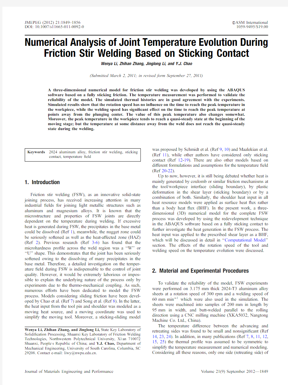
modeling.Blind holes having 1mm diameter and 2mm depth were drilled for embedding the K-type thermocouples with an outer diameter of 1mm as illustrated in Fig.1.The welding was started at a distance of 50mm away from the edge.The plunging depth of the tool shoulder was 0.35mm and the weld length was 100mm.The plunge,dwell and post-weld air-cooling times were 5.7,10,and 68s,respectively.The tool made of 1Cr18Ni9Ti austenitic steel was characterized by a non-threaded probe with a 5mm diameter and 2.5mm height as well as non-concave shoulder with a 15mm diameter.
3.Numerical Solutions
3.1Computational Model
In this study,it was assumed that the probe/workpiece and shoulder/workpiece interfaces present a fully sticking condi-tion,which means that all heat generated in the whole FSW process was attributed solely to the signi?cant plastic defor-mation in the shear layer of certain thickness.The sticking condition at the probe/workpiece interface was proposed in the literature (Ref 9,13,18).However,the results obtained in all publications have been insuf?cient to determine the condition at the shoulder/workpiece interface up to now.It was also hypothesized that the power of heat generation in the shear layer (P w )during FSW is equal to the mechanical power associated with the moving tool (P tool ):P w ?P tool ?M x tFv
eEq 1T
where M is the torque,x the rotation speed,F the tool advancing force,and m the welding speed.Cui et al.(Ref 26)found that the term associated with the tool force in Eq 1was normally less than 1%of P tool and could be ignored for estimating the total tool power.Hence,P w can be further expressed as:P w %M x
eEq 2T
Theoretically,in addition,a fully sticking condition can be used to estimate the maximum torque value (Ref 9):M ?M shoulder tM pin surface tM pin bottom
????
3
p 3
r s r s shoulder ts pin surface ts pin bottom
àáeEq 3T
where r s is the yield stress,r the distance from the calculated point to the rotating axis,and s the surface area.
The BHF in the shear layer can be obtained from Eq 1-3:
BHF ?
P w
V shear layer ????3p 3d r s r x eEq 4Twhere V shear layer is the volume of the shear layer
eV shear layer ?s shoulder ts pin surface ts pin bottom àád T;d the thick-ness of the shear layer.d =0.25mm was adopted in the sim-ulation according to (Ref 19,27).
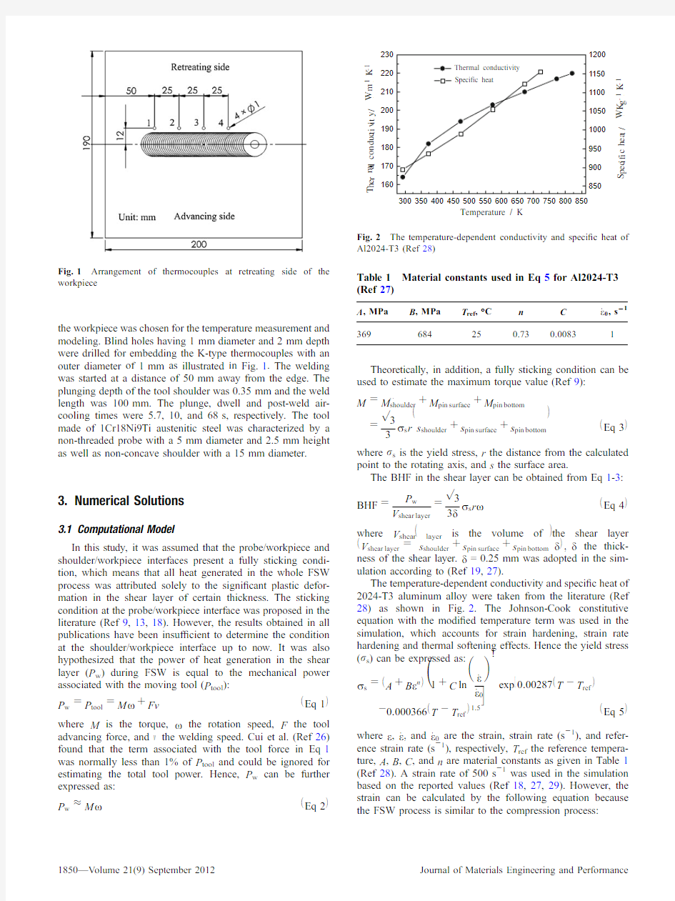
The temperature-dependent conductivity and speci?c heat of 2024-T3aluminum alloy were taken from the literature (Ref 28)as shown in Fig.2.The Johnson-Cook constitutive equation with the modi?ed temperature term was used in the simulation,which accounts for strain hardening,strain rate hardening and thermal softening effects.Hence the yield stress (r s )can be expressed as:
r s ?A tB e n
eT1tC ln _e _e 0 !
exp 0:00287T àT ref eT?à0:000366T àT ref eT1:5
i eEq 5Twhere e ,_e
;and _e 0are the strain,strain rate (s à1),and refer-ence strain rate (s à1),respectively,T ref the reference tempera-ture,A ,B ,C ,and n are material constants as given in Table 1(Ref 28).A strain rate of 500s à1was used in the simulation based on the reported values (Ref 18,27,29).However,the strain can be calculated by the following equation because the FSW process is similar to the compression
process:
Fig.1Arrangement of thermocouples at retreating side of the workpiece
Table 1Material constants used in Eq 5for Al2024-T3(Ref 27)
A ,MPa
B ,MPa T ref ,°
C n C _e 0,s 21369
684
25
0.73
0.0083
1
e ?ln d
d àvdt
eEq 6T
where v is the welding speed,dt the time increment within each time step.
Most of the heat generated at the shear layer will be transported into the workpiece while the rest enters the tool.Theoretically,the fraction of heat transported into the work-piece (f )can be estimated by the following equation based on the thermo-physical properties of the workpiece and tool:
f ??????????????????????k W q W C p W
p ?????????????????????k W q W C p W p t??????????????????
k T q T C p T p eEq 7Twhere q is the density,C p the speci?c heat and k the thermal conductivity.The subscripts W and T represent the workpiece and tool,respectively.In the present model,f is about 75%according to Eq 7.Hence,according to Eq 4and 7,the BHF from the tool shoulder can be further expressed as:
BHF ????3p 3d f gr s r x ????3p 3d f r s r x eEq 8TA non-uniform meshing was used,as shown in Fig.3,for the
workpiece to make a compromise between the computation ef?ciency and accuracy.
3.2Boundary Conditions
The heat ?ux and convection boundary conditions were introduced into the present model.The convection boundary has a convective heat transfer coef?cient of 10W m à2K à1with the ambient temperature of 20°C for the surfaces exposed to air,which was also used in the literature (Ref 27).At the plunge,dwell,and welding stages,the contact thermal con-ductivity between the backplate and workpiece was considered as a function of the temperature and pressure.It is understood that the pressure in the workpiece changes in accordance with the tool position.Hence,the contact thermal conductivity can be expressed as the function of the temperature and tool position.In this research,a simpli?ed convective heat transfer coef?cient as a function of temperature and position was applied to the bottom surface of workpiece by using the FILM subroutine available in ABAQUS.But at the cooling stage,the convective heat transfer coef?cient was only considered as a function of temperature as shown in Fig.4.Preliminary experiments were conducted to ensure excellent weld surface quality under the selected welding parameters.Hence,the temperatures of the backplate and ?xture were a little high,
and
Fig.3Full view of simulation model and meshing (just one work-piece was used)
Table 2The used welding parameters
Tool rotation speed,rpm 300,400,500,600Welding speed,mm min à1
60,70,80,90
thus the temperature in the measured workpiece was increased to about40°C before welding.Therefore,the initial temper-ature applied to the workpiece in simulations was40°C instead of the room temperature.The welding parameters used in the simulation are given in Table2.
4.Experimental Validation
Figure5shows the comparison between the calculated and experimentally recorded temperatures at the points of1and3 (see Fig.1)at300rpm and60mm minà1.It can be clearly observed that the changing trends of the calculated temperature curves are in good agreement with the measurements during the entire FSW process,though a little difference in the cooling rate presents,which implies that the cooling rate has been somewhat underestimated by the model.Further study on the contact thermal conductivity between the backplate and workpiece is essential to obtain the actual temperature?eld. Moreover,when observing the peak temperature,it is inter-esting to?nd that it is also comparable to the experiment with a maximum error of about1.8%only.In addition,it can also be seen that,both the measured and simulated peak temper-atures at points1and3are close to232and270°C,
respectively.
Fig.6Temperature contours in the retreating side at different welding times.Note that NT11means the node temperature
Nevertheless,as expected,the proposed model considering the shear layer appears to be suitable for representing the FSW process.
5.Simulated Results and Discussion
5.1Representative Temperature Evolution During FSW Figure 6shows the transient temperature distribution during the entire FSW process at 300rpm and 60mm min à1.As the tool probe plunges,the temperature in the material right under the probe rises quickly to about 194°C in 2s (Fig.6a).It can be seen from Fig.6(b)that the temperature under the tool shoulder is about 280°C after contacting with the workpiece.It is noticed from Fig.6(a)-(c)that the peak temperature presents a sharp increase from about 194to 332°C when the welding time is between 2and 15s.This temperature increase is because more heat has been produced and conducted into the workpiece after the shoulder contacts with the workpiece.Moreover,with increasing welding time,the high temperature region widens from the probe due to the heat conduction within the workpiece.From Fig.6(d)-(g),it can be discerned that the peak temperature in the workpiece is about 394°C during the entire FSW process and it presents a slight variation,which means that a thermal balance between the heat generation and dissipation has formed within and around the stirred zone at this stage and the peak temperature tends to be in a quasi-steady state.When one looks at the cooling stage (see Fig.6g-j),it is found that the peak temperature decreases sharply from 380to 252°C with increasing cooling time from 120.7to 122.7s.This means that the fast heat dissipation by heat conduction from the high temperature zone to the cold edges of the workpiece and by the convective heat transfer is relatively large at this stage.However,there is a slight variation in the temperature with increasing cooling time after about 140.7s.
5.2Effect of Rotation Speed
To study the effect of rotation speed of the tool on the FSW temperature ?eld,the rotation speed was changed from 300to 600rpm with the ?xed welding speed of 60mm min à1.
Figure7shows the effect of rotation speed on the thermal histories of points2and4.It can be seen that each point has experienced a peak temperature under different rotation speeds. Moreover,the times for reaching the peak temperatures at different rotation speeds are almost the same,but the peak values increase with increasing rotation speed.The peak value of point2is different from that of point4at the same rotation speed,which is consistent with the result in Fig.5.This means that the temperature at a place far from the weld does not reach a quasi-steady state at the welding stage though the peak temperature in the workpiece has reached a quasi-steady state (see Fig.6d-g).
Figure8shows the evolution of the maximum temperature in the workpiece with the welding time under different rotation speeds.It can be seen that with increasing welding time,the maximum temperature ascends quickly in the early stage and reaches to a temperature plateau at about18s.However,the temperature plateau is different under different rotation speeds, and that material at the same position in the workpiece will experience higher temperature at a higher rotation speed.
The effect of the rotation speed on the maximum temper-ature is shown in Fig.9(replot from Fig.8).It can be found that the temperature increment is about22°C when the rotation speed increases from300to400rpm,and the maximum temperature almost increases linearly with increasing rotation speed from300to600rpm.According to Eq8,the BHF also increases linearly with increasing rotation speed.In addition, according to Eq5,the yield stress decreases exponentially with increasing temperature.Hence,it is reasonable that the maximum temperature almost increases linearly with increasing rotation speed from300to600rpm due to the slight variation of the yield stress resulting from the increase of the temper-ature.According to Eq5and8,moreover,the BHF will increase with the augment of rotation speed while the yield stress decreases with the increase of temperature which results from the augment of BHF.This may suggest that the‘‘self-adaptive adjustment’’of material mechanical property under the applied thermal and mechanical loads is responsible for this phenomenon.This is also supported by the discussion of the relationship between tool slip and weld temperature(Ref15).
5.3Effect of Welding Speed
Figure10shows the effect of the welding speed on the temperature evolution at speci?c points in the workpiece at the rotation speed of300rpm.It can be seen from Fig.10(a)that changing welding speed has little in?uence on the time for reaching the peak temperature at point1in the vicinity of plunging center when the rotation speed is a constant,but the peak temperature decreases slightly with the increase of the
welding speed because of less heat accumulation.However,it can be found from Fig.10(b)and(c)that with increasing welding speed the times for reaching the peak temperature at points2and3become shorter and the peak values decrease slightly.According to Eq5,6,and8,with increasing welding speed the BHF will increase when other variables are constant, which means that the peak temperature in the workpiece will increase.This result seems to be inconsistent with the numerical simulation results.The reason for this is that the effect of welding time on the heat accumulation was neglected in above-mentioned analysis.
6.Conclusions
The complete welding process of FSW Al2024-T3was simulated based on a3D numerical?nite element model.The effects of the rotation and welding speeds on the temperature evolution were systematically discussed.The following con-clusions can be drawn:
(1)At the rotation speed of300rpm and welding speed of
60mm minà1,the calculated thermal histories are in agreement with the experiments and the simulated peak temperature in the workpiece is approximately394°C during the entire FSW process.
(2)The peak temperature in the workpiece near the weld
tends to be in a quasi-steady state at the beginning of the moving stage,but not at a place far from the weld.
(3)Increasing the rotation speed has no in?uence on the
time for reaching the peak temperature in the workpiece at a constant rotation speed,but the peak value gradu-ally increases with the augment of the rotation speed.
Moreover,changing welding speed has signi?cant effect on the time for reaching the peak temperature at points away from the plunging center when the welding speed is a constant and the value of this peak temperature also changes somewhat.
Acknowledgments
The authors would like to appreciate?nancial supports from the Ao-Xiang Star Project of Northwestern Polytechnical University (NPU),the Research Fund of the State Key Laboratory of Solidi?cation Processing(NPU,China)(Grant No.69-QP-2011), the Program for New Century Excellent Talents in University by the Ministry of Education of China(NECT-08-0463),and the National Natural Science Foundation of China(51005180)and the 111Project(B08040).
References
1.Y.Sato,H.Kokawa,and M.Enomoto,Microstructural Evolution of
6063Aluminum during Friction Stir Welding,Metall.Mater.Trans.A, 2000,30,p2429–2437
2.C.J.Dawes and W.M.Thomas,Friction Stir Process for Aluminum
Alloys,Weld.J.,1996,75,p41–45
3.H.Fujii,Y.F.Sun,and H.Kato,Microstructure and Mechanical
Properties of Friction Stir Welded Pure Mo Joints,Scripta Mater., 2011,64,p657–660
4.L.Fratini,G.Buffa,and R.Shivpuri,Mechanical and Metallurgical
Effects of in Process Cooling during Friction Stir Welding of AA7075-T6Butt Joints,Acta Mater.,2010,58,p2056–2067
5.H.J.Liu,H.J.Zhang,and L.Yu,Effect of Welding Speed on
Microstructures and Mechanical Properties of Underwater Friction Stir Welded2219Aluminum Alloy,Mater.Des.,2219,32,p1548–1553 6.M.Peel,A.Steuwer,M.Preuss,and P.J.Withers,Microstructure,
Mechanical Properties and Residual Stresses as a Function of Welding Speed in Aluminium AA5083Friction Stir Welds,Acta Mater.,2003, 51,p4791–4801
7.Y.Chao and X.Qi,Thermal and Thermo-Mechanical Modeling of
Friction Stir Welding of Aluminum Alloy6001-T6,J.Mater.Process.
Manuf.Sci.,1998,7,p215–233
8.M.Song and R.Kovacevic,Thermal Modeling of Friction Stir Welding
in a Moving Coordinate and Its Validation,Int.J.Mach.Tool Manuf., 2003,43,p605–615
9.H.Schmidt,J.Hattel,and J.Wert,An Analytical Model for the Heat
Generation in Friction Stir Welding,Modell.Simul.Mater.Sci.Eng., 2004,12,p143–157
10.H.Schmidt and J.Hattel,Thermal Modelling of Friction Stir Welding,
Scripta Mater.,2008,58,p332–337
11.M.Maalekian,E.Kozeschnik,H.P.Brantner,and H.Cerjak,Compar-
ative Analysis of Heat Generation in Friction Welding of Steel Bars, Acta Mater.,2008,56,p2843–2855
12.P.Ulysse,Three-Dimensional Modeling of the Friction Stir-Welding
Process,Int.J.Mach.Tool Manuf.,2002,42,p1549–1557
13.P.F.Mendez,K.E.Tello,and T.J.Lienert,Scaling of Coupled Heat
Transfer and Plastic Deformation around the Pin in Friction Stir Welding,Acta Mater.,2010,58,p6012–6026
14.M.Z.H.Khandkar and J.A.Khan,Thermal Modeling of Overlap
Friction Stir Welding for Al-alloys,J.Mater.Process.Manuf.Sci., 2001,10,p91–105
15.M.Z.H.Khandkar,J.A.Khan,and A.P.Reynolds,Prediction of
Temperature Distribution and Thermal History during Friction Stir Welding:Input Torque Based Model,Sci.Technol.Weld.Join.,2003, 8,p165–174
16.R.Nandan,G.G.Roy,and T.DebRoy,Numerical Simulation of Three-
dimensional Heat Transfer and Plastic Flow during Friction Stir Welding,Metall.Mater.Trans.A,2006,37,p1247–1259
17.R.Nandan,G.G.Roy,T.J.Lienert,and T.DebRoy,Numerical Modelling
of3D Plastic Flow and Heat Transfer during Friction Stir Welding of Stainless Steel,Sci.Technol.Weld.Join.,2006,11,p526–537
18.R.Nandan,G.G.Roy,T.J.Lienert,and T.DebRoy,Three-dimensional
Heat and Material Flow during Friction Stir Welding of Mild Steel, Acta Mater.,2007,55,p883–895
19.S.Xu,X.Deng, A.P.Reynolds,and T.U.Seidel,Finite Element
Simulation of Material Flow in Friction Stir Welding,Sci.Technol.
Weld.Join.,2001,6(3),p191–193
20.V.Soundararajan,S.Zekovic,and R.Kovacevic,Thermo-Mechanical
Model with Adaptive Boundary Conditions for Friction Stir Welding of Al6061,Int.J.Mach.Tool Manuf.,2005,45,p1577–1587
21.D.Kim,H.Badarinarayan,J.H.Kim,C.Kim,K.Okamoto,R.H.
Wagoner,and K.Chung,Numerical Simulation of Friction Stir Butt Welding Process for AA5083-H18Sheets,Eur.J.Mech.A-Solid,2010, 29,p204–215
22.F.Gemme,Y.Verreman,L.Dubourg,and M.Jahazi,Numerical
Analysis of the Dwell Phase in Friction Stir Welding and Comparison with Experimental Data,Mater.Sci.Eng.A,2010,527,p4152–4160 23.W.Tang,X.Guo,J.C.McClure,L.E.Murr,and A.Nunes,Heat Input
and Temperature Distribution in Friction Stir Welding,J.Mater.
Process.Manuf.Sci.,1998,7(2),p163–172
24.G.Buffa,J.Hua,R.Shivpuri,and L.Fratini,A Continuum Based Fem
Model for Friction Stir Welding—Model Development,Mater.Sci.
Eng.A,2006,419,p389–396
25.C.M.Chen and R.Kovacevic,Finite Element Modeling of Friction Stir
Welding—Thermal and Thermomechanical Analysis,Int.J.Mach.
Tool Manuf.,2003,43(13),p1319–1326
26.S.Cui,Z.W.Chen,and J.D.Robson,A Model Relating Tool Torque
and Its Associated Power and Speci?c Energy to Rotation and Forward Speeds during Friction Stir Welding/Processing,Int.J.Mach.Tool Manuf.,2010,50,p1023–1030
27.H.Schmidt,J.Hattel,and J.Wert,A Local Model for the Thermo-
Mechanical Conditions in Friction Stir Welding,Modell.Simul.Mater.
Sci.Eng.,2005,13,p77–93
28.H.K.Li,Q.Y.Shi,T.Li,and W.Wang,Auto-adaptive Heat Source
Model for Numerical Analysis of Friction Stir Welding,Mater.Sci.
Forum,2008,580-582,p267–27029.O.T.Midling and?.Grong,A Process Model for Friction Welding of Al-
Mg-Si Alloys and Al-SiC Metal Matrix Composites-I.Haz Temperature and Strain Rate Distribution,Acta Metall.Mater.,1994,42(5),p1595–1609