Tiger调节阀 中文彩页
- 格式:pdf
- 大小:1.95 MB
- 文档页数:21
FESTO费斯托老虎阀紧要类型和工作原理资料都有哪些优势介绍费斯托(FESTO)是一家德国的全球领先的先进为制造工业供应自动化解决方案的公司。
费斯托的智能化自动化设备被广泛应用于工业生产线,机器人和物流系统等各个领域。
其中,费斯托老虎阀是其紧要产品之一、费斯托老虎阀是一种充气掌控阀,它具有多种类型,并且其工作原理也各不相同。
在本文中,我们将探讨费斯托老虎阀的紧要类型和工作原理,并介绍它们的优势和应用场景。
费斯托老虎阀的紧要类型1. 单向掌控阀单向掌控阀是费斯托老虎阀最基本也是最常见的类型之一、这种阀门只能让气体沿着一个方向流动,并且可以掌控气体的流量和压力。
通常情况下,单向掌控阀可以用于堵塞管道上的气流或掌控气流的流量,常见的应用场景包括灌装、包装、压缩空气等。
2. 二位换向阀二位换向阀是费斯托老虎阀中比较常见的一种,它通常被用在需要掌控气流方向的场景中。
二位换向阀可以用于掌控气体的流量和压力,并将气体沿着不同的方向输送。
例如,可以使用二位换向阀来掌控该压缩空气是否流向某个气动缸或操作更换工具。
3. 定量阀定量阀可以掌控气流的量,使其与设定值相同。
它们可以在工业生产线中以确定的流量转移气体。
定量阀通常使用在需要掌控流量的环境中,比如供应空气或其它气体的流量,例如喷油系统或氧气输送。
4. 定位器定位器是一种针对气动执行器的阀门,可用于掌控执行器的位置,并确定执行器的位置是否符合预期。
定位器通常被用于需要连续定位和掌控执行器位置的场景中,例如掌控机器人的位置和姿势。
5. 检测阀检测阀是一种针对系统中气体是否流动的判定和掌控的阀门,它可以检测到系统中是否存在气流,从而进行掌控。
通常情况下,检测阀用于需要掌控气流的质量和流量的场景中,例如机器人或自动化掌控系统中。
费斯托老虎阀的工作原理和优势1. 工作原理费斯托老虎阀的工作原理基于气动掌控。
当掌控信号传达到阀门时,它将打开或关闭气体通道。
不同的掌控信号将产生不同的阀门响应,例如:•更改气体通道的方向或压力;•掌控或调整气体流量;•设置定量气流等。
tecno easy Proportional pressure regulation valve Type series PRE-U3Operating instructionsVersion 01ID no.:PS09575AVersion:01 Date:2018Table of contents1Notes about using the operating instructions (4)1.1About these instructions (4)1.2Warnings used (4)1.3Symbols (5)1.4Abbreviations (5)2Basic safety instructions (6)2.1General notes (6)2.2Intended use (6)2.3Personnel qualification (7)2.4Dangers (8)2.5Responsibility of the operator (8)3Product description (9)3.1Connections (9)3.2Technical data (11)3.3Type plate (13)4Assembly and installation (14)4.1Assembly (14)4.2Electrical installation (15)4.3Electrical connection diagram/plug assignment (15)5Start-up (16)5.1Start-up (16)6Service (17)6.1Inspection and maintenance plan (17)7Transport and storage (18)8Troubleshooting (19)9Decommissioning and disposal (20)9.1Decommissioning/dismantling (20)9.2Disposal (20)10Appendix (21)10.1Product observation (21)10.2Material defects and defects of title (21)10.3Declaration of conformity (22)1Notes about using the operating instructions1.1About these instructionsThese operating instructions describe how to work, operate, and maintain the producttecno easy. They provide important notes for safe and efficient use of the product.1.The operating instructions are part of the product. Keep the operating instructionscarefully.2.Transfer the operating instructions to any subsequent owner or user.For additional information, contact the manufacturer at the following address:HOERBIGER Flow Control GmbHSüdliche Römerstraße 1586972 AltenstadtGermanyInformation on the Internet: 1.2Warnings usedWarnings warn about dangers that can occur when handling the product. There are fourdanger levels with the following signal words:1.3SymbolsThis symbol indicates useful and important information.üThis symbol stands for a prerequisite that must be fulfilled before performing an action.ðThis symbol stands for an individual action to be performed.1.Numbers indicate several steps to be performed in an action instruction: Step 12.Step 29This symbol stands for the intermediate result of an action.9This symbol stands for the result of an entire action instruction.1.4Abbreviations2Basic safety instructions2.1General notesThe product was constructed, manufactured, and tested according to the followingstandards and safety regulations:■EMC directive 2004/108/ECFurthermore, the following harmonized standards and other standards were applied:■EN 61000-6-2 Electromagnetic compatibility (EMC); generic standard for immunityto interference; industrial sector■EN 61000-6-4 Electromagnetic compatibility (EMC); generic standard for emittedinterference; industrial sectorFor this specification, a screened connection cable must be used.The CE mark is on the valve’s type plate.2.2Intended useThe piezoelectrically-activated proportional pressure regulation valves serve to electricallycontrol pneumatic pressure. The device will only be used for compressed air andapproved gases.1.To ensure perfect, risk-free function and a long life span of the device, follow thenotes in these operating instructions and adhere to the usage conditions andpermissible data according to the data sheet and type plate.2.The usage planning and operation of the device must be done according to therecognized rules of technology.3.Prevent unintentional activations or impermissible interference by taking suitablemeasures.WARNINGPersonal injury and property damage possible■Only have settings on the valve made by authorized specialized personnel trained bythe manufacturer with suitable tools.WARNINGUse is forbidden in case of:■Use of aggressive gases that can damage the valve■Use of pneumatic variables that lie outside the area of application (see Technicaldata, page 11).2.3Personnel qualificationUnqualified personnel cannot detect risks and is therefore subject to greater dangers.1.Only commission qualified personnel with the activities described in theseinstructions.2.Make sure that the personnel adheres to the locally valid regulations and rules forsafe and danger-conscious work.The following target groups are addressed in these instructions:Trained person: A trained person is somebody who has been trained extensively by theoperator in his tasks in connection with the safe operation of the valves.Training is conducted by specialized personnel.Electrically-qualified person: An electrically-qualified person is somebody who, based on his specialized training, knowledge, and experience, as well as knowledge of theapplicable regulations, can judge and perform the work with which he is commissioned and detect possible hazards independently.Pneumatically-qualified person: A pneumatically-qualified person is somebody who, based on his specialized training, knowledge, and experience with respect to pneumaticcomponents and systems as well as knowledge of the applicable regulations, can judge and perform the work with which he is commissioned and detect possible hazards –especially with respect to interactions between pneumatic, mechanical, electrical, and control-technical components – independently.2.4DangersHere you will find information about various types of dangers and damage that can occur in connection with operation of the product.Electricity1.Only have the device connected to the power supply and control lines by anelectrically-qualified person.2.Only perform installation and maintenance work when the power is disconnected.Pressure1.Only have the device assembled by a pneumatically-qualified person.2.Only install pneumatic components when the compressed air system isdepressurized.3.During assembly and dismantling, adhere to the recognized rules of technology.4.During work on pneumatic systems, heed the special safety regulations.Operation1.Settings on the valve only by authorized personnel trained by the manufacturer withsuitable tools.2.Only use the device in industrial applications for compressed air and permissiblegases. Adhere to the working pressure according to the data sheet.3.The device is only approved for proper or intended use.4.Do not open the device.5.Do not remove type designations or seals that do not serve transport protection.6.Heed the prescribed air purity.Repair and maintenance1.Only have repair work on the valve performed by the manufacturer since only themanufacturer has the equipment for optimal adjustment after repair and cantherefore guarantee perfect function.2.Do NOT maintain the inner parts of the device.3.Send the complete valve to the manufacturer for maintenance and service.2.5Responsibility of the operatorThe assumed duties of the operator are:1.Adherence to operational safety regulations.2.Adherence to the valid national occupational safety regulations.3.Adherence to the intended use of the valve.3Product description3.1Connections1234567Fig. 1: Side view12Fig. 2: Top viewFig. 3: Single connection plateThe single connection plate with symmetrical hole pattern enables mounting turned by 180°.1 23 4 5Fig. 4: Proportional pressure regulation valve, can be mounted on single connection plate or battery strip3.2Technical dataGeneral technical data1) Flange plates with threaded connection, see accessories2) For use of other media, inquire with the manufacturer3) Only with connection plug mounted according to instructionsPneumatic characteristics1) With p1 = 10 bar and p2 = 6.3 bar, Δp = 1 bar2) With regard to end value p2max3) At ambient temperature +20 °C4) At p1max and p2min(0 bar)5) Only with target value > 0 Electric characteristics3.3Type platePMAX Sup:In:Type:F-No:Address Model Item no.Technical data4Assembly and installation4.1AssemblyDANGERMortal danger due to electrical voltage!■Switch off current before assembling and dismantling the valve.WARNINGDanger of crushing due to uncontrolled movement of the machinesPersonal injury and/or property damage possible.■Before restarting the system, take measures to prevent uncontrolled movement of themachines.■Make sure that nobody is in the danger zone.WARNINGPersonal injury or property damage due to overpressureImproperly connected or defective pneumatic connections can loosen under pressure andcause extremely severe injuries.■Before assembly and dismantling of valves, switch off compressed air.■Make sure that there is neither input nor output pressure on the valves.■Only use components that are suitable for the permissible pressure ranges (see Tech-nical data, page 11).■Proceed according to the special country-specific safety regulations.üThe pipelines and flange surfaces are free of contamination.üThe input pressure is at least 1 bar greater than the maximum required outputpressure.1.Make sure that the appropriate O-rings or seals are inserted on the valve and theconnection plate.2.Optionally mount the valve on a connection plate for the direct connection of lines oron another pneumatic amplifier stage. NOTICE! Tightening torque: 50 ±5 NcmCompromising of the valve function possible■Make sure that the ventilation connection and the pilot ventilation connection are notcovered. Back pressure on one of these connections compromises the function of thevalve.■Protect valve against excessive heat radiation.■Protect valve against adverse ambient conditions such as spray water or dirt, in orderto guarantee the protection type according to the data sheet.4.2Electrical installationDANGERMortal danger due to electrical voltage!■Only have the device connected to the power supply and control lines by a specialist.■Installation may only be done when the device is de-energized.■Secure against unintentional switching on.■Check electric cables for damage before connecting.1.For connection, use the included cable or a cable of equal quality with appropriatedevice outlet according to chapter Electrical connection diagram/plug assignment,page 15.2.Connect cable to the device outlet and tighten screws by hand. NOTICE! There may beno mechanical load on the cable.3.Read the type plate. Using the item number (identified as “F-No”), find theclassification of the device in question.4.Connect the individual wires of the cable according to the connection assignmentunder Electrical connection diagram/plug assignment, page 15.4.3Electrical connection diagram/plug assignmentPlug pin no.Fig. 5: Connection scheme1Power supply 24 V DC / 15 mA 4Target input (voltage)3GND target value and supply5Start-up5.1Start-upWARNINGDanger of crushing due to uncontrolled movement of the machinesPersonal injury and/or property damage possible.■Before restarting the system, take measures to prevent uncontrolled movement of themachines.■Make sure that nobody is in the danger zone.Faults due to electromagnetic radiation■Do not mount valve directly in the area of devices with high electromagneticradiation.■To adhere to the regulations according to EMC directive 2004/108/EC, use screenedlines.üThe power supply is switched off.üThere is no input or output pressure.1.Check proper mounting.2.Open compressed air supply.3.Switch on electric signal control.6ServiceCompromising of the valve function due to incorrect cleaning■Do not use cleansers that contain solvents for cleaning work.■No solvents or solids may penetrate the openings for ventilation and manualactivation.WARNINGPersonal injury and property damage due to improper servicingMalfunctions can results.■In case of fault, do NOT service the device.■In case of fault, shut the device down immediately.■Remove the complete valve and send it to the manufacturer's local agent forservicing.6.1Inspection and maintenance plan7Transport and storage1.Store the product in level, dry rooms that are free of dust and vibrations.2.In case of longer unpackaged storage, seal all pneumatic connections of the valvewith tape that can be removed without leaving residues.For more information, see Technical data, page 11.8Troubleshooting1.Customers and third parties should not make any changes to or perform anytroubleshooting on the device.2.Send the defective product to the manufacturer or its local representative forservicing.Decommissioning and disposal9Decommissioning and disposal9.1Decommissioning/dismantlingWARNINGRisk of injury due to pressure■Do not perform any work on the valve when it is pressurized.üThe power supply is switched off.üThere is no input or output pressure.üThe machines/systems (e.g. actuators) have been moved into a safe switch state(control positions).ðDismantle.9.2DisposalThe disposal of the packaging and used parts is the customer’s responsibility.ðDispose of the product according to the local regulations at approved collectionpoints or have removed by approved disposal companies.10Appendix10.1Product observationOur goal is continuous enhancement of our products and close cooperation with thecustomer. Please tell us about faults or problems with the valve.10.2Material defects and defects of titleThese operating instructions and technical details with respect to the specifications andfigures in these operating instructions are subject to change without notice.The company HOERBIGER Flow Control GmbH makes no quality or durability guarantees,and also no guarantees about suitability for a particular purpose. These must be agreedupon expressly in writing. Public statements, promotions, and advertising co notconstitute quality specifications for the product.The operator’s claims relating to material defects and defects of title assume that hepresses this claim in writing immediately, at the latest within two working days.HOERBIGER Flow Control GmbH is in no case responsible for damage to the productitself or consequential damages caused by the product that are caused by improperhandling of the product.Insofar as HOERBIGER Flow Control GmbH is responsible for a defect, HOERBIGER FlowControl GmbH will, at its option, provide rectification of substitute performance.Liability of HOERBIGER Flow Control GmbH – regardless of the legal justification – existsonly in case of intention or gross negligence, negligent injury of life, body, health fordefects that were fraudulently concealed or whose absence was guaranteed expressly inwriting. Furthermore, according to the product liability law for personal injury or propertydamage to privately used objects.In case of negligent injury of essential contract duties, HOERBIGER Flow Control GmbHis also liable, also in case of slight negligence, however limited to the contract-typical,foreseeable damages. Additional claims are excluded.In case individual regulations of these operating instructions, the applicable legalregulations or other instructions of HOERBIGER Flow Control GmbH are disregarded,material defects and defects of title are terminated.In particular, HOERBIGER Flow Control GmbH is not responsible for failures or faultsthat are caused by modifications by the customer or other persons. In such cases, therepair costs due will be invoiced. These will also be invoiced for the checking of thedevice if no fault could be found on the device.There are no claims to the availability of previous versions and to the ability to refitdevices delivered to the respective current series state.10.3Declaration of conformityThe current declaration of conformity is included in the scope of delivery and it can be found in the download area on the company's website:/。
FESTO费斯托老虎阀重要类型和工作原理资料都有哪些优势FESTO费斯托公司是世界领先的气动和工业自动化技术供应商之一,公司致力于供给高品质的掌控技术产品,以帮忙客户提高生产效率、优化生产过程和降低成本。
作为其产品线中的一个紧要构成部分,FESTO费斯托老虎阀(Tiger Valve)不仅广泛应用于各种工业领域,而且具有稳定牢靠、安全高效的特点,受到广阔用户的欢迎。
本文将介绍FESTO费斯托老虎阀的重要类型和工作原理,并探讨其所具有的优势。
一、FESTO费斯托老虎阀的重要类型FESTO费斯托老虎阀是一种常用的气动掌控器件,其作用是掌控气路的流量和方向。
依照不同的掌控方式和结构,老虎阀可以分为多种不同类型,包括以下几种重要类型:1. 二位二通老虎阀二位二通老虎阀是最简单的一种老虎阀,也是应用最广泛的一种。
它由一个掌控部件和一个阀芯构成,通过掌控部件的电磁力,使阀芯在两个固定位置之间切换,从而实现气路的开关。
这种老虎阀一般用于单向气路中,可以实现气路的通断和掌控气压。
2. 二位三通老虎阀二位三通老虎阀也是一种常用的老虎阀类型,它由一个掌控部件和一个三通阀芯构成。
当电磁力作用在阀芯上时,将其引导到不同的位置,使气路发生变化,达到掌控气压和方向的作用。
这种老虎阀可以用于单向气路和双向气路中,通常用于掌控液压和润滑气路。
3. 三位两通老虎阀三位两通老虎阀是一种用于单向气路的气动掌控阀门,具有三个管道和两个状态。
它通过更改空气流向而掌控气体的流动。
这种阀门由一个掌控机构和一个单向阀芯构成,适合于掌控气压和速度,常用于防暴装置和液压制动系统。
4. 三位三通老虎阀三位三通老虎阀是一种广泛用于工业自动化设备的掌控元件,重要用于掌控液压和气动设备中的气流方向。
它由一个传动机构和一个阀门构成,可以掌控两个气动执行机构的气源和排气口。
这种老虎阀具有结构紧凑、操作简便、快捷便利等优点。
二、FESTO费斯托老虎阀的工作原理FESTO费斯托老虎阀重要通过掌控电磁铁的工作状态,更改阀门内气路的流通方式,从而掌控气路的流量和方向。

Solenoid/pneumatic valves, Tiger 20002d Internet: /catalogue/...Subject to change – 2023/05Solenoid/pneumatic valves, Tiger 2000Key featuresGeneral• A complete and comprehensive range with 5/2-way and 5/3-way valves• Poppet valve for monostable func-tions or piston spool for more com-plex versions with air spring and 5/3-way valves• With flow-optimised internal func -tions for higher flow rates with the same width• Pneumatic connections G1/8, G1/4, G3/8• Diverse and flexible, side and front mounting• Pneumatic or electrical actuation • Versatile electrical connection tech-nology with F or V solenoid coil with low power consumption, can also be used with valve terminals• Functional and timeless design,enclosed front housingSolenoid coils F solenoid coilsVoltage:• 12 to 230 V DC• 12 to 240 V AC (50 to 60 Hz)Power consumption:• 4.1 to 5.5 W DC • 3.85 to 9 VA AC• For all MFH valves• Selected types conform to the ATEX Directive for potentially explosive atmospheres• Solenoid coil can be easily exchanged later• Solenoid coil not included in scope of deliveryV solenoid coils Voltage: • 24 V DCPower consumption:• 2.5 W • For all MVH valves • Low heating • Solenoid coil included in scope of deliveryManifold assembly With manifold rail PALWith manifold block PRSThe valves Tiger 2000 (without an ATEX category) can be mounted on manifold rails PAL with a common supply port or on manifold blocks PRS with a common supply port and common exhausts.The manifold rail and manifold block have 2 to 10 valve positions.H- -NoteValves for potentially explosiveatmospheres (ATEX category) are not suitable for mounting on manifold rails PAL or manifold blocks PRS.Block mounting of Tiger 2000 valves in potentially explosive atmospheres is only recommended in combination with PRS-... manifold rails.Solenoid/pneumatic valves, Tiger 2000 Product range overview3 2023/05 – Subject to change d Internet: /catalogue/...4d Internet: /catalogue/...Subject to change – 2023/05Solenoid valves, Tiger 2000Peripherals overviewMounting on manifold block14Variants MFH-5-...-BMVH-5-...-BSolenoid valves, Tiger 2000 Peripherals overview5 2023/05 – Subject to change d Internet: /catalogue/...6d Internet: /catalogue/...Subject to change – 2023/05Solenoid valves, Tiger 2000Peripherals overviewMounting on manifold rail14Variants MFH-5-...-BMVH-5-...-BSolenoid valves, Tiger 2000 Peripherals overview7 2023/05 – Subject to change d Internet: /catalogue/...Solenoid valves, Tiger 2000Type codes8d Internet: /catalogue/...Subject to change – 2023/05Solenoid valves MFH-B, Tiger 2000 Technical data – 5/2-way valves-M-Flow rate Array 750 ... 2000 l/min-P- Voltage12, 24, 42, 48 V DC24, 42, 48, 110, 230,240 V ACSets of wearing partspage 13a1)9 2023/05 – Subject to change d Internet: /catalogue/...10d Internet: /catalogue/...Subject to change – 2023/05Solenoid valves MFH-B, Tiger 2000Technical data – 5/2-way valves1)For non-reversible valves2)Corrosion resistance class CRC 1 to Festo standard FN 940070Low corrosion stress. Dry indoor application or transport and storage protection. Also applies to parts behind coverings, in the non-visible interior area, and parts which are covered in the application (e.g. drive trunnions).1)For reversible valvesMaterialsSectional view11) F solenoid coils a page 64-M-Flow rate1000 ... 2000 l/min -P- Voltage12, 24, 42, 48 V DC24, 42, 48, 110, 230,240 V AC1)ATEX valve1)Corrosion resistance class CRC 1 to Festo standard FN 940070Low corrosion stress. Dry indoor application or transport and storage protection. Also applies to parts behind coverings, in the non-visible interior area, and parts which are covered in the application (e.g. drive trunnions).1)For reversible valvesMaterialsSectional view11) F solenoid coils a page 64Technical data – 5/3-way valves -M-Flow rate1000 ... 2600 l/min-P- Voltage12, 24, 42, 48 V DC24, 42, 48, 110, 230,240 V AC1)ATEX valve1)Corrosion resistance class CRC 1 to Festo standard FN 940070Low corrosion stress. Dry indoor application or transport and storage protection. Also applies to parts behind coverings, in the non-visible interior area, and parts which are covered in the application (e.g. drive trunnions).1)With external pilot air supply and/or ATEX valves2)After long electrical actuation (> 16h), the switch-off time of 5/3-way valves can increase to max. 50 ms.3)After long electrical actuation (> 16h), the switch-off time of 5/3-way valves can increase to max. 100 ms.4)After long electrical actuation (> 16h), the switch-off time of 5/3-way valves can increase to max. 150 ms.MaterialsSectional view11) F solenoid coils a page 641) F solenoid coils a page 64-M-Flow rate750 ... 2000 l/min -P- Voltage24 V DCSets of wearing partsa page 381)Corrosion resistance class CRC 1 to Festo standard FN 940070Low corrosion stress. Dry indoor application or transport and storage protection. Also applies to parts behind coverings, in the non-visible interior area, and parts which are covered in the application (e.g. drive trunnions).1)Values for MVH-5-1/4-B-VI-XMaterialsSectional view1-M-Flow rate1000 ... 2000 l/min-P- Voltage24 V DCSets of wearing partsa page 371)Corrosion resistance class CRC 1 to Festo standard FN 940070Low corrosion stress. Dry indoor application or transport and storage protection. Also applies to parts behind coverings, in the non-visible interior area, and parts which are covered in the application (e.g. drive trunnions).MaterialsSectional view 1-M-Flow rate1000 ... 2600 l/min -P- Voltage24 V DC1)Solenoid valve MVH-5/3G-3/8-B1)Corrosion resistance class CRC 1 to Festo standard FN 940070Low corrosion stress. Dry indoor application or transport and storage protection. Also applies to parts behind coverings, in the non-visible interior area, and parts which are covered in the application (e.g. drive trunnions).1)With external pilot air2)After long electrical actuation (> 16h), the switch-off time of 5/3-way valves can increase to max. 50 ms.3)After long electrical actuation (> 16h), the switch-off time of 5/3-way valves can increase to max. 100 ms.4)After long electrical actuation (> 16h), the switch-off time of 5/3-way valves can increase to max. 150 ms.MaterialsSectional view 1Solenoid valves MVH-B, Tiger 2000 Technical data – 5/3-way valvesSolenoid valves MVH-B, Tiger 2000 Technical data – 5/3-way valvesSolenoid valves MVH-B, Tiger 2000 Technical data – 5/3-way valvesPneumatic valves, Tiger 2000Peripherals overviewMounting on manifold block Mounting on manifold rail5Pneumatic valves, Tiger 2000Type codesPneumatic valves VL, Tiger 2000 Technical data – 5/2-way valves -M-Flow rate750 ... 2000 l/minSets of wearing partsa page 49Pneumatic valves VL, Tiger 2000 Technical data – 5/2-way valves1)Corrosion resistance class CRC 1 to Festo standard FN 940070Low corrosion stress. Dry indoor application or transport and storage protection. Also applies to parts behind coverings, in the non-visible interior area, and parts which are covered in the application (e.g. drive trunnions).Pneumatic valves VL, Tiger 2000 Technical data – 5/2-way valvesPneumatic valves VL, Tiger 2000 Technical data – 5/2-way valvesPneumatic valves J, Tiger 2000Technical data – 5/2-way valves, double pilot valves-M-Flow rate1000 ... 2000 l/min1)Corrosion resistance class CRC 1 to Festo standard FN 940070Low corrosion stress. Dry indoor application or transport and storage protection. Also applies to parts behind coverings, in the non-visible interior area, and parts which are covered in the application (e.g. drive trunnions).。
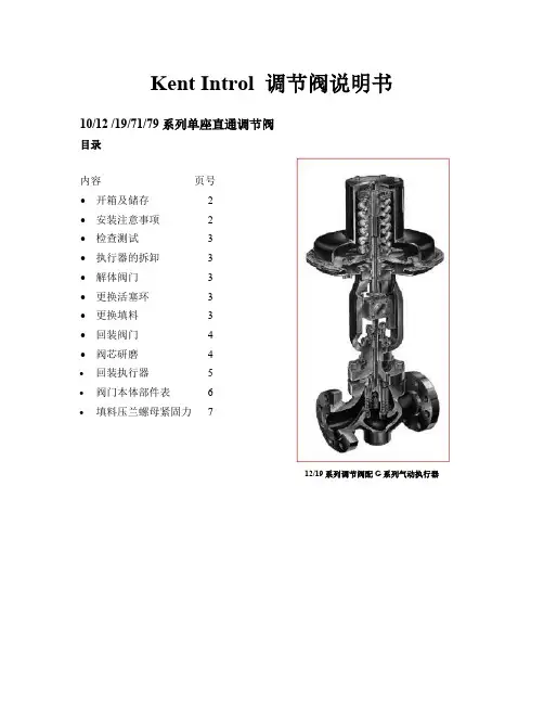
Kent Introl 调节阀说明书10/12 /19/71/79 系列单座直通调节阀目录内容页号∙开箱及储存 2∙安装注意事项 2∙检查测试 3∙执行器的拆卸 3∙解体阀门 3∙更换活塞环 3∙更换填料 3∙回装阀门 4∙阀芯研磨4∙回装执行器5∙阀门本体部件表6∙填料压兰螺母紧固力712/19系列调节阀配G系列气动执行器第一节开箱验货及贮存1.设备在包装和运输过程中有可能受到意外损伤。
当用户收到货物后,应及时开箱验货,进行外观检查,如发现阀门本体,执行器及所配仪表有外观损伤,应及时做好记录,必要时请拍下特写照片,以便供货商或货运代理迅速解决问题。
2.如果阀门包装开封后在一个月内不会被安装,请揭开法兰端口保护板涂上防护油,盖上保护板入库保存。
请做好防尘及防潮保护措施。
3.吊装运输阀门时,务必做好防止阀杆及仪表管路等部件受损的措施。
4.执行器与阀门在出厂前已做好初步调试,在非特殊情况下请不要将执行器和阀门分离,也不要拆卸任何仪表。
第二节安装注意事项:1.安装位置的选择选择直管段处安装调节阀,非特殊情况阀杆应垂直向上,执行器的上方必须预留足够的空间(最少200mm)以便检修时拆卸执行器。
特殊情况下阀门也可以竖直方向安装(执行器水平安装),但当执行器较大时,应将执行器的支架弹性支撑,必须考虑设备的振动和管道的热膨胀问题,不能硬性固定。
阀体上铸有出入口(OUT/IN)标识,同时标有介质流向箭头,必须保证出入口方向正确。
2.旁路措施如果希望调节阀在系统运行时仍能检修,请考虑采用三阀旁路措施。
3.阀门与管道的连接时的注意事项阀门两端的管道在安装阀门前应保证自然对中,附加应力不利于连接甚至损坏阀门本体。
采用法兰连接时,注意法兰螺栓紧固不要过力,否则会对阀体产生过大的附加应力甚至损坏法兰4.仪表连接如用户在定单中没有过滤减压阀,则用户必须在气动定位器前自己加装过滤减压阀。
5.填料阀门安装后,填料密封处有可能产生微量泄漏,请适当拧紧压兰螺栓,但不应过紧,否则可能因摩擦力过大造成执行器驱动阀门困难,出现卡涩现象。
••ZoneTight™, 2 vías, Ajuste a presión• Para sistemas cerrados de agua fría y caliente.• Para funciones de conmutación y control de 2 puntos en el lado del agua de unidades manejadoras de aire y sistemas de calefacción • Ensamble a presión del actuadorResumen de tiposTipoDN Z2075QPF-K20Datos técnicosDatos de funcionamientoTamaño de válvula [mm]0.75" [20]Ruta de mamagua fría o caliente, hasta 60% de glicol Rango de temp. del fluido (agua)36...212°F [2...100°C]Presión de cierre ∆ps 75 psi Differential pressure Δpmax 40psiCaracterística de flujo igual porcentajeNota sobre el ángulo de giro Margen de trabajo: 15...90°Conexión a tubería Ajuste a presiónAlturahacia arriba a horizontal (con respecto al eje)Nombre del edificio/Proyecto sin mantenimiento Patrón de flujo 2 vías Tasa de fuga0%Rango de flujo controlable 75°Cv9.8MaterialesCuerpo de la válvula Latón forjado Stem latónStem seal Tórica de EPDM Asiento PTFE, junta tórica EPDM Bolalatón cromado Suitable actuatorsNon-SpringCQB Función de falla segura eléctricaCQKB(X)Notas de seguridadADVERTENCIA: Este producto puede exponerlo al plomo que es conocido en el estado de California como causante cáncer y daños reproductivos. Para obtener más información, visite Si la temperatura excede el rango de operación de 212 °F debido a un fallo en el control de la caldera, la válvula contendrá el agua caliente de forma segura, pero la garantía del producto del fabricante quedará invalidada. La sustitución de válvulas y actuadores corre a cargo de otros.AplicaciónModo de operaciónMontaje directo y sencilloPosiciones de instalación recomendadasRequisitos de calidad del aguaServicioDirección del flujo Características del productoLas válvulas de zona QCV son adecuadas para grandes edificios comerciales donde se desea un mayor cierre y la capacidad de cambiar el flujo. Las aplicaciones comunes incluyen ventiladores unitarios, unidades fan coil, serpentines de recalentamiento VAV, carcasas de tubos de aletas, paneles radiantes y serpentines de conductos. La válvula encaja en áreas de espacio restringido y se puede ensamblar sin el uso de herramientas.La válvula de bola se ajusta mediante un actuador giratorio. El actuador giratorio se controla mediante una señal de apertura/cierre o mediante un sistema de control modulante o de 3 puntos disponible en el mercado y mueve la bola de la válvula (el dispositivo de regulación) hasta la posición preajustada por la señal de posicionamiento. La apertura de la válvula de bola se efectúa en sentido antihorario y el cierre en sentido horario.Montaje a presión sin necesidad de herramientas.El actuador puede montarse en la válvula mediante presión manual (Precaución: Únicamente pueden hacerse movimientos verticales). Las pestañas deben encajar en los agujeros de la brida.La orientación de montaje con respecto a la válvula puede seleccionarse en incrementos de 180°. (Es posible hacerlo dos veces)Notas de instalaciónLa válvula de bola se puede instalar de vertical a horizontal. La válvula de bola no puedeinstalarse en posición suspendida, es decir, con el vástago hacia abajo.Las válvulas Belimo son dispositivos de regulación. Para que las válvulas funcionencorrectamente a largo plazo, deben mantenerse libres de partículas (por ejemplo, cordones de soldadura durante los trabajos de instalación). Se recomienda la instalación de un filtro colador adecuado. No debe haber partículas de más de 0.04 "(1 mm).Las válvulas de bola y los actuadores giratorios no requieren mantenimiento.Antes de realizar cualquier trabajo de servicio en el dispositivo de control final, es esencial aislar el actuador giratorio de la fuente de alimentación (desconectando el cable eléctrico si es necesario). Todas las bombas en la parte del sistema de tuberías en cuestión también deben apagarse y las válvulas correderas adecuadas deben cerrarse (deje que todos los componentes se enfríen primero si es necesario y siempre reduzca la presión del sistema al nivel de presión ambiente).El sistema no debe volver a ponerse en servicio hasta que la válvula de bola y el actuador giratorio se hayan reensamblado correctamente de acuerdo con las instrucciones y la tubería haya sido rellenada por personal capacitado profesionalmente.El sentido del flujo es posible en ambas direcciones.Ajuste de flujo El ángulo de giro del actuador puede modificarse en incrementos de 2.5° mediante un clip. Estese utiliza para ajustar el valor kvs (flujo máximo de la válvula).Extraiga la pinza de tope y colóquela en la posición deseada.Después de cada cambio del ajuste del flujo mediante la pinza de tope, debe activarse unaadaptación en los actuadores modulantes.Dibujos dimensionalesTipo DNZ2075QPF-K20A B C D E F5.2" [133] 4.9" [125]3,4" [87] 2.8" [70]0.9" [24]0,9" [24]A B C D E F5.2" [133] 4.9" [125]3,3" [83] 2.6" [65]0.9" [24]0,9" [24]On/Off, punto flotante, sin resorte de retorno,100...240 V AC• Tensión nominal AC 100...240 V• Control On/Off (Encendido/Apagado), Punto flotante• Señal de salida (posición)Datos técnicosDatos eléctricosTensión nominal AC 100...240 V Frecuencia nominal 50/60 Hz Rango de tensión nominalAC 85...265 V Consumo de energía en funcionamiento 1 W Consumo energía en reposo 0.7 W Transformer sizing 2 VAConexión eléctrica Cable completo de 18 GA, 3 ft [1 m], con conector de conducto de 1/2"Protección de sobrecarga electrónica giro completo 0...90°Electrical Protectionlos actuadores tienen doble aislamiento Datos de funcionamientoÁngulo de giro90°Nota sobre el ángulo de giro ajustable con tope mecánico Tiempo de giro (motor)75 s / 90°Nivel de ruido, motor 35 dB(A)Indicador de posiciónindicadorDatos de seguridadFuente de suministro eléctrico UL Alimentación de clase 2Grado de protección IEC/EN IP40Grado de protección NEMA/UL NEMA 2RecintoUL Enclosure Type 2Listado de agenciascULus según UL60730-1A/-2-14, CAN/CSA E60730-1:02, CE según 2014/30/EU y 2014/35/EU; listado según UL 2043 - apto para su uso en cámaras de aire según la sección 300.22(c) del NEC y la sección 602.2 del IMC Norma de Calidad ISO 9001Temperatura ambiente2...40°CTemperatura de almacenamiento -40...176°F [-40...80°C]Humedad ambiente Máx. 95% RH, sin condensación Nombre del edificio/Proyectosin mantenimiento Peso Peso0.44 lb [0.20 kg]MaterialesMaterial de la carcasa UL94-5VAAplicaciónCaracterísticas del productoActuador ZoneTight de apertura/cierre/3 puntos sin función de protección a prueba de selección de la válvula debe hacerse de acuerdo con los parámetros de flujo y las especificaciones del sistema.El actuador se monta directamente en la válvula, sin necesidad de herramientas ni de un acoplamiento adicional.El actuador funciona en respuesta a 100...240 VAC. El ángulo de giro se puede ajustar con el tope mecánico integrado.Instalacion electricaNotas de instalaciónLos actuadores con cables de electrodomésticos están numerados.Los actuadores pueden conectarse en paralelo. El consumo eléctrico y la impedancia deentrada deben ser respetados.Los actuadores con cable plenum no tienen números; en su lugar, utilizan códigos de colores.Cumple con los requisitos de cULus sin necesidad de una conexión a tierra eléctrica.Aplique solo voltaje de línea de CA o solo voltaje UL-Clase 2 a los terminales de los interruptores auxiliares. No se permite el funcionamiento mixto o combinado de voltaje de línea / voltajeextra bajo de seguridad.¡Advertencia! ¡Componentes eléctricos con corriente!Durante la instalación, prueba, servicio y resolución de problemas de este producto, puede ser necesario trabajar con componentes eléctricos energizados. Haga que un electricista con licencia calificado u otra persona que haya recibido la capacitación adecuada en el manejo de componentes eléctricos activos realice estas tareas. No seguir todas las precauciones deseguridad eléctrica cuando se expone a componentes eléctricos energizados podría provocar la muerte o lesiones graves.Esquema de conexionado On/Off AC 110...230 VPunto flotante AC 110...230 V。
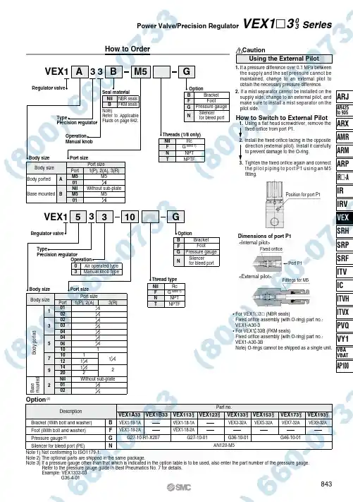
VEX1333BA BFG NM5G3VEX13BFG N10G5AB010202030404061010121420Nil0102135792B F G NVEX1A33VEX1B33VEX113VEX123VEX133VEX153VEX173VEX193VEX1-18-1A VEX1-18-2AVEX1-18-1A VEX1-18-2AVEX3-32A G27-10-R1-X207G27-10-01G36-10-01AN120-M5G46-10-01VEX5-32AVEX7-32A VEX9-32A030303030303Power Valve/Precision RegulatorHow to OrderVEX1 3 Series3843Regulator valveTypePrecision regulatorOperation Manual knobSeal material NBR sealsFKM seals Nil B Note)Refer to Applicable Fluids on page 842.Threads (1/8 only)Nil FNTRcG Note 1)NPT NPTF OptionBracket Foot Pressure gaugeSilencer for bleed portBody size Port sizeBody portedBase mounted Body size Port sizePortM501NilM5011(P), 2(A), 3(R)M5Without sub-plate M58181Regulator valveTypePrecision regulatorOperationAir operated type Manual knob type Body size Port sizeBody sizePort Port size1(P), 2(A)3(R)Thread typeNilF N TRcG Note 1)NPT NPTFOptionBracket Foot Pressure gaugeSilencer for bleed portB o d y p o r t e dB a s e m o u n t e d814141832121431Without sub-plate 1241211418141112Option (2)DescriptionBracket (With bolt and washer)Foot (With bolt and washer)Pressure gauge (3)Silencer for bleed port (PE)Part no.Note 1) Not conforming to ISO1179-1.Note 2) The optional parts are shipped in the same package.Note 3) If a pressure gauge other than that which is indicated in the option table is to be used, also enter the part number of the pressure gauge.Refer to the pressure gauge guide in Best Pneumatics No. 7 for details.Example: VEX1333-03G36-4-01CautionUsing the External Pilot1.If a pressure difference over 0.1 MPa between the supply and the set pressure cannot be maintained, change to an external pilot to obtain the necessary pressure difference.2.If a mist separator cannot be installed on the supply side, change to an external pilot, and make sure to install a mist separator on the pilot side.• For VEX1 3 (NBR seals)Fixed orifice assembly (with O-ring) part no.: VEX1-A30-3• For VEX1 33B (FKM seals)Fixed orifice assembly (with O-ring) part no.: VEX1-A30-3BNote) O-rings cannot be shipped as a single unit.How to Switch to External Piloting a flat head screwdriver, remove the fixed orifice from port P1.2.Install the fixed orifice facing in the oppositedirection (external pilot). Install it carefully to prevent damage to the O-ring.3.Tighten the fixed orifice again and connect the pilot piping to port P1 using an M5 fitting.Position for port P1Dimensions of port P1<Internal pilot><External pilot>Port P1Fixed orificeFittings for M5ARJAR425to 935ARX AMR ARM ARP IR -A IR IRVSRH SRP SRF ITVIC ITVX ITVHPVQ VY1VBA VBATAP100VEX。
阀的种类及图例在现场我们见到最多的就是阀。
汽包液位三冲量控制、锅炉的燃烧控制等,都是通过阀门开度和关度的大小来控制对象,我们通过算法的目的也是要控制阀门开度和关度的大小,从而达到自动控制。
阀门的用途是广泛的,因此它起的作用也是很大的。
例如:在发电厂中阀门能够控制锅炉和汽轮机的运转;在石油、化工生产中,阀门同样也起着控制全部生产设备和工艺流程的正常运转。
尽管如此,阀门同其它产品比较往往被人们忽视。
例如:在安装机器设备时,人们往往把重点放在主要机器设备方面,如:压缩机、高压容器、锅炉等,这些做法都会使整个生产效率降低或停产、或造成种种其它事故发生,所以我们有必要对阀门进行认识和了解。
阀门的分类阀门产品的种类繁多,说法也不完全统一,有的按用途分(如化工、石油、电站等)、有的按介质分(如水蒸汽、空气阀等)、有的按材质分(如铸铁阀、铸钢阀、锻钢阀等)、有的按连接形式分(如内螺纹、法兰阀等)、有的按温度分(如低温阀、高温阀等)。
我国目前大多数习惯是按压力和结构种类来区分。
即:按公称压力分:≤1.6MPa为低压阀、压力2.5、4.0、6.4MPa为中压阀、≥10MPa为高压阀、超过100MPa为超高压阀。
按结构种类分主要有:旋塞阀、闸阀、截止阀、球阀—用于开启或关闭管道的介质流动。
止回阀(包括底阀)—用于自动防止管道内的介质倒流。
节流阀—用于调节管道介质的流量。
蝶阀—用于开启或关闭管道内的介质。
也可作调节用。
安全阀—用于锅炉、容器设备及管道上,当介质压力趔过规定数值时,能自动排除过剩介质压力,保证生产运行安全。
减压阀—用于自动降低管道及设备内介质压力。
系使介质经过阀瓣的间隙时,产生阻力造成压力损失,达到减压目的。
疏水器—用于蒸汽管道上自动排除冷凝水,防止蒸汽损失或泄漏。
按用途和作用分类截断阀类——主要用于截断或接通介质流。
包括闸阀、截止阀、隔膜阀、球阀、旋塞阀、碟阀、柱塞阀、球塞阀、针型仪表阀等。
调节阀类——主要用于调节介质的流量、压力等。
tigercontrols执行器说明书Tiger Controls执行器是一种高性能的自动控制设备,用于执行各种工业过程中的控制任务。
该执行器具有可靠性强、使用方便、响应迅速等特点,是众多工业领域中不可或缺的设备之一、以下是有关Tiger Controls执行器的详细说明。
一、功能与特点:1. 功能:Tiger Controls执行器可以实现精确的位置控制,通过与配套的控制系统合作,可完成开关、调节、切换等各种控制任务。
它可以被广泛应用于工业自动化、机械制造、化工、电力、石油等行业中,提高生产效率和产品质量。
2.特点:- 可靠性强:Tiger Controls执行器采用先进的设计和制造技术,具有高可靠性,能够适应各种恶劣的工作环境,如高温、低温及高湿度等。
-响应迅速:该执行器采用电动机作为动力源,具有快速启动和停止的特点,能够迅速响应控制系统的指令。
- 节能高效:Tiger Controls执行器采用先进的节能技术,具有高效能和低能耗,可以降低运行成本。
-使用方便:执行器配备了用户友好的操作面板和显示屏,可通过触摸屏或按钮进行操作和状态检测,使用简便。
二、结构与类型:1. 结构:Tiger Controls执行器的主要组成部分包括驱动装置、转动机构、控制装置和电气连接部分。
这些组成部分经过精心设计,紧密地配合工作,确保了执行器的正常运行。
2. 类型:根据不同的应用需求,Tiger Controls执行器可以分为以下几种类型:-旋转执行器:主要用于控制阀门、活塞和蝶阀等的旋转角度,可实现精确的角度控制。
-线性执行器:主要用于控制线性阀门、活塞和气缸等的位置,可实现精确的位置控制。
-旋转-线性执行器:结合了旋转和线性执行器的功能,适用于一些复杂的控制任务。
三、安装与调试:1.安装:在进行安装之前,需要确保执行器的电源、信号线和控制系统的连接正确无误。
然后根据实际需求选择合适的安装位置,并确保固定牢固。
温度调节阀图片及温度调节阀分类■ 上海沃中电动温度调节阀工作原理:电动温度调节阀(电动温度控制阀),由控制阀门、执行器、传感器和毛细管等部件组成。
按用途分为加热型和冷却型。
电动温度调节阀(适用于较大口径及导热油控制),该阀最大的特点只需普通220V电源,利用被调介质自身能量,直接对蒸汽、热水、热油与气体等介质的温度实行自动调节和控制,亦可使用在防止对过热或热交换场合,电动温度控制阀结构简单,操作方便,选用调温范围广、响应时间快、密封性能可靠,并可在运行中随意进行调节,因而广泛应用于化工、石油、食品、轻纺、宾馆与饭店等部门的热水供应。
电动温度调节阀主要适用于液体、气体和蒸汽,在各种冷却系统中的温度控制。
当被控介质温度升高,控制阀门关闭(加热型);当被控介质温度升高,控制阀门开启(冷却型)。
电动温度调节阀主要特点如下:1、控制精度高,工作稳定,安全可靠。
2、感温液体膨胀均匀,比例式调节控制。
3、温度设定操作简单,调节方便。
4、体积小、重量轻,安装方便。
自力式温度调节阀工作原理:自力式温度调节阀利用液体受热膨胀及液体不可压缩的原理实现自动调节。
温度传感器内的液体膨胀是均匀的,其控制作用为比例调节。
被控介质温度变化时,传感器内的感温液体体积随着膨胀或收缩。
被控介质温度高于设定值时,感温液体膨胀,推动阀芯向下关闭阀门,减少热媒的流量;被控介质的温度低于设定值时,感温液体收缩,复位弹簧推动阀芯开启,增加热媒的流量。
自力式温度调节阀应用:自力式温度调节阀,又称温控阀、自力式温度控制阀、温度调节阀、温度控制阀。
由控制阀门和温控器组成。
按用途分为加热型和冷却型。
自力式温度调节阀主要由控制阀及温控器组成,是一种无需外来能源而依靠被控介质自身的温度变化进行自动调节的节能产品。
适用于非腐蚀性的液体、气体和蒸汽,在各种冷却系统中的温度控制。
当被控介质温度升高,控制阀门关闭(加热型);当被控介质温度升高,控制阀门开启(冷却型)自力式温度调节阀主要参数:沃中阀门温度调节阀网址:/。
tigercontrols执行器说明书第一部分:产品概述Tiger Controls执行器是一种电子继电器,用于控制各种电子设备的开关。
它采用先进的技术,具有高效、可靠和稳定的性能。
该执行器适用于各种工业和住宅应用,如自动化系统、电动机控制、照明控制等。
第二部分:产品特点1. 高效管控: Tiger Controls执行器具有高效的控制能力,能够准确、精确地实现开关控制功能。
它不仅可以实现自动控制,还可以根据具体需求进行手动控制。
2.可靠性:该执行器采用先进的电子技术,具有高度可靠性。
它可以长时间工作而不会出现故障,并且在控制过程中保持稳定运行。
3. 简单易用: Tiger Controls执行器具有简单的操作界面,用户可以轻松地完成各种设置和操作。
它还具有清晰的指示灯和显示屏,可以直观地显示当前的工作状态。
4.多功能:该执行器具有多种功能,包括定时开关、定时器和延迟操作等。
用户可以根据需求设置执行器的工作模式,并灵活地控制各种设备。
5. 兼容性: Tiger Controls执行器兼容各种不同类型的设备和控制系统。
无论是电动机、灯光、风扇还是其他电子设备,都可以与该执行器进行连接和控制。
第三部分:操作指南1. 连接设备: 首先,将Tiger Controls执行器与需要控制的设备连接。
确保连接正确,以免造成损坏或故障。
2.电源设置:接通电源并通过开关打开执行器。
在执行器工作时,请注意电源的稳定性,以免影响执行器的性能。
3.操作界面:使用执行器上的操作面板进行设置和操作。
根据需要选择相应的设置选项,并按说明进行操作。
4.定时设置:如果需要进行定时开关操作,请进入定时设置菜单,并按照提示进行设置。
确定所需的开关时间和频率,并保存设置。
5.测试和检查:在设置和操作完成后,可以进行测试和检查,以确保执行器正常工作并达到预期效果。
第四部分:注意事项1.请仔细阅读说明书并按照说明进行操作。
不正确的操作可能会造成设备故障或损坏。
A GREAT ALTERNATIVE FOR THE HEALTHY WORKFORCEThe Workrite Sierra HXL Crank is engineered to enable manual adjustability requiring minimal amounts of human force, making it a good alternative for the healthy workforce or for areas where frequent adjustments are not required.The HXL Crank adjusts from 25.5"– 43" and will accommodate the average male or female worker, making it a good solution for companies seeking limited height adjustability. It adjusts at a rate of 5.6 turns per inch even with up to 125 pounds of equipment on the worksurface.Sierra HXL Crank is available in silver with two foot design options that can be selected to build the best workcenter for each specific application.Easily raise height 1" for every 5.2 turns.ADJUSTABLE HEIGHT WORKCENTERS SIERRA HXL™ CRANKFlat Foot25.5"–43"1.44"Sierra HXL Crank Frame SetSpecifications• Frame options: 2-leg frames • 24" or 30" depths• Widths from 36" to 72" depending on shape • Finish options: silver, black, and white • Height range: 25.5" to 43" • Payload capacity: 125 pounds •Travel speed: 1 inch = 5.6 turns•• • ADJUSTABLE HEIGHT WORKCENTERSSIERRA HXL ™ CRANK FRAME SETSierra HXL Front Crank Base SetsFoot Size Model # Color Weight US $ List CAN $ List 2-Leg Worksurfaces 36" wide 24" deep SCFHXL36-F24-☐45 $974 $1,249 30" deep SCFHXL36-F30-☐48 $985 $1,263 42" wide 24" deep SCFHXL42-F24-☐45 $980 $1,256 30" deep SCFHXL42-F30-☐48 $990 $1,269 48" wide 24" deep SCFHXL48-F24-☐46 $985 $1,263 30" deep SCFHXL48-F30-☐49 $995 $1,276 54" wide 24" deep SCFHXL54-F24-☐46 $990 $1,269 30" deep SCFHXL54-F30-☐49 $1,000 $1,282 60" wide 24" deep SCFHXL60-F24-☐47 $995 $1,276 30" deep SCFHXL60-F30-☐50 $1,005 $1,288 66" wide 24" deep SCFHXL66-F24-☐47 $1,000 $1,282 30" deep SCFHXL66-F30-☐50 $1,010 $1,295 72" wide24" deep SCFHXL72-F24-☐48 $1,005 $1,288 30" deepSCFHXL72-F30-☐51$1,016$1,303Frame Set colors: S :Silver, B :Black, W :WhiteSierra HXL T op Crank Base Sets2-Leg Worksurfaces 42" wide 24" deep SCTHXL42-F24-☐45 $980 $1,256 30" deep SCTHXL42-F30-☐48 $990 $1,269 48" wide 24" deep SCTHXL48-F24-☐45 $985 $1,263 30" deep SCTHXL48-F30-☐49 $995 $1,276 54" wide24" deep SCTHXL54-F24-☐46 $990 $1,269 30" deepSCTHXL54-F30-☐49$1,000$1,282Frame Set colors: S :Silver, B :Black, W:WhiteProducts listed on this page are available through GSA ContractGS-28F-0030S SIN #711-2 (Schedule 71)ADJUSTABLE HEIGHT WORKCENTERSSIERRA HXL ™ CRANK FRAME SETSierra HXL Accessories & Replacement Parts WorksurfaceDepth Model #Weight US $ List CAN $ ListFlat Foot Kit Reinforced steel construction for added stabilitySold as a pair for a single workstation24"FFK24-❒15$79 $10130"FFK30-❒18$90 $115Dual Depth FFK2430-❒17$85 $109Foot colors: S:Silver, B:Black, W:WhiteFour casters required for 2-leg work centers, fivecasters required for 3-leg work centersPremium PolyurethaneCastersCompatible with carpet and hard flooringLocking casters with smooth rolling 1"W × 3"Htranslucent polyurethane wheelsCasters raise work centers by 3.5"Use with all Styled Foot and Flat Foot Kits (notavailable on Cascade Work centers)Four casters for 2-leg work centers, 400 lb. grossload capacityFive casters for 3-leg work centers, 500 lb. grossload capacity4ACC-CASTER-4PK3IN-CP2$153$1965ACC-CASTER-5PK3IN-CP2$184$236 SIERRA HXL CRANK FRAME SETLaminate Price Tier 1White* SW811SD Folkstone Gray*SG241SDSlate*SG228SDHardrock MapleWM791SDMillwork CherryWC431SDFormal MahoganyWY031SDWalnut GroveWW050SDLaminate Price Tier 2078506007937380799238079253807054600798938Shadow Zephyr*0485760Misted Zephyr*0484360 Laminate Price Tier 3Grey Elm8201K12Fawn Cypress8208K16Veranda Teak8209K28Phantom Cocoa8213K28Studio Teak7960K18Phantom Charcoal8214K28Skyline Walnut7964K12Walnut Heights7965K12Figured Mahogany7040K78Black Velvet*1550531STANDARD LAMINATE AND EDGEBAND COLOR SELECTIONSApplies to: Sit-Stand Desk Worksurfaces, Sonoma Table Worksurfaces, Laminated Modesty Panels, Laminated Mobile &Hanging PedestalsWorkrite's standard laminate selections includes many popular colors from Pionite and Wilsonart. Starting with our Tier 1 selection for greatest value, through our premium Tier 2 wood grains and patterns, ending with our Tier 3 embossed and special finishes round out our offering. Our tops feature color coordinated matching 3 mm edgeband. For more accurate color selection we recommend reviewing our laminate sample chain when making selections.Note: Due to printing limitations, these colorsare not guaranteed to be accurately reproduced.For best results order actual Laminate MaterialSamples by calling (800) 959-9675.*These laminates are not available for mobile or hanging pedestal collectionSPECIAL ORDER LAMINATESWorkrite has access to many laminate manufacturers. We can quote special order laminates on request from Wilsonart, Pionite, Nevamar, Formica, and Abet Laminati. If you don't see the brand, give us a call.Please note for special order laminate colors: based on laminate brand, color requested, and specific color matching edgeband requirements, minimum order requirements and special order upcharges may apply.Flexible Solutions for the Ergonomic Workplace.©2019 Workrite Ergonomics, 2277 Pine View Way, Suite 100, Petaluma, CA 94954 800.959.9675WORKSURFACES0919 Subject to change without notice.ExploreLaunch website。
T iger Controls E-mail: sales@北京泰德尔自控设备有限公司(Tiger Controls)是中央空调自控产品(HVAC)的专业制造商,公司主要生产:电动风阀驱动器、电动球阀、电动调节阀及驱动器、电动蝶阀、动态平衡类阀门及部分控制器、传感器,产品主要应用在中央空调自控行业(HVAC)、城市供暖、热交换、电厂和石油化工等相关行业。
公司2009年投资在辽宁绥中滨海经济区兴建“泰德尔工业园”,工业园占地60亩,建筑面积约23000m 2,目前规划生产能力:电动风阀驱动器50万套/年,电动调节阀及驱动器15万套/年,工业园2010年底正式投入使用,建成后将是集设计研发、物料采购仓储、生产、检验为一体的HVAC产品现代化生产基地。
公司简介:1国内销售网络除北京总公司外还在上海、深圳、青岛、武汉和沈阳等地建立销售办事处,形成了覆盖全国主要城市的售前/售后服务网络,为代理商及客户提供高品质和高效率的服务。
海外销售区域主要面向北美、欧洲和东南亚,目前已经建立了稳定的销售网络,产品在30多个国家的制冷和供热领域得到了成功的应用。
泰德尔自控拥有多年的行业经验和产品研发能力,我们把“引领技术发展,达到质量零缺陷”作为公司发展的基础,泰德尔人对客户有一个承诺:每年在研发新产品的同时均会对原有产品进行升级改进,保持技术上的领导地位。
泰德尔人拥有一个共同的目标,就是通过不懈的努力最终将Tiger Controls 塑造成HVAC领域的世界一流品牌。
2T iger Controls E-mail: sales@1.我有LED 数字显示窗口,这是我的一大亮点。
同类产品都不会说话,可我偏偏要说,而且要尽职尽责的告诉用户:我现在的运行状态是否按照控制信号要求运行。
如果我的身体不舒服,我还可以通过显示窗口告诉用户:快让“医护”人员来帮我!2.只需按住红色按钮三秒钟,我就会自动辨识和记忆阀体行程。
调试后的精度由软件保证,排除了人为因素,做到了“傻瓜”式操作,相信您一定会喜欢像上我这样的“傻瓜”!3.我还能够听懂多种语言,下列四种输入/输出信号:0(2)~10VDC、0(4)~20mA信号我都能听懂,只要打开红色前盖拨动拨码开关,就可以让我在以上四种信号之间自由转换。
4.独特的电路板与机械机构分离设计,能够让我能够有效的防御灰尘。
5.专业的弹簧限力机构+微动开关设计理念,会全程呵护我的安全,让我全行程运行安全无忧。
6.轻便快捷的手动轮设计,能够让我在没有电源的情况下轻松的实现阀门的开/关。
7.我与阀体的安装及拆卸仅需一个小小的“六角扳手”,就能可靠、便捷的完成。
8.坚固轻便的压铸铝支架是我的骨骼,让我能够在各种恶劣的环境中保持稳定工作。
9.稳重的外观和颜色设计,让用户第一次见到就会恋上我!直行程电动驱动器 特点介绍3 E-mail: sales@Tiger Controls24: 表示24VAC 220: 表示220VAC型号中24: 表示24VAC 220: 表示220VAC直行程电动驱动器 目录1. 驱动器额定输出力量 1800: 1800N3000: 3000N 5000: 5000N 16000:16000N 2. X: 比例调节型 D: 三位浮点型 3.工作电压24: 24VAC 220:220VAC 4. S:含手动装置 5 . 辅助功能(选配)F1: 10K 电阻反馈功能 F2: 极限位置干节点反馈功能 6. .12: 新款备注:上表中部分驱动器可根据需要增加F1:10K电阻反馈功能和F2:极限位置干节点反馈功能4T iger Controls E-mail: sales@500N / 1000N直行程电动驱动器产品型号说明:1. 驱动器额定输出力量 500: 500N 1000: 1000N2. X:比例调节型 D:三位浮点型3.工作电压24:24VAC 220:220VAC 4. S:含手动装置 5 . 辅助功能(选配)F1: 10K 电阻反馈功能 F2: 极限位置干接点反馈功能 6. .12: 新款5 E-mail: sales@Tiger Controls1800N / 3000N直行程电动驱动器产品型号说明:1. 驱动器额定输出力量 1800: 1800N 3000: 3000N2. X:比例调节型 D:三位浮点型3.工作电压24:24VAC 220:220VAC 4. S:含手动装置 5 . 辅助功能(选配)F1: 10K 电阻反馈功能 F2: 极限位置干接点反馈功能 6. .12: 新款6T iger Controls E-mail: sales@5000N 直行程电动驱动器(超长寿命型——可达50万次开闭次数)产品型号说明: 1. 驱动器额定输出力量 5000: 5000N 2. X:比例调节型 D:三位浮点型 3.工作电压 24:24VAC220:220VAC 4. S:含手动装置5 . 辅助功能(选配)F1: 2K 电阻反馈功能F2: 极限位置干接点反馈功能 6. .12: 新款7 E-mail: sales@Tiger Controls16000N直行程电动驱动器产品型号说明: 1. 驱动器额定输出力量 16000: 16000N 2. X:比例调节型 D:三位浮点型 3.工作电压 24:24VAC220:220VAC 4. S:含手动装置5 . 辅助功能(选配)F1: 2K 电阻反馈功能F2: 极限位置干接点反馈功能 6. .12: 新款 8T iger Controls E-mail: sales@1. 我,口径范围大:DN15~DN400: 法兰铸钢阀体DN15~DN80: 内螺纹铸钢阀体2. 高关断压差及低泄露率3. 高品质的材料阀体:铸钢,阀杆和阀杆:不锈钢4. 使用寿命长高达10万次以上的使用寿命,保证阀体在现场的长寿命。
5. 阀体材料和铸造工艺Tiger Controls 采用的是铸钢材料WCB,在铸造工艺上采用的是精密铸造工艺。
模具为金属模具,这种铸造工艺的成本虽然高于普通铸造工艺,但铸件密度高,沙眼现象明显降低,铸件外观也明显改善,完全符合用户的高标准需求。
6. 阀体外观设计外型设计符合欧美主流直行程座阀的设计风格,采用“S型”阀体流线型设计风格,从外观上即可看出我的流道形状,这种颇具肌肉感的设计风格让我充满自信。
7. 阀体表面处理表面采用亚光烤漆工艺,黑色的外衣使我看上去更加尊贵。
8. V型密封圈+弹簧自动补偿由于密封圈的形状是V型,在受到弹簧压力的情况下呈现内孔收缩、外圆膨胀的效果,对阀杆部分的密封起到了重要的作用。
Tiger Controls 不仅仅设计了V型密封圈+弹簧自动补偿磨损的结构,而且采用了一种快捷更换的密封圈设计方案,使得在特殊情况下密封圈的更好变得相当方便,这一点,谁用谁知道!直行程阀体 特点介绍9 E-mail: sales@Tiger Controls冷/热水阀体介质温度: -25~130℃产品型号说明:1. F:法兰阀门2. ***:阀门口径3. 适用介质V: 水 -25℃-130℃ S: 蒸汽 2℃-180℃ A: 蒸汽 2℃-220℃ P: 蒸汽 2℃-450℃4. 阀体材质 G:铸钢 5. 承压C: PN16 D: PN256. .12: 新款直行程阀体 目录蒸汽阀介质温度: 2~180℃, 2~220℃, 2~450℃备注:***表示阀门口径备注:***表示阀门口径10T iger Controls E-mail: sales@法兰铸钢阀体备注:二通法兰蒸汽阀、超高温阀参数请参照网页:.产品型号说明:1. F:法兰阀门2. ***:阀门口径3. 适用介质:V: 水 -25℃-130℃; S: 蒸汽 2℃-180℃; A: 蒸汽 2℃-220℃ ;P: 蒸汽 2℃-450℃4. 阀体材质: G:铸钢 5. 承压C: PN16; D: PN25 6. .12: 新款最大关闭压差 △Ps: 阀体与驱动器配合后最大能够关闭的水压差值。
最大允许压差 △Pmax:当阀门全开时,驱动器可以正常关闭阀门,且阀门没有明显噪音的情况下,阀门前后两端允许的最大压差值。
11 E-mail: sales@Tiger Controls备注:H-1: 与500N 、1000N 不带手动驱动器连接; H-2: 与500N 、1000N 带手动驱动器连接 H-3: 与1800N 、3000N 不带手动驱动器连接; H-4: 与1800N 、3000N 带手动驱动器连接 H-5: 与5000N 带手动驱动器连接; H-6: 与16000N 带手动驱动器连接12二通法兰铸钢尺寸备注: 1. 如介质为乙二醇等低温介质,请选用附件:THOT-1点加热套,保护阀杆处不结冰。
13T iger Controls E-mail: sales@ E-mail: sales@T iger Controls备注:1.如蒸汽阀需要断电复位功能,请增加附件:断电自复位控制器TUPS-24系列,该产品可以在系统断电的情况下为阀门供电并提供调节阀关闭的控制信号。
具体参数请参照本公司网站中详细资料: ,或向当地经销商索取。
141.如蒸汽阀需要断电复位功能,请增加附件:断电自复位控制器TUPS-24系列,该产品可以在系统断电的情况下为阀门供电并提供调节阀关闭的控制信号。
具体参数请参照本公司网站中详细资料:,或向当地经销商索取。
15T iger Controls E-mail: sales@ E-mail: sales@T iger Controls1.阀板采用“无销”设计,阀板与阀轴配合部分为方孔,不存在因传统圆阀轴的销子腐蚀造成的故障,这种设计保证了阀轴不与介质接触,保证了阀体整机的高寿命。
2.阀座密封圈采用进口材料,抗老化性能出色,保证了密封圈的弹性,蝶阀关闭后泄露量非常小。
3.阀板表面有尼龙镀层,进一步提高了阀板的耐腐蚀性。
4.阀轴阻力非常小,驱动器转动轻松灵活。
5.阀体法兰符合国标、美标和欧标的法兰标准。
6.阀体可以360度任意角度安装,如阀体表面易产生冷凝水则不建议驱动器向下安装。
7.蝶阀驱动器标准配置带手动和旋转角度显示窗口,给使用带来了方便。
8.接线盒与机械传动部件采用分离设计,降低了用户在使用中误操作的可能性。
9.蝶阀驱动器与阀体连接及拆卸都很方便,无需专用工具。
10.产品外形设计轻巧,模具制作工艺精细。
电动蝶阀 特点介绍16T iger Controls E-mail: sales@电动蝶阀阀体型号说明:1. T:泰德尔自控 2. DHJ1: -10...+80℃ 对夹式阀板材料为球墨铸铁+尼龙镀层 DHJ2: -10...+130℃ 对夹式阀板材料为不锈钢304 3. 阀体口径 例如:50表示DN50 电动蝶阀驱动器型号说明:1. T: 泰德尔自控 2. BV:蝶阀 3. 额定输出力矩 例如:50表示50N.M 4.D:开关型DF1:开关型带1K电阻反馈DF2:开关型带2个无源干节点反馈卡X.V:比例调节型(输入输出信号为0~10VDC) X.MA:比例调节型(输入输出信号为4~20mA)电动蝶阀备注:上选修表中开关型驱动器未带任何反馈功能,如需增加1K电阻反馈请在驱动器型号末尾增加F1,如需增加2个无源干节点反馈请在驱动器型号末尾增加F2具体参数请参照本公司网站中详细资料:.17项目名称:海南三亚亚龙湾冰蓄冷区域供冷项目(冰蓄冷——国家示范项目) 应用产品:电动调节阀部 分 工 程 案 例北京地区:银泰中心(空调控制阀)北京南站(加湿控制阀)CCTV大楼(平衡阀)奥运村太阳能节能项目(空调控制阀)北京地铁1、2号线改造(空调控制阀)国家外交部空调自控改造(空调控制阀)北京市望京摩托罗拉科技园(空调控制阀)中轻太阳能电池责任有限公司(空调控制阀)北京良乡华冠超市(空调控制阀)大兴区影剧院(空调控制阀)北京幸福家园会所(空调控制阀)北京门头沟林美宾馆(空调控制阀)北京科星阳光太阳能技术研究所(加湿控制阀)北京佑安医院(手术室洁净空调控制阀)中日友好医院(手术室洁净空调控制阀)三零六医院(空调控制阀)北京协和制药厂(空调控制阀)北京同仁堂(工艺空调控制阀)崇文区社区服务中心(供热控制阀)北京安贞华联商场(供热控制阀)中科院蔬菜研究院(供热控制阀)中科院动物研究所(供热控制阀)北京航天总院(供热控制阀)北京望京购物商业城(供热控制阀)北京铁路局(供热控制阀)北京丰台动车维修中心(供热控制阀)人民大学(供热控制阀)首都经贸大学(供热控制阀)北京交通大学(供热控制阀)北京林业大学(供热控制阀)北京体育大学(供热控制阀)外经贸部干部管理学院(供热控制阀)北京航空航天大学(供热控制阀)北方工业大学教学楼(供热控制阀)北京外国语学院(供热控制阀)首都医科大学(供热控制阀)中国音乐学院(供热控制阀)北京清华大学汽车系(供热控制阀)通州第二外语学院(供热控制阀)北京第二外语学院(供热控制阀)北方交通大学光波楼(供热控制阀)北方交通大学宿舍楼(供热控制阀)北京工业大学第三实验楼(供热控制阀)中国传媒大学锅炉节能系统改造(供热控制阀)中国人民解放军95989部队(供热控制阀)北京军区总后勤部201所(供热控制阀)北京望京医院(供热控制阀)北京武警总医院(供热控制阀)北京吉普有限公司(供热控制阀)北京宣武区环卫局(供热控制阀)北京电力科技研究院(供热控制阀)北京卫生局党校(供热控制阀)18 E-mail: sales@T iger Controls部 分 工 程 案 例华东区:花旗银行大厦(空调控制阀)ABB高压继电器有限公司(空调控制阀)上海华普汽车厂(空调控制阀)大陆泰密克电子(上海)有限公司(空调控制阀)上海第一人民医院松江分院(空调控制阀)上海圣和圣广场(空调控制阀)乐购宝山三门店(空调控制阀)上海汽车齿轮变速箱厂(空调控制阀)上汽集团仪征工厂(空调控制阀)上海影城(空调控制阀)上海新纺城(空调控制阀)上海贝岭股份有限公司(空调控制阀)瑞金医院高干病房手术室(加湿控制阀)拜尔药业(上海)有限公司(空调控制阀)博地精品酒店(空调控制阀)扬州市博物馆(空调控制阀)扬州市农村商业银行(空调控制阀)扬州淮左大酒店(空调控制阀)江苏宝应范水骏升(空调控制阀)江苏江南高纤有限公司(空调控制阀)江苏贺立氏股份有限公司(空调控制阀)南京悦榕温泉(空调控制阀)南京福特汽车(空调控制阀)南汽名爵(空调控制阀)康宁光纤股份有限公司(空调控制阀)西南区:成都进出口加工区芯片厂(空调控制阀)东方电气集团东方汽轮机厂(空调控制阀)成都生物制品研究所(空调控制阀)四川雅安三九药业股份有限公司(空调控制阀)中住光纤有限公司(空调控制阀)南充天蔡乳业有限公司(空调控制阀)四川地奥集团制药有限公司(空调控制阀)成都妇幼儿童医院(空调控制阀)四川省人民医院(空调控制阀)重庆龙湖西城天街(空调控制阀)重庆地税局(空调控制阀)重庆惠普工厂(空调控制阀)重庆东风小康工厂(空调控制阀)重庆长安铃木工厂(空调控制阀)重庆川仪厂(空调控制阀)重庆龙湖水晶城(空调控制阀)武汉民生大厦(空调控制阀)武汉钢铁公司焦化厂(空调控制阀)武汉地税局办公大楼(空调控制阀)武汉本位餐厅(空调控制阀)武汉重型机械厂(空调控制阀)湖北农业银行培训中心图书馆(空调控制阀)湖北农业银行培训中心办公楼(空调控制阀)湖北枝江奥美医疗工厂(空调控制阀)衡阳港通油脂(过程控制阀)项目名称:北京同仁堂制药厂(工艺空调) 应用产品:电动调节阀19T iger Controls E-mail: sales@ E-mail: sales@Tiger Controls项目名称:深圳机场信息指挥大厦、新候机楼 应用产品:电动调节阀部 分 工 程 案 例华南区:深圳机场信息指挥大厦(空调控制阀)深圳机场候机楼(空调控制阀)深圳华侨城海景酒店(空调控制阀)深圳荣超集团海滨广场(空调控制阀)深圳市凯宾斯基酒店(空调控制阀)深圳市中医院(空调控制阀)深圳报业集团(空调控制阀)深圳比亚迪工厂(空调控制阀)深圳市比克电池有限公司(空调控制阀)深圳中兴通讯股份有限公司(空调控制阀)中国长城计算机集团(空调控制阀)深圳立健药业有限公司(空调控制阀)东莞嘉辉豪庭(空调控制阀)南方李锦记营养保健品有限公司湛江红海油脂(过程控制阀)东莞盛源油脂(过程控制阀)厦门大学(空调控制阀)来奇偏光科技(厦门)有限公司(空调控制阀)三箭电子(厦门)有限公司(空调控制阀)广东宝丹制药有限公司(空调控制阀)广东立国制药有限公司(空调控制阀)广州市白云宾馆(空调控制阀)20T iger Controls E-mail: sales@ 东北区:沈阳宝马工厂(空调控制阀)沈阳乐购于洪店(空调控制阀)大连毅腾建材市场(空调控制阀)大连夏丽高尔夫俱尔部(空调控制阀)大连沙河口区公安局(空调控制阀)大连北市车城(空调控制阀)大连北市万盛购物广场(空调控制阀)大连职业技术学院(空调控制阀)大连锦绣大厦(空调控制阀)大连双D港管委会办分楼(空调控制阀)大连西雅图海洋之星(空调控制阀)大连李官新龙门温风吕温泉酒店(空调控制阀)长春一汽大众(空调控制阀)大连汉信生物(空调控制阀)辽宁抚顺石化(空调控制阀)大连空军航天活动中心(供热控制阀)双鸭山城市供暖改造(供热控制阀)吉林白山弘翔热力公司(供热控制阀)长春大唐热力有限公司(供热控制阀)通辽热力有限公司(供热控制阀)黑龙江佳木斯东方纸业(供热控制阀)吉林省吉林市一汽轻型汽车(空调控制阀)山东及其他省份:东营天东生化工业有限公司(空调控制阀)山东银河德普胶带有限公司(空调控制阀)山东省济南市平阴县伊利牛奶工艺厂房(空调控制阀)山东地区北汽福田(空调控制阀)山东东阿阿胶股份有限公司(空调控制阀)烟台-大连轮渡楼(空调控制阀)烟台市公安局(空调控制阀)青岛市青医附院(空调控制阀)山东科技大学(供热控制阀)河北省定州市伊利牛奶工艺厂房(空调控制阀)河北省沧州华峰热电有限公司(空调控制阀)内蒙古海拉尔金新化工厂(供热控制阀)宝洁有限公司天津分公司(加湿控制阀)天津三星电子(加湿控制阀)安徽省芜湖市医院(空调控制阀)安徽省滁州市安兴环保彩纤有限公司(空调控制阀)贵州省贵阳市贵定烟草有限公司(空调控制阀)西安第四军医大学消化楼(空调控制阀)西安曲江会展中心(空调控制阀)西安东关人人乐超市(空调控制阀)西安高新第四换热站(供热控制阀)西安西京医院换热站(供热控制阀)西安西飞换热站(供热控制阀)部 分 工 程 案 例项目名称:沈阳宝马工厂 应用产品:电动调节阀21。