jtag的经典例子,verilog
- 格式:doc
- 大小:94.50 KB
- 文档页数:42
⾃⼰整理的:学习verilogDHL问题笔记——Quartus常见错误我初学verilog语⾔,很多细节都没注意,按着⾃⼰的思想就写了,编译的时候才发现各种问题。
这些都是我在学习中遇到的问题,还是很常见的。
1.Error (10028): Can't resolve multiple constant drivers for net ……解析:不能在两个以上always内对同⼀变量赋值,这个细节⼀般看书看资料会看到,但是编程时,就是没想到。
2.Error (10158): Verilog HDL Module Declaration error at clkseg.v(1): port "XXXX" is not declared as port解析:⼤意了,端⼝类型还没定义啊!3.Error (10110): variable "en" has mixed blocking and nonblocking Procedural Assignments -- must be all blocking or all nonblocking assignments解析:en在程序中有时⽤⾮阻塞赋值,有时⽤阻塞赋值,这是禁⽌的。
在初学的时候,可能分得不是很清楚,所以在检查时,⼀定要⼀步步观察慢慢来。
4.Error (10161): Verilog HDL error at clkseg.v(36): object "count" is not declared解析:这个错误应该很明显啦,只要能读得懂。
5.Error (10170): Verilog HDL syntax error at clkseg.v(37) near text "***"; expecting ";"解析:意思应该也很简单,就是检查的时候要细⼼点。
jtag工作原理详解JTAG(Joint Test Action Group)是一种用于测试和调试电子设备的标准接口协议。
它提供了一种简单而有效的方法,可以对集成电路(IC)进行测试、调试和编程。
本文将详细介绍JTAG工作原理,包括其基本原理、信号线定义、时序和应用示例。
一、基本原理JTAG工作原理基于一种称为“串行扫描链”的技术。
该技术通过在芯片上添加一组可编程逻辑电路,将芯片内部的各个功能模块连接起来,形成一个长链。
这个链可以通过JTAG接口与外部设备进行通信。
二、信号线定义JTAG接口由四根主要的信号线组成,分别是TCK、TMS、TDI和TDO。
1. TCK(Test Clock):测试时钟信号,用于同步数据传输。
2. TMS(Test Mode Select):测试模式选择信号,用于控制JTAG状态机。
3. TDI(Test Data Input):测试数据输入信号,用于向芯片发送测试数据。
4. TDO(Test Data Output):测试数据输出信号,用于从芯片读取测试数据。
三、时序JTAG的时序是由JTAG状态机控制的。
JTAG状态机有四种状态,分别是Test-Logic-Reset(TLR)、Run-Test/Idle(RTI)、Select-DR-Scan(SDR)和Select-IR-Scan(SIR)。
1. TLR状态:在此状态下,芯片的所有逻辑电路都将被复位,并将扫描链的状态重置为初始状态。
2. RTI状态:在此状态下,芯片处于正常工作状态,可以执行正常的操作。
3. SDR状态:在此状态下,可以对芯片的数据寄存器进行扫描操作。
4. SIR状态:在此状态下,可以对芯片的指令寄存器进行扫描操作。
四、应用示例JTAG广泛应用于各种电子设备的测试和调试中。
以下是一个应用示例,以展示JTAG在芯片测试中的应用。
假设我们有一个芯片,其中包含一个8位的数据寄存器和一个8位的控制寄存器。
Verilog的135个经典设计实例1、立即数放大器:立即数放大器是一种用于将输入电平放大到更高电平的电路,它可以实现任意输入到输出的映射,并且可以在Verilog中使用。
立即数放大器的Verilog实现如下:module immedamp(in, out);input in;output out;reg [3:0] immed;assign out = immed[3];begincase (in)4'b0000: immed = 4'b1000;4'b0001: immed = 4'b1001;4'b0010: immed = 4'b1010;4'b0011: immed = 4'b1011;4'b0100: immed = 4'b1100;4'b0101: immed = 4'b1101;4'b0110: immed = 4'b1110;4'b0111: immed = 4'b1111;4'b1000: immed = 4'b1000;4'b1001: immed = 4'b1001;4'b1010: immed = 4'b1010;4'b1011: immed = 4'b1011;4'b1100: immed = 4'b1100;4'b1101: immed = 4'b1101;4'b1110: immed = 4'b1110;4'b1111: immed = 4'b1111;endcaseendendmodule2、多路复用器:多路复用器是一种用于将多个输入选择转换为单个输出的电路,它可以实现由多种方式选择的输出,并可以使用Verilog实现。
verilog hdl语言100例详解Verilog HDL语言是一种硬件描述语言,用于描述数字电路和系统的行为和结构。
它是硬件设计工程师在数字电路设计中的重要工具。
本文将介绍100个例子,详细解释Verilog HDL语言的应用。
1. 基本门电路:Verilog HDL可以用于描述基本门电路,如与门、或门、非门等。
例如,下面是一个描述与门电路的Verilog HDL代码:```verilogmodule and_gate(input a, input b, output y);assign y = a & b;endmodule```2. 多路选择器:Verilog HDL也可以用于描述多路选择器。
例如,下面是一个描述2:1多路选择器的Verilog HDL代码:```verilogmodule mux_2to1(input a, input b, input sel, output y);assign y = sel ? b : a;endmodule```3. 寄存器:Verilog HDL可以用于描述寄存器。
例如,下面是一个描述8位寄存器的Verilog HDL代码:```verilogmodule register_8bit(input [7:0] d, input clk, input reset, output reg [7:0] q);always @(posedge clk or posedge reset)if (reset)q <= 0;elseq <= d;endmodule```4. 计数器:Verilog HDL可以用于描述计数器。
例如,下面是一个描述8位计数器的Verilog HDL代码:```verilogmodule counter_8bit(input clk, input reset, output reg [7:0] count);always @(posedge clk or posedge reset)if (reset)count <= 0;elsecount <= count + 1;endmodule```5. 加法器:Verilog HDL可以用于描述加法器。
jtag工作原理详解JTAG(Joint Test Action Group)是一种用于测试和调试集成电路的标准接口。
它提供了一种通用的方法,使得在生产过程中可以对芯片进行测试和调试,以确保其正常工作。
本文将详细介绍JTAG的工作原理,包括其基本原理、信号传输方式、测试模式和应用案例等方面。
一、JTAG的基本原理JTAG是一种串行接口,它通过少量的引脚与芯片内部的测试逻辑进行通信。
它主要由四个信号线组成,分别是TCK(时钟信号)、TMS(状态机信号)、TDI (数据输入信号)和TDO(数据输出信号)。
这些信号线通过一个称为TAP(Test Access Port)的接口与芯片内部的测试逻辑进行连接。
JTAG的工作原理是基于状态机的概念。
状态机是一种具有有限个状态和状态转移条件的数学模型,它用于描述JTAG在测试和调试过程中的不同操作。
JTAG通过改变TMS信号的状态来控制状态机的状态转移,从而实现不同的操作。
二、JTAG的信号传输方式JTAG使用的是一种称为“链式扫描”(Boundary Scan)的技术来传输数据。
在链式扫描中,芯片内部的各个逻辑单元被连接成一个链,数据通过这个链进行传输。
链式扫描技术使得JTAG可以在芯片生产过程中对内部的逻辑单元进行测试和调试。
链式扫描通过两个特殊的寄存器来实现数据的传输,分别是数据移位寄存器(Data Shift Register,DSR)和状态移位寄存器(State Shift Register,SSR)。
DSR用于传输数据,而SSR用于传输状态。
在数据移位寄存器中,数据从TDI输入,通过TCK的时钟信号逐位移入,然后通过TDO输出。
这样,可以将数据从外部输入到芯片内部,或者从芯片内部输出到外部。
在状态移位寄存器中,状态从TMS输入,通过TCK的时钟信号逐位移入,然后通过TDO输出。
这样,可以改变JTAG的状态,从而控制状态机的状态转移。
三、JTAG的测试模式JTAG有多种测试模式,常用的包括以下几种:1. Bypass模式:在Bypass模式下,JTAG将绕过芯片内部的测试逻辑,直接将TDI输入信号连接到TDO输出信号。
用verilog-a写的一些电路模块的例子以下是几个用Verilog-A 语言编写的电路模块的例子:1. 增益电路模块````include "disciplines.vams"module gain_circuit(va, vb, vout, g);input va, vb;output vout;parameter real g=10.0;analog beginvout = g * (va - vb);endendmodule```这个例子展示了一个简单的增益电路模块,其中输入是两个电压va、vb,输出是vout,增益系数为g。
在模块中使用了Verilog-A 的`analog begin` 语句来定义电路的行为。
2. RC 低通滤波器模块````include "disciplines.vams"module rc_lowpass_filter(vin, vout, r, c);input vin;output vout;parameter real r=1.0, c=1e-6;real v1;analog begini(vin, v1) <+ (vin - v1)/(r*c);vout <+ v1;endendmodule```这个例子展示了一个基于RC 电路的低通滤波器模块,其中输入为vin,输出为vout,RC 电路的参数由r 和c 决定。
在模块中使用了Verilog-A 的`i()` 语句来定义电路的行为。
3. 三角波发生器模块````include "disciplines.vams"module triangle_wave_generator(vout, freq, amp, dc);output vout;parameter real freq=1e3, amp=1.0, dc=0.0;real t;analog begint = $abstime;vout <+ amp * (2 * (t * freq - floor(t * freq + 0.5)) - 1) + dc;endendmodule```这个例子展示了一个简单的三角波发生器模块,其中输出为vout,频率由freq 决定,幅值由amp 决定,直流分量由dc 决定。
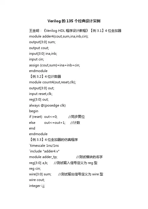
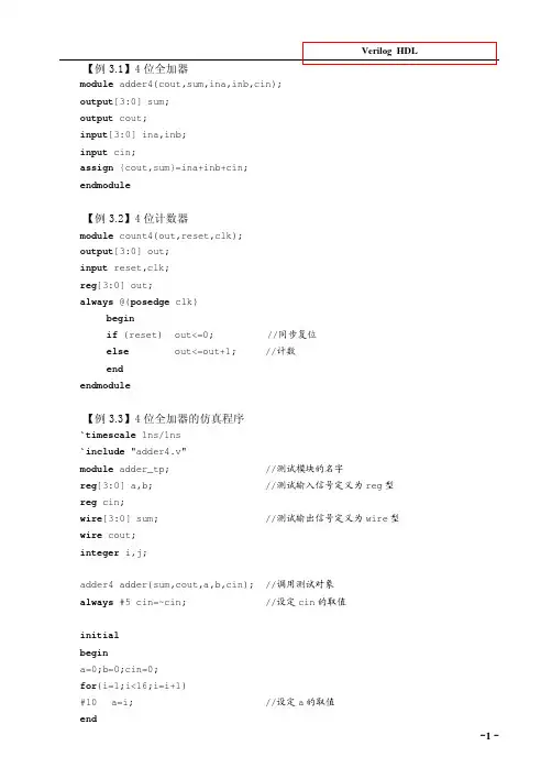
Verilog的135个经典设计实例王金明:《Verilog HDL程序设计教程》【例3.1】4位全加器module adder4(cout,sum,ina,inb,cin);output[3:0] sum;output cout;input[3:0] ina,inb;input cin;assign {cout,sum}=ina+inb+cin;endmodule【例3.2】4位计数器module count4(out,reset,clk);output[3:0] out;input reset,clk;reg[3:0] out;always @(posedge clk)beginif (reset) out<=0; //同步复位else out<=out+1; //计数endendmodule【例3.3】4位全加器的仿真程序`timescale 1ns/1ns`include "adder4.v"module adder_tp; //测试模块的名字reg[3:0] a,b; //测试输入信号定义为reg型reg cin;wire[3:0] sum; //测试输出信号定义为wire型wire cout;integer i,j;adder4 adder(sum,cout,a,b,cin); //调用测试对象always #5 cin=~cin; //设定cin的取值initialbegina=0;b=0;cin=0;for(i=1;i<16;i=i+1)#10 a=i; //设定a的取值end- 1 - 程序文本initialbeginfor(j=1;j<16;j=j+1)#10 b=j; //设定b的取值endinitial //定义结果显示格式begin$monitor($time,,,"%d + %d + %b={%b,%d}",a,b,cin,cout,sum);#160 $finish;endendmodule【例3.4】4位计数器的仿真程序`timescale 1ns/1ns`include "count4.v"module coun4_tp;reg clk,reset; //测试输入信号定义为reg型wire[3:0] out; //测试输出信号定义为wire型parameter DELY=100;count4 mycount(out,reset,clk); //调用测试对象always #(DELY/2) clk = ~clk; //产生时钟波形initialbegin //激励信号定义clk =0; reset=0;#DELY reset=1;#DELY reset=0;#(DELY*20) $finish;end//定义结果显示格式initial $monitor($time,,,"clk=%d reset=%d out=%d", clk, reset,out);endmodule【例3.5】“与-或-非”门电路module AOI(A,B,C,D,F); //模块名为AOI(端口列表A,B,C,D,F)input A,B,C,D; //模块的输入端口为A,B,C,Doutput F; //模块的输出端口为F- 2 -王金明:《Verilog HDL程序设计教程》wire A,B,C,D,F; //定义信号的数据类型assign F= ~((A&B)|(C&D)); //逻辑功能描述endmodule【例5.1】用case语句描述的4选1数据选择器module mux4_1(out,in0,in1,in2,in3,sel);output out;input in0,in1,in2,in3;input[1:0] sel;reg out;always @(in0 or in1 or in2 or in3 or sel) //敏感信号列表case(sel)2'b00: out=in0;2'b01: out=in1;2'b10: out=in2;2'b11: out=in3;default: out=2'bx;endcaseendmodule【例5.2】同步置数、同步清零的计数器module count(out,data,load,reset,clk);output[7:0] out;input[7:0] data;input load,clk,reset;reg[7:0] out;always @(posedge clk) //clk上升沿触发beginif (!reset) out = 8'h00; //同步清0,低电平有效else if (load) out = data; //同步预置else out = out + 1; //计数endendmodule【例5.3】用always过程语句描述的简单算术逻辑单元`define add 3'd0`define minus 3'd1`define band 3'd2`define bor 3'd3`define bnot 3'd4- 3 - 程序文本module alu(out,opcode,a,b);output[7:0] out;reg[7:0] out;input[2:0] opcode; //操作码input[7:0] a,b; //操作数always@(opcode or a or b) //电平敏感的always块begincase(opcode)`add: out = a+b; //加操作`minus: out = a-b; //减操作`band: out = a&b; //求与`bor: out = a|b; //求或`bnot: out=~a; //求反default: out=8'hx; //未收到指令时,输出任意态endcaseendendmodule【例5.4】用initial过程语句对测试变量A、B、C赋值`timescale 1ns/1nsmodule test;reg A,B,C;initialbeginA = 0;B = 1;C = 0;#50 A = 1; B = 0;#50 A = 0; C = 1;#50 B = 1;#50 B = 0; C = 0;#50 $finish ;endendmodule【例5.5】用begin-end串行块产生信号波形`timescale 10ns/1nsmodule wave1;reg wave;parameter cycle=10;initialbegin- 4 -王金明:《Verilog HDL程序设计教程》wave=0;#(cycle/2) wave=1;#(cycle/2) wave=0;#(cycle/2) wave=1;#(cycle/2) wave=0;#(cycle/2) wave=1;#(cycle/2) $finish ;endinitial $monitor($time,,,"wave=%b",wave); endmodule【例5.6】用fork-join并行块产生信号波形`timescale 10ns/1nsmodule wave2;reg wave;parameter cycle=5;initialforkwave=0;#(cycle) wave=1;#(2*cycle) wave=0;#(3*cycle) wave=1;#(4*cycle) wave=0;#(5*cycle) wave=1;#(6*cycle) $finish;initial $monitor($time,,,"wave=%b",wave); endmodule【例5.7】持续赋值方式定义的2选1多路选择器module MUX21_1(out,a,b,sel);input a,b,sel;output out;assign out=(sel==0)?a:b;//持续赋值,如果sel为0,则out=a ;否则out=b endmodule【例5.8】阻塞赋值方式定义的2选1多路选择器module MUX21_2(out,a,b,sel);input a,b,sel;- 5 - 程序文本output out;reg out;always@(a or b or sel)beginif(sel==0) out=a; //阻塞赋值else out=b;endendmodule【例5.9】非阻塞赋值module non_block(c,b,a,clk);output c,b;input clk,a;reg c,b;always @(posedge clk)beginb<=a;endendmodule【例5.10】阻塞赋值module block(c,b,a,clk);output c,b;input clk,a;reg c,b;always @(posedge clk)beginb=a;c=b;endendmodule【例5.11】模为60的BCD码加法计数器module count60(qout,cout,data,load,cin,reset,clk); output[7:0] qout;output cout;input[7:0] data;input load,cin,clk,reset;reg[7:0] qout;always @(posedge clk) //clk上升沿时刻计数- 6 - 王金明:《Verilog HDL程序设计教程》beginif (reset) qout<=0; //同步复位else if(load) qout<=data; //同步置数else if(cin)beginif(qout[3:0]==9) //低位是否为9,是则beginqout[3:0]<=0; //回0,并判断高位是否为5if (qout[7:4]==5) qout[7:4]<=0;elseqout[7:4]<=qout[7:4]+1; //高位不为5,则加1endelse //低位不为9,则加1qout[3:0]<=qout[3:0]+1;endendassign cout=((qout==8'h59)&cin)?1:0; //产生进位输出信号endmodule【例5.12】BCD码—七段数码管显示译码器module decode4_7(decodeout,indec);output[6:0] decodeout;input[3:0] indec;reg[6:0] decodeout;always @(indec)begincase(indec) //用case语句进行译码4'd0:decodeout=7'b1111110;4'd1:decodeout=7'b0110000;4'd2:decodeout=7'b1101101;4'd3:decodeout=7'b1111001;4'd4:decodeout=7'b0110011;4'd5:decodeout=7'b1011011;4'd6:decodeout=7'b1011111;4'd7:decodeout=7'b1110000;4'd8:decodeout=7'b1111111;4'd9:decodeout=7'b1111011;default: decodeout=7'bx;endcaseend- 7 - 程序文本endmodule【例5.13】用casez描述的数据选择器module mux_casez(out,a,b,c,d,select); output out;input a,b,c,d;input[3:0] select;reg out;always @(select or a or b or c or d) begincasez(select)4'b1: out = a;4'b??1?: out = b;4'b?1??: out = c;4'b1: out = d;endcaseendendmodule【例5.14】隐含锁存器举例module buried_ff(c,b,a);output c;input b,a;reg c;always @(a or b)beginif((b==1)&&(a==1)) c=a&b;endendmodule【例5.15】用for语句描述的七人投票表决器module voter7(pass,vote);output pass;input[6:0] vote;reg[2:0] sum;integer i;reg pass;always @(vote)beginsum=0;- 8 -王金明:《Verilog HDL程序设计教程》for(i=0;i<=6;i=i+1) //for语句if(vote[i]) sum=sum+1;if(sum[2]) pass=1; //若超过4人赞成,则pass=1 else pass=0;endendmodule【例5.16】用for语句实现2个8位数相乘module mult_for(outcome,a,b);parameter size=8;input[size:1] a,b; //两个操作数output[2*size:1] outcome; //结果reg[2*size:1] outcome;integer i;always @(a or b)beginoutcome=0;for(i=1; i<=size; i=i+1) //for语句if(b[i]) outcome=outcome +(a << (i-1));endendmodule【例5.17】用repeat实现8位二进制数的乘法module mult_repeat(outcome,a,b);parameter size=8;input[size:1] a,b;output[2*size:1] outcome;reg[2*size:1] temp_a,outcome;reg[size:1] temp_b;always @(a or b)beginoutcome=0;temp_a=a;temp_b=b;repeat(size) //repeat语句,size为循环次数beginif(temp_b[1]) //如果temp_b的最低位为1,就执行下面的加法outcome=outcome+temp_a;temp_a=temp_a<<1; //操作数a左移一位- 9 - 程序文本temp_b=temp_b>>1; //操作数b右移一位endendendmodule【例5.18】同一循环的不同实现方式module loop1; //方式1integer i;initialfor(i=0;i<4;i=i+1) //for语句begin$display(“i=%h”,i);endendmodulemodule loop2; //方式2integer i;initial begini=0;while(i<4) //while语句begin$display ("i=%h",i);i=i+1;endendendmodulemodule loop3; //方式3integer i;initial begini=0;repeat(4) //repeat语句begin$display ("i=%h",i);i=i+1;endendendmodule【例5.19】使用了`include语句的16位加法器- 10 -王金明:《Verilog HDL程序设计教程》`include "adder.v" module adder16(cout,sum,a,b,cin);output cout;parameter my_size=16;output[my_size-1:0] sum;input[my_size-1:0] a,b;input cin;adder my_adder(cout,sum,a,b,cin); //调用adder模块endmodule//下面是adder模块代码module adder(cout,sum,a,b,cin);parameter size=16;output cout;output[size-1:0] sum;input cin;input[size-1:0] a,b;assign {cout,sum}=a+b+cin;endmodule【例5.20】条件编译举例module compile(out,A,B);output out;input A,B;`ifdef add //宏名为addassign out=A+B;`elseassign out=A-B;`endifendmodule【例6.1】加法计数器中的进程module count(data,clk,reset,load,cout,qout);output cout;output[3:0] qout;reg[3:0] qout;input[3:0] data;input clk,reset,load;- 11 - 程序文本always @(posedge clk) //进程1,always过程块beginif (!reset) qout= 4'h00; //同步清0,低电平有效else if (load) qout= data; //同步预置else qout=qout + 1; //加法计数endassign cout=(qout==4'hf)?1:0; //进程2,用持续赋值产生进位信号endmodule【例6.2】任务举例module alutask(code,a,b,c);input[1:0] code;input[3:0] a,b;output[4:0] c;reg[4:0] c;task my_and; //任务定义,注意无端口列表input[3:0] a,b; //a,b,out名称的作用域范围为task任务内部output[4:0] out;integer i;beginfor(i=3;i>=0;i=i-1)out[i]=a[i]&b[i]; //按位与endendtaskalways@(code or a or b)begincase(code)2'b00: my_and(a,b,c);/* 用任务my_and,需注意端口列表的顺序应与任务定义中的一致,这里的a,b,c分别对应任务定义中的a,b,out */2'b01: c=a|b; //或2'b10: c=a-b; //相减2'b11: c=a+b; //相加endcaseendendmodule- 12 -王金明:《Verilog HDL程序设计教程》【例6.3】测试程序`include "alutask.v"module alu_tp;reg[3:0] a,b;reg[1:0] code;wire[4:0] c;parameter DELY = 100;alutask ADD(code,a,b,c); //调用被测试模块initial begincode=4'd0; a= 4'b0000; b= 4'b1111;#DELY code=4'd0; a= 4'b0111; b= 4'b1101;#DELY code=4'd1; a= 4'b0001; b= 4'b0011;#DELY code=4'd2; a= 4'b1001; b= 4'b0011;#DELY code=4'd3; a= 4'b0011; b= 4'b0001;#DELY code=4'd3; a= 4'b0111; b= 4'b1001;#DELY $finish;endinitial $monitor($time,,,"code=%b a=%b b=%b c=%b", code,a,b,c);endmodule【例6.4】函数function[7:0] get0;input[7:0] x;reg[7:0] count;integer i;begincount=0;for (i=0;i<=7;i=i+1)if (x[i]=1'b0) count=count+1;get0=count;endendfunction【例6.5】用函数和case语句描述的编码器(不含优先顺序)module code_83(din,dout);input[7:0] din;output[2:0] dout;- 13 - 程序文本function[2:0] code; //函数定义input[7:0] din; //函数只有输入,输出为函数名本身casex (din)8'b1xxx_xxxx : code = 3'h7;8'b01xx_xxxx : code = 3'h6;8'b001x_xxxx : code = 3'h5;8'b0001_xxxx : code = 3'h4;8'b0000_1xxx : code = 3'h3;8'b0000_01xx : code = 3'h2;8'b0000_001x : code = 3'h1;8'b0000_000x : code = 3'h0;default: code = 3'hx;endcaseendfunctionassign dout = code(din) ; //函数调用endmodule【例6.6】阶乘运算函数module funct(clk,n,result,reset);output[31:0] result;input[3:0] n;input reset,clk;reg[31:0] result;always @(posedge clk) //在clk的上升沿时执行运算beginif(!reset) result<=0; //复位else beginresult <= 2 * factorial(n); //调用factorial函数endendfunction[31:0] factorial; //阶乘运算函数定义(注意无端口列表)input[3:0] opa; //函数只能定义输入端,输出端口为函数名本身reg[3:0] i;beginfactorial = opa ? 1 : 0;for(i= 2; i <= opa; i = i+1) //该句若要综合通过,opa应赋具体的数值factorial = i* factorial; //阶乘运算end- 14 -王金明:《Verilog HDL程序设计教程》endfunction【例6.7】测试程序`define clk_cycle 50`include "funct.v"module funct_tp;reg[3:0] n;reg reset,clk;wire[31:0] result;initial //定义激励向量beginn=0; reset=1; clk=0;for(n=0;n<=15;n=n+1)#100 n=n;endinitial $monitor($time,,,"n=%d result=%d",n,result);//定义输出显示格式always # `clk_cycle clk=~clk; //产生时钟信号funct funct_try(.clk(clk),.n(n),.result(result),.reset(reset)); //调用被测试模块endmodule【例6.8】顺序执行模块1module serial1(q,a,clk);output q,a;input clk;reg q,a;always @(posedge clk)beginq=~q;a=~q;end【例6.9】顺序执行模块2 module serial2(q,a,clk); output q,a;- 15 - 程序文本input clk;reg q,a;always @(posedge clk) begina=~q;q=~q;endendmodule【例6.10】并行执行模块1 module paral1(q,a,clk); output q,a;input clk;reg q,a;always @(posedge clk) beginq=~q;endalways @(posedge clk) begina=~q;endendmodule【例6.11】并行执行模块2 module paral2(q,a,clk); output q,a;input clk;reg q,a;always @(posedge clk)begina=~q;endalways @(posedge clk)beginq=~q;endendmodule【例7.1】调用门元件实现的4选1 MUX- 16 -王金明:《Verilog HDL程序设计教程》module mux4_1a(out,in1,in2,in3,in4,cntrl1,cntrl2);output out;input in1,in2,in3,in4,cntrl1,cntrl2;wire notcntrl1,notcntrl2,w,x,y,z;not notcntrl1,cntrl2),(notcntrl2,cntrl2);and (w,in1,notcntrl1,notcntrl2),(x,in2,notcntrl1,cntrl2),(y,in3,cntrl1,notcntrl2),(z,in4,cntrl1,cntrl2);or (out,w,x,y,z);endmodule【例7.2】用case语句描述的4选1 MUXmodule mux4_1b(out,in1,in2,in3,in4,cntrl1,cntrl2);output out;input in1,in2,in3,in4,cntrl1,cntrl2;reg out;always@(in1 or in2 or in3 or in4 or cntrl1 or cntrl2)case({cntrl1,cntrl2})2'b00:out=in1;2'b01:out=in2;2'b10:out=in3;2'b11:out=in4;default:out=2'bx;endcaseendmodule【例7.3】行为描述方式实现的4位计数器module count4(clk,clr,out);input clk,clr;output[3:0] out;reg[3:0] out;always @(posedge clk or posedge clr)beginif (clr) out<=0;else out<=out+1;endendmodule- 17 - 程序文本【例7.4】数据流方式描述的4选1 MUXmodule mux4_1c(out,in1,in2,in3,in4,cntrl1,cntrl2);output out;input in1,in2,in3,in4,cntrl1,cntrl2;assign out=(in1 & ~cntrl1 & ~cntrl2)|(in2 & ~cntrl1 & cntrl2)|(in3 & cntrl1 & ~cntrl2)|(in4 & cntrl1 & cntrl2);endmodule【例7.5】用条件运算符描述的4选1 MUXmodule mux4_1d(out,in1,in2,in3,in4,cntrl1,cntrl2); output out;input in1,in2,in3,in4,cntrl1,cntrl2;assign out=cntrl1 ? (cntrl2 ? in4:in3):(cntrl2 ? in2:in1); endmodule【例7.6】门级结构描述的2选1MUXmodule mux2_1a(out,a,b,sel);output out;input a,b,sel;not (sel_,sel);and a1,a,sel_),(a2,b,sel);or (out,a1,a2);endmodule【例7.7】行为描述的2选1MUXmodule mux2_1b(out,a,b,sel);output out;input a,b,sel;reg out;always @(a or b or sel)beginif(sel) out = b;else out = a;endendmodule【例7.8】数据流描述的2选1MUXmodule MUX2_1c(out,a,b,sel);output out;- 18 -王金明:《Verilog HDL程序设计教程》input a,b,sel;assign out = sel ? b : a; endmodule【例7.9】调用门元件实现的1位半加器module half_add1(a,b,sum,cout); input a,b;output sum,cout;and cout,a,b);xor sum,a,b);endmodule【例7.10】数据流方式描述的1位半加器module half_add2(a,b,sum,cout); input a,b;output sum,cout;assign sum=a^b;assign cout=a&b;endmodule【例7.11】采用行为描述的1位半加器module half_add3(a,b,sum,cout); input a,b;output sum,cout;reg sum,cout;always @(a or b)begincase ({a,b}) //真值表描述2'b00: begin sum=0; cout=0; end2'b01: begin sum=1; cout=0; end2'b10: begin sum=1; cout=0; end2'b11: begin sum=0; cout=1; end endcaseendendmodule【例7.12】采用行为描述的1位半加器module half_add4(a,b,sum,cout); input a,b;output sum,cout;- 19 - 程序文本reg sum,cout;always @(a or b)beginsum= a^b;cout=a&b;endendmodule【例7.13】调用门元件实现的1位全加器module full_add1(a,b,cin,sum,cout); input a,b,cin;output sum,cout;wire s1,m1,m2,m3;and m1,a,b),(m2,b,cin),(m3,a,cin);xor s1,a,b),(sum,s1,cin);or (cout,m1,m2,m3);endmodule【例7.14】数据流描述的1位全加器module full_add2(a,b,cin,sum,cout); input a,b,cin;output sum,cout;assign sum = a ^ b ^ cin;assign cout = (a & b)|(b & cin)|(cin & a);endmodule【例7.15】1位全加器module full_add3(a,b,cin,sum,cout);input a,b,cin;output sum,cout;assign {cout,sum}=a+b+cin;endmodule【例7.16】行为描述的1位全加器module full_add4(a,b,cin,sum,cout);input a,b,cin;output sum,cout;- 20 -王金明:《Verilog HDL程序设计教程》reg sum,cout; //在always块中被赋值的变量应定义为reg型reg m1,m2,m3;always @(a or b or cin)beginsum = (a ^ b) ^ cin;m1 = a & b;m2 = b & cin;m3 = a & cin;cout = (m1|m2)|m3;endendmodule【例7.17】混合描述的1位全加器module full_add5(a,b,cin,sum,cout);input a,b,cin;output sum,cout;reg cout,m1,m2,m3; //在always块中被赋值的变量应定义为reg型wire s1;xor x1(s1,a,b); //调用门元件always @(a or b or cin) //always块语句beginm1 = a & b;m2 = b & cin;m3 = a & cin;cout = (m1| m2) | m3;endassign sum = s1 ^ cin; //assign持续赋值语句endmodule【例7.18】结构描述的4位级连全加器`include "full_add1.v"module add4_1(sum,cout,a,b,cin);output[3:0] sum;output cout;input[3:0] a,b;input cin;full_add1 f0(a[0],b[0],cin,sum[0],cin1); //级连描述full_add1 f1(a[1],b[1],cin1,sum[1],cin2);full_add1 f2(a[2],b[2],cin2,sum[2],cin3);- 21 - 程序文本full_add1 f3(a[3],b[3],cin3,sum[3],cout); endmodule【例7.19】数据流描述的4位全加器module add4_2(cout,sum,a,b,cin);output[3:0] sum;output cout;input[3:0] a,b;input cin;assign {cout,sum}=a+b+cin;endmodule【例7.20】行为描述的4位全加器module add4_3(cout,sum,a,b,cin);output[3:0] sum;output cout;input[3:0] a,b;input cin;reg[3:0] sum;reg cout;always @(a or b or cin)begin{cout,sum}=a+b+cin;endendmodule【例8.1】$time与$realtime的区别`timescale 10ns/1nsmodule time_dif;reg ts;parameter delay=2.6;initialbegin#delay ts=1;#delay ts=0;#delay ts=1;#delay ts=0;endinitial $monitor($time,,,"ts=%b",ts); //使用函数$time- 22 - 王金明:《Verilog HDL程序设计教程》endmodule【例8.2】$random函数的使用`timescale 10ns/1nsmodule random_tp;integer data;integer i;parameter delay=10;initial $monitor($time,,,"data=%b",data);initial beginfor(i=0; i<=100; i=i+1)#delay data=$random; //每次产生一个随机数endendmodule【例8.3】1位全加器进位输出UDP元件primitive carry_udp(cout,cin,a,b);input cin,a,b;output cout;table//cin a b : cout //真值表0 0 0 : 0;0 1 0 : 0;0 0 1 : 0;0 1 1 : 1;1 0 0 : 0;1 0 1 : 1;1 1 0 : 1;1 1 1 : 1;endtableendprimitive【例8.4】包含x态输入的1位全加器进位输出UDP元件primitive carry_udpx1(cout,cin,a,b);input cin,a,b;output cout;table// cin a b : cout //真值表0 0 0 : 0;- 23 - 程序文本0 1 0 : 0;0 0 1 : 0;0 1 1 : 1;1 0 0 : 0;1 0 1 : 1;1 1 0 : 1;1 1 1 : 1;0 0 x : 0; //只要有两个输入为0,则进位输出肯定为0 0 x 0 : 0;x 0 0 : 0;1 1 x : 1; //只要有两个输入为1,则进位输出肯定为1 1 x 1 : 1;x 1 1 : 1;endtableendprimitive【例8.5】用简缩符“?”表述的1位全加器进位输出UDP元件primitive carry_udpx2(cout,cin,a,b);input cin,a,b;output cout;table// cin a b : cout //真值表0 0 : 0; //只要有两个输入为0,则进位输出肯定为00 ? 0 : 0;0 0 ? : 0;1 1 : 1; //只要有两个输入为1,则进位输出肯定为11 ? 1 : 1;1 1 ? : 1;endtableendprimitive【例8.6】3选1多路选择器UDP元件primitive mux31(Y,in0,in1,in2,s2,s1);input in0,in1,in2,s2,s1;output Y;table//in0 in1 in2 s2 s1 : Y0 ? ? 0 0 : 0; //当s2s1=00时,Y=in01 ? ? 0 0 : 1;0 ? 0 1 : 0; //当s2s1=01时,Y=in1 - 24 -王金明:《Verilog HDL程序设计教程》1 ? 0 1 : 1;0 1 ? : 0; //当s2s1=1?时,Y=in21 1 ? : 1;0 0 ? 0 ? : 0;1 1 ? 0 ? : 1;0 ? 0 ? 0 : 0;1 ? 1 ? 0 : 1;0 0 ? 1 : 0;1 1 ? 1 : 1;endtableendprimitive【例8.7】电平敏感的1位数据锁存器UDP元件primitive latch(Q,clk,reset,D);input clk,reset,D;output Q;reg Q;initial Q = 1'b1; //初始化table// clk reset D : state : Q1 ? : ? : 0 ; //reset=1,则不管其他端口为什么值,输出都为00 0 0 : ? : 0 ; //clk=0,锁存器把D端的输入值输出0 0 1 : ? : 1 ;1 0 ? : ? : - ; //clk=1,锁存器的输出保持原值,用符号“-”表示endtableendprimitive【例8.8】上升沿触发的D触发器UDP元件primitive DFF(Q,D,clk);output Q;input D,clk;reg Q;table//clk D : state : Q(01) 0 : ? : 0; //上升沿到来,输出Q=D(01) 1 : ? : 1;(0x) 1 : 1 : 1;(0x) 0 : 0 : 0;(?0) ? : ? : -; //没有上升沿到来,输出Q保持原值(??) : ? : - ; //时钟不变,输出也不变- 25 - 程序文本endtableendprimitive【例8.9】带异步置1和异步清零的上升沿触发的D触发器UDP 元件primitive DFF_UDP(Q,D,clk,clr,set);output Q;input D,clk,clr,set;reg Q;table// clk D clr et state : Q (01) 1 0 0 : ? : 0; (01) 1 0 x : ? : 0;0 x : 0 : 0;(01) 0 0 0 : ? : 1; (01) 0 x 0 : ? : 1;x 0 : 1 : 1;(x1) 1 0 0 : 0 : 0;(x1) 0 0 0 : 1 : 1;(0x) 1 0 0 : 0 : 0;(0x) 0 0 0 : 1 : 1;1 ? : ? : 1; //异步复位0 1 : ? : 0; //异步置1 n ? 0 0 : ? : -;* ? ? : ? : -;(?0) ? : ? : -;(?0): ? : -;: ? : x;endtableendprimitive【例8.12】延迟定义块举例module delay(out,a,b,c); output out;input a,b,c;and a1(n1,a,b);or o1(out,c,n1);specify(a=>out)=2;(b=>out)=3;(c=>out)=1;- 26 -王金明:《Verilog HDL程序设计教程》endspecifyendmodule【例8.13】激励波形的描述'timescale 1ns/1nsmodule test1;reg A,B,C;initialbegin //激励波形描述A = 0;B = 1;C = 0;#100 C = 1;#100 A = 1; B = 0;#100 A = 0;#100 C = 0;#100 $finish;endinitial $monitor($time,,,"A=%d B=%d C=%d",A,B,C); //显示endmodule【例8.15】用always过程块产生两个时钟信号module test2;reg clk1,clk2;parameter CYCLE = 100;alwaysbegin{clk1,clk2} = 2'b10;#(CYCLE/4) {clk1,clk2} = 2'b01;#(CYCLE/4) {clk1,clk2} = 2'b11;#(CYCLE/4) {clk1,clk2} = 2'b00;#(CYCLE/4) {clk1,clk2} = 2'b10;endinitial $monitor($time,,,"clk1=%b clk2=%b",clk1,clk2); endmodule【例8.17】存储器在仿真程序中的应用module ROM(addr,data,oe);output[7:0] data; //数据信号input[14:0] addr; //地址信号input oe; //读使能信号,低电平有效- 27 - 程序文本reg[7:0] mem[0:255]; //存储器定义parameter DELAY = 100;assign #DELAY data=(oe==0) ? mem[addr] : 8'hzz; initial $readmemh("rom.hex",mem); //从文件中读入数据endmodule【例8.18】8位乘法器的仿真程序`timescale 10ns/1nsmodule mult_tp; //测试模块的名字reg[7:0] a,b; //测试输入信号定义为reg型wire [15:0] out; //测试输出信号定义为wire型integer i,j;mult8 m1(out,a,b); //调用测试对象//激励波形设定initialbegina=0;b=0;for(i=1;i<255;i=i+1)#10 a=i;endinitialbeginfor(j=1;j<255;j=j+1)#10 b=j;endinitial //定义结果显示格式begin$monitor($time,,,"%d * %d= %d",a,b,out);#2560 $finish;endendmodulemodule mult8(out, a, b); //8位乘法器源代码parameter size=8;input[size:1] a,b; //两个操作数output[2*size:1] out; //结果assign out=a*b; //乘法运算符- 28 -王金明:《Verilog HDL程序设计教程》endmodule 【例8.19】8位加法器的仿真程序`timescale 1ns/1nsmodule add8_tp; //仿真模块无端口列表reg[7:0] A,B; //输入激励信号定义为reg型reg cin;wire[7:0] SUM; //输出信号定义为wire型wire cout;parameter DELY = 100;add8 AD1(SUM,cout,A,B,cin); //调用测试对象initial begin //激励波形设定A= 8'd0; B= 8'd0; cin=1'b0;#DELY A= 8'd100; B= 8'd200; cin=1'b1;#DELY A= 8'd200; B= 8'd88;#DELY A= 8'd210; B= 8'd18; cin=1'b0;#DELY A= 8'd12; B= 8'd12;#DELY A= 8'd100; B= 8'd154;#DELY A= 8'd255; B= 8'd255; cin=1'b1;#DELY $finish;end//输出格式定义initial $monitor($time,,,"%d + %d + %b = {%b, %d}",A,B,cin,cout,SUM);endmodulemodule add8(SUM,cout,A,B,cin); //待测试的8位加法器模块output[7:0] SUM;output cout;input[7:0] A,B;input cin;assign {cout,SUM}=A+B+cin;endmodule【例8.20】2选1多路选择器的仿真`timescale 1ns/1nsmodule mux_tp;reg a,b,sel;wire out;- 29 - 程序文本MUX2_1 m1(out,a,b,sel); //调用待测试模块initialbegina=1'b0; b=1'b0; sel=1'b0;#5 sel=1'b1;#5 a=1'b1; el=1'b0;#5 sel=1'b1;#5 a=1'b0; b=1'b1; el=1'b0;#5 sel=1'b1;#5 a=1'b1; b=1'b1; sel=1'b0;#5 sel=1'b1;endinitial $monitor($time,,,"a=%b b=%b sel=%b out=%b",a,b,sel,out);endmodulemodule MUX2_1(out,a,b,sel); //待测试的2选1MUX模块input a,b,sel;output out;not #(0.4,0.3) (sel_,sel); //#(0.4,0.3)为门延时and #(0.7,0.6) (a1,a,sel_);and #(0.7,0.6) (a2,b,sel);or #(0.7,0.6) (out,a1,a2);endmodule【例8.21】8位计数器的仿真`timescale 10ns/1nsmodule count8_tp;reg clk,reset; //输入激励信号定义为reg型wire[7:0] qout; //输出信号定义为wire型parameter DELY=100;counter C1(qout,reset,clk); //调用测试对象always #(DELY/2) clk = ~clk; //产生时钟波形initialbegin //激励波形定义clk =0; reset=0;- 30 -王金明:《Verilog HDL程序设计教程》#DELY reset=1;#DELY reset=0;#(DELY*300) $finish;end//结果显示initial $monitor($time,,,"clk=%d reset=%d qout=%d",clk,reset,qout);endmodulemodule counter(qout,reset,clk); //待测试的8位计数器模块output[7:0] qout;input clk,reset;reg[7:0] qout;always @(posedge clk)begin if (reset) qout<=0;else qout<=qout+1;endendmodule【例9.1】基本门电路的几种描述方法(1)门级结构描述module gate1(F,A,B,C,D);input A,B,C,D;output F;nand(F1,A,B); //调用门元件and(F2,B,C,D);or(F,F1,F2);endmodule(2)数据流描述module gate2(F,A,B,C,D);input A,B,C,D;output F;assign F=(A&B)|(B&C&D); //assign持续赋值endmodule(3)行为描述module gate3(F,A,B,C,D);input A,B,C,D;output F;- 31 - 程序文本reg F;always @(A or B or C or D) //过程赋值beginF=(A&B)|(B&C&D);endendmodule【例9.2】用bufif1关键字描述的三态门module tri_1(in,en,out);input in,en;output out;tri out;bufif1 b1(out,in,en); //注意三态门端口的排列顺序endmodule【例9.3】用assign语句描述的三态门module tri_2(out,in,en);output out;input in,en;assign out = en ? in : 'bz;//若en=1,则out=in;若en=0,则out为高阻态endmodule【例9.4】三态双向驱动器module bidir(tri_inout,out,in,en,b);inout tri_inout;output out;input in,en,b;assign tri_inout = en ? in : 'bz;assign out = tri_inout ^ b; endmodule【例9.5】三态双向驱动器module bidir2(bidir,en,clk);inout[7:0] bidir;input en,clk;reg[7:0] temp;assign bidir= en ? temp : 8'bz; always @(posedge clk)begin- 32 -王金明:《Verilog HDL程序设计教程》if(en) temp=bidir;else temp=temp+1;endendmodule【例9.6】3-8译码器module decoder_38(out,in);output[7:0] out;input[2:0] in;reg[7:0] out;always @(in)begincase(in)3'd0: out=8'b11111110;3'd1: out=8'b11111101;3'd2: out=8'b11111011;3'd3: out=8'b11110111;3'd4: out=8'b11101111;3'd5: out=8'b11011111;3'd6: out=8'b10111111;3'd7: out=8'b01111111;endcaseendendmodule【例9.7】8-3优先编码器module encoder8_3(none_on,outcode,a,b,c,d,e,f,g,h); output none_on;output[2:0] outcode;input a,b,c,d,e,f,g,h;reg[3:0] outtemp;assign {none_on,outcode}=outtemp;always @(a or b or c or d or e or f or g or h)beginif(h) outtemp=4'b0111;else if(g) outtemp=4'b0110;else if(f) outtemp=4'b0101;else if(e) outtemp=4'b0100;else if(d) outtemp=4'b0011;else if(c) outtemp=4'b0010;- 33 - 程序文本else if(b) outtemp=4'b0001;else if(a) outtemp=4'b0000;else outtemp=4'b1000;endendmodule【例9.8】用函数定义的8-3优先编码器module code_83(din, dout);input[7:0] din;output[2:0] dout;function[2:0] code; //函数定义input[7:0] din; //函数只有输入端口,输出为函数名本身if (din[7]) code = 3'd7;else if (din[6]) code = 3'd6;else if (din[5]) code = 3'd5;else if (din[4]) code = 3'd4;else if (din[3]) code = 3'd3;else if (din[2]) code = 3'd2;else if (din[1]) code = 3'd1;else code = 3'd0;endfunctionassign dout = code(din); //函数调用endmodule【例9.9】七段数码管译码器module decode47(a,b,c,d,e,f,g,D3,D2,D1,D0);output a,b,c,d,e,f,g;input D3,D2,D1,D0; //输入的4位BCD码reg a,b,c,d,e,f,g;always @(D3 or D2 or D1 or D0)begincase({D3,D2,D1,D0}) //用case语句进行译码4'd0: {a,b,c,d,e,f,g}=7'b1111110;4'd1: {a,b,c,d,e,f,g}=7'b0110000;4'd2: {a,b,c,d,e,f,g}=7'b1101101;4'd3: {a,b,c,d,e,f,g}=7'b1111001;4'd4: {a,b,c,d,e,f,g}=7'b0110011;4'd5: {a,b,c,d,e,f,g}=7'b1011011;- 34 -王金明:《Verilog HDL程序设计教程》4'd6: {a,b,c,d,e,f,g}=7'b1011111;。

K X康芯科技实验5-1. 7段数码显示译码器设计例5-18LIBRARY IEEE ;USE IEEE.STD_LOGIC_1164.ALL ;ENTITY DECL7S ISPORT ( A : IN STD_LOGIC_VECTOR(3 DOWNTO 0);LED7S : OUT STD_LOGIC_VECTOR(6 DOWNTO 0) ) ;END ;ARCHITECTURE one OF DECL7S ISBEGINPROCESS( A )BEGINCASE A ISWHEN "0000" => LED7S <= "0111111" ;WHEN "0001" => LED7S <= "0000110" ;WHEN "0010" => LED7S <= "1011011" ;WHEN "0011" => LED7S <= "1001111" ;WHEN "0100" => LED7S <= "1100110" ;WHEN "0101" => LED7S <= "1101101" ;WHEN "0110" => LED7S <= "1111101" ;WHEN "0111" => LED7S <= "0000111" ;WHEN "1000" => LED7S <= "1111111" ;WHEN "1001" => LED7S <= "1101111" ;WHEN "1010" => LED7S <= "1110111" ;WHEN "1011" => LED7S <= "1111100" ;WHEN "1100" => LED7S <= "0111001" ;WHEN "1101" => LED7S <= "1011110" ;WHEN "1110" => LED7S <= "1111001" ;WHEN "1111" => LED7S <= "1110001" ;WHEN OTHERS => NULL ;END CASE ;END PROCESS ;END ;K X康芯科技模式5的电路结构在模式5中,键1接PIO0,对应EP1C3的第1脚。
verilog 组合逻辑例子Verilog组合逻辑例子Verilog是一种硬件描述语言,常用于数字逻辑综合和编写硬件模块。
组合逻辑是Verilog中的一种基本类型,用于描述没有存储功能,只有输入和输出之间逻辑关系的电路。
以下是一些Verilog组合逻辑例子及其详细讲解。
1. 逻辑门AND门module and_gate(input a,input b,output y);assign y = a && b;endmodule在这个例子中,我们定义了一个AND门的模块。
它有两个输入a 和b,一个输出y。
通过assign语句,我们将输出y赋值为输入a和b 的逻辑与结果。
OR门module or_gate(input a,input b,output y);assign y = a || b;endmodule这是一个OR门的例子。
和AND门类似,我们通过assign语句将输出y赋值为输入a和b的逻辑或结果。
2. 多路选择器module mux(input a,input b,input c,input d,input [1:0] sel,output y);assign y = (sel == 2'b00) ? a :(sel == 2'b01) ? b :(sel == 2'b10) ? c :d;endmodule这个例子演示了一个4路多路选择器。
它有4个输入a、b、c和d,一个2位选择信号sel,一个输出y。
根据选择信号的不同值,输出y将根据如下规则选择不同的输入信号:00选择a,01选择b,10选择c,11选择d。
3. 比较器module comparator(input [3:0] a,input [3:0] b,output eq,output gt,output lt);assign eq = (a == b);assign gt = (a > b);assign lt = (a < b);endmodule上面的例子展示了一个比较器。
Verilog多模块编程实例1. 介绍Verilog是一种硬件描述语言,被广泛应用于数字电路设计。
Verilog具有模块化设计的特点,可以将一个大型的电路设计分解成多个小模块,然后逐个实现和调试。
本文将介绍Verilog多模块编程的实例,以帮助读者了解如何使用Verilog进行模块化设计。
2. 模块化设计的优势模块化设计是一种将大型系统分解成多个小模块的设计方法。
在Verilog中,模块化设计有以下几个优势:- 提高代码可读性:通过将大型系统分解成多个小模块,可以提高代码的可读性和可维护性。
- 便于调试:每个小模块相对独立,可以单独调试和测试,提高了系统的可靠性和稳定性。
- 提高复用性:将功能相似的代码封装成模块,可以提高代码的复用性,减少代码冗余。
3. 多模块编程实例接下来,我们将通过一个简单的数字电路设计来演示Verilog多模块编程的实例。
假设我们要设计一个4位全加器电路,首先我们需要实现一个单位全加器模块,然后将四个单元全加器模块连接成一个4位全加器模块。
3.1 单位全加器模块我们定义一个单位全加器模块,代码如下:```verilogmodule Adder_unit (input a, b, cin,output sum, cout);assign {cout, sum} = a + b + cin;endmodule```在单位全加器模块中,我们定义了三个输入信号a、b、cin和两个输出信号sum、cout。
其中,sum表示相加的结果,cout表示进位。
在模块内部,我们通过assign语句实现了全加器的功能。
3.2 4位全加器模块接下来,我们将四个单位全加器模块连接成一个4位全加器模块,代码如下:```verilogmodule Adder_4bit (input [3:0] a, b,input cin,output [3:0] sum,output cout);Adder_unit U0(.a(a[0]), .b(b[0]), .cin(cin), .sum(sum[0]), .cout(cout0));Adder_unit U1(.a(a[1]), .b(b[1]), .cin(cout0), .sum(sum[1]), .cout(cout1)); Adder_unit U2(.a(a[2]), .b(b[2]), .cin(cout1), .sum(sum[2]), .cout(cout2)); Adder_unit U3(.a(a[3]), .b(b[3]), .cin(cout2), .sum(sum[3]), .cout(cout));endmodule```在4位全加器模块中,我们首先定义了四个输入信号a、b和一个输入信号cin,以及四个输出信号sum和一个输出信号cout。
verilog状态机设计例题Verilog状态机设计是数字电路设计中的重要内容,它通常用于控制系统和序列逻辑电路的设计。
在Verilog中,状态机通常使用行为级描述或者结构级描述来实现。
下面我将从例题的角度来介绍Verilog状态机设计。
假设我们要设计一个简单的2位计数器,它可以按顺序循环输出00、01、10、11、00……的计数序列。
我们可以使用Verilog来实现这个状态机。
首先,我们需要定义状态机的状态和状态转移。
在这个例子中,我们有4个状态:S0、S1、S2和S3,分别对应00、01、10、11四种计数状态。
状态转移规则如下:当当前状态为S0时,下一个状态为S1;当当前状态为S1时,下一个状态为S2;当当前状态为S2时,下一个状态为S3;当当前状态为S3时,下一个状态为S0。
接下来,我们可以使用Verilog的行为级描述来实现这个状态机。
下面是一个简单的Verilog代码示例:verilog.module counter (。
input clk, // 时钟输入。
input rst, // 复位输入。
output reg [1:0] count // 2位计数输出。
);// 定义状态。
typedef enum {S0, S1, S2, S3} state_type;reg [1:0] state, next_state;// 状态转移逻辑。
always @(posedge clk or posedge rst) begin.if (rst) begin.state <= S0; // 复位时初始状态为S0。
end.else begin.state <= next_state; // 根据下一个状态更新当前状态。
end.end.// 下一个状态逻辑。
case (state)。
S0: next_state = S1;S1: next_state = S2;S2: next_state = S3;S3: next_state = S0;default: next_state = S0;endcase.end.// 输出逻辑。
基于VerilogHDL的出租车计费器的实现摘要本文介绍了出租车计费器系统的组成及工作原理,采用自顶而下的设计方法,设计了一种基于硬件描述语言的出租车自动计费器,在cpld芯片epm3256atc144-7上实现了其功能,并论述了显示模块、主控模块、计费模块等实现方法。
关键词 cpld;硬件描述语言;出租车计费器中图分类号u463 文献标识码a 文章编号1674-6708(2010)21-0137-02随着cpld/fpga等数字可编程器件的出现,他们可以解决传统电子设计不能完成的任务。
利用cpld来实现出租车计费器,可行性很高,而且电路简单,大大减少外围器件,可以用软件完全仿真,灵活度高,可以设计一些复杂的系统,而且编好的系统可以在不同的fpga或cpld芯片上通用。
1 mars-eda-s实验主板本设计采用了 mars-eda-s实验主板,其核心芯片是altera公司的 epm3256atc144-7芯片。
板上具有如下资源:主芯片:epm3256atc144-7,有源晶振:40mhz;复位芯片:stc811,支持复位手动输入,支持jtag下载模式。
核心板可以作为原型板,用户可以根据自己需要自行扩展。
2 出租车计费器系统设计概述基于cpld设计的出租车自动计费器,计费包括起步价、行车里程计费、等待时间计费3部分,用三位数码管显示总金额,最大值为99.9元。
起步价为5.0元,3km之内按起步价计费,超过3km的,每1km增加1元,等待时间单价为每分钟0.1元。
用两位数码管显示总里程,最大值为99km,用两位数码管等待时间,最大值为99min。
系统框图如图1所示。
2.1 分频模块由于epm3256atc144-7芯片的时钟频率为40mhz,而主控模块所用频率为1hz,必须经过分频才能使得epm3256atc144-7芯片与程序匹配。
//分频/*信号定义:clk_in:输入时钟信号:大小为40mhz;clk:输出时钟信号;大小为1hz;*/module clock_send(clk_in,clk);input clk_in;output clk;reg clock;reg clk;reg[24:0] cnt;always@(posedge clk_in)begincnt<=cnt+1;if(cnt==25’d1*******)begincnt<=0;clock=~clock;endclk<=clock;endendmodule2.2 主控模块在主控模块中,设置拨码开关m控制led灯使系统显示出租车的当前状态,当led灯亮时开始计程,计费显示起步价5元,3km之内为起步价,即300个clk之内为起步价,以后每1km增加1元,即每10个clk增加0.1元;led灯灭时开始记等待时间,每分钟计费增加0.1元,即每60个clk增加0.1元。
verilog常⽤系统函数及例⼦1.打开⽂件 integer file_id; file_id = fopen("file_path/file_name");2.写⼊⽂件:$fmonitor,$fwrite,$fdisplay,$fstrobe //$fmonitor只要有变化就⼀直记录 $fmonitor(file_id, "%format_char", parameter); $fmonitor(file_id, "%m: %t in1=%d o1=%h", $time, in1, o1);//$fwrite需要触发条件才记录 $fwrite(file_id, "%format_char", parameter);//$fdisplay需要触发条件才记录 $fdisplay(file_id, "%format_char", parameter);$fstrobe();3.读取⽂件:$fread integer file_id; file_id = $fread("file_path/file_name", "r");4.关闭⽂件:$fclose $fclose(fjile_id);5.由⽂件设定存储器初值:$readmemh,$readmemb $readmemh("file_name", memory_name"); //初始化数据为⼗六进制 $readmemb("file_name", memory_name"); //初始化数据为⼆进制6、⽂件显⽰:$monitor,$write,$display $display,$write⽤于输出信息 $display("rvel = %h hex %d decimal",rvel,rvel); $monitor($time, ,"rxd = %b txd = %b",rxd ,txd)6、⽂件定位 $fseek,⽂件定位,可以从任意点对⽂件进⾏操作; $fscanf,对⽂件⼀⾏进⾏读写。
数字系统设计与VerilogHDL课后习题习题11.1现代EDA技术的特点有哪些?1.2什么是T op-down设计方式?1.3数字系统的实现方式有哪些?各有什么优缺点?1.4什么是IP复用技术? IP核对EDA技术的应用和发展有什么意义?1.5用硬件描述语言设计数字电路的优势是什么?1.6结合自己的使用情况谈谈对EDA工具的认识。
1.7基于FPGA/CPLD的数字系统设计流程包括哪些步骤?1.8什么是综合?常用的综合工具有哪些?1.9功能仿真与时序仿真有什么区别?1.10 FPGA与ASIC在概念上有什么区别?习题22.1 PLA和PAL在结构上有什么区别?2.2说明GAL的OLMC有什么特点,它怎样实现可编程组合电路和时序电路?2.3简述基于乘积项的可编程逻辑器件的结构特点。
2.4基于查找表的可编程逻辑结构的原理是什么?2.5基于乘积项和基于查找表的结构各有什么优点?2.6 CPLD和FPGA在结构上有什么明显的区别?各有什么特点?2.7 FPGA器件中的存储器块有何作用?2.8 Altera的MAX II器件是属于CPLD还是FPGA,请查阅有关资料并进行分析。
2.9边界扫描技术有什么优点?2.10说说JTAG接口都有哪些功能。
2.11 FPGA/CPLD器件未来的发展趋势有哪些?习题44.1 用Verilog设计一个8位加法器,进行综合和仿真,查看综合和仿真结果。
4.2 用Verilog设计一个8位二进制加法计数器,带异步复位端口,进行综合和仿真,查看综合和仿真结果。
4.3用Verilog设计一个模60的BCD码计数器,进行综合和仿真,查看综合和仿真结果。
习题66.1阻塞赋值和非阻塞赋值有什么本质的区别?6.2用持续赋值语句描述一个4选1数据选择器。
6.3用行为语句设计一个8位计数器,每次在时钟的上升沿,计数器加1,当计数器溢出时,自动从零开始重新计数。
计数器有同步复位端。
6.4设计一个4位移位寄存器。
定时器设计——Verilog代码及仿真实例在Verilog中,我们可以使用定时器来生成一系列的时钟脉冲。
定时器通常由一个计数器和一个比较器组成,计数器用于计算时间的过程,比较器用于比较计数器的值是否达到了设定的阈值,如果达到了阈值,比较器会产生一个输出信号。
下面是一个简单的定时器的Verilog代码示例:```verilogmodule Timerinput clk, // 输入时钟input reset, // 复位信号output reg out // 输出信号reg [15:0] count; // 计数器,16位beginif (reset)count <= 0; // 复位计数器else if (count == 16'd9999)count <= 0; // 当计数器达到9999时复位elsecount <= count + 1; // 计数器加1endbeginif (count == 16'd9999)out <= 1'b1; // 当计数器达到9999时输出高电平elseout <= 1'b0;endendmodule```在这个例子中,定时器接收一个时钟信号`clk`和一个复位信号`reset`作为输入,产生一个输出信号`out`。
计数器`count`是一个16位的寄存器,用于记录时间的过程。
当复位信号为高电平时,计数器会被复位为0;当计数器达到9999时,会被自动复位为0。
输出信号`out`在计数器达到9999时变为高电平,否则为低电平。
下面是一个定时器的仿真实例,使用iverilog和gtkwave工具进行仿真。
假设我们的时钟频率为100MHz,我们希望定时器的时间间隔为10ms,即每当计数器达到9999时,输出信号变为高电平。
我们可以通过仿真来验证这个设计是否正确。
首先,我们需要创建一个测试文件testbench.v,用于生成时钟和复位信号,并将输出信号保存到一个文件中:```verilogmodule testbench;reg clk;reg reset;wire out;.clk(clk),.reset(reset),.out(out)initial beginclk = 1'b0;reset = 1'b1;reset = 1'b0;$finish;endalways beginclk = ~clk;endendmodule```然后,我们可以使用iverilog编译并运行仿真:``````最后,使用gtkwave打开生成的.vcd文件,我们可以观察到时钟和输出信号的波形:```gtkwave testbench.vcd```通过观察波形,我们可以验证定时器的设计是否正确。
jtag的经典例子module jtag(TCK,TMS, TDI, PROGRAM_COUNT, SFR_DATA, SOURCE_DI, XRAMDI, PROGDI, TRESET, SCLK,//OutputTDO, //SOURCE_AJ, DESTIN_AJ, XRAMAJ, PROGAJ, DESTIN_DOJ, XRAMDOJ,PROGRAM_COUNTJ, PROGDOJ,NXRAMRJ, nXRAMWJ, NPSENJ ,PROGWE, SFR_WRITEJ, Write_SFR, Read_SFR, Read_RAM, NDESTIN_WEJ, nDESTIN_WEJ, Write_PC,ICReset,ICDisable,ICClock_Disable,ICClock_Enable);//Inputinput TCK;input TMS;input TDI;input TRESET;input SCLK; //IC stop feedback signal at step_into stateinput [15:0] PROGRAM_COUNT; //present PC value input [7:0] SFR_DATA;input [7:0] SOURCE_DI;input [7:0] XRAMDI;input [7:0] PROGDI;//Outputoutput ICReset;output ICDisable;output ICClock_Disable;output TDO;//output [7:0] SOURCE_AJ;//output [15:0] XRAMAJ;//output [15:0] PROGAJ;//output [7:0] DESTIN_DOJ;//output [7:0] XRAMDOJ;//output [7:0] PROGDOJ;//output [15:0] PROGRAM_COUNTJ;output Write_PC;output NXRAMRJ;output nXRAMWJ;//NXRAMWJ,output NPSENJ;output Write_SFR,SFR_WRITEJ;output Read_SFR;output Read_RAM;output nDESTIN_WEJ,NDESTIN_WEJ;output PROGWE;// Test Access Port(TAP) controller controls the scan chains logic .// The architecture of the TAP design fully complied with the IEEE// Standard 1149.1-2090 Standard Test Access Port and Boundary-Scan Architectur// For further details of it, please refer to the standard.//port declare//data bus and address bus for different areawire [7:0]DESTIN_DOJ;wire [7:0]XRAMDOJ;wire [7:0]PROGDOJ;wire [7:0] SOURCE_AJ;wire [7:0] DESTIN_AJ;wire [15:0]XRAMAJ;wire [15:0]PROGAJ;//read and write flag for different area reg NXRAMRJ;reg nXRAMWJ, NXRAMWJ;reg NPSENJ;reg PROGWE;reg Read_SFR;reg Read_RAM;reg nDESTIN_WEJ, NDESTIN_WEJ; reg Write_SFR;reg SFR_WRITEJ;//Instruction register: IR_WIDTH 8bits reg [7:0]InstructionReg;reg [7:0]InstructionRegLat;//test data registersreg [7:0]IDCodeReg;reg BypassReg;reg [7:0]INTESTReg;reg [7:0]INTESTRegLat;reg [7:0]CtrlReg;reg [7:0]CtrlRegLat;reg [7:0]DataReg;reg [7:0]DataRegLat;reg [15:0]AddrReg;reg [15:0]AddrRegLat;//set break pointreg [15:0]BreakPointReg;reg [15:0]BreakPointLat1;reg [15:0]BreakPointLat2;reg [15:0]BreakPointLat3;reg [15:0]BreakPointLat4;reg [15:0]BreakPointLat5;reg [15:0]PcReg;reg [15:0]PcRegLat;wire [15:0]PROGRAM_COUNTJ;//TDO selectwire TDO;reg OutEnable;reg SelectedTDO; // data outwire OutSelect; // select instruction or test data is cl ocked outwire InstructionOut;wire DataPathOut; // test data register out port ,select which test data path to be clock outwire BypassOut;wire IDCodeOut;wire INTESTOut;wire DataOut;wire AddrOut;wire CtrlOut;wire PcOut;wire BreakPointOut;//ICDisable and reset flagreg ICReset;//wire reset;wire ICClock_Disable;wire ICClock_Enable;reg ICDisable;reg ICClock_Disable1;reg ICClock_Disable2;reg ICClock_Disable3;wire Stepin_flag;reg [1:0] Disable2_CNT ;reg flag;reg flag_sample;wire Breakpoint_flag;//reg [1:0] disable3_CNT;//reg disable3_CNT_enable;// break_point informations and flags //break point enablereg Break1_enable;reg Break2_enable;reg Break3_enable;reg Break4_enable;reg Break5_enable; wire Break1Comp; wire Break2Comp; wire Break3Comp; wire Break4Comp; wire Break5Comp;//disable break point wire Break1Disable; wire Break2Disable; wire Break3Disable; wire Break4Disable; wire Break5Disable;// instruction selected reg [19:0] InstruDecode;wire EXTESTSelected; wire IDCODESelected; wire INTESTSelected; wire BYPASSSelected; wire CTRLSelected;wire DATASelected;wire ADDRSelected;wire PCSelected;wire Write_PC;wire BreakPoint1Selected; wire BreakPoint2Selected; wire BreakPoint3Selected; wire BreakPoint4Selected; wire BreakPoint5Selected;wire BreakPoint_Disable; wire Break1DisableSelected; wire Break2DisableSelected; wire Break3DisableSelected; wire Break4DisableSelected; wire Break5DisableSelected;//TAP state machine reset flag wire TapReset;//TAP state register: 4bitsreg [3:0]TapState;//UPDATA_IR FLAGreg IR_Update_flag;//define the TAP statesparameter EXIT2_DR =4’h0;parameter EXIT1_DR =4’h1;parameter SHIFT_DR =4’h2;parameter PAUSE_DR =4’h3;parameter SELECT_IR_SCAN =4’h4;parameter UPDATE_DR =4’h5;parameter CAPTURE_DR =4’h6;parameter SELECT_DR_SCAN =4’h7;parameter EXIT2_IR =4’h8;parameter EXIT1_IR =4’h9;parameter SHIFT_IR =4’hA;parameter PAUSE_IR =4’hB;parameter RUN_TEST_IDLE =4’hC;parameter UPDATE_IR =4’hD;parameter CAPTURE_IR =4’hE;parameter TEST_LOGIC_RESET =4’hF;parameter DEVICE_IDCODE =1;/************************************TAP StateMachine***********************************/always @ ( posedge TCK or posedge TRESET) begin: p_TAPseqif (TRESET)TapState <=TEST_LOGIC_RESET;elsebegin: TAPStatecase (TapState) // synopsys full_case parallel_case EXIT2_DR: //4’h0beginif (TMS)TapState <= UPDATE_DR;elseTapState <= SHIFT_DR;endEXIT1_DR: //4’h1beginif (TMS)TapState <= UPDATE_DR;elseTapState <= PAUSE_DR;endSHIFT_DR: //4’h2beginif (TMS)TapState <= EXIT1_DR;endPAUSE_DR: //4’h3beginif (TMS)TapState <= EXIT2_DR;endSELECT_IR_SCAN: //4’h4 beginif (TMS)TapState <= TEST_LOGIC_RESET; elseTapState <= CAPTURE_IR;endUPDATE_DR: //4’h5beginif (TMS)TapState <= SELECT_DR_SCAN; elseTapState <= RUN_TEST_IDLE; endCAPTURE_DR: //4’h6beginif (TMS)TapState <= EXIT1_DR;elseTapState <= SHIFT_DR;endSELECT_DR_SCAN: //4’h7 beginif (TMS)TapState <= SELECT_IR_SCAN; elseTapState <= CAPTURE_DR;endEXIT2_IR: //4’h8beginif (TMS)TapState <= UPDATE_IR; elseTapState <= SHIFT_IR; endEXIT1_IR: //4’h9beginif (TMS)TapState <= UPDATE_IR; elseTapState <= PAUSE_IR; endSHIFT_IR: //4’hA beginif (TMS)TapState <= EXIT1_IR; endPAUSE_IR: //4’hB beginif (TMS)TapState <= EXIT2_IR;endRUN_TEST_IDLE: //4’hCif (TMS) TapState <= SELECT_DR_SCAN; UPDATE_IR: //4’hDbeginif (TMS)TapState <= SELECT_DR_SCAN;elseTapState <= RUN_TEST_IDLE;endCAPTURE_IR: //4’hEbeginif (TMS)TapState <= EXIT1_IR;elseTapState <= SHIFT_IR;endTEST_LOGIC_RESET: //4’hFif (!TMS) TapState <= RUN_TEST_IDLE;endcaseend //TAPStateend // p_TAPseq/*always @(TapState)if(TapState==`TEST_LOGIC_RESET) TapReset =1;else TapReset =0;*/assign TapReset = (TapState==TEST_LOGIC_RESET)? 1:0;//assign reset = TapReset || ICReset;/************************************ TAP State Machine end ***********************************//***********************InstructionRegister***********************///The fixed value 0001 is loaded into the instruction register during the CAPTURE_IR controller state.always @ (posedge TCK or posedge TapReset)beginif(TapReset)InstructionReg <= 0;//01;else if(TapState==CAPTURE_IR) InstructionReg[7:0] <= 0;//8’h41;else if(TapState==SHIFT_IR)InstructionReg[7:0] <= {TDI,InstructionReg[7:1]}; endalways @ (posedge TapReset or negedge TCK) beginif(TapReset) beginInstructionRegLat = 0;flag = 0;IR_Update_flag=0;endelse if( TapState==UPDATE_IR)beginInstructionRegLat = InstructionReg;IR_Update_flag=1;if(InstructionRegLat[7:6] == 2’b10)flag = !flag;elseflag=0;endelseIR_Update_flag=0;end//************************Instruction Register End*******************///******************** instruction decode ***********************///instructionregLat select test data register for outputalways @(posedge TapReset or posedge SCLK)beginif(TapReset)InstruDecode[19:0]=20’h00000;else begincase(InstructionRegLat[7:0])8’h40: InstruDecode[19:0]=20’h00001; //EXTESTSelected8’h41: InstruDecode[19:0]=20’h00001<< 1 ; //IDCODESelected8’h42: InstruDecode[19:0]=20’h00001<< 2 ; //PCSelected8’H44: InstruDecode[19:0]=20’h00001<< 3 ; //Write_PC8’H45: InstruDecode[19:0]=20’h00001<< 4; //INTESTSelected 8’h49: InstruDecode[19:0]=20’h00001<< 5 ; //BreakPoint1Sele cted8’h4a: InstruDecode[19:0]=20’h00001<< 6 ; //BreakPoint2Sele cted8’h4b: InstruDecode[19:0]=20’h00001<< 7 ; //BreakPoint3Sele cted8’h4c: InstruDecode[19:0]=20’h00001<< 8 ; //BreakPoint4Sele cted8’h4d: InstruDecode[19:0]=20’h00001<< 9 ; //BreakPoint5Sele cted8’h50: InstruDecode[19:0]=20’h00001<< 10 ; //BreakPoint_Dis able8’h51: InstruDecode[19:0]=20’h00001<< 11; //Break1DisableSe lected8’h52: InstruDecode[19:0]=20’h00001<< 12; //Break2DisableSe lected8’h53: InstruDecode[19:0]=20’h00001<< 13; //Break3DisableSe lected8’h54: InstruDecode[19:0]=20’h00001<< 14; //Break4DisableSelected8’h55: InstruDecode[19:0]=20’h00001<< 15; //Break5DisableSe lected8’h61: InstruDecode[19:0]=20’h00001<< 16; //CTRLSelected8’h62: InstruDecode[19:0]=20’h00001<< 17; //DATASelected8’h64: InstruDecode[19:0]=20’h00001<< 18; //ADDRSelecteddefault: InstruDecode[19:0]=20’h00001<< 19; //BYPASSSelected endcaseendendassign EXTESTSelected = InstruDecode[0];assign IDCODESelected = InstruDecode[1];assign PCSelected = InstruDecode[2];assign Write_PC = InstruDecode[3];assign INTESTSelected = InstruDecode[4];assign BreakPoint1Selected = InstruDecode[5];assign BreakPoint2Selected = InstruDecode[6];assign BreakPoint3Selected = InstruDecode[7];assign BreakPoint4Selected = InstruDecode[8];assign BreakPoint5Selected = InstruDecode[9];assign BreakPoint_Disable = InstruDecode[10];assign Break1DisableSelected = InstruDecode[11];assign Break2DisableSelected = InstruDecode[12];assign Break3DisableSelected = InstruDecode[13];assign Break4DisableSelected = InstruDecode[14];assign Break5DisableSelected = InstruDecode[15];assign CTRLSelected = InstruDecode[16];assign DATASelected = InstruDecode[17];assign ADDRSelected = InstruDecode[18];assign BYPASSSelected = InstruDecode[19];/******************** Instruction Decode End**********************//***************************test Data Registers***************************/always @ (posedge TCK or posedge TapReset)beginif(TapReset)beginIDCodeReg <= DEVICE_IDCODE; INTESTReg <=0;DataReg <= 0;AddrReg <= 0;CtrlReg <= 0;PcReg <= 0;BreakPointReg <= 0;endelse if(TapState==SHIFT_DR)beginif(IDCODESelected)IDCodeReg <= {TDI,IDCodeReg[7:1]}; else if(INTESTSelected) INTESTReg<={TDI,INTESTReg[7:1]}; else if(DATASelected)DataReg <= {TDI,DataReg[7:1]};else if(ADDRSelected)AddrReg <= {TDI,AddrReg[7:1]}; else if(CTRLSelected)CtrlReg <= {TDI,CtrlReg[7:1]};else if(PCSelected ||Write_PC)PcReg<={TDI,PcReg[15:1]};else if(BreakPoint1Selected | BreakPoint2Selected | BreakPoint3Selec ted | BreakPoint4Selected | BreakPoint5Selected)BreakPointReg<={TDI,BreakPointReg[15:1]};else BypassReg <= TDI;endelse if(TapState==CAPTURE_DR)beginif(IDCODESelected)IDCodeReg <= DEVICE_IDCODE;else if(DATASelected)begincase(CtrlRegLat[5:0])6’b000101: DataReg <= SFR_DATA;6’b001001: DataReg <= SOURCE_DI;6’b010001: DataReg <= XRAMDI;6’b100001: DataReg <= PROGDI;endcaseendelse if(ADDRSelected)AddrReg <= 8’h00;else if(INTESTSelected)INTESTReg <=8’h00;else if(CTRLSelected)CtrlReg <= 8’h00;else if(PCSelected)PcReg <= PROGRAM_COUNT;else if(Write_PC)PcReg <= 0;else if(BreakPoint1Selected | BreakPoint2Selected | BreakPoint3Selec ted | BreakPoint4Selected | BreakPoint5Selected)BreakPointReg<=0;else BypassReg <=0;endendalways @(negedge TCK or posedge TapReset)beginif(TapReset)beginDataRegLat = 0;CtrlRegLat = 0;INTESTRegLat =0;PcRegLat = 0;BreakPointLat1 = 0;BreakPointLat2 = 0;BreakPointLat3 = 0;BreakPointLat4 = 0;BreakPointLat5 = 0;endelsebeginif(ICReset) CtrlRegLat=0;elsebeginif(TapState==UPDATE_DR)beginif(DATASelected)//after read the data from data register or after write data to data register DataRegLat=DataReg;else if(CTRLSelected)CtrlRegLat=CtrlReg;else if(Write_PC)PcRegLat=PcReg;else if(INTESTSelected)INTESTRegLat=INTESTReg;else if(BreakPoint1Selected) BreakPointLat1=BreakPointReg;else if(BreakPoint2Selected) BreakPointLat2=BreakPointReg;else if(BreakPoint3Selected) BreakPointLat3=BreakPointReg;else if(BreakPoint4Selected) BreakPointLat4=BreakPointReg;else if(BreakPoint5Selected) BreakPointLat5=BreakPointReg;//elseendendendendassign PROGRAM_COUNTJ=PcRegLat;always @(posedge TapReset or posedge TCK ) beginif(TapReset)AddrRegLat = 0;elseif(TapState==UPDATE_DR)beginif(ADDRSelected)AddrRegLat=AddrReg;else if(DATASelected)AddrRegLat =AddrRegLat + 1’b1;endend//************************ test registers end**********************///********************ICDisablesignal****************************/always @(negedge SCLK or posedge TapReset )beginif(TapReset) beginICClock_Disable1 =0;ICReset =0;endelsebegincase(InstructionRegLat[7:6])2’b01 : //PAUSEbeginICClock_Disable1 =1;end2’b11: //RESETbeginif(IR_Update_flag)ICReset =1;else ICReset =0;enddefault : //step_intobeginICClock_Disable1 =0;ICReset =0;endendcaseendendassign Stepin_flag = (InstructionRegLat[7:6]==2’b10); always @( negedge SCLK or posedge TapReset )beginif(TapReset)beginICClock_Disable2 =0;Disable2_CNT =0;flag_sample =0;endelsebeginif(InstructionRegLat[7:6]==2’b10)beginif(flag_sample ^ flag)beginif(Disable2_CNT==2 && ICClock_Disable2==1) beginDisable2_CNT=0;ICClock_Disable2 =0;endflag_sample = flag;endif(Stepin_flag)beginDisable2_CNT=Disable2_CNT +1;if(Disable2_CNT==2)ICClock_Disable2 =1;endendelsebeginICClock_Disable2 =0;flag_sample =0;Disable2_CNT =0;endendendalways @(negedge SCLK or posedge TapReset)// or posedge Breakpoint_flag)beginif(TapReset)ICClock_Disable3=0;elsebeginif(TapState == UPDATE_IR && IR_Update_flag)// if(TapState == `UPDATE_IR)ICClock_Disable3=0;else if(Breakpoint_flag )ICClock_Disable3 =1;endendassign ICClock_Disable = ICClock_Disable1 || ICClock_Disable2 || ICClock_Disable3;assign ICClock_Enable = (TapState==RUN_TEST_IDLE) && (INTESTSelected);always @(posedge SCLK)beginif(ICClock_Disable)beginICDisable=1;endelse ICDisable=0;end//***************************ICDisable signal end***************************///*************************** BreakPoint set *********************/assign Break1Disable = TapReset || BreakPoint_Disable || Break1DisableSelected;assign Break2Disable = TapReset || BreakPoint_Disable || Break2DisableSelected;assign Break3Disable = TapReset || BreakPoint_Disable || Break3DisableSelected;assign Break4Disable = TapReset || BreakPoint_Disable || Break4DisableSelected;assign Break5Disable = TapReset || BreakPoint_Disable || Break5DisableSelected;always @(posedge Break1Disable or posedge BreakPoint1Selected ) beginif(Break1Disable)Break1_enable<=0;elseBreak1_enable<=1;endalways @(posedge Break2Disable or posedge BreakPoint2Selected ) beginif(Break2Disable)Break2_enable<=0;elseBreak2_enable<=1;endalways @(posedge Break3Disable or posedge BreakPoint3Selected ) beginif(Break3Disable)Break3_enable<=0;elseBreak3_enable<=1;endalways @(posedge Break4Disable or posedge BreakPoint4Selected ) beginif(Break4Disable)Break4_enable<=0;elseBreak4_enable<=1;endalways @(posedge Break5Disable or posedge BreakPoint5Selected ) beginif(Break5Disable)Break5_enable<=0;elseBreak5_enable<=1;endassign Break1Comp = (BreakPointLat1==PROGRAM_COUNT)?1:0; assign Break2Comp = (BreakPointLat2==PROGRAM_COUNT)?1:0; assign Break3Comp = (BreakPointLat3==PROGRAM_COUNT)?1:0; assign Break4Comp = (BreakPointLat4==PROGRAM_COUNT)?1:0; assign Break5Comp = (BreakPointLat5==PROGRAM_COUNT)?1:0;assign Breakpoint_flag = (Break1_enable & Break1Comp) || (Break2_enable & Break2Comp) ||(Break3_enable & Break3Comp) || (Break4_enable &Break4Comp) ||(Break5_enable & Break5Comp);//************************BreakPoint set end********************//*****************************TDOcontrol***************************/assign InstructionOut = InstructionReg[0];assign BypassOut = BypassReg;assign IDCodeOut = IDCodeReg[0];assign DataOut = DataReg[0];assign AddrOut = AddrReg[0];assign CtrlOut = CtrlReg[0];assign PcOut = PcReg[0];assign BreakPointOut = BreakPointReg[0];assign DataPathOut =(IDCODESelected & IDCodeOut) | (BYPASSSelected & BypassOut) |(DATASelected & DataOut) | (ADDRSelected & AddrOut)|(CTRLSelected & CtrlOut) | (PCSelected & PcOut)|((BreakPoint1Selected | BreakPoint2Selected | BreakPoint3 Selected |BreakPoint4Selected | BreakPoint5Selected) & BreakPoint Out );//IR or test data is sent outalways @(TapState)beginif(TapState ==SHIFT_IR || TapState ==SHIFT_DR ) OutEnable = 1;elseOutEnable = 0;endassign OutSelect = TapState[3];always @(negedge TCK)beginif(OutSelect)SelectedTDO = InstructionOut;elseSelectedTDO =DataPathOut;endassign TDO = (SelectedTDO & OutEnable) | (ICDisable & ~OutEnable);/**************************CtrlReg decode *************************///if the last two bit is ’01’: read data from IC core to data register,//else if the last two bit is ’10’:write data from data latch register to IC core//always @(posedge TCK or posedge TapReset)// or negedge InstructionRegLat[6])always @( TapReset or CtrlRegLat or InstructionRegLat[6] or ICReset) beginif(TapReset || ~InstructionRegLat[6] || ICReset)beginRead_SFR = 0;SFR_WRITEJ = 0;Read_RAM = 0; NDESTIN_WEJ = 1; NXRAMRJ = 1; NXRAMWJ = 1; NPSENJ = 1;PROGWE = 0;endelsebeginRead_SFR = 0;SFR_WRITEJ = 0;Read_RAM = 0; NDESTIN_WEJ = 1; NXRAMRJ = 1; NXRAMWJ = 1; NPSENJ = 1;PROGWE = 0;case(CtrlRegLat[5:0])8’h05: Read_SFR =1; 8’h06: SFR_WRITEJ =1; 8’h09: Read_RAM =1;8’h0a: NDESTIN_WEJ =0;8’h11: NXRAMRJ =0;8’h12: NXRAMWJ =0;8’h21: NPSENJ =0;8’h22: PROGWE =1;default:beginRead_SFR = 0;SFR_WRITEJ = 0;Read_RAM = 0;NDESTIN_WEJ = 1;NXRAMRJ = 1;NXRAMWJ = 1;NPSENJ = 1;PROGWE = 0;endendcaseendendalways @(TapReset or TCK or TapState or DATASelected or SFR_WRITEJ or NDESTIN_WEJ or NXRAMWJ or ICReset)beginif(TapReset || ICReset)beginWrite_SFR = 0;nDESTIN_WEJ = 1;nXRAMWJ = 1;endelse if(TapState==UPDATE_DR && DATASelected) beginif(~TCK)beginWrite_SFR = SFR_WRITEJ;nDESTIN_WEJ = NDESTIN_WEJ;nXRAMWJ = NXRAMWJ;endelsebeginWrite_SFR = 0;nDESTIN_WEJ = 1;nXRAMWJ = 1;endendelsebeginWrite_SFR = 0;nDESTIN_WEJ = 1;nXRAMWJ = 1;endend//assign DESTIN_DOJ = DataRegLat[7:0] & {8{ SFR_WRITEJ | ~NDESTIN_WEJ}};//assign XRAMDOJ = DataRegLat[7:0] & {8{ ~NXRAMWJ }};//assign PROGDOJ = DataRegLat[7:0] & {8{ PROGWE }};//assign SOURCE_AJ = AddrRegLat[7:0] & {8{Read_SFR | Read_RAM}};//assign DESTIN_AJ = AddrRegLat[7:0] & {8{SFR_WRITEJ | ~NDESTIN_WEJ}};//assign XRAMAJ = AddrRegLat[15:0] & {16{~(NXRAMWJ & NXRAMRJ)}};//assign PROGAJ = AddrRegLat[15:0] & {16{~NPSENJ | PROGWE }}; endmodule。