Powerex, Inc., 200 Hillis Street, Youngwood, Pennsylvania 15697-1800 (724) 925-7272
Intellimod? Module
Application Specific IPM 8 Amperes/600 Volts
PS11033
Description:
Powerex Application Specific IPMs (ASIPMs) are inteligent power modules that integrate power
devices, gate drive and protection circuitry in a compact package for use in small inverter applications up to 20kHz. Use of application specific HVICs allow the designer to reduce inverter size and overall design time.
Features:
□Compact Packages
□3 Phase Converter Bridge Built-in
□Integrated HVICs
□Direct Connection to DSP/CPU
Applications:
□Small Motor Control □Small Servo Motors
□General Purpose Inverters
□Pump and HVAC Motor Control Ordering Information:
PS11033 is a 600V , 8 Ampere Application Specific
Intelligent Power Module.
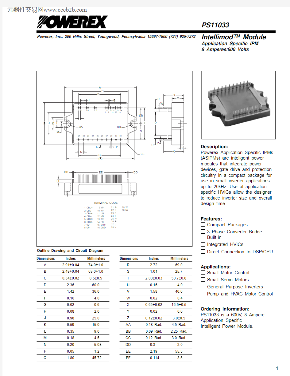
Dimensions
Inches Millimeters A 2.91±0.0474.0±1.0B 2.48±0.0463.0±1.0C 0.34±0.028.5±0.5D 2.3660.0E 1.4236.0F 0.16 4.0G 0.020.6H 0.08 2.0J 0.9825.0K 0.5915.0L 0.359.0M 0.18 4.5N 0.20 5.08P 0.05 1.2Q
1.80
45.72
Dimensions
Inches Millimeters R 2.7269.0S 1.0125.7T 2.00±0.0350.7±0.8
U 0.16 4.0V 1.5840.0W 0.020.4X 0.65±0.0216.5±0.5
Y 0.020.6Z 0.12±0.02 3.0±0.5AA 0.18 Rad. 4.5 Rad.BB 0.09 Rad. 2.25 https://www.doczj.com/doc/4c7211587.html, 0.12 Rad. 3.0 Rad.DD 0.8 2.0EE 2.1955.5FF
0.114
3.5
Outline Drawing and Circuit Diagram
Powerex, Inc., 200 Hillis Street, Youngwood, Pennsylvania 15697-1800 (724) 925-7272
PS11033
Intellimod? Module
Application Specific IPM
8 Amperes/600 Volts
Absolute Maximum Ratings, T j = 25°C unless otherwise specified
Characteristics Symbol PS11033Units Power Device Junction T emperature*T j-20 to 125°C Storage Temperature T stg-40 to 125°C Case Operating Temperature (See T C Measure Point Illustration)T C-20 to 100°C Mounting Torque, M4 Mounting Screws—13in-lb Module Weight (Typical)— 70Grams Isolation Voltage**V ISO2500Volts *The indicated values are specified considering the safe operation of all the parts within the ASIPM. The maximum rating for the ASIPM power chips (IGBT & FWDi) is T j < 150.
**60 Hz sinusoidal AC applied between all terminals and the base plate for 1 minute.
IGBT Inverter Sector
Supply Voltage (Applied between P2 - N2)V CC450Volts Supply Voltage, Surge (Applied between P2 - N2, Surge-Value)V CC(surge)500Volts Each IGBT Collector-Emitter Static Voltage (Applied between P2-U.V.W, U.V.W-N2)V P or V N600Volts Each IGBT Collector-Emitter Switching Voltage V P(S) or V N(S)600Volts (Applied between P2-U.V.W, U.V.W-N2 (Pulse))
Each IGBT Collector Current, T C = 25°C, “( )” means I C Peak Value±I C(±I CP)±8 (±16)Amperes
Converter Sector
Repetitive Peak Reverse Voltage V RRM800Volts Recommended AC Input Voltage E a220Vrms DC Output Current (3-phase Rectifying Circuit)I DC10 A Surge (Non-repetitive) Forward Current (1 Cycle at 60Hz, Peak Value Non-repetitive)I FSM100A
I2t for Fusing (Value for One Cycle of Surge Current)I2t42A2s
Control Sector
Supply Voltage V D,V DB-0.5 ~ 20Volts Input Signal Voltage V CIN-0.5 ~ 7.5Volts Fault Output Supply Voltage V FO-0.5 ~ 7.5Volts Fault Output Current I FO15mA DC-Link IGBT Current Signal Amp Output Current I AMP1mA
PS11033
Intellimod ? Module
Application Specific IPM 8 Amperes/600 Volts
Powerex, Inc., 200 Hillis Street, Youngwood, Pennsylvania 15697-1800 (724) 925-7272Electrical and Mechanical Characteristics, T j = 25°C unless otherwise specified
Characteristics
Symbol
Test Conditions
Min.
Typ.
Max.
Units
IGBT Inverter Sector
Collector-Emitter Saturation Voltage V CE(sat)I C = 8A, T j = 25°C, V D = V DB = 15V ,—
—
2.9
Volts
Input = ON (Shunt Voltage Drop Not Included)
Diode Forward Voltage V EC T j = 25°C, -I C = 8A —— 2.9Volts Converter Diode Voltage
V FR T j = 25°C, I FR = 5A —— 1.5Volts Converter Diode Reverse Current I RRM V R = V RRM , T j = 125°C
——8mA Switching Times
on C(on)CC C j off D DB C(off)
on off rr
Short Circuit Endurance (Output, Arm, and @V CC ≤ 400V , Input = 5V → 0V (One-shot),? No Destruction
Load Short-Circuit Modes) -20
°C ≤ T j(start) ≤ 125°C,? F O Output by Protection Operation
13.5V ≤ V D = V DB ≤ 16.5V Switching SOA
@V CC ≤ 400V , Input = 5V → 0V ,? No Destruction
T j ≤ 125°C, I C < OC T rip Level,? No Protecting Operation 13.5V ≤ V D = V DB ≤ 16.5V
? No F O Output T C Measure Point
C
Powerex, Inc., 200 Hillis Street, Youngwood, Pennsylvania 15697-1800 (724) 925-7272
PS11033
Intellimod? Module
Application Specific IPM
8 Amperes/600 Volts
Electrical and Mechanical Characteristics, T j = 25°C unless otherwise specified
Characteristics Symbol Test Conditions Min. Typ.Max.Units
Control Sector
Circuit Current (Average)I D T j = 25°C, V D = 15V, V IN = 5V——50mA
I DB T j = 25°C, V D = V DB = 15V, V IN = 5V——5mA Input ON Threshold Voltage V th(on)0.8 1.4 2.0Volts Input OFF Threshold Voltage V th(off) 2.5 3.0 4.0Volts Input Pull-up Resistor Ri Applied between—50—k?
Input Terminal-inside Power Supply
PWM Input Frequency f PWM T C≤ 100°C, T j≤ 125°C1—15kHz Arm Shoot-through Blocking Time*t DEAD Relates to Corresponding Inputs 2.2——μS
T C = -20°C ~ 100°C
Input Interlock Sensing t int Relates to Corresponding Input—100—ns Inverter DC-link IGBT Current V amp 100%I C = I OP(100%), V D = 15V, T j = 25°C 1.5 2.0 2.5Volts Sense Voltage Output Signal** V amp 200%I C = I OP(200%), V D = 15V, T j = 25°C 3.0 4.0 5.0Volts Inverter DC-link IGBT Current V amp 250%I C = I OP(250%), V D = 15V 5.0——Volts Sense Voltage Output Limit** V amp 0%I C = I OP(0%), V D = 15V—50100mV Over-Current Trip Level OC8.510.616.0Amperes
OC j
Short-Circuit Trip Level SC—16.0—Amperes
SC
Trip Level UV D11.012.013.0Volts Supply Circuit Reset Level UV Dr11.512.513.5Volts Under-Voltage DB C j
Protection Reset Level UV DBr10.611.312.1Volts Delay Time t dV—10—μS Fault Output Pulse Width***t FO T j = 25°C 1.0 1.8—mS Fault Output Current***I Fo(H)Open Collector Output——1μA
Fo(L)
* The dead-time has to be set externally by the CPU; it is not part of the ASIPM internal functions.
**Refer ro the graph on next page.
***Fault output signalling is given only when the internal OC, SC, and UV protection circuits are activated. The OC, SC and UV protection (and fault output) operate for the lower arms only. The OC and SC protection fault output is given in a pulse format while that of UV protection is maintained thrpughout the duration of the under-voltage condition.
PS11033
Intellimod ? Module
Application Specific IPM 8 Amperes/600 Volts
Powerex, Inc., 200 Hillis Street, Youngwood, Pennsylvania 15697-1800 (724) 925-7272Thermal Characteristics
Characteristic Symbol Condition Min. Typ.Max.Units Junction to Case
R th(j-c)Q Each IGBT —— 4.1°C/Watt R th(j-c)D Each FWDi —— 6.1°C/Watt R th(j-c)DR
Each Converter —— 4.8°C/Watt Contact Thermal Resistance
R th(c-f)
Case to Fin Per Module.—
—
0.074
°C/Watt
Thermal Grease Applied
Recommended Conditions for Use
Characteristic Symbol Condition
Min.Typ.Value Units Supply Voltage V CC
Applied across P2-N2 Terminals —300400Volts Control Supply Voltage
V D Applied between V D -GND 13.515.016.5Volts V DB
Applied between CBU+ & CBU-,13.5
15.0
16.5
Volts
CBV+ & CBV-, CBW+ & CBW-Control Supply dv/dt dV D /dt, dV DB /dt
-1—1V/μs Input ON Voltage V CIN(on)Applied between 0—0.8Volts CIN(off)P P P N N N Module Case Operating Temperature T C ——100°C PWM Input Frequency
f PWM T C ≤ 100°C, T j ≤ 125°C ——15kHz Allowable Minimum Input On-pulse Width t XX 1——μS Arm Shoot-through Blockin
g Time
t DEAD
Relate to Corresponding Inputs
2.2
—
—
μS
C U R R E N T S E N S
E V O L T A G E
O U T P U T S I G N A L ,V A M P , (V O L T S )
INVERTER DC-LINK IGBT CURRENT ANALOG SIGNALING (TYPICAL)
5
100
20043210300
ACTUAL LOAD PEAK CURRENT, (%), (I C = I O X ?2 )
PS11033
Intellimod ? Module
Application Specific IPM 8 Amperes/600 Volts
Powerex, Inc., 200 Hillis Street, Youngwood, Pennsylvania 15697-1800 (724) 925-7272
2
1
12
–
+–+–+
V D
U P V P W U N V N W F V Functional Block Diagram