The Panasas ActiveScale Storage Cluster –Delivering Scalable High Bandwidth Storage
- 格式:pdf
- 大小:195.18 KB
- 文档页数:10
3 A message box displays while the RAID group is beingcreated.When the RAID group is complete, the lower panel displays the RAID group.4The DVRAID group begins to rebuild. Double click on yourRAID group in the lower panel to see more detail such as the status of the rebuild. Wait until the rebuild is complete before sending data to the storage.Creating a custom RAID setup1After selecting Custom RAID setup in the ConfigurationTool RAID wizard, select the options to configure the new RAID group.•RAID Group Name : Assign a name to the RAID group or use the one assigned by the Configuration Tool. The name must be unique and no more than 14 characters.•RAID Group Level: Select a RAID group level from the drop-down box.•RAID Group Interleave: Select an interleave value. The default value is 128KB.2Click Next .3Select the disk devices in the top panel and drag them intothe device area in the bottom panel.4If you want the RAID group to be presented as one virtualdisk (partition), click Finish.If you want more than one virtual disk (partition): a.Click Next.b.Select one of the following:•leave as one partition •partition by count •partition by size c.Click Finish.5 A confirmation dialog box asks you to confirm theconfiguration you have chosen. Click Yes .6If you selected either RAID 4 or RAID 5 configuration, yourRAID group begins to rebuild. Double click on your RAID group in the lower panel to see more detail such as the status of the rebuild. Wait until the rebuild is complete before sending data to the storage.Additional RAID featuresRefer to the ATTO Utilities Manual for instruction on:•Creating Hot Spares•Changing RAID configurations •Enabling event notificationATTO Technology, Inc.155 CrossPoint ParkwayAmherst, New York 14068 USA Tel (716) 691-1999Fax (716) 691-9353Sales support:****************Technical support: Monday -- Friday, 8am-8pm EST*********************© 2007 ATTO Technology, Inc. All rights reserved. All brand or product names are trademarks of their respective holders.No part of this document may be reproduced in any form or by any means without the express written permission of ATTO Technology, Inc.9/2007 PRMA-0396-000ExpressSAS RAID Adapter Getting Started GuideThank you for purchasing the ATTO ExpressSAS RAID Adapter. This guide gives you the basics for installing and configuring your adapter. For more information, refer to the ExpressSAS RAID Adapter Installation and Operation Manual and the ATTO Utilities Manual . Examine the contents of your ExpressSAS packing box. If any of these items are missing, contact your ATTO authorized sales representative.•RAID adapter•ATTO ExpressSAS CD including drivers, user manuals and utilities (Installation CD)•An optional low-profile bracket and its installation procedure• A warranty and registration cardTo install and use the ATTO ExpressSAS RAID adapter you need• A computer with an available x8 or x16 PCI Express expansion slot. The ExpressSAS adapter has been optimized for x8 electrical slots. Check your computer’s documentation.•The complete ATTO ExpressSAS RAID adapter package•SAS/SATA storage, cables and connectors1Install and load driversDrivers for Windows®, Mac® OS X and Linux® are supplied on the Installation CD.The Installation CD splash screen.Windows1.1Power on your system.1.2Insert the Installation CD. The installation guide appears.If the guide does not appear, navigate to the batch file Autorun on the Installation CD and click on it.1.3Click on Windows Drivers .1.4Click on Windows x86 Drivers for 32-bit systems orWindows x64 Drivers for 64-bit systems. If you do not know which version to select, contact your system administrator or refer to your operating system manual.1.5Click on the menu item containing the words InstallDriver for the version of Windows you are using.1.6Follow the on-screen instructions to complete the driverinstallation.1.7Continue to 2 Install configuration software .OS X1.1Power on your system.1.2Insert the Installation CD.1.3After it mounts, open the ExpressSAS volume.1.4Select the Drivers folder.1.5Launch the installer.1.6Follow the on-screen instructions.1.7Continue to 2 Install configuration software .LinuxExpressSAS RAID adapters are not supported under Linux kernel 2.4.1.1Power on your system. 1.2Log in as root .1.3Verify that the kernel header files, usually included withthe Linux kernel development package, are installed.1.4Insert the Installation CD.1.5Mount the CD to your chosen mount point such as/mnt/cdrom.1.6Open your File Browser and browse to/mnt/cdrom/Linux/Drivers.1.7Click on the esasraid driver lnx_drv_esasraid_XXX.tgzand copy it to a directory such as /usr/src .1.8Open a Terminal session.rm a tio nS to ra g e to b e m a d e in to a n e w R A ID g ro u p1.9Change to the directory where you stored the esasraiddriver.1.10Extract the driver source: tar xfz lnx_drv_esasraid_XXX .tgz . The driver files will be extracted to a directory called lnx_drv_esasraid_ XXX .1.11Change the directory to lnx_drv_esasraid_ XXX .1.12Compile and install the driver using make install . Thedriver is now installed and ready to use.1.13Add the following line to /etc/modprobe.conf after installingthe driver: alias scsi_hostadapterX esasraid where X is the next available adapter number.1.14Continue to 2 Install configuration software .2Install configuration softwareThe ATTO Configuration Tool provides an effective and efficient mechanism to configure your adapter and RAID storage.You must have Java 1.5 JRE installed to use the software.The latest runtime for Windows and Linux can beobtained from /javase/downloads/index.jsp.The latest OS X build can be obtained through Software Update . Java 1.5 is only available in 10.4.1 and later.Windows2.1Using the command line prompt, verify that Java VirtualMachine (Java) version 1.5 or later is installed.2.2From the installation CD introductory screen, click onWindows Applications.2.3Click on Install ATTO Configuration Tool. 2.4Launch the installer.2.5Follow the on-screen instructions until the installationcompletes.2.6Continue to 3 Install the RAID adapter .OS X2.1Check Software update to ensure that the latest Javaupdates have been applied. 2.2Open the ExpressSAS volume.2.3Select the Configuration Tool folder.2.4Launch the Configuration Tool.2.5Follow the on-screen instructions until the installationcompletes.2.6Continue to 3 Install the RAID adapter .Linux2.1Verify in the terminal window that the installed Java VirtualMachine (Java) is from Sun by typing java -version . The GNU version JVM that is installed by default does not work with the installer.2.2In the File Browser window, browse to /mnt/cdrom/Linux/Configuration Tool .2.3Double click lnx_app_configtool_ XXX.bin.2.4Follow the on-screen instructions until the installationcompletes.2.5Continue to 3 Install the RAID adapter .3Install the RAID adapterAdditional information is available in the ExpressSAS RAID Adapter Installation and Operation Manual found on the Installation CD.3.1Power down the computer and unplug the computer from allpower sources.3.2Open the computer case.3.3Insert the ATTO ExpressSAS RAID adapter into any openx8 or x16 PCI Express expansion slot. Secure the adapter into the enclosure.If you have questions about how to install an expansion card in your system, consult your computer’s documentation.3.4Close the computer case.3.5If you have an ExpressSAS R348, continue to 4ExpressSAS R348 only ; otherwise, continue to 5 Install 4ExpressSAS R348 onlyBy default the ExpressSAS R348 is configured as a 4x internal port and a 4x external port. To use both internal ports instead of using the internal/external port combination:4.1Power on your computer.4.2Launch the ATTO Configuration Tool.4.3From the left-hand panel Device Listing , expand all theelements in the hosts tree.4.4Find the ExpressSAS adapter you are installing and click onthe Channel 1 entry in the tree.4.5 A new screen appears in the right panel. Change the PortConfiguration from 4 Intrn, 4 Extrn to 8 Internal .4.6Click on Commit .4.7Exit the Configuration Tool application.4.8Power down the computer and unplug the computer from allpower sources.4.9Continue to 5 Install SAS/SATA storage .5Install SAS/SATA storage5.1Connect your SAS/SATA storage to the ATTO ExpressSASRAID adapter•Use SFF-8088 external connectors for both models.•For SATA, use cables which are no longer than 1 meter. For SAS, use cables which are no longer than 7 meters.Consult with your storage vendor for the proper connectors and cables to interface with your storage.5.2Plug in your computer and storage and power them on.5.3Continue to 6 Create RAID groups .6Create RAID groupsThe Configuration Tool screens are similar for all operating systems.6.1Launch the ATTO Configuration Tool. The Welcome screenappears.6.2From the left-hand panel Device Listing , expand all theelements in the hosts tree.6.3Click on ExpressSAS R3XX .6.4 A new set of tabs appears in the right panel. Click on theRAID tab.6.5The application scans for drives.6.6 A list of available drives appears. Devices are displayed inthe top panel and RAID groups and Hot Spares are displayed in the bottom panel.If you have not yet defined any RAID groups, selecting the RAID tab automatically starts a RAID wizard. The wizard is displayed in the bottom panel.If the RAID wizard does not start automatically, select the RAID Management menu item at the top of the screen, then select the Create RAID Group from the menu presented.6.7Select either Setup DVRAID or Custom RAID setup.Setting up DVRAID™ automaticallyDigital Video RAID (DVRAID) provides parity redundancy for your data. DVRAID is ATTO Technology proprietary technology which supports the editing of uncompressed 10-bit High Definition (HD) video and multiple streams of real-time, uncompressed Standard Definition (SD) video.The DVRAID wizard automatically sets up DVRAID using 6, 7, 12, 14 or 24 drives. If you do not have 6, 7, 12, 14 or 24 drives attached to the ExpressSAS RAID adapter, you cannot use the DVRAID wizard.1After selecting Set up DVRAID in the Configuration ToolRAID wizard, click on OK .2The ATTO ExpressSAS adapter firmware automatically usesall unassigned disks to create a DVRAID configuration. A confirmation dialog box asks you to confirm the configuration you have chosen. Click Yes .。
Panasas ActiveScale Storage Cluster(存储集群)目录◆摘要◆第一代存储体系结构●直接连接存储(DAS)●网络连接存储(NAS)●存储域网(SAN)◆Panasas ActiveScale体系结构:下一代存储设计●智能灵巧的指挥刀片(DirectBlades)和存储刀片(StorageBlades)◆Panasas ActiveScale文件系统●Panasas ActiveScale文件系统的基本操作●建立一个全局名字空间(Name space)●Panasas存储集群的基本操作◆用于负载均衡和高可用性的ActiveScale集群●动态负载均衡●用于容错和数据可靠性的集群◆Active RAID●Active Spares●PanActive管理器—前瞻的数据保护◆DirectFLOW存储刀片软件—将数据优化布局到物理介质上◆总结摘要Panasas ActiveScale存储集群,以其智能灵巧的存储,加速了Linux集群计算速度。
将并行文件系统与基于对象的存储相结合,Panasas存储集群戏剧性地提高了Linux集群环境的可管理性和性能。
系统有如下特点:1.将集群的操作一体化,最大限度地减少了管理时间。
2.提高了应用的数据吞吐率,使昂贵的集群资源得到最大的回报。
3.能无缝地集成到现有的数据中心基础设施中去,最大限度地保护了现有投资。
本文从技术上概括地描述了Panasas ActiveScale体系结构,以及Panasas ActiveScale存储集群是如何设计成下一代高可扩展,且易于管理的存储网络系统的。
第一代存储体系结构数据密集型的应用正在将传统的计算体系结构推向极限。
无论是绘制人类基因图,还是地球表面结构成像以找到新的能源储藏,或者是制作最新的巨型炸弹爆炸的栩栩如生的影片,这些应用需要极大的数据容量和吞吐率。
要满足这些要求,在计算方面,需要增长Linux计算集群。
The Dell EMC PowerSwitch S4048T -ON switch is the industry’s latest data center networking solution, empowering organizations to deploy modern workloads and applications designed for the open networking era.Businesses who have made the transition away from monolithicproprietary mainframe systems to industry standard server platforms can now enjoy even greater benefits from Dell T echnologies’ open networking platforms. By using industry-leading hardware and a choice of leading network operating systems to simplify data center fabric orchestration and automation, organizations can tailor their network to their unique requirements and accelerate innovation.These new offerings provide the needed flexibility to transform data centers. High-capacity network fabrics are cost-effective and easy to deploy, providing a clear path to the software-defined data center of the future with no vendor lock-in. The S4048T -ON supports the open source Open Network Install Environment (ONIE) for zero-touch installation of alternate network operating systems, including feature rich Dell EMC Networking OS9 and Dell EMC SmartFabric OS10.High density 1/10G BASE-T switchThe Dell EMC PowerSwitch S-Series S4048T -ON is a high-density 100M/1G/10G/40GbE top-of-rack (T oR) switch purpose-built for applications in high-performance data center and computing environments. Leveraging a non-blocking switching architecture, the S4048T-ON delivers line-rate L2 and L3 forwarding capacity within a conservative power budget. The compact S4048T-ON design provides industry-leading density of 48 dual-speed 1/10G BASE-T (RJ45) ports, as well as six 40GbE QSFP+ up-links to conserve valuable rack space and simplify the migration to 40Gbps in the data center core. Each 40GbE QSFP+ up-link can also support four 10GbE (SFP+) ports with a breakout cable. In addition, the S4048T-ON incorporates multiple architectural features that optimizedata center network flexibility, efficiency and availability, including I/O panel to PSU airflow or PSU to I/O panel airflow for hot/cold aisle environments, and redundant, hot-swappable power supplies and fans. S4048T -ON supports feature-rich Dell EMC Networking OS9 and Dell EMC SmartFabric OS10, VLT, network virtualization features such as VRF-lite, VXLAN Gateway and support for Dell Embedded Open Automation Framework.• The S4048T -ON is the only switch in the industry that supports traditional network-centric virtualization (VRF) and hypervisor centric virtualization (VXLAN). The switch fully supports L2 VXLAN gateway function and has hardware support for L3 • The S4048T-ON also supports Dell T echnologies’ EmbeddedOpen Automation Framework, which provides enhanced network automation and virtualization capabilities for virtual data center environments.• The Open Automation Framework comprises a suite of interrelated network management tools that can be usedtogether or independently to provide a network that is flexible, available and manageable while helping to reduce operational expenses.Key applicationsDynamic data centers ready to make the transition to software-defined environments• High-density 10Gbase-T T oR server access in high-performance data center environments • Lossless iSCSI storage deployments that can benefit frominnovative iSCSI & DCB optimizations that are unique only to Dell Networking switches • When running the Dell EMC Networking OS9, Active Fabric™ implementation for large deployments in conjunction with the Dell EMC Z-Series, creating a flat, two-tier, nonblocking 10/40GbE data center network design:• High-performance SDN/OpenFlow 1.3 enabled with ability to inter-operate with industry standard OpenFlow controllers • As a high speed VXLAN Layer 2 Gateway that connects the hypervisor based ovelray networks with nonvirtualized infrastructure Key features - general• 48 dual-speed 1/10GbE (SFP+) ports and six 40GbE (QSFP+) uplinks (totaling 72 10GbE ports with breakout cables) with OS support • 1.44Tbps (full-duplex) non-blocking switching fabric delivers line-rate performance under full load with sub 600ns latency I/O panel to PSU airflow or PSU to I/O panel airflow • Supports the open source ONIE for zero-touch installation of alternate network operating systems • Redundant, hot-swappable power supplies and fans DELL EMC POWERSWITCH S4048T-ON SWITCHEnergy-efficient 10GBASE-T top-of-rack switch optimized for data center efficiency•Key features with Dell EMC Networking OS9• Scalable L2 and L3 Ethernet switching with QoS and a fullcomplement of standards-based IPv4 and IPv6 features,including OSPF, BGP and PBR (Policy Based Routing) support • VRF-lite enables sharing of networking infrastructure andprovides L3 traffic isolation across tenants• Increase VM Mobility region by stretching L2 VLAN within oracross two DCs with unique VLT capabilities like Routed VLT, VLT Proxy Gateway• VXLAN gateway functionality support for bridgingthe nonvirtualized and the virtualized overlay networks with line rate performance• Embedded Open Automation Framework adding automatedconfiguration and provisioning capabilities to simplify themanagement of network environments• Supports Puppet agent for DevOps• Modular Dell EMC Networking OS software delivers inherentstability as well as enhanced monitoring and serviceabilityfunctions• Enhanced mirroring capabilities including 1:4 localmirroring, Remote Port Mirroring (RPM), andEncapsulated Remote Port Mirroring (ERPM). • Rate shaping combined with flow based mirroring enables the user to analyze fine grained flows• Jumbo frame support for large data transfers• 128 link aggregation groups with up to 16 members per group, using enhanced hashing• Converged network support for DCB, with priority flow control (802.1Qbb), ETS (802.1Qaz), DCBx and iSCSI TLV• S4048T-ON supports RoCE and Routable RoCE to enable convergence of compute and storage on Active Fabric• User port stacking support for up to six units and unique mixed mode stacking that allows stacking of S4048-ON with S4048T-ON to provide combination of 10G SFP+ and RJ45 ports in a stack1/10G BASE-T cabling distancesCable T ype 1G BASE-T 10G BASE-TCat 6 UTP100m (330 ft) 55m (180 ft)Cat 6 STP100m (330 ft) 100m (330 ft)Cat 6A UTP100m (330 ft) 100m (330 ft)Cat 7100m (330 ft) 100m (330 ft)Product DescriptionS4048T S4048T, 48x 10GBASE-T, 6x QSFP+, 2x AC PSU, 2x fans, I/O Panel to PSU Airflow S4048T, 48x 10GBASE-T, 6x QSFP+, 2x AC PSU, 2x fans, PSU to I/O Panel AirflowRedundant power supplies S4048T, AC Power Supply, I/O Panel to PSU Airflow S4048T, AC Power Supply, PSU to I/O Panel AirflowFans S4048T Fan Module, I/O Panel to PSU Airflow S4048T Fan Module, PSU to I/O Panel AirflowOptics Transceiver,40GE QSFP+ Short Reach Optic,850nm wavelength,100-150m reach on OM3/OM4 Transceiver, 40GbE QSFP+ ESR, 300m reach on OM3 / 400m on OM4Transceiver, 40GbE QSFP+ PSM4 with 1m pigtail to male MPO SMF, 2km reach Transceiver, 40GbE QSFP+ PSM4 with 5m pigtail to male MPO SMF, 2km reach Transceiver, 40GbE QSFP+ PSM4 with 15m pigtail to male MPO SMF, 2km reach Transceiver, 40GbE QSFP+ LR4, 10km reach on SMFTransceiver, 40GbE QSFP+ to 1G Cu SFP adapter, QSA1 meter QSFP+ to QSFP+ OM3 MTP Fiber Cable. Requires QSFP+ Optics3 meter QSFP+ to QSFP+ OM3 MTP Fiber Cable. Requires QSFP+ Optics5 meter QSFP+ to QSFP+ OM3 MTP Fiber Cable. Requires QSFP+ Optics7 meter QSFP+ to QSFP+ OM3 MTP Fiber Cable. Requires QSFP+ Optics10 meter QSFP+ to QSFP+ OM3 MTP Fiber Cable. Requires QSFP+ Optics25 meter QSFP+ to QSFP+ OM3 MTP Fiber Cable. Requires QSFP+ Optics50 meter QSFP+ to QSFP+ OM3 MTP Fiber Cable. Requires QSFP+ Optics75 meter QSFP+ to QSFP+ OM3 MTP Fiber Cable. Requires QSFP+ Optics100 meter QSFP+ to QSFP+ OM3 MTP Fiber Cable. Requires QSFP+ OpticsProduct DescriptionCables Cable, QSFP+ to QSFP+, 40GbE Passive Copper Direct Attach Cable, 0.5 MeterCable, QSFP+ to QSFP+, 40GbE Passive Copper Direct Attach Cable, 1 MeterCable, QSFP+ to QSFP+, 40GbE Passive Copper Direct Attach Cable, 3 MeterCable, QSFP+ to QSFP+, 40GbE Passive Copper Direct Attach Cable, 5 MeterCable, QSFP+ to QSFP+, 40GbE Passive Copper Direct Attach Cable, 7 MeterCable, QSFP+, 40GbE, Active Fiber Optical Cable, 10 Meters (No optics required)Cable, QSFP+, 40GbE, Active Fiber Optical Cable, 50 Meters (No optics required)Cable, 40GbE QSFP+ to 4 x 10GbE SFP+, Active Optical Breakout CableCable, 40GbE (QSFP+) to 4 x 10GbE SFP+ Passive Copper Breakout Cable, 0.5 Meters Cable, 40GbE (QSFP+) to 4 x 10GbE SFP+ Passive Copper Breakout Cable, 1 MeterCable, 40GbE (QSFP+) to 4 x 10GbE SFP+ Passive Copper Breakout Cable, 3 MetersCable, 40GbE (QSFP+) to 4 x 10GbE SFP+ Passive Copper Breakout Cable, 5 MetersCable, 40GbE (QSFP+) to 4 x 10GbE SFP+ Passive Copper Breakout Cable, 7 MetersCable, 40GbE MTP (QSFP+) to 4xLC Optical Connectors, 1M(QSFP+,SFP+ Optics REQ,not incl) Cable, 40GbE MTP (QSFP+) to 4xLC Optical Connectors, 3M(QSFP+,SFP+ Optics REQ,not incl) Cable, 40GbE MTP (QSFP+) to 4xLC Optical Connectors, 5M(QSFP+,SFP+ Optics REQ,not incl) Cable, 40GbE MTP (QSFP+) to 4xLC Optical Connectors, 7M(QSFP+,SFP+ Optics REQ,not incl)Software L3 Dell EMC Networking OSS4048T: Dell EMC Networking software license operating system software license for advanced L3 features, latest versionS4048T: Dell EMC Networking software licenseDell EMC Networking OS operating system software license, latest versionNote: in-field change of airflow direction only supported when unit is powered down and all fan andpower supply units are replaced with airflow moving in a uniform directionSupported operating systems Big Switch Networks Switch Light OSDell EMC Networking OS9 and Dell EMC SmartFabric OS10 Pluribus OSTechnical specifications48 fixed 10GBase-T ports supporting 100M/1G/10G speeds6 fixed 40 Gigabit Ethernet QSFP+ ports1 RJ45 console/management port withRS232 signaling1 USB 2.0 type A to support mass storage device1 Micro-USB 2.0 type B Serial Console Port1 8 GB SSD ModuleSize: 1RU, 1.71 x 17.09 x 18.11”(4.35 x 43.4 x 46 cm) (H x W x D)Weight: 23 lbs (10.43kg)ISO 7779 A-weighted sound pressure level:65 dB at 77°F (25°C)Power supply: 100–240V AC 50/60HzMax. thermal output: 1568 BTU/hMax. current draw per system:4.6 A at 460W/100VAC,2.3 A at 460W/200VACMax. power consumption: 460 WattsT ypical power consumption: 338 WattsMax. operating specifications:Operating temperature: 32°F to 113°F(0°C to 45°C)Operating humidity: 5 to 90% (RH),non-condensingMax. non-operating specifications:Storage temperature: –40°F to 158°F(–40°C to 70°C) condensingRedundancyHot swappable redundant powerHot swappable redundant fansPerformance GeneralSwitch fabric capacity:1.44Tbps (full-duplex)720Gbps (half-duplex)Forwarding Capacity: 1080 MppsLatency: 2.8 usPacket buffer memory: 16MBCPU memory: 4GBOS9 Performance:MAC addresses: 160KARP table 128KIPv4 routes: 128KIPv6 hosts: 64KIPv6 routes: 64KMulticast routes: 8KLink aggregation: 16 links per group, 128 groupsLayer 2 VLANs: 4KMSTP: 64 instancesVRF-Lite: 511 instancesLAG load balancing: Based on layer 2,IPv4 or IPv6 headersLatency: Sub 3usQOS data queues: 8QOS control queues: 12Egress ACL: 1KQoS: Default 3K entries scalable to 12KIEEE compliance with Dell EMC Networking OS9802.1AB LLDP802.1D Bridging, STP802.1p L2 Prioritization802.1Q VLAN T agging, Double VLAN T agging, GVRP802.1Qbb PFC802.1Qaz ETS802.1s MSTP802.1w RSTP802.1X Network Access Control802.3ab Gigabit Ethernet (1000BASE-T)802.3ac Frame Extensions for VLAN T agging802.3ad Link Aggregation with LACP802.3ae 10 Gigabit Ethernet (10GBase-X)with QSA802.3ba 40 Gigabit Ethernet (40GBase-SR4,40GBase-CR4, 40GBase-LR4) onoptical ports802.3u Fast Ethernet (100Base-TX)802.3x Flow Control802.3z Gigabit Ethernet (1000Base-X)with QSA802.3az Energy Efficient EthernetANSI/TIA-1057 LLDP-MEDForce10 PVST+Max MTU 9216 bytesRFC and I-D compliance withDell EMC Networking OS9General Internet protocols768 UDP793 TCP854 T elnet959 FTPGeneral IPv4 protocols791 IPv4792 ICMP826 ARP1027 Proxy ARP1035 DNS (client)1042 Ethernet T ransmission1305 NTPv31519 CIDR1542 BOOTP (relay)1812 Requirements for IPv4 Routers1918 Address Allocation for Private Internets2474 Diffserv Field in IPv4 and Ipv6 Headers2596 Assured Forwarding PHB Group3164 BSD Syslog3195 Reliable Delivery for Syslog3246 Expedited Assured Forwarding4364 VRF-lite (IPv4 VRF with OSPF, BGP,IS-IS and V4 multicast)5798 VRRPGeneral IPv6 protocols1981 Path MTU Discovery Features2460 Internet Protocol, Version 6 (IPv6)Specification2464 T ransmission of IPv6 Packets overEthernet Networks2711 IPv6 Router Alert Option4007 IPv6 Scoped Address Architecture4213 Basic T ransition Mechanisms for IPv6Hosts and Routers4291 IPv6 Addressing Architecture4443 ICMP for IPv64861 Neighbor Discovery for IPv64862 IPv6 Stateless Address Autoconfiguration 5095 Deprecation of T ype 0 RoutingHeaders in IPv6IPv6 Management support (telnet, FTP,TACACS, RADIUS, SSH, NTP)VRF-Lite (IPv6 VRF with OSPFv3, BGPv6, IS-IS)RIP1058 RIPv1 2453 RIPv2OSPF (v2/v3)1587 NSSA 4552 Authentication/2154 OSPF Digital SignaturesConfidentiality for2328 OSPFv2 OSPFv32370 Opaque LSA 5340 OSPF for IPv6IS-IS1142 Base IS-IS Protocol1195 IPv4 Routing5301 Dynamic hostname exchange mechanism for IS-IS5302 Domain-wide prefix distribution withtwo-level IS-IS 5303 3-way handshake for IS-IS pt-to-ptadjacencies5304 IS-IS MD5 Authentication5306 Restart signaling for IS-IS5308 IS-IS for IPv65309 IS-IS point to point operation over LANdraft-isis-igp-p2p-over-lan-06draft-kaplan-isis-ext-eth-02BGP1997 Communities2385 MD52545 BGP-4 Multiprotocol Extensions forIPv6 Inter-Domain Routing2439 Route Flap Damping2796 Route Reflection2842 Capabilities2858 Multiprotocol Extensions2918 Route Refresh3065 Confederations4360 Extended Communities4893 4-byte ASN5396 4-byte ASN representationsdraft-ietf-idr-bgp4-20 BGPv4draft-michaelson-4byte-as-representation-054-byte ASN Representation (partial)draft-ietf-idr-add-paths-04.txt ADD PATHMulticast1112 IGMPv12236 IGMPv23376 IGMPv3MSDP, PIM-SM, PIM-SSMSecurity2404 The Use of HMACSHA- 1-96 withinESP and AH2865 RADIUS3162 Radius and IPv63579 Radius support for EAP3580 802.1X with RADIUS3768 EAP3826 AES Cipher Algorithm in the SNMPUser Base Security Model4250, 4251, 4252, 4253, 4254 SSHv24301 Security Architecture for IPSec4302 IPSec Authentication Header4303 ESP Protocol4807 IPsecv Security Policy DB MIBdraft-ietf-pim-sm-v2-new-05 PIM-SMwData center bridging802.1Qbb Priority-Based Flow Control802.1Qaz Enhanced Transmission Selection(ETS)Data Center Bridging eXchange (DCBx)DCBx Application TLV (iSCSI, FCoE)Network management1155 SMIv11157 SNMPv11212 Concise MIB Definitions1215 SNMP Traps1493 Bridges MIB1850 OSPFv2 MIB1901 Community-Based SNMPv22011 IP MIB2096 IP Forwarding T able MIB2578 SMIv22579 T extual Conventions for SMIv22580 Conformance Statements for SMIv22618 RADIUS Authentication MIB2665 Ethernet-Like Interfaces MIB2674 Extended Bridge MIB2787 VRRP MIB2819 RMON MIB (groups 1, 2, 3, 9)2863 Interfaces MIB3273 RMON High Capacity MIB3410 SNMPv33411 SNMPv3 Management Framework3412 Message Processing and Dispatchingfor the Simple Network ManagementProtocol (SNMP)3413 SNMP Applications3414 User-based Security Model (USM) forSNMPv33415 VACM for SNMP3416 SNMPv23417 Transport mappings for SNMP3418 SNMP MIB3434 RMON High Capacity Alarm MIB3584 Coexistance between SNMP v1, v2and v34022 IP MIB4087 IP Tunnel MIB4113 UDP MIB4133 Entity MIB4292 MIB for IP4293 MIB for IPv6 T extual Conventions4502 RMONv2 (groups 1,2,3,9)5060 PIM MIBANSI/TIA-1057 LLDP-MED MIBDell_ITA.Rev_1_1 MIBdraft-grant-tacacs-02 TACACS+draft-ietf-idr-bgp4-mib-06 BGP MIBv1IEEE 802.1AB LLDP MIBIEEE 802.1AB LLDP DOT1 MIBIEEE 802.1AB LLDP DOT3 MIB sFlowv5 sFlowv5 MIB (version 1.3)DELL-NETWORKING-SMIDELL-NETWORKING-TCDELL-NETWORKING-CHASSIS-MIBDELL-NETWORKING-PRODUCTS-MIBDELL-NETWORKING-SYSTEM-COMPONENTMIBDELL-NETWORKING-TRAP-EVENT-MIBDELL-NETWORKING-COPY-CONFIG-MIBDELL-NETWORKING-IF-EXTENSION-MIBDELL-NETWORKING-FIB-MIBDELL-NETWORKING-FPSTATS-MIBDELL-NETWORKING-LINK-AGGREGATIONMIBDELL-NETWORKING-MSTP-MIBDELL-NETWORKING-BGP4-V2-MIBDELL-NETWORKING-ISIS-MIBDELL-NETWORKING-FIPSNOOPING-MIBDELL-NETWORKING-VIRTUAL-LINK-TRUNKMIB DELL-NETWORKING-DCB-MIBDELL-NETWORKING-OPENFLOW-MIB DELL-NETWORKING-BMP-MIB DELL-NETWORKING-BPSTATS-MIB Regulatory compliance SafetyCUS UL 60950-1, Second Edition CSA 60950-1-03, Second Edition EN 60950-1, Second EditionIEC 60950-1, Second Edition Including All National Deviations and Group Differences EN 60825-1, 1st EditionEN 60825-1 Safety of Laser Products Part 1: Equipment Classification Requirements and User’s GuideEN 60825-2 Safety of Laser Products Part 2: Safety of Optical Fibre Communication SystemsFDA Regulation 21 CFR 1040.10 and 1040.11EmissionsInternational: CISPR 22, Class AAustralia/New Zealand: AS/NZS CISPR 22: 2009, Class ACanada: ICES-003:2016 Issue 6, Class AEurope: EN 55022: 2010+AC:2011 / CISPR 22: 2008, Class AJapan: VCCI V-3/2014.04, Class A & V4/2012.04USA: FCC CFR 47 Part 15, Subpart B:2009, Class A RoHSAll S-Series components are EU RoHS compliant.CertificationsJapan: VCCI V3/2009 Class AUSA: FCC CFR 47 Part 15, Subpart B:2009, Class AAvailable with US Trade Agreements Act (TAA) complianceUSGv6 Host and Router Certified on Dell Networking OS 9.5 and greater IPv6 Ready for both Host and RouterUCR DoD APL (core and distribution ALSAN switchImmunityEN 300 386 V1.6.1 (2012-09) EMC for Network Equipment EN 55022, Class AEN 55024: 2010 / CISPR 24: 2010EN 61000-3-2: Harmonic Current Emissions EN 61000-3-3: Voltage Fluctuations and Flicker EN 61000-4-2: ESDEN 61000-4-3: Radiated Immunity EN 61000-4-4: EFT EN 61000-4-5: SurgeEN 61000-4-6: Low Frequency Conducted ImmunityDellTechnologies ServicesConsultingDell T echnologies Consulting Services provides industryprofessionals with a wide range of tools and the experience your need to design and execute plans to transform your business. DeploymentAccelerate technology adoption with ProDeploy Enterprise Suite. Trust our experts to lead deployments through planning, configuration and complex integrations.ManagementRegain control of operations with flexible IT management options. Our Residency Services help you adopt and optimize new technologies and our Managed Services allow you to outsource portions of your environment to us.SupportIncrease productivity and reduce downtime with ProSupportEnterprise Suite. Expert support backed by proactive and predictive artificial intelligence cationDell T echnologies Education Services help you develop the IT skills required to lead and execute transformational strategies. Get certified today.Learn more at/ServicesPlan, deploy, manage and support your IT transformation with our top-rated servicesLearn more at DellT /Networking。
As storage demands expand and processing loads grow, it becomes increasingly more difficult for administrators to achieve maximum performance from their applications. The newest line of Dell PowerEdge RAID Controller cards, built on the LSI ® SAS 3108 dual-core PowerPC ® RAID-on-Chip (ROC), offers unmatched I/O performance for database applications and streaming digital media environments.The PowerEdge RAID Controller (PERC) H730, with eight internal ports, delivers two PowerPC processor cores and a 72-bit DDR3 interface that drives 1GB non-volatile cache memory. You can deploy the PERC H730 in hard drive-based server environments for significant performance gains. If you are implementing hybrid server platforms based on solid-state storage, these next-generation PERCs exploit the potential of solid-state drives (SSDs) for unsurpassed performance and enterprise-class reliability.Enterprise data protectionStandard support for the most popular RAID levels, including RAID 5, RAID 6, RAID 50, RAID 60 and NV Cache, further strengthen the data-protection capabilities of the PERC H730. Dell’s NV Cache technology backs up the data to non-volatile memory in a power-loss event, and can store it safely for a nearly unlimited period of time. The H730 also supports non-RAID mode (pass-through) for applications managing storage independently.Intuitive RAID managementManaging the PERC H730 is easy using theintegrated Dell Remote Access Controller (iDRAC) with Lifecycle Controller. Without having to deploy an agent, IT admins can configure, deploy, update and monitor the PERC H730, via the GUI or through Dell’s CLI (known as RACADM). Additionally, Dell’s one-to-many OpenManage Essentials consoleallows the user to perform storage operations across multiple servers, including the RAID controllers as well as the physical disks in the PowerEdge system and external enclosures.Benefits include:• iDRAC automatically creates and executes jobs for each storage configuration operation • Customer can reboot the host OS automatically or schedule reboot for a later date.• PERC H730 supports real-time RAID monitoring and hardware inventory .iDRAC incorporates Dell OpenManage ™ Storage Services (OMSS) which provides the tools to efficiently manage PERC products, including apre-boot setup utility and a full spectrum of online RAID management utilities. This suite of applications allows administrators to adjust SAS or SATA topology views from the system host down to the logical and physical drive level. Extending to enterprise deployments, these tools can scale to easilyconfigure, monitor and manage RAID and JBOD volumes locally or over the LAN network.Dell PowerEdge RAID Controller H730PowerEdge RAID Controller H730• Eight internal ports• 72-bit DDR3 interface drives 1GB non-volatile cache memory • Unsurpassed performance and enterprise-class reliabilityEight-port 12Gbps PCI Express (PCIe) RAID controller supporting 3Gbps, 6Gbps and12Gbps SAS or SATA hard-disk or solid-state drives.FeaturePowerEdge RAID Controller H730 technical specificationSolution provided Value/performance RAID and non-RAID (pass-through) solution for high-density servers (1U or 2U) with the flexibility to use both SATA and SAS HDDs, SSDs, and pass-through drive configurations Physical dimensions 167.6 mm (6.6 in) x 64.4 mm (2.5 in) (MD2 low profile) Connectors Two internal HD Mini-SAS SFF8643Device support Up to 255 (SAS, SATA)Host bus type 8-lane, PCI Express 3.0 compliant Key RAID and data protection featuresRAID levels 0, 1, 5, 6RAID spans 10, 50, 60Non-RAID (Pass-through)Online Capacity Expansion (OCE)Online RAID Level Migration (RLM)Auto resume after power loss during array rebuild or reconstruction/RLM Check Consistency for background data integrity Physical disk power management (Dimmer Switch™)4K native sector support Workload profilesSupport for TRIM/UNMAP Commands for SAS/SATA SSDsNVRAM “Wipe” feature- protects proprietary data once card is decommissioned SED drive support Load balancingFast initialization for quick array setup Configurable stripe size up to 1MB SSD supportPatrol read for media scanning and repairing DDF compliant Configuration on Disk (COD)S.M.A.R.T. supportGlobal and dedicated hot spare with revertible hot-spare support: automatic rebuild, enclosure affinity, emergency SATARAID managementCTRL-RDell OpenManage Storage Services Additional management:UEFI (HII)CEMOperating temperature Maximum ambient temperature: 60°C Operating voltage +3.3VOptional SSD optimizationDell FastPath™ firmware feature: delivers high IOPs performance on SSD arrays Operating systemsMicrosoft ® Windows Server ® 2008 R2 SP1Microsoft Windows Server 2012Microsoft Windows Server 2012 R1 & R2Red Hat ® Enterprise Linux ® 5.8Red Hat Enterprise Linux 6.5SUSE ® Linux Enterprise Server 10 SP4SUSE Linux Enterprise Server 11 SP3Virtualization options:VMware ® ESXi 5.1VMware 6.0WarrantyUp to five-year warranty available for controller (up to the length of purchased system warranty) Three-year warranty for battery©2016 Dell Inc. All rights reserved. Dell, the DELL logo, the DELL badge, PowerEdge, and OpenManage are trademarks of Dell Inc. Other trademarks and trade names may be used in this document to refer to either the entities claiming the marks and names or their products. Dell disclaims proprietary interest in the marks and names of others. This document is for informational purposes only. Dell reserves the right to make changes without further notice to any products herein. The content provided is as is and without express or implied warranties of any kind. **Leasing and financing provided and serviced by Dell Financial Services L.L.C. or its affiliate or designee (“DFS”) for qualified customers. Offers may not be available or may vary in certain countries. Where available, offers may be changed without notice and are subject to product availability, credit approval, execution of documentation provided by and acceptable to DFS, and may be subject to minimum transaction size. Offers not available for personal, family or household use. Dell and the DELL logo are trademarks of Dell Inc.October 2016 | Version 1.1Dell_PowerEdge_H730_SpecSheetEnd-to-end technology solutionsReduce IT complexity, lower costs and eliminate inefficiencies by making IT and business solutions work harder for you. You can count on Dell for end-to-end solutions to maximize your performance and uptime. A proven leader in Servers, Storage and Networking, Dell Enterprise Solutions and Services deliver innovation at any scale. And if you’re looking to preserve cash or increase operational efficiency, Dell Financial Services™ has a wide range of options to make technology acquisition easy and affordable. Contact your Dell Sales Representative for more information.**Learn More at /PERC.。
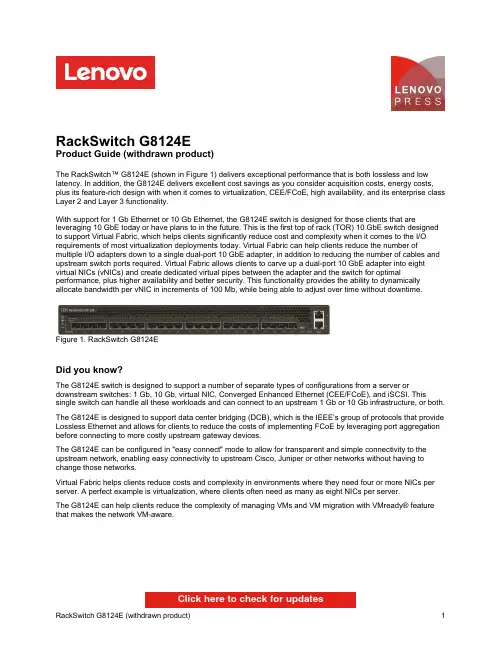
RackSwitch G8124EProduct Guide (withdrawn product)The RackSwitch™ G8124E (shown in Figure 1) delivers exceptional performance that is both lossless and low latency. In addition, the G8124E delivers excellent cost savings as you consider acquisition costs, energy costs, plus its feature-rich design with when it comes to virtualization, CEE/FCoE, high availability, and its enterprise class Layer 2 and Layer 3 functionality.With support for 1 Gb Ethernet or 10 Gb Ethernet, the G8124E switch is designed for those clients that are leveraging 10 GbE today or have plans to in the future. This is the first top of rack (TOR) 10 GbE switch designed to support Virtual Fabric, which helps clients significantly reduce cost and complexity when it comes to the I/O requirements of most virtualization deployments today. Virtual Fabric can help clients reduce the number of multiple I/O adapters down to a single dual-port 10 GbE adapter, in addition to reducing the number of cables and upstream switch ports required. Virtual Fabric allows clients to carve up a dual-port 10 GbE adapter into eight virtual NICs (vNICs) and create dedicated virtual pipes between the adapter and the switch for optimal performance, plus higher availability and better security. This functionality provides the ability to dynamically allocate bandwidth per vNIC in increments of 100 Mb, while being able to adjust over time without downtime.Figure 1. RackSwitch G8124EDid you know?The G8124E switch is designed to support a number of separate types of configurations from a server or downstream switches: 1 Gb, 10 Gb, virtual NIC, Converged Enhanced Ethernet (CEE/FCoE), and iSCSI. This single switch can handle all these workloads and can connect to an upstream 1 Gb or 10 Gb infrastructure, or both. The G8124E is designed to support data center bridging (DCB), which is the IEEE’s group of protocols that provide Lossless Ethernet and allows for clients to reduce the costs of implementing FCoE by leveraging port aggregation before connecting to more costly upstream gateway devices.The G8124E can be configured in "easy connect" mode to allow for transparent and simple connectivity to the upstream network, enabling easy connectivity to upstream Cisco, Juniper or other networks without having to change those networks.Virtual Fabric helps clients reduce costs and complexity in environments where they need four or more NICs per server. A perfect example is virtualization, where clients often need as many as eight NICs per server.The G8124E can help clients reduce the complexity of managing VMs and VM migration with VMready® feature that makes the network VM-aware.Click here to check for updatesover OM3 multimode fiber or up to 400 meters over OM4 multimode fiber with LC connectors. The 10GBASE-LR transceivers can support distances up to 10 kilometers on single mode fiber with LC connectors. For extended distances, the 10GBASE-ER transceivers can support distances up to 40 kilometers on single mode fiber with LC connectors.Table 3 lists the supported cables and transceivers.Table 3. Supported transceivers and direct-attach cablesDescription Partnumber Feature code(MTM 7309-HC6 / 7309-HC7)MaximumquantitysupportedSFP transceivers - 1 GbELenovo 1000BASE-T SFP Transceiver (does not support 10/100 Mbps)00FE333A5DL24 Lenovo 1000BASE-SX SFP Transceiver81Y1622326924 Lenovo 1000BASE-LX SFP Transceiver90Y9424A1PN24 SFP+ transceivers - 10 GbELenovo 10GBASE-SR SFP+ Transceiver46C3447505324 Lenovo 10GBASE-LR SFP+ Transceiver90Y9412A1PM24 Lenovo 10GBASE-ER SFP+ Transceiver90Y9415A1PP24 Optical cables for 1 GbE SFP SX and 10 GbE SFP+ SR transceiversLenovo 0.5m LC-LC OM3 MMF Cable00MN499ASR524 Lenovo 1m LC-LC OM3 MMF Cable00MN502ASR624 Lenovo 3m LC-LC OM3 MMF Cable00MN505ASR724 Lenovo 5m LC-LC OM3 MMF Cable00MN508ASR824 Lenovo 10m LC-LC OM3 MMF Cable00MN511ASR924 Lenovo 15m LC-LC OM3 MMF Cable00MN514ASRA24 Lenovo 25m LC-LC OM3 MMF Cable00MN517ASRB24 Lenovo 30m LC-LC OM3 MMF Cable00MN520ASRC24SFP+ passive direct-attach cables - 10 GbELenovo 0.5m Passive DAC SFP+ Cable00D6288A3RG24 Lenovo 1m Passive DAC SFP+ Cable90Y9427A1PH24 Lenovo 1.5m Passive DAC SFP+ Cable00AY764A51N24 Lenovo 2m Passive DAC SFP+ Cable00AY765A51P24 Lenovo 3m Passive DAC SFP+ Cable90Y9430A1PJ24 Lenovo 5m Passive DAC SFP+ Cable90Y9433A1PK24 Lenovo 7m Passive DAC SFP+ Cable00D6151A3RH24 SFP+ active direct-attach cables - 10 GbELenovo 1m Active DAC SFP+ Cable95Y0323A25A24 Lenovo 3m Active DAC SFP+ Cable95Y0326A25B24 Lenovo 5m Active DAC SFP+ Cable95Y0329A25C24 Lenovo 1m Active DAC SFP+ Cable (replaces 95Y0323)00VX111AT2R24 Lenovo 3m Active DAC SFP+ Cable (replaces 95Y0326)00VX114AT2S24 Lenovo 5m Active DAC SFP+ Cable (replaces 95Y0329)00VX117AT2T24Figure 2. Front panel of the RackSwitch G8124E Figure 3. Rear panel of the RackSwitch G8124ENetwork cabling requirementsThe network cables that can be used with the switch are listed in Table 4.Table 4. G8124E network cabling requirementsTransceiver Standard Cable Connector 10 Gb Ethernet10GBASE-SR SFP+ Transceiver (46C3447)10GBASE-SR Up to 30 m with fiber optic cables supplied by Lenovo (seeTable 3); 850 nm OM3 multimode fiber cable up to 300 m orup to 400 m with OM4 multimode fiberLC10GBASE-LR SFP+Transceiver (90Y9412)10GBASE-LR1310 nm single-mode fiber cable up to 10 km LC10GBASE-ER SFP+Transceiver (90Y9415)10GBASE-ER1310 nm single-mode fiber cable up to 40 km LC Direct attach cable10GSFP+Cu SFP+ DAC cables up to 7 m (see Table 3)SFP+ 1 Gb Ethernet1000BASE-T SFPTransceiver (00FE333)1000BASE-T UTP Category 5, 5E, and 6 up to 100 meters RJ-451000BASE-SX SFP Transceiver (81Y1622)1000BASE-SX Up to 30 m with fiber optic cables supplied by Lenovo (seeTable 3); 850 nm multimode fiber cable up to 550 m (50 µ)or up to 220 m (62.5 µ)LC1000BASE-LX SFPTransceiver (90Y9424)1000BASE-LX1310 nm single-mode fiber cable up to 10 km LC Management ports1 GbE management ports1000BASE-T UTP Category 5, 5E, and 6 up to 100 meters RJ-45 RS-232 management port RS-232DB-9-to-mini-USB or RJ-45-to-mini-USB console cable(comes standard with the switch)Mini-USB WarrantyFigure 4. Virtual Fabric topologyFigure 5. G8124E top-of-rack switchFigure 6. Rack-optimized server aggregation: 1 GbE attached rack serversFigure 7. G8124E benefits for IP storage over 10 GbE Related publications and linksTrademarksLenovo and the Lenovo logo are trademarks or registered trademarks of Lenovo in the United States, other countries, or both. A current list of Lenovo trademarks is available on the Web athttps:///us/en/legal/copytrade/.The following terms are trademarks of Lenovo in the United States, other countries, or both:Lenovo®BladeCenter®Flex SystemIntelligent ClusterLenovo ServicesNMotion®NeXtScaleNeXtScale System®RackSwitchSystem x®ThinkServer®VMready®iDataPlex®The following terms are trademarks of other companies:Hyper-V® and Microsoft® are trademarks of Microsoft Corporation in the United States, other countries, or both. Other company, product, or service names may be trademarks or service marks of others.。

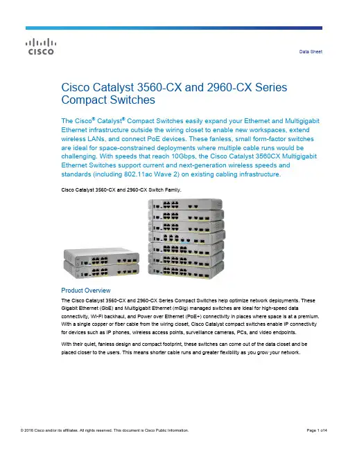
Data Sheet Cisco Catalyst 3560-CX and 2960-CX Series Compact SwitchesThe Cisco® Catalyst® Compact Switches easily expand your Ethernet and Multigigabit Ethernet infrastructure outside the wiring closet to enable new workspaces, extend wireless LANs, and connect PoE devices. These fanless, small form-factor switches are ideal for space-constrained deployments where multiple cable runs would be challenging. With speeds that reach 10Gbps, the Cisco Catalyst 3560CX Multigigabit Ethernet Switches support current and next-generation wireless speeds and standards (including 802.11ac Wave 2) on existing cabling infrastructure.Cisco Catalyst 3560-CX and 2960-CX Switch Family.The Cisco Catalyst 3560-CX and 2960-CX Series Compact Switches help optimize network deployments. These Gigabit Ethernet (GbE) and Multigigabit Ethernet (mGig) managed switches are ideal for high-speed data connectivity, Wi-Fi backhaul, and Power over Ethernet (PoE+) connectivity in places where space is at a premium. With a single copper or fiber cable from the wiring closet, Cisco Catalyst compact switches enable IP connectivity for devices such as IP phones, wireless access points, surveillance cameras, PCs, and video endpoints.With their quiet, fanless design and compact footprint, these switches can come out of the data closet and beplaced closer to the users. This means shorter cable runs and greater flexibility as you grow your network.Cisco Catalyst 3560-CX and 2960-CX Series Compact Switch Highlights●8 or 12 Gigabit Ethernet ports with line rate forwarding performance● 6 Gigabit Ethernet plus 2 Multigigabit Ethernet (100 Mbps/1/2.5/5/10 Gbps) ports with line rate forwardingperformance (selected model)●Gigabit and Multigigabit (100 Mbps/1/2.5/5/10 Gbps) copper, small form-factor pluggable (SFP) or10G SFP+ uplinks●Power over Ethernet Plus (PoE+) support with up to 240W of PoE budget●Power over Ethernet (PoE) pass-through enables the compact switch to draw Cisco Universal PoE(Cisco UPOE™) power from the wiring closet and pass it to end devices (selected model) with the additional option to be powered by auxiliary AC-DC or DC-DC power adapter●Cisco Instant Access mode to enable single point of management and simplify operation (selected models)●Advanced Layer 2 (LAN Base) and Layer 3 (IP Base) support with an option to upgrade to IP services●Fanless design and silent operation●Enhanced Limited Lifetime Warranty (E-LLW)Features and BenefitsLike the larger Cisco Catalyst switches typically used in wiring closets, the Cisco Catalyst Compact switches are a managed option for consistency across your LAN switching network. Unlike unmanaged switches and hubs, they provide advanced networking features for flexibility, security, and scale.Table 1 lists many of the Cisco Catalyst 3560-CX and 2960-CX switch features and benefits.Table 1. Compact Switch Features and Benefits SummaryPoE pass-through PoE pass-through gives the ability to power PoE end devices through drawing Cisco UPOE from the wiring closet. The Cisco Catalyst WS-C3560CX-8PT-S has eight downlink ports with two Cisco UPOE input ports that allow it to bepowered by another switch. These switches do not need a power supply and receive power over the uplink from anupstream PoE or Cisco UPOE device, providing deployment flexibility and availability. These switches are ideal forwiring-constrained and space-constrained applications.Management and OperationsCisco Instant Access Mode Available on Cisco Catalyst 3560-CX switches with 10 G SFP+ uplinks, this optional mode enables a single point of management and operation for campus networks. Multiple Cisco Catalyst 3560-CX compact switches with 10 G SFP+ uplinks can be connected to Cisco Catalyst 6500 or 6800 core switches, and the entire configuration can then work as a single extended switch with a common management domain.In this mode, compact switches inherit all the features of the Cisco Catalyst 6500 or 6800. Advanced Cisco Catalyst 6500 and 6800 features like MPLS and EVN can be extended to the access layer, so the Cisco Catalyst Instant Access solution can be deployed on all or a subset of the campus network.Cisco Network Plug ‘n Play (PnP) Network Plug-n-Play (PnP) is a secure, scalable solution that accelerates network device deployments by automating the installation and configuration of Cisco IOS software. The Cisco Catalyst 3560-CX and 2960-CX switches are‘Network-PnP Ready’ and can be used as part of the APIC-EM solution for automated switch deployments. This feature helps improve productivity, cut costs, reduce downtime, and enhance the user experience.Cisco Catalyst Smart Operations This comprehensive set of Cisco Catalyst technologies and Cisco IOS Software features simplify LAN deployment, configuration, and troubleshooting.●Cisco Smart Install enables the configuration of the Cisco IOS Software image and switch without userintervention.●Cisco Auto Smartports provides automatic configuration as end devices connect to the switch port, allowingautodetection and plug-and-play of the device onto the network. Interface templates containing configurations or policies that can be applied to ports are also supported.●Cisco Smart Troubleshooting is an extensive array of debug diagnostic commands and system health checks,including Generic Online Diagnostics (GOLD) and Onboard Failure Logging (OBFL).●Embedded Event Manager (EEM), supported on the Cisco Catalyst 3560-CX, provides real-time network eventdetection and onboard automation. You can adapt the behavior of your network devices to align with business needs.Cloud and System Management ●Cisco Prime® Infrastructure provides comprehensive network lifecycle management with an extensive library of features that automate initial and day-to-day management. Cisco Prime integrates hardware and software platform expertise and operational experience into a powerful set of workflow-driven configuration, monitoring, troubleshooting, reporting, and administrative tools.●Cisco Network Assistant is a PC-based, centralized network management and configuration application for small and medium-sized business (SMB) with up to 250 users. An intuitive GUI lets you easily apply common services across Cisco switches, routers, and access points.●Cisco Active Advisor is a cloud-based service that provides essential lifecycle information about your network inventory. Available by itself or as a component of other Cisco network management applications, it helps you reduce your network’s overall risk by keeping you up-to-date on the status of your products.Operational Simplicity ●Link Aggregation Control Protocol (LACP) for creating Ethernet channeling with devices that conform to IEEE 802.3ad. Similar to Cisco EtherChannel technology and PAgP.●Dynamic Host Configuration Protocol (DHCP) autoconfiguration of multiple switches through a boot server.●Multicast VLAN Registration (MVR) continuously sends multicast streams in a multicast VLAN. Isolates streamsfrom subscriber VLANs for bandwidth and security reasons.●Voice VLAN keeps voice traffic on a separate VLAN for easier administration and troubleshooting.●Cisco VLAN Trunking Protocol (VTP) supports dynamic VLANs and dynamic trunk configuration across allswitches.●Remote Switch Port Analyzer (RSPAN) allows administrators to remotely monitor ports in a Layer 2 switchnetwork from any other switch in the same network.●For enhanced traffic management, monitoring, and analysis, the Embedded Remote Monitoring (RMON) softwareagent supports four RMON groups (history, statistics, alarms, and events).SecurityCisco TrustSec® A suite of components that secures networks, data, and resources with policy-based access control, identity, and role-aware networking with the following elements:●Cisco TrustSec SXP support to simplify security and policy enforcement throughout the network. For moreinformation about Cisco TrustSec security solutions, visit /go/TrustSec.●Hardware on the Cisco Catalyst 3560-CX for IEEE 802.1AE MACsec for Layer 2, line-rate Ethernet dataconfidentiality and integrity on host-facing ports. Protects against man-in-the-middle attacks (snooping, tampering,and replay).●Flexible authentication that supports multiple authentication mechanisms including 802.1X, MAC AuthenticationBypass, and web authentication using a single, consistent configuration.●Monitor mode that creates a user-friendly environment for 802.1X operations.●RADIUS change of authorization and downloadable ACLs for comprehensive policy management.●802.1X supplicant with Network Edge Access Transport (NEAT) for extended secure access; compact switchesin the conference rooms have the same level of security as switches inside a locked wiring closet.Product DetailsSwitch ModelsThe Cisco Catalyst Compact Switches are available in nine switch models. They vary by whether they support both Layer 2 and Layer 3 services or Layer 2 services only; whether they support Power over Ethernet Plus (PoE+); by the number of Gigabit Ethernet and Multigigabit Ethernet ports; the aggregate power provided, and the type of cabling connections they support.Tables 2, 3, and 4 compare the available switch models and list the software package that ships by default with each model and how much PoE power is available for the downlink ports.Table 2. Cisco Catalyst 3560-X Compact Switch Models and Default SoftwareTable 3. C3560CX-8PT-S Switch PoE and PoE+ Power CapacityTable 4. Cisco Catalyst 2960-X Compact Switch Models and Default SoftwareNote: All four uplink ports (two copper and two fiber) can be used simultaneously and also as downlinks.Switch SoftwareCisco Catalyst 3560-CX compact switches ship with the IP Base version of Cisco IOS® Software. The 3560-CX switches can be upgraded to use the IP Services version of IOS Software with a right-to-use (RTU) License. The IP Base and IP Services feature set on Cisco Catalyst 3560-CX switches provides baseline enterprise services in addition to all LAN Base features. They support Layer 3 networking features, including support for routed access, Cisco TrustSec, media access control security (MACsec), and other advanced network services. The IP Services feature set provides full Layer 3 routing capabilities with Open Shortest Path First (OSPF), Border Gateway Protocol (BGP), Enhanced Internal Gateway Routing Protocol (EIGRP), Policy-Based Routing (PBR), Multicast Routing, and Virtual Routing and Forwarding (VRF) Lite.Cisco Catalyst 2960-CX Series compact switches ship with the LAN Base version of Cisco IOS Software. These switches deliver advanced Layer 2 switching with intelligent Layer 2 through 4 services for the network edge, such as voice, video, and wireless LAN services.Licensing and Software PolicyCustomers with Cisco Catalyst LAN Base and IP Base software feature sets will receive updates and bug fixes designed to maintain the compliance of the software with published specifications, release notes, and industry standards compliance as long as the original end user continues to own or use the product or for up to one year from the end-of-sale date for this product, whichever occurs earlier. This policy supersedes any previous warranty or software statement and is subject to change without notice.Product SpecificationsTable 5 provides hardware specifications for the Cisco Catalyst 3560-CX and 2960-CX compact switches.Table 5. Cisco Catalyst 3560-CX and 2960-CX Series Compact Switch HardwareTable 6 describes the power specifications for Cisco Catalyst 3560-CX and 2960-CX switches. Table 6. Power Specifications for Cisco Catalyst 3560-C and 2960-C Series Compact SwitchesTable 7 shows switch management and standards support.Table 7. Management and Standards Support for Cisco Catalyst 3560-CX and 2960-CX Series Compact Switches Description SpecificationManagement ●BRIDGE-MIB●CISCO-CABLE-DIAG-MIB●CISCO-CDP-MIB●CISCO-CLUSTER-MIB●CISCO-CONFIG-COPY-MIB●CISCO-CONFIG-MAN-MIB●CISCO-DHCP-SNOOPING-MIB●CISCO-ENTITY-VENDORTYPE-OID-MIB●CISCO-ENVMON-MIB●CISCO-ERR-DISABLE-MIB●CISCO-FLASH-MIB●CISCO-FTP-CLIENT-MIB●CISCO-IGMP-FILTER-MIB●CISCO-IMAGE-MIB●CISCO-IP-STAT-MIB●CISCO-LAG-MIB●CISCO-MAC-NOTIFICATION-MIB●CISCO-MEMORY-POOL-MIB●CISCO-PAGP-MIB●CISCO-PING-MIB●CISCO-POE-EXTENSIONS-MIB●CISCO-PORT-QOS-MIB●CISCO-PORT-SECURITY-MIB●CISCO-PORT-STORM-CONTROL-MIB●CISCO-PRODUCTS-MIB●CISCO-PROCESS-MIB●CISCO-RTTMON-MIB ●CISCO-TC-MIB●CISCO-TCP-MIB●CISCO-UDLDP-MIB●CISCO-VLAN-IFTABLE●RELATIONSHIP-MIB●CISCO-VLAN-MEMBERSHIP-MIB ●CISCO-VTP-MIB●ENTITY-MIB●ETHERLIKE-MIB●IEEE8021-PAE-MIB●IEEE8023-LAG-MIB●IF-MIB●INET-ADDRESS-MIB●OLD-CISCO-CHASSIS-MIB●OLD-CISCO-FLASH-MIB●OLD-CISCO-INTERFACES-MIB ●OLD-CISCO-IP-MIB●OLD-CISCO-SYS-MIB●OLD-CISCO-TCP-MIB●OLD-CISCO-TS-MIB●RFC1213-MIB●RMON-MIB●RMON2-MIB●SNMP-FRAMEWORK-MIB●SNMP-MPD-MIB●SNMP-NOTIFICATION-MIB●SNMP-TARGET-MIB●CISCO-SMI-MIB●CISCO-STP-EXTENSIONS-MIB ●CISCO-SYSLOG-MIB ●SNMPv2-MIB ●TCP-MIB●UDP-MIB●ePM MIBStandards ●IEEE 802.1D Spanning Tree Protocol●IEEE 802.1p CoS Prioritization●IEEE 802.1Q VLAN●IEEE 802.1s●IEEE 802.1w●IEEE 802.1x●IEEE 802.1AB (LLDP)●IEEE 802.3ad●IEEE 802.3af●IEEE 802.3ah(100BASE-X single/multimode fiber only)●IEEE 802.3x full duplex on 10BASE-T, 100BASE-TX, and1000BASE-T ports●IEEE 802.3 10BASE-T specification●IEEE 802.3u 100BASE-TX specification●IEEE 802.3ab 1000BASE-T specification●IEEE 802.3z 1000BASE-X specification ●100BASE-BX (SFP)●100BASE-FX (SFP)●100BASE-LX (SFP)●1000BASE-BX (SFP)●1000BASE-SX (SFP)●1000BASE-LX/LH (SFP)●1000BASE-ZX (SFP)●1000BASE-CWDM SFP 1470 nm ●1000BASE-CWDM SFP 1490 nm ●1000BASE-CWDM SFP 1510 nm ●1000BASE-CWDM SFP 1530 nm ●1000BASE-CWDM SFP 1550 nm ●1000BASE-CWDM SFP 1570 nm ●1000BASE-CWDM SFP 1590 nm ●1000BASE-CWDM SFP 1610 nm ●RMON I and II standards●SNMPv1, SNMPv2c, and SNMPv3RFC compliance ●RFC 768: UDP●RFC 783: TFTP●RFC 791: IP●RFC 792: ICMP●RFC 793: TCP●RFC 826: ARP●RFC 854: Telnet●RFC 951: Bootstrap Protocol●RFC 1542: BOOTP Extensions●RFC 959: FTP●RFC 1058: RIP Routing●RFC 1112: IP Multicast and IGMP●RFC 1157: SNMPv1●RFC 1166: IP Addresses●RFC 1253: OSPF Routing●RFC 1256: ICMP Router Discovery●RFC 1305: NTP●RFC 1492: TACACS+●RFC 1493: Bridge MIB●RFC 1542: Bootstrap Protocol●RFC 1583: OSPFv2●RFC 1643: Ethernet Interface MIB●RFC 1723: RIPv2 Routing●RFC 1757: RMON ●RFC 1812: IP Routing●RFC 1901: SNMPv2C●RFC 1902-1907: SNMPv2●RFC 1981: MTU Path Discovery IPv6●FRC 2068: HTTP●RFC 2080: RIP for IPv6●RFC 2131: DHCP●RFC 2138: RADIUS●RFC 2233: IF MIB●RFC 2236: IP Multicast●RFC 2328: OSPFv2●RFC 2273-2275: SNMPv3●RFC 2373: IPv6 Aggregatable Addrs●RFC 2453: RIPv2 Routing●RFC 2460: IPv6 protocol●RFC 2461: IPv6 Neighbor Discovery●RFC 2462: IPv6 Autoconfiguration●RFC 2463: ICMP IPv6●RFC 2474: DiffServ Precedence●RFC 2597: Assured Forwarding●RFC 2598: Expedited Forwarding●RFC 2571: SNMP Management●RFC 2740: OSPF for IPv6●RFC 3046: DHCP Relay Agent Information Option●RFC 3101, 1587: NSSAs●RFC 3376: IGMPv3●RFC 3580: 802.1x RADIUSNote: RFC, MIB and Standards compliance is dependent on IOS Level.Table 8 shows safety and compliance information.Table 8. Safety and Compliance SupportOrdering InformationTo place an order, consult Table 9 for ordering information and visit Cisco Commerce Workspace. Table 9. Ordering Information for Cisco Catalyst 3560-CX and 2960-CX Series Compact SwitchesWarranty InformationCisco Catalyst 3560-CX and 2960-CX Series Switches come with an enhanced limited lifetime hardware warranty that includes 90 days of Cisco Technical Assistance Center (TAC) support and next-business-day hardware replacement free of change (see Table 10 for details).Table 10. Enhanced Limited Lifetime Hardware WarrantyYour formal warranty statement, including the warranty applicable to Cisco software, appears in the Cisco information packet that accompanies your Cisco product. We encourage you to review carefully the warranty statement shipped with your specific product before use. Cisco reserves the right to refund the purchase price as its exclusive warranty remedy.Adding a Cisco technical services contract to your device coverage provides access to the Cisco Technical Assistance Center (TAC) beyond the 90-day period allowed by the warranty. It also can provide a variety of hardware replacement options to meet critical business needs, as well as updates for licensed premium Cisco IOS Software, and registered access to the extensive knowledge base and support tools.For additional information about warranty terms, visit /go/warranty.Cisco and Partner ServicesEnable the innovative, secure, intelligent edge using personalized services from Cisco and our partners. Through a discovery process that begins with understanding your business objectives, we help you integrate the next-generation Cisco Catalyst fixed switches into your architecture and incorporate network services onto thoseplatforms. Sharing knowledge and leading practices, we support your success every step of the way as you deploy, absorb, manage, and scale new technology.Choose from a flexible suite of support services (Table 11), designed to meet your business needs and help you maintain high-quality network performance while controlling operational costs.Table 11.Technical Services Available for Cisco Catalyst 3560-CX and 2960-CX Series Compact SwitchesCisco CapitalFinancing to Help You Achieve Your ObjectivesCisco Capital can help you acquire the technology you need to achieve your objectives and stay competitive. We can help you reduce CapEx. Accelerate your growth. Optimize your investment dollars and ROI. Cisco Capital financing gives you flexibility in acquiring hardware, software, services, and complementary third-party equipment. And there’s just one predictable payment. Cisco Capital is a vailable in more than 100 countries. Learn more .Learn MoreFor more information, contact your Cisco sales account rep or visit /go/compactswitches .Printed in USAC78-733229-07 12/16。
10 Key Benefits of Panduit SmartZone™ DCIM Solutions A s organizations demand more from their IT infrastructure while requiring ever more efficient operations, data centers have become one of the primary areas of focus for improvement. During the first 40 years of data centers, the focus was simply on ensuring operational continuity and stability . However , in the last few years, there is a new focus on making data centers more efficient and more responsive to the changing organizations they support.Panduit SmartZone™ Solutions provide comprehensive intelligent DCIM software, hardware, and supporting services. This offering allows organizations to works synergistically with the normal IT operations lifecycle of “Plan/Deploy/Operate” to address operational issues. The following “T op 10” list offers examples of some of the key top-of-mind issues that SmartZone™ Solutions addresses.#1 – Provide Highly Granular Data on Power Usage in the Data Center – When it comes to managing a data center , having accurate and specific information that tracks actual power usage at the rack, group, or functional level is critical to effective operations. This information is delivered by SmartZone™ Solutions, and allows IT operations to monitor , display , and document power utilization, as well as identify rising power and/or temperature threshold concerns to drive efficiencies and prevent downtime. Further , this information provides actionable data that can be used to identify underutilized or “stranded” power capacity that can potentially be reclaimed to maximize existing IT resources.#2 – Automated Asset Tracking & Reconciliation – In most data centers there are regular changes to the devices that are deployed. In the past when changes were less frequent and there were fewer devices, manual or simple tracking tools were acceptable - but this is no longer the case. Using manual or rudimentary asset tracking solutions often results in inaccurate, outdated information and the need for audits, which can cost up to $40,000 each time. SmartZone™ Solutions provide complete and up to date asset tracking of connected infrastructure devices. Automated asset tracking is critical to optimizing costs such as softwareIntelligent DCIM has become the strategic descriptor of the move toward three prime goals:• Efficiency (Energy and Operational)• Uptime• Capacitylicensing or maintenance contracts where accurate hardware inventory drives spending cuts. Another important element of this capability is to identify unused, underutilized, or inefficient devices that could be repurposed or replaced to lower operating costs. In addition, this capability simplifies the reconciliation of overall asset tracking so that the tool alerts you to changes, not the other way around.#3 – Intelligently Deploy Assets – As new storage, servers, and network equipment are deployed in the data center, the question of where to physically locate them becomes very important. Overloading the electrical, connectivity, or cooling capacity in a specific location can result in unplanned downtime, a situation no one wants. However, without accurate information on the actual rack location details, what resource capacity exists, and where environmental support is assured, installing new hardware can be risky.Panduit SmartZone™ Solutions gather this crucial information to allow for faster andmore successful hardware installation and provides guidance for patching, resulting insubstantial time-savings in IT operations.#4 – Reclaim Stranded Capacity – As pressure builds to support business needs, it results in data center growth to support IT demands. These growing needs are causing datacenters to fill up quickly, and organizations to spend CAPEX on building or expandingexisting resources. The ability to identify and use every bit of your existing data center to forgo or delay costly new builds as long as possible is very valuable. The PanduitSmartZone™ Solutions provide visibility of actual power, cooling, space, and connectivity resources being utilized, as well as what is still available for use. This includes theability to identify “stranded capacity”, where full utilization of one or more resources is constrained by full consumption of one or more other resource in a rack or cabinet.For instance, one cabinet may be only using 50% of its available power consumptionbecause there is no available physical space left to deploy devices. Insight gained from DCIM software provides actionable data for IT to possibly reconfigure or decommission devices and balance out available resource consumption. This allows maximum overall utilization to ideally postpone the need for new data center builds or expansions. Without proper visibility, making uninformed changes creates serious risk of negatively impacting operations. SmartZone™ solutions provide the accurate, current and specific information necessary to understand current capacity resources, and help to identify strandedcapacity that could be reclaimed.#5 – Real-time Environmental Monitoring – Many data centers now operate closer to their environmental limits than was typically the case in the past. Further, many of the most modern servers and other hardware devices will operate at different utilizationlevels, changing their environmental impact constantly. This situation requires real-time monitoring of all aspects of the data center environment. The Panduit offering isdesigned to not only provide real-time temperature and humidity metrics, but to deliver this data with a level of granularity necessary to allow IT operations to effectivelymanage all zones of the data center, and prevent downtime. This SmartZone™ Solution capability also creates the information necessary to develop trending analysis so thataction can be taken before any situation becomes critical. SmartZone™ Solutions offer industry-leading wireless monitoring and cooling control solutions that work withextensive power, IT asset and connectivity management for a complete DCIM solution.#6 – Improve Uptime & Reliability – Ensuring that the data center remains fully operational is likely the single most important aspect of IT operations, and PanduitSmartZone™ Solutions helps to minimize downtime risks. By monitoring power,environmental, and connectivity conditions around the clock, SmartZone™ Solutions can actively identify rising temperature concerns, unplanned connectivity disruptions, oreven unauthorized access to cabinets or network ports. DCIM software can then sendimmediate notification alerts of events and locations for immediate resolution andlowered mean time to repair (MTTR). This capability is essential to ensure that IT is able to meet SLAs.#7 – Reduce Mean Time to Repair (MTTR) – Despite the relatively high reliability of most data center components, systems or other elements of the data center occasionally need replacement. The ability to do this as quickly and effectively as possible is critical to operations, and a key part of Panduit SmartZone™ Solutions. The solution starts byproviding real-time monitoring to identify where problems may exist. The system then accurately identifies failed or compromised hardware, and where it is physically located.And, as security becomes ever more important, SmartZone™ Solutions can identify and discover where authorized, erroneous or unauthorized changes to network connections have occurred, facilitating repair or addressing other possible problems with networkhardware devices.#8 – Faster Identification of Unauthorized or Compromised Network Access –The network is highly important in nearly every aspect of IT operations. Having a full and complete picture of how the network is functioning and any changes in network use and access is critical. Panduit SmartZone™ Solutions allow faster identification of any changes or interruption to the network that impacts the switches. The solution provides real-time monitoring of the switches, with the ability to set custom parameters to prevent “false”positives, or to highlight only specific conditions. There is also automated discovery of any changes, including new devices, unauthorized devices, and any changed devices.SmartZone™ also offers enhanced control of physical access to data center assets toprotect from unintentional or unauthorized access to devices.#9 – Calculating Accurate PUE Metrics – There are multiple initiatives and compliance demands that require more accurate information about data center operations,especially around Power Usage Effectiveness (PUE). This is where the Panduit solution truly shines. Starting with a design that integrates data center metrics into the overall building usage data, SmartZone™ Solutions provide more granular and accurate datathan most other approaches. These solutions provide data on power consumptionbeyond the Power Distribution Unit (PDU), a comparison between building providedpower and IT used power, and full support for PUE2 Category 3, which provides the most rigorous metrics.#10 – Identify & Document Power and Cooling Cost Reductions – As organizations demand more cost cutting and budget efficiency from IT operations, there is a need to showcase the actual savings that have occurred. SmartZone™ Solutions provide consistent and accurate measurement of the data center environment that is regularly gathered, delivering the time sequence information necessary to show savings. The management console also provides a holistic perspective of data center operations to ensure all of this data is well integrated and can be viewed cohesively. There is also complete andcomprehensive documentation on the actual efficiency and power reductions that have been implemented which is critical for compliance programs. Finally, the data is highly granular, providing the detail needed to show how savings were achieved and the insight to understand these savings.For more information visit: /dcim。
IBM Spectrum Scale技术和架构详解IBM高端存储最新产品为DS8884、DS8886和DS8888。
闪存系统最新产品,以FlashSystem 900为硬件基础,包装了Flash System V9000、A9000和A9000R,今天我们重点讨论下IBM Spectrum Scale软件定义存储产品。
IBM Spectrum Scale完全继承GPFS,也称作Elastic Storage,兼容AIX, Linux and Windows Server操作系统,支持IBM POWER, Intel或AMD Opteron 服务器和z Systems。
Spectrum Scale具有良好的可扩展性、闪存加速性能,以及基于策略的自动存储分层功能(从闪存、磁盘到磁带)。
Spectrum Scale 为所有数据提供单一文件命名空间,提供Swift/S3对象服务和Openstack 接口、大数据等存储服务接口。
IBM Spectrum Scale是高性能、高扩展性的文件、对象、块和大数据分析的存储软件,具备随地存储、运行和数据访问能力。
Spectrum Scale 在GPFS的基础上增加了Hadoop大数据、对象等能力,在存储功能上有了增强,具备丰富的特性、如Cache加速、生命周期管理、统一命名空间、多站点等;同时支持加密等特性和软硬件解耦部署云集成可以和IBM Spectrum controller SDS控制器、SmartCloud Virtual Storage Center业务编排、 SmartCloud Storage Access云存储服务引擎、Openstack、IBM Cloud云平台和管理平台集成。
存储服务能力提供丰富的业务访问能力,如文件接口 (POSIX, NFS, CIFS), 对象接口 (S3, SWIFT) 、大数据接口 Hadoop Distributed File System (HDFS)等等,支持集中部署和分部署多Region部署。
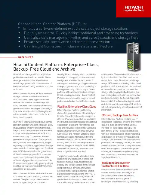
• • • • • DATA SHEE TUnstructured data growth and application proliferation continue to accelerate. These developments lead to increased server and storage sprawl, with numerous silos of infrastructure supporting traditional and new workloads.Hitachi Content Platform (HCP) is an object storage software solution that connects data producers, users, applications and devices into a central cloud storage plat-form. It enables users to better understand, govern and control the degree of mobility of their data, as well as to identify insights and extract value for data-driven decisions and faster time to market.HCP lets IT organizations and cloud service providers securely and cost-effectively store, share, protect, preserve and analyze data. Beyond its efficiency, ease of use and ability to store data at massive scale, HCP auto-mates day-to-day IT operations like data governance and protection. This approach readily evolves to changes in scale, scope, regulatory compliance, applications, storage, server and cloud technologies over the life of data. HCP also automates the governance of data to ensure proper retention, access control, encryption and disposal of data, while simplifying e-discovery and search. In IT environments where data grows quickly or must live for years or even indefinitely, these capabilities are invaluable.Hitachi Content Platform eliminates the need for a siloed approach to storing unstructured content. The platform provides massive scale, multiple storage tiers, powerfulHitachi Content Platform: Enterprise-Class, Backup-Free Cloud and Archivesecurity, Hitachi reliability, cloud capabilities, broad protocol support, multitenancy and configurable attributes for each tenant. It can support a wide range of applications on a single physical cluster and is backed by a thriving community of third-party software partners. With access to a robust ecosys-tem of cloud applications, Hitachi Content Platform can solve a wide range of current problems and adapt to meet future needs.Flexible, Enterprise-Class CloudHitachi Content Platform multitenancy divides the physical cluster into a variety of tenants. These tenants can be assigned to different IP networks and further subdivided into thousands of namespaces for additional organization of content, more refined poli-cies, and robust access control. Openness is also a hallmark of HCP . It has powerful native REST and Amazon Simple Storage Service (S3) based interfaces, permitting seamless WAN or LAN access for new and existing Web 2.0 and mobile applications. Further, it supports the NFS, SMB, SMTP and WebDAV protocols, and offers dual-stack support for IPV4 and IPV6.The platform can handle all kinds of data and almost any application. It offers high reliability, massive scale, seamless data mobility and storage across private clouds and public cloud services, encryption, access control, easy provisioning, charge-back measurement and more. The HCP G series access nodes allow organizations greater flexibility to support mixed work-loads with varying performance and scalerequirements. These nodes virtualize capac-ity from Hitachi Content Platform S series nodes, local drives, Fibre Channel storage arrays, NFS shares and leading public cloud providers. HCP drastically reduces total cost of ownership and provides cost-effective storage with geographically dispersed era-sure coding data protection for content that must remain behind the firewall. Such attri-butes enable IT to take advantage of cloud and deliver a whole new range of IT services, without compromising security and control of information.Efficient, Backup-Free ArchiveHitachi Content Platform enables your IT organization to protect, preserve and retrieve data in a more efficient manner, without the need for tape-based backups. The high density of HCP storage is enhanced with built-in compression, single instancing and support for a variety of media to keep storage costs in control. With dynamic data protection, data integrity checks, data reten-tion enforcement, erasure coding and many other technologies to preserve and protect content, HCP delivers compliance-quality data protection. It eliminates the need for tape-based backups.Intelligent Structure for Unstructured File DataHitachi Content Platform enables trusted content mobility with full visibility of all the control points where data enters, exits and exists across a global ITlandscape. It optimizes cost by providingWith HCP , you have access to metadata and content search tools that enable more elegant and automated queries for faster, more accu-rate results. Through these features you can gain a better understanding of the content of stored files, how content is used and how objects may be related to one another. This understanding can help you to enable more intelligent automation, along with big data analytics based on best-in-class metadata architecture.Hitachi Content Platform provides morecapabilities, flexibility, configurability and input options for you to take advantage of cloud in your own way. It simplifies management via automation to ensure efficiency, reliability, data mobility and accessibility of your organizations’ data. With HCP you can not only address today’s challenges around storing and protect-ing data, but also set yourself up for the next big thing.provide erasure coding to deliver long-term compliance and protection at the lowest cost. There’s no need to learn any new datamovement procedures or processes. Using the HCP interface, you can orchestrateseamless and policy-based data movement to the HCP S series nodes to optimize agility and efficiency.HCP for Cloud ScaleHitachi Content Platform for cloud scale is designed for applications requiring hyperscale, high-performance and comprehensive S3 API compliance. Its novel microservicedesign enables massive scalability to support hundreds of nodes and trillions of objects, and also features rich, policy-driven management and data enrichment tools. Its globalnamespace allows for unified management across multiple on-premises and cloud deployments. Offering broad flexibility, HCP for cloud scale’s architecture is hardware agnostic. It can be deployed on “white box” servers, leading cloud platforms such as Amazon Elastic Compute Cloud (EC2), or Hitachi Unified Compute Platform using a variety of Linux distributions. HCP S series nodes provide ideal on-premises storage for HCP for cloud scale. HCP for cloud scale also supports any S3 storage endpoint, including Amazon ECS.the flexibility to maintain your critical data securely, on-premises or in public clouds. It automatically moves content based onbusiness value or your storage-related service level agreement to the most appropriate storage tier. For example, content can be moved to Hitachi Content Platform S series nodes or cloud storage services, including Amazon S3, Microsoft Azure, Google Cloud Storage or any other S3-enabled cloud.As shown in Figure 1:●●HCP G series nodes are access nodes.●●HCP S series nodes are optional and pro-vide massive scale.●●Fibre Channel storage and cloud are optional.Performance and Scale To Power Next-Gen Hybrid Data CentersHCP S Series NodesHitachi Content Platform S series nodes provide economical deep data storage and protection in a small footprint. They seamlessly extend your private or hybrid cloud and offload infrequently accessed content from valuable primary storage. These nodes deliver the scale and economics of the public cloud locally with large capacity drives and always-on, self-optimization processes to maintain data integrity, availability and durability. They alsoFigure 1. Flexibility of Hitachi Content PlatformVM = virtual machine, RDM = remote device management, KVM = kernel-based virtual machine, EB = exabyte All capacities raw. Usable capacity will vary based on data protection choices.TABLE 1. HITACHI CONTENT PLATFORM OFFERINGSHITACHI is a registered trademark of Hitachi, Ltd. Microsoft and Azure are trademarks or registered trademarks of Microsoft Corporation. All other trademarks, service marks and company names are properties of their respective owners.DS-125-U BTD March 2020Hitachi VantaraCorporate Headquarters 2535 Augustine DriveSanta Clara, CA 95054 USA | Contact Information USA: 1-800-446-0744Global: /contactHITACHI CONTENT PLATFORM IMPLEMENTATION SERVICEHitachi Vantara provides consulting, implementation, migration and replication services to help you bring the benefits of Hitachi content solutions to your business-driven IT environment. In this implementation service, we can help you address data growth challenges, manage unstructured data throughout its life cycle, enable mobility, cloud and converged infrastructure strategies, and harness the value of your data with sophisticated search and analytics. Complementary services include Hitachi Content Platform Replication Service and Hitachi Content Platform Migration Service.SSD = solid state disk, GbE = gigabit Ethernet, HDD = hard disk drive, RU = rack unit All capacities raw. Usable capacity will vary based on data protection choices. 1Total for both controllersTABLE 2. HITACHI CONTENT PLATFORM HARDWAREWe Are Hitachi VantaraWe guide our customers from what’s now to what’s next by solving their digital challenges. Working alongside each customer, we apply our unmatched industrial and digital capabilities to their data and applications to benefit both business and society.。
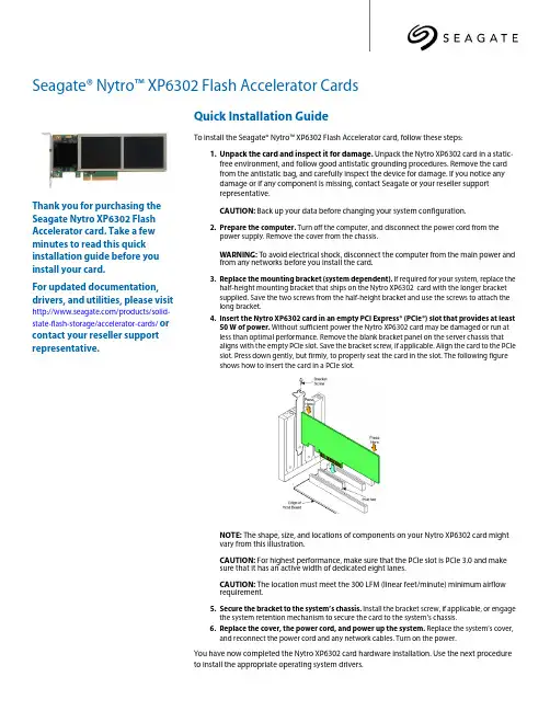
Seagate® Nytro™ XP6302 Flash Accelerator CardsThank you for purchasing the Seagate Nytro XP6302 Flash Accelerator card. Take a few minutes to read this quick installation guide before you install your card.For updated documentation, drivers, and utilities, please visit /products/solid-state-flash-storage/accelerator-cards/ or contact your reseller supportrepresentative.Quick Installation GuideTo install the Seagate® Nytro™ XP6302 Flash Accelerator card, follow these steps:1.Unpack the card and inspect it for damage. Unpack the Nytro XP6302 card in a static-free environment, and follow good antistatic grounding procedures. Remove the cardfrom the antistatic bag, and carefully inspect the device for damage. If you notice anydamage or if any component is missing, contact Seagate or your reseller supportrepresentative.CAUTION: Back up your data before changing your system configuration.2.Prepare the computer. Turn off the computer, and disconnect the power cord from thepower supply. Remove the cover from the chassis.WARNING: To avoid electrical shock, disconnect the computer from the main power and from any networks before you install the card.3.Replace the mounting bracket (system dependent). If required for your system, replace thehalf-height mounting bracket that ships on the Nytro XP6302 card with the longer bracketsupplied. Save the two screws from the half-height bracket and use the screws to attach the long bracket.4.Insert the Nytro XP6302 card in an empty PCI Express® (PCIe®) slot that provides at least50 W of power. Without sufficient power the Nytro XP6302 card may be damaged or run atless than optimal performance. Remove the blank bracket panel on the server chassis thataligns with the empty PCIe slot. Save the bracket screw, if applicable. Align the card to the PCIe slot. Press down gently, but firmly, to properly seat the card in the slot. The following figureshows how to insert the card in a PCIe slot.NOTE: The shape, size, and locations of components on your Nytro XP6302 card might vary from this illustration.CAUTION: For highest performance, make sure that the PCIe slot is PCIe 3.0 and makesure that it has an active width of dedicated eight lanes.CAUTION: The location must meet the 300 LFM (linear feet/minute) minimum airflowrequirement.5.Secure the bracket to the system’s chassis. Install the bracket screw, if applicable, or engagethe system retention mechanism to secure the card to the system’s chassis.6.Replace the cover, the power cord, and power up the system. Replace the system’s cover,and reconnect the power cord and any network cables. Turn on the power.You have now completed the Nytro XP6302 card hardware installation. Use the next procedure to install the appropriate operating system drivers.© 2015 Seagate Technology LLC. All rights reserved. Printed in USA. Seagate, Seagate Technology and the Wave logo are registered trademarks of Seagate Technology LLC in the United States and/or other countries. DuraWrite, Nytro, Fusion MPT, and SandForce are either trademarks or registered trademarks of Seagate Technology LLC or one of its affiliated companies in the United States and/or other countries. All other trademarks or registered trademarks are the property of their respective owners. Nytro products are not intended for use in life-support appliances, devices, or systems. Use of any Nytro product in such applications without written consent of the appropriate Seagate officer is prohibited. Seagate reserves the right to change, without notice, product offerings or specifications.Publication Number: 100765556, Rev. B, April 2015Windows Driver InstallationThe Seagate drivers for Windows Server® 2012 and Windows Server 2008 are available online. Download the latest Windows drivers from the Seagate website:1.Go to the following website:/products/solid-state-flash-storage/accelerator-cards/2.Click on Nytro XP6302 Flash Accelerator Card .3.Click Support , and click the driver you need.4.Download the driver files.5.Open the Windows Driver Configuration Utility file and follow the instructions to install the driver.Linux Driver InstallationSeagate provides open source drivers in the following ways:•Precompiled binaries to add to an existing installation using driver update disks or RPMs for selected distributions.•Fusion-MPT™ source to add or update any distribution.Download the latest Linux® drivers from the Seagate website.1.Go to the following website:/products/solid-state-flash-storage/accelerator-cards/2.Click on Nytro XP6302 Flash Accelerator Card .3.Click Support , and click the driver you need.4.Download the driver files and install the RPM files.FreeBSD Driver InstallationDownload the latest FreeBSD® drivers from the Seagate website.1.Go to the following website:/products/solid-state-flash-storage/accelerator-cards/2.Click on Nytro XP6302 Flash Accelerator Card .3.Click Support , and click the driver you need.4.Download the driver files and install the drivers.VMware ESXi5.1, ESXi 5.5Download the latest VMware® drivers from the Seagate website.1.Go to the following website:/products/solid-state-flash-storage/accelerator-cards/2.Click on Nytro XP6302 Flash Accelerator Card .3.Click Support , and click the driver you need.4.Download the driver files and unzip. Install the drivers.You have now completed the hardware and software installation for your Nytro XP6302 card.TECHNICAL SUPPORT For assistance installing, configuring, or using the Seagate Nytro XP6302 card, contact Seagate Technical Support: Submit a support ticket here: /Phone: 1-800-732-4283 (North America)+00-800-732-4283 (International) Website: 。
HostBusAdapter.TheQLE2460isenterpriseclass,4Gbps-to-PCIExpress®x4adapter.TheQLE2460deliversunprecedentedlevelsofperformanceandavailability,aswellasintelligentnetworkingfeaturesspecifictoenterpriseclassdatacenters. EnterpriseClassFeatures.TheQLE2460adapteristhehighestperformingandmostreliableadapterintheindustry.ItdeliversunmatchedperformanceleveragingasingleASICdesign,combiningarchitecturetodeliverover150,000IOPS,nearly800MBpsthroughput,andforPCIExpressx4busspeeds.Moreadapterprovidesnewintelligentstoragenetworkingfeaturesthatredefinetheenterpriseclassadapter,providingincreaseddataprotection,advancedframerouting,andenterprise-widemanagementcapabilities.Setup.Point-and-clickinstallationtheadaptersetupprocess.StorageadministratorsdeployadaptersacrossaSANusingstandardadaptermanagementtoolsdeviceutilities.TheQLE2460isfullycompatibleSMI-S,therebyallowingadministratorstomanageQLogicadaptersusingthird-partysoftwareapplications.ComprehensiveOSSupport.QLogicoffersthebroadestrangeofsupportforallmajoroperatingsystemstoensureOSandhardwareservercompatibility.Driversareavailableforallmajoroperatingsystemsandhardwareserverplatforms.AsingledriverstrategyperOSallowsstorageadministratorstoeasilydeployandmanageadaptersinheterogeneousSANconfigurations.Corporate Headquarters QLogic Corporation 26650 Aliso Viejo Parkway Aliso Viejo, CA 92656 949.389.6000 International Offices UK | Ireland | Germany | India | Japan | China | Hong Kong | Singapore | Taiwan© 2004–2010 QLogic Corporation. Specifications are subject to change without notice. All rights reserved worldwide. QLogic, the QLogic logo, and SANsurfer are registered trademarks of QLogic Corporation. AMD and Opteron are trademarks or registered trademark of Advanced Micro Devices, Inc. Apple, Mac OS, Power Mac, and Xserve are registered trademarks of Apple, Inc. Cisco is a registered trademark of Cisco Systems, Inc. Citrix and XenServer are trademarks or registered trademarks of Citrix Systems, Inc. Linux is a registered trademark of Linus Torvalds. Oracle is a registerd trademark of Oracle Corporataion. PCI Express is a registered trademark of PCI-SIG Corporation. Red Hat is a registered trademark of Red Hat, Inc. Solaris and OpenSolaris are trademarks or registered trademarks of Sun Microsystems, Inc. SPARC is a registered trademark of SPARC International, Inc. SUSE, Novell, and NetWare are registered trademarks of Novell, Inc. VMware, and ESX are trademarks or registered trademarks of VMware, Inc. Windows, Windows Server, and Windows Vista are registered trademarks of Microsoft Corporation. XenServer is a registered trademark of Citrix Systems, Inc. All other brand and product names are trademarks or registered trademarks of their respective owners. Informa-tion supplied by QLogic Corporation is believed to be accurate and reliable. QLogic Corporation assumes no responsibility for any errors in this brochure. QLogic Corporation reserves the right, without notice, to make changes in product design or specifications.。
Regulatory Model No. SP-2584Data SheetOneStor TMSP-3584Extensible Storage Platform (ESP)Features5U rack-mount enclosure stores up to 5 petabytes of data per rack, saving space in the data center •Certified 80 PLUS Platinum efficient power conversion and adaptive cooling technologyreduces power and cooling costs •Data center space savings + power and cooling cost savings = exceptionally low total cost of ownership•Ultra-dense, with up to 84 3.5” SAS hard disk drives or solid state drives per 5U enclosure •Unique drawer design provides extremely high density per rack unit, and provides easy access to hot swap drives•Capacity of 840Tb in 5U using 10Tb enterprise HDDs•Expansion capability up to 336 drives Dual 12Gb SAS I/O modules with integral data path redundancy•Maximum of 28.8 GB/s in a dual controller configurationThe proliferation of digital content in the enterprise has created increasingly complex and costly storage systems. These systems consume large amounts of energy and prevent companies from easily adapting their IT infrastructure as needs change. As the pace of change continues to accelerate, the evolution of storage technologies has become essential. OEMs and solution integrators need an extensible storage infrastructure that provides flexibility, reliability and energy efficiency to meet diverse application requirements. These include applications in digital media, in compliance retention and in data archival.The OneStor SP-3584 evolves the mature SP-2584 platform to 12G SAS while maintaining the prior architecture utilizing significant hardware reuse, a common management API and SBB 2.0 compatibility. This enables OEMs to accelerate market introduction of new technologies and also significantly simplifies development and testing of storage implementations while reducing overhead.Seagate Advancing 12Gb/s SASSeagate Advancing 12Gb/s SAS The Seagate implementation of 12Gb/s SAS offers a number of significant improvements to 6Gb/s SAS over and above the doubling of the data transfer rate from 6 Gb/s to 12 Gb/s. These include support and capabilities for managed cables, active and optical cables, universal ports, self configuration, and standardized zoning. Seagate supports 12Gb/s SAS in end-to-end configurations providing an effective maximum throughput of 14.4 GB/s per I/O module or 28.8 GB/s in a dual controller configuration, enough to support the highest performing solid state storage devices.Delivering a Versatile & Scalable ArchitectureAs a member of the OneStor family, the SP-3584 leverages the reuse of interchangeable I/O modules, a common enclosure management and SBB 2.0 compatibility. This enables OEMs to accelerate market introduction of new technologies and also significantly simplifies development and testing of storage implementations while reducing overhead.Assuring Robust Data AvailabilityThrough its intelligent Unified System Management (USM), OneStor safeguards data and ensures maximum availability. Users are able to leverage fault diagnosis and resolution capabilities, persistent error logging and monitoring. In addition, OneStor provides high availability features such as dual redundant PSUs, N+1 cooling modules, dual I/O modules and dual data paths to all drives.Customizing to Meet OEM Specific RequirementsOEMs can easily tailor each OneStor platform to meet end product requirements, including colored plastics, custom moldings, labeling, logo printing and product packaging.AMERICAS Seagate Technology LLC 10200 South De Anza Boulevard, Cupertino, California 95014, United States, 408-658-1000 ASIA/PACIFIC Seagate Singapore International Headquarters Pte. Ltd. 7000 Ang Mo Kio Avenue 5, Singapore 569877, 65-6485-3888EUROPE, MIDDLE EAST AND AFRICA Seagate Technology SAS 16–18, rue du Dôme, 92100 Boulogne-Billancourt, France, 33 1-4186 10 00© 2016 Seagate Technology LLC. All rights reserved. Printed in USA. Seagate, Seagate Technology and the Wave logo are registered trademarks of Seagate Technology LLC in the United States and/or other countries. Seagate OneStor is either trademarks or registered trademarks of Seagate Technology LLC or one of its affiliated companies in the United States and/or other countries. All other trademarks or registered trademarks are the property of their respective owners. When referring to drive capacity, one gigabyte, or GB, equals one billion bytes. Your computer’s operating system may use a different standard of measurement and report a lower capacity. In addition, some of the listed capacity is used for formatting and other functions, and thus will not be available for data storage. Actual data rates may vary depending on operating environment and other factors. The export or re-export of hardware or software containing encryption may be regulated by the U.S. Department of Commerce, Bureau of Industry and Security (for more information, visit ), andcontrolled for import and use outside of the U.S. Seagate reserves the right to change, without notice, product offerings or specifications. Issue 1.0 | 2017Take the next step: to learn more about Seagate ®Cloud Systems and Solutions visit /oem。
Brocade VDX 6740Switch Configuration Guide for EqualLogic SANs Dell Storage EngineeringJanuary 2015Revisions© 2015 Dell Inc. All rights reserved. Reproduction of this material in any manner whatsoever without the express written permission of Dell Inc. is strictly forbidden. For more information, contact Dell.Dell, the Dell logo, and the Dell badge and EqualLogic are trademarks of Dell Inc. Brocade® is a registered trademark of Brocade Communication Systems, Inc. and/or its affiliates in the U.S. and other countries.Table of contentsRevisions (2)1Introduction (4)1.1Audience (4)1.2Switch details (4)1.3Cabling diagram (5)2Dell recommended switch configuration (6)2.1Hardware configuration (6)2.2Delete startup configuration (6)2.3Configure Port Channel (7)2.4Configure Ports for LAG (7)2.5Configure Global LLDP settings to disable DCB (7)2.6Disable Ethernet Fabric on edge ports (7)2.7Enable Jumbo MTU (8)2.8Enable Switchport (8)2.9Enable link level flow control (802.3x) (8)2.10Configure Spanning tree on edge ports (8)2.11Disable LLDP iSCSI priority on Switch Ports (8)2.12Save configuration (8)2.13Configure additional switch (8)3Performance Tuning (9)4Configuring VCS ID and Rbridge-ID (10)Additional resources (11)1IntroductionThis document illustrates how to configure the Brocade VDX 6740 switch for use with EqualLogic™ PSSeries storage using Dell™ best practices. The recommended configuration uses Brocade link aggregationgroups (LAGs) for inter-switch connections.1.1AudienceThis switch configuration guide describes a verified configuration following Dell best practices for anEqualLogic iSCSI SAN and is intended for storage or network administrators and deployment personnel. 1.2Switch detailsThe table below provides an overview of the switch configuration.1.3Cabling diagramThe cabling diagram shown below represents the Dell recommend method for deploying your servers and EqualLogic arrays.Figure 1Cabling diagram2Dell recommended switch configurationThese steps show how to configure two Brocade VDX 6740 switches with a Brocade proprietary LAGinterconnect. The switches are interconnected using two 40Gb ports configured as the LAG links. 40GPort Upgrade license is required to use the 40G uplinks.2.1Hardware configuration1.Power on both switches2.Connect a serial cable to the management port.ing any terminal utility, open a serial connection session to the switch.4.Open your terminal emulator and configure it to use the serial port (usually COM1 but this mayvary depending on your system). Configure serial communications for 9600,N,8,1 and no flowcontrol.5.Connect the cables between switch 1 and switch 2 as shown in Figure 1. This will be used as yourBrocade LAG link.2.2Delete startup configurationsw0# copy default-config startup-configThis operation will modify your startup configuration. Do you want to continue?[y/n]:yWARN: "reload system" is required to have configuration changes take effect!sw0# reload systemWarning: This operation will cause the chassis to reboot andrequires all existing telnet, secure telnet and SSH sessions to berestarted.Are you sure you want to reboot the chassis [y/n]? y2.3Configure Port Channelsw0#configureEntering configure mode terminalsw0(config)# interface Port-channel 1sw0(config-Port-channel-1)# mtu 9216sw0(config-Port-channel-1)# switchportsw0(config-Port-channel-1)# switchport mode trunksw0(config-Port-channel-1)# qos flowcontrol tx off rx onsw0(config-Port-channel-1)# speed 40000sw0(config-Port-channel-1)# no shutdownsw0(config-Port-channel-1)# exit2.4Configure Ports for LAGsw0(config)# interface FortyGigabitEthernet 1/0/49-50sw0(conf-if-fo-1/0/49-50)# no fabric isl enablesw0(conf-if-fo-1/0/49-50)# no fabric trunk enablesw0(conf-if-fo-1/0/49-50)# channel-group 1 mode active type brocadesw0(conf-if-fo-1/0/49-50)# no ceesw0(conf-if-fo-1/0/49-50)# no lldp disablesw0(conf-if-fo-1/0/49-50)# no shutdownsw0(conf-if-fo-1/0/49-50)# exit2.5Configure Global LLDP settings to disable DCBThe below commands are issued to disable dcbx-tlv and iscsi-app tlv.sw0(config)#protocol lldpsw0(conf-lldp)#no advertise dcbx-iscsi-app-tlvsw0(conf-lldp)#no advertise dcbx-tlvsw0(conf-lldp)#exit2.6Disable Ethernet Fabric on edge portssw0(config)#interface TenGigabitEthernet 1/0/1-48sw0(conf-if-te-1/0/1-48)# no fabric isl enablesw0(conf-if-te-1/0/1-48)# no fabric trunk enablesw0(conf-if-te-1/0/1-48)# exit2.7Enable Jumbo MTUsw0(config)#interface TenGigabitEthernet 1/0/1-48sw0(conf-if-te-1/0/1-48)# mtu 9216sw0(conf-if-te-1/0/1-48)# exit2.8Enable Switchportsw0(config)#interface TenGigabitEthernet 1/0/1-48sw0(conf-if-te-1/0/1-48)# switchportsw0(conf-if-te-1/0/1-48)# switchport mode accesssw0(conf-if-te-1/0/1-48)# exit2.9Enable link level flow control (802.3x)sw0(config)#interface TenGigabitEthernet 1/0/1-48sw0(conf-if-te-1/0/1-48)# qos flowcontrol tx off rx onsw0(conf-if-te-1/0/1-48)# exit2.10Configure Spanning tree on edge portssw0(config)#protocol spanning-tree rstpsw0(config-rstp)#exitsw0(config)#interface TenGigabitEthernet 1/0/1-48sw0(conf-if-te-1/0/1-48)# spanning-tree edgeportsw0(conf-if-te-1/0/1-48)# exit2.11Disable LLDP iSCSI priority on Switch Portssw0(config)#interface TenGigabitEthernet 1/0/1-48sw0(conf-if-te-1/0/1-48)# no lldp disablesw0(conf-if-te-1/0/1-48)# no ceesw0(conf-if-te-1/0/1-48)# no lldp iscsi-prioritysw0(conf-if-te-1/0/1-48)# exit2.12Save configurationswitch#copy running-config startup-config2.13Configure additional switchRepeat the commands from Sections 2.1 through 2.12 to configure the second switch.3Performance TuningIn our testing of VDX 6740 with EqualLogic and using asymmetric flow control i.e. TX off RX on, thedefault buffer allocation of 280KB per port per queue didn’t yield optimum throughput and significant TCP retransmits were observed. But NOS version 5.0.1 has additional knobs to fine tune the buffers and addadditional buffer per port per queue. The following section shows how to configure the receive andtransmit buffers. Our testing indicated the optimal setting as 2MB for receive queue and 2MB for transmitqueue per port.sw0# configureEntering configuration mode terminalsw0(config)# rbridge-id 1sw0(config-rbridge-id-1)# qos tx-queue limit 2000sw0(config-rbridge-id-1)# qos rcv-queue limit 2000sw0(config-rbridge-id-1)# exitsw0(config)#4Configuring VCS ID and Rbridge-IDRefer to Brocade documentation for details on VCS and ethernet fabric. The following commands showsthe steps to configure the rbridge-id and VCS id to 2 on the second switch so that it doesn’t conflict withthe default value of 1 on Switch 1. VDX 6740 is in Fabric Cluster mode by default and configuration change is not required for the mode.sw0# show vcsConfig Mode : Local-OnlyVCS Mode : Fabric ClusterVCS ID : 1Total Number of Nodes : 1Rbridge-Id WWN Management IP VCS StatusFabric Status HostName--------------------------------------------------------------------------------------------------------------2 >10:00:50:EB:1A:2D:F2:64* 77.77.77.77 OnlineOnline sw0sw0# vcs vcsid 2This operation will change the configuration to default and reboot the switch.Do you want to continue? [y/n]:ysw0# vcs rbridge-id 2This operation will change the configuration to default and reboot the switch.Do you want to continue? [y/n]:y11SCG1020 | Brocade VDX 6740 Switch Configuration Guide for EqualLogic SANsAdditional resources is focused on meeting your needs with proven services and support. is an IT Community where you can connect with Dell Customers and Dell employees for the purpose of sharing knowledge, best practices, and information about Dell products and yourinstallations.Referenced or recommended Dell publications:∙Dell EqualLogic Configuration Guide:/techcenter/storage/w/wiki/equallogic-configuration-guide.aspx∙Dell EqualLogic Compatibility Matrix:/techcenter/storage/w/wiki/2661.equallogic-compatibility-matrix.aspxFor EqualLogic best practices white papers, reference architectures, and sizing guidelines for enterpriseapplications and SANs, refer to Storage Infrastructure and Solutions Team Publications at:∙http://dell.to/sM4hJT。
DS-A81024S/24024-slot Single Controller StorageIntroductionThe DS-A81 series is an economical and reliable Hybrid SAN (Storage Area Network) product. Hikvision Hybrid SAN product creates a network with access to data storage servers, and it inte grates Hikvision’s unique video direct streaming technology as well as supports IPSAN. Hybrid SAN system supports third-party cameras such as BOSCH, AXIS, SONY, Samsung, etc., and supports RTSP and ONVIF protocols, and extended data retention. With no recording server needed, Hikvision’s Hybrid SAN systems truly make applications simple, flexible, and budget-friendly.Key FeatureEconomical and Stable Hardware Platform●64-bit multi-core processor.● 4 to 64 GB high-speed cache.●PCI-E3.0 high-speed transmission channel,support 4×GbE or 2 ×10GbE is extendable●Five 10M/100M/1000M network interfaces.●Redundant design for key modules.●4U chassis model supports 24 HDDs.HDD Detection and Repair/RAID Optimization●Detection before operation.●Detection in operation.●Fault repair.●RAID 0, 1, 3, 5, 6, 10, 50.●Global and local hot spare.●Quick RAID building.●Capability of cascading upAdvanced Data Protection●Synchronous backup of key information in systemdisk and HDD.●RAID-based tamper-proof data technology.●Auto data synchronization between devices. Energy Efficient●CPU load balance.●Auto fan tuning. User-Friendly UI●One touch configuration.●Various alarm management.●Supports SADP protocol.●Supports SNMP.Video Security-Specialized Stream Media Direct Storage (Direct Streaming Mode)●Space pre-allocation strategy.●Direct storage for video and picture streams.●Supports direct IP camera/DVR/NVR streaming andrecording.●Support H264, H264+, H265, H265+.●Support N+1.●Supports camera access through iSCSI, RTSP, ONVIF,and PSIA protocol.●Supports alarm/scheduled/manual recording.●Automatic network replenishment (ANR), timelyuploading, and video loss alarm.●Lock key videos.●Supports both Direct Streaming Mode and IPSANMode.●Search, play, and download videos by video type orvideo time.SpecificationNetworkProtocol iSCSI, RTSP, ONVIF, PSIAExternal interfaceUSB 2*USB3.0,1*USB2.0VGA SupportedData network interface 4, 1000M Ethernet interface(4 × GbE or 2 × 10GbE is extendable)MiniSAS interface 1COM 1Management network interface 1, 1000M Ethernet interfaceStorageHDD slot 24HDD information 24*10TBInterface/capacity SATA/1 TB, 2 TB, 3 TB, 4 TB, 6 TB, 8 TB, 10 TB, 12 TB, 14 TB, 16 TBHot-swapping SupportedHDD support RAID(Enterprise Hard Disk)RAID RAID 0, 1, 3, 5, 6, 10, 50,JBOD, Hot-SparePerformanceDirect Streaming Mode: video (2Mbps) + picture512-chHardwareStructure Controller StructureProcessor 64-bit multi-core processorCache 4 GB (extendable to 64GB)Storage ManagementDisk management Disk inspection, alarm and repairLogical volume management iSCSI volume, video volume managementRecording ManagementRecording mode Timing recording, manual recording, alarm recordingVideo protection Lock key video, N+1 service protection, ANR, video loss detection and alarm Searching mode Search by time and eventDownloading mode Quick download, batch download, download by segment, download by merging Device MaintenanceManagement mode Web-based GUI, serial port CLI, centralized management of multiple devices Alarm mode Sound, light, email, message, web pageLog downloading Download on web pageHDDHDD Model Hikvision,HK7216AH,16T; Hikvision,HK7210AH,10T; Hikvision,HK728TAH,8T; Hikvision,HK726TAH,6T; Hikvision,HK724TAH,4T;GeneralPower supply Redundant 550W Consumption(with HDDs) Working: ≤ 480Environment temperature Working: +5 °C to +40 °C (41 °F to 104 °F);Storing: -20 °C to +70 °C (-4 °F to +158 °F)Humidity Working: 20% to 80%RH (non-condensing/frozen); Storing: 5% to 90%RH (non-condensing/frozen)Chassis 4U (19-inch height)Dimensions(W × D × H) 484 x 684 x 174 mm (19.1 x 26.9 x 6.9 in) Weight (without HDDs) 29kgTypical Application⏹Physical InterfaceNo.Description No.Description1Power module7COM2VGA interface8FN button3USB interface9Power switch4USB interface10Management LAN interface5LAN interface 1 to 411RS-232 interface6SAS interface⏹Available ModelDS-A81024S/240Dimension。
Product Highlights Save space but maximise capacity by expanding up to 120 drives Deliver data fast with 7 GB/s throughput in an all-HDD configuration Rebuild drives faster than ever and reduce downtime with Seagate ADAPT data protection technology Opt for replication and snapshot features to meet critical enterpriserequirementsSeagate ® Exos ™ X 2U12 delivers advanced data protection,capacity, and performance at an entry-level cost.Key AdvantagesMaximise Capacity and Consistent High Performance. Leverage both speed and performance at a budget-friendly price. This system enables even the smallest business to get data to applications fast, with maximum throughput of up to 7 GB/s.Additionally, businesses can expand the system as data requirements grow, with up to 168 TB of storage capacity 1 in only a 2U rack mount.Deliver Versatile Architecture Built to Scale. Use this flexible solution for cost-conscious businesses that require high read and write throughput as well as more storage. Application access to data is virtually instantaneous, and purpose-built modularity makes it easy to set up, maintain, and expand via interchangeable FRUs and hot-swappable components.Ensure Applications Have Access to Critical Data. Take advantage of features that enable extreme cost efficiency while also providing up to 99.999% data availability.Parallel architecture, data replication, and fast streaming make access to data unfettered. In addition, exclusive Seagate ADAPT data protection technology supports fast and efficient drive rebuilds that virtually eliminate system downtime.Reduce Cost and Resources. Meet stringent worldwide requirements for recycling and environmental friendliness with a nimble system that flexes as use cases evolve and capacity needs increase. It is perfectly suited for the SMB market due to high capacity and efficient management capabilities, and can help you minimise environmental impact and recognise cost savings through high performance.Build In Security at the Foundation of the Data Life Cycle. Protect the most valuable business assets with Seagate Secure ™ cybersecurity features and intelligent firmware — such as SFTP, SED support, and administrator access controls — that provide built-in security measures for reliable and safe file access, transfer, and management.1 Using Exos 14 TB drivesSpecifications03005 Controller Performance 3.5 GB/s read throughput | 3 GB/s write throughput4005 Controller Performance7 GB/s read throughput | 5.5 GB/s write throughput Expansion BODs J1212 (2U12) | Maximum of 3× 2U12 EBODs (3005), 9× 2U12 EBODs (4005) Advanced Features Thin provisioning | Snapshots | Asynchronous replicationHigh-Availability Features Redundant hot-swap controllers | Redundant hot-swap drives, fans, power | Dual power cords | Hot standby spare |Automatic failover | Multi-path supportDevice Support NL-SAS HDDData Protection Seagate ADAPT | RAID levels supported: 0, 1, 3, 5, 6, 10, and 50 System Configuration (12, 3.5-indevices)Up to 12 drives per chassis | 168 TB max capacity per chassis (based on 14 TB HDDs)Physical Height: 87.9 mm / 3.46 in | Width: 443 mm / 17.44 in | Depth: 630 mm / 24.8 in | Width w/ear mounts: 483 mm / 19.01 in |Weight: 17 kg / 38 lb | Weight (with drives): 32 kg / 71 lbHostsExternal Ports 4 per system (3005), 8 per system (4005)Fibre Channel Models Host speed: 16 Gb/s, 8 Gb/s Fibre Channel | Interface type: SFP+iSCSI Models Host speed: 10 Gb/s, 1 Gb/s iSCSI | Interface type: SFP+SAS Models (4005 only)Host speed: 12 Gb/s, 6 Gb/s SAS | Interface type: HD Mini-SASSystem ConfigurationSystem Memory16 GB per systemVolumes per System1,024Cache Mirrored cache: Yes | Super-capacitor cache backup: Yes | Cache backup to flash: Yes – non-volatile ManagementInterface Types10/100/1000 Ethernet, Mini USBProtocols Supported SNMP, SSL, SSH, SMTP, HTTP(S)Management Consoles Web GUI, CLIManagement Software Seagate Systems storage management console | Remote diagnostics | Non-disruptive updates | Volume expansion Power Requirements — AC InputInput Power Requirements100V-240V AC 60 Hz/50 HzMax Power Output per PSU580WEnvironmental/Temperature RangesOperating/Non-operating Temperature ASHRAE A2, 5°C to 35°C (41°F to 95°F), derate 1°C/300m above 900m, 20°C/hr max rate of change /–40°C to 70°C (–40°F to 158°F)Operating/Non-operating Humidity–12°C DP and 10% RH to 21°C DP and 80% RH, max DP 21°C / 5% to 100% non-condensing Operating/Non-operating Shock 5 Gs, 10ms, half sine pulses/15 Gs, 10ms, half sine pulsesOperating/Non-operating Vibration0.21 Gs rms 5 Hz to 500 Hz random / 1.04 Gs rms 2 Hz to 200 Hz random Standards/ApprovalsSafety Certifications UL 60950-1 (United States) | CAN/CSA-C22.2 No.60950-1-07 (Canada) | EN 60950-1 (European Union) | IEC 60950-1 (International) | CCC (China PRC – CCC Power Supplies) | BIS (India – BIS Power Supplies)Ecodesign Commission Regulation (EU) 2019/424 (Directive 2009/125/EC)Emissions (EMC)FCC CFR 47 Part 15 Subpart B Class A (United States) | ICES/NMB-003 Class A (Canada) | EN 55032 Class A, EN 55024, EN 61000-3-2, EN 61000-3-3 (Europe) | AS/NZS CISPR 32 Class A (Australia/New Zealand) | VCCI Class A (Japan) | KN 32Class A/KN 35 (S. Korea) | CNS 13438 Class A (Taiwan)Harmonics EN 61000-3-2 (EU)Flicker EN 61000-3-3 (EU) Immunity EN 55024 (EU) | KN 24/KN 35 (S. Korea)Environmental Standards The RoHS Directive (2011/65/EU) | The WEEE Directive (2012/19/EU) | The REACH Directive (EC/1907/2006) | TheBatteries Directive (2006/66/EC)Standard Marks/Approvals Australia/New Zealand (RCM), Canada (cUL/ICES/NMB-003 Class A), China (CCC – PSU only), European Union (CE),Japan (VCCI), South Korea (KC), Taiwan (BSMI), United States (FCC/UL)2© 2020 Seagate Technology LLC. All rights reserved. Seagate, Seagate Technology, and the Spiral logo are registered trademarks of Seagate Technology LLC in the United States and/or other countries. Exos, the Exos logo, and Seagate Secure are either trademarks or registered trademarks of Seagate Technology LLC or one of its affiliated companies in the United States and/or other countries. All other trademarks or registered trademarks are the property of their respective owners. When referring to drive capacity, one gigabyte, or Gb, equals one billion bytes; and one terabyte, or TB, equals one trillion bytes. Your computer’s operating system may use a different standard of measurement and report a lower capacity. In addition, some of the listed capacity is used for formatting and other functions, and thus will not be available for data storage. Actual data rates may vary depending on operating environment and other factors, such as chosen interface and disk capacity. The export or re-export of Seagate hardware or software is regulated by the U.S. Department of Commerce, Bureau of Industry and Security (for more information, visit ), and may be controlled for export, import and use in other countries. Seagate reserves the right to change, without notice, product offerings or specifications. DS1994.4-2003GB March 2020。
AbstractF undamental advances in high-level storage architectures and low-level storage-device interfaces greatly improve the perfor-mance and scalability of storage systems. Specifically, the decou-pling of storage control (i.e., file system policy) from datapath operations (i.e., read, write) allows client applications to leverage the readily available bandwidth of storage devices while continu-ing to rely on the rich semantics of today’s file systems. Further, the evolution of storage interfaces from block-based devices with no protection to object-based devices with per-command access control enables storage to become secure, first-class IP-based network citizens. This paper examines how the Panasas ActiveS-cale Storage Cluster leverages distributed storage and object-based devices to achieve linear scalability of storage bandwidth. Specifically, we focus on implementation issues with our Object-based Storage Device, aggregation algorithms across the collec-tion of OSDs, and the close coupling of networking and storage to achieve scalability.1.INTRODUCTIONThe last few years have seen a fundamental shift in storage archi-tectures. Specifically, the monolithic, central-service architecture has given way to the distributed storage system. Key to the scal-ability of distributed storage has been the separation of computa-tionally expensive metadata management from the bandwidth intensive data path. This separation allows clients (or servers) to directly access storage by providing them with metadata layout information. Clients use the metadata to directly read and write storage devices, avoiding expensive data copies through the metadata manager and delivering scalable bandwidth. Numer-ous systems have been built using this architecture, including EMC High Road, IBM Storage Tank, Carnegie Mellon Univer-sity’s (CMU) Network-attached Secure Disk (NASD), Sistina, the Lustre File System, and the Panasas Storage Cluster [EMC, Gibson98, Pease02, Sistina, Lustre, Panasas].Another key change still underway is the advancement of storage from a block-based interface (e.g., SCSI, A TA) to an Object-based storage device (OSD) interface such as those used in Lus-tre, EMC Centera, and the Panasas Storage Cluster [Azagury02, EMC, Gibson98, Lustre03]. Currently in letter ballot at the SCSI T10 committee, the OSD V1.0 Standard defines an interface that allows storage devices (e.g.,. disks, tape, RAID arrays), to man-age the layout of object data within the device, where intimate knowledge of data layout, head scheduling, prefetching algo-rithms and cache management enables significant improvements in individual device performance [OSD].The coupling of OSD with distributed storage is allowing storage systems to reach new levels of scalability. This was the promise proposed in CMU’s NASD project and now demonstrated by both the Panasas and Lustre Storage Systems, with both currently delivering over 10 GBytes/sec. of storage bandwidth (aggregated over 100’s of clients) and with significant room for scaling1. While the architecture of OSD and distributed storage has been essential to both systems’ success, several key design and imple-mentation issues also played a significant role in the success of achieving scalable bandwidth. In particular, specific implementa-tion issues within the OSD, including layout policies and prefetching/cache allocation were essential in ensuring that OSDs could support a large number of clients. Also, OSD aggre-gation required careful integration of networking and striping algorithms to avoid network congestion that could overwhelm either the clients or OSDs.In this paper, we outline some of the most important performance issues that we have encountered, and the solutions that Panasas has developed. We begin by describing the Panasas architecture, including an overview of our Object-based Storage DevicePermission to make digital or hard copies of all or part of this work for personal or classroom use is granted without fee provided that copies are not made or distrib-uted for profit or commercial advantage and that copies bear this notice and the full citation on the first page. To copy otherwise, or republish, to post on servers or to redistribute to lists, requires prior specific permission and/or a fee.Proceedings of the ACM/IEEE SC2004 Conference, November 6-12, 2004, Pitts-burgh, PA, USA.0-7695-2153-3/04 $20.00 (c)2004 IEEE 1.The current limits on achieving higher bandwidths have been the cost of building the testbed of clients, network, and storage to test larger configurations.The Panasas ActiveScale Storage Cluster – Delivering Scalable High Bandwidth StorageDavid Nagle, Denis Serenyi, Abbie MatthewsPanasas Inc.Fremont, CA{dnagle, dserenyi, amatthews}@(OSD), the partitioning of file system functionality between cli-ents and manager, and our use of RAID for striping data across OSDs. We then discuss the performance-critical aspects of the OSD implementation, focusing on the OSD layout, prefetching and cache management algorithms. Next, we show how the Panasas Storage Cluster delivers bandwidth scalability across a range of clients. F inally, we examine the performance implica-tions of this architecture on networking and how we tuned our storage system to maximize the networking performance while running over TCP/IP and Ethernet.2.The Panasas Storage ArchitectureAt the heart of the Panasas ActiveScale Storage Cluster is a decoupling of the datapath (i.e., read, write) from the control path (i.e., metadata). This separation provides a method for allowing clients direct- and parallel-access to the storage devices, provid-ing high bandwidth to both individual clients and to workstation clusters. It also distributes the system metadata allowing shared file access without a central bottleneck.Panasas storage devices are network-attached OSDs. Each OSD contains two Serial-ATA drives and sufficient intelligence to manage the data that is locally stored. Metadata is managed in a metadata server, a computing node separate from the OSDs but residing on the same physical network.Clients communicate directly with the OSD to access the stored data. Because the OSD manages all low-level layout issues, there is no need for a file server to intermediate every data transaction. To provide data redundancy and increase I/O throughput, the Panasas ActiveScale File System (PanFS) stripes the data of one file system across a number of objects (one per OSD). When PanFS stripes a file across 10 OSDs attached to a Gigabit Ether-net (GE) network, PanF S can deliver up to 400 MB/sec split among the clients accessing the file.2.1Details: Five ComponentsThere are five major components in the Panasas Storage Cluster.•The primary component is the object, which contains the data and enough additional information to allow the data to be autonomous and self-managing.•The Object-based Storage Device (OSD), which is a more intelligent evolution of today’s disk drive that can lay out, manage, and serve objects.•The Panasas F ile System (PanF S) client module, which integrates into the client, accepting POSIX file system com-mands and data from the operating system, addresses the OSDs directly and stripes the objects across multiple OSDs. •The PanF S Metadata Server (MDS), which intermediates amongst multiple clients in the environment, allowing themto share data while maintaining cache consistency on all nodes.•The Gigabit Ethernet network fabric that ties the clients to the OSDs and Metadata Servers.2.2ObjectsThe object is the fundamental unit of data storage in the system. Unlike files or blocks, which are used as the basic components in conventional storage systems, an object is a combination of “file data” plus a set of attributes that define various aspects of the data. These attributes can define on a per file basis the RAID parameters (i.e., RAID level, stripe unit size, stripe size), data layouts, and quality of service. Unlike conventional block stor-age where the storage system must track all of the attributes for each block in the system, the object maintains its own attributes to communicate to the storage system how to manage this partic-ular piece of data. This simplifies the task of the storage system and increases its flexibility by distributing the management of the data with the data itself.Within the storage device, all objects are addressed via a 96-bit object ID. OSD commands access objects based on the object ID, the beginning of the range of bytes inside the object and the length of the byte range that is of interest (<object, offset, length>).There are three different types of objects. The “Root” object on the storage device identifies the storage device and various attributes of the device itself, including its total size and available capacity. A “Group” object is a collection of the objects on the storage device that share resource management policies such as capacity quota. A “User” object carries the actual application data to be stored.Associated with each object is a set of attributes, organized as pages with 232 attributes per page and 232 attribute pages. Some attributes, such as Last_Modify_Time and Physical_Capacity_Used, are defined and maintained by the OSD to ensure correctness and data integrity. Other attributes, such as File_Owner and the Virtual_File_Size are maintained by the PanFS file system.2.3Object-based Storage DeviceThe Object-based Storage Device contains two SATA disk drives, a processor, RAM and a Gigabit Ethernet network inter-face, allowing it to manage the local object store and autono-mously serve and store data from the network. Inside the OSD, data is striped RAID 0 across the two SATA disks.The Panasas OSD command set processes commands against objects (e.g., read(object 0x1234, offset=0x00, length=2 MB)), eliminating the need for clients to obtain, cache, and manage the fine-grained layout information common to block-based distrib-uted storage systems. Because the PanFS client supports RAIDacross individual OSDs, objects that constitute a file can be directly addressed in parallel, without an intervening RAID con-troller and enabling extremely high aggregate data throughput rates.The OSD provides three major functions for the storage architec-ture:•Data storage – Like any conventional storage device, OSDs manage the object data as it is laid out into standard tracks and sectors on the physical media. No block access is pro-vided outside the OSD. Instead, clients request data using an object ID, an offset to start reading or writing data within that object and the length of the data region requested.•Intelligent layout – The OSD uses its memory and processorto optimize the data layout and the pre-fetching of data from the media. F or example, the object metadata provides the length of data to be written, allowing a contiguous set of tracks to be selected. Using a write-behind cache, a large amount of the write data is written in a small number of effi-cient passes across the disk platter. Similarly the OSD can do intelligent read-ahead or pre-fetching of an object, allow-ing for efficient head scheduling to maximize overall disk performance. To ensure data integrity, the OSD cache is battery backed, allowing the OSD to commit all dirty cached data to disk during a power-failure.•Per object metadata management – The OSD manages the metadata associated with the objects that it stores. This metadata is similar to conventional inode data, including an object’s data blocks and object length. In a traditional sys-tem, this data is managed by the file server (for NAS) or by the host operating system (for direct-attached or SAN). The Object Storage Architecture distributes the work of manag-ing the majority of the metadata in the storage system to the OSDs and lowers the overhead on the clients.The OSD reduces the metadata management burden on the Meta-data Server (MDS) by maintaining one component object per OSD, regardless of how much data that component object con-tains. Unlike traditional systems where the MDS must track each block in every stripe on every drive, successive object stripe units are simply added to the initial component object. The com-ponent objects grow in size, but for each object in the system, the MDS continues to track only one component object per OSD reducing the burden on the MDS, and increasing the MDS’s scal-ability.2.4PanFS – The Panasas File SystemIn order for the clients to read and write objects directly to each OSD, a PanFS kernel-loadable module is installed on the client. Within this module, PanFS provides four key functions.•POSIX file system interface – PanF S provides a POSIX interface to the application layer which allows the applica-tion to perform standard file system operations such asopen(),close(),read() and write() to the under-lying storage system.•Caching – PanFS provides caching in the compute node for incoming data complementing the cache in the OSD. There is also write-data caching that aggregates multiple writes for efficient transmission and data layout at the OSDs. A third cache for metadata and security tokens allows clients to quickly generate secure commands to access data on the OSDs for which they have been given permission. The cli-ent also supports client-based prefetching by tracking each application’s requests and scaling prefetch requests from 64K to 4 MB based on the sequential access patterns of the application. In our Linux PanF S client, all data is cached using the Linux buffer/page caches.•Striping/RAID – PanFS stripes files across multiple OSDs on a per file basis (Figure 1). Unlike standard RAID arrays, PanFS can apply a different data layout and RAID level to each file. PanF S takes a file and breaks it down to stripe units, which are the largest contiguous region of a file that is assigned to one OSD; that is, not split over two OSDs. The size of each stripe unit is specified as an attribute of the object (default is 64 KB) along with the RAID level (0, 1, or5) and the number of OSDs that the object is striped across(data stripe width). If RAID 5 is specified, the number of objects used in each parity equation (parity stripe width) is also specified, and one stripe unit in each parity stripe will be used to contain the parity of the others, its value calcu-lated and written by the client writing that parity stripe. The number of OSDs a file is striped across determines a file’s maximum achievable bandwidth. Therefore, PanFS stripes the data of large files across all of the available OSDs.•iSCSI – PanFS uses the iSCSI protocol to transmit the OSD SCSI command set and the data payload across our Ether-net/TCP network This use of standard protocols (i.e., TCP, iSCSI) allows us to leverage commodity hardware accelera-tors [vanMeter98,IETF].Figure 1: PanFS File to Object Layout. F ile data is striped across multiple objects, with one object per OSD.2.5Metadata SeverThe PanF S Metadata Server (MDS) controls the interaction of the clients with the objects on the OSDs, coordinating access to nodes that are properly authorized and maintaining cache consis-tency for users of the same file. The Metadata Server provides the following services for the Panasas ActiveScale Storage Clus-ter:•Object storage access – The MDS constructs, manages, and disseminates a map describing the layout of each file, allow-ing clients to access objects directly. A map enumerates the OSDs over which the file is striped. The MDS also provides the client with a capability that describes and enables access to a file’s component objects. A capability is a secure, cryp-tographic token used to demonstrate the client's authoriza-tion on each request to the associated object. OSDs verify the capability with each request they receive. The capability encodes the object ID over which the capability is valid, the associated privileges (e.g., read, write, create), and the length of time of capability is valid [Gobioff96, OSD]. To minimize communication between the client and MDS, the capability may be cached for its lifetime; the map is also cacheable. If a capability has expired or been invalidated by the MDS, the OSD will reject its use and the client will return to the MDS for an updated capability.•RAID integrity – The MDS provides reconstruction of lost component objects and parity scrubbing for files that were open for write when a failure occurred.•File and directory access management – The MDS imple-ments a file structure on the storage system. This includes quota control, directory and file creation and deletion, and access control. In particular, when a client opens a file for the first time, the MDS performs the permission and access control checks associated with the file and returns the asso-ciated map.•Client cache coherency – The MDS assists client-based file caching by notifying clients when changes in a cached file impact the correctness of client's cache (this is called a call-back). When a client asks for Read or Write privileges toa file, a callback is registered with the MDS. When no otherclients concurrently share a file, the requesting client is granted exclusive read or write access to the entire file and is likely to cache dirty data until the close system call and clean data through multiple open-close sessions. When all clients open a file for read-only, all clients are given call-backs to cache the entire file read-only. However, if client asks for a callback that is not compatible with a file’s exist-ing callbacks, then all clients that have callbacks are con-tacted, the appropriate write-back or cache invalidation is done, and new compatible callbacks are issued (including no callback or a non-cacheable callback).2.6Network FabricThe Panasas Storage Cluster network provides the connectivity infrastructure that binds the Object-based Storage Devices, Meta-data Server and clients into a single fabric, using TCP/IP over a Gigabit Ethernet for all communication. Because clients rely on TCP/IP, it is possible to use other networks such as Myrinet or InfiniBand. Hardware acceleration for link-level protocol con-version and routing is also available from some vendors [Myri-com, V oltaire]. The Panasas Storage Cluster’s key networking components are:•iSCSI – The iSCSI protocol is used as the basic transport for commands and data to the OSDs, encapsulating SCSI inside of a TCP/IP packet. Currently, all requests from a client uti-lize the same iSCSI session to deliver the iSCSI Command Data Blocks (CDB) to the storage device and to read and write data.•RPC command transport – PanFS has a separate lightweight Remote Procedure Call (RPC) that facilitates fast communi-cation with the Metadata Server and clients.•Other services – Many standard TCP/IP services are also needed to build Object Storage systems. For instance, NTP is used to synchronize storage system clocks. DNS is needed to simplify address management, and the various routing protocols allow the clients to be separated from the storage system. Such services are well established in the TCP/IP world and Panasas leverages their wide availability and inter operability.3.Delivering Scalable Performance3.1Experimental SetupAll of the data in the following sections was taken using the Panasas Storage Cluster and 2.4 GHz P4 Linux clients (2.4.24), each with its own Gigabit Ethernet (GE) NIC. In the Panasas Storage Cluster, each OSD is connected to the network with a Gigabit Ethernet link. For wiring simplicity, Panasas provides a full crossbar GE switch that connects 10 OSDs internally to four aggregated (i.e., trunked) external GE links. In Panasas lingo, the 10 OSD configuration (plus one node for running the MDS), is called a “shelf” and is typically linked to the customer network switch via the 4-GE aggregated links. All of the experiments in the following sections use this configuration with one or more shelves, linked through an Extreme Black Diamond 6816 GE switch [Extreme]. F or the scalability tests, each client sequen-tially reads (or writes) data from its own file. To ensure that the data is not pre-cached in the system, clients remount the file sys-tem before every test.3.2Implementing a High-Performance OSD An efficient OSD implementation is essential to achieving scal-able high bandwidth. Specifically, the Panasas OSD File System (OSDFS) strives to maximize head utilization for both read and write traffic patterns. OSDFS relies heavily on the object-inter-face, which exposes significantly more information to the storage device than block-based interfaces, allowing OSDFS to perform much more sophisticated management algorithms. OSDF S emphasizes efficient layout of each object, support for maximiz-ing aggregate throughput under high load, intelligent prefetching algorithms that provide for efficient head scheduling, and cache management algorithms that balance cache utilization across many concurrent I/O streams.To maximize head utilization on writes, OSDF S uses a write-behind algorithm to create large contiguous per-object disk lay-outs. As clients issue write commands to the OSD, OSDFS pulls data from the clients into the OSD battery-backed RAM cache, ensuring that data can be committed to disk even in the event of a power failure. When OSDF S’s dirty data limit is reached (cur-rently 32 MB), its block allocation algorithm sorts all dirty data for each object to ensure that objects are laid out contiguously to facilitate efficient reads of the data. Additionally, OSDF S attempts to write the entire 32MB of dirty data in a contiguous chunk of free disk space. If a 32 MB physically contiguous group of blocks is not available, OSDF S will break up the write into multiple seeks, always trying to place per-object data on physi-cally contiguous blocks. Measurements of file layout show that even when 60 streams are concurrently writing to an OSD, an object’s average contiguous region is 396 KB.To maximize head utilization on reads, OSDF S’s read-ahead algorithm aggressively uses information from the OSD interface to prefetch a significant amount of each active1 object’s data. The algorithm constructs a “read-ahead context” that it associates with a stream of sequential requests to an object. The read-ahead context stores the following information: 1) the address of the client stream’s last read request, 2) a saturating counter that tracks how many times the context has been used successfully, and 3) last OSD read-ahead’s address (max 6MB per stream). A single object may have many read-ahead contexts associated with it, each identified by the object-id and last-address read. This allows PanF S to support concurrent readers to the same object.For every read, OSDFS checks to see if the request matches one of the read-ahead contexts for the specified object. A match is successful if the request sequentially advances the read-ahead context. OSDF S also allows forward skips of up to 1 MB to account for skipping over data parity within an object. If a match occurs, the OSD will advance the counters within that context, and may schedule a new disk fetch if the client’s sequential stream is too close to the read-ahead stream. Typically, once a client has made several sequential accesses, the OSD prefetcher will have already fetched the data into the OSD cache.It is important to note that Object-based storage provides a rich set of information to our read-ahead algorithm. By using object names, offsets and length-of-request (vs., block addresses and lengths), the interface allows us to very precisely control prefetching. The object model allows us to prefetch data on a logical basis, avoiding the useless prefetching of data from un-accessed objects that just happened to be physically contiguous to the current object(s) being accessed2. Furthermore, by design-ing the prefetch algorithm to track read-ahead contexts based on object-id and offset, instead of per-client information (e.g., client IP address or iSCSI session ID), OSDFS supports accurate read-ahead across multiple processes accessing the same object, even from the same client machine. If we had based our read-ahead algorithm on tracking requests on a per-client basis or limited ourselves to only one read-ahead context per object, then multi-ple processes accessing the same file would appear to generate a random request stream. By tracking multiple per-object read-ahead contexts, we successfully differentiate between different requests streams originating from the same physical machine. Prefetching is closely tied to the OSD’s dynamic cache manage-ment algorithm. With a small number of streams, each stream will read ahead a maximum of 6 MB, consuming a small amount of OSD cache for read-ahead data. As the number of streams grows, so does the amount of OSD cache consumed. OSDFS cur-rently supports up to 150 MB of read-ahead cache, which means that 40 concurrent streams, each reading 6 MB/sec ahead would overwhelm the read-ahead cache. When this scenario actually happened during testing we quickly discovered two flaws in our algorithm. The first flaw was that our F IF O read-ahead cache eviction policy penalized slow clients. For example, if one client fetched its data more slowly than the other 40, it was highly likely that the one slow client’s prefetched data would be evicted from the cache before it could be read. This miscalculation cost us twice. First, OSDFS had wasted disk time prefetching the data and then evicting it (for the slow client); second, when the slow client needed its data, the OSD had to perform a synchronous demand read, which reduces the effectiveness of OSD disk scheduling. This problem was quickly solved by changing our eviction policy to promote already consumed data ahead of non-consumed data.The second flaw was an interaction between cache and read-ahead management algorithms. Instead of always reading ahead a maximum of 6 MB per stream, we reduced the amount of data each stream prefetched as the number of concurrent streams increased. This not only reduced the amount of cache used, but it reduced the amount of time any one stream would be prefetching data, providing a fair sharing of the disk among the N streams.1.An “active object” is an object that has been referenced within a small window of time (currently 30 seconds).2.Current OSD algorithms are not integrated inside the SATA drive’s electronics. Therefore, the drive’s own prefetching algorithms and buffer caches operate independently of the OSD prefetching and cach-ing algorithms. Future generations of OSDs will benefit from a tighter coupling of drive electronics and OSD data management policies.Therefore, we dynamically partition the read-ahead cache with N sequential streams each receiving (at most) 1/Nth of the cache space. We considered more sophisticated algorithms, where faster clients might be allowed to increase their read-ahead depth and cache space, but so far no client application has demon-strated this need. Our measurements show that the prefetcher can maintain over a 90% success rate, even with over 60 independent client streams.4.Aggregation and Network InteractionsKey to achieving scalable bandwidth is aggregation by striping data across many OSDs. With the ability to aggregate 1000’s of OSDs, one of the critical questions we sought to answer was “how widely should we stripe files?” Ideally, we would prefer to stripe a file as widely as possible. Wider stripes increase the number of OSDs involved in a transfer and hence increase the bandwidth available to large files or clusters of smaller files accessed in parallel.When we ran tests that varied the stripe width we discovered, as expected, that bandwidth increased with increasing number of OSDs. F igure 2 shows this result with a single client reading from a single file that is striped over N OSDs (3 <= N <= 31). The data demonstrates linear scaling as the number of OSDs increases from 3 to 7, with 7 OSDs achieving an aggregate band-width of 87 MB/sec for the single client (we used a single client to avoid any of the non-linear effects caused by concurrent streams, as discussed in Section 5).However, we also discovered that if we continued to increase the number of OSDs past 14, aggregate bandwidth actually decreases(F igure 2). This may seem counter-intuitive because striping across more OSDs increases the potential bandwidth of the system. However, wider striping increases the potential amount of traffic simultaneously incast into the network. With each receiver limited to a single Gigabit Ethernet link, and the Ethernet switches bounded buffer capacity, too many concurrent senders can overwhelm the network. Specifically, traffic between the OSDs and client will begin to backup into the network. For switches with sufficient buffer space, small bursts can be buff-ered in the network. But for large concurrent senders, the net-work switch is forced to drop packets1, resulting in TCP timeouts and retransmitted data.Interestingly, this behavior is not seen when running a typical streaming network benchmark, such as netperf. Running netperf on the same client and OSD hardware used to collect the data for Figure 2, we saw client receive bandwidth quickly grow to over 100 MB/sec and then level off w ith no decrease in performance as we increased the number of senders2 from 3 to 40. This sta-bility in peak bandwidth is because there is no synchronization in the streaming workload; when some streams incur packet loss and stall waiting for TCP’s retransmission algorithm to kick in, other streams may continue to use all of the available bandwidth. Storage’s behavior is fundamentally different; requests across OSDs are synchronized by the client (i.e., each OSD stream con-stitutes one or multiple stripe units within the read() system call). Hence, unlike streaming workloads such as netperf, where different streams can utilize the bandwidth at different times, the file system/application must wait until all OSDs have returned their chunk of data before proceeding. Therefore, if one storage stream pauses (e.g., due to packet loss), the entire client applica-tion must wait.Figure 3 illustrates the incast behavior on the network. The figure plots the TCP sequence numbers and retransmissions when a sin-gle client is reading from a file striped across 30 OSDs. During the run, each OSD experienced 2K to 3K duplicate ACKs and 200 to 400 retransmit timeouts. With TCP’s fast retransmit algo-rithm, duplicate ACKs quickly recover single packet loss. Severe incast, however, causes multiple packet drops (often con-secutive packets), forcing the system to wait for retransmit time-outs. During this time the client must sit idle, waiting for the one or two straggler OSDs to retransmit their data. For example, if a client requests 10 MB of data from the OSDs, the total time required to read the data is: A) 10 msec to read the data from the disk platters (333K per OSD) plus B) 10 msec for the client to receive 10 MB, for a total of 20 msec. If just one OSD experi-ences enough packet loss to result in one 200 msec TCP retrans-mit timeout, the system suffers a 10X decrease in performance.Figure 2: Linear Scalability and Incast Traffic Pattern. Theleft part of the graph shows almost linear scaling of bandwidth(for a single client) as the number of OSDs increases from 3 to 7.However, after 14 OSDs, the client’s bandwidth actually drops.This behavior occurs because too many senders (OSDs)overflow the network buffers, causing significant packet loss Wecall this behavior incast. The graph’s data was generated by asingle client sequentially reading from a file using an 8 MBblock size.1.Another solution is for Ethernet switches to generate link-level flowcontrol. However, if multiple senders sit behind a GE link (or set oftrunked links), link-level flow control can actually hurt performance bypenalizing senders that are not contributing to buffer overflow.2. We stopped running the experiment at 40 senders.。