Complex_Behavior_of_Switching_Power_Supply by Chi Kong Tse_bib
- 格式:pdf
- 大小:140.51 KB
- 文档页数:13

面向私有问答系统的检索增强式大模型稳定输出方法1. 内容概述随着信息时代的来临,互联网上的信息量呈现爆炸式增长,用户对于高效、准确的信息检索需求也日益增强。
在此背景下,私有问答系统应运而生,为用户提供了一种便捷、私密的信息获取途径。
现有的私有问答系统在处理复杂查询时,往往会出现信息检索不准确、输出结果不稳定等问题,影响了用户体验。
为了克服这些挑战,本文提出了一种面向私有问答系统的检索增强式大模型稳定输出方法。
该方法综合运用了深度学习、自然语言处理等多项技术,旨在提高私有问答系统在复杂查询场景下的信息检索准确性和输出结果的稳定性。
本文首先对私有问答系统中的大规模数据集进行预处理和分析,构建一个丰富的语义知识库。
利用深度学习模型对用户输入的问题进行语义理解和表示,捕捉问题的关键信息和意图。
在此基础上,结合自然语言处理技术,对问题进行扩展和细化,以提高检索的准确性。
本文提出的检索增强式大模型稳定输出方法,旨在解决私有问答系统中信息检索不准确、输出结果不稳定等问题,为用户提供更加智能、高效、稳定的信息检索服务。
1.1 背景与意义对于企业和机构来说,一个高效的问答系统可以作为内部知识库和专家咨询的重要工具,提高工作效率和决策质量。
通过将企业的专业知识和经验整合到问答系统中,可以为企业创造更多的价值。
对于学术界和研究人员来说,这将有助于解决当前面临的许多挑战,如语义理解、知识表示和推理等。
这也将为其他相关领域提供有益的借鉴和启示。
1.2 国内外研究现状许多科研团队和企业正积极开展面向私有问答系统的技术研究。
随着大数据和人工智能技术的不断进步,国内对于检索增强式大模型的研究逐渐深入。
研究者们致力于提高模型的准确性和稳定性,通过优化算法、改进模型结构等方式,取得了显著成果。
国内对于私有数据的保护也日益重视,如何在保护隐私的前提下实现高效的检索成为研究热点。
面向私有问答系统的检索增强式大模型的研究已经相对成熟,国外的科研团队在模型算法、数据处理和实际应用等方面都有丰富的经验。

面向私有问答系统的检索增强式大模型稳定输出方法想象一下,你正在使用一个私人的问答系统,它就像是你的贴心小助手,随时为你解答疑问。
但是问题来了,虽然它挺聪明,回答也不错,可是它给出的答案就像是掉进了迷雾,完全不清楚自己在说啥,甚至有时候它的输出完全失去了稳定性,时好时坏,简直像是打了马赛克。
这个问题,你怎么解决呢?要说的就是“检索增强”这回事。
这个概念一点都不神秘,就是在回答问题时,系统能通过搜索相关的信息和资料,来增强自己给出的答案。
这就好比你在看书,突然遇到不会的词,你会翻一下字典。
没有这个增强功能的话,系统就像一个只能背口诀的学生,遇到新问题就会被打击得一塌糊涂。
可一旦加入了“检索增强”,就好比它变成了一个知识广博的大叔,什么都知道,回答起来得心应手。
这还不是死记硬背的那种死板,而是实时的搜索和理解,准确又快速。
听起来不错吧?然而,问题又来了,检索增强再强大,也不是万能的。
你想想,假如你今天在问一个问题,系统得通过大量的资料和信息进行筛选,这就像是给它丢了十万八千个问题的答案,让它从中挑选最适合的那个。
可问题是,假如它在这个筛选的过程中出了点小问题,选择了个不太靠谱的答案,那你得到的答案就可能是一团乱麻。
这种情况特别容易让人抓狂,明明是想问个简单的问题,结果系统弄得一头雾水。
就像是你去餐厅点了一个简单的牛排,结果厨师上了一盘不知道是什么东西的乱七八糟的料理。
为了避免这种情况,如何让系统的输出更加稳定,就成了一个大问题。
我们常说“稳定性是关键”,这话一点不假。
如果每次提问,得到的回答都千差万别,谁还敢继续使用?稳定性就是它的底盘,就像你开车,底盘稳了,车才不会颠簸得让你晕车。
你想想,检索增强如果能持续不断地给出清晰且相关的答案,用户的体验会好到爆炸。
试想一下,问一个问题,系统给出的回答总是精准且稳定,不仅让你看得懂,还能顺畅地把问题搞定,那该多爽!所以啊,要保持这种稳定性,就需要一些“稳妥”的方法。

⼈⼯智能机器学习特征选择之:Wrapper递归特征消除(FRE)递归消除特征法使⽤⼀个基模型来进⾏多轮训练,每轮训练后,移除若⼲权值系数的特征,再基于新的特征集进⾏下⼀轮训练。
sklearn官⽅解释:对特征含有权重的预测模型(例如,线性模型对应参数coefficients),RFE通过递归减少考察的特征集规模来选择特征。
⾸先,预测模型在原始特征上训练,每个特征指定⼀个权重。
之后,那些拥有最⼩绝对值权重的特征被踢出特征集。
如此往复递归,直⾄剩余的特征数量达到所需的特征数量。
RFECV 通过交叉验证的⽅式执⾏RFE,以此来选择最佳数量的特征:对于⼀个数量为d的feature的集合,他的所有的⼦集的个数是2的d次⽅减1(包含空集)。
指定⼀个外部的学习算法,⽐如SVM之类的。
通过该算法计算所有⼦集的validation error。
选择error最⼩的那个⼦集作为所挑选的特征from sklearn.feature_selection import RFEfrom sklearn.linear_model import LogisticRegression#递归特征消除法,返回特征选择后的数据#参数estimator为基模型#参数n_features_to_select为选择的特征个数RFE(estimator=LogisticRegression(), n_features_to_select=2).fit_transform(iris.data, iris.target)Recursive feature elimination:⼀个递归特征消除⽰例,展⽰在数字分类任务中,像素之间的相关性print(__doc__)from sklearn.svm import SVCfrom sklearn.datasets import load_digitsfrom sklearn.feature_selection import RFEimport matplotlib.pyplot as plt# Load the digits datasetdigits = load_digits()X = digits.images.reshape((len(digits.images), -1))y = digits.target# Create the RFE object and rank each pixelsvc = SVC(kernel="linear", C=1)rfe = RFE(estimator=svc, n_features_to_select=1, step=1)rfe.fit(X, y)ranking = rfe.ranking_.reshape(digits.images[0].shape)# Plot pixel rankingplt.matshow(ranking, cmap=plt.cm.Blues)plt.colorbar()plt.title("Ranking of pixels with RFE")plt.show()Recursive feature elimination with cross-validation:⼀个递归特征消除⽰例,通过交叉验证的⽅式⾃动调整所选特征的数量。
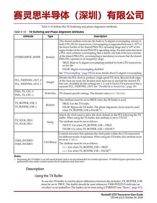
Table 6-10 defines the TX buffering and phase-alignment attributes.DescriptionUsing the TX BufferTo use the TX buffer to resolve phase differences between the domains, TX_BUFFER_USEmust be set to TRUE. The buffer should be reset whenever TXBUFSTATUS indicates anoverflow or an underflow. The buffer can be reset using GTXRESET (see “Reset,” page 101)Table 6-10:TX Buffering and Phase-Alignment Attributes AttributeType DescriptionOVERSAMPLE_MODE Boolean This shared attribute activates the built-in 5x digital oversampling circuits inboth GTX_DUAL transceivers. Oversampling is supported between 1/10th ofthe lower border of the shared PMA PLL operating range and 4/10th of theupper border of the shared PMA PLL operating range. For data rates that needa PLL clock without oversampling that is below one-half of the lower borderof the shared PMA PLL, oversampling is mandatory to ensure that the sharedPMA PLL operates in its frequency range.TRUE: Built-in 5x digital oversampling enabled for both GTX transceiverson the tileFALSE: Digital oversampling disabledSee “Oversampling,” page 185 for more details about 5x digital oversampling.PLL_TXDIVSEL_OUT_0PLL_TXDIVSEL_OUT_1Integer Divides the PLL clock to produce a high-speed TX clock. Because both edges of the clock are used, the divided clock must run at one-half the desired TX line rate. Available divider settings are 1, 2, and 4. Each GTX transceiver has a separate PLL_TXDIVSEL_OUT. See “Parallel In to Serial Out,” page 149.PMA_TX_CFG_0PMA_TX_CFG_120-bit Hex TX channel specific settings. The default value is 20'h80082.TX_BUFFER_USE_0TX_BUFFER_USE_1Boolean This attribute must be set to TRUE when the TX buffer is used.TRUE: Use the TX buffer.FALSE: Bypass the TX buffer. The phase-alignment circuit must be usedwhen TX_BUFFER_USE is FALSE.(1)TX_XCLK_SEL0TX_XCLK_SEL1String Selects the clock used to drive the clock domain in the PCS following the TXbuffer. When using the TX buffer, this attribute is set to TXOUT .The attribute must be set as follows:TXOUT: Use when TX_BUFFER_USE = TRUETXUSR: Use when TX_BUFFER_USE = FALSE (1)TXRX_INVERT0TXRX_INVERT13-bit BinaryControls inverters that optimize the clock paths within the GTX transceiverfor different modes of operation. When using the TX buffer, this attribute mustbe set to 3'b011.The attribute must be set as follows:011: Use when TX_BUFFER_USE =TRUE111: Use when TX_BUFFER_USE =FALSE (1)Notes:1.Bypassing the TX buffer is an advanced feature and is not recommended for normal operation. TX buffer bypass operation can be guaranteed only under certain system-level conditions and data rates.TX Out-of-Band/Beacon Signaling TX Out-of-Band/Beacon SignalingOverviewEach GTX transceiver provides support for generating the Out-of-Band (OOB) sequencesdescribed in the Serial ATA (SATA) specification and beaconing described in the PCIExpress specification. See Appendix B, “OOB/Beacon Signaling,” for an overview of OOBsignaling and how it is used in these protocols.GTX_DUAL support for SATA OOB signaling consists of the analog circuitry required toencode the OOB signal state and state machines to format bursts of OOB signals for SATACOM sequences (COMRESET, COMWAKE, and COMINIT). Each GTX transceiver alsosupports SATA auto-negotiation by allowing the timing of the COM sequences to bechanged based on the divider settings used for the TX line rate.GTX_DUAL supports beaconing as described in the PHY Interface for the PCI Express (PIPE)Specification. The format of the beacon sequence is controlled by the FPGA logic.Ports and AttributesTable6-20 describes the ports that control OOB/beacon signaling.Table 6-20:TX OOB/Beacon Signaling PortsPort Direction Domain DescriptionRXSTATUS0[2:0] RXSTATUS1[2:0]Out RXUSRCLK2The decoding of RXSTATUS[2:0] depends on the setting ofRX_STATUS_FMT:•When RX_STATUS_FMT = PCIE:RXSTATUS is not used for PCIe TXELECIDLE•When RX_STATUS_FMT = SATA:RXSTATUS[0]: TXCOMSTART operation completeRXSTATUS[1]: COMWAKE signal receivedRXSTATUS[2]: COMRESET/COMINIT signal receivedTXCOMSTART0 TXCOMSTART1In TXUSRCLK2Initiates the transmission of the COM* sequence selected byTXCOMTYPE (SATA only).TXCOMTYPE0 TXCOMTYPE1In TXUSRCLK2Selects the type of COM signal to send (SATA only):0: COMRESET/COMINIT1: COMWAKETXELECIDLE0 TXELECIDLE1In TXUSRCLK2When in the P2 power state, this signal controls whether anelectrical idle or a beacon indication is driven out onto the TX pair.TXPOWERDOWN0[1:0] TXPOWERDOWN1[1:0]In TXUSRCLK2Powers down the TX lanes. When in PCIe mode, the GTX_DUALtile must be in the P2 power state (TXPOWERDOWN = 11) togenerate beacon signaling. Use TXPOWERDOWN = 00 for SATAOOB signaling.Table 6-21 defines the OOB/beacon signaling attributes.DescriptionThe GTX_DUAL tile supports two signaling modes: one for SATA operations and one for PCI Express operations. The use of these two mechanisms is mutually exclusive.Beacon Signaling for PCI Express OperationsBeacon signaling for PCI Express operations is performed when the GTX_DUAL tile is in the P2 power state. Transmission of a beacon is initiated by the deassertion ofTXELECIDLE, as shown in Figure 6-26. FPGA control logic controls beacon timing by the sequencing of TXELECIDLE.OOB Signaling for SAT A OperationsOOB signaling for SATA operation is initiated through the use of the TXELECIDLE, TXCOMSTART, and TXCOMTYPE ports. When TXELECIDLE is held High, assertion of TXCOMSTART for one TXUSRCLK2 cycle initiates the transmission of a COM sequence. The type of COM sequence generated is controlled by the TXCOMTYPE port as shown in Table 6-20.The number of bursts in the COM sequence is controlled by the COM_BURST_VALattribute. The timing of the COM sequences transmitted is correct as long as the PLL clock (see “Shared PMA PLL,” page 86) is set to 1.5GHz, and PLL_TXDIVSEL_OUT for each channel is set to either 1 (for a 3.0 Gb/s SATA Generation 2 rate) or 2 (for a 1.5 Gb/s SATA Generation 1 rate).Table 6-21:TX OOB/Beacon Signaling Attributes Attribute TypeDescription COM_BURST_VAL_0COM_BURST_VAL_14-bit Binary Number of bursts in a COM sequence.PLL_SATA_0PLL_SATA_1Boolean Tie to FALSE. When FALSE, PLL_SATA allows TXSATA operations to work at the SATA Generation1 (1.5Gb/s) or SATA Generation2 (3Gb/s) rate.PLL_TXDIVSEL_OUT_0PLL_TXDIVSEL_OUT_1IntegerSets the divider for the TX line rate for theindividual GTX transceiver. Can be set to 1, 2, or 4.Figure 6-26:Beacon Generation for PCI Express Operations10.“Configurable Loss-of-Sync State Machine,” page 19711.“Configurable 8B/10B Decoder,” page 20012.“Configurable RX Elastic Buffer and Phase Alignment,” page 20313.“Configurable Clock Correction,” page 21114.“Configurable Channel Bonding (Lane Deskew),” page 21815.“RX Gearbox,” page 23116.“FPGA RX Interface,” page 236RX Termination and EqualizationOverviewThe first stage of the RX datapath in each GTX transceiver is the RX current mode logic(CML)receiver. This block determines the value of the incoming high-speed differentialsignal.At high speeds, error-free data reception requires good signal integrity. The CML receiverincludes circuits to allow the termination of the channel to be optimized for the bestpossible signal integrity.The receiver also features an RX equalization circuit that allows it to compensate for high-frequency losses in the channel, improving the quality of the received signal. This circuitcan be tuned to meet the specific requirements of the physical channel used in the design.RX Termination and EqualizationTable 7-2 describes the attributes and settings regarding termination for both receivers of the GTX_DUAL tile.DescriptionThe GTX_DUAL receivers are connected via differential pad pairs RXN and RXP to the transmission line on the board. The receiver includes four main features for optimizing signal integrity:•Optional Built-in AC Coupling •Configurable Termination Impedance •Configurable Termination Voltage •Optional 4-Mode Active Linear EqualizationTable 7-2:RX Termination and Equalization Attributes Attribute Type DescriptionAC_CAP_DIS_0AC_CAP_DIS_1Boolean Bypasses the built-in AC coupling in the receiver. Use this attribute whenDC coupling is required. The default for this attribute is FALSE for PCIExpress designs. For all other protocols, the default setting is TRUE.TRUE: Built-in AC coupling capacitors are bypassed. DC coupling to the receiver is possible.FALSE: Built-in AC coupling capacitors are enabled.See Chapter 10, “GTX-to-Board Interface,” for details about when it isappropriate to add an additional external AC coupling capacitor based ondata rate or protocol.CM_TRIM_0CM_TRIM_12-bit Binary Adjusts the input common mode levels. These levels are automatically setin the RocketIO™ GTX Transceiver Wizard.RCV_TERM_GND_0RCV_TERM_GND_1Boolean Activates the Ground reference for the receiver termination network. Thedefault for this attribute is TRUE for PCI Express designs. For all otherprotocols, the default setting is FALSE.TRUE: Ground reference for receiver termination activated.FALSE: Ground reference for receiver termination disabled.See Table 7-4, page 165 for valid combinations of RX terminationattributes. Must be set to TRUE for PCI Express designs.RCV_TERM_VTTRX_0RCV_TERM_VTTRX_1BooleanActivates MGTAVTTRX reference for receiver termination network. Thedefault for this attribute is FALSE for PCI Express designs. For all otherprotocols, the default setting is TRUE. Set to FALSE when using ACcoupling.TRUE: MGTAVTTRX reference for receiver termination activated.FALSE: MGTAVTTRX reference for receiver termination disabled.See Table 7-4, page 165 for valid combinations of RX terminationattributes.TERMINATION_IMP_0TERMINATION_IMP_1Integer Selects the termination impedance for the TX driver and RX CML receiver.See Chapter 10, “GTX-to-Board Interface,” for details on calibration of impedance values.Always set to 50 to select 50Ω termination impedance. The RocketIO GTXTransceiver Wizard automatically sets this parameter to 50.。

逻辑函数的粗糙集表达及最小化方法粗糙集理论是Z. Pawlak于1982年提出的,它是一种用来处理不确定性、模糊性和不完备性的一种数学模型。
粗糙集理论的基本思想是,利用一组属性来描述对象,通过这些属性来划分对象之间的相似度和差异度。
在粗糙集理论中,逻辑函数是一种重要的表达形式。
逻辑函数是通过布尔代数的方式来表达逻辑关系的函数形式,例如AND、OR和NOT等。
在粗糙集理论中,逻辑函数通常可以用来表示集合的包含关系或者近似关系。
逻辑函数的表达可以使用联结词来连接属性,例如AND和OR代表交集和并集。
使用逻辑函数可以方便地表示对象之间的相似性和差异性。
例如,对于一些对象a,可以使用逻辑函数来表示与其相似的对象集合,即具有相同属性的对象。
而与其不相似的对象,则可以使用逻辑函数的补运算来表示。
代数化简是一种常见的逻辑函数最小化方法,它通过运用布尔代数的基本定律和规则,对逻辑函数进行逻辑等价变换和化简,以达到最简形式。
代数化简的过程通常包括合并项、消除项和引入项等步骤。
卡诺图是一种图形化的逻辑函数最小化方法,它通过绘制真值表的方式来构造一个二维的格状图,格状图中的每个格子对应一个逻辑函数的项,通过寻找相邻格子之间的距离来合并相似项,从而实现逻辑函数的最小化。
奎因-麦克劳林展开是一种逻辑函数最小化的代数方法,它利用逻辑代数的展开定理,将逻辑函数展开成最简的形式。
展开的过程通常可以通过二项定理和相似项的合并来进行,以达到逻辑函数的最小化。
在实际应用中,根据需求选择合适的逻辑函数表达形式和最小化方法是非常重要的。
不同的逻辑函数表达形式和最小化方法适用于不同的问题和计算环境。
因此,在应用粗糙集理论中,需要根据具体情况选择合适的方法和技术来处理逻辑函数的表达和最小化问题。
综上所述,逻辑函数的粗糙集表达及最小化方法是粗糙集理论中的重要部分,它可以帮助我们处理不确定性、模糊性和不完备性的问题。
逻辑函数的表达使用布尔代数的方式来描述逻辑关系,可以方便地表示对象之间的相似性和差异性。

Taurus SeriesMultimedia PlayersTB8Specifications Doc u ment V ersion:V1.3.2Doc u ment Number:NS120100363Copyright © 2018 Xi’an NovaStar Tech Co., Ltd. All Rights Reserved.No part of this document may be copied, reproduced, extracted or transmitted in any form or by any means without the prior written consent of Xi’an NovaStar Tech Co., Ltd.Trademarkis a trademark of Xi’an NovaStar Tech Co., Ltd.Statementi TB8 SpecificationsTable of ContentsTable of ContentsYou are welcome to use the product of Xi’an NovaStar Tech Co., Ltd. (hereinafter referred to asNovaStar). This document is intended to help you understand and use the product. For accuracy and reliability, NovaStar may make improvements and/or changes to this document at any time and without notice. If you experience any problems in use or have any suggestions, please contact us via contact info given in document. We will do our best to solve any issues, as well as evaluate and implement any suggestions.Table of Contents (ii)1 Overview (1)1.1 Introduction ..................................................................................................................................................11.2 Application (1)2 Features (3)2.1 Synchronization mechanism for multi-screen playing (3)2.2 Powerful Processing Capability (3)2.3 Omnidirectional Control Plan (3)2.4 Synchronous and Asynchronous Dual-Mode (4)2.5 Dual-Wi-Fi Mode ..........................................................................................................................................42.5.1 Wi-Fi AP Mode (5)2.5.2 Wi-Fi Sta Mode (5)2.5.3 Wi-Fi AP+Sta Mode (5)3 Hardware Structure (7)3.1 Appearance (7)3.1.1 Front Panel (7)3.1.2 Rear Panel ................................................................................................................................................83.2 Dimensions (9)4 Software Structure (10)4.1 System Software (10)4.2 Related Configuration Software (10)5 Product Specifications ................................................................................................................ 116 Audio and Video Decoder Specifications (13)6.1 Image (13)6.1.1 Decoder (13)6.1.2 Encoder (13)6.2 Audio (14)6.2.1 Decoder (14)6.2.2 Encoder (14)6.3 Video (15)ii Table of Contents6.3.1 Decoder (15)6.3.2 Encoder ..................................................................................................................................................16iiiTB8 Specifications 1 Overview1 Overview 1.1 IntroductionTaurus series products are NovaStar's second generation of multimedia playersdedicated to small and medium-sized full-color LED displays.TB8 of the Taurus series products (hereinafter referred to as “TB8”) feature followingadvantages, better satisfying users’ requirements:●Loading capacity up to 2,300,000 pixels●Synchronization mechanism for multi-screen playing●Powerful processing capability●Omnidirectional control plan●Synchronous and asynchronous dual-mode●Dual-Wi-Fi mode Note:If the user has a high demand on synchronization, the time synchronization module isrecommended. For details, please consult our technical staff.In addition to solution publishing and screen control via PC, mobile phones and LAN,the omnidirectional control plan also supports remote centralized publishing andmonitoring.1.2 ApplicationTaurus series products can be widely used in LED commercial display field, such asbar screen, chain store screen, advertising machine, mirror screen, retail storescreen, door head screen, on board screen and the screen requiring no PC.Classification of Taurus’ application cases is shown in Table 1-1. Table1 Overviewaurus Series Multimedia PlayersTB8 Specifications2 Features 2.1 Synchronization mechanism for multi-screen playingThe TB8 support switching on/off function of synchronous display.When synchronous display is enabled, the same content can be played on differentdisplays synchronously if the time of different TB8 units are synchronous with oneanother and the same solution is being played.2.2 Powerful Processing CapabilityThe TB8 features powerful hardware processing capability:● 1.5 GHz eight-core processor●Support for H.265 4K high-definition video hardware decoding playback●Support for 1080P video hardware decoding● 2 GB operating memory●8 GB on-board internal storage space with 4 GB available for users2.3 Omnidirectional Control PlanControl Plan Connecting Mode User Terminal Related SoftwareSolution publishing and screen control through mobile phone Wi-Fi Mobile phone andPadViPlex HandyCluster remote solution publishing and screen control Wi-Fi AP+StaWiredMobile phone, Padand PCVNNOXViPlex HandyViPlex ExpressCluster remote monitoring Wi-Fi AP+StaWiredMobile phone, Padand PCNovaiCareViPlex HandyViPlex ExpressCluster control plan is a new internet control plan featuring following advantages:●More efficient: Use the cloud service mode to process services through a uniformplatform. For example, VNNOX is used to edit and publish solutions, andNovaiCare is used to centrally monitor display status.●More reliable: Ensure the reliability based on active and standby disasterrecovery mechanism and data backup mechanism of the server.●More safe: Ensure the system safety through channel encryption, data fingerprintand permission management.●Easier to use: VNNOX and NovaiCare can be accessed through Web. As long asthere is internet, operation can be performed anytime and anywhere.●More effective: This mode is more suitable for the commercial mode ofadvertising industry and digital signage industry, and makes informationspreading more effective.2.4 Synchronous and Asynchronous Dual-ModeThe TB8 supports synchronous and asynchronous dual-mode, allowing moreapplication cases and being user-friendly.When internal video source is applied, the TB8 is in asynchronous mode; whenHDMI-input video source is used, the TB8 is in synchronous mode. Content can bescaled and displayed to fit the screen size automatically in synchronous mode.Users can manually and timely switch between synchronous and asynchronousmodes, as well as set HDMI priority.2.5 Dual-Wi-Fi ModeThe TB8 have permanent Wi-Fi AP and support the Wi-Fi Sta mode, carryingadvantages as shown below:●Completely cover Wi-Fi connection scene. The TB8 can be connected to throughself-carried Wi-Fi AP or the external router.●Completely cover client terminals. Mobile phone, Pad and PC can be used to login TB8 through wireless network.●Require no wiring. Display management can be managed at any time, havingimprovements in efficiency.TB8’s Wi-Fi AP signal strength is related to the transmit distance and environment.Users can change the Wi-Fi antenna as required.2.5.1 Wi-Fi AP ModeUsers connect the Wi-Fi AP of a TB8 to directly access the TB8. The SSID is “AP +the last 8 digits of the SN”, for example, “AP10000033”, and the default passwordis“12345678”.Configure an external router for a TB8 and users can access the TB8 by connectingthe external router. If an external router is configured for multiple TB8 units, a LAN canbe created. Users can access any of the TB8 via the LAN.2.5.2 Wi-Fi Sta Mode2.5.3 Wi-Fi AP+Sta ModeIn Wi-Fi AP+ Sta connection mode, users can either directly access the TB8 or accessinternet through bridging connection. Upon the cluster solution, VNNOX andNovaiCare can realize remote solution publishing and remote monitoring respectivelythrough the Internet.3Hardware Structure3.1 Appearance3.1.1 Front PanelName DescriptionPWR Power status indicatorAlways on: Power input is normal.System status indicator● Flashing once every other 2 seconds: The system is operating normally.● Flashing once every other second: The system is installing the upgrade package.● Flashing once every other 0.5 second: The system isdownloading data from the Internet or copying the upgrade package.● Always on/off: The system is operating abnormally. CLOUDInternet connection status indicator● Always on: The unit is connected to the Internet and the connection status is normal.● Flashing once every other 2 seconds: The unit is connected to VNNOX and the connection status is normal.SYSFigure 3-1 Front panel of the TB8 Note: All product pictures shown in this document are for illustration purpose only. Actual product may vary.Table 3-1 Description of TB8 front panelW i Fi-S TA COM1AUDIO OUT Audio output3.1.2 RearPanelFigure 3-2 Rear panel of the TB8Note: All product pictures shown in this document are for illustration purpose only.Actual product may vary.Table 3-2 Description of TB8 rear panelName DescriptionRESET Factory reset buttonPress and hold the button for 5 seconds to reset the unit tofactory settings.LED OUT Output Ethernet portON/OFF Power switch100-240V~,50/60Hz Power inputUnit: mmaurus Series Multimedia PlayersTB8 Specifications 4 Software Structure4 Software Structure4.1 System Software●Android operating system software●Android terminal application software●FPGA programNote: The third-party applications are not supported.4.2 Related Configuration SoftwareTable 4-1 Related configuration softwareNovaLCTaurus Series Multimedia Players TB8 Specifications5 Product Specifications5Product Specifications8 GB on-board with 4 GBavailable 0°C–50°CListDimensions for usersPacking informationmensions ( H ×W×D )5 Product SpecificationsAntennaaurus Series Multimedia Players TB8 SpecificationsAudio and Video Decoder6.1.2 EncoderType Codec Supported Image SizeMaximum Data RateRemarks JPEGJPEG Baseline96×32 pixels~8176×8176 pixels90Mpixels/Second JFIF 1.02 N/A6Type Codec Supported Image Size Container RemarksJPEGJFIF1.02JPG, JPEGNot SupportNon-interleaved Scan Software support SRGB JPEGSoftware support Adobe RGB JPEGBMP BMP No Restriction BMP N/A GIF GIF No Restriction GIF N/A PNG PNG No Restriction PNG N/A WEBPWEBPNo RestrictionWEBPN/A48 × 48 p ixels~8176 × 8176 pixel sSpecifications6.1 Image6.1.1 Decoder6.2 AudioOGG, OGA8KHZ~48AMR-NB 2HZ~ 48 1H.264.6.3.2 EncoderMOV, 3GPM bps。

1 GSPS Quadrature Digital Upconverter with 18-Bit IQ Data Path and 14-Bit DACAD9957Rev. 0Information furnished by Analog Devices is believed to be accurate and reliable. However , no responsibility is assumed by Analog Devices for its use, nor for any infringements of patents or other rights of third parties that may result from its use. Specifications subject to change without notice. No license is granted by implication or otherwise under any patent or patent rights of Analog Devices. T rademarks and registered trademarks are the property of their respective owners.One Technology Way, P.O. Box 9106, Norwood, MA 02062-9106, U.S.A.Tel: 781.329.4700 Fax: 781.461.3113 ©2007 Analog Devices, Inc. All rights reserved.FEATURES1 GSPS internal clock speed (up to 400 MHz analog output) Integrated 1 GSPS 14-bit DAC250 MHz I/Q data throughput ratePhase noise ≤ −125 dBc/Hz (400 MHz carrier @ 1 kHz offset) Excellent dynamic performance >80 dB narrow-band SFDR 8 programmable profiles for shift keying SIN(x)/(x) correction (inverse sinc filter) Reference clock multiplierInternal oscillator for a single crystal operation Software and hardware controlled power-down Integrated RAMPhase modulation capability Multichip synchronizationEasy interface to Blackfin SPORTInterpolation factors from 4× to 252× Interpolation DAC mode Gain control DACInternal divider allows references up to 2 GHz 1.8 V and 3.3 V power supplies 100-lead TQFP_EP packageAPPLICATIONSHFC data, telephony, and video modems Wireless base station transmissionBroadband communications transmissions Internet telephonyGENERAL DESCRIPTIONThe AD9957 functions as a universal I/Q modulator and agile upconverter for communications systems where cost, size, power consumption, and dynamic performance are critical. The AD9957 integrates a high speed, direct digital synthesizer (DDS), a high performance, high speed, 14-bit digital-to-analog converter (DAC), clock multiplier circuitry, digital filters, and other DSP functions onto a single chip. It provides for baseband upconversion for data transmission in a wired or wireless communications system. The AD9957 is the third offering in a family of quadrature digital upconverters (QDUCs) that includes the AD9857 and AD9856. It offers performance gains in operating speed, power consumption, and spectral performance. Unlike its predecessors, it supports a 16-bit serial input mode for I/Q baseband data. The device can alternatively be programmed to operate either as a single tone, sinusoidal source or as an interpolating DAC. The reference clock input circuitry includes a crystal oscillator, a high speed, divide-by-two input, and a low noise PLL for multiplication of the reference clock frequency.The user interface to the control functions includes a serial port easily configured to interface to the SPORT of the Blackfin® DSP and profile pins to enable fast and easy shift keying of any signal parameter (phase, frequency, and amplitude).FUNCTIONAL BLOCK DIAGRAM06384-001Figure 1.AD9957Rev. 0 | Page 2 of 60TABLE OF CONTENTSFeatures..............................................................................................1 Applications.......................................................................................1 General Description.........................................................................1 Functional Block Diagram..............................................................1 Specifications.....................................................................................4 Electrical Specifications...............................................................4 Absolute Maximum Ratings............................................................7 ESD Caution..................................................................................7 Pin Configuration and Function Descriptions.............................8 Typical Performance Characteristics...........................................11 Modes of Operation.......................................................................15 Overview......................................................................................15 Quadrature Modulation Mode.................................................16 BlackFin Interface (BFI)............................................................17 Interpolating DAC Mode..........................................................18 Single Tone Mode.......................................................................19 Signal Processing............................................................................20 Parallel Data Clock (PDCLK)...................................................20 Transmit Enable Pin (TxEnable)..............................................20 Input Data Assembler................................................................21 Inverse CCI Filter.......................................................................22 Fixed Interpolator (4×)..............................................................22 Programmable Interpolating Filter..........................................23 Quadrature Modulator..............................................................23 DDS Core.....................................................................................24 Inverse Sinc Filter.......................................................................24 Output Scale Factor (OSF)........................................................25 14-Bit DAC..................................................................................25 Auxiliary DAC........................................................................25 RAM Control..................................................................................26 RAM Overview...........................................................................26 RAM Segment Registers (26)RAM State Machine...................................................................26 RAM Trigger (RT) Pin...............................................................26 Load/Retrieve RAM Operation................................................27 RAM Playback Operation.........................................................27 Overview of RAM Playback Modes.........................................28 RAM Ramp-Up Mode...........................................................28 RAM Bidirectional Ramp Mode..........................................29 RAM Continuous Bidirectional Ramp Mode....................31 RAM Continuous Recirculate Mode...................................32 Clock Input (REF_CLK)................................................................33 REFCLK Overview.....................................................................33 Crystal Driven REF_CLK.........................................................33 Direct Driven REF_CLK...........................................................33 Phase-Locked Loop (PLL) Multiplier......................................34 PLL Charge Pump......................................................................35 External PLL Loop Filter Components...................................35 PLL Lock Indication..................................................................35 Additional Features........................................................................36 Output Shift Keying (OSK).......................................................36 Manual OSK............................................................................36 Automatic OSK.......................................................................36 Profiles.........................................................................................37 I/O_UPDATE Pin......................................................................37 Automatic I/O Update...............................................................37 Power-Down Control................................................................38 General-Purpose I/O (GPIO) Port..........................................38 Synchronization of Multiple Devices...........................................39 Serial Programming.......................................................................42 Control Interface—Serial I/O...................................................42 General Serial I/O Operation...................................................42 Instruction Byte..........................................................................42 Instruction Byte Information Bit Map.. (42)AD9957Rev. 0 | Page 3 of 60Serial I/O Port Pin Descriptions...............................................42 SCLK—Serial Clock................................................................42 CS —Chip Select Bar...............................................................42 SDIO—Serial Data Input/Output.........................................42 SDO—Serial Data Out...........................................................42 I/O_RESET—Input/Output Reset........................................42 I/O_UPDATE—Input/Output Update................................43 Serial I/O Timing Diagrams......................................................43 MSB/LSB Transfers (43)Register Map and Bit Descriptions...............................................44 Register Map................................................................................44 Register Bit Descriptions............................................................49 Control Function Register 1 (CFR1)....................................50 Control Function Register 2 (CFR2)....................................51 Control Function Register 3 (CFR3)....................................52 Auxiliary DAC Control Register...........................................52 I/O Update Rate Register.......................................................53 RAM Segment Register 0.......................................................53 RAM Segment Register 1.......................................................53 Amplitude Scale Factor Register (ASF)...............................53 Multichip Sync Register.........................................................54 Profile Registers...........................................................................55 Profile<0:7> Register—Single T one......................................55 Profile<0:7> Register—QDUC.............................................55 RAM Register..........................................................................55 GPIO Config Register............................................................55 GPIO Data Register................................................................56 Outline Dimensions........................................................................57 Ordering Guide (57)REVISION HISTORY5/07—Revision 0: Initial VersionAD9957Rev. 0 | Page 4 of 60SPECIFICATIONSELECTRICAL SPECIFICATIONSAVDD (1.8V) and DVDD (1.8V) = 1.8 V ± 5%, AVDD (3.3V) = 3.3 V ± 5%, DVDD_I/O = 3.3 V ± 5%, T = 25°C, R SET = 10 kΩ, I OUT = 20 mA, external reference clock frequency = 1000 MHz with REFCLK multiplier disabled, unless otherwise noted. Table 1.Parameter Test Conditions/Comments Min Typ Max Unit REF_CLK INPUT CHARACTERISTICS Frequency RangeREFCLK Multiplier Disabled 25 10001MHz Enabled 3.2 60 MHz Maximum REFCLK Input Divider Frequency Full temperature range 1500 1900 MHz Minimum REFCLK Input Divider Frequency Full temperature range 25 35 MHz External Crystal 25 MHz Input Capacitance 3 pF Input Impedance (Differential) 2.8 kΩ Input Impedance (Single-Ended) 1.4 kΩ Duty Cycle REFCLK multiplier disabled 45 55 % REFCLK multiplier enabled 40 60 % REF_CLK Input Level Single-ended 50 1000 mV p-p Differential 100 2000 mV p-p REFCLK MULTIPLIER VCO GAIN CHARACTERISTICS VCO Gain (K V ) @ Center Frequency VCO0 range setting 429 MHz/V VCO1 range setting 500 MHz/V VCO2 range setting 555 MHz/V VCO3 range setting 750 MHz/V VCO4 range setting 789 MHz/V VCO5 range setting 2 850 MHz/V REFCLK_OUT CHARACTERISTICS Maximum Capacitive Load 20 pF Maximum Frequency 25 MHz DAC OUTPUT CHARACTERISTICS Full-Scale Output Current 8.6 20 31.6 mA Gain Error −10 +10 %FS Output Offset 2.3 μA Differential Nonlinearity 0.8 LSB Integral Nonlinearity 1.5 LSB Output Capacitance 5 pF Residual Phase Noise @ 1 kHz Offset, 20 MHz A OUT REFCLK Multiplier Disabled −152 dBc/Hz Enabled @ 20× −140 dBc/Hz Enabled @ 100× −140 dBc/Hz AC Voltage Compliance Range −0.5 +0.5 V SPURIOUS-FREE DYNAMIC RANGE (SFDR SINGLE TONE) f OUT = 20.1 MHz −70 dBc f OUT = 98.6 MHz −69 dBc f OUT = 201.1 MHz −61 dBc f OUT = 397.8 MHz −54 dBcAD9957Rev. 0 | Page 5 of 60Parameter Test Conditions/Comments Min Typ Max Unit NOISE SPECTRAL DENSITY (NSD) Single Tone f OUT = 20.1 MHz −167 dBm/Hz f OUT = 98.6 MHz −162 dBm/Hz f OUT = 201.1 MHz −157 dBm/Hz f OUT = 397.8 MHz −151 dBm/Hz TWO-TONE INTERMODULATION DISTORTION (IMD) I/Q rate = 62.2 MSPS; 16× interpolation f OUT = 25 MHz −82 dBc f OUT = 50 MHz −78 dBc f OUT = 100 MHz −73 dBc MODULATOR CHARACTERISTICS Input Data Error Vector Magnitude 2.5 Msymbols/s, QPSK, 4× oversampled 0.53 % 270.8333 ksymbols/s, GMSK, 32×oversampled0.77 % 2.5 Msymbols/s 256-QAM, 4×oversampled 0.35 % WCDMA − FDD (TM1), 3.84 MHz Bandwidth,5 MHz Channel SpacingAdjacent Channel Leakage Ratio (ACLR) IF = 143.88 MHz −78 dBc Carrier Feedthrough −78 dBc SERIAL PORT TIMING CHARACTERISTICS Maximum SCLK Frequency 70 Mbps Minimum SCLK Pulse Width Low 4 ns High 4 ns Maximum SCLK Rise/Fall Time 2 ns Minimum Data Setup Time to SCLK 5 ns Minimum Data Hold Time to SCLK 0 ns Maximum Data Valid Time in Read Mode 11 ns IO_UPDATE/PS0/PS1/PS2/RT TIMING CHARACTERISTICS Minimum Pulse Width High 1 SYNC_CLKcycleMinimum Setup Time to SYNC_CLK 2 ns Minimum Hold Time to SYNC_CLK 0 ns IQ INPUT TIMING CHARACTERISTICS Maximum PDCLK Frequency 250 MHz Minimum IQ Data Setup Time to PDCLK 2 ns Minimum IQ Data Hold Time to PDCLK 1 ns Minimum TX_ENABLE Setup Time to PDCLK 2 ns Minimum TX_ENABLE Hold Time to PDCLK 1 ns Minimum TX_ENABLE Pulse Width MISCELLANEOUS TIMING CHARACTERISTICSWake-Up Time 31 Fast Recovery Mode 8 SYSCLK cycles Full Sleep Mode 150 μs Minimum Reset Pulse Width High 5 SYSCLK cycles 4DATA LATENCY (PIPELINE DELAY) Data Latency Single Tone Mode Frequency, Phase, Amplitude-to-DAC Output Matched latency enabled 91 SYSCLK cycles Frequency, Phase-to-DAC Output Matched latency disabled 79 SYSCLK cyclesAD9957Rev. 0 | Page 6 of 60Parameter Test Conditions/Comments Min Typ Max Unit CMOS LOGIC INPUTS Voltage Logic 1 2.0 V Logic 0 0.8 V Current Logic 1 90 120 μA Logic 0 38 50 μA Input Capacitance 2 pF CMOS LOGIC OUTPUTS 1 mA load Voltage Logic 1 2.8 V Logic 0 0.4 V POWER SUPPLY CURRENTDVDD_I/O (3.3V) Pin Current Consumption QDUC mode 16 mA DVDD (1.8V) Pin Current Consumption QDUC mode 610 mA AVDD (3.3V) Pin Current Consumption QDUC mode 28 mA AVDD (1.8V) Pin Current Consumption QDUC mode 105 mA POWER CONSUMPTION Single Tone Mode 800 mW Continuous Modulation 8× interpolation 1400 1800 mW Inverse Sinc Filter Power Consumption 150 200 mW Full Sleep Mode 12 28 mW1 The system clock is limited to 750 MHz maximum in BFI mode. 2The gain value for VCO range Setting 5 is measured at 1000 MHz. 3Wake-up time refers to the recovery from analog power-down modes. The longest time required is for the Reference Clock Multiplier PLL to relock to the reference. 4SYSCLK cycle refers to the actual clock frequency used on-chip by the DDS. If the reference clock multiplier is used to multiply the external reference clock frequency, the SYSCLK frequency is the external frequency multiplied by the reference clock multiplication factor. If the reference clock multiplier and divider are not used, the SYSCLK frequency is the same as the external reference clock frequency.AD9957Rev. 0 | Page 7 of 60ABSOLUTE MAXIMUM RATINGSTable 2.Parameter Rating AVDD (1.8 V), DVDD (1.8 V) Supplies 2 V AVDD (3.3 V), DVDD_I/O (3.3 V) Supplies 4 V Digital Input Voltage −0.7 V to +4 V Digital Output Current 5 mA Storage Temperature Range −65°C to +150°C Operating Temperature Range −40°C to +85°C θJA 22°C/W θJC 2.8°C/W Maximum Junction Temperature 150°C Lead Temperature (10 sec Soldering) 300°CStresses above those listed under Absolute Maximum Ratings may cause permanent damage to the device. This is a stress rating only; functional operation of the device at these or any other conditions above those indicated in the operationalsection of this specification is not implied. Exposure to absolute maximum rating conditions for extended periods may affect device reliability.06384-003AVOID OVERDRIVING DIGITAL INPUTS.FORWARD BIASING ESD DIODES MAY COUPLE DIGITAL NOISE ONTO POWERPINS.DIGITAL INPUTSFigure 2. Equivalent Input Circuit06384-055MUST TERMINATE OUTPUTS TO AGND FOR CURRENT FLOW. DO NOT EXCEED THE OUTPUT VOLTAGE COMPLIANCE RATING.DAC OUTPUTSFigure 3. Equivalent Output CircuitESD CAUTIONAD9957Rev. 0 | Page 8 of 60PIN CONFIGURATION AND FUNCTION DESCRIPTIONSD 16D 15D V D D _I /O (3.3V )D G N D D V D D (1.8V )D 14D 13D 12D 11D 10D 9D 8D 7D 6P D C L K /T S C L K T xE N A B L E /F S DG N D D 5/S P O R T I -D A T A D 4/S P O R T Q -D A T A D 3D V D D _I /O (3.3V )D V D D (1.8V )D 2D 1D 0))U T)))SYNC_IN+SYNC_IN–SYNC_SMP_ERR MASTER_RESET DVDD (1.8V)DVDD (1.8V)06384-004NC = NO CONNECTFigure 4. Pin ConfigurationAD9957Rev. 0 | Page 9 of 60Table 3. Pin Function DescriptionsPin No. Mnemonic I/O 1Description1, 24, 61, 72, 86,87, 93, 97 to 100 NC Not Connected. Allow device pin to float. 2 PLL_LOOP_FILTER I PLL-Loop Filter Compensation. See External PLL Loop Filter Components section. 3, 6, 89, 92 AVDD (1.8V) I Analog Core VDD. 1.8 V analog supplies. 74 to 77, 83 AVDD (3.3V) I Analog DAC VDD. 3.3 V analog supplies.17, 23, 30, 47, 57,64DVDD (1.8V) I Digital Core VDD. 1.8 V digital supplies. 11, 15, 21, 28, 45,56, 66DVDD_I/O (3.3V) I Digital Input/Output VDD. 3.3 V digital supplies. 4, 5, 73, 78, 79, 82, 85, 88, 96A G ND IAnalog Ground. 13, 16, 22, 29, 46,58, 62, 63, 65D G ND I Digital Ground. 7 SYNC_IN+ I Synchronization Signal, Digital Input (Rising Edge Active). Synchronization signal fromexternal master to synchronize internal subclocks. See the Synchronization of Multiple Devices section.8 SYNC_IN− I Synchronization Signal, Digital Input (Falling Edge Active). Synchronization signal fromexternal master to synchronize internal subclocks. See the Synchronization of Multiple Devices section.9 SYNC_OUT+ O Synchronization Signal, Digital Output (Rising Edge Active). Synchronization signal frominternal device subclocks to synchronize external slave devices. See the Synchronization of Multiple Devices section.10 SYNC_OUT− O Synchronization Signal, Digital Output (Falling Edge Active). Synchronization signal frominternal device subclocks to synchronize external slave devices. See the Synchronization of Multiple Devices section.12 SYNC_SMP_ERR O Synchronization Sample Error, Digital Output (Active High). A high on this pin indicatesthat the AD9957 did not receive a valid sync signal on SYNC_IN+/SYNC_IN−. See the Synchronization of Multiple Devices section.14 MASTER_RESET I Master Reset, Digital Input (Active High). This pin clears all memory elements and setsregisters to default values.18 EXT_PWR_DWN I External Power-Down, Digital Input (Active High). A high level on this pin initiates thecurrently programmed power-down mode. See the Power-Down section of this document for further details. If unused, tie to ground.19 PLL_LOCK O PLL Lock, Digital Output (Active High). A high on this pin indicates that the clockmultiplier PLL has acquired lock to the reference clock input.20 CCI_OVFL O CCI Overflow Digital Output, Active High. A high on this pin indicates a CCI filter overflow.This pin remains high until the CCI overflow condition is cleared.25 to 27, 31 to 39, 42 to 44, 48 to 50 D<17:0> I Parallel Data Input Bus (Active High). These pins provide the interleaved, 18-bit, digital, I and Q vectors for the modulator to upconvert. 42 SPORT I-DATA I In Blackfin interface mode, this pin serves as the I-data serial input. 43 SPORT Q-DATA I In Blackfin interface mode, this pin serves as the Q-data serial input. 40 PDCLK/TSCLK O Parallel Data Clock, Digital Output (Clock). See the Signal Processing section for details. 41 TxENABLE I Transmit Enable, Digital Input (Active High). See the Signal Processing section for details. 41 FS I FS Input. In Blackfin interface mode, this pin serves as the FS input to receive the RFSoutput signal from the Blackfin.51 RT I RAM Trigger, Digital Input (Active High). This pin provides control for the RAM amplitudescaling function. When this function is engaged, a high sweeps the amplitude from the beginning RAM address to the end. A low sweeps the amplitude from the end RAM address to the beginning. If unused, connect to ground or supply.52 to 54 PROFILE<2:0> I Profile Select Pins, Digital Inputs (Active High). These pins select one of eightphase/frequency profiles for the DDS core (single tone or carrier tone). Changing the state of one of these pins transfers the current contents of all I/O buffers to the corresponding registers. State changes should be set up to the SYNC_CLK pin.55 SYNC_CLK O Output System Clock/4, Digital Output (Clock). The I/O_UPDATE and PROFILE<2:0> pinsshould be set up to the rising edge of this signal.AD99571 I = input, O = output.Rev. 0 | Page 10 of 60AD9957TYPICAL PERFORMANCE CHARACTERISTICS0–20–10–50–40–30–80–70–60–90–100START 0Hz50MHz/DIVSTOP 500MHz06384-048Figure 5. 15.625 kHz Quadrature Tone, Carrier = 102 MHz,CCI = 16, f S = 1 GHz0–20–10–50–40–30–80–70–60–90–10006384-050Figure 6. 15.625 kHz Quadrature Tone, Carrier = 222 MHz,CCI = 16, f S = 1 GHz0–20–10–50–40–30–80–70–60–90–100START 0Hz50MHz/DIVSTOP 500MHz06384-052Figure 7. 15.625 kHz Quadrature Tone, Carrier = 372 MHz,CCI = 16, f S = 1 GHz 0–20–10–50–40–30–80–70–60–90–100CENTER 102MHz 5kHz/DIV SPAN 50kHz06384-049Figure 8. Narrow-Band View of Figure 5 (with Carrier and Lower Sideband Surpression)0–20–10–50–40–30–80–70–60–90–10006384-051Figure 9. Narrow-Band View of Figure 6 (with Carrier And Lower Sideband Surpression)0–20–10–50–40–30–80–70–60–90–10006384-053Figure 10. Narrow-Band View of Figure 7 (with Carrier and Lower Sideband Surpression)AD99570–20–10–50–40–30–80–70–60–90–100START 0Hz50MHz/DIVSTOP 500MHz06384-044Figure 11. QPSK, 7.8125 Msymbols/s, 4x Oversampled Raised Cosine,α = 0.25, CCI = 8, Carrier = 102 MHz, f S = 1 GHz0–20–10–50–40–30–80–70–60–90–100START 0MHz50MHz/DIVSTOP 500MHz06384-045Figure 12. QPSK, 7.8125 Msymbols/s, 4x Oversampled Raised Cosine,α = 0.25, CCI = 8, Carrier = 222 MHz, f S = 1 GHz0–20–10–50–40–30–80–70–60–90–100START 0Hz50MHz/DIVSTOP 500MHz06384-046Figure 13. QPSK, 7.8125 Msymbols/s, 4x Oversampled Raised Cosine,α = 0.25, CCI = 8, Carrier = 372 MHz, f S = 1 GHz0–20–10–50–40–30–80–70–60–90–100CENTER 102MHz 2MHz/DIV SPAN 20MHz06384-041Figure 14. Narrow-Band View of Figure 110–20–10–50–40–30–80–70–60–90–100CENTER 222MHz2MHz/DIVSPAN 20MHz06384-042Figure 15. Narrow-Band View of Figure 120–20–10–50–40–30–80–70–60–90–100CENTER 372MHz 2MHz/DIV SPAN 20MHz06384-043Figure 16. Narrow-Band View of Figure 13AD9957–50–55–60–65–75–7006384-058S F D R (d B c )FREQUENCY OUT (MHz)050100150200250300350400Figure 17. Wideband SFDR vs. Output Frequency in Single Tone Mode, PLLwith REFCLK = 15.625 MHz × 6406384-059S F D R (d B c )FREQUENCY OUT (MHz)–75–70–65–60–55–45–50Figure 18. SFDR vs. Output Frequency vs. Supply (±5%) in Single Tone Mode40045030025035020015010050006384-060S F D R (d B c )FREQUENCY OUT (MHz)–75–70–65–60–55–50Figure 19. SFDR vs. Temperature in Single Tone Mode–90–100–120–110–140–150–130–170–16006384-061M A G N I T U D E (d B c /H z )FREQUENCY OFFSET (Hz)Figure 20. Residual Phase Noise, System Clock = 1 GHz–90–100–110–120–130–140–150–16006384-054M A G N I T U D E (d B c / H z )FREQUENCY OFFSET (Hz)Figure 21. Residual Phase Noise Using the REFCLK Multiplier, REFCLK = 50 MHz with 20x Multiplication, System Clock = 1 GHz12002004006008001000006384-062P O W E R D I S S I P A T I O N (m W )SYSTEM CLOCK FREQUENCY (MHz)Figure 22. Power Dissipation vs. System Clock (PLL Disabled)AD9957120020040060080010000100200300400500600700800900100006384-063P O W E R D I S S I P A T I O N (m W )SYSTEM CLOCK FREQUENCY (MHz)06384-064–110–100–90–80–70–60–50–40–30–20CENTER 143.86MHzSPAN 25.5MHz2.55MHz/DIVTx CHANNELBANDWIDTH: 3.84MHz ADJACENT CHANNEL BANDWIDTH: 3.84MHzSPACING: 3MHz ADJACENT CHANNEL BANDWIDTH: 3.84MHz SPACING: 10MHzPOWER: –11.88dBm LOWER: –78.27dB UPPER: –78.50dB LOWER: –81.42dB UPPER: –81.87dBW-CDMA SGFF FWDFigure 23. Power Dissipation vs. System Clock (PLL Enabled)Figure 24. Typical ACLR for Wideband CDMAAD9957ctral images and retaining the original ion A detailed block diagram of The inverse sinc filter is available in all three modes.MODES OF OPERATIONOVERVIEWThe AD9957 has three basic operating modes• Quadrature modulation (QDUC) mode (default) • Interpolating DAC mode • Single tone modeThe active mode is selected via the operating mode bits in Control Function Register 1 (CFR1). Single tone mode allows the device to operate as a sinusoidal generator with the DDS driving the DAC directly.Interpolating DAC mode bypasses the DDS, allowing the user to deliver baseband data to the device at a sample rate lowerthan that of the DAC. An internal chain of rate interpolation filters the user data, upsample, to the DAC sample rate. Com-bined, the filters provide for programmable rate interpolation while suppressing spe baseband spectrum.QDUC mode employs both the DDS and the rate interpolat filters. In this case, two parallel banks of rate interpolation filters allow baseband processing of in-phase and quadrature (I/Q) signals with the DDS providing the carrier signal to be modulated by the baseband signals. the AD9957 is shown in Figure 25.06384-005PDCLK I/Q INE X T _P W R _DTxENABLES Y N C _S Y N C P L L _L P L L _L O O P _F I L M A S T E R _R E C C I _O P R O I /O _R E S S I /O _U P DFigure 25. Detailed Block DiagramAD9957QUADRATURE MODULATION MODEA block diagram of the AD9957 operating in QDUC mode is shown in Figure 26; grayed items are inactive. The parallel input accepts 18-bit I- and Q-words in time-interleaved fashion. That is, an 18-bit I-word is followed by an 18-bit Q-word, then the next 18-bit I-word, and so on. One 18-bit I-word and one 18-bit Q-word together comprise one internal sample. The data assembler and formatter de-interleave the I- and Q-words so that each sample propagates along the internal data pathway in parallel fashion. Both I and Q data paths are active; the parallel data clock (PDCLK) serves to synchronize the input of I/Q data to the AD9957.The PROFILE and I/O_UPDATE pins are also synchronous to the PDCLK.The DDS core provides a quadrature (sine and cosine) local oscillator signal to the quadrature modulator, where theinterpolated I and Q samples are multiplied by the respective phase of the carrier and summed together, producing aquadrature modulated data stream. This data stream is routed through the inverse sinc filter (optionally), and the output scaling multiplier. Then it is applied to the 14-bit DAC to produce the quadrature modulated analog output signal.06384-006PDCLK I/Q INE X T _P W R _DTxENABLES Y N C _S Y N C P L L _L O P L L _L O O P _F I L T M A S T E R _R E C C I _O P R O F I /O _R E S S I /O _U P DFigure 26. Quadrature Modulation Mode。
build_item_features原理-回复build_item_features是一个常用的函数,用于构建基于项目的特征。
在推荐系统中,项目特征在评估和推荐过程中起着重要的作用。
本文将详细介绍build_item_features的原理,以及该函数的使用方法和效果。
推荐系统是一种通过分析用户行为和项目特征来向用户推荐感兴趣的项目的技术。
在构建推荐系统中,项目特征是描述项目属性的关键信息。
通过提取项目特征,我们可以将项目分为不同的类别,并根据用户的历史行为和偏好进行推荐。
build_item_features是一个函数,可以帮助我们从项目数据中提取特征,并将其转换为适合使用的数据结构。
其原理如下:1. 收集项目数据:首先,我们需要收集项目数据。
项目数据可以是各种类型的信息,如项目的名称、描述、类别、标签等。
收集项目数据的方式可以是手动输入、从数据库中获取或者通过网络爬取。
2. 特征提取:在收集到项目数据之后,我们需要对数据进行处理,提取关键的项目特征。
常用的特征提取方法包括文本处理、图像处理、语音处理等。
例如,对于文本数据,可以使用自然语言处理技术提取关键词、词频等信息作为项目特征。
3. 特征编码:在提取项目特征之后,我们需要将特征转换为计算机可以处理的形式。
一种常用的方法是使用独热编码,通过将特征转换为二进制向量表示。
例如,对于类别特征,可以使用独热编码将每个类别转换为一个二进制向量,其中某个位置上为1表示该项目属于该类别,为0表示不属于。
4. 构建特征矩阵:在进行特征编码之后,我们将得到一组特征向量。
为了方便计算和推荐,我们将这些特征向量组合成一个特征矩阵。
特征矩阵的每一行代表一个项目,每一列代表一个特征。
5. 数据规范化:在构建特征矩阵之后,我们需要对数据进行规范化处理。
规范化可以将数据映射到一定的范围内,以便于计算和比较。
常用的规范化方法包括最小-最大规范化、标准化等。
6. 结果输出:最后,我们将特征矩阵作为输出,可以通过文件、数据库等方式保存下来,以便在后续的评估和推荐过程中使用。
有向图下的多智能体系统事件触发预设时间实用一致性DOI :10.19557/ki.1001-9944.2024.05.005付璐,陈霞,郭晓亚(青岛理工大学信息与控制工程学院,青岛266525)摘要:该文基于事件触发控制,研究了有向图下的多智能体系统的预设时间实用一致性问题。
首先为每个智能体提出了一个基于时变函数的事件触发控制输入,并构造合适的动态触发条件,使得系统可以在完全预设的时间内达到实用一致性。
该文提出了一个基于李雅普诺夫函数的预设时间稳定性充分条件,借助此条件给出了多智能体系统的预设时间实用一致性分析。
此外,该文从理论上严格排除了整个时间区间上的Zeno 行为。
最后,给出数值仿真实例验证了该文结果的正确性和有效性。
关键词:多智能体系统;事件触发控制;预设时间实用一致性中图分类号:TP13文献标识码:A文章编号:1001鄄9944(2024)05鄄0020鄄06Event 鄄triggered Predefined 鄄time Practical Consensus for Multi 鄄agent Systems Under Directed GraphFU Lu ,CHEN Xia ,GUO Xiaoya(School of Information and Control Engineering ,Qingdao University of Technology ,Qingdao 266525,China )Abstract :In this paper ,we study the predefined 鄄time practical consensus problem for multi 鄄agent systems under di 鄄rected graphs based on event 鄄triggered control.An event 鄄triggered control input based on a time 鄄varying function is firstly proposed for each agent ,and a suitable dynamic triggering condition is constructed so that the system can achieve practical consensus at a completely predefined time.A sufficient condition for the predefined 鄄time stability based on the Lyapunov function is proposed in this paper ,with the help of which the analysis of the multi 鄄agent system predefined 鄄time practical consensus is given.In addition ,this paper rigorously excludes Zeno behavior over the whole time interval from theory.Finally ,a numerical simulation example is given to verify the correctness and validity of the results of this paper.Key words :multi 鄄agent system ;event 鄄triggered control ;predefined 鄄time practical consensus收稿日期:2023-12-08;修订日期:2024-04-15基金项目:国家自然科学基金项目(61703225);山东省自然科学基金项目(ZR2022MF297)作者简介:付璐(1998—),女,硕士,研究方向为多智能体系统的事件触发预设时间一致性;陈霞(通信作者)(1986—),女,博士,副教授,研究方向为事件触发控制、多智能体系统的协调控制等。
Tunable Graphene−Silicon Heterojunctions for Ultrasensitive PhotodetectionXiaohong An,*,†Fangze Liu,†Yung Joon Jung,‡and Swastik Kar*,††Department of Physics and‡Mechanical and Industrial Engineering,Northeastern University,Boston,Massachusetts02115,United States*Supporting Informationand scalable broadband(400<λ<900nm)photodetectors,spectroscopic and imaging devices,and further,and are architecturallyequivalent power,specific detectivityanoscale materials,due to their diverse electronic and optical properties,and with a range of architectures,are constantly being explored for an array of low-cost,sensitive,and scalable photodetection technologies.1−4For example,nano-wires of conventional semiconductor materials such as Si,Ge, GaN,GaAs,InP,and so forth provide a versatile platform for photodetection,affording direct structural and functional compatibility with existing photonic and optoelectronic circuitry.1In contrast,low-cost solution-processable quantum dots are highly appealing due to their potentials for large-area andflexible-electronic applications.Their photoconductive response characterizes high quantum gains resulting in ultrahigh responses(∼103A/W)and specific detectivities (∼1013Jones).2Nanoscale junctions of quantum dots with metals have also been reported to have ultrafast responses of the order of GHz.3Similarly,carbon nanotubes,4with their extremely narrow diameters and chirality-dependent band-gaps, can be potentially utilized for spectrally selective photo-detectors of ultrasmall dimensions.In this context,graphene-based photon-sensing and photo-switching devices have recently attracted enormous attention for their ultrafast and broadband response.5−15Although these devices are highly appealing for ultrafast optical communica-tions,they suffer limitations for weak signal detection,imaging, and spectroscopic applications due to their low responsivity values.Within the visible to telecommunications-friendly wavelength range(i.e.,400nm≤λ≤1550nm),using both photovoltaic5,10and photothermoelectric or hot-carrier ef-fects9,11,14along with enhancement techniques including asymmetric metal-contacts,6plasmonic architectures,7,8and microcavity confinements,12,13the photocurrent responsivity (R I=I ph/P)has at best remained limited within1−2×10⁻²A/ W.7,13These low responses have been primarily attributed to the intrinsically low optical absorption(≈2.3%)of graphene16 along with the absence of any gain mechanisms.By using graphene as the carrier collector and multiplier,an effective gain mechanism(with R I>107A/W)was recently reported in graphene/quantum-dot hybrid devices.15Despite their appeal for ultraweak signal detection,the responsivity of these devices above P≈10−13W fall as R I∼1/P,implying a rapid photocurrent saturation above these incident light powers.With considerably large dark currents that render them ineffective as photoswitches(ON/OFF ratio≪1)and large dark-power consumption,they are impractical for many large-scale applications(such as pixels in imaging devices that require large arrays of photodetectors).For many applications,photovoltage(instead of photo-current)measurements are preferred as a sensitive method for photodetection without any Joule-heating associated power consumption.Past works reveal that metal−graphene interfacesReceived:October3,2012Revised:January22,2013Published:January25,2013can generate photovoltages of ∼1V/W,5which can be enhanced to ∼5V/W using plasmonic focusing and appropriate gate voltages.7It appears that the limits of photovoltage response for low dark-current graphene-based devices,especially under extremely weak signals (where the high responsivities are more meaningful),have not been critically investigated.Further,most of the above-mentioned devices used mechanically exfoliated graphene,17which possess high carrier mobility,but are unsuitable for large-scale deployment.For realistic applications,high-performance devices using large-area chemical vapor deposition (CVD)-grown graphene 18without complex enhancement architec-tures 6−8,12,13are highly desirable.However,so far,a simple approach for obtaining tunable high-responsivity graphene-based devices with low dark currents,low-power detection limits,and high operational dynamic ranges,using simple,scalable,and potentially low-cost techniques remains undem-onstrated.We show that planar 2D heterojunctions of CVD-grown graphene and Si in a conventional Schottky-diode-like con figuration can e ffectively address these issues,providing a platform for a variety of optoelectronic devices.In these junctions,the photoexcitation resides in Si,while graphene is the carrier collector.In recent times,a number of works have explored the unique properties of graphene/Si heterojunctions to develop diodes,19solar cells,20,21and the so-called “barristor ”22 a variable-barrier switch.However,so far,these junctions have not been examined for ultrasensitive photo-detection for applications such as weak-signal imaging or spectroscopy.Further,in these junctions,low reverse-biases can very e ffectively manipulate the Fermi-levels of graphene (unlike larger voltages that are required in capacitively coupled gates).The ability to tune the dark Fermi level (Ef (Gr))of graphene and,more importantly,its relative position with respect to the quasi-Fermi level for holes in silicon (E ′f,h (Si),the modi fied Fermi level due to the generation of photoexcited holes in Si)is a key mechanism that enables a high degree of tunability and e fficient capture of photoexcited carriers,resulting in high photocurrent responsivity values whose performances can be dramatically improved by layer-thickening and simple doping approaches.The tunable photocurrent responsivity is an attractive feature for adjustment to variable-brightness imaging applications.At the same time,these junctions also possess exceptionally high photovoltage response,which increases with decreasing incident power,making it highly suitable as weak-signal detectors in the photovoltage mode.In this work,weFigure 1.(a)Schematic and (b)a digital photograph of a monolayer graphene (1LG)/Si heterojunction device,with the polarity in part (a)shown for forward bias.(c)Thermal equilibrium energy band diagram of the heterojunction in darkness,with the band pro file of n-Si pinned to the charge neutrality levelofitsown surface states (see text).The dark Fermi level of graphene E f (Gr)is also shown.(d)Current −voltage (I −V )curves ofdevice A (area =25mm 2)under darkness and weak illumination (P =1.23μW,λ=488nm)showing a conventional photodiode-like behavior.(e)Deviation of the I −V curves from a conventional photodiode response as the incident light power is increased up to P =6.5mW.The expected ideal photodiode behavior at P =6.5mW is plotted with a red dashed line.(f)Schematic showing the application of a forward bias (V fbias )that lowers E f (Gr)and reduces the number of accessible states for the injection of photoexcited holes from Si,resulting in the strongly suppressed photocurrent in forward bias seen in part e.The red surface on the Dirac cone of graphene denotes the holes injected from Si and is a measure of the maximum photocurrent when the quasi Fermi level of graphene,E ′f (Gr),aligns with the quasi Fermi level for holes in Si,E ′f,h (Si).(g)Application of a reversebias (V r bias )raises E f (Gr)and opens up a large number of accessible states that can be occupied by photoexcited holes injected from Si under illumination.This results in the unsuppressed large photocurrents under reverse bias as seen in part e.The external bias controls the position of the Fermi level and hence the number of photoexcited carriers that can inject from Si (i.e.,the photocurrent).critically investigate the various important parameters of such applications,such as responsivity,detection limit,switching speed,ON/OFF ratio,spectral bandwidth,contrast sensitivity,and dynamic range in monolayer and few-layered graphene/Si heterojunctions,operating both in photocurrent and photo-voltage modes.The photoresponse behaviors were first tested in monolayer graphene (1LG)/Si devices,and their intrinsic parameters were found to be largely independent of size.We present results from the largest (device A)and the smallest (device B)devices with junction areas =25mm 2and 5000μm 2,respectively.We used lightly n-doped Si (ρ=1−10Ωcm),and the details of device fabrication and characterization can be found in the Supporting Information.Figure 1a shows a schematic of a typical monolayer graphene 1LG/Si device,and part b shows a digital photograph of device A.The energy band diagram,showing the Fermi levels of graphene (E f (Gr))and lightly n-doped Si (E f (Si))at thermal equilibrium (in a dark condition)is shown schematically in Figure 1c.From detailed measure-ments of the Schottky barrier heights (as discussed later on),we found that in our devices,E f (Si)was pinned to the charge-neutrality level of its own surface states,with a Schottky barrier height ϕbn ∼0.8V.Figure 1d shows the dark and low-power (P =1.23μW,λ=488nm)current −voltage (I −V )curves in device A,which follow a conventional rectifying and photo-diode-like behavior,respectively.Incident photons generate e −h pairs in Si,and these photoexcited carriers thermalize rapidly to form quasi Fermi levels (separately for holes and electrons near the valence and conduction band edges (VBE and CBE)of Si,respectively).The built-in electric field at the graphene/Si junction causes holes to inject out from Si (from the small energy-band between the VBE and quasi Fermi level for holes in Si)into graphene,which causes the appearance of a quasi Fermi level in graphene,E ′f (Gr).The position of the quasi Fermi level in graphene depends on (a)the position its bias-dependent E f (Gr)and (b)the number of injected holes from Si.At low incident powers,E ′f (Gr)lies between E f (Gr)and E ′f,h (Si),and the photoexcited holes can all find accessible states in graphene to inject into,resulting in the conventional photodiode-like response.Figure 1e shows the I −V curves under increasing incident light powers (up to P =6.5mW).At higher incident powers,there is a signi ficant deviation of the I −V curves from the conventional photodiode-like response,with a strong suppression of photocurrents close to V =0,and a sharp rise and rapid saturation of photocurrents at low reverse biases.This highly tunable photocurrent response is a result of the unique electronic structure of graphene near its Fermi level.Figure 1f schematically represents the situation under a low forward bias,V f bias ,which lowers the Fermi level from its “unbiased ”position.As seen in this figure,the lowering of the Fermi level brings it closer to the quasi Fermi level for holes in Si,greatly diminishing the number of accessible states for the photoexcited carriers to inject into from Si.Hence,under a forward bias,with increasing incident power and rate of hole-injection,E ′f (Gr)lowers and quickly aligns with the quasi Fermi level for holes in Si,E ′f,h (Si)(E ′f (Gr)=E ′f,h (Si),FigureFigure 2.(a)Variation of the voltage responsivity obtained from the open-circuit voltage,V OC ,and as a function of incident power,P ,in device B.At the lowest powers,the voltage responsivity exceeds 107V/W.(b)Variation of the dynamic photovoltage responsivity (or,the contrast sensitivity d VOC /d P )as a function of P in both devices A and B.In device B,the contrast sensitivity exceeds 106V/W at P ≈10nW,and the ∼P −1dependence is identical in both devices.The voltage response to (c)turning ON and (d)turning OFF of incident light in device B,showing exponential rise and fall behaviors with millisecond time scales.In all cases,the incident light wavelength was 488nm.1f).Consequently,only a relatively small photocurrent (denoted by the small red part of the surface of the Dirac cone),limited by the small number of photoexcited holes that can inject into graphene,is possible under forward bias.Increasing the incident light power beyond this point will not allow any more photoexcited holes to inject into graphene since E ′f (Gr)cannot lie below E ′f,h (Si).However,an applied reverse-bias can lift E f (Gr)to higher values,as shown in Figure 1g,opening up a large number of accessible states for the holes to inject into and allowing a complete collection of the injected holes.As a result,the photocurrent,which is signi ficantly suppressed near V ≈0,can completely recover under small reverse biases,as seen in Figure 1e.(These deviations from a conventional photodiode behavior are explained with additional schematics in the Supporting Information document).The photocurrent saturates for a given incident power at higher reverse biases (Figure 1e)when all photoexcited holes can inject into graphene.The photocurrent saturates for a given bias at higher incident powers (see later,Figure 3a)when the quasi-Fermi level in graphene,E ′f (Gr),reaches the quasi-Fermi levelfor holes inSi,E ′f,h (Si).The voltage-induced tunability of therelative positions of the Fermi levels that enables a highphotocurrent responsivity (seelater),along with the low dark-current density (≪1μA/cm 2),results in a tunable photo-current ON/OFF ratio exceeding 104at V =−2V and at a light intensity of 260pW/μm 2making them highly suitable for low-power switches in micrometer-scale optoelectronic circuitry.Figure 2a shows the photovoltage responsivity in device B as a function of incident power.At the lowest incident power,the absolute device responsivity RV (=V OC /P ,VOC is the opencircuit voltage)exceeds 107V/W,which is signi ficantly largerthan that of previously reported graphene-based devices,7Figure 3.(a)The (dark-currentsubtracted)photocurrent (in device A)as a function of incident power for di fferent applied voltages,showing strongvoltage dependence at higher powers.The inset shows the photoresponse of both devices A and B.A device-independent responsivity of 225mA/W was obtained at V =−2V that remains constant over the entire range of powers we were able to test (∼6orders of magnitude).(b)IPCE map of device A,demonstrating the high photon-to-electron conversion e fficiency of ∼57%that can be tuned to remain constant over a large range of incident powers under reverse-bias operation.(c)Variation of IPCE as a function of the incident power at representative operational voltages in device A.The dashed lines are guides to the eye.The IPCE remains nearly unchanged atV =−2V and goes →0at V =0.2V.This small voltagerange (−2to 0.2V)can be used as a switch to turn the photocurrent on and o ffwith a high switching ratio (>104,see text).(d)Transient photocurrent response in device B,showing that the devices were capable of switching within a few milliseconds.In all cases,the incident light wavelength was 488nm.rendering it a highly sensitive device for weak signal detection/ switching/photometry.For applications such as weak-signal imaging,video-recording,or analytical chemistry,sensitivity to extremely small changes in incident power is another important parameter.To quantify this,we define the dynamic photo-voltage responsivity or contrast sensitivity as d V OC/d P.Figure 2b shows the contrast sensitivity in both devices A and B, measured over a broad range of incident powers.Wefind that the contrast sensitivity is remarkably independent of the device areas,exceeding106V/W at low light intensities.In addition, these devices show sharp rise in both the absolute and dynamic responsivity as the incident power decreases,which is a rather convenient feature appropriate for weak-signal detection.For any photodetector,the detection limit is specified by the noise-equivalent-power(NEP),23which is the incident power at which the signal is equal to the RMS dark noise density(S V), measured within a specified bandwidth(commonly1Hz),that is,NEP=S V/R V.To obtain S V,a large sequence of voltage fluctuations(V noise)was measured using a voltmeter set to0.5s integration time(which corresponds to a bandwidth of1Hz),24 while keeping the device in darkness.The RMS noise density was then calculated as S V=(⟨V2noise⟩/1Hz)1/2.For the device B,we obtained S V=1.66×10⁻⁵V/Hz1/2.From the lowest measured power of10nW,R V≈1.8×10⁷V/W,and hence NEP=9.2×10⁻¹³W/Hz1/2(implying that in the photovoltage mode,P∼picoWatt incidences can be detected above the noise level,when integrated over0.5s),and specific detectivity D*=(device area)1/2/NEP=7.69×109Jones(cm Hz1/2/W). Further,at10nW incidence,S V/(d V OC/d P)≈5pW/Hz1/2, indicating that these detectors are capable of distinguishing materials with transmittance,T=0.9995(to compare, transmittance of monolayer graphene is about0.977)within a 0.5s integration time,making it extremely useful for absorption spectroscopy applications of ultradilute or ultrathin materials. We have also examined the transient-response time scale of these detectors,to ascertain how quickly they“switch”when an incident light is turned“on”or“off”.To do this,an optical chopper was placed in front of a laser source,and the photovoltage was recorded as a function of time using an oscilloscope triggered by the same chopper.Figure2c and d show the photovoltage rise and fall response times obtained using a50ms timed optical chopper(which took about∼1.7 ms to completely chop the beam).In both cases,the response could befitted to an exponential function as shown,with time scales of a few milliseconds(with the zero on the time axis corresponding to the point of opening and closing of the chopper).When tested at higher chopping speeds no change was found in the time-scale of the transient response,indicating that the response-time of a few milliseconds was intrinsic to the devices.We also note that the oscilloscope used had an input-impedance rated at1MΩin parallel with a20pF capacitance. The effective time constant of the oscilloscope,RC,=20×10−6seconds,is∼3orders of magnitude smaller than the rise/ fall time of the devices tested and hence did not affect detector transient response in any significant way.In addition,the long-term response to a periodically switching light was found to be extremely stable,with a variation of the OFF and ON state photovoltages well within±2.5%and±5%,respectively,over 1000switching cycles,and with absolutely no sign of drift or aging effects even after10days(see SI).The stable,millisecond level response is quite appealing for applications such as high-speed photography,videography,and rapid optical analysis of chemical reactions that require tens of milliseconds of response time.We now turn to the photocurrent response.Figure3a shows the photocurrent I ph as a function of incident powers for various biases in device A.In the inset,the response for V=−2 V has been plotted for both devices.Wefind that the response not only remains independent of device size but scales in an absolutely linear manner over six decades of incident power. The photocurrent responsivity of∼225mA/W is1−2orders-of-magnitude higher than those of previously reported graphene-based photodetectors5−14and a variety of normal-incidence(i.e.,not waveguide coupled)Ge/Si photodetec-tors,25making it an extremely sensitive linear photodetector and photometer with a large dynamic range.The responsivity can be almost doubled atλ=850nm,as we show later.Also, the presented power range is only limited by our instrumental capabilities,and with higher reverse-biases,the linear response can potentially extend much beyond the experimentally tested range.The range-independent photocurrent responsivity and the d V OC/d P∼1/P dependence suggests that the underlying mechanism in our devices is photovoltaic5−8,10and not hot-carrier-induced or photothermoelectric.9,11,14Figure3b is a3D incident photon conversion efficiency(IPCE(V,P)=(I ph(V,P)/ P)×(hc/eλ))map of device A.By applying a low reverse bias, the device can operate with an IPCE max∼57%over four orders-of-magnitude incident power.As shown in Figure3c,by applying different biases,it is also possible to almost completely tune the IPCE between0<IPCE<IPCE max,which is extremely useful for brightness adjustment in imaging devices. Figure3d shows the typical rise and fall times in response to a chopper.In this case,the responses could not befitted to exponential functions.Nevertheless,it is clear that even in the case of photocurrent detection,the response is rapid enough (within a few milliseconds)for many imaging and analytical applications.The dark noise power spectral density(obtained in a manner similar to the one described earlier for S V)was approximately S I=11pA/Hz1/2.For the undoped1LG/Si device at488nm,this gave a NEP=S I/R I=50pW/Hz1/2, which corresponds to a specific detectivity of1.4×108Jones (cm Hz1/2/W),making it quite a sensitive photodetector even in the photocurrent mode.Moreover,the sensitive behavior of these detectors remain intact over the entire visible range of incident wavelengths,as seen from the spectral dependence of NEP and D*in Figure4,which is an important criterion for broadband imaging applications.The photocurrent responsivity and hence conversion efficiencies could be further improved by increasing the graphene layer-thickness,and yer-thickening pro-vides more states for the holes to inject into,and was achieved by multiple stacking of monolayer sheets of graphene.Doping the graphene sheets can be expected to increase their sheet conductance,and has been utilized in the past to enhance the performance of graphene/Si Solar cells.21In our devices,p-type doping of the graphene sheets was obtained by drop-casting1-pyrenecarboxylic acid(PCA),on the graphene sheets.In the past,we had reported how theπ-stacking interaction between the pyrene part of PCA and graphene can lead to a stable but noncovalent attachment of these molecules to graphene and had performed extensive structural,electronic,optical,and electrochemical characterizations of PCA-functionalized gra-phene.26−28In particular,we have found that attachment of PCA does not seem to have a very significant effect on the thickness of graphene layers26but increases the surfaceroughness of graphene by about 0.2nm (see SI).In addition,Raman spectra of PCA-doped graphene shows an increase in the D-band (see SI)that is most likely due to the presence of large number of edges in the graphene-like crystalline structure of pyrene.Figure 5a shows the resulting p-type doping e ffect of PCA on a separately prepared 3-terminal 1LG transistor.The drain current minimum of pristine graphene devices is at a positive voltage,indicating that the “pristine ”graphene is already p-doped,either due to environment 29or contaminant 30e ffects.The application of PCA shifts the drain current minimum to higher gate voltage values,indicating an additional p-doping e ffect.Figure 5b and c compares the spectral dependence of IPCE and photocurrent responsivity in a three-layer graphene (3LG)/Si device (with and without doping)vis-a -vis the 1LG/Si device A,all of which had the same junction area.The IPCE of 3-layer graphene (3LG)/Si device improves over that of the 1LG/Si device,remaining at ∼60%over a larger window of visible wavelengths.The corresponding responsivity grows to higher values (up to ∼0.4A/W at λ=885nm)in the 3LG/Si device,providing a greater operational bandwidth compared to the 1LG/Si device.After PCA doping,the IPCE and responsivity values increase further over a large window of wavelengths,with maximum IPCE ≈65%between 550and 800nm;and R I ≈435mA/W for 850nm <λ<900nm,making it highly appealing for on-chip applications that could bene fit from the use of energy-e fficient 850nm VCSELs.31We note that,as in the case of the 1LG/Si device,these improved responsivity/IPCE values could be seamlessly extended to high-power applications using low reverse biases (not shown).Finally,we discuss the nature of the interface in these junctions.We have performed extensive measurements of the Schottky barrier height of these junctions,using graphene,doped graphene,and even control devices of Ti/Au with Si (to obtain the “metallic ”side of the junction with a range of work-function values).Since p-doping lowers the Fermi level ofgraphene with respect to its Dirac point,one expects a largerSchottky barrier height,32−35for the p-doped graphene samples.Surprisingly,we found that the Schottky barrier ϕbn =0.79±0.05eV was nearly independent of the “metal ”being used,a fact that can be traced to the nature of the graphene/Si junction.In an ideal Si Schottky junction,the interfaces between the metal and Si is expected to be atomically clean to prevent the formation of any surface states on Si,resulting in the formation of an “unpinned ”Schottky barrier junction,36whose barrier height ϕbn (=ϕm −χSi )is dependent on the work-function of themetal,ϕm .In thermal equilibrium,the Fermi levels on both sides of the junction get aligned,and under illumination,behaves as conventional photodiodes with a reverse-bias independent photocurrent.In contrast,we believe that in our devices,the inadvertent formation of natural oxide on the Si surface,allows the energy bands in Si to naturally “pin ”itself to its own surface states.This results in a Schottky barrier which is still rectifying but with a barrier-heightwhich is pinned to its Bardeen limit of ϕbn ∼0.8eV,36independent of the work function of the metal.With the Fermi level of Si pinned to its own charge-neutrality level,the thermal equilibrium position of the Fermi level of graphene at zero bias is determined by its own intrinsic doping level.UV-emission spectroscopy 37has shown that CVD grown graphene can have work functions as high as 5.2eV (due to substrate-induced e ffects),implyingthat Figure 4.Spectral dependence of the noise-equivalent-power (NEP)and speci fic detectivity (D *)of device B in the photocurrent mode.The minimum NEP and the maximum D *were found to be 33pW/Hz 1/2and 2.1×10⁸Jones,respectively,at λ=730nm.Figure 5.(a)Variation of drain −current as a function of gate voltage in a monolayer graphene 3-terminal transistor without and with PCA doping.The shift of the minima toward higher gate voltages is indicative of p-type doping due to PCA.(b)Spectral dependence of IPCE (200nm <λ<1100nm)of deviceA (1LG/Si)versus a 3LG/Sidevicebeforeand after dopingwith PCA.(c)Spectral responsivity for the same devices within thesame wavelength window.The improved bandwidth and e fficiency/response is clearly visible with increased layer thickness and doping.The doped 3LG/Si device has the best IPCE exceeding 60%over a broad range and with a maximum IPCE exceeding 65%.The responsivity peaks at ≈435mA/W for 850nm <λ<900nm.the Fermi level can lie very close to the valence band edge of Si, effectively preventing the injection of photoinduced carriers into graphene under zero applied bias.We believe that this causes the suppressed photocurrent at zero-bias seen in our devices.This turns out to be an attractive feature,as it allows for an additional tunability of the photocurrent that results in the voltage-controllable responsivity discussed before. Hence,graphene/Si heterojunctions can be used for a variety of tunable optoelectronic devices with high responsivities over a broad spectral bandwidth in the visible region.Their high responses and low dark-currents render them with a high switching ratio and low dark-power consumption.The picoWatt-level detection capability in both photovoltage and photocurrent modes along with linear operation demonstrated up to milliwatts of incident powers reflects a significantly large dynamic operational range.This,in addition to their milli-second-responses makes them versatile and highly sensitive photodetectors for a variety of imaging,metrology,and analytical applications over a broad range of input powers. The voltage-tunability allows brightness control for variable light conditions and enables linear operation over a large dynamic range.The responsivity peaking at850nm is ideal for coupling with VCSELs operating at these wavelengths31for low-power integrated optoelectronic circuitry.Built using simple,low-cost,and scalable methods,additional improve-ments of CVD-graphene quality,38integration with as wave-guides,25and plasmonic7,8or microcavity11,12enhancements could lead to greater performances.Moreover,graphene junctions with other semiconductors such as Ge,GaAs,and so forth can provide furtherflexibility for controlling the peak-responsivity,spectral bandwidth,and high-speed operations.■ASSOCIATED CONTENT*Supporting InformationExperimental details about the synthesis of graphene and device fabrication;characterization of graphene samples;responsivity measurement as function of power and wavelength;time-dependent switching response;AFM and Raman character-ization of PCA-doped graphene.This material is available freeof charge via the Internet at .■AUTHOR INFORMATIONCorresponding Author*E-mail:x.an@(X.A.);s.kar@(S.K.).NotesThe authors declare no competingfinancial interest.■ACKNOWLEDGMENTSWe acknowledge thefinancial support provided by the Northeastern University start-up and internal seed grants provided to S.K.and Y.J.J.and partial support from an NSFaward:ECCS-1202376.■REFERENCES(1)Yan,R.;Gargas,D.;Yang,P.Nanowire Photonics.Nat.Photonics 2009,3,569−576.(2)Konstantatos,G.;Howard,I.;Fischer,A.;Hoogland,S.;Clifford, J.;Klem,E.;Levina,L.;Sargent,E.H.Ultrasensitive solution-cast quantum dot photodetectors.Nature2006,442,180−183.(3)Prins,F.;Buscema,M.;Seldenthuis,J.S.;Etaki,S.;Buchs,G.; Barkelid,M.;Zwiller,V.;Gao,Y.;Houtepen,A.J.;Siebbeles,L.D.A.; Zant,H.S.J.Fast and Efficient Photodetection in Nanoscale Quantum-Dot Junctions.Nano Lett.2012,12,5740−5743.(4)Avouris,P.;Freitag,M.;Perebeinos,V.Carbon-nanotubePhotonics and Optoelectronics.Nat.Photonics2008,2,341−350. (5)Xia,F.N.;Mueller,T.;Lin,Y.M.;Garcia,A.V.;Avouris,P.Ultrafast graphene photodetector.Nat.Nanotechnol.2009,4,839−843.(6)Muller,T.;Xia,F.N.;Avouris,P.Graphene Photodetectors for high-speed optical communications.Nat.Photon.2010,4,297−301.(7)Echtermeyer,T.J.;Britnell,L.;Jasnos,P.K.;Lombardo,A.; Gorbachev,R.V.;Grigorenko,A.N.;Geim,A.K.;Ferrari,A.C.; Novoselov,K.S.Strong Plasmonic enhancement of photovoltage in mun.2011,2,458.(8)Liu,Y.;Cheng,C.;Liao,L.;Zhou,H.;Bai,J.;Liu,G.;Liu,L.; Huang,Y.;Duan,X.Plasmon resonance enhanced multicolour photodetection by mun.2011,2,579.(9)Gabor,N.M.;Song,J.C.W.;Ma,Q.;Nair,N.L.;Taychatanapat,T.;Watanabe,K.;Taniguchi,T.;Levitov,L.S.;Jarillo-Herrero,P.Hot carrier−assisted intrinsic photoresponse in graphene.Science2011, 334,648−652.(10)Park,J.;Ahn,Y.H.;Ruiz-vargas,C.Imaging of PhotocurrentGeneration and Collection in Single-Layer Graphene.Nano Lett.2009, 9,1742−1746.(11)Sun,D.;Aivazian,G.;Jones,A.M.;Ross,J.S.;Yao,W.;Cobden,D.;Xu,X. D.Ultrafast hot-carrier-dominated photocurrent in graphene.Nat.Nanotechnol.2012,7,114−118.(12)Engel,M.;Steiner,M.;Lombardo,A.;Ferrari,A.C.;Lo h neysen,H.v.;Avouris,P.;Krupke,R.Light−matter interaction in amicrocavity-controlled graphene mun.2012,3, 906.(13)Furchi,M.;Urich,A.;Pospischil,A.;Lilley,G.;Unterrainer,K.; Detz,H.;Klang,P.;Andrews,A.M.;Schrenk,W.;Strasser,G.; Mueller,T.Microcavity-Integrated Graphene Photodetector.Nano Lett.2012,12,2773−2777.(14)Xu,X.;Gabor,N.M.;Alden,J.S.;Zande,A.M.;McEuen,P.L. Photo-Thermoelectric Effect at a Graphene Interface Junction.Nano Lett2010,10,562−566.(15)Konstantatos,G.;Badioli,M.;Gaudreau,L.;Osmond,J.;Bernechea,M.;Arquer,F.P.G.;Gatti,F.;Koppens,F.H.L.Hybrid graphene−quantum dot phototransistors with ultrahigh gain.Nat. Nanotechnol.2012,7,363−368.(16)Nair,R.N.;Blake,P.;Grigorenko,A.N.;Novoselov,K.S.;Booth,T.J.;Stauber,T.;Peres,N.M.R.;Geim,A.K.Fine structure constant defines visual transparency of graphene.Science2008,320, 1308.(17)Novoselov,K.S.;Geim,A.K.;Morozov,S.V.;Jiang,D.;Zhang,Y.;Dubonus,S.V.;Grigorieva,I.V.;Firsov,A.A.Electric Field Effect in Atomically Thin Carbon Films.Science2004,306,666−669. (18)Li,X.;Cai,W.;An,J.;Kim,S.;Nah,J.;Yang,D.;Piner,R.; Velamakanni,A.;Jung,I.;Tutuc,E.;Banerjee,S.K.;Colombo,L.; Ruoff,rge-Area Synthesis of High-Quality and Uniform Graphene Films on Copper Foils.Science2009,324,1312−1314. (19)Chen,C.;Aykol,M.;Chang,C.;Levi,A.F.J.;Cronin,S.B. Graphene-Silicon Schottky Diodes.Nano Lett2011,11,1863−1867.(20)Li,X.M.;Zhu,H.;Wang,K.;Cao,A.;Wei,J.;Li,C.;Jia,Y.;Li,Z.;Li,X.;Wu,D.Graphene-on-silicon Schottky Junction Solar Cells. Adv.Mater.2010,22,2743−2748.(21)Miao,X.;Tongay,S.;Petterson,M.K.;Berke,K.;Rinzler,A.G.; Appleton,B.R.;Hebard,A.F.High Efficiency Graphene Solar Cells by Chemical doping.Nano Lett.2012,12,2745−2750.(22)Yang,H.;Heo,J.;Park,S.;Song,H.J.;Seo,D.H.;Byun,K.E.;Kim,P.;Yoo,I.;Chung,H.J.;Kim,K.Graphene Barristor,a Triode Device with a Gate-Controlled Schottky Barrier.Science2012,336, 1140−1143.(23)Richards,P.L.Bolometers for infrared and millimeter waves.J.Appl.Phys.1994,76,1−24.(24)Shannon,munication in the Presence of Noise.Proc.IEEE1998,86,447−457.(25)Michel,J.;Liu,J.;Kimerling,L.C.High-performance Ge-on-Siphotodetectors.Nat.Photonics2010,4,527−534.。
[1]R.H.Abraham and C.D.S haw,Dynamics—The Geometry of Behavior,Reading MA:Addison-Wesley,1992.[2]K.T.Alligood,T.D.Sauer and J.A.Yorke,Chaos:An Introductionto Dynamical Systems,New York:Springer-Verlag,1996.[3]J.Argyris,G.Faust and M.Haase,An Exploration of Chaos,Amster-dam:Elsevier Science BV,1994.[4] D.K.Arrowsmith and C.M.Place,An Introduction to DynamicalSystems,Cambridge:Cambridge University Press,1990.[5] A.El Aroudi,Hopf bifurcation and chaos from torus breakdown in apwm voltage-controlled dc/dc boost converters,IEEE Transactions on Circuits and Systems Part I,vol.46,no.11,pp.1374–1382,1999.[6]S.Banerjee,Coexisting attractors,chaotic saddles,and fractal basins ina power electronic circuit,IEEE Transactions on Circuits and SystemsPart I,vol.44,no.9,pp.847–849,1997.[7]S.Banerjee and K.Chakrabarty,Nonlinear modeling and bifurcationsin the boost converter,IEEE Transactions on Power Electronics,vol.13, no.2,pp.252–260,1998.[8]S.Banerjee,M.S.Karthik,G.H.Yuan and J.A.Yorke,Bifurcationsin one-dimensional piecewise smooth maps—theory and applications in switching circuits,IEEE Transactions on Circuits and Systems Part I, vol.47,no.3,pp.389–394,2000.[9]S.Banerjee,P.Ranjan and C.Grebogi,Bifurcation in two-dimensionalpiecewise smooth maps—theory and applications in switching cir-cuits,IEEE Transactions on Circuits and Systems Part I,vol.47,no.5, pp.633–643,2000.[10]S.Banerjee,E.Ott,J.A.Yorke and G.H.Yuan,Anomalous bifur-cations in dc-dc converters:borderline collisions in piecewise smooth maps,IEEE Power Electronics Specialists Conference Record,pp.1337–1344,1997.[11]S.Banerjee and G.Verghese(Editors),Nonlinear Phenomena in PowerElectronics:Attractors,Bifurcations,Chaos,and Nonlinear Control, New York:IEEE Press,2001.[12] A.L.Baranovski,A.M¨o gel,W.Schwarz and O.Woywode,Statisticalanalysis of a dc-dc converter,Proceedings of International Workshop on Nonlinear Dynamics of Electronic Systems,pp.15–18,1999.[13]R.M.Bass,B.S.Heck and R.A.Khan,Average modeling of current-controlled converters:instability prediction,International Journal of Electronics,vol.77,no.5,pp.613–628,1994.[14]M.di Bernardo,C.J.Budd and A.R.Champneys,Grazing and border-collision in piecewise-smooth systems:a unified analytical framework, Physics Review Letters,vol.86,no.12,pp.2553–2556,2000.[15]M.di Bernardo,C.J.Budd and A.R.Champneys,Corner collisionimplies border collision,Physica D,vol.154,pp.171–194,2001. [16]M.di Bernardo,E.Fossas,G.Olivar and F.Vasca,Secondary bifur-cations and high-periodic orbits in voltage controlled buck converter, International Journal of Bifurcation and Chaos,vol.12,No.7,pp.2755–2771,1997.[17]M.di Bernardo,F.Garofalo,L.Glielmo and F.Vasca,Quasi-periodicbehaviours in dc-dc converters,IEEE Power Electronics Specialists Con-ference Record,pp.1376–1381,1996.[18]M.di Bernardo,L.Glielmo,F.Garofalo and F.Vasca,Switching,bifur-cations and chaos in dc/dc converters,IEEE Transactions on Circuits and Systems Part I,vol.45,no.2,pp.133–141,1998.[19]M.di Bernardo and F.Vasca,Discrete-time maps for the analysis of bi-furcations and chaos in dc/dc converters,IEEE Transactions on Circuits and Systems Part I,vol.47,no.2,pp.130–143,2000.[20] B.K.Bose,Modern Power Electronics:Evolution,Technology and Ap-plications,New York:IEEE Press,1992.[21]R.W.Brockett and J.R.Wood,Understanding power converter chaoticbehavior in protective and abnormal modes,Proceedings of Powercon II,1984.[22] A.Capel,G.Ferrante,D.O’Sullivan and A.Weinberg,Application ofthe injected-current control model for the dynamic analysis of switching regulators with a new concept of LC3modulator,IEEE Power Electron-ics Specialists Conference Record,pp.135–147,1978.[23]W.C.Y.Chan and C.K.Tse,A universal bifurcation path conjec-tured from current-programmed switching converters,Proceedings of International Symposium on Nonlinear Theory and Its Applications, (NOLTA’96),Japan,pp.121–124,1996.[24]W.C.Y.Chan and C.K.Tse,On the form of feedback function thatcan lead to chaos in discontinuous-mode dc/dc converters,IEEE Power Electronics Specialists Conference Record,pp.1317–1322,1997.[25]W. C.Y.Chan and C.K.Tse,Study of bifurcation in current-programmed dc/dc boost converters:from quasiperiodicity to period-doubling,IEEE Transactions on Circuits and Systems Part I,vol.44, no.12,pp.1129–1142,1997.[26]W.C.Y.Chan and C.K.Tse,Bifurcations in current-programmeddc/dc buck switching regulators—conjecturing a universal bifurcation path,International Journal of Circuit Theory and Applications,vol.26, no.2,pp.127–145,1998.[27]K.Chakrabarty,G.Podder and S.Banerjee,Bifurcation behavior ofbuck converter,IEEE Transactions on Power Electronics,vol.11,no.3, pp.439–447,1995.[28]G.Chen(Editor),Controlling Chaos and Bifurcations in EngineeringSystems,Boca Raton:CRC Press,2000.[29]G.Chen and X.Dong,From Chaos to Order:Methodologies,Perspec-tives and Applications,Singapore:World Scientific,1998.[30]G.Chen and T.Ueta(Editors),Chaos in Circuits and Systems,Singa-pore:World Scientific,2002.[31]W.K.Chen(Editor),The Circuits and Filters Handbook,Boca Raton:CRC Press,1995.[32]Y.Chen and A.Y.T.Leung,Bifurcation and Chaos in Engineering,New York:Springer-Verlag,1998.[33]G.C.Chryssis,High-Frequency Switching Power Supplies:Theory andDesign,New York:McGraw Hill,1989.[34]L.O.Chua,M.Hasler,J.Neirynck and P.Verburgh,Dynamics of apiecewise linear resonant circuit,IEEE Transactions on Circuits and Systems Part I,vol.29,no.8,pp.535–547,1982.[35]L.O.Chua,C.W.Wu,A.Huang and G.Q.Zhong,A universal circuitfor studying and generating chaos—Part I:routes to chaos,IEEE Trans-actions on Circuits and Systems Part I,vol.40,no.10,pp.732–744, 1993.[36]L.O.Chua,C.W.Wu,A.Huang and G.Q.Zhong,A universal circuitfor studying and generating chaos—Part II:strange attactors,IEEE Transactions on Circuits and Systems Part I,vol.40,no.10,pp.745–761,1993.[37]S.´Cuk and R.D.Middlebrook,A new optimum topology switching dc-to-dc converter,IEEE Power Electronics Specialists Conference Record, pp.160–179,1977.[38]J.H.B.Deane,Chaos in a current-mode controlled boost converter,IEEE Transactions on Circuits and Systems Part I,vol.39,no.8, pp.680–683,1992.[39]J.H.B.Deane and D.C.Hamill,Instability,subharmonics,and chaosin power electronic circuits,IEEE Transactions on Power Electronics, vol.5,no.3,pp.260–268,1990.[40]J.H.B.Deane and D.C.Hamill,Improvement of power supply EMCby chaos,IEE Electronics Letters,vol.32,p.1045,1996.[41]R.L.Devaney,Introduction to Chaotic Dynamical Systems,New York:Addison-Wesley,1989.[42]L.H.Dixon Jr.,High power factor preregulator for off-line power sup-plies,Unitrode Switching Regulated Power Supply Design Manual,Pa-per12,SEM-700,1990.[43]I.Dobson,Stability of ideal thyristor and diode switching circuits,IEEETransactions on Circuits and Systems Part I,vol.42,no.9,pp.517–529, 1995.[44]P.G.Drazin,Nonlinear Systems,Cambridge UK:Cambridge UniversityPress,1992.[45] C.C.Fang and E.H.Abed,Saddle-node and Neimark bifurcations inpwm converters,in Nonlinear Phenomena in Power Electronics:Attrac-tors,Bifurcations,Chaos and Nonlinear Control,Edited by S.Banerjee and G.Verghese,Section5.4,pp.229–240,New York:IEEE Press, 2001.[46]N.Femia,G.Spagnuolo and V.Tucci,State-space models and orderreduction for dc-dc switching converters in discontinuous mode,IEEE Transactions on Power Electronics,vol.10,no.6,pp.640–650,1995.[47]J.A.Ferreira,P.R.Willcock and S.R.Holm,Sources,paths andtraps of conducted EMI in switch mode circuits,Proceedings of IEEE Industry Applications Conference,pp.1584–1591,1997.[48] E.Fossas and G.Olivar,Study of chaos in the buck converter,IEEETransactions on Circuits and Systems Part I,vol.43,no.1,pp.13–25, 1996.[49] D.S.Garabandic and T.B.Petrovic,Modeling parallel operating PWMDC/DC power supplies,IEEE Transactions on Industrial Electronics, vol.42,no.5,pp.545–550,1995.[50]R.Giral,L.Martinez-Salamero and S.Singer,Interleaved convertersoperation based on CMC,IEEE Transactions on Power Electronics, vol.14,no.4,pp.643–652,1999.[51]J.Gleick,Chaos:Making a New Science,New York:Viking,1987.[52] C.Grebogi,E.Ott and J.A.Yorke,Crisis,sudden changes in chaoticattractors,and transient chaos,Physica D,vol.7D,pp.181–200,1983.[53]J.Guckenheimer and P.Holmes,Nonlinear Oscillations,Dynamical Sys-tems and Bifurcations of Vector Fields,New York:Springer-Verlag, 1983.[54] D.Gulick,Encounters with Chaos,New York:McGraw Hill,1992.[55]J.Hale,Ordinary Differential Equations,New York:Wiley,1969.[56]J.Hale and H.Kocak,Dynamics and Bifurcations,New York:Springer-Verlag,1991.[57]N.Hall(Editor),Exploring Chaos:A Guide to the New Science ofDisorder,New York:Norton,1991.[58] D.C.Hamill,Power electronics:afield rich in nonlinear dynamics,Pro-ceedings of International Specialists’Workshop on Nonlinear Dynamics of Electronic Systems,pp.165–177,1995.[59] D.C.Hamill,S.Banerjee and G.C.Verghese,Chapter1:Introduc-tion,in Nonlinear Phenomena in Power Electronics,S.Banerjee andG.C.Verghese(Eds.),New York:IEEE Press,2001.[60] D.C.Hamill,J.H.B.Deane and D.J.Jefferies,Modeling of chaoticdc/dc converters by iterative nonlinear mappings,IEEE Transactions on Power Electronics,vol.7,no.1,pp.25–36,1992.[61] D.C.Hamill and D.J.Jefferies,Subharmonics and chaos in a controlledswitched-mode power converter,IEEE Transactions on Circuits and Systems Part I,vol.35,no.8,pp.1059–1061,1988.[62]M.Hasler,Electrical circuits with chaotic behavior,Proceedings ofIEEE,vol.75,no.8,pp.1009–1021,August1987.[63] C.Hayashi,Nonlinear Oscillations in Physical Systems,New York:Mc-Graw Hill,1964.[64] C.Hayashi,Y.Ueda and H.Kawakami,Solutions of Duffing’s equationusing mapping concepts,Proceedings of International Conference on Nonlinear Oscillations,Prague,pp.25–40,1968.[65]R.C.Hilborn,Chaos and Nonlinear Dynamics:An Introduction forScientists and Engineers,New York:Oxford University Press,2000. [66] B.Holland,Modelling,analysis and compensation of the current-modeconverter,Proceedings of Powercon11,pp.I-2-1–I-2-6,1984.[67]H.H.C.Iu and C.K.Tse,A study of synchronization in chaotic au-tonomous´Cuk dc/dc converters,IEEE Transactions on Circuits and Systems Part I,vol.47,no.6,pp.913–918,June2000.[68]H.H.C.Iu and C.K.Tse,Bifurcation in parallel-connected boost dc/dcconverters,Proceedings of IEEE International Symposium on Circuits and Systems,pp.II473–II476,2000.[69]H.H.C.Iu and C.K.Tse,Bifurcation behaviour in parallel-connectedbuck converters,IEEE Transactions on Circuits and Systems Part I, vol.48,no.2,pp.233–240,2001.[70]H.H.C.Iu and C.K.Tse,Bifurcation in parallel-connected boostconverters under democratic current sharing,Proceedings of IEEE In-ternational Symposium on Industrial Electronics,pp.2118–2123,2001.[71]H.H.C.Iu,C.K.Tse and i,Effects of interleaving on the bi-furcation behaviour of parallel-connected buck converters,Proceedings of IEEE International Conference on Industrial Technology,Bangkok, Thailand,pp.1072–1077,December2002.[72]H.H.C.Iu,C.K.Tse,V.Pjevalica and i,Analysis of Hopfbifurcation in parallel-connected boost converters via averaged models, Proceedings of IEEE International Symposium on Circuits and Systems, Arizona USA,pp.V-305–308,2002.[73]S.Jalali,I.Dobson,sseter and G.Venkataramanan,Switchingtime bifurcation in a thyristor controlled reactor,IEEE Transactions on Circuits and Systems Part I,vol.43,no.3,pp.209–218,1996.[74]M.M.Jovanovi´c,D.E.Crow and F.Y.Lieu,A novel,low-cost imple-mentation of democratic load-current sharing of paralleled converter modules,IEEE Transactions on Power Electronics,vol.11,no.4, pp.604–611,1996.[75]T.Kapitaniak,Controlling Chaos,London:Academic Press,1996.[76]T.Kapitaniak,Chaos for Engineers:Theory,Applications and Control,Heidelberg:Springer-Verlag,2000.[77]T.Kapitaniak and S.R.Bishop,The Illustrated Dictionary of NonlinearDynamics and Chaos,Chichester:Wiley,1999.[78]J.G.Kassakian,M.F.Schlecht and G.C.Verghese,Principles of PowerElectronics,Reading:Addison-Wesley,1991.[79]H.Kawakami,Theory of Nonlinear Phenomena and Dynamical Sys-tems,Research Institute for Mathematical Sciences,Kyoto University, Japan,No.506,1983.[80]J.H.Kim and J.Stringer(Editors),Applied Chaos,New York:Wiley,1992.[81] A.S.Kislovski,R.Redl and N.O.Sokal,Dynamical Analysis of Switch-ing Mode DC/DC Converters,New York:Van Nostrand Reinhold,1996.[82]T.Kousaka,T.Ueta and H.Kawakami,Bifurcation in switched non-linear dynamical systems,IEEE Transactions on Circuits and Systems Part II,vol.46,no.7,pp.878–885,1999.[83]P.T.Krein,Elements of Power Electronics,New York:Oxford Univer-sity Press,1998.[84]Y.Kuroe and S.Hagashi,Analysis of bifurcation in power electronic in-duction motor drive systems,IEEE Power Electronics Specialists Con-ference Record,pp.923–930,1989.[85]Y.A.Kuznetsov,Elements of Applied Bifurcation Theory,New York:Springer-Verlag,1996.[86]i,C.Grebogi and i,Sudden change in the size of chaoticattractors:how does it occur?Applications of Chaos,pp.411–456,New York:Wiley Interscience,1992.[87]i,Power supplies,in The Power Electronics Handbook:De-vices,Circuits and Applications,Edited by M.H.Rashid,Chapter20, pp.487–506,New York:Academic Press,2001.[88]Y.S.Lee,Computer Aided Analysis and Design of Switch Mode PowerSupplies,New York:Marcel Dekker,1993.[89]Y.H.Lim and D.C.Hamill,Problems of computing Lyapunov expo-nents in power electronics,Proceedings of IEEE International Sympo-sium on Circuits and Systems,pp.297–301,1999.[90] C.S.Lin and C.L.Chen,Single-wire current-share paralleling ofcurrent-mode-controlled DC power supplies,IEEE Transactions on In-dustrial Electronics,vol.47,no.4,pp.780–786,2000.[91]K.H.Liu and F.C.Lee,Topological constraints on basic PWM con-verters,Power Electronics Specialists Conference Record,pp.164–172, 1988.[92] E.N.Lorenz,Deterministic nonperiodicflow,Journal of AtmosphericScience,vol.2,pp.130–141,1963.[93] E.N.Lorenz,The Essence of Chaos,London:Cambridge UniversityPress,1993.[94] A.Magauer and S.Banerjee,Bifurcations and chaos in the toleranceband pwm technique,IEEE Transactions on Circuits and Systems Part I,vol.37,no.3,pp.399–409,1990.[95]J.L.R.Marrero,J.M.Font and G.C.Verghese,Analysis of the chaoticregime for dc-dc converters under current mode control,IEEE Power Electronics Specialists Conference Record,pp.1477–1483,1996.[96]S.K.Mazumder,A.H.Nayfeh and D.Boroyevich,Theoretical andexperimental investigation of the fast-and slow-scale instabilities of a dc/dc converter,IEEE Transactions on Power Electronics,vol.16,no.2, pp.201–216,2001.[97]S.K.Mazumder,A.H.Nayfeh and D.Boroyevich,A nonlinear ap-proach to the analysis of stability and dynamics of standalone and par-allel DC-DC converters,Proceedings of IEEE Applied Power Electronics Conference and Exposition,pp.784–790,2001.[98]R.D.Middlebrook and S.´Cuk,A general unified approach to modelingswitching-converter power stages,IEEE Power Electronics Specialists Conference Record,pp.18–34,1976.[99] D.M.Mitchell,DC-DC Switching Converter Analysis,New York:Mc-Graw Hill,1988.[100]N.Mohan,T.Undeland and W.Robbins,Power Electronics,New York: Wiley,1995.[101] F.C.Moon,Chaotic and Fractal Dynamics,Chichester:Wiley,1992. [102]I.Nagy,Nonlinear phenomena in power electronics,Journal Au-tomatika,vol.42,no.3–4,pp.117–132,2001.[103]H.E.Nusse and J.A.Yorke,Border-collision bifurcations including ‘period two to period three’for piecewise smooth systems,Physica D, vol.57,pp.39–57,1992.[104]H.E.Nusse,E.Ott and J.A.Yorke,Border-collision bifurcations:an explanation for observed bifurcation phenomena,Physical Review E, vol.49,pp.1073–1076,1994.[105]M.J.Ogorzalek,Chaos and Complexity in Nonlinear Electronic Cir-cuits,World Scientific Series on Nonlinear Science,vol.22,1997. [106]M.J.Ogorzalek,Chaos control:how to avoid chaos or take advantage of it,Journal of Franklin Institute,vol.331B,pp.681–704,1994. [107]M.Orabi,T.Ninomiya and C.Jin,Nonlinear dynamics and stability analyses of boost power-factor-correction circuit,Proceedings of Inter-national Conference on Power System Technology,pp.600–605,2002. [108]R.Oruganti and F.C.Lee,State-plane analysis of parallel resonant con-verter,IEEE Power Electronics Specialists Conference Record,pp.56–73,1985.[109] E.Ott,Chaos in Dynamical Systems,Cambridge:Cambridge Univer-sity Press,1992.[110] E.Ott,T.Sauer and J.A.Yorke(Editors),Coping with Chaos:Analy-sis of Chaotic Data and the Exploration of Chaotic Systems,New York: Wiley,1994.[111]H.A.Owen,A.Capel and J.G.Ferrante,Simulation and analysis methods for sampled power electronic systems,IEEE Power Electronics Specialists Conference Record,1976.[112]Y.Panov,J.Rajagopalan and F.C.Lee,Analysis and design of N paralleled DC-DC converters with master-slave current-sharing control, Proceedings of IEEE Applied Power Electronics Conference and Expo-sition,pp.436–442,1997.[113]T.S.Parker and L.O.Chua,Practical Numerical Algorithms for Chaotic Systems,New York:Springer-Verlag,1989.[114]S.Parui and S.Banerjee,Border collision bifurcations at the change of state-space dimension,Chaos,vol.12,no.4,pp.1055–1069,2002.[115]H.Peitgen,H.J¨u gens and D.Saupe,Chaos and Fractals:New Frontiers of Science,Berlin:Springer-Verlag,1992.[116] D.J.Perreault,K.Sato,R.L.Selders and J.G.Kassakian,Switching-rippled-based current sharing for paralleled power converters,IEEE Transactions on Circuits and Systems Part I,vol.46,no.10,pp.1264–1274,1999.[117]S.Prentiss,The Complete Book of Oscilloscopes,New York:McGraw Hill,1992.[118] A.I.Pressman,Switching Power Supply Design,New York:McGraw Hill,1992.[119]Z.Qu,G.Hu,G.Yang,G.Qin,Phase effect in taming nonautonomous chaos by weak harmonic perturbations,Physics Review Letters,vol.74, no.10,pp.1736–1739,1995.[120]J.Rajagopalan,K.Xing,Y.Guo,F.C.Lee and B.Manners,Modeling and dynamic analysis of paralleled dc/dc converters with master-slave current sharing control,Proceedings of IEEE Applied Power Electronics Conference and Exposition,pp.678–684,1996.[121]M.H.Rashid(Editor),The Power Electronics Handbook,San Diego: Academic Press,2001.[122]R.Redl,Power-factor-correction in single-phase switching-mode power supplies:an overview,International Journal of Electronics,vol.77, no.5,pp.555–582,1994.[123]R.Redl and N.O.Sokal,Current-mode control,five different types,used with the three basic classes of power converters,IEEE Power Electronics Specialists Conference Record,pp.771–775,1985.[124]R.A.Rohrer,Circuit Theory:An Introduction to the State Variable Approach,New York:McGraw Hill,1970.[125]P.M.de Russo,R.J.Roy and C.M.Close,State Variables for Engineer, New York:Wiley,1966.[126]S.R.Sanders and G.C.Verghese,Lyapunov-based control of switched power converters,IEEE Power Electronics Specialists Conference Record,pp.51–58,1990.[127]M.Schroeder,Fractals,Chaos,Power Laws:Minutes from an Infinite Paradise,New York:Freeman,1991.[128]R.P.Severns and E.J.Bloom,Modern Dc-to-Dc Switchmode Power Converter Circuits,New York:Van Nostrand,1985.[129]L.P.Shil’nikov,A.L.Shil’nikov,D.V.Turaev and L.O.Chua(Ed-itors),Methods of Qualitative Theory in Nonlinear Dynamics,Singa-pore:World Scientific,1998.[130] D.Singer,Stable orbits and bifurcation of maps of the interval,SIAM Journal of Applied Mathematics,vol.35,pp.260–267,1978.[131]K.Siri,C.Q.Lee and T.F.Wu,Current distribution control for par-allel connected converters:Part I,IEEE Transactions on Aerospace Electronics Systems,vol.28,no.3,pp.829–840,1992.[132]K.Siri,C.Q.Lee and T.F.Wu,Current distribution control for par-allel connected converters:Part II,IEEE Transactions on Aerospace Electronics Systems,Vol.28,No.3,pp.841–851,1992.[133] D.Skowronn,D.Li and R.Tymerski,Simulation of networks with ideal switches,International Journal of Electronics,vol.77,no.5,pp.715–730,1994.[134] C.Sparrow,The Lorenz Equations,New York:Springer-Verlag,1982. [135]S.H.Strogatz,Nonlinear Dynamics and Chaos,Reading,MA:Addison-Wesley,1994.[136]Z.S¨u t˝o,I.Nagy and E.Masada,Avoiding chaotic processes in cur-rent control of ac drive,IEEE Power Electronics Specialists Conference Record,pp.255–261,1998.[137]R.E.Tarter,Solid-State Power Conversion Handbook,New York:Wi-ley,1991.[138]J.M.T.Thompson and H.B.Stewart,Nonlinear Dynamics and Chaos, Second Edition,Chichester:Wiley,2000.[139]V.J.Thottuvelil and G.C.Verghese,Analysis and control of paralleled dc/dc converters with current sharing,IEEE Transactions on Power Electronics,vol.13,no.4,pp.635–644,1998.[140] B.Tomescu and H.F.VanLandingham,Improved large-signal perfor-mance of paralleled DC-DC converters current sharing using fuzzy logiccontrol,IEEE Transactions on Power Electronics,vol.14,no.3,pp.573–577,1999.[141] C.K.Tse,Flip bifurcation and chaos in three-state boost switching regulators,IEEE Transactions on Circuits and Systems Part I,vol.41, no.1,pp.16–23,1994.[142] C.K.Tse,Chaos from a buck regulator operating in discontinuous conduction mode,International Journal of Circuit Theory and Appli-cations,vol.22,pp.263–278,1994.[143] C.K.Tse,Zero-order switching networks and their applications to power factor correction in switching converters,IEEE Transactions on Circuits and Systems Part I,vol.44,no.8,pp.667–675,1997.[144] C.K.Tse,Linear Circuit Analysis,London:Addison-Wesley,1998.[145] C.K.Tse,Recent developments in the study of nonlinear phenomena in power electronics circuits,IEEE Circuits and Systems Society Newslet-ter,vol.11,no.1,pp.14–21;47–48,2000.[146] C.K.Tse,Techniques for Experimental Investigation,Nonlinear Phe-nomena in Power Electronics,S.Banerjee and G.Verghese(Editors), Section4.1,pp.111–122,New York:IEEE Press,2001.[147] C.K.Tse,Circuit theory of power factor correction in switching convert-ers,International Journal of Circuit Theory and Applications,vol.31, no.2,pp.157–198,2003.[148] C.K.Tse and M.di Bernardo,Complex behavior in switching power converters,Proceedings of the IEEE,vol.90,no.5,pp.768–781,2002. [149] C.K.Tse and K.M.Adams,On the steady state analysis of switch-mode power converters,International Journal of Circuit Theory and Applications,vol.20,no.1,pp.99–105,1992.[150] C.K.Tse and W.C.Y.Chan,Chaos from a current-programmed´Cuk converter,International Journal of Circuit Theory and Applications, vol.23,no3,pp.217–225,1995.[151] C.K.Tse and W.C.Y.Chan,Experimental verification of bifurca-tions in current-programmed boost converters:from quasi-periodicity to period-doubling,Proceedings of European Conference on Circuit The-ory and Design,pp.1274–1279,1997.[152] C.K.Tse,O.Dranga and H.H.C.Iu,Bifurcation analysis of a power-factor-correction boost converter:uncovering fast-scale instability,Pro-ceedings of IEEE International Symposium on Circuits and Systems, vol.3,pp.312–315,2003.[153] C.K.Tse,S.C.Fung and M.W.Kwan,Experimental confirmation of chaos in a current-programmed´Cuk converter,IEEE Transactions on Circuits and Systems Part I,vol.43,no.7,pp.605–607,1996. [154] C.K.Tse and i,Controlling bifurcation in power electronics:a conventional practice re-visited,Latin American Applied Research,vol.31,pp.177–184,July2001.[155] C.K.Tse,i and H.H.C.Iu,Hopf bifurcation and chaos in a free-running current-controlled´Cuk switching converter,IEEE Trans-actions on Circuits and Systems Part I,vol.47,no.4,pp.448–457, 2000.[156] C.K.Tse,Y.S.Lee and W.C.So,An approach to modelling DC-DC converters using graph theoretic concepts,International Journal of Circuit Theory and Applications,vol.21,no.4,pp.371–384,1993. [157] C.K.Tse,Y.Zhou,u and S.S.Qiu,Intermittent chaos and subharmonics in switching power supplies,Proceedings of IEEE International Symposium on Circuits and Systems,vol.3,pp.332–335, 2003.[158]N.B.Tufillaro,T.Abbott and J.Reilly,An Experimental Approach to Nonlinear Dynamics and Chaos,New York:Addison-Wesley,1992. [159]R.Tymerski,Volterra series modeling of power conversion systems, IEEE Power Electronics Specialists Conference Record,pp.786-791, 1990.[160]R.Tymerski,Application of the time-varying transfer function for exact small-signal analysis,IEEE Transactions on Power Electronics,vol.9, no.2,pp.196–205,1994.[161]R.Tymerski and D.Li,State-space models of current programmed pulsewidth modulated converters,IEEE Transactions on Power Elec-tronics,vol.8,pp.588–595,1993.[162]S.Wiggins,Introduction to Applied Nonlinear Dynamical Systems and Chaos,New York:Springer-Verlag,1990.[163]T.Williams,EMC for Product Designers,Butterworth-Heinemann Ltd.,1994.[164]R.E.Williamson,R.H.Crowell and H.F.Trotter,Calculus of Vector Functions,Englewood Cliffs:Prentice Hall,1968.[165]J.van der Woude,W.L.de Koning and Y.Fuad,On the Periodic Behavior of PWM DC-DC Converters,IEEE Transactions on Power Electronics,vol.14,no.3,pp.585–595,2002.[166]M.A.van Wyk and W.H.Steeb,Chaos in Electronics,Boston:Kluwer Academic Publishers,1997.[167] A.Wolf,J.Swift,H.Swinney and A.Vastano,Determining Lyapunov exponents from time series,Physica D,vol.16D,pp.285–314,1985. [168]S.C.Wong and Y.S.Lee,SPICE modelling and simulation of hys-teretic current-controlled´Cuk converter,IEEE Transactions on Power Electronics,vol.8,no.4,pp.580–587,1993.[169]J.R.Wood,Chaos:a real phenomenon in power electronics,Proceed-ings of IEEE Applied Power Electronics Conference and Exposition, pp.115–124,1989.[170] C.W.Wu and N.F.Rulko,Studying chaos via1-d maps:a tutorial, IEEE Transactions on Circuits and Systems Part I,vol.40,no.10, pp.707–721,1993.[171]R.H.Wu,T.Kohama,Y.Kodera,T.Ninomiya and F.Ihara,Load-current-sharing control for parallel operation of dc-to-dc converters, IEEE Power Electronics Specialists Conference Record,pp.101–107, 1993.[172]G.H.Yuan,S.Banerjee,E.Ott and J.A.Yorke,Border-collision bi-furcations in the buck converter,IEEE Transactions on Circuits and Systems Part I,vol.45,no.7,pp.707–716,1998.[173]G.Q.Zhong and F.Ayrom,Experimental confirmation of chaos from Chua’s circuits,International Journal of Circuit Theory and Applica-tions,vol.13,no.11,pp.93–98,1985.。