A feature -based database evolution approach in the design process
- 格式:pdf
- 大小:127.20 KB
- 文档页数:7
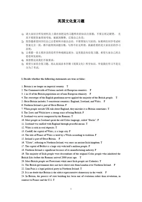
英国文化复习题1)请大家结合所发材料及上课内容把这些习题所在的知识点掌握;不要去死记硬背,尤其不要把答案带到考场,被抓到舞弊,后果自己负责;2)简答题希望同学们自己去看材料并做出总结,不要背别人写好的,如果两位同学考试时答案完全一致,都不能得到该题分数。
写得不好无所谓,我最看重的是大家良好的学习态度;3)古希腊一章主要涉及的是哲学和戏剧这部分,这里我没有给复习题,希望大家自己再去看看所发材料;4)基督教这章我们不做要求;5)希望大家结合复习题,再认真阅读本学期《英国文化》所学知识,毕竟我们学习不是完全为了考试;I. Decide whether the following statements are true or false:1. Britain is no longer an imperial country. T2. The Commonwealth of Nations include all European countries. F3. 1 in 10 of the British population are of non-European ethnicity. F4. The stereotype of the English gentleman never applied the majority of the British people. T5. Great Britain includes 3 constituent countries: England, Scotland, and Wales. F6. Northern Ireland is part of Great Britain. F7. When people outside UK talk about England, they mistake it as Britain sometimes. T8. The Scots and Welsh have a strong sense of being British. F9. Scotland was never conquered by the Romans. T10. Most people in Scotland speak the old Celtic language, called "Gaelic". F11. Scotland was unified with England through peaceful means. T12. Wales is rich in coal deposits. T13. Cardiff, the capital of Wales, is a large city. F14. The title of Prince of Wales is held by a Welsh according to tradition. F15. Ireland is part of Great Britain. F16. "Ulster", referring to Northern Ireland, was once an ancient Irish kingdom. T17. The capital of Belfast is a large city with half a million people. F18. Northern Ireland is significant because of its manufacturing industry. F19. The majority of Irish people were descendants of the original Celtic people who inhabited the British Isles before the Romans arrived 2000 years ago. T20. Most British people are Protestants while most Irish people are Catholics. T21. The British government does not have direct rule from London over Northern Ireland. F22. Sinn Fein is a legal political party in Northern Ireland. T23. It is no doubt that Britain is the oldest representative democracy in the world. F24. In Britain, the process of state-building has been one of evolution rather than revolution, in contrast to France and the U.S. T25. The oldest institution of government according to the text is the Monarchy. T26. The divine right of kings means the sovereign derived his authority from his subjects. F27. While the King in theory had God on his side, it was thought that he should exercise absolute power. F28. The term "parliament" was first officially used in 1066 to describe the gathering of feudal barons and representatives from counties and towns. F29. Britain is both a parliamentary democracy and a constitutional monarchy. T30. Britain, like Israel, has a written constitutions of the sort which most countries have. F31. Common laws are laws which have been established through common practice in the courts. T32. In the U.K., a government cannot stand for longer than five years except in exceptional circumstances. T33. The parliament can call an election sooner than five years. F34. Anyone who is eligible to vote with 500 pounds as deposit can stand as an MP. T35. Each main party is given some time on national TV to "sell" their policies. The time is not given free and has to be paid by the party. F36. The amount spent in national campaign is not limited other than that on TV. T37. The campaigns are not simply about telling people how good your policies are, but also about telling them how bad your opponents are. T38. Secrecy is not an important part of the voting process. F39. The counting of votes run over a period of a few days. F40. There are two major national parties in the U.K. according to the text. F41. Liberal Democratic Party is the newest of the major national parties. F42. By the 1880's the British economy was dominant in the world. T43. Both the U.S. and Canada overtook Britain in economy by 1900. F44. In World War II, Britain had gone heavily into debt in order to develop its manufacturing industry and borrowed large amounts from the U.S. and France. F45. Another reason for British decline is the loss of its colonies, especially India, which gained its independence in 1947. T46. In the 1970's, with the souring price of oil and high rates of inflation, Britain went through a bad period. In 1979, the Labour Party had to step down from the government. T47. The leader of the Conservatives, Margaret Thatcher started a series of reforms. An extensive programme of privatization was carried out but she did not succeed in saving the British economy. F48. Tertiary industries include banking, insurance, tourism, agriculture and the selling of goods.F49. Britain has a large sector of agriculture producing 11.6% of its national wealth. F50. According to the text, the tertiary industry produces approximately 2/3 of the national wealth.T51. The service industry in the U.K. employs 70% of the total work force. T52. The purpose of British education is not only to provide children with literacy and other basic skills but also to socialize children. T53. The state seldom interferes with the decision of when, where, how and what children aretaught. F54. The enduring feature of British education is the continuing debate over what should be taught in school and universities. F55. The 1944 Education Act made entry to secondary schools and universities "meritocratic".T56. The public schools are part of the national education system and funded by the government.F57. British universities are public bodies which receive funds from central government. T58. In Oxford and Cambridge the BA converts to an MA several years later, upon payment of a fee. TII. Choose the correct answer to each of the following.1.__________ is not considered a characteristic of London.(a) The cultural centre(b) The business centre(c) The financial centre(d) The sports centre2. ________________ is not true about the characteristics of Britain.(a) Economic differences between north and south(b) Differences of social systems between Scotland and Wales(c) Class differences between a white-collar worker and a blue-collar worker(d) Cultural differences between immigrants and the British3. _______________ can not be found in London.(a) Teahouses(b) Galleries(c) Museums(d) Theatres4. Which of the following is not true about Britain?(a) It used to be an imperial country in the world.(b) It plays an active role as a member of European Union.(c) It is a relatively wealthy and developed country.(d) It used to be one of the superpowers in the world.5. Three of the following are characteristics of London. Which of the four is the exception?(a) London is a political, economic and cultural centre of the country.(b) London has a larger population than all other cities in England.(c) London is not only the largest city in Britain, but also the largest in the world.(d) London has played a significant role in the economic construction of the country.6. The Tower of London, a historical sight, located in the centre of London, was built by___________.(a) King Harold(b) Robin Hood(c) Oliver Cromwell(d) William the Conqueror7.________ were the ancestors of the English and the founders of England.(a) The Anglo-Saxons(b) The Normans(c) The Vikings(d) The Romans8. __________ is the largest city in Scotland.(a) Cardiff(b) Edinburgh(c) Glasgow(d) Manchester9. Why did the Scottish Kings decide to form an independent singular Scottish state in the ninth century?(a) They needed a unified independent nation to fight against Viking raids.(b) They felt it necessary to develop their own industry.(c) They were threatened by the Anglo-Saxons' invasion.(d) They had to do it in order to resist the English.10. Where do the majority of people in Scotland live?(a) In the Highlands.(b) In the Lowlands.(c) In the Uplands.(d) In the west of Scotland.11. Which of the following statements is not true?(a) Wales was invaded by the Romans.(b) Wales was occupied by the Anglo-Saxons.(c) Wales was conquered by the Normans.(d) Wales was threatened by the English.12. Which of the following parties in Scotland still wants an independent Scotland?(a) The Labour Party.(b) The Liberal Party.(c) The Scottish Nationalist Party.(d) The Conservative Party.13. Scotland joined the Union by agreement of the English and Scottish parliaments ________.(a) In 1715(b) In 1688(c) In 1745(d) In 170714. Llywelgn ap Gruffudd is more than a simple historical figure for the Welsh. He is almost considered the legendary hero of Welsh nationalism because___________.(a) he became the first Prince of Wales in 1267(b) he brought the English under his control(c) he led a historic uprising against the English(d) he unified Wales as an independent nation15. In the seventeenth century, the English government encouraged people from Scotland and Northern England to emigrate to the north of Ireland, because___________.(a) they wanted to increase its control over Ireland(b) they had too many people and didn't have enough space for them to live in(c) they intended to expand their investment(d) they believed that Ireland was the best place for them16. In 1969, the first British soldiers were seen on Northern Ireland Street. They came first___________.(a) to maintain traffic order in Northern Ireland(b) to protect the Catholic people(c) to protect the Protestant people(d) to replace the Royal Ulster Constabulary since they were unable to keep social order17. Northern Ireland is the smallest of the four nations, but is quite well-known in the world for___________.(a) its most famous landmark, the "Giant's Causeway"(b) its rich cultural life(c) its low living standards(d) its endless political problems18. Faced with conflicting demands the British government chose a compromise and organised a partition of Ireland, because___________.(a) the British government wouldn't be able to control Ireland any longer by force(b) the British government intended to satisfy both sides─Catholics as well as Protestants(c) Catholics in Ireland demanded a partition of Ireland(d) Protestants welcomed the idea of partition19. Which of the following statements is not true?(a) Sinn Fein is the legal political Party in Northern Ireland.(b) Those who want to unite Northern Ireland with Britain are called Unionists.(c) Social Democratic and Labour Party is a very important political Party in Britain.(d) Those who show their loyalty to the British Crown are called Loyalists.20. In the early 1970s, the IRA___________.(a) killed many Protestants and Catholics(b) burned down the houses of Catholics(c) murdered individuals at random(d) carried out a series of bombing and shooting and attacked the security forces as their main target21. 1972 was the worst year of the political troubles in Northern Ireland, because___________.(a) 13 Catholics were shot dead by the police(b) 468 people were killed in Northern Ireland(c) the government carried out a policy known as "internment"(d) Bloody killing of 468 people fortified Catholic opposition to the British presence in Northern Ireland22. Why did the British government decide to replace the Power-Sharing policy with "direct-rule" from London?(a) The Power-Sharing policy was not accepted by the majority of Protestants.(b) The Northern Irish Parliament could not govern the province effectively.(c) The Power-Sharing policy couldn't be carried out.(d) All the above.23. Which of the following statements is not true?(a) In 1981, some convicted IRA prisoners went on a hunger-strike.(b) They demanded for the status of being "political prisoners" by starving themselves.(c) Margaret Thatcher's government gave in to their political demand.(d) The death of prisoners revitalized the political movement of Sinn Fein.24. How many counties do you know there are in Northern Ireland?(a) 26.(b) 6.(c) 32.(d) 20.25. Which of the following is not characteristic of British government?(a) It offers the Queen high political status and supreme power.(b) It is both a parliamentary democracy and a constitutional monarchy.(c) It is the oldest representative democracy in the world.(d) It has no written form of Constitution.26. Which of the following king was executed in the civil war?(a) James I.(b) James II.(c) Charles I.(d) Charles II.27. What happened in 1215?(a) It was the year of Norman Conquest in British history.(b) Forced by barons, King John signed the Magna Carta.(c) Henry IV granted the Commons the power to review money grants.(d) King Egbert united England under his rule.28. Which of the following is not true about the Great Council?(a) They included barons and representatives from counties and towns.(b) They were sometimes summoned by the kings to contribute money.(c) They later developed into what we now know as the Cabinet.(d) They represented the aristocrats as well as the communities.29. Under whose reign was the Bill of Rights passed?(a) James II.(b) William of Orange.(c) Oliver Cromwell.(d) George I.30. Which of the following is not true about the Constitution?(a) It is a document which lists out the basic principles for government.(b) It is the foundation of British governance today.(c) Conventions and Laws passed by Parliament are part of the Constitution.(d) The common laws are part of the Constitution.31. Which of the following about the Parliament is not true?(a) There are no legal restraints upon Parliament.(b) Strictly speaking, the Queen is part of the Parliament.(c) Parliament has the supreme power of passing laws.(d) Parliament has no power to change the terms of the Constitution.32. Which of the following about the Queen is not true?(a) The Queen selects the Prime Minister and the Cabinet.(b) The Queen symbolises the tradition and unity of the British state.(c) The Queen acts as a confidante to the Prime Minister.(d) The Queen is the temporal head of the Church of England.33. Which of the following about the House of Lords is not true?(a) Lords do not receive salaries and many do not attend Parliament sittings.(b) It consists of the Lords Spiritual and the Lords Temporal.(c) The lords are expected to represent the interests of the public.(d) Most of the lords in the House of Lords are males.34. Which of the following about the House of Commons is not true?(a) Members of Parliament elect the Prime Minister and the Cabinet.(b) MPs receive salaries and some other allowances.(c) MPs are expected to represent the interests of the public.(d) Most MPs belong to the major political parties.35. Which group of people can not vote in the general election?(a) Members in the House of Commons.(b) Lords in the House of Lords.(c) The UK citizens above the age of 18.(d) The UK resident citizens of the Irish Republic.36. By whom is a "vote of no confidence" decided?(a) The House of Commons.(b) The House of Lords.(c) The two major parties.(d) The Prime Minister.37. Which of the following is not true about the electoral campaigns?(a) Big parties can buy time to broadcast their policies on the television.(b) There is a limit on the amount of money candidates can spend in their constituency campaign.(c) Candidates and their supporters go door-to-door persuading voters to vote for them.(d) Candidates criticize each other's policies to show how good their own policies are.38. How many seats in the House of Commons should a party hold at least in order to win the election?(a) 651.(b) 326.(c) 626.(d) 351.39. Which of the following party adopts a "fatherly" sense of obligation to the poorer people in the society?(a) The Conservative party.(b) The Liberal Democrats.(c) The Party of Wales.(d) The Labour party.40. Which of the following description about the Conservative party is not true?(a) It has been in power for an unusually long period of time.(b) It prefers policies that protect individual's rights.(c) It receives a lot of the funding from big companies.(d) It is known as a party of high taxation levels.41. Which government lost a vote of no confidence and was forced to resign in 1979?(a) The Conservative government.(b) The Liberal government.(c) The Labour government.(d) The radical government.42. Which period of time in British history was described as "private affluence and public squalor"?(a) The 1940s.(b) The 1970s.(c) The 1980s.(d) The 1990s.43. Which of the following about the "poll tax" is not true?(a) It was introduced by the Conservative government.(b) It was introduced by the Labour government.(c) It was an attempt to change local government taxes.(d) It was criticized by many citizens.44. Who is the leader of the Labour party at present?(a) John Major.(b) Tony Blair.(c) Harold Wilson.(d) Margaret Thatcher.45. Which of the following statements about the UK economy is not true?(a) Britain remains one of the Group of Seven large industrial economies.(b) Britain has experienced a relative economic decline since 1945.(c) There has been a period of steady decreasing of living standards.(d) Some smaller economies have overtaken the UK in terms of output per capita.Answer:46. Which of the following was not the reason for the relative economic decline since 1945?(a) Britain did not invest in modern equipment and new products.(b) Britain spent a high proportion of its national wealth on the military.(c) Britain had been heavily in debt to finance the war.(d) Britain had carried out the nationalisation of the businesses.47. Which of the following livestock has the biggest number in the UK?(a) Beef cattle.(b) Dairy cattle.(c) Chicken.(d) Sheep.48. Where is the best agricultural land in Britain?(a) In the southeast of England.(b) In the northeast of England.(c) In the southeast of Scotland.(d) In the northeast of Scotland.49. Which of the following is not a company in the energy sector?(a) Shell.(b) ICI.(c) RTZ.(d) British Gas.50. Which of the following used to be the last independent car company in the UK?(a) Ford.(b) Peugeot.(c) Rover.(d) BMW.51. In aerospace industry, which two countries are ahead of Britain?(a) The U.S. and Germany.(b) The U.S. and Russia.(c) Germany and Russia.(d) France and Russia.52. Which civil airline was started in 1924 after the First World War?(a) Imperial Airways.(b) British Airways.(c) Hawker-Siddeley Aviation.(d) The British Aircraft Corporation.53. What did Frank Whittle do in 1937?(a) He invented the first jet plane.(b) He developed the first jet engine.(c) He made the first powered flight.(d) He made the trans-Atlantic flight.54. Which company became an important aero-engine manufacturer after WWI?(a) Boeing.(b) Rolls Royce.(c) McDonnel-Douglas.(d) Hawker-Siddeley Aviation.55. British Aerospace was the merger of which two companies?(a) The British Aircraft Corporation and Hawker-Siddeley Aviation.(b) The British Aircraft Corporation and Rolls Royce.(c) Hawker-Siddeley Aviation and GEC Avionics.(d) Hawker-Siddeley Aviation and Rolls Royce.56. In Britain, the great majority of parents send their children to___________.(a) private schools(b) independent schools(c) state schools(d) public schools57. In Britain, children from the age of 5 to 16___________.(a) can legally receive partly free education(b) can legally receive completely free education(c) can not receive free education at all(d) can not receive free education if their parents are rich58. If a student wants to go to university in Britain, he will take the examination called___________.(a) General Certificate of Education—Advanced(b) General Certificate of Secondary Education(c) the common entrance examination(d) General National V ocational Qualifications59. _____________ is a privately funded university in Britain.(a) The University of Cambridge(b) The University of Oxford(c) The University of Edinburgh(d) The University of Buckingham60. Which of the following is not true?(a) Parents send their children to public schools because they are rich.(b) Parents send their children to public schools because their children can get better jobs when they leave school.(c) Parents send their children to public schools because their children can have a better chance of getting into a good university.(d) Parents send their children to public schools because their children prefer to go to public schools.61. Which of the following is not a characteristic of the Open University?(a) It's open to everybody.(b) It requires no formal educational qualifications.(c) No university degree is awarded.(d) University courses are followed through TV, radio, correspondence, ect.62. In the examination called "the 11 plus", students with academic potential go to ___________.(a) grammar schools(b) comprehensive schools(c) public schools(d) technical schools63. Which of the following is not included in the National Curriculum?(a) Children must study the subjects like English, mathematics, science and so on.(b) Children must sit in A-level exams.(c) Children must pass national tests.(d) Teachers must teach what they are told.64. Which of the following is not true about the British education system?(a) It's run by the state.(b) It's funded by the state.(c) It's supervised by the state.(d) It's dominated by the state.65. _________________ would admit children without reference to their academic abilities.(a) Comprehensive schools(b) Secondary schools(c) Independent schools(d) Grammar schoolsⅢ.Topics for Discussion1. What was the British Empire? What do you know about it? In what way is the Empire still felt in Britain and in the international field?2. Why does the author say that it is not possible to sum up the British people with a few simple phrases?3. "British history has been a history of invasion". Please illustrate this point with the examples from the text. How did each of the invasions influence English culture ?2. What are some general characteristics of Scotland? How did Scotland become part of the union of Great Britain?4. Describe characteristics of Wales and Wales' unification with Great Britain.5. Are there any differences between England, Scotland and Wales in terms of cultural tradition ?6. Why is Northern Ireland, according to the author, so significant in the United Kingdom? What is the political problem there?7. What are some of the factors in Irish and English history that affect the situation in Northern Ireland today?8. Different parties and groups in the United Kingdom have different solutions to the political problem in Northern Ireland. Please sum up their different attitudes.9. Has the author offered a solution to the political problem in Northern Ireland?10. What are some of the characteristics of the British constitutional monarchy? How has the English monarchy evolved gradually to the present constitutional monarchy?11. How did the doctrine of the "divine right of kings", according to the author, lead to the English Civil War? What do you know about the causes of the English Revolution in the 17th century?12. What is the history of English parliament? What role did the parliament play in the Civil War?13. Discuss the major characteristics and the main content of the British constitution.14. Why does the author say that parliament is supreme in the British state? What functions does parliament have? What role does the Queen ( King ) and the Prime Minister play in British government?15. What kind of institution is the House of Lords? What role does it play in British government?16. Who can stand for election as an MP in the UK? Why are small parties and independent candidates powerless in the election campaign for the formation of a government?17. What are the three big parties in the UK? What are some of the similarities and dissimilarities between the three parties?18. What are some of the recent political trends in the UK? Are these trends more democratic or undemocratic? What is the author's opinion?19. The author says that John Major's conservatives remain unpopular in 1997. What reasons does the author give for this political situation?20. Please define "absolute decline and relative decline" in the UK economy. How does the authorexplain the reasons for the absolute decline and relative decline?21. What did the Conservative Party under Mrs. Margaret Thatcher promise to do to the UK national economy in 1979? The word "reform" in the national economy was also popular when Mrs. Margaret Thatcher formed the government and decided to change the UK economy. What was her radical reform program? Was the program successful according to the author?22. What are the three main areas in national economies? Describe the development of each of the three areas in the UK economy.23. The author believes that Britain, like most developed economics, has seen a relatively shrinking of the importance of secondary industry and a spectacular growth in tertiary or service industries. Why is it so? Do you see a similar growth in tertiary industries in China in the past 20 years? How is this growth related to the reform and opening up to the outside world?24. What are the purposes of the British education system? Please comment on these purposes. What are the main purposes of the Chinese education system? Are there any differences or similarities in the education of the two nations?25. How does the British education system reflect social class?26. What are the major changes that have taken place since World War II? Is British education moving towards more progress or more equality? Pick up some examples from the text to illustrate your points.27. Why does the author say that universities in Britain have been rather elitist?28. What is the Open University in Britain? What do you think of this system?。

This document was downloaded from the Penspen Integrity Virtual Library For further information, contact Penspen Integrity:Penspen IntegrityUnits 7-8St. Peter's Wharf Newcastle upon TyneNE6 1TZUnited KingdomTelephone: +44 (0)191 238 2200 Fax: +44 (0)191 275 9786 Email: integrity.ncl@ Website: When is Corrosion Not Corrosion? A Decade of MFL PipelineInspection.Paul Tims, TotalFinaElf Exploration Norge AS, Stavanger, NorwayOwen Wilson, Andrew Palmer and Associates, Aberdeen, UKAbstractTotalFinaElf Exploration UK (TFEEUK), as the technical operator of the twin 32” Frigg gas export pipelines between the Frigg field and the St. Fergus gas terminal regularly inspect the pipelines with intelligent pigs to demonstrate their integrity.Inspections of one of these pipelines found several significant defects that appeared to grow over time, to the point where the pressure at which the pipeline could safely be operated required to be reduced.To restore the pressure-retaining capability of the pipeline to its design level, a section of pipeline was replaced and a sample containing the pressure-limiting defects was recovered to the surface. A physical survey of the corroded pipe joints discovered that the reported “corrosion” was not present but found instead a layer of ferrous debris adhered to the pipe wall. The interpretation of the debris as corrosion highlights the limitations of using an inferred inspection technique in an environment where no complementary inspection is practicable.TFEEUK continue to regularly inspect these pipelines using intelligent pigs to demonstrate their integrity.IntroductionDuring a routine survey in 1990 of one of the Frigg to St Fergus 32” Gas Export pipelines operated by TotalFinaElf Exploration UK (TFEEUK), a Magnetic Flux Leakage (MFL) inspection tool detected several significant defects. The results and the subsequent analysis and investigation instigated a programme of regular inspection that continued until 1999. On the strength of worsening results, the pipeline’s Maximum Allowable Operating Pressure (MAOP) was down-rated twice in the same period.The opportunity to bring the most severely corroded pipe joints to the surface presented itself when the worst corroded section of pipeline was bypassed in 2001. A physical survey of thecorroded pipe joints discovered that the reported “corrosion” was not present but found instead, a layer of ferrous debris adhered to the pipe wall.This paper discusses:• The results and implications of the inspections.• The work performed to demonstrate the continued safe operation of the pipeline.• The results of a physical survey of the pressure-limiting “corrosion” defects.• The possible origins of the ferrous debris layer.• Work that has been done to assess the effect of the debris on the behaviour of MFL signals.Inspection ResultsThe first inspection of the line, conducted in 1990, highlighted general corrosion of a low level, with 141 significant defects with peak metal loss depth ranging from 20% to 48% wall thickness. Throughout the four successive inspections in 1992, 1996, 1997 and 1999, the number of defects increased, and the worst features became progressively deeper.A summary of the inspection results is presented in Table 1 in Appendix A. The numbers of defects are solely indicative as several of the inspections only reported on selected sections the pipeline rather than the full length. Furthermore, over the 10 year period, detection and reporting thresholds improved considerably resulting in defects being reported that may have been present earlier, but that were either below the detection or reporting thresholds. This is clearly evident in results of the 1996 and 1999 inspections – the only inspections to report on the entire length of the pipeline. The 1996 inspection reported a total of 7863 features, whereas the 1999 inspection reported 43918 features. The distribution of corrosion features (including the worst defects) over a section of the pipeline is shown in Appendix D. Worth noting is the approximate symmetry of the corrosion features around an axis running along the 6 o’clock position in the pipeline. Such corrosion patterns are not uncommon in pipelines and are normally a function of corrosion occurring at a water/product interface, the position of which varies with the vertical profile of the line.1 The 1990 inspection was only of the upstream (Northern) half of the pipeline – some 185 km. The downstream (Southern) half of the pipeline – approximately 175 km in length – was inspected in 1991.20 significant defects with peak metal loss ranging from 10% to 25% of wall thickness were reported in this section of the line.Table 1 also shows that, apart from the first inspection in 1990, the depth of the deepest feature appeared to increase steadily over time. When the data is reanalysed using a consistent analysis and sizing model, however, the depth is of the deepest feature is much more consistent over time.The worst features were, however, consistently detected over the period. One of the significant characteristics of the worst features was their general stability in terms of location and shape. The evolution of the dimensions of the worst feature over time is shown in Table 2 in Appendix A. The effects of the different analysis and sizing models can clearly be seen on the data presented in Table 2 – when analysed using the model in use at the time of each original inspection, the defect dimensions (principally length and depth) are seen to increase steadily over the 10 year period. When analysed using a consistent model (in this case, the model in use at the time of the 1997 inspection), the defect dimensions are much more consistent, particularly with respect to depth, although the defect length still clearly increases over the period from 1990 to 1996.The evolution of the magnetic signal of this defect can be seen in the series of diagrams in Appendix B. Two greyscale images of the more severe features are also presented in Appendix B. The images are broadly similar, but that from the 1999 inspection clearly shows several lower level features adjacent to the main line of features. These are represented graphically in Appendix C.The worst defect was long and thin in shaped and situated in the 6 o’clock position. The analysis of the magnetic flux readings characterised the feature as an initially deep feature, with a step to a shallower plateau, on which further pitting corrosion was identified in the later surveys.The other notable aspect of the corrosion was that the worst features were concentrated in a very small number of pipe joints. As time progressed, the 8 limiting features in terms of the pressure retaining capability of the entire pipeline were confined to 3 pipe joints distributed over an 8 km length of the pipeline. 6 out of the 8 pressure limiting features were contained within the same pipe joint.Corrosion MechanismThis highly localised corrosion led to an investigation of the steel properties of particular pipe joints. The pipeline was constructed with pipe joints from four different manufacturers, so there was speculation that one type of steel was more susceptible to the corrosion being experienced. When the corrosion was cross-referenced with the different steels, there seemed to be a strong correlation between the more severe corrosion and one of thesemanufacturers.The production over time was also investigated to establish whether there were any production upsets that might have introduced a corrosion mechanism into the otherwise apparently innocuous dry gas environment of the pipeline. It turned out that wet condensate had, in the past, been batched in the pipeline, and that the corrosion inhibition of these batches may not have been efficient. Furthermore, a wet buckle had occurred during the installation of the pipeline in the mid-1970’s around the location of the worst corrosion. It was suspected that this may have increased the propensity for linepipe corrosion in this area.The combination of the potentially susceptible steel and a corrosion mechanism gave a plausible explanation of the corrosion being reported.Down-ratingThe survey results in 1997 caused the most significant problem in terms of the integrity of the pipeline. The worst features failed the Line Pipe Corrosion Group Sponsored Project (LCGSP)2 defect assessment criteria (subsequently to become DnV RP F101), so a Finite Element Analysis (FEA) study was performed on the worst feature and the surrounding features to demonstrate the residual pressure retaining capability of the pipeline.The FEA study considered five combinations of potentially interacting defects contained in the worst affected pipe joint. The study also investigated the effects of the inspection tool measurement tolerances on the predicted defect failure pressures. The analyses determined the predicted failure pressures for the various defect combinations and showed that, although interaction between the d efects was predicted to occur, the effects on failure pressure were small – less than a 2% reduction over the predicted failure pressure of the single worst defect. A Von Mises stress distribution for one of the defect combinations analysed is shown in Appendix E.The failure pressures predicted by the FEA study showed that the depth of the worst feature recorded was beyond the limit of what could be demonstrated to be acceptable with the design MAOP. The step was therefore taken to down-rate the pipeline by 20 bar from 148.9 barg to 128 barg.The focus of the 1999 survey was to ensure that the corrosion had arrested (the practice of batching wet inhibitor was stopped before the 1997 survey, however as the growth mechanism was a hypothesis further inspection was required to test it) and the pipeline could2 Total Oil Marine, the Operator of the pipeline at the time, was a member of the LCGSP.continue to be operated safely at the down-rated pressure. To ensure repeatability, the same inspection tool was used as the 1997 survey, with the same sensor array and electronic package. When the inspection reports were delivered, however, a further 3% reduction in the wall thickness of the worst feature was reported (from 48% of wall thickness to 51% of wall thickness, as shown in Tables 1 and 2 of Appendix A).After much discussion with the inspection contractor it was discovered that the analytical process for interpreting the magnetic flux measurements from the sensor had, in fact, been upgraded in the time between the two surveys as this was felt to give a more accurate interpretation of the measurements. The question of whether the feature had physically deepened therefore remained.To answer this question, the 1999 results were re-interpreted with the 1997 analytical model, and the results reported the same defect depth as was previously reported with the 1997 data (as shown in Tables 1 and 2 of Appendix A). This gave confidence that the feature had not grown. Given, however, that the 1999 analytical process was considered more accurate than the 1997 model, the decision was made to re-analyse the fitness-for-purpose of the reported defects using the 1999 feature dimensions. This resulted in the down-rating of the pipeline by a further 5 bar to 123 barg. The results from 1997 and 1999 for the worst defects, and the re-interpreted results from 1999 are shown in Appendix C.Bypass and Pipe Joint Cut-outIn 2001, the installation of a new section of pipeline to be tied in to the existing pipeline presented the opportunity to by-pass the worst areas of corrosion and restore the MAOP of the pipeline to its design level – itself an important consideration in maximising the throughput capacity for new gas.In order to accurately determine the position of the corrosion in the pipeline, it was necessary to establish a common reference between the internal a nd external reference system (the tolerances of internal and external survey systems mean that common points must be used for accurate cross-referencing between different survey types). Powerful magnets were therefore installed on the exterior of the pipeline, using an ROV installed clamping system before the 1999 inspection.Locations for the magnets were chosen bounding the worst area of corrosion to be bypassed, also attempting not to hide significant features under the magnets themselves. The positioning of the magnets and an overall view of the reported corrosion can be seen in Appendix D. These magnets were used as reference points for the bypass tie-in, and were also used to locate the pipe joints for cutting out and recovery to the surface.An important part of the identification of the pipe joints to cut out was the correlation of the pigging weld record and the lay record data. This exercise was done using known construction features that were detailed in the lay record and also detectable by the inspection tool. The magnets could not be used for this purpose, because it was not possible to accurately establish which pipe joints the magnets had been mounted on. The drawback with the construction references was that they were so far apart, and a lso far from the reported corrosion.The most useful data recorded in the pigging and lay records turned out to be the pipe joint lengths. The variation in the lengths of the pipe joints was recorded during the construction of the pipeline and was also quite accurately reported in the pigging record. The comparison of these lengths proved, therefore, to be the basis for the final adjustments for the correlation of the data. An example of the correlation around the cut points can be seen in Appendix F. Another feature of the construction that proved useful was the fact that some of the 12m long pipes were made up of two shorter lengths. These “jointer” pipes showed up well in the pigging record as an extra weld.As both the magnets and corrosion were detected by the 1999 internal inspection, calculating the physical distance from the magnet to the cut points to a high degree of accuracy and certainty was therefore possible. These distances were translated onto the as-found magnet and pipeline positions, and tracked across the seabed. Two pipe joints, one containing the worst corrosion features, were then cut out of the bypassed section of pipeline with a diamond-wire saw and brought to the surface.Investigation of Physical CorrosionThe recovered pipe j o ints were transported to the yard, and an investigation of the internal surface conducted. The original weld number paint markings from construction could still be seen on the external weight coat, and these corresponded to the expected weld numbers, confirming that the correct pipe joints had been recovered.Both pipe joints were examined internally, their size allowing good access for visual inspection. The pipe joint that contained the worst “corrosion” was found not to contain any corrosion features, but instead a layer of apparently rusty material was seen to be deposited on the bottom of the pipeline centred around the 5 – 5.30 o’clock position for a length of approximately 10 m (starting and ending approximately 1 m inward of the ends of the pipe joint). Two white, calcareous deposit lines were visible around the 3 o’clock and 9 o’clock running along the length of the pipe (these were later identified as Magnesium Hydroxide). These appeared to be some form of interface mark (essentially a “tide mark”), and confirmedthe original orientation of the joints in the pipeline. The adjacent pipe joint contained no debris layer or apparent corrosion.The layer of rusty material formed a near-solid “sheet” varying in thickness typically around 10 mm, but u p to 20 mm, and up to 220 mm wide (thinner at the upstream end than the downstream end). This “crust” was hard, brittle, and could be kicked off the pipe wall in chunks although it was surprisingly resilient to impact and abrasion. After removal from the pipe and exposure to the atmosphere for a few weeks, the crust would crumble, presumably as binding agents evaporated. No significant corrosion was evident under the debris layer. The volume of material contained in the debris crust was estimated at between 5 and 10 litres.On close examination the material forming the crust was found to be made of tightly packed, tiny spherical metallic balls, typically around 1 mm in diameter, relatively consistent in size and apparently bound together by corrosion products. When sectioned and examined under a microscope, some of the spheres exhibited cracks and some were hollow. X-ray diffraction and spectroscopy analyses were performed on samples from various parts of the debris layer. The analyses identified Iron, Carbon and Silicon elements in the metallic spheres. The corrosion product was found to comprise mostly of oxides of iron. Traces of Calcium, Aluminium and Magnesium were also identified.Photographs of the defect crust in-situ, removed from the pipe, and sectioned and magnified are shown in Appendix G.As noted above, the debris crust was surprisingly resilient to impact and abrasion. That the layer had apparently been present in the pipeline for many years is worthy of note - many heavy duty cleaning pigs, some fitted with powerful magnets had been run down the pipeline over its lifetime. Furthermore, several MFL intelligent pigs were also run down the pipeline. Experience with these tools suggests that they are amongst the most efficient cleaning tools available due their weight, brushes and powerful magnets.If a layer of hard debris such as was found in the pipeline had been suspected at any stage during operation, pin-wheel type pigs could have been run to try and remove it. Given the nature of the gas flow through the pipeline and the results of the cleaning pigging, however, there was never any reason to suspect that such debris might be present.It should be noted that the presence of the debris layer in the recovered pipe joint does not, on its own, invalidate the internal corrosion reported elsewhere in the line by the inspection tool.Possible Sources of the DebrisSeveral potential sources have been identified for the debris crust found in the pipeline:• Product from flame cutting.• Weld spatter from burn-through of the weld root during construction.• Iron grit blast.The significant quantity of material found deposited in the pipe length suggests that flame cutting was unlikely – whilst occasional welds may have been cut out, the volume of material suggests a more frequent event.Weld spatter is a possible source of the material, but it is not considered credible that so much material could come from only the welds at either end of the pipe joint.Spent grit blast material from part of the construction process is certainly a possible cause. The detail of the fabrication and construction procedures used during the preparation of the linepipe at the mill and coating yard, and then during construction on the lay-barge have not been investigated, but it is certainly conceivable that shot-blasting was carried at some point, either as a standard operation, or, for example, as part of a frequent repair process.What is likely is that small amounts of material, however they arrived in the pipeline, have been collected and transported along the pipeline by early pigging operations, perhaps during pre-commissioning activities. This material has then been deposited and smeared along the pipe wall. Corrosion within the layer, the drying effects of the gas flow, and further pigging runs combined to compress and bind the layer into the hard crust that was found. The above explanations are neither conclusive nor mutually exclusive.Metallic Crust Laboratory SimulationThe inspection contractor who performed the surveys of the pipeline instigated an investigation into the effects of the debris crust on MFL signals.Samples of the debris crust were broken down, mixed with glue and spread on coupon of test steel. The density of the glue/debris mix was kept consistent with that of the original debris crust.Magnetic flux data was collected from the test coupon using a system that simulated the way in which the inspection tool gathers data. The bare test coupon, containing two artificial defects, was mapped first. The glue/debris mix was then used to fill in one of the defects and the survey repeated. The surveys were further repeated with glue/debris layers of graduallyincreasing thickness, from 2 mm to 10 mm, over a general area, including one of the defects. The results of the work demonstrated that, as expected, the presence of the metallic debris layer had a significant effect on the MFL signals. Any defects under the layer became much less distinct as the thickness of the debris layer increased (a 10 mm thick layer could cause a change in predicted defect depth of as much as 40%).The effects of variations in the debris layer were not investigated. It is believed that local variations in thickness, density and potentially other properties could produce MFL signals that could be falsely interpreted as a pipe wall defect. Features such as a rough edge to the debris crust, or a missing chunk of crust are quite conceivable and their effects on MFL signals need to be investigated. TFEEUK are pursuing this in conjunction with the inspection contractor.ConclusionThe use of MFL technology has been demonstrated to give misleading results in this circumstance. What this highlights is the fact that the technology is an inferred inspection technique, measuring magnetic flux signals that can be misinterpreted. In certain cases, it therefore introduces an element of doubt or risk when using this technology if it is being solely relied on to determine the integrity of a pipeline.Where uncertainty exists, and it is possible and practicable, a complementary inspection method should be employed. For land pipelines, this usually takes the form of an excavation and external inspection method such as ultrasonic tools. In the case of a subsea pipeline, whilst possible, an external inspection is, due to the environment, significantly more hazardous and normally very costly and may therefore not be desirable or practicable.A complementary internal inspection with an ultrasonic tool would have been possible, although again, may not always be practicable in a gas pipeline due to the requirement to run the tool in a slug of liquid. There is also a suspicion that, given the granular nature of the debris crust, the ultrasonic signal would have been attenuated to the point of non-return, resulting in further uncertainty. The only other internal inspection technique that may have highlighted the true nature of the crust is a visual inspection. This technology is becoming available for longer pipelines with the development of digital storage devices.Having said that, the results seemed at the time very conclusive, and all the evidence corroborated the assumption of corrosion, so it seemed unnecessary to pursue any complementary inspection. There was no reason to suspect the presence of the debris layer, and no precedent in either TotalFinaElf operating experience or that of the inspection contractor that raised any suspicions as to the real nature of the reported features. The mainlessons learned from this is to be vigilant of any assumptions, to explore all possibilities, and to bare in mind it may be cost effective to perform complementary inspections in certain circumstances.Magnetic Flux Leakage remains a valid inspection technique that produces generally accurate, reliable and repeatable results in the majority of circumstances. TotalFinaElf, both in the UK and Worldwide continue to employ MFL inspection tools from all the major inspection contractors to assist in ensuring the integrity of their assets, including the pipeline discussed in this paper.Appendix A – Summary of Inspection FindingsYear19901 19922 19963 1997519996 No. of Features > 60% WT 0 0 0 0 0No. of Features > 40% WT 4 3 4 5 14No. of Features > 20% WT 14 319 184 195 242No. of Features < 20% WT N/A 3572 7680 4568 43676Total Number of Features 14 3891 7864 4764 43918Originally Reported Depth of48% 42% 43%4 48% 51% Worst Feature (% WT)Revised Depth of Worst Feature47% 46% 46% 48% 48%(%WT)7Table 1 – Summary of Inspection DataNotes:1. The 1990 inspection only covered the upstream (Northern) half of the pipeline – some 185 km.2. The 1992 inspection only reported on a 10 km section containing the worst defects. This was locatedbetween PK 304 and PK 314 (46 km to 56 km downstream of launch).3. The 1996 inspection reported on the whole 364 km pipeline length.4. A defect with a depth of 53% wall thickness was reported in a thick-walled length of the pipeline. Thedepth noted in Table 1 is the deepest defect reported in the main section of the pipeline.5. The 1997 inspection reported on 7 selected areas. Of the 4764 features reported, 1994 were categorisedas of manufacturing origin.6. The 1999 inspection reported on the whole 364 km pipeline length. Of the 43918 features reported, 12395were categoris ed as of manufacturing origin.7. The previous inspection data was reanalysed in 1997 using the same analysis and sizing models. The1999 data was also reanalysed using the 1997 sizing models.Inspection Data Analysis Model Axial Length(mm)CircumferentialWidth (mm)Depth (% WT)1990 1990 18 65 381990 1997 156 56 47 1992 1992 15 63 42 1992 1997 180 51 46 1996 1996 250 65 44 1996 1997 260 51 46 1997 1997 260 50 48 1999 1999 260 50 51 1999 1997 260 50 48Table 2 – Dimensions of Worst DefectNote : Data in italics is all analysed using the 1997 data analysis and sizing model.Appendix B – Magnetic Signals for the Worst DefectsFigure B1 – Magnetic Flux Leakage Signal, Worst Defects, 1990Figure B2 – Magnetic Flux Leakage Signal, Worst Def ects,1992Figure B3 – Magnetic Flux Leakage Signal, Worst Defects,1996Figure B4 – Magnetic Flux Leakage Signal, Worst Defects,1997Figure B5 – Magnetic Flux Leakage Signal, Worst Defects,1999Figure B6 – Greyscale MFL Signal, Worst Defects,1997Figure B7 – Greyscale MFL Signal, Worst Defects,1999Note: The approximate dimensions of the greyscale plots is 4.0 m (axial length) x 0.8 m circumferential lengthAppendix C – Inspection Results, Worst CorrosionFigure C1 – 1999 Inspection Data, Assessed Using 1999 Sizing ModelFigure C2 – 1997 Inspection Data, Assessed Using 1997 Sizing ModelFigure C3 – 1999 Inspection Data, Re-assessed Using 1997 Sizing ModelAppendix D – FEA Study, Von Mises Stress DistributionFigure D1 – Von Mises Stress Distribution for Worst Defect CombinationAppendix E – Magnet Locations and General Corrosion PlotFigure E1 – General Corrosion Plot and Magnet Positions for Section of PipelineAppendix F – Correlation Between Pigging and Lay RecordsWeld No Piece No Plate No Length (m) Anode/BA Weld No Pig Dist B0247711 44680 12.28344 None 12.3 41220 A 1915B0246136 241406 12.31392 MAGNET 12.3 41230 A 1916B0244830 243170 12.10056 None 12.1 41240 A 1917B0247381 42798 12.16152 BA 12.2 41250 A 1918B0248600 43614 12.31392 None 12.3 41260 A 1919 3.8 41270 B0200236 236200 12.58824 None 8.8 41280 A 1920B0247376 41382 11.7348 None 11.7 41290 A 1921B0248011 41358 12.31392 None 12.3 41300 A 1922B0248286 42288 12.31392 None 12.3 41310 A 1923B0245279 242378 11.85672 None 11.9 41320 A 1924B0246016 241678 11.5824 Anode 11.6 41330 A 1925B0245870 242866 12.00912 None 12.0 41340 A 1926B0248259 43492 12.192 None 12.2 41350 A 1927B0247734 47734 12.31392 None 12.3 41360 A 1928B0244879 243420 12.28344 None 12.3 41370 A 1929B0247509 42296 11.8872 None 11.9 41380 A 1930B0248831 43302 11.91768 None 11.9 41390 A 1931B0245817 243830 12.28344 BA 12.3 41400 A 1932B0246838 243426 11.94816 None 12.0 41410 CUT POINT A 1933B0244745 243476 12.31392 None 12.3 41420 CUT POINT A 1934B0247423 41952 11.70432 None 11.7 41430 CUT POINT A 1935B0248636 43512 12.31392 None 12.3 41440 A 1936B0249059 41384 11.82624 None 11.8 41450 A 1937B0247680 41360 12.31392 None 12.3。
模具制造业常用英语中文解说作者:佚名来源:不详发布时间:2008-3-9 0:58:18 发布人:admin减小字体增大字体Aabrasive grinding 强力磨削 L3abrasive[E'breisiv] a.磨料的, 研磨的 L2,3absence ['AbsEns] n.. 不在,缺席 L17accesssory[Ak'sesEri] n.附件 L10accommodate[E'kCmEdeit] v. 适应 L5accordingly[E'kC:diNli] adv.因此,从而,相应地 L7,13accuracy['AkjurEsi] n精度,准确性 L1,3actuate['Aktjueit] vt.开动(机器), 驱动 L8adequate['Adikwit] a. 足够的 L13adhesive[Ed'hi:siv] n. 粘合剂 L22adjacent[E'dVeisnt] a. 邻近的 L13adopt[E'dCpt] vt. 采用 L4advance [Ed'vA:ns] n.进步 L7advisable [Ed'vaizbl] adj. 可取的 L20agitate['AdViteit] v. 摇动 L2a large extent 很大程度 L4,13algorithm ['Al^EriTEm] n. 算法 L6align [E'lain] v 定位,调准 L17alignment[E'lainmEnt] n. 校直 L11all-too-frequent 频繁 L17allowance[E'lEuens] n. 容差, 余量 L5alternate['C:ltEnit]v.交替,轮流 L1alternative[C:l'tE:nEtiv] n. 替换物 L3alternatively[C:l'tE:nEtivli] ad. 做为选择, 也许 L5aluminiun[7Alju'minjEm] n.铝 L2ample['Ampl] adj. 充足的 L20analysis [E'nAlEsis] n. 分析 L6ancillary['AnsilEri] a.补助的, 副的 L4angular ['A^julE] adj. 有角的 L20annealing[E'li:liN] n.退火 L2aperture ['ApEtFE] n.孔 L17applied loads 作用力 L1appropriate [E'prEuprieit] a. 适当的 L6,20arc[a:k] n.弧, 弓形 L10arise[E'raiz] vi. 出现, 发生 L21arrange[E'reidV] v. 安排 L12article['a:tikl] n.制品, 产品 L21ascertain[7AsE'tein] vt. 确定, 查明 L1assemble[E'sembl] vt.组装 L4attitude ['Atitju:d] n 态度 L17auxiliary [C:^'ziljEri]adj. 辅助的 L8avoid[E'vCid] v.避免 L7axis['Aksis] n.轴 L5axle['Aksl] n.轮轴, 车轴 L1Bbackup['bAk7Qp] n. 备份 L9batch [bAtF] n 一批 L17bearing['bZEriN] n.轴承,支座 L21bed[bed] n. 床身 L5behavior[bi'heivjE] n. 性能 L1bench-work 钳工工作 L4bend[bend] v.弯曲 L1beneath[bi'ni:W] prep在···下 L4bin [bin] n. 仓,料架 L19blank [blANk] n. 坯料 L20blank [blANk] v. 冲裁,落料 L17blanking tool 落料模 L17blast [blQst] n.一阵(风) L18blemish['blemiF] n. 缺点, 污点 L13bolster['bEulstE] n. 模座,垫板 L4,5boost[bu:st] n. 推进 L9boring['bC:riN] n.镗削, 镗孔 L4,5bracket ['brAkit] n. 支架 L19brass [brAs] n.黄铜 L2break down 破坏 L1breakage ['breikidV] n.破坏 L17bridge piece L16brine[brain] n. 盐水 L2brittle['britl] adv.易碎的 L1buffer [bQfE] n.缓冲器 L8built-in 内装的 L9bulging [bQldViN] n. 凸肚 L22burr [bE:] n. 毛刺 L17bush [buF] n. 衬套 L17bush[buF]n. 衬套 L5by far (修饰比较级, 最高级)···得多, 最 L3 by means of 借助于 L5Ccabinet ['kAbinit] n.橱柜 L7call upon 要求 L17carbide['ka:baid] n.碳化物 L10carburzing['ka:bjuretiN] n. 渗碳 L2carriage['kAridV] n.拖板, 大拖板 L5carry along 一起带走 L18carry down over 从···上取下 L21carry out 完成 L17case hardening 表面硬化 L2case[keis] n. 壳, 套 L2cast steel 铸钢 L17casting['ka:stiN] n. 铸造,铸件 L3category['kAtE^Euri] n. 种类 L6,15caution ['kC:FEn] n. 警告,警示 L17cavity and core plates 凹模和凸模板 L11cavity['kAviti] n.型腔, 腔, 洞 L4,10centre-drilling 中心孔 L5ceramic[si'rAmik] n.陶瓷制品 L3chain doted line 点划线 L11channel['tFAnl] n.通道, 信道 L8characteristic[kArEktE'ristik] n.特性 L1check[tFek] v.核算 L21chip[tFip] n.切屑, 铁屑 L3chuck [tFQk] n.卡盘 L5,8chute [Fu:t] n. 斜道 L19circa ['sEkE:] adv. 大约 L7circlip['sE:klip] n.(开口)簧环 L22circuit['sE:kit] n. 回路, 环路 L13circular supoport block L5circulate['sE:kjuleid] v.(使)循环 L13clamp [klAmp] vt 夹紧 L17clamp[klAmp] n.压板 L12clay[klei] n. 泥土 L2,7clearance ['kliErEns] n. 间隙 L17clip [klip] vt. 切断,夹住 L19cold hobbing 冷挤压 L4cold slug well 冷料井 L12collapse[kE'lAps] vi.崩塌, 瓦解 L22collapsible[kE'lApsEbl] adj.可分解的 L22combination [kCmbi'neiFEn] n. 组合 L18commence[kE'mens] v. 开始, 着手 L16commence[kE'mens]v. 开始 L21commercial [kE'mE:FEl] adj. 商业的 L7competitive[kEm'petitiv] a. 竞争的 L9complementary[7kCmpli'mentEri] a. 互补的 L5 complexity [kem'pleksiti] n.复杂性 L8complicated['kCmplEkeitid] adj.复杂的 L2complication [kCmpli'keiFEn] n. 复杂化 L5,20compression [kEm'preFEn] n.压缩 L1comprise[kEm'prais] vt.包含 L16compromise['kCmprEmaiz] n. 妥协, 折衷 L13 concern with 关于 L6concise[kEn'sais] a. 简明的, 简练的 L9confront[kEn'frQnt] vt. 使面临 L14connector[kE'nektE] n. 连接口, 接头 L14consequent['kCnsikwEnt] a. 随之发生的, 必然的 L3 console ['kCnsoul] n.控制台 L8consume [kEn'sjum] vt. 消耗, 占用 L7consummate [kEn'sQmeit] vt. 使完善 L6container[kEn'teinE] n. 容器 L11contingent[ken'tindVEnt] a.可能发生的 L9contour['kEntuE] n.轮廓 L5,21conventional[kEn'venFEnl] a. 常规的 L4converge[kEn'vE:dV] v.集中于一点 L21conversant[kCn'vE:sEnt] a. 熟悉的 L15conversion[kEn'vE:FEn] n 换算, 转换 L7conveyer[ken'veiE] n. 运送装置 L12coolant['ku:lEnt] n. 冷却液 L13coordinate [kEu'C:dnit] vt. (使)协调 L8copy machine 仿形(加工)机床 L4core[kC:] n. 型芯, 核心 L2,4corresponding [ka:ri'spCdiN] n.相应的 L7counteract [kauntE'rAkt] vt. 反作用,抵抗 L20 couple with 伴随 L20CPU (central processing unit) 中央处理器 L9 crack[krAk ] v.(使)破裂,裂纹 L1,17critical['kritikl] adj.临界的 L2cross-hatching 剖面线 L16cross-section drawn 剖面图 L11cross-slide 横向滑板 L5CRT (cathoder-ray tube) 阴极射线管 L9crush[krQF]vt.压碎 L1cryogenic[7kraiE'dVenik ]a.低温学的 L1crystal['kristl] adj.结晶状的 L1cubic['kju:bik] a. 立方的, 立方体的 L3cup [kQp] vt (使)成杯状, 引伸 L18curable ['kjurEbl] adj. 可矫正的 L20curvature['kE:vEtFE] n.弧线 L21curve [kE:v] vt. 使弯曲 L20cutter bit 刀头, 刀片 L3cyanide['saiEnaid] n.氰化物 L2Ddash [dAF] n. 破折号 L6daylight ['deilait] n. 板距 L12decline[di'klain] v.下落,下降,减少, L3,9deform[di'fC:m] v. (使)变形 L1,3demonstrate['demEstreit ] v证明 L21depict[di'pikt ] vt 描述 L18deposite [di'pCzit] vt. 放置 L20depression[di'preFEn] n. 凹穴 L12descend [di'sent] v. 下降 L20desirable[di'zairEbl] a. 合适的 L2detail ['diteil] n.细节,详情 L17deterioration[ditiEri:E'reiFEn] n. 退化, 恶化 L12 determine[di'tE:min] v.决定 L16diagrammmatic[7daiEgrE'mAtik].a.图解的,图表的 L10 dictate['dikteit] v. 支配 L12die[dai] n.模具, 冲模, 凹模 L2dielectric[daii'lektrik] n. 电介质 L10die-set 模架 L19digital ['didVitl ] n.数字式数字, a.数字的 L3,6 dimensional[dddi'menFEnl] a. 尺寸的, 空间的 L3 discharge[dis'tFa:dV] n.v. 放电, 卸下, 排出 L3 discharge[dis'tFa:dV] v.卸下 L8discrete [dis'cri:t] adj. 离散的,分立的 L7dislodge[dis'lCdV] v. 拉出, 取出 L12dissolution[disE'lu:FEn] n.结束 L9distinct [dis'tiNkt] a.不同的,显著的 L6distort [dis'dC:t] vt. 扭曲 L20distort[dis'tC:t] vt. (使)变形, 扭曲 L1distributed system 分布式系统 L9dowel ['dauEl] n. 销子 L19dramaticlly [drE'mAtikli] adv. 显著地 L7drastic ['drAstik] a.激烈的 L17draughting[dra:ftiN] n. 绘图 L16draughtsman['drAftsmEn] n. 起草人 L16drawing['drC:iN] n. 制图 L11drill press 钻床 L8drum [drQm] n.鼓轮 L8dual ['dju:El] adv. 双的,双重的 L18ductility [dQk'tiliti ] n.延展性 L1,21dynamic [dai'nAmik ] adj 动力的 L6Eedge [edV] n .边缘 L20e.g.(exempli gratia) [拉] 例如 L12ejector [i'dVektE] n.排出器, L18ejector plate 顶出板 L16ejector rob 顶杆 L5elasticity[ilA'stisiti] n.弹性 L1electric dicharge machining 电火花加工L3electrical discharge machining电火花加工 L10electrochemical machining 电化学加工L3electrode[i'lektrEud] n. 电极 L10electro-deposition 电铸 L4elementary [elE'mentEri] adj.基本的 L2eliminate[i'limineit] vt. 消除, 除去 L10elongate[i'lCN^et] vt. (使)伸长, 延长 L1emerge [i'mE:dV] vi. 形成, 显现 L20emphasise['emfEsaiz] vt. 强调 L4endeavour[en'devE] n. 尽力 L17engagement[in'^eidVment] n. 约束, 接合 L22 enhance[in'hAns] vt. 提高, 增强 L9ensure [in'FuE] vt. 确保,保证 L17envisage[in'vizidV] vt.设想 L15erase[i'reis] vt. 抹去, 擦掉 L16evaluation[i'vAlju7eiFEn] n. 评价, 估价L1eventually[i'vEntFuEli ] adv.终于 L21evolution[evE'lu:FEn] n.进展 L16excecution[eksi'kju:FEn] n. 执行, 完成 L9 execute ['ekskju:t] v. 执行 L8exerte [i^'zE:t] vt. 施加 L20experience[iks'piriEns] n. 经验 L16explosive[iks'plEusiv]adj.爆炸(性)的 L22extend[eks'tend] v. 伸展 L2external[eks'tE:nl] a. 外部的 L5,11extract[eks'trAkt] v. 拔出 L14extreme[iks'tri:m] n. 极端 L13extremely[iks'tri:mli] adv. 非常地 L12extremity[iks'tmiti] n. 极端 L13extrusion[eks'tru:VEn] n. 挤压, 挤出 L3FF (Fahrenheit)['fArEnhait]n.华氏温度 L2fabricate ['fAbrikeit] vt.制作,制造 L7facilitate [fE'siliteit] vt. 帮助 L6facility[fE'siliti] n. 设备 L4facing[feisiN] n. 端面车削 L5fall within 属于, 适合于 L15fan[fAn] n.风扇 L7far from 毫不, 一点不, 远非 L9fatigue[fE'ti^] n.疲劳 L1feasible ['fi:zEbl] a 可行的 L18feature ['fi:tFE] n.特色, 特征 L7,17feed[fi:d] n.. 进给 L5feedback ['fi:dbAk] n. 反馈 L8female['fi:meil] a. 阴的, 凹形的 L11ferrule['ferEl] n. 套管 L14file system 文件系统 L9fitter['fitE] n.装配工, 钳工 L4fix[fiks] vt. 使固定, 安装, vi. 固定 L11fixed half and moving half 定模和动模 L11 flat-panel technology 平面(显示)技术 L9flexibility[fleksi'biliti] n. 适应性, 柔性 L9flexible['fleksEbl] a. 柔韧的 L13flow mark 流动斑点 L13follow-on tool 连续模 L18foregoing ['fC:'^EuiN]adj. 在前的,前面的L8foretell[fC:'tell] vt. 预测, 预示, 预言 L9forge[fC:dV] n. v. 锻造 L3forming[fC:miN] n. 成型 L3four screen quadrants 四屏幕象限 L9fracture['frAktFE] n.破裂 L21free from 免于 L21Ggap[^Ap] n. 裂口, 间隙 L10gearbox['^iEbCks] n.齿轮箱 L5general arrangement L16govern['^QvEn] v.统治, 支配, 管理 L13grain [^rein] n. 纹理 L20graphic ['^rAfik] adj. 图解的 L6grasp [^rAsp] vt. 抓住 L8grid[^rid] n. 格子, 网格 L16grind[^raind] v. 磨, 磨削, 研磨 L3grinding ['^raindiN] n. 磨光,磨削 L3,20grinding machine 磨床 L5gripper[^ripE] n. 抓爪, 夹具 L9groove[^ru:v] n. 凹槽 L12guide bush 导套 L5guide pillar 导柱 L5guide pillars and bushes 导柱和导套 L11Hhandset['hAndset] n. 电话听筒 L4hardness['ha:dnis] n.硬度 L1,2hardware ['ha:dwZE] n. 硬件 L6headstock['hedstCk] n.床头箱, 主轴箱 L5hexagonal[hek'sA^Enl] a. 六角形的, 六角的 L11 hindrance['hindrEns] n.障碍, 障碍物 L11hob[hCb] n. 滚刀, 冲头 L4hollow-ware 空心件 L21horizontal[hCri'zCntl] a. 水平的 L16hose[hEuz] n. 软管, 水管 L13hyperbolic [haipE'bClik] adj.双曲线的 L7Ii.e. (id est) [拉] 也就是 L12identical[ai'dentikl] a同样的 L16identify [ai'dentifai] v. 确定, 识别 L7idle ['aidl] adj.空闲的 L8immediately[i'mi:djEtli] adv. 正好, 恰好 L12 impact['impAkt] n.冲击 L1impart [im'pa:t] v.给予 L11,17implement ['implimEnt] vt 实现 L6impossibility[impCsE'biliti] n.不可能 L21impression[im'preFEn] n. 型腔 L11in contact with 接触 L1in terms of 依据 L1inasmuch (as)[inEz'mQtF] conj.因为, 由于L3inch-to-metric conversions 英公制转换 L7 inclinable [in'klainEbl] adj. 可倾斜的 L20inclusion [in'kluFEn] n. 内含物 L19inconspicuous[inkEn'spikjuEs] a. 不显眼的 L14 incorporate [in'kC:pEreit] v 合并,混合L17indentation[7inden'teiFEn ] n.压痕 L1indenter[in'dentE] n. 压头 L1independently[indi'peinEntli] a. 独自地, 独立地 L16 inevitably[in'evitEbli] ad. 不可避免地 L14inexpensive[inik'spensiv]adj. 便宜的 L2inherently [in'hiErEntli] adv.固有的 L7injection mould 注塑模 L11injection[in'dVekFEn] n. 注射 L11in-line-of-draw 直接脱模 L14insert[in'sE:t] n. 嵌件 L16inserted die 嵌入式凹模 L19inspection[in'spekFEn] n.检查,监督 L9installation[instE'leiFEn] n. 安装 L10integration [inti'^reiFEn] n.集成 L6intelligent[in'telidVEnt]a. 智能的 L9intentinonally [in'tenFEnEli] adv 加强地,集中地 L17 interface ['intEfeis] n.. 界面 L6internal[in'tE:nl] a. 内部的 L1,5interpolation [intEpE'leiFEn] n.插值法 L7investment casting 熔模铸造 L4irregular [i'regjulE] adj. 不规则的,无规律 L17 irrespective of 不论, 不管 L11irrespective[iri'spektiv] a. 不顾的, 不考虑的 L11 issue ['isju] vt. 发布,发出 L6Jjoint line 结合线 L14Kkerosene['kerEsi:n] n.煤油 L10keyboard ['ki:bC:d ] n. 健盘 L6knock [nRk] v 敲,敲打 L17Llance [la:ns] v. 切缝 L19lathe[leiT] n. 车床 L4latitude ['lAtitju:d] n. 自由 L17lay out 布置 L13limitation[limi'teiFEn] n.限度,限制,局限(性) L3 local intelligence局部智能 L9locate [lEu'keit] vt. 定位 L18logic ['lCdVik] n. 逻辑 L7longitudinal['lCndVE'tju:dinl] a. 纵向的 L5longitudinally['lCndVE'tju:dinl] a. 纵向的 L13 look upon 视作, 看待 L17lubrication[lju:bri'keiFEn ] n.润滑 L21Mmachine shop 车间 L2machine table 工作台 L8machining[mE'Fi:niN] n. 加工 L3made-to-measure 定做 L15maintenance['meintinEns] n.维护,维修 L7majority[mE'dVa:riti] n.多数 L21make use of 利用 L2male[meil] a. 阳的, 凸形的 L11malfunction['mAl'fQNFEn] n. 故障 L9mandrel['mAdtil] n.心轴 L22manifestation[mAnifEs'teiFEn] n. 表现, 显示 L9 massiveness ['mAsivnis ] 厚实,大块 L19measure['meVE] n. 大小, 度量 L1microcomputer 微型计算机 L9microns['maikrCn] n.微米 L10microprocessor 微处理器 L9mild steel 低碳钢 L17milling machine 铣床 L4mineral['minErEl] n.矿物, 矿产 L2minimise['minimaiz] v.把···减到最少, 最小化 L13 minute['minit] a.微小的 L10mirror image 镜像 L16mirror['mirE] n. 镜子 L16MIT (Massachusetts Institute of Technology) 麻省理工学院 L7 moderate['mCdErit]adj. 适度的 L1,2modification [mRdifi'keiFEn ] n. 修改, 修正 L6 modulus['mCdjulEs] n.系数 L1mold[mEuld] n. 模, 铸模, v. 制模, 造型 L3monitor ['mCnitE ] v. 监控 L6monograph['mCnE^ra:f] n. 专著 L4more often than not 常常 L20motivation[mEuti'veiFEn] n. 动机 L9mould split line 模具分型线 L12moulding['mEudiN] n. 注塑件 L5,11move away from 抛弃 L17multi-imprssion mould 多型腔模 L12Nnarrow['nArEu] a. 狭窄的 L12NC (numerical control ) 数控 L7nevertheless[7nevETE'les] conj.,adv.然而,不过 L11 nonferrous['nCn'ferEs] adj.不含铁的, 非铁的 L2 normally['nC:mli]adv.通常地 L22novice['nCvis] n. 新手, 初学者 L16nozzle['nCzl] n. 喷嘴, 注口 L12numerical [nju'merikl] n. 数字的 L6Oobjectionable [Eb'dVekFEbl] adj. 有异议的,讨厌的 L17 observe[Eb'zE:v] vt. 观察 L2obviously ['CbviEsli] adv 明显地 L17off-line 脱机的 L6on-line 联机 L9operational [CpE'reiFEnl] adj.操作的, 运作的 L8 opportunity[CpE'tju:niti] n. 时机, 机会 L13 opposing[E'pEuziN] a.对立的, 对面的L12opposite['CpEzit] n. 反面 L1 a.对立的,对面的 L12 optimization [Rptimai'zeiFEn] n.最优化 L6orient ['C:riEnt] vt. 确定方向 L8orthodox ['C:WEdCks] adj. 正统的,正规的 L19overall['EuvErC:l] a.全面的,全部的 L8,13overbend v.过度弯曲 L20overcome[EuvE'kQm] vt.克服, 战胜 L10overlaping['EuvE'lApiN] n. 重叠 L4overriding[EuvE'raidiN] a. 主要的, 占优势的 L11Ppack[pAk] v. 包装 L2package ['pAkidV] vt.包装 L7pallet ['pAlit] n.货盘 L8panel ['pAnl] n.面板 L7paraffin['pArEfin] n. 石蜡 L10parallel[pArElel] a.平行的 L5penetration[peni'treiFEn ] n.穿透 L1peripheral [pE'rifErEl] adj 外围的 L6periphery [pE'rifEri] n. 外围 L18permit[pE'mit] v. 许可, 允许 L16pessure casting 压力铸造 L4pillar['pilE] n. 柱子, 导柱 L5,17pin[pin] n. 销, 栓, 钉 L5,17pin-point gate 针点式浇口 L12piston ['pistEn] n.活塞 L1plan view 主视图 L16plasma['plAzmE] n. 等离子 L9plastic['plAstik] n. 塑料 L3platen['plAtEn] n. 压板 L12plotter[plCtE] n. 绘图机 L9plunge [plQndV] v翻孔 L18plunge[plQndV] v.投入 L2plunger ['plQndVE ] n. 柱塞 L19pocket-size 袖珍 L9portray[pC:'trei] v.描绘 L21pot[pCt] n.壶 L21pour[pC:] vt. 灌, 注 L22practicable['prAktikEb] a. 行得通的 L14preferable['prefErEbl] a.更好的, 更可取的 L3 preliminary [pri'liminEri] adj 初步的,预备的 L19 press setter 装模工 L17press[pres] n.压,压床,冲床,压力机 L2,8prevent [pri'vent] v. 妨碍 L20primarily['praimErili] adv.主要地 L4procedure[prE'si:dVE] n.步骤, 方法, 程序 L2,16 productivity.[prEudQk'tiviti] n. 生产力 L9profile ['prEufail] n.轮廓 L10progressively[prE'^resiv] ad.渐进地 L15project[prE'dVekt] n.项目 L2project[prE'dVekt] v. 凸出 L11projection[prE'dVekFEn] n.突出部分 L21proper['prCpE] a. 本身的 L10property['prCpEti] n.特性 L1prototype ['prEutEtaip] n. 原形 L7proximity[prCk'simiti] n.接近 L9prudent['pru:dEnt] a. 谨慎的 L16punch [pQntF] v. 冲孔 L3punch shapper tool 刨模机 L17punch-cum-blanking die 凹凸模 L18punched tape 穿孔带 L3purchase ['pE:tFEs] vt. 买,购买 L6push back pin 回程杆 L5pyrometer[pai'nCmitE] n. 高温计 L2Qquality['kwaliti] n. 质量 L1,3quandrant['kwCdrEnt] n. 象限 L9quantity ['kwCntiti] n. 量,数量 L17quench[kwentF] vt. 淬火 L2Rradial['reidiEl] adv.放射状的 L22ram [rAm] n 撞锤. L17rapid['rApid]adj. 迅速的 L2rapidly['rApidli]adv. 迅速地 L1raster['rAstE] n. 光栅 L9raw [rC:] adj. 未加工的 L6raw material 原材料 L3ream [ri:m] v 铰大 L17reaming[ri:miN] n. 扩孔, 铰孔 L8recall[ri'kC:l] vt. 记起, 想起 L13recede [ri'si:d] v. 收回, 后退 L20recess [ri'ses] n. 凹槽,凹座,凹进处 L4,18redundancy[ri'dQndEnsi] n. 过多 L9re-entrant 凹入的 L12refer[ri'fE:] v. 指, 涉及, 谈及 L1,12reference['refErEns] n.参照,参考 L21refresh display 刷新显示 L9register ring 定位环 L11register['redVstE] v. 记录, 显示, 记数 L2regrind[ri:'^aind](reground[ri:'gru:nd]) vt. 再磨研 L12 relative['relEtiv] a. 相当的, 比较的 L12relay ['ri:lei] n. 继电器 L7release[ri'li:s] vt. 释放 L1relegate['relE7geit] vt. 把··降低到 L9reliability [rilaiE'biliti] n. 可靠性 L7relief valves 安全阀 L22relief[ri'li:f] n.解除 L22relieve[ri'li:v ]vt.减轻, 解除 L2remainder[ri'meindE] n. 剩余物, 其余部分 L4 removal[ri'mu:vl] n. 取出 L14remove[ri'mu:v] v. 切除, 切削 L4reposition [ripE'ziFEn] n.重新安排 L17represent[7repri'zentE] v 代表,象征 L11reputable['repjutEbl] a. 有名的, 受尊敬的 L15 reservoir['rezEvwa: ] n.容器, 储存器 L22resident['rezidEnt] a. 驻存的 L9resist[ri'zist] vt.抵抗 L1resistance[ri'zistEns] n.阻力, 抵抗 L1resolution[7rezE'lu:FEn] n. 分辨率 L9respective[ri'spektiv] a.分别的,各自的 L11respond[ris'pCnd] v.响应, 作出反应 L9responsibility[rispCnsE'biliti] n.责任 L13restrain[ris'trein]v.抑制 L21restrict [ris'trikt] vt 限制,限定 L18restriction[ris'trikFEn] n. 限制 L12retain[ri'tein] vt.保持, 保留 L2,12retaining plate 顶出固定板 L16reveal [ri'vil] vt.显示,展现 L17reversal [ri'vEsl] n. 反向 L1,20right-angled 成直角的 L20rigidity[ri'dViditi] n. 刚度 L1rod[rCd] n. 杆, 棒 L1,5rotate['rEuteit] vt.(使)旋转 L5rough machining 粗加工 L5rough[rQf] a. 粗略的 L5,21routine [ru:'ti:n] n. 程序 L7rubber['rQbE] n.橡胶 L3,22runner and gate systems 流道和浇口系统 L11Ssand casting 砂型铸造 L3satisfactorily[7sAtis'fAktrili] adv. 满意地 L1 saw[aC:] n. 锯子 L4scale[skeil]n. 硬壳 L2score[skC:] v. 刻划 L14scrap[skrAp] n.废料, 边角料, 切屑 L2,3screwcutting 切螺纹 L4seal[si:l] vt.密封 L22secondary storage L9section cutting plane 剖切面 L16secure[si'kjuE] v.固定 L22secure[si'kjuE] vt.紧固,夹紧,固定 L5,22segment['se^mEnt] v. 分割 L10sensitive['sensitiv]a.敏感的 L1,7sequence ['si:kwEns] n. 次序 L6sequential[si'kwenFEl] a.相继的 L16seriously['siEriEsli] adv.严重地 L1servomechanism ['sE:vE'mekEnizm] n.伺服机构 L7 Servomechanism Laboratoies 伺服机构实验室 L7 servomotor ['sE:vEmEutE] n.伺服马达 L8setter ['setE] n 安装者 L17set-up 机构 L20sever ['sevE] v 切断 L17severity [si'veriti] n. 严重 L20shaded[FAdid] adj.阴影的 L21shank [FANk] n. 柄. L17shear[FiE]n.剪,切 L1shot[FCt] n. 注射 L12shrink[FriNk] vi. 收缩 L11side sectional view 侧视图 L16signal ['si^nl] n.信号 L8similarity[simi'lAriti] n.类似 L15simplicity[sim'plisiti] n. 简单 L12single-point cutting tool 单刃刀具 L5situate['sitjueit] vt. 使位于, 使处于 L11slide [slaid] vi. 滑动, 滑落 L20slideway['slaidwei] n. 导轨 L5slot[slCt] n. 槽 L4slug[slQ^] n. 嵌条 L12soak[sEuk] v. 浸, 泡, 均热 L2software ['sCftwZE] n. 软件 L6solid['sClid] n.立体, 固体 L9solidify[sE'lidifai] vt.vi. (使)凝固, (使)固化 L13 solution[sE'lu:FEn] n.溶液 L2sophisiticated [sE'fistikeitid] adj.尖端的,完善的 L8 sound[saund] a. 结实的, 坚固的) L1spark erosion 火花蚀刻 L10spindle['spindl] n. 主轴 L5,8spline[splain] n.花键 L4split[split] n. 侧向分型, 分型 L12,14spool[spu:l] n. 线轴 L14springback n.反弹 L20spring-loaded 装弹簧的 L18sprue bush 主流道衬套 L11sprue puller 浇道拉杆 L12square[skwZE] v. 使成方形 L4stage [steidV] n. 阶段 L16,19standardisation[7stAndEdai'zeiFEn] n. 标准化 L15 startling['sta:tliN] a. 令人吃惊的 L10steadily['stedEli ] adv. 稳定地 L21step-by-step 逐步 L8stickiness['stikinis] n.粘性 L22stiffness['stifnis] n. 刚度 L1stock[stCk] n.毛坯, 坯料 L3storage tube display 储存管显示 L9storage['stC:ridV] n. 储存器 L9straightforward[streit'fC:wEd]a.直接的 L10strain[strein] n.应变 L1strength[streNW] n.强度 L1stress[stres] n.压力,应力 L1stress-strain应力--应变 L6stretch[stretF] v.伸展 L1,21strike [straik] vt. 冲击 L20stringent['strindVEnt ] a.严厉的 L22stripper[stripE] n. 推板 L15stroke[strouk] n. 冲程, 行程 L12structrural build-up 结构上形成的 L11sub-base 垫板 L19subject['sQbdVikt] vt.使受到 L21submerge[sEb'mE:dV] v.淹没 L22subsequent ['sQbsikwent] adj. 后来的 L20subsequently ['sQbsikwentli] adv. 后来, 随后 L5 substantial[sEb'stAnFEl] a. 实质的 L10substitute ['sQbstitju:t] vt. 代替,.替换 L7subtract[sEb'trAkt] v.减, 减去 L15suitable['su:tEbl] a. 合适的, 适当的 L5suitably['su:tEbli] ad.合适地 L15sunk[sQNk](sink的过去分词) v. 下沉, 下陷 L11 superior[sE'piEriE] adj.上好的 L22susceptible[sE'septEbl] adj.易受影响的 L7sweep away 扫过 L17symmetrical[si'metrikl] a. 对称的 L14synchronize ['siNkrEnaiz] v.同步,同时发生L8Ttactile['tAktail] a. 触觉的, 有触觉的 L9tailstock['teilstCk] n.尾架 L5tapered['teipEd] a. 锥形的 L12tapping['tApiN] n. 攻丝 L8technique[tek'ni:k] n. 技术 L16tempering['tempErN] n.回火 L2tendency['tendEnsi] n. 趋向, 倾向 L13tensile['tensail] a.拉力的, 可拉伸的 L2 拉紧的, 张紧的 L1tension ['tenFEn] n.拉紧,张紧 L1terminal ['tE:mEnl ] n. 终端机 L6terminology[tE:mi'nClEdVi ] n. 术语, 用辞 L11 theoretically [Wi:E'retikli ] adv.理论地 L21thereby['TZEbai] ad. 因此, 从而 L15thermoplastic['WE:mEu'plAstik] a. 热塑性的, n. 热塑性塑料 L3 thermoset['WE:mEset] n.热固性 L12thoroughly['WQrEuli] adv.十分地, 彻底地 L2thread pitch 螺距 L5thread[Wred] n. 螺纹 L5thrown up 推上 L17tilt [tilt] n. 倾斜, 翘起 L20tolerance ['tClErEns] n..公差 L17tong[tCN] n. 火钳 L2tonnage['tQnidV] n.吨位, 总吨数 L3tool point 刀锋 L3tool room 工具车间 L10toolholder['tu:lhEuldE] n.刀夹,工具柄 L5toolmaker ['tu:l'meikE] n 模具制造者 L17toolpost grinder 工具磨床 L4toolpost['tu:l'pEust] n. 刀架 L4torsional ['tC:FEnl] a扭转的 . L1toughness['tCfnis] n. 韧性 L2trace [treis] vt.追踪 L7tracer-controlled milling machine 仿形铣床 L4 transverse[trAns'vE:s] a. 横向的 L5tray [trei] n. 盘,盘子,蝶 L19treatment['tri:tmEnt] n.处理 L2tremendous[tri'mendEs] a. 惊人的, 巨大的 L9trend [trend] n.趋势 L7trigger stop 始用挡料销 L17tungsten['tQNstEn] n.钨 L10turning['tE:niN] n.车削 L4,5twist[twist ] v.扭曲,扭转 L1two-plate mould 双板式注射模 L12Uultimately['Qltimitli] adv终于. L6undercut moulding 侧向分型模 L14undercut['QndEkQt] n. 侧向分型 L14undercut['QndEkQt] n.底切 L12underfeed['QndE'fi:d] a, 底部进料的 L15undergo[QndE'^Eu] vt.经受 L1underside['QndEsaid] n 下面,下侧 L11undue[Qn'dju:] a.不适当的, 过度的 L4,10uniform['ju:nifC:m] a.统一的, 一致的 L12utilize ['ju:tilaiz] v 利用 L17Utopian[ju'tEupiEn] adj.乌托邦的, 理想化的 L21 Vvalve[vAlv] n.阀 L22vaporize['veipEraiz] vt.vi. 汽化, (使)蒸发 L10 variation [vZEri'eiFEn] n. 变化 L20various ['vZEriEs] a.不同的,各种的 L1,20vector feedrate computation 向量进刀速率计算 L7 vee [vi:] n. v字形 L20velocity[vi'lCsiti] n.速度 L1versatile['vEsEtail] a.多才多艺的,万用的 L5,8 vertical['vE:tikl] a. 垂直的 L16via [vaiE] prep.经,通过 L8vicinity[vE'siniti] n.附近 L13viewpoint['vju:pCint] n. 观点 L4Wwander['wCndE] v. 偏离方向 L13warp[wC:p] v. 翘曲 L2washer ['wCFE] n. 垫圈 L18wear [wZE] v.磨损 L7well line 结合线 L13whereupon [hwZErE'pCn] adv. 于是 L19winding ['waindiN] n. 绕, 卷 L8with respect to 相对于 L1,5withstand[wiT'stAnd] vt.经受,经得起 L1work[wE:k] n. 工件 L4workstage 工序 L19wrinkle['riNkl] n.皱纹vt.使皱 L21Yyield[ji:ld] v. 生产 L9Zzoom[zu:] n. 图象电子放大 L9。

《英语》(选修·第一册)Unit 3 On the moveProjectI. Learning objectivesBy the end of the lesson, students will be able to:1. revise the important words learnt last period;2. discuss about the futuristic means of transport;3. gather and sort information about a futuristic means of transport;3. do some research about the futuristic means of transport;4. make a leaflet of flying hoverboards through cooperation and exploration.II. Key competence focus1. Promote the students’ imagination.2. Enhance the students’ competence of finding problems and solutions.3. Develop the abilities of cooperation and exploration.4. Train the hands-on power.III. Predicted area of difficulty1. Discussion about the futuristic means of transport.2. Making a leaflet.IV. Teaching proceduresT Greet the class.T: Class begins. Good morning/afternoon!Step 1 Revision of the important words.Fill in the blanks with proper forms of the words.1) With the white walls reflecting the light, the room looks bright and ________ (space).1) spacious2) He changed direction ________ (swift), turned into the hallway and headed her off.2) swiftly3) There will be four main runways at the new airport: three vertical and one ________ (horizon).3) horizontal4) Despite being a ________ (vision) architect, he never designed or built a house.4) visionary5) Though their task was a difficult one, their ________ (persevere) carried them through.5) perseverance6) Holiday hotspots have seen a dramatic ________ (revive) in the past three weeks.6) revival7) The police have launched a major ________ (operate) against drug suppliers.7) operation8) During the Spring and Autumn Period steel production technologies made ________ (they)debut.8) their【设计意图:上一节课重要词汇较多,有必要复习一下这些内容。
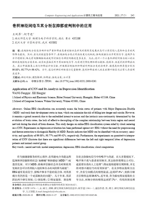
2021575作为脑健康服务的核心部件,在线脑电分类能远程监测和评估脑障碍状态(如癫痫[1]和抑郁症(MDD)[2])而蓬勃发展。
对于MDD,准确评估脑状态并及时跟踪其发展状态可以将其陷入危险和自杀的风险降为最低[3]。
EEG通常是弱信号、强噪声和非平稳的混合体,对其准确分类仍然是一个亟需解决的问题[4]。
几十年来,其活跃在两个研究领域:(1)预处理;(2)特征提取。
预处理旨在去除脑电信号中的噪声与伪逆。
在大多数情况下,噪声和干扰与患者密切相关,其去除即使理论上可行,也需要昂贵的人工处理[5];特征提取能够实现降维,并支持对感兴趣信号的有效探索[6]。
在众多特征提取方法中,共有空间模式的精度最高,达到87.4%[7],矩阵分解方法精度达到86.61%,近年来,作为脑电特征提取的主导方法,时频分析的精度达到87.5%[8]。
传统的预处理卷积神经网络及其分析在抑郁症判别中的应用王凤琴1,柯亨进21.湖北师范大学物理与电子科学学院,湖北黄石4351062.武汉大学计算机学院,武汉435001摘要:在线脑电分类能准确评估严重抑郁症患者的脑状态并及时跟踪其发展状态可以将其陷入危险和自杀的风险降为最低。
然而,在无经验监督条件下,在线脑电分类应用面临更大的挑战:脑电数据往往具有弱信号、高噪声与非平稳特性;缺乏有效解耦脑疾病发作时脑区与神经网路的复杂关系。
为此,设计一个以卷积神经网络为核心的云辅助在线脑电分类系统,该系统直接应用于原始脑电信号,无需进行预处理和特征提取,能精准、快速判别抑郁症状态。
在公开数据集上进行抑郁症评估实验,对健康控制组和抑郁症对照组分类的准确率、敏感度和特异度分别为99.08%、98.77%和99.42%。
另外,通过对神经网络进行定量解释,表明抑郁症病人的左右颞叶脑区与正常人存在明显差异。
关键词:神经网络;模型解释;抑郁症;脑电分类;云计算文献标志码:A中图分类号:TP391doi:10.3778/j.issn.1002-8331.2008-0261Application of CNN and Its Analysis in Depression IdentificationWANG Fengqin1,KE Hengjin21.School of Physics and Electronic Science,Hubei Normal University,Huangshi,Hubei435106,China2.School of Computer Science,Wuhan University,Wuhan435001,ChinaAbstract:Online EEG classification can accurately assess the brain status of patients with Major Depression Disable (MDD)and track their development status in time,which can minimize the risk of falling into danger and suicide.However, it remains a grand research due to the embedded intensive noises and the intrinsic non-stationarity determined by the evolution of brain states,the lack of effective decoupling of the complex relationship between brain region and neural network during the attack of brain diseases.This study designs an online EEG classification system aided by cloud centering on a CNN.Experiments on depression evaluation has been performed against raw EEG without the need for preprocessing and feature extraction to distinguish Healthy&MDD.Results indicate that MDD can be identified with an accuracy,sensi-tivity,and specificity of99.08%,98.77%and99.42%,respectively.Furthermore,the experiments on quantitative interpre-tation of CNN illustrate that there are significant differences between the left and right temporal lobes of depression patients and normal control group.Key words:neural network;model interpretation;depression;EEG classification;cloud computation基金项目:湖北省教育厅科学技术研究计划指导性项目(B2018142)。
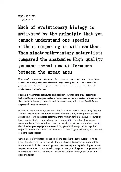
NEWS AND VIEWS13 July 2018Much of evolutionary biology is motivated by the principle that you cannot understand one species without comparing it with another. When nineteenth-century naturalists compared the anatomies High-quality genomes reveal new differences between the great apesHigh-quality genome sequences for some of the great apes have been assembled using state-of-the-art sequencing tools. The assemblies provide an unbiased comparison between humans and their closest evolutionary relatives.Figure 1 | A Sumatran orangutan and her baby. Kronenberg et al.5 assembledhigh-quality genome sequences for a chimpanzee and an orangutan, and compared these with the human genome to look for evolutionary differences.Credit: Fiona Rogers/Minden Pictures/FLPAof humans and other apes, it became clear that these species shared many features and had evolved from a common ancestor. More recently, developments in DNA sequencing — which enabled assembly of the human genome1 in 2001, followed by lower-quality ‘draft’ genomes for other great apes2–4— have transformed our understanding of this evolutionary process. Writing in Science, Kronenberg et al.5 describe new great-ape genome assemblies, generated using a technology that surpasses previous methods. This work marks a new stage in our ability to study and compare these species.Genome assembly is often likened to piecing together a jigsaw puzzle — a huge jigsaw for which the box has been lost and we have only a vague idea of what the whole should look like. The analogy holds because sequencing technologies cannot sequence an entire chromosome in one go. Instead, they fragment the genome into many separate pieces, called reads, which have to be matched, overlapped and placed together.Previous generations of sequencing machines produced reads that were only about a hundred base pairs long, or perhaps a thousand base pairs but at exorbitant cost. Curren t machines such as Pacific BioScience’s single-molecule real-time (PacBio SMRT) sequencer produce reads tens of thousands of base pairs in length. Even with this improvement, hundreds of thousands of reads are needed to span a genome of three billion base pairs such as that of humans, Moreover, in practice, a large excess is used (typically more than 30 genomes’ worth) to mitigate errors and resolve overlap ambiguities. A further complication arises from the fact that genomes are filled with stretches of DNA in which the same pattern is repeated many times, either in series or scattered throughout the genome. In apes, such repetitive DNA comprises a substantial fraction of the genome.Because of these difficulties, the first great-ape genome projects used the human genome as a scaffold to help assemble genomic regions that are structurally similar to those of humans — that is, in which corresponding stretches of DNA lie in the same order and are present in a similar number of copies. This strategy enabled better assembly in such regions. But in regions where genome structure has evolved very differently in humans and other great apes, the great-ape draft assemblies tended to be more fragmented, and the resulting variation in assembly quality effectively constituted a bias towards the human genome. These assemblies provided many evolutionary insights, but there has nonetheless been a deficit in our understanding of the genomic elements that make humans unique.One reason why structural variation is important, particularly on the short evolutionary timescale that separates humans and other great apes, is that it provides a way for genomes to evolve rapidly. When a whole chunk of DNA is removed or duplicated, its molecular function can be inhibited or enhanced in one step, rather than through successive mutations at individual bases. Indeed, much of the great-ape genome seems to be modular in nature, and is therefore susceptible to the kind of building-block alteration that structural variation allows. It is also thought that gene loss is a key mechanism for evolutionary change6,7. This might seem counterintuitive, but genes often act to constrain, rather than promote, a particular function. Disabling them by removing, duplicating or relocating a chunk of DNA might be the simplest way to confer beneficial effects.Kronenberg et al. used PacBio SMRT to assemble high-quality genomes for a chimpanzee and an orangutan, along with two human genomes for comparison (Fig.1). The long reads enabled them to do away with the human-genome scaffold used previously, and to increase the typical distance between gaps by about 100-fold compared with previous assemblies. The authors found about 600,000 structural differences between these genomes and that of humans, including more than17,000 differences specific to humans. Of these, many changes disrupt genes in humans that are not disrupted in other apes. Genes whose activity is suppressed specifically in humans are more likely than other genes to be associated with a human-specific structural variant.Many genes produce multiple versions, called isoforms, of the protein they encode, each of which can have a different role. Kronenberg and colleagues found evidence that one human-specific structural change — a large deletion in the gene FADS2—might have altered the distribution of isoforms the gene produces. These isoforms are involved in the synthesis of fatty acids needed for brain development and immune response8, and are difficult to obtain from a purely herbivorous diet. Correspondingly, FADS2 has been a target for natural selection associated with dietary changes towards or away from animal fats in recent human evolution8. Chimpanzees eat a small amount of meat, so it is not known what (if any)human-specific traits might have resulted from this deletion, but it does suggest that shifting dietary patterns could have been a feature of human evolution over long timescales.Structural variation also seems to have had a role in brain evolution. Human brains are much larger than those of other apes, and it is plausible that genes involved in brain growth and development were key to the evolution of this trait. The authors analysed the sequences of genes that are active in radial glial cells, which are progenitors for neurons and other cells in the brain’s cortex, and compared protein production by these genes in humans and chimpanzees using cortical organoids —3D models of brain tissue grown in vitro. These analyses revealed that 41% of genes whose activity is suppressed in human radial glial cells are associated with a human-specific structural variant. Again, this is consistent with structural genomic changes causing disruption or loss of gene function during great-ape evolution. Intriguing as Kronenberg and colleagues’ findings are, there is also a broader significance to their work. Several groups and consortia are applying new sequencing technologies to different organisms. Ultimately, researchers want accurate,high-resolution assemblies for all species, and to compare these genomes on an equal footing. This will improve evolutionary analyses and reveal complex mutation processes that have hitherto been obscured. Large genome assembly currently remains hugely expensive, and even state-of-the-art sequencing tools struggle to resolve repetitive sequences on scales above a few hundred thousand base pairs, making assembly of certain genomes challenging. But tools to read whole genomes with negligible errors on inexpensive hardware are not far away, and are almost available for small bacterial genomes9.It is clear that we are leaving behind the initial period of evolutionary genomics, in which analy ses involved comparing a genome of interest to a few ‘gold standard’ genomes, such as human, mouse or zebrafish. Instead, we are moving towards a more complete and equable genomic view of life.Nature559, 336-338 (2018)doi: 10.1038/d41586-018-05679-9Nature BriefingSign up for the daily Nature Briefing email newsletterStay up to date with what matters in science and why, handpicked from Nature and other publications worldwide.Sign Up。

DatasheetHP Prime Graphing Calculator Touch-enabled.Full color.Revolutionaryfunctionality.Experience handheld calculating in the age of touch with the HP Prime Graphing Calculator.This full-color, multi-touch calculator has touchscreen or keypad interaction,powerful math applications,formative assessment tools,wireless connectivity1,and a long-life, Li-ion rechargeablebattery.College Board and IB approved.Rest easy with a calculator that’s College Board-approved for use on the PSAT/NMSQT®,SAT®,SAT®Subject Tests in Mathematics,and select AP®Exams;and InternationalBaccalaureate®-approved for use on IB Diploma Programme examinations.So many applications in such a small package.Easily switch between symbolic,graphical,and numerical table views with dedicated buttons.Explore math concepts with Dynamic Geometry,CAS,Advanced Graphing,and spreadsheetapplications.The calculator you’ll want to hold on to.Say hello to the evolution of handheld calculating in a sleek,slim,brushed metal design thatlooks great and performs even better.Keep the calculator protected when it’s not in use withthe slide-on protective cover.Enjoy a feature-rich calculating experience with a familiar HP keypad and l arge3.5-inchdiagonal, multi- touch display.Featuring:●We don’t stop at hardware.You also get an integrated tool suite.HP Equation Writer supports multiple linear andnon-linear equation solving.HP Solve is a time-saving application that allows you to store equations and solve forvariables.●Be productive longer with the lithium-ion rechargeable battery.When you need to charge up,the convertible chargerworks with the USB connection on your PC or a standard AC wall plug.●Create a formative assessment bundle by using the HP Prime Wireless Kit1and HP Connectivity Kit2to wirelesslyconnect an HP Prime Graphing Calculator to a PC and enable teachers to poll students and view their work in real-time.●Turn the calculator into a testing tool with a test-mode configuration that makes only pre-approved functionsavailable.1Compatible only with HP Prime Graphing Calculator SKU G8X92AA.The HP Prime Wireless Kit is sold separately and includes one PC antenna and30wireless modules,with bi-directional transmission range up to15 meters.2The HP Connectivity Kit is included with the HP Prime Graphing Calculator(G8X92AA only).Keypad or touchscreen. You decide.HP Prime Graphing CalculatorPart number G8X92AADisplay320x24016-bit TColor Touch Screen(10lines x33characters+menus+header)Display type TFTEnclosure material PlasticEntry system logic RPN;Algebraic;TextbookMenus/Prompts YesKeyboard AlphanumericBest used for Engineering;Computer science;Surveying;Trigonometry;Statistics;Geometry;Biology;Chemistry;PhysicsGraphing Functions2-D Function,Polar,Parametric Plot;Differential Equation,Bar Plot;Histogram,Scatter Plot;Find:Intersect,Extremum,Slope,Area;Zoom,Trace, Co-ordinates,ShadeMath functions+,-,x,÷,?,1/x,+/-,In,ex,x?y;yx,LOG,10x,x2,%,?,n!;Fractions;Degrees,radians,or grads mode;Trigonometric functions/inverses;Hyperbolics/inverses;HP Solve application(root finder);Numeric Integration;Symbolic Integration;Numeric differentiation;Symbolic differentiation;Complex number of functions;Polynomial root finder,Taylor series;Absolute value,round;Integer,&fractional part of a number;Modulo function,floor,ceiling;CAS systemExpansion features USBMemory256MB flash memoryPower supply Lithium Ion rechargableAuto power off User selectable,default5minutesWeight228g(8.04oz)Dimensions18.23x8.58x1.39cm(7.13x3.38x.55in)Warranty Limited1-year warranty(may vary by region)What's in the box Calculator;Hard Cover;Quick Start Guide;CD(connectivity software and User Guide);USB cable;USB power supplyThe product could differ from the images shown. © 2015 Hewlett-Packard Development Company, L.P. The information contained herein is subject to changewithout notice. Specific features may vary from model to model. The only warranties for HP products and services are set forth in the express warranty statements accompanying such products and services. Nothing herein should be construed as constituting an additional warranty. HP shall not be liable for technical oreditorial errors or omissions contained herein.Learn more at 4AA5-9099ENUS, June 2015。

英国文化复习题1) 请大家结合所发材料及上课内容把这些习题所在的知识点掌握;不要去死记硬背,尤其不要把答案带到考场,被抓到舞弊,后果自己负责;2) 简答题希望同学们自己去看材料并做出总结,不要背别人写好的,如果两位同学考试时答案完全一致,都不能得到该题分数。
写得不好无所谓,我最看重的是大家良好的学习态度;3) 古希腊一章主要涉及的是哲学和戏剧这部分,这里我没有给复习题,希望大家自己再去看看所发材料;4) 基督教这章我们不做要求;5) 希望大家结合复习题,再认真阅读本学期《英国文化》所学知识,毕竟我们学习不是完全为了考试;I. Decide whether the following statements are true or false:1. Britain is no longer an imperial country. T2. The Commonwealth of Nations include all European countries. F3. 1 in 10 of the British population are of non-European ethnicity. F4. The stereotype of the English gentleman never applied the majority of the British people. T5. Great Britain includes 3 constituent countries: England, Scotland, and Wales. F6. Northern Ireland is part of Great Britain. F7. When people outside UK talk about England, they mistake it as Britain sometimes. T8. The Scots and Welsh have a strong sense of being British. F9. Scotland was never conquered by the Romans. T10. Most people in Scotland speak the old Celtic language, called "Gaelic". F11. Scotland was unified with England through peaceful means. T12. Wales is rich in coal deposits. T13. Cardiff, the capital of Wales, is a large city. F14. The title of Prince of Wales is held by a Welsh according to tradition. F15. Ireland is part of Great Britain. F16. "Ulster", referring to Northern Ireland, was once an ancient Irish kingdom. T17. The capital of Belfast is a large city with half a million people. F18. Northern Ireland is significant because of its manufacturing industry. F19. The majority of Irish people were descendants of the original Celtic people who inhabited the British Isles before the Romans arrived 2000 years ago. T20. Most British people are Protestants while most Irish people are Catholics. T21. The British government does not have direct rule from London over Northern Ireland. F22. Sinn Fein is a legal political party in Northern Ireland. T23. It is no doubt that Britain is the oldest representative democracy in the world. F24. In Britain, the process of state-building has been one of evolution rather than revolution, in contrast to France and the U.S. T25. The oldest institution of government according to the text is the Monarchy. T26. The divine right of kings means the sovereign derived his authority from his subjects. F27. While the King in theory had God on his side, it was thought that he should exercise absolute power. F28. The term "parliament" was first officially used in 1066 to describe the gathering of feudal barons and representatives from counties and towns. F 29. Britain is both a parliamentary democracy and a constitutional monarchy. T30. Britain, like Israel, has a written constitutions of the sort which most countries have. F31. Common laws are laws which have been established through common practice in the courts.T32. In the U.K., a government cannot stand for longer than five years except in exceptional circumstances. T33. The parliament can call an election sooner than five years. F34. Anyone who is eligible to vote with 500 pounds as deposit can stand as an MP. T35. Each main party is given some time on national TV to "sell" their policies. The time is not given free and has to be paid by the party. F36. The amount spent in national campaign is not limited other than that on TV. T37. The campaigns are not simply about telling people how good your policies are, but also about telling them how bad your opponents are. T38. Secrecy is not an important part of the voting process. F39. The counting of votes run over a period of a few days. F40. There are two major national parties in the U.K. according to the text. F41. Liberal Democratic Party is the newest of the major national parties. F42. By the 1880's the British economy was dominant in the world. T43. Both the U.S. and Canada overtook Britain in economy by 1900. F44. In World War II, Britain had gone heavily into debt in order to develop its manufacturing industry and borrowed large amounts from the U.S. and France. F45. Another reason for British decline is the loss of its colonies, especially India, which gained its independence in 1947. T46. In the 1970's, with the souring price of oil and high rates of inflation, Britain went through a bad period. In 1979, the Labour Party had to step down from the government. T47. The leader of the Conservatives, Margaret Thatcher started a series of reforms. An extensive programme of privatization was carried out but she did not succeed in saving the British economy.F48. Tertiary industries include banking, insurance, tourism, agriculture and the selling of goods.F49. Britain has a large sector of agriculture producing 11.6% of its national wealth. F50. According to the text, the tertiary industry produces approximately 2/3 of the national wealth. T51. The service industry in the U.K. employs 70% of the total work force. T52. The purpose of British education is not only to provide children with literacy and other basic skills but also to socialize children. T53. The state seldom interferes with the decision of when, where, how and what children are taught. F54. The enduring feature of British education is the continuing debate over what should be taught in school and universities. F55. The 1944 Education Act made entry to secondary schools and universities "meritocratic".T56. The public schools are part of the national education system and funded by the government.F57. British universities are public bodies which receive funds from central government. T58. In Oxford and Cambridge the BA converts to an MA several years later, upon payment of a fee. TII. Choose the correct answer to each of the following.1.__________ is not considered a characteristic of London. (a) The cultural centre (b) The business centre (c) The financial centre (d) The sports centre2. ________________ is not true about the characteristics of Britain.(a) Economic differences between north and south(b) Differences of social systems between Scotland and Wales(c) Class differences between a white-collar worker and a blue-collar worker(d) Cultural differences between immigrants and the British3. _______________ can not be found in London. (a) Teahouses (b) Galleries (c) Museums (d) Theatres4. Which of the following is not true about Britain? (a) It used to be an imperial country in the world. (b) It plays an active role as a member of European Union. (c) It is a relatively wealthy and developed country. (d) It used to be one of the superpowers in the world.5. Three of the following are characteristics of London. Which of the four is the exception?(a) London is a political, economic and cultural centre of the country.(b) London has a larger population than all other cities in England.(c) London is not only the largest city in Britain, but also the largest in theworld.(d) London has played a significant role in the economic construction of the country.6. The Tower of London, a historical sight, located in the centre of London, was built by___________.(a) King Harold(b) Robin Hood(c) Oliver Cromwell(d) William the Conqueror7.________ were the ancestors of the English and the founders of England. (a) The Anglo-Saxons (b) The Normans (c) The Vikings (d) The Romans8. __________ is the largest city in Scotland. (a) Cardiff (b) Edinburgh (c) Glasgow (d) Manchester9. Why did the Scottish Kings decide to form an independent singular Scottish state in the ninth century?(a) They needed a unified independent nation to fight against Viking raids.(b) They felt it necessary to develop their own industry.(c) They were threatened by the Anglo-Saxons' invasion.(d) They had to do it in order to resist the English.10. Where do the majority of people in Scotland live? (a) In the Highlands. (b) In the Lowlands. (c) In the Uplands. (d) In the west of Scotland.11. Which of the following statements is not true? (a) Wales was invaded by the Romans. (b) Wales was occupied by the Anglo-Saxons. (c) Wales was conquered by the Normans. (d) Wales was threatened by the English.12. Which of the following parties in Scotland still wants an independent Scotland?(a) The Labour Party.(b) The Liberal Party.(c) The Scottish Nationalist Party.(d) The Conservative Party.13. Scotland joined the Union by agreement of the English and Scottish parliaments ________.(a) In 1715(b) In 1688(c) In 1745(d) In 170714. Llywelgn ap Gruffudd is more than a simple historical figure for the Welsh. He is almost considered the legendary hero of Welsh nationalism because___________.(a) he became the first Prince of Wales in 1267(b) he brought the English under his control(c) he led a historic uprising against the English(d) he unified Wales as an independent nation15. In the seventeenth century, the English government encouraged people from Scotland and Northern England to emigrate to the north of Ireland, because___________.(a) they wanted to increase its control over Ireland(b) they had too many people and didn't have enough space for them to live in(c) they intended to expand their investment(d) they believed that Ireland was the best place for them16. In 1969, the first British soldiers were seen on Northern Ireland Street. They came first___________.(a) to maintain traffic order in Northern Ireland(b) to protect the Catholic people(c) to protect the Protestant people(d) to replace the Royal Ulster Constabulary since they were unable to keep social order17. Northern Ireland is the smallest of the four nations, but is quite well-known in the world for___________.(a) its most famous landmark, the "Giant's Causeway"(b) its rich cultural life(c) its low living standards(d) its endless political problems18. Faced with conflicting demands the British government chose a compromise and organised a partition of Ireland, because___________. (a) the British government wouldn't be able to control Ireland any longer by force(b) the British government intended to satisfy both sides─Catholics as well as Protestants(c) Catholics in Ireland demanded a partition of Ireland(d) Protestants welcomed the idea of partition19. Which of the following statements is not true?(a) Sinn Fein is the legal political Party in Northern Ireland.(b) Those who want to unite Northern Ireland with Britain are called Unionists.(c) Social Democratic and Labour Party is a very important political Party in Britain.(d) Those who show their loyalty to the British Crown are called Loyalists.20. In the early 1970s, the IRA___________.(a) killed many Protestants and Catholics(b) burned down the houses of Catholics(c) murdered individuals at random(d) carried out a series of bombing and shooting and attacked the security forces as their main target21. 1972 was the worst year of the political troubles in Northern Ireland, because___________.(a) 13 Catholics were shot dead by the police(b) 468 people were killed in Northern Ireland(c) the government carried out a policy known as "internment"(d) Bloody killing of 468 people fortified Catholic opposition to the British presence in Northern Ireland22. Why did the British government decide to replace the Power-Sharing policy with "direct-rule" from London?(a) The Power-Sharing policy was not accepted by the majority of Protestants.(b) The Northern Irish Parliament could not govern the province effectively.(c) The Power-Sharing policy couldn't be carried out.(d) All the above.23. Which of the following statements is not true?(a) In 1981, some convicted IRA prisoners went on a hunger-strike.(b) They demanded for the status of being "political prisoners" by starving themselves.(c) Margaret Thatcher's government gave in to their political demand.(d) The death of prisoners revitalized the political movement of Sinn Fein.24. How many counties do you know there are in Northern Ireland? (a) 26. (b) 6. (c) 32. (d) 20.25. Which of the following is not characteristic of British government? (a) It offers the Queen high political status and supreme power. (b) It is both a parliamentary democracy and a constitutional monarchy. (c) It is the oldest representative democracy in the world. (d) It has no written form of Constitution.26. Which of the following king was executed in the civil war? (a) James I. (b) James II. (c) Charles I. (d) Charles II.27. What happened in 1215? (a) It was the year of Norman Conquest in British history. (b) Forced by barons, King John signed the Magna Carta. (c) Henry IV granted the Commons the power to review money grants. (d) King Egbert united England under his rule.28. Which of the following is not true about the Great Council? (a) They included barons and representatives from counties and towns. (b) They were sometimes summoned by the kings to contribute money. (c) They later developed into what we now know as the Cabinet. (d) They represented the aristocrats as well as the communities.29. Under whose reign was the Bill of Rights passed? (a) James II. (b) William of Orange. (c) Oliver Cromwell. (d) George I.30. Which of the following is not true about the Constitution?(a) It is a document which lists out the basic principles for government.(b) It is the foundation of British governance today.(c) Conventions and Laws passed by Parliament are part of the Constitution.(d) The common laws are part of the Constitution.31. Which of the following about the Parliament is not true? (a) There are no legal restraints upon Parliament. (b) Strictly speaking, the Queen is part of the Parliament. (c) Parliament has the supreme power of passing laws. (d) Parliament has no power to change the terms of the Constitution.32. Which of the following about the Queen is not true? (a) The Queen selects the Prime Minister and the Cabinet. (b) The Queen symbolises the tradition and unity of the British state. (c) The Queen acts as a confidante to the Prime Minister. (d) The Queen is the temporal head of the Church of England.33. Which of the following about the House of Lords is not true? (a) Lords do not receive salaries and many do not attend Parliament sittings. (b) It consists of the Lords Spiritual and the Lords Temporal. (c) The lords are expected to represent the interests of the public. (d) Most of the lords in the House of Lords are males.34. Which of the following about the House of Commons is not true? (a) Members of Parliament elect the Prime Minister and the Cabinet. (b) MPs receive salaries and some other allowances. (c) MPs are expected to represent the interests of the public. (d) Most MPs belong to the major political parties.35. Which group of people can not vote in the general election? (a) Members in the House of Commons. (b) Lords in the House of Lords. (c) The UK citizens above the age of 18. (d) The UK resident citizens of the Irish Republic.36. By whom is a "vote of no confidence" decided? (a) The House of Commons. (b) The House of Lords. (c) The two major parties. (d) The Prime Minister.37. Which of the following is not true about the electoral campaigns?(a) Big parties can buy time to broadcast their policies on the television.(b) There is a limit on the amount of money candidates can spend in theirconstituency campaign.(c) Candidates and their supporters go door-to-door persuading voters to vote for them.(d) Candidates criticize each other's policies to show how good their own policies are.38. How many seats in the House of Commons should a party hold at least in order to win the election?(a) 651.(b) 326.(c) 626.(d) 351.39. Which of the following party adopts a "fatherly" sense of obligation to the poorer people in the society?(a) The Conservative party.(b) The Liberal Democrats.(c) The Party of Wales.(d) The Labour party.40. Which of the following description about the Conservative party is not true? (a) It has been in power for an unusually long period of time. (b) It prefers policies that protect individual's rights. (c) It receives a lot of the funding from big companies. (d) It is known as a party of high taxation levels.41. Which government lost a vote of no confidence and was forced to resign in 1979?(a) The Conservative government.(b) The Liberal government.(c) The Labour government.(d) The radical government.42. Which period of time in British history was described as "private affluence and public squalor"?(a) The 1940s.(b) The 1970s.(c) The 1980s.(d) The 1990s.43. Which of the following about the "poll tax" is not true? (a) It was introduced by the Conservative government. (b) It was introduced by the Labour government. (c) It was an attempt to change local government taxes. (d) It was criticized by many citizens.44. Who is the leader of the Labour party at present? (a) John Major. (b) Tony Blair. (c) Harold Wilson. (d) Margaret Thatcher. 45. Which of the following statements about the UK economy is not true?(a) Britain remains one of the Group of Seven large industrial economies.(b) Britain has experienced a relative economic decline since 1945.(c) There has been a period of steady decreasing of living standards.(d) Some smaller economies have overtaken the UK in terms of output per capita.Answer:46. Which of the following was not the reason for the relative economic decline since 1945?(a) Britain did not invest in modern equipment and new products.(b) Britain spent a high proportion of its national wealth on the military.(c) Britain had been heavily in debt to finance the war.(d) Britain had carried out the nationalisation of the businesses.47. Which of the following livestock has the biggest number in the UK? (a) Beef cattle. (b) Dairy cattle. (c) Chicken. (d) Sheep.48. Where is the best agricultural land in Britain? (a) In the southeast of England. (b) In the northeast of England. (c) In the southeast of Scotland. (d) In the northeast of Scotland.49. Which of the following is not a company in the energy sector? (a) Shell. (b) ICI. (c) RTZ. (d) British Gas.50. Which of the following used to be the last independent car company inthe UK?(a) Ford.(b) Peugeot.(c) Rover.(d) BMW.51. In aerospace industry, which two countries are ahead of Britain? (a) The U.S. and Germany. (b) The U.S. and Russia. (c) Germany and Russia. (d) France and Russia.52. Which civil airline was started in 1924 after the First World War? (a) Imperial Airways. (b) British Airways. (c) Hawker-Siddeley Aviation. (d) The British Aircraft Corporation.53. What did Frank Whittle do in 1937? (a) He invented the first jet plane. (b) He developed the first jet engine. (c) He made the first powered flight. (d) He made the trans-Atlantic flight.54. Which company became an important aero-engine manufacturer after WWI? (a) Boeing. (b) Rolls Royce. (c) McDonnel-Douglas. (d) Hawker-Siddeley Aviation.55. British Aerospace was the merger of which two companies? (a) The British Aircraft Corporation and Hawker-Siddeley Aviation. (b) The British Aircraft Corporation and Rolls Royce. (c) Hawker-Siddeley Aviation and GEC Avionics. (d) Hawker-Siddeley Aviation and Rolls Royce.56. In Britain, the great majority of parents send their children to___________. (a) private schools (b) independent schools (c) state schools (d) public schools57. In Britain, children from the age of 5 to 16___________. (a) can legally receive partly free education (b) can legally receive completely free education (c) can not receive free education at all (d) can not receive free education if their parents are rich58. If a student wants to go to university in Britain, he will take the examination called___________.(a) General Certificate of Education—Advanced(b) General Certificate of Secondary Education(c) the common entrance examination(d) General National Vocational Qualifications59. _____________ is a privately funded university in Britain. (a) The University of Cambridge (b) The University of Oxford (c) The University of Edinburgh (d) The University of Buckingham60. Which of the following is not true?(a) Parents send their children to public schools because they are rich.(b) Parents send their children to public schools because their children can get better jobs when they leave school.(c) Parents send their children to public schools because their children can have a better chance of getting into a good university.(d) Parents send their children to public schools because their children prefer to go to public schools.61. Which of the following is not a characteristic of the Open University? (a) It's open to everybody. (b) It requires no formal educational qualifications. (c) No university degree is awarded. (d) University courses are followed through TV, radio, correspondence, ect.62. In the examination called "the 11 plus", students with academic potential go to ___________.(a) grammar schools(b) comprehensive schools(c) public schools(d) technical schools63. Which of the following is not included in the National Curriculum?(a) Children must study the subjects like English, mathematics, science and so on.(b) Children must sit in A-level exams.(c) Children must pass national tests.(d) Teachers must teach what they are told.64. Which of the following is not true about the British education system? (a) It's run by the state. (b) It's funded by the state. (c) It's supervised by the state. (d) It's dominated by the state.65. _________________ would admit children without reference to their academic abilities.(a) Comprehensive schools(b) Secondary schools(c) Independent schools(d) Grammar schoolsⅢ.Topics for Discussion1. What was the British Empire? What do you know about it? In what way is the Empire still felt in Britain and in the international field?2. Why does the author say that it is not possible to sum up the British people with a few simple phrases?3. "British history has been a history of invasion". Please illustrate this point with the examples from the text. How did each of the invasions influence English culture ?2. What are some general characteristics of Scotland? How did Scotland become part of the union of Great Britain?4. Describe characteristics of Wales and Wales' unification with Great Britain.5. Are there any differences between England, Scotland and Wales in terms of cultural tradition ?6. Why is Northern Ireland, according to the author, so significant in the United Kingdom? What is the political problem there?7. What are some of the factors in Irish and English history that affect the situation in Northern Ireland today?8. Different parties and groups in the United Kingdom have differentsolutions to the political problem in Northern Ireland. Please sum up their different attitudes.9. Has the author offered a solution to the political problem in Northern Ireland?10. What are some of the characteristics of the British constitutional monarchy? How has the English monarchy evolved gradually to the present constitutional monarchy?11. How did the doctrine of the "divine right of kings", according to the author, lead to the English Civil War? What do you know about the causes of the English Revolution in the 17th century?12. What is the history of English parliament? What role did the parliament play in the Civil War?13. Discuss the major characteristics and the main content of the British constitution.14. Why does the author say that parliament is supreme in the British state? What functions does parliament have? What role does the Queen ( King ) and the Prime Minister play in British government?15. What kind of institution is the House of Lords? What role does it play in British government?16. Who can stand for election as an MP in the UK? Why are small parties and independent candidates powerless in the election campaign for the formation of a government?17. What are the three big parties in the UK? What are some of the similarities and dissimilarities between the three parties?18. What are some of the recent political trends in the UK? Are these trends more democratic or undemocratic? What is the author's opinion?19. The author says that John Major's conservatives remain unpopular in 1997. What reasons does the author give for this political situation?20. Please define "absolute decline and relative decline" in the UK economy. How does the author explain the reasons for the absolute decline and relative decline?21. What did the Conservative Party under Mrs. Margaret Thatcher promise to do to the UK national economy in 1979? The word "reform" in the national economy was also popular when Mrs. Margaret Thatcher formed the government and decided to change the UK economy. What was her radical reform program? Was the program successful according to the author?22. What are the three main areas in national economies? Describe thedevelopment of each of the three areas in the UK economy.23. The author believes that Britain, like most developed economics, has seena relatively shrinking of the importance of secondary industry and a spectacular growth in tertiary or service industries. Why is it so? Do you see a similar growth in tertiary industries in China in the past 20 years? How is this growth related to the reform and opening up to the outside world?24. What are the purposes of the British education system? Please comment on these purposes. What are the main purposes of the Chinese education system? Are there any differences or similarities in the education of the two nations?25. How does the British education system reflect social class?26. What are the major changes that have taken place since World War II? Is British education moving towards more progress or more equality? Pick up some examples from the text to illustrate your points.27. Why does the author say that universities in Britain have been rather elitist?28. What is the Open University in Britain? What do you think of this system?。

QUIZ 1Decide whether the following statements are True (T) or False (F) : (1*10=10)1.Britain is no longer an imperial country. _____2.The Commonwealth of Nations includes all European countries. ____3.When people outside the UK talk about England, they mistake it as Britain sometimes.______4.Scotland was never conquered by the Romans. _____5.Scotland was unified with England through peaceful means.______6.Ireland is part of Great Britain. _______7.“Ulster”, referring to Northern Ireland, was once an ancient Irish Kingdom.____8.Most British people are Protestants while most Irish people are Catholics.____9.The Good Friday Agreement was approved on 10 April 1998. _____10.Northern Ireland today is governed by separate jurisdictions: that of Republic of Ireland and thatof Great Britain.______Multiple choices and filling blanks: (1*20=20)1.Which of following is NOT considered a characteristic of London?A. The cultural centerB. The business centerC. The financial centerD. The sports center2. Which of the following is NOT true about the characteristics of Britain?A. Economic difference between north and south.B. Differences of social systems between Scotland and Wales.C. Class differences between a white-collar worker and a blue-collar worker.D. Cultural differences between immigrants and British.3. Who were the ancestors of the English and the founders of England?A. The Anglo-Saxons.B. The Normans.C. The Vikings.D. The Romans.4. Which is the largest city in Scotland?A. Cardiff.B. Edinburgh.C. Glasgow.D. Manchester.5. Where do the majority of people in Scotland live?A. In the Highlands.B. In the lowlands.C. In the Uplands.D. In the west of Scotland.6. Which of the following statement is NOT true?A. Wales was invaded by the Romans.B. Wales was occupied by the Anglo-Saxons.C. Wales was conquered by the Normans.D. Wales was threatened by the English.7. When did Scotland join the Union by agreement of the English and Scottish parliaments?A. In 1715.B. In 1688.C. In 1745.D. In 1707.8. Llywelyn ap Gruffudd is not a simple historical figure for the Welsh. He is almost considered the legendary hero of Welsh nationalism because _____A. he became the first Prince of Wales in 1267B. he brought the English under his controlC. he led a historic uprising against EnglishEngland to emigrate to the north of Ireland, because____A. they wanted to increase its control over thereB. they had too many people and did not have enough space for them to livein BritainC. they intended to expand their investmentD. they believed that Ireland was the best place for them10. Northern Ireland is the smallest of the four nations, but is quite known in the world for_____A. its most famous landmark, the “Giant’s Causeway”B. its rich cultural lifeC. its low living standardsD. its endless political problems11. Faced with conflicting demands the British government chose a compromise and organize a partition of Ireland in 1921, because_____A. the British government wouldn’t be able to control Ireland any longer by forceB. the British government intended to satisfy both sides—Catholics and ProtestantsC. Catholics in Ireland demanded a partition of IrelandD. Protestants welcomed the idea of partition12. In the early 1970s, the IRA _____A. killed many protestants and CatholicsB. burned down the house of CatholicsC. murdered individuals at randomD. carried out a series of bombing and shooting and attacked the security forces as their main target13. 1972 was the worst year of the political troubles in Northern Ireland, because____A. 13 Catholics were shot dead by the policeB. 468 people were killed in Northern IrelandC. bloody killing of 468 people fortified Catholic opposition to the British presence in Northern IrelandD. the government carried out a policy known as “internment”14. Why did the British government decide to replace the power-sharing policy with “direct-rule” from London>A. the Power-sharing policy was not accepted by the majority of ProtestantsB. the Northern Irish Parliament could not govern the power effectivelyC. the power-sharing policy couldn’t be carried out.D. all the above15. Which of the following statements is NOT true?A. in 1981, some convicted IRA prisoners went on a hunger-strike.B. they demanded for the status of being “political prisoners” by starving themselvesC. Margaret Thatcher’s government gave in to their political demands.D. the death of prisoners revitalized the political movement of Sinn Fein.16. How many countries are there in Northern Ireland?A. 26.B. 6.C.32D. 2017. Which of the following agreement is accepted by both Catholics and Protestants in Northern Ireland?A. the Anglo-Irish Agreement.D. the Multi-party Agreement.18. According to the Good Friday Agreement, Northern Ireland today should be governed by the following jurisdiction except_____A. the jurisdiction of the Republic of IrelandB. the jurisdiction of loyalist ministersC. the jurisdiction of Great BritainD. the jurisdiction of Northern Ireland19. The full name of the United Kingdom is the ____________________________ and _______________________________.20. The island of Great Britain is made up of England,________________ and _____________.21. The United Kingdom has been a member of the ____________________ since 1973.22. Britain is a country with a history of invasion. In 43 AD Britain was invaded by __________.23. Charles the First, king of Britain, was executed, because he attempted to overthrow __________ in the English Revolution.24. The battle of Bannockburn led by Robert the Bruce succeeded in winning the full independence of __________25. To pursue Irish independence, the most spectacular event in the Irish history was ________ of 1916, in which the rebels occupied Dublin’s _________and forced the British to take it back by military means.26. The Good Friday Agreement assures _________ that Northern Ireland “remain part of the United Kingdom and shall not cease to be so without __________ of Northern Ireland.”Tell what you know about the following in your own words;(5*2=10)1.London2.Home RuleQUIZ 2Decide whether the following statements are True (T) or False (F) : (1*10=10)11.In Britain, the process of state-building has been one of evolution rather than revolution, incontrast to France and the US . _____12.The oldest institution of government in Britain is the Monarchy. ____13.The term “parliament” was officially used in 1066 to describe the gathering of feudal barons andrepresentatives from countries and town.______14.Britain is both a parliamentary democracy and a constitutional monarchy. _____15.Britain is both a parliamentary democracy and a constitutional monarchy .______16.Britain, like Israel, has a written constitution of the sort which most countries have. _______mon laws are laws which have been established through common practice in the courts.____18.Anyone who is eligible to vote with 500 pounds as deposit can stand as an MP . ____19.Each main party is given some time on national TV to “sell” their policies. Th e time is not givenfree and has to be paid by the party. _____20.Secrecy is not an important part of the voting process. ______Multiple choices and filling blanks: (1*20=20)2.Which of following is NOT a characteristic of British government ?A. It offers the Queen high political status and supreme power.B. It is both a parliamentary democracy and a constitutional monarchy.C. It is the oldest representative democracy.D. It has no written form of constitution.2. Which of the following king was executed in the civil war?A. James I .B. James II.C. Charles I.D. Charles II3. Under whose reign was the Bill of Rights passed?A. James II.B. William of Orange .C. Oliver Cromwell.D. George I .4. Which of the following is NOT related to the Constitution?A. It is a written document which lists out the basic principles for government.B. It is the foundation of British government today.C. Conventions and laws passed by parliament are part of the Constitution.D. The common laws are part of the Constitution.5. Which of the following is NOT a true description of the Queen’s role?A. The Queen selects the Prime Minister and the Cabinet.B. The Queen symbolizes the tradition and unity of the British state.C. The Queen acts as a confidante to the Prime Minister.D. The Queen is the temporal head of the Church of England.6. Which of the following is NOT a feature of the House of Lords?A. Lords do not receive salaries and many do not attend Parliament sittings.B. It consists of the Lords Spiritual and the Lords Temporal.C. The lords are expected to represent the interests of the public.D. Most of the lords in the House of Lords are males.7. By whom is a “vote of no confidence” decided?A. The House of Commons.B. The House of Lords.A. they are not from the aristocratic families.B. they cannot sit in the House of Lords.C. they earned their titles through their outstanding achievement.D. the titles cannot be inherited by their children.9. Which of the following is Not true about the electoral campaign?A. Big parties can buy time to broadcast their policies on the television.B. There is a limit on the amount of money candidates can spend in the constituency campaign.C. Candidates and their supporters go door-to-door persuading voters to vote for them.D. Candidates criticize each other’s policies to show how good their own policies are.10. Which of the following statements is NOT correct?A. There are no legal restraints upon Parliament.B. Strictly speaking, the Queen is part of the Parliament.C. Parliament has the supreme power of passing law.D. Parliament has no power to change the terms of the Constitution.11. ____________________________, the ancestor of the present Queen, Elizabeth II, united England under his rule in 829.20. The island of Great Britain is made up of England,________________ and _____________.21. The United Kingdom has been a member of the ____________________ since 1973.22. Britain is a country with a history of invasion. In 43 AD Britain was invaded by __________.23. Charles the First, king of Britain, was executed, because he attempted to overthrow __________ in the English Revolution.24. The battle of Bannockburn led by Robert the Bruce succeeded in winning the full independence of __________25. To pursue Irish independence, the most spectacular event in the Irish history was ________ of 1916, in which the rebels occupied Dublin’s _________and forced the British to take it back by military means.26. The Good Friday Agreement assures _________ that Northern Ireland “remain part of the United Kingdom and shall not cease to be so without __________ of Northern Ireland.”Tell what you know about the following in your own words;(5*2=10)3.London4.Home Rule21.By the 1880’s, the British economy was dominant in the world. _____22.By the end of WWII, Britain has gone heavily into debt in order to develop manufacturing industryand borrowed large amounts from the US and France. ____23.As a member of the WTO, the UK is playing a very important role in the world trade.______24.Tertiary industries include banking, insurance, tourism, agriculture and the selling of goods. _____25.The 1944 Education Act made entry to secondary and universities “meritocratic” .______26.Public schools are part of the national education system and funded by the government. _______27.British universities are public bodies which receive funds from central government.____28.All secondary schools in Britain are run and supervised by the government. ____29.Grammar schools select children at the age of 11 and provide them with general education. _____30.The state seldom interferes with the decision of when, where, how and what children should betaught . ______Multiple choices and filling blanks: (1*5=5)3.In Britain, children from the age of 5 to 16__________ ?A. can legally receive partly free education.B. can legally receive completely free education.C. can not receive free education at all.D. can not receive free education if their parents are rich.2. In Britain, the great majority of parents send their children to ____?A. private school .B. independent school.C. state school.D. public school3. In the exam called “the 11-plus”, students with academic potential go to___?A. grammar school.B. comprehensive school .C. public school.D. technical school.4. Which of the following is a privately funded university in Britain?A. Cambridge .B. Oxford.C. Edinburgh.D. Buckingham.5. Which of the following is NOT a company in the energy sector?A. Shell.B. ICI.C. RTZ.D. British Gas.Tell what you know about the following in your own words;(5*3=15)1. The purpose of the British education system2. The important role of British media.3. The decline of UK’s economy31.The origin of Bowling lies in the victory celebration ceremony by the ancient warriors. _____32.Tennis is usually regarded as a winter and spring sport. ____33.The game of golf was invented by the Scottish.______34.The animal-lovers’ groups would like to have horse racing banned. _____35.It is commonly believed that Boxing Day involves the sport of boxing.______36.The biggest Bonfire Night celebration is held in London. _______37.The British media play an important role in shaping a national culture.____38.The Advertising Code ensures that ads are legal, decent, honest and truthful; have a sense ofresponsibility for consumers and society; and respect the principles of fair competition.____39.It is incorrect to say that class and educational differences are reflected in the newspapers peopleread. _____40.The Telegraph readers, for example, will be soft on crime, be quite feminist and interested in greenpolitics .______41.The tabloids are smaller format newspaper with color photos and catchy headlines. They are oftencalled “Gutter Press”.42.When the WWII ended, Britain no longer was the largest military power in Western Europe.______43.The Prime Minister and Cabinet decide on the general direction of Britain’s foreign policy._____44.There are about 60 members of the Commonwealth.______45.Britain is not a member of NATO due to its disagreement with some European countries ondefence policy._______Multiple choices and filling blanks: (1*21=21)4.Which of following about BBC is NOT true?A. There is no advertising on any of the BBC programs.B. The BBC is founded by license fees paid by people who posses TV sets.C. The BBC has four channels.D. The BBC provides the World Service throughout the world.2. A free press is considered very important to the functioning of parliamentary democracy because ______?A. It plays a watchdog function, keeping an eye on the government.B. It informs people of current affairs in the world.C. It provides people with subjective reports.D. It publishes short pamphlets for Parliament.3. Which of the following is the world’s oldest national newspaper?A. The Times.B. The Guardian.C. The Observer.D. The Financial Times.4. Which of the following is British oldest daily newspaper?A. The Telegraph.B. The News of the World.C. The Guardian.D. The Times.5. Which of the following sports was NOT mentioned in Britain?A. Football.B. Tennis.C. Basketball.D. Cricket.6. Which of the following about the tabloid is NOT true?C. They mainly deal in Scandals and gossip about famous people.D. They carry stories with color photos and catchy headlines.7. Where are international tennis championships held?A. Wembley.B. Wimbledon.C. London.D. Edinburgh.8. Which of the following is truly a sport of the royal family ?A. Cricket.B. Skiing.C. Golfing.D. Horsing Racing9. Which of the following is NOT particularly British Christmas tradition?A. enjoying the PantomimeB. the Queen Broadcasting her Christmas messageC. eating chocolate eggs on Easter DayD. shopping on the Boxing Day10. Easter commemorates_____A. the birth of Jesus ChristB. the Crucifixion of Jesus ChristC. the coming of SpringD. the Crucifixion and Resurrection of Jesus Christ11. Which community observes the traditional Ramadan?A. HinduB. SikhC. JewishD. Muslim12. Which celebration particularly happens on the Queen’s birthday?A. BonfireB. The Orange MarchC. Trooping the ColorD. Masquerades13. Which of the following commemorates the Battle of Boyne?A. The Bonfire Night celebration in LewesB. Trooping the color in LondonC. The Eisteddfod in WalesD. The Orange March in Northern Ireland14. Of which people is Robert Burns a national poet?A. the Welsh peopleB. the Irish peopleC. the Scottish peopleD. the English people15. Which countries are the permanent members of the UN Security Council?A. France, China, Germany, Russia and Britain.B. the US, France, Britain, Germany and RussiaC. China, Russia, France, Britain and the US.D. China, Britain, France, the US and Japan.16. On which say is Halloween celebrated?A. October 31st.B. November 5th .C. March 17thD. December 25th17. How much of the globe did Britain rule in its imperial prime?A. 1/4 .B. 1/5C. 1/3D. 2/318. Which of the following is not involved in making the British Foreign Policy?A. the Queen of BritainB. the Foreign and Commonwealth OfficeC. the Prime Minister and the CabinetD. the Ministry of Defense and the TreasuryC. the UN, the EU, NATO, etc.D. a European federal government20. Three of the following factors have contributed to Britain’s special relationship with the United States to a certain degree, which is the exception?A. Britain and the US share the general ideas in many respectsB. They have common interests in every respect.C. They agree generally on how the world economy should be managedD. They have special links in culture.21. Why does Britain have its nuclear naval force?A. Because it is one of the developed countries in the worldB. Because it is a traditional sea power.C. Because it has an advanced industryD. Because it is able to produce submarines.22. When the WWII was over, Britain was active in setting up the UN and became one of the ____________________________ permanent members of _______________________________.20. The present foreign policy of Britain is greatly influenced by its________________ history and also by its _____________.21. The general direction of Britain’s foreign policy is decided by ____________________ and _______________.22. The ______________ newspaper carry more serious and in-depth articles of particular political and social importance.23. _____________ is regarded as the most left-wing newspaper in Britain.24. The battle of Bannockburn led by Robert the Bruce succeeded in winning the full independence of __________25. The BBC stands for ____________________________________.26. The FA stands for ________________________________.27. Phrases like “on a sticky wicket” and “playing with a straight bat” are associated with the sport of_______________.26. There are two kinds of horse racing: flat racing and _________________.”27. People usually dress up and show off their fashionable clothes and elaborate hats for the social event called________________.28. Compared with football, _______________ is a more gentle sport which owes its origin to the church.29. Traditionally, people gave Christmas gifts and money to their staff or servants on __________________, which is the day after Christmas.30. Many Muslims in Britain observe a traditional Islamic festival called ______________ which nothing can be eaten or drunk between dawn and nightfall.Tell what you know about the following in your own words;(3’+4’)5.The foundation of British foreign policy6.The three traditions of Christmas in BritainThe three traditions of Christmas in Britain1.Christmas Pantomime2.Hearing the Queen give her Christmas message to her realm over television and radio3.Boxing day for shoppingThe important role of British mediaIn British political system: inform the population about problems the country maybe facing and what the government is doing to solve such problem.In engendering a national culture: people from different field all share the same experience, they could discuss what they had read or seen. British are all part of the British culture.The foundations of British foreign policyThe contemporary foreign policy of the UK is greatly influenced by its imperial history and also by its geopolitical traits. As Britain lost its empire so recently, British policy-makers frequently forget that Britain is not as influential as it used to be in world affairs. Another decisive influence upon the way Britain handles its external affairs is geopolitical attitude to Europe.The purpose of the British education system1.the three Rs: writing, reading and arithmetic. To provide children with literacy and the other basic skillsthey will need to become active members of society.2.To socialize children. They also learn the rules and values they need to become good citizen, toparticipate in the community, and to contribute to the economic prosperity of an advanced industrial economy.The decline of UK’s economyIt’s a relative decline. The UK has experienced an economic decline since 1945. But this is relative decline rather than an absolute one. Britain is wealthier and more productive than it was in 1945, but since other country developed more rapidly, is has side from being 2nd largest economy to being the 6th.Why does an early election occur?When the government loses a vote of no confidence in the House of Commons, an MP puts forward a statement for the MP to vote on saying that this house no longer has confidence in the government. If the Prime Minister decides that the government is currently popular, he can call for an early election hoping to win another 5 years.What is a General ElectionThe election of all Members of Parliament (MPs) for each constituency (local area) is called a General Election.The Functions of Parliament1.to pass laws2.to vote for taxation3.to scrutinize government policy4.administration and expenditure and to debate the major issues of the dayThe Constitutionstatute law(成文法): laws passed by the Parliament;the common law(普通法): laws written through common practice in the courtsconventions(习惯法): rules and practice which do not exist legally, but regarded as vital to the working of governmentAPECAPEC was established from an Australian initiative in 1989, when Canberra hosted the first informal dialogue with 12 members. Since then the forum has grown to include 21 member economies and has become one of significant world economic bodies: the 21 APEC Member Economies represent over 40 per cent of the world’s population, 56 per cent of global GDP, and around 48 per cent of world trade. APEC’s mission is to promote regional stability and to address global issues including counter-terrorism, non-proliferation and health.Multiculturalism 多元文化论Multiculturalism was adopted in 1973. It was comprised of 3 areas of policy: Cultural identity, which means the right to express and share one’s cultural heritage; Social Justice, to right to equal treatment and opportunity; and Economic Efficiency, the need to maintain and develop the skills of all Australians regardless of their backgrounds.Emancipists 刑满释放者The emancipists are ex-convict who were fully or conditionally pardoned for conduct or service. They became successful farmers, lawyers, architects and government administrators. They contributed a lot to the development of Australian society. By the 1820s, a third of the richest men in the colony were emancipists, among them were Mary Reiby and James Ruse.The Dreaming 梦创时代The Dreaming is the belief system from ancient times that has bound indigenous groups together. The central principle of the Dreaming is that the people who live on the continent have special responsibilities to the land. The people don’t own the land, instead the land owns the people. The stories of the Dreaming provide principles of how people should live and interact with each other. They also provide knowledge of the land so that the indigenous people can survive in the life-threatening environment.The policy of assimilationThe policy of assimilation was implemented at the beginning of the 20th century. It was founded on the belief that the white culture was progressive and superior while the indigenous culture was inferior. To implement the policy, indigenous children were taken away from their parents to be put into protected reserves, whose purpose was to destroy the culture of the Dreaming and replace it with Christianity. The impact of the policy is devastating on the indigenous people, as their children grew up losing both their families and culture. In nature, it is the extension of the policy of segregation.The oral culture of IrelandIreland is a culture which operates most obviously on an oral level. Almost inevitably, an Irish person will take an opportunity to talk even if pressed for time. The basis for this is in the original peasant culture, which makes the transfer from an oral to a written culture only slowly in the late 19th century. But even among the most literate classes, great value is extended to the ability to talk spontaneously and with grace and force.The law of primogeniture 长子继承权The law of primogeniture is the traditional law in Ireland that favors the first born male, that is only the first son in the family has the right to inherit the properties, be it land or house, of the family when the father dies.The Irish ParliamentThe Parliament of Ireland is comprised of two houses: the Parliament and the Senate. Government policy and administration may be examined and criticized in both Houses; but under the Constitution the Government is responsible to the Parliament alone.Saint Patrick(389?-461AD) Saint Patrick is the patron saint of Ireland. He helped to spread the Christian religion in Ireland. His mission was accomplished so peacefully that there is no record of a single martyr.Difference between the Dreaming and Protestantism 梦创时代与新教的区别The Dreaming is about a people being at one with the country which means that people do not own the land, but the land owns the people who have responsibilities of guardianship towards it. After 1788, Protestantism became the dominant form of religion, and a central concept of Protestantism is that individual people own, and are obliged to use and exploit the land for the greater glory of their God.The thee-tier system of the Australian governmentThe Australian federation has three tiers in its government system: at the federal level, there are the Australian Parliament and the Government. In the second tier are the state governments and their legislatures. In the third tier are the local government bodies at the city, town and shire levels. The Prime Minister and his cabinet is the centre of Australian parliamentary power.The advantages of the pluralist form of government1. it enables the citizens to exercise their political right to choose their own government2. it secures transparency and accountability of the government3. it provides for an alternative government which can competently take over the state affairs should any government collapse4. the citizens can exert their power through major interest groups。

模具英语词汇表GLOSSARYAabrasive grinding 强力磨削 L3 abrasive[E'breisiv] a.磨料的, 研磨的 L2,3 absence ['AbsEns] n.. 不在,缺席L17 accesssory[Ak'sesEri] n.附件L10 accommodate[E'kCmEdeit] v. 适应 L5 accordingly[E'kC:diNli] adv.因此,从而,相应地 L7,13accuracy['AkjurEsi] n精度,准确性L1,3 actuate['Aktjueit] vt.开动(机器), 驱动 L8 adequate['Adikwit] a. 足够的L13 adhesive[Ed'hi:siv] n. 粘合剂L22 adjacent[E'dVeisnt] a. 邻近的L13 adopt[E'dCpt] vt. 采用 L4advance [Ed'vA:ns] n.进步 L7 advisable [Ed'vaizbl] adj. 可取的L20 agitate['AdViteit] v. 摇动 L2a large extent 很大程度 L4,13 algorithm ['Al^EriTEm] n. 算法 L6 align [E'lain] v 定位,调准L17 alignment[E'lainmEnt] n. 校直L11all-too-frequent 频繁L17allowance[E'lEuens] n. 容差, 余量 L5 alternate['C:ltEnit]v.交替,轮流L1 alternative[C:l'tE:nEtiv] n. 替换物 L3 alternatively[C:l'tE:nEtivli] ad. 做为选择, 也许 L5aluminiun[7Alju'minjEm] n.铝 L2 ample['Ampl] adj. 充足的L20analysis [E'nAlEsis] n. 分析 L6 ancillary['AnsilEri] a.补助的, 副的 L4 angular ['A^julE] adj. 有角的L20 annealing[E'li:liN] n.退火 L2aperture ['ApEtFE] n.孔L17applied loads 作用力L1 appropriate [E'prEuprieit] a. 适当的 L6,20 arc[a:k] n.弧, 弓形L10arise[E'raiz] vi. 出现, 发生L21 arrange[E'reidV] v. 安排L12article['a:tikl] n.制品, 产品L21 ascertain[7AsE'tein] vt. 确定, 查明L1 assemble[E'sembl] vt.组装 L4 attitude ['Atitju:d] n 态度L17 auxiliary [C:^'ziljEri]adj. 辅助的 L8 avoid[E'vCid] v.避免 L7axis['Aksis] n.轴 L5axle['Aksl] n.轮轴, 车轴L1Bbackup['bAk7Qp] n. 备份 L9 batch [bAtF] n 一批L17bearing['bZEriN] n.轴承,支座L21 bed[bed] n. 床身 L5behavior[bi'heivjE] n. 性能L1 bench-work 钳工工作 L4bend[bend] v.弯曲L1beneath[bi'ni:W] prep在···下 L4 bin [bin] n. 仓,料架L19blank [blANk] n. 坯料L20blank [blANk] v. 冲裁,落料L17 blanking tool 落料模L17blast [blQst] n.一阵(风)L18 blemish['blemiF] n. 缺点, 污点L13 bolster['bEulstE] n. 模座,垫板 L4,5 boost[bu:st] n. 推进 L9boring['bC:riN] n.镗削, 镗孔L4,5 bracket ['brAkit] n. 支架L19brass [brAs] n.黄铜 L2break down 破坏L1breakage ['breikidV] n.破坏L17 bridge piece L16brine[brain] n. 盐水 L2brittle['britl] adv.易碎的L1buffer [bQfE] n.缓冲器 L8built-in 内装的 L9bulging [bQldViN] n. 凸肚L22burr [bE:] n. 毛刺L17bush [buF] n. 衬套L17bush[buF]n. 衬套 L5by far (修饰比较级, 最高级)···得多, 最 L3by means of 借助于 L5Ccabinet ['kAbinit] n.橱柜 L7call upon 要求L17carbide['ka:baid] n.碳化物L10 carburzing['ka:bjuretiN] n. 渗碳 L2 carriage['kAridV] n.拖板, 大拖板 L5 carry along 一起带走L18carry down over 从···上取下L21carry out 完成L17case hardening 表面硬化 L2case[keis] n. 壳, 套 L2cast steel 铸钢L17casting['ka:stiN] n. 铸造,铸件 L3 category['kAtE^Euri] n. 种类 L6,15 caution ['kC:FEn] n. 警告,警示L17 cavity and core plates 凹模和凸模板L11 cavity['kAviti] n.型腔, 腔, 洞 L4,10 centre-drilling 中心孔 L5ceramic[si'rAmik] n.陶瓷制品 L3chain doted line 点划线L11channel['tFAnl] n.通道, 信道 L8 characteristic[kArEktE'ristik] n.特性L1 check[tFek] v.核算L21chip[tFip] n.切屑, 铁屑 L3chuck [tFQk] n.卡盘L5,8chute [Fu:t] n. 斜道L19circa ['sEkE:] adv. 大约 L7circlip['sE:klip] n.(开口)簧环L22 circuit['sE:kit] n. 回路, 环路L13 circular supoport block L5circulate['sE:kjuleid] v.(使)循环L13 clamp [klAmp] vt 夹紧L17clamp[klAmp] n.压板L12clay[klei] n. 泥土L2,7clearance ['kliErEns] n. 间隙L17clip [klip] vt. 切断,夹住L19cold hobbing 冷挤压 L4cold slug well 冷料井L12collapse[kE'lAps] vi.崩塌, 瓦解L22 collapsible[kE'lApsEbl] adj.可分解的L22 combination [kCmbi'neiFEn] n. 组合L18 commence[kE'mens] v. 开始, 着手L16 commence[kE'mens]v. 开始L21 commercial [kE'mE:FEl] adj. 商业的 L7 competitive[kEm'petitiv] a. 竞争的 L9 complementary[7kCmpli'mentEri] a. 互补的 L5complexity [kem'pleksiti] n.复杂性 L8 complicated['kCmplEkeitid] adj.复杂的 L2 complication [kCmpli'keiFEn] n. 复杂化 L5,20compression [kEm'preFEn] n.压缩L1 comprise[kEm'prais] vt.包含L16 compromise['kCmprEmaiz] n. 妥协, 折衷L13concern with 关于 L6concise[kEn'sais] a. 简明的, 简练的 L9 confront[kEn'frQnt] vt. 使面临L14 connector[kE'nektE] n. 连接口, 接头 L14 consequent['kCnsikwEnt] a. 随之发生的, 必然的 L3console ['kCnsoul] n.控制台 L8 consume [kEn'sjum] vt. 消耗, 占用 L7 consummate [kEn'sQmeit] vt. 使完善 L6 container[kEn'teinE] n. 容器L11 contingent[ken'tindVEnt] a.可能发生的 L9 contour['kEntuE] n.轮廓 L5,21 conventional[kEn'venFEnl] a. 常规的 L4 converge[kEn'vE:dV] v.集中于一点L21conversant[kCn'vE:sEnt] a. 熟悉的L15 conversion[kEn'vE:FEn] n 换算, 转换 L7 conveyer[ken'veiE] n. 运送装置L12 coolant['ku:lEnt] n. 冷却液L13 coordinate [kEu'C:dnit] vt. (使)协调 L8 copy machine 仿形(加工)机床 L4 core[kC:] n. 型芯, 核心L2,4 corresponding [ka:ri'spCdiN] n.相应的 L7 counteract [kauntE'rAkt] vt. 反作用,抵抗L20couple with 伴随L20CPU (central processing unit) 中央处理器 L9crack[krAk ] v.(使)破裂,裂纹 L1,17 critical['kritikl] adj.临界的 L2cross-hatching 剖面线L16cross-section drawn 剖面图L11cross-slide 横向滑板 L5CRT (cathoder-ray tube) 阴极射线管 L9 crush[krQF]vt.压碎L1cryogenic[7kraiE'dVenik ]a.低温学的L1 crystal['kristl] adj.结晶状的L1cubic['kju:bik] a. 立方的, 立方体的 L3 cup [kQp] vt (使)成杯状, 引伸L18 curable ['kjurEbl] adj. 可矫正的L20 curvature['kE:vEtFE] n.弧线L21curve [kE:v] vt. 使弯曲L20cutter bit 刀头, 刀片 L3cyanide['saiEnaid] n.氰化物 L2Ddash [dAF] n. 破折号 L6daylight ['deilait] n. 板距L12decline[di'klain] v.下落,下降,减少, L3,9 deform[di'fC:m] v. (使)变形L1,3 demonstrate['demEstreit ] v证明L21 depict[di'pikt ] vt 描述L18deposite [di'pCzit] vt. 放置L20 depression[di'preFEn] n. 凹穴L12 descend [di'sent] v. 下降L20 desirable[di'zairEbl] a. 合适的 L2 detail ['diteil] n.细节,详情L17 deterioration[ditiEri:E'reiFEn] n. 退化, 恶化L12determine[di'tE:min] v.决定L16 diagrammmatic[7daiEgrE'mAtik].a.图解的,图表的L10dictate['dikteit] v. 支配L12die[dai] n.模具, 冲模, 凹模L2 dielectric[daii'lektrik] n. 电介质L10die-set 模架L19digital ['didVitl ] n.数字式数字, a.数字的L3,6dimensional[dddi'menFEnl] a. 尺寸的, 空间的 L3discharge[dis'tFa:dV] n.v. 放电, 卸下, 排出 L3discharge[dis'tFa:dV] v.卸下 L8 discrete [dis'cri:t] adj. 离散的,分立的 L7 dislodge[dis'lCdV] v. 拉出, 取出L12 dissolution[disE'lu:FEn] n.结束 L9 distinct [dis'tiNkt] a.不同的,显著的 L6 distort [dis'dC:t] vt. 扭曲L20distort[dis'tC:t] vt. (使)变形, 扭曲L1 distributed system 分布式系统 L9 dowel ['dauEl] n. 销子L19 dramaticlly [drE'mAtikli] adv. 显著地 L7 drastic ['drAstik] a.激烈的L17 draughting[dra:ftiN] n. 绘图L16 draughtsman['drAftsmEn] n. 起草人L16 drawing['drC:iN] n. 制图L11drill press 钻床 L8drum [drQm] n.鼓轮 L8dual ['dju:El] adv. 双的,双重的L18 ductility [dQk'tiliti ] n.延展性 L1,21 dynamic [dai'nAmik ] adj 动力的 L6Eedge [edV] n .边缘L20e.g.(exempli gratia) [拉] 例如L12 ejector [i'dVektE] n.排出器,L18 ejector plate 顶出板L16ejector rob 顶杆 L5elasticity[ilA'stisiti] n.弹性L1electric dicharge machining 电火花加工L3 electrical discharge machining电火花加工 L10electrochemical machining 电化学加工L3 electrode[i'lektrEud] n. 电极L10electro-deposition 电铸 L4 elementary [elE'mentEri] adj.基本的 L2 eliminate[i'limineit] vt. 消除, 除去L10 elongate[i'lCN^et] vt. (使)伸长, 延长L1 emerge [i'mE:dV] vi. 形成, 显现L20 emphasise['emfEsaiz] vt. 强调 L4 endeavour[en'devE] n. 尽力 L17 engagement[in'^eidVment] n. 约束, 接合L22enhance[in'hAns] vt. 提高, 增强 L9 ensure [in'FuE] vt. 确保,保证L17 envisage[in'vizidV] vt.设想L15erase[i'reis] vt. 抹去, 擦掉L16 evaluation[i'vAlju7eiFEn] n. 评价, 估价L1 eventually[i'vEntFuEli ] adv.终于L21 evolution[evE'lu:FEn] n.进展L16 excecution[eksi'kju:FEn] n. 执行, 完成 L9execute ['ekskju:t] v. 执行 L8exerte [i^'zE:t] vt. 施加L20 experience[iks'piriEns] n. 经验L16 explosive[iks'plEusiv]adj.爆炸(性)的L22 extend[eks'tend] v. 伸展 L2external[eks'tE:nl] a. 外部的 L5,11 extract[eks'trAkt] v. 拔出L14extreme[iks'tri:m] n. 极端L13 extremely[iks'tri:mli] adv. 非常地L12 extremity[iks'tmiti] n. 极端L13 extrusion[eks'tru:VEn] n. 挤压, 挤出 L3 FF (Fahrenheit)['fArEnhait]n.华氏温度 L2fabricate ['fAbrikeit] vt.制作,制造 L7 facilitate [fE'siliteit] vt. 帮助 L6 facility[fE'silitxi] n. 设备 L4facing[feisiN] n. 端面车削 L5fall within 属于, 适合于L15fan[fAn] n.风扇 L7far from 毫不, 一点不, 远非 L9 fatigue[fE'ti^] n.疲劳L1feasible ['fi:zEbl] a 可行的L18 feature ['fi:tFE] n.特色, 特征 L7,17 feed[fi:d] n.. 进给 L5feedback ['fi:dbAk] n. 反馈 L8 female['fi:meil] a. 阴的, 凹形的L11 ferrule['ferEl] n. 套管L14file system 文件系统 L9fitter['fitE] n.装配工, 钳工 L4fix[fiks] vt. 使固定, 安装, vi. 固定L11 fixed half and moving half 定模和动模L11flat-panel technology 平面(显示)技术 L9 flexibility[fleksi'biliti] n. 适应性, 柔性 L9 flexible['fleksEbl] a. 柔韧的L13flow mark 流动斑点L13follow-on tool 连续模L18 foregoing ['fC:'^EuiN]adj. 在前的,前面的 L8foretell[fC:'tell] vt. 预测, 预示, 预言 L9 forge[fC:dV] n. v. 锻造 L3forming[fC:miN] n. 成型 L3four screen quadrants 四屏幕象限 L9 fracture['frAktFE] n.破裂L21free from 免于L21Ggap[^Ap] n. 裂口, 间隙L10gearbox['^iEbCks] n.齿轮箱 L5 general arrangement L16govern['^QvEn] v.统治, 支配, 管理L13 grain [^rein] n. 纹理L20graphic ['^rAfik] adj. 图解的 L6 grasp [^rAsp] vt. 抓住 L8grid[^rid] n. 格子, 网格L16grind[^raind] v. 磨, 磨削, 研磨 L3 grinding ['^raindiN] n. 磨光,磨削 L3,20 grinding machine 磨床 L5gripper[^ripE] n. 抓爪, 夹具 L9 groove[^ru:v] n. 凹槽L12guide bush 导套 L5guide pillar 导柱 L5guide pillars and bushes 导柱和导套L11 Hhandset['hAndset] n. 电话听筒 L4 hardness['ha:dnis] n.硬度L1,2 hardware ['ha:dwZE] n. 硬件 L6 headstock['hedstCk] n.床头箱, 主轴箱 L5 hexagonal[hek'sA^Enl] a. 六角形的, 六角的L11hindrance['hindrEns] n.障碍, 障碍物 L11 hob[hCb] n. 滚刀, 冲头 L4hollow-ware 空心件L21horizontal[hCri'zCntl] a. 水平的L16 hose[hEuz] n. 软管, 水管L13 hyperbolic [haipE'bClik] adj.双曲线的 L7 Ii.e. (id est) [拉] 也就是L12identical[ai'dentikl] a同样的L16 identify [ai'dentifai] v. 确定, 识别 L7 idle ['aidl] adj.空闲的 L8 immediately[i'mi:djEtli] adv. 正好, 恰好L12impact['impAkt] n.冲击L1impart [im'pa:t] v.给予 L11,17 implement ['implimEnt] vt 实现 L6 impossibility[impCsE'biliti] n.不可能L21 impression[im'preFEn] n. 型腔L11in contact with 接触L1in terms of 依据L1inasmuch (as)[inEz'mQtF] conj.因为, 由于 L3inch-to-metric conversions 英公制转换 L7inclinable [in'klainEbl] adj. 可倾斜的L20 inclusion [in'kluFEn] n. 内含物L19 inconspicuous[inkEn'spikjuEs] a. 不显眼的L14incorporate [in'kC:pEreit] v 合并,混合L17 indentation[7inden'teiFEn ] n.压痕L1 indenter[in'dentE] n. 压头L1 independently[indi'peinEntli] a. 独自地, 独立地L16inevitably[in'evitEbli] ad. 不可避免地L14 inexpensive[inik'spensiv]adj. 便宜的 L2 inherently [in'hiErEntli] adv.固有的 L7 injection mould 注塑模L11injection[in'dVekFEn] n. 注射L11in-line-of-draw 直接脱模L14insert[in'sE:t] n. 嵌件L16inserted die 嵌入式凹模L19 inspection[in'spekFEn] n.检查,监督 L9 installation[instE'leiFEn] n. 安装L10 integration [inti'^reiFEn] n.集成 L6 intelligent[in'telidVEnt]a. 智能的 L9 intentinonally [in'tenFEnEli] adv 加强地,集中地L17interface ['intEfeis] n.. 界面 L6 internal[in'tE:nl] a. 内部的L1,5 interpolation [intEpE'leiFEn] n.插值法 L7 investment casting 熔模铸造 L4 irregular [i'regjulE] adj. 不规则的,无规律L17irrespective of 不论, 不管L11 irrespective[iri'spektiv] a. 不顾的, 不考虑的L11issue ['isju] vt. 发布,发出 L6Jjoint line 结合线L14Kkerosene['kerEsi:n] n.煤油L10 keyboard ['ki:bC:d ] n. 健盘 L6knock [nRk] v 敲,敲打L17Llance [la:ns] v. 切缝L19lathe[leiT] n. 车床 L4latitude ['lAtitju:d] n. 自由L17lay out 布置L13limitation[limi'teiFEn] n.限度,限制,局限(性) L3local intelligence局部智能 L9locate [lEu'keit] vt. 定位L18logic ['lCdVik] n. 逻辑 L7longitudinal['lCndVE'tju:dinl] a. 纵向的 L5 longitudinally['lCndVE'tju:dinl] a. 纵向的L13look upon 视作, 看待L17lubrication[lju:bri'keiFEn ] n.润滑L21Mmachine shop 车间 L2machine table 工作台 L8machining[mE'Fi:niN] n. 加工 L3made-to-measure 定做L15 maintenance['meintinEns] n.维护,维修 L7 majority[mE'dVa:riti] n.多数L21make use of 利用 L2male[meil] a. 阳的, 凸形的L11 malfunction['mAl'fQNFEn] n. 故障 L9 mandrel['mAdtil] n.心轴L22 manifestation[mAnifEs'teiFEn] n. 表现, 显示 L9 massiveness ['mAsivnis ] 厚实,大块 L19 measure['meVE] n. 大小, 度量L1 microcomputer 微型计算机 L9 microns['maikrCn] n.微米L10 microprocessor 微处理器 L9mild steel 低碳钢L17milling machine 铣床 L4mineral['minErEl] n.矿物, 矿产 L2 minimise['minimaiz] v.把···减到最少, 最小化L13minute['minit] a.微小的L10mirror image 镜像L16mirror['mirE] n. 镜子L16MIT (Massachusetts Institute of Technol ogy) 麻省理工学院 L7moderate['mCdErit]adj. 适度的L1,2 modification [mRdifi'keiFEn ] n. 修改, 修正 L6modulus['mCdjulEs] n.系数L1mold[mEuld] n. 模, 铸模, v. 制模, 造型 L3monitor ['mCnitE ] v. 监控 L6 monograph['mCnE^ra:f] n. 专著 L4 more often than not 常常 L20 motivation[mEuti'veiFEn] n. 动机 L9 mould split line 模具分型线L12 moulding['mEudiN] n. 注塑件 L5,11 move away from 抛弃L17multi-imprssion mould 多型腔模L12Nnarrow['nArEu] a. 狭窄的L12NC (numerical control ) 数控 L7 nevertheless[7nevETE'les] conj.,adv.然而,不过L11nonferrous['nCn'ferEs] adj.不含铁的, 非铁的 L2normally['nC:mli]adv.通常地L22 novice['nCvis] n. 新手, 初学者L16nozzle['nCzl] n. 喷嘴, 注口L12 numerical [nju'merikl] n. 数字的 L6Oobjectionable [Eb'dVekFEbl] adj. 有异议的,讨厌的L17observe[Eb'zE:v] vt. 观察 L2 obviously ['CbviEsli] adv 明显地L17off-line 脱机的 L6on-line 联机 L9operational [CpE'reiFEnl] adj.操作的, 运作的 L8opportunity[CpE'tju:niti] n. 时机, 机会L13opposing[E'pEuziN] a.对立的, 对面的L12 opposite['CpEzit] n. 反面 L1 a.对立的,对面的 L12optimization [Rptimai'zeiFEn] n.最优化 L6 orient ['C:riEnt] vt. 确定方向 L8 orthodox ['C:WEdCks] adj. 正统的,正规的L19overall['EuvErC:l] a.全面的,全部的 L8,13 overbend v.过度弯曲L20overcome[EuvE'kQm] vt.克服, 战胜L10 overlaping['EuvE'lApiN] n. 重叠 L4 overriding[EuvE'raidiN] a. 主要的, 占优势的L11Ppack[pAk] v. 包装 L2package ['pAkidV] vt.包装 L7pallet ['pAlit] n.货盘 L8panel ['pAnl] n.面板 L7paraffin['pArEfin] n. 石蜡L10parallel[pArElel] a.平行的 L5 penetration[peni'treiFEn ] n.穿透L1 peripheral [pE'rifErEl] adj 外围的 L6 periphery [pE'rifEri] n. 外围L18permit[pE'mit] v. 许可, 允许L16 pessure casting 压力铸造 L4 pillar['pilE] n. 柱子, 导柱 L5,17pin[pin] n. 销, 栓, 钉 L5,17pin-point gate 针点式浇口L12piston ['pistEn] n.活塞L1plan view 主视图L16plasma['plAzmE] n. 等离子 L9plastic['plAstik] n. 塑料 L3platen['plAtEn] n. 压板L12plotter[plCtE] n. 绘图机 L9plunge [plQndV] v翻孔L18plunge[plQndV] v.投入 L2plunger ['plQndVE ] n. 柱塞L19 pocket-size 袖珍 L9portray[pC:'trei] v.描绘L21pot[pCt] n.壶L21pour[pC:] vt. 灌, 注L22practicable['prAktikEb] a. 行得通的L14 preferable['prefErEbl] a.更好的, 更可取的 L3preliminary [pri'liminEri] adj 初步的,预备的L19press setter 装模工L17press[pres] n.压,压床,冲床,压力机 L2,8 prevent [pri'vent] v. 妨碍L20 primarily['praimErili] adv.主要地 L4 procedure[prE'si:dVE] n.步骤, 方法, 程序 L2,16productivity.[prEudQk'tiviti] n. 生产力 L9 profile ['prEufail] n.轮廓L10 progressively[prE'^resiv] ad.渐进地L15 project[prE'dVekt] n.项目 L2project[prE'dVekt] v. 凸出L11 projection[prE'dVekFEn] n.突出部分L21 proper['prCpE] a. 本身的L10property['prCpEti] n.特性L1 prototype ['prEutEtaip] n. 原形 L7 proximity[prCk'simiti] n.接近 L9 prudent['pru:dEnt] a. 谨慎的L16punch [pQntF] v. 冲孔 L3punch shapper tool 刨模机L17punch-cum-blanking die 凹凸模L18 punched tape 穿孔带 L3purchase ['pE:tFEs] vt. 买,购买 L6 push back pin 回程杆 L5pyrometer[pai'nCmitE] n. 高温计 L2Qquality['kwaliti] n. 质量L1,3 quandrant['kwCdrEnt] n. 象限 L9 quantity ['kwCntiti] n. 量,数量L17 quench[kwentF] vt. 淬火 L2Rradial['reidiEl] adv.放射状的L22ram [rAm] n 撞锤. L17rapid['rApid]adj. 迅速的 L2rapidly['rApidli]adv. 迅速地 L1raster['rAstE] n. 光栅 L9raw [rC:] adj. 未加工的 L6raw material 原材料 L3ream [ri:m] v 铰大L17reaming[ri:miN] n. 扩孔, 铰孔 L8recall[ri'kC:l] vt. 记起, 想起L13recede [ri'si:d] v. 收回, 后退L20 recess [ri'ses] n. 凹槽,凹座,凹进处 L4,18 redundancy[ri'dQndEnsi] n. 过多 L9re-entrant 凹入的L12refer[ri'fE:] v. 指, 涉及, 谈及 L1,12 reference['refErEns] n.参照,参考L21 refresh display 刷新显示 L9 register ring 定位环L11register['redVstE] v. 记录, 显示, 记数 L2 regrind[ri:'^aind](reground[ri:'gru:nd]) vt.再磨研L12relative['relEtiv] a. 相当的, 比较的L12 relay ['ri:lei] n. 继电器 L7release[ri'li:s] vt. 释放 L1relegate['relE7geit] vt. 把··降低到 L9 reliability [rilaiE'biliti] n. 可靠性 L7 relief valves 安全阀L22relief[ri'li:f] n.解除L22relieve[ri'li:v ]vt.减轻, 解除 L2 remainder[ri'meindE] n. 剩余物, 其余部分 L4removal[ri'mu:vl] n. 取出L14remove[ri'mu:v] v. 切除, 切削 L4 reposition [ripE'ziFEn] n.重新安排L17 represent[7repri'zentE] v 代表,象征L11 reputable['repjutEbl] a. 有名的, 受尊敬的L15reservoir['rezEvwa: ] n.容器, 储存器L22 resident['rezidEnt] a. 驻存的 L9resist[ri'zist] vt.抵抗L1resistance[ri'zistEns] n.阻力, 抵抗 L1 resolution[7rezE'lu:FEn] n. 分辨率 L9 respective[ri'spektiv] a.分别的,各自的 L11 respond[ris'pCnd] v.响应, 作出反应 L9 responsibility[rispCnsE'biliti] n.责任L13 restrain[ris'trein]v.抑制L21restrict [ris'trikt] vt 限制,限定L18 restriction[ris'trikFEn] n. 限制L12 retain[ri'tein] vt.保持, 保留 L2,12 retaining plate 顶出固定板L16reveal [ri'vil] vt.显示,展现L17 reversal [ri'vEsl] n. 反向 L1,20right-angled 成直角的L20rigidity[ri'dViditi] n. 刚度 L1rod[rCd] n. 杆, 棒L1,5rotate['rEuteit] vt.(使)旋转 L5rough machining 粗加工 L5rough[rQf] a. 粗略的 L5,21routine [ru:'ti:n] n. 程序 L7rubber['rQbE] n.橡胶 L3,22runner and gate systems 流道和浇口系统L11Ssand casting 砂型铸造 L3 satisfactorily[7sAtis'fAktrili] adv. 满意地L1saw[aC:] n. 锯子 L4scale[skeil]n. 硬壳 L2score[skC:] v. 刻划L14scrap[skrAp] n.废料, 边角料, 切屑 L2,3 screwcutting 切螺纹 L4seal[si:l] vt.密封L22secondary storage L9section cutting plane 剖切面L16 secure[si'kjuE] v.固定L22secure[si'kjuE] vt.紧固,夹紧,固定 L5,22 segment['se^mEnt] v. 分割L10 sensitive['sensitiv]a.敏感的L1,7 sequence ['si:kwEns] n. 次序 L6 sequential[si'kwenFEl] a.相继的L16 seriously['siEriEsli] adv.严重地L1 servomechanism ['sE:vE'mekEnizm] n.伺服机构 L7Servomechanism Laboratoies 伺服机构实验室 L7servomotor ['sE:vEmEutE] n.伺服马达 L8 setter ['setE] n 安装者L17set-up 机构L20sever ['sevE] v 切断L17severity [si'veriti] n. 严重L20shaded[FAdid] adj.阴影的L21shank [FANk] n. 柄. L17shear[FiE]n.剪,切L1shot[FCt] n. 注射L12shrink[FriNk] vi. 收缩L11side sectional view 侧视图L16signal ['si^nl] n.信号 L8similarity[simi'lAriti] n.类似L15 simplicity[sim'plisiti] n. 简单L12single-point cutting tool 单刃刀具 L5 situate['sitjueit] vt. 使位于, 使处于L11 slide [slaid] vi. 滑动, 滑落L20 slideway['slaidwei] n. 导轨 L5slot[slCt] n. 槽 L4slug[slQ^] n. 嵌条L12soak[sEuk] v. 浸, 泡, 均热 L2 software ['sCftwZE] n. 软件 L6solid['sClid] n.立体, 固体 L9solidify[sE'lidifai] vt.vi. (使)凝固, (使)固化L13solution[sE'lu:FEn] n.溶液L2 sophisiticated [sE'fistikeitid] adj.尖端的,完善的 L8sound[saund] a. 结实的, 坚固的) L1 spark erosion 火花蚀刻L10spindle['spindl] n. 主轴L5,8spline[splain] n.花键 L4split[split] n. 侧向分型, 分型 L12,14 spool[spu:l] n. 线轴L14springback n.反弹L20spring-loaded 装弹簧的L18sprue bush 主流道衬套L11sprue puller 浇道拉杆L12square[skwZE] v. 使成方形 L4stage [steidV] n. 阶段 L16,19 standardisation[7stAndEdai'zeiFEn] n. 标准化L15startling['sta:tliN] a. 令人吃惊的L10 steadily['stedEli ] adv. 稳定地L21step-by-step 逐步 L8stickiness['stikinis] n.粘性L22 stiffness['stifnis] n. 刚度L1stock[stCk] n.毛坯, 坯料 L3storage tube display 储存管显示 L9 storage['stC:ridV] n. 储存器 L9 straightforward[streit'fC:wEd]a.直接的 L10strain[strein] n.应变L1strength[streNW] n.强度L1stress[stres] n.压力,应力L1stress-strain应力--应变 L6stretch[stretF] v.伸展 L1,21strike [straik] vt. 冲击L20stringent['strindVEnt ] a.严厉的L22 stripper[stripE] n. 推板L15stroke[strouk] n. 冲程, 行程L12 structrural build-up 结构上形成的L11 sub-base 垫板L19subject['sQbdVikt] vt.使受到L21 submerge[sEb'mE:dV] v.淹没L22 subsequent ['sQbsikwent] adj. 后来的L20subsequently ['sQbsikwentli] adv. 后来, 随后 L5substantial[sEb'stAnFEl] a. 实质的L10 substitute ['sQbstitju:t] vt. 代替,.替换 L7 subtract[sEb'trAkt] v.减, 减去L15 suitable['su:tEbl] a. 合适的, 适当的 L5 suitably['su:tEbli] ad.合适地L15sunk[sQNk](sink的过去分词) v. 下沉, 下陷 L11superior[sE'piEriE] adj.上好的L22 susceptible[sE'septEbl] adj.易受影响的 L7 sweep away 扫过L17symmetrical[si'metrikl] a. 对称的 L14 synchronize ['siNkrEnaiz] v.同步,同时发生L8Ttactile['tAktail] a. 触觉的, 有触觉的 L9 tailstock['teilstCk] n.尾架 L5tapered['teipEd] a. 锥形的L12tapping['tApiN] n. 攻丝 L8technique[tek'ni:k] n. 技术L16 tempering['tempErN] n.回火 L2 tendency['tendEnsi] n. 趋向, 倾向 L13 tensile['tensail] a.拉力的, 可拉伸的 L2 拉紧的, 张紧的 L1 tension ['tenFEn] n.拉紧,张紧L1 terminal ['tE:mEnl ] n. 终端机 L6 terminology[tE:mi'nClEdVi ] n. 术语, 用辞L11theoretically [Wi:E'retikli ] adv.理论地L21 thereby['TZEbai] ad. 因此, 从而L15 thermoplastic['WE:mEu'plAstik] a. 热塑性的, n. 热塑性塑料 L3thermoset['WE:mEset] n.热固性L12 thoroughly['WQrEuli] adv.十分地, 彻底地 L2thread pitch 螺距 L5thread[Wred] n. 螺纹 L5thrown up 推上L17tilt [tilt] n. 倾斜, 翘起L20tolerance ['tClErEns] n..公差L17tong[tCN] n. 火钳 L2tonnage['tQnidV] n.吨位, 总吨数 L3tool point 刀锋 L3tool room 工具车间L10 toolholder['tu:lhEuldE] n.刀夹,工具柄 L5 toolmaker ['tu:l'meikE] n 模具制造者 L17 toolpost grinder 工具磨床 L4 toolpost['tu:l'pEust] n. 刀架 L4 torsional ['tC:FEnl] a扭转的 . L1 toughness['tCfnis] n. 韧性 L2trace [treis] vt.追踪 L7tracer-controlled milling machine 仿形铣床 L4transverse[trAns'vE:s] a. 横向的 L5tray [trei] n. 盘,盘子,蝶L19 treatment['tri:tmEnt] n.处理L2 tremendous[tri'mendEs] a. 惊人的, 巨大的 L9trend [trend] n.趋势 L7trigger stop 始用挡料销L17tungsten['tQNstEn] n.钨 L10turning['tE:niN] n.车削 L4,5twist[twist ] v.扭曲,扭转L1two-plate mould 双板式注射模L12Uultimately['Qltimitli] adv终于. L6 undercut moulding 侧向分型模L14 undercut['QndEkQt] n. 侧向分型L14 undercut['QndEkQt] n.底切L12 underfeed['QndE'fi:d] a, 底部进料的L15 undergo[QndE'^Eu] vt.经受L1 underside['QndEsaid] n 下面,下侧L11 undue[Qn'dju:] a.不适当的, 过度的 L4,10 uniform['ju:nifC:m] a.统一的, 一致的L12 utilize ['ju:tilaiz] v 利用L17Utopian[ju'tEupiEn] adj.乌托邦的, 理想化的L21Vvalve[vAlv] n.阀L22vaporize['veipEraiz] vt.vi. 汽化, (使)蒸发L10variation [vZEri'eiFEn] n. 变化L20 various ['vZEriEs] a.不同的,各种的 L1,20 vector feedrate computation 向量进刀速率计算 L7vee [vi:] n. v字形L20velocity[vi'lCsiti] n.速度L1versatile['vEsEtail] a.多才多艺的,万用的 L5,8vertical['vE:tikl] a. 垂直的L16via [vaiE] prep.经,通过 L8vicinity[vE'siniti] n.附近L13viewpoint['vju:pCint] n. 观点 L4Wwander['wCndE] v. 偏离方向L13warp[wC:p] v. 翘曲 L2washer ['wCFE] n. 垫圈L18wear [wZE] v.磨损 L7well line 结合线L13whereupon [hwZErE'pCn] adv. 于是L19 winding ['waindiN] n. 绕, 卷 L8with respect to 相对于L1,5 withstand[wiT'stAnd] vt.经受,经得起 L1 work[wE:k] n. 工件 L4workstage 工序L19wrinkle['riNkl] n.皱纹vt.使皱L21Yyield[ji:ld] v. 生产 L9Zzoom[zu:] n. 图象电子放大 L9组装、冲压、喷漆等专业词汇Assembly line组装线Layout布置图Conveyer流水线物料板Rivet table拉钉机Rivet gun拉钉枪Screw driver起子Electric screw driver电动起子Pneumatic screw driver气动起子worktable 工作桌OOBA开箱检查fit together组装在一起fasten锁紧(螺丝)fixture 夹具(治具)pallet栈板barcode条形码barcode scanner条形码扫描仪fuse together熔合fuse machine热熔机repair修理operator作业员QC品管supervisor 课长ME制造工程师MT制造生技cosmetic inspect外观检查inner parts inspect内部检查thumb screw大头螺丝lbs.inch镑、英寸EMI gasket导电条front plate前板rear plate后板chassis |'∫æsi| 基座bezel panel面板power button电源按键reset button重置键Hi-pot test of SPS高源高压测试Voltage switch of SPS电源电压接柆键sheet metal parts 冲件plastic parts塑料件SOP制造作业程序material check list物料检查表work cell工作间trolley台车carton纸箱sub-line支线left fork叉车personnel resource department 人力资源部production department生产部门planning department企划部QC Section品管科stamping factory冲压厂painting factory烤漆厂molding factory成型厂common equipment常用设备uncoiler and straightener整平机punching machine 冲床robot机械手hydraulic machine油压机lathe车床planer |'plein |刨床miller铣床grinder磨床driller钻床linear cutting线切割electrical sparkle电火花welder电焊机staker=reviting machine铆合机position职务president董事长general manager总经理special assistant manager特助factory director厂长department director部长deputy manager |'depjuti| =vice manager 副理section supervisor课长deputy section supervisor =vice section superisor副课长group leader/supervisor组长line supervisor线长assistant manager助理to move, to carry, to handle搬运be put in storage入库pack packing包装to apply oil擦油to file burr 锉毛刺final inspection终检to connect material接料to reverse material 翻料wet station沾湿台Tiana天那水cleaning cloth抹布to load material上料to unload material卸料to return material/stock to退料scraped |'skræpid|报废scrape ..v.刮;削deficient purchase来料不良manufacture procedure制程deficient manufacturing procedure制程不良oxidation |' ksi'dei↔n|氧化scratch刮伤dents压痕defective upsiding down抽芽不良defective to staking铆合不良embeded lump|in'bed| |l∧mp|镶块feeding is not in place送料不到位stamping-missing漏冲production capacity生产力education and training教育与训练proposal improvement提案改善spare parts=buffer备件forklift叉车trailer=long vehicle拖板车compound die合模die locker锁模器pressure plate=plate pinch压板bolt螺栓name of a department部门名称administration/general affairs dept总务部automatic screwdriver电动启子thickness gauge厚薄规gauge(or jig)治具power wire电源线buzzle蜂鸣器defective product label不良标签identifying sheet list标示单screwdriver holder起子插座pedal踩踏板stopper阻挡器flow board流水板hydraulic handjack油压板车forklift叉车pallet栈板glove(s)手套glove(s) with exposed fingers割手套thumb大拇指forefinger食指midfinger中指ring finger无名指little finger小指band-aid创可贴iudustrial alcohol工业酒精alcohol container沾湿台head of screwdriver起子头sweeper扫把mop拖把vaccum cleaner吸尘器rag 抹布garbage container灰箕garbage can垃圾箱garbage bag垃圾袋chain链条jack升降机production line流水线chain链条槽magnetizer加磁器lamp holder灯架to mop the floor拖地to clean the floor扫地to clean a table擦桌子air pipe 气管packaging tool打包机packaging打包missing part漏件wrong part错件excessive defects过多的缺陷critical defect极严重缺陷major defect主要缺陷minor defect次要缺陷not up to standard不合规格dimension/size is a little bigger尺寸偏大(小)cosmetic defect外观不良slipped screwhead/slippery screw head螺丝滑头slipped screwhead/shippery screw thread 滑手speckle斑点mildewed=moldy=mouldy发霉rust生锈deformation变形burr(金属)flash(塑件)毛边poor staking铆合不良excesssive gap间隙过大grease/oil stains油污inclusion杂质painting peel off脏污shrinking/shrinkage缩水mixed color杂色scratch划伤poor processing 制程不良poor incoming part事件不良fold of pakaging belt打包带折皱painting make-up补漆discoloration羿色water spots水渍polishing/surface processing表面处理exposed metal/bare metal金属裸露lack of painting烤漆不到位safety安全quality品质delivery deadline交货期cost成本engineering工程die repair模修enterprise plan = enterprise expansion projects企划QC品管die worker模工production, to produce生产equipment设备to start a press开机stop/switch off a press关机classification整理regulation整顿cleanness清扫conservation清洁culture教养qualified products, up-to-grade products 良品defective products, not up-to-grade products不良品waste废料board看板feeder送料机sliding rack滑料架defective product box不良品箱die change 换模to fix a die装模to take apart a die拆模to repair a die修模packing material包材basket蝴蝶竺plastic basket胶筐isolating plate baffle plate; barricade隔板carton box纸箱to pull and stretch拉深to put material in place, to cut material, to input落料to impose lines压线to compress, compressing压缩character die字模to feed, feeding送料transportation运输(be)qualfied, up to grade合格not up to grade, not qualified不合格material change, stock change材料变更feature change 特性变更evaluation评估prepare for, make preparations for 准备。
着丝粒特异组蛋白CENH3的研究及应用周淑芬【摘要】Centromere-specific histone H3 (CENH3) is one of the most characterized, located on functional centro- meres in eukaryotes, and found to be the fundamental feature of functional centromeres. CENH3 has been shown to evolve rapidly, including the diversity of the N-terminal region and some parts of C-terminal histone fold domain, which play an important role in the assembly of Centromeres and segregation and transmission of chromosomes. This review introduced CENH3 mainly focused on its find, envolution, structure, function and application.%着丝粒特异组蛋白CENH3是较早被发现的一种基本蛋白,存在于真核生物的功能着丝粒中,是功能着丝粒染色质最基本的特征。
CENH3在进化上比较快速,其氨基末端尾巴和组蛋白质折叠域都具有变异性,在着丝粒的组装及染色体的正常分离与传递中起着关键作用。
该文主要围绕CENH3的发现及进化、结构与功能及应用展开综述。
【期刊名称】《台湾农业探索》【年(卷),期】2012(000)006【总页数】3页(P71-73)【关键词】CENH3;功能着丝粒;染色体分离【作者】周淑芬【作者单位】福建省农业科学院生物技术研究所,福建福州350003【正文语种】中文【中图分类】Q78着丝粒由DNA和蛋白质组成,是真核生物有丝分裂和减数分裂过程中染色体正确分离和传递所必需的染色体区域。
・综合研究・地震分辨率极限问题的研究凌云研究组(CNPC 东方地球物理公司)摘 要凌云研究组.地震分辨率极限问题的研究.石油地球物理勘探,2004,39(4):435~442地震分辨率一直是薄储层和岩性地震勘探研究的主要问题,也是困扰地球物理发展的问题之一。
地震分辨率分为垂向(时间)和横向(空间)分辨率,通常教科书和有关的文献均将l/4地震波长定义为时间分辨率的极限,即使按菲涅尔半径定义的空间分辨率的极限,也为1/4地震波长。
根据地震视主频和目的层的速度可以计算出空间和时间地震分辨率(1/4波长)极限。
按常规的分辨率理论,地震勘探难以获得小于l /4波长储层的地质信息,若想获得小于1/4波长的储层信息,必须提高地震的成像主频。
但对于实际地震数据而言,垂向(时间)分辨率受大地吸收衰减和高频信噪比的影响,地震分辨率总是有限的,难以满足地质解释的要求,特别针对中国陆相薄储层更是如此。
但地震勘探是否可以突破1/4波长分辨率极限,针对这一问题,本文通过多块三维实际地震数据的研究,表明在相对保持振幅、频率、相位和波形的处理条件下,结合合理的井信息标定和地震属性提取,地震勘探是可以突破l /4波长地震分辨率极限的,这为中国陆相薄储层的地震勘探提供了十分重要的理论基础。
关键词 地震分辨率 薄储层 波长 相对保持振幅 地震属性提取 2004年8月 石油地球物理勘探第39卷 第4期436石油地球物理勘探2004年 437第39卷 第4期凌云研究组:地震分辨率极限问题的研究438石油地球物理勘探2004年 439第39卷 第4期凌云研究组:地震分辨率极限问题的研究440石油地球物理勘探2004年 441第39卷 第4期凌云研究组:地震分辨率极限问题的研究442石油地球物理勘探2004年 Kongquehe slope is situates in the northeast of Tarim basin,which has good oil/gas exploration pr ospect,but it has complex seismic and geologic conditions which resulted in unsuccessful explorations many times in the past.In a new round of exploration,we adopted integrative exploration techniques such as geologic targets-oriented acquisition scheme design,inter active seismic data processing and integrative interpr etation of seismic and geologic data to improve explor ation accuracy.After fir st round of integrative seismic exploration,20tr aps have been found and determined and Kongque-1well in Weima-2faulted anticline has been drilled,the commercial oil/gas str eam has been gained in well test,achieved in good scenar io that the exploration pr ovided benefits the same year it was finished. Key words:T arim basin,Kongquehe slope, integration,seismic explorationLiang Yun-ji,Geologic Survey Division,Nanyang Oilfield,Nanyang City,Henan Province,473132, ChinaCross-equilibr ation technique in time-lapse seismic data pr ocessing.Li Rong and Hu Tian-yue,OGP, 2004,39(4):424~427 In recent year s,time-lapse seismic reservoir monitoring technique has rapidly developed.The inconsistent factors always existed in practical time-lapse seismic production,mainly are four aspects as time delay of signal,ener gy difference of signal,bandwidth difference of signal and phase difference.In or der to remove or reduce the inconsistent factors,there are four cross-equilibration techniques in time-lapse seismic data pr ocessing:¹time shift of data;ºmean-square-root(msr)ener gy compensation(amplitude equilibration);»bandwidth equilibration;and¼phase equilibration.T he paper intr oduced the four equilibration techniques and used them for data pr ocessing combining with time-lapse seismic data in Bohai area,resulted in good effects.Key words:time-lapse seismic,cross-equilibration, matched filtering,differential sectionLi Rong,Institute of Earth and Space Science, Beijing U niversity,100871,ChinaDevelopment of study on detection of Luojia fr actur ed-shale.J i Yu-xin,Wang Xiu-ling,Qu Shou-li and Liu Yu-zhen.O GP,2004,39(4):428~434 In or der to examine the capacity using variation of impedance versus azimuth(IPVA)to detect the fr actur e and showing the author's development in an aspect of fracture detection,the paper detected the distribution of fracture in Luo-42well zone of Shengli Oilfield.It is shown by drilling data in the region that the fracture-concentrated segment of S3shale situated in the fourth oil shale of S3shale.T her e are many fractural types and the proportion of structural fracture is maximum.U sing simultaneously the IPVA method and structural fracture-predicted forward and inver sion techniques to predict the distribution of fractures in the well zone,the predicted results of both methods are basically coincident and matched the analytic r esults of drilling data.It is further demonstrated by above r esults that the both methods have strong ability of fractural detection and four favor able targets are trapped,providing a benefit basis for exploration of fractured reservoir in the r egion.Key words:fr actural detection,P-wave in full-azimuth,method of variation of impedance versus azimuth,structur al forward and inversion,stress strainJ i Yu-xin,Geophysical Research Institute,Shenli Oilfield,Dongying City,Shandong Province, 257000,ChinaStudy of seismic r esolution limit.Ling Yun Resear ch Group.OG P,2004,39(4):435~442 Seismic resolution is always the key issue in thin-r eservoir and lithologic seismic explor ation and is also one of the main problem that is a trouble to geophysical development.Seismic r esolution is divided into vertical(time)and lateral (space)resolution.Generally,the1/4wavelength of seismic wave is defined as the limit of seismic r esolution in notebooks and related literatur es, even if according to the Fresnel radius to define the limit of spatial seismic r esolution,it is also1/4 seismic wavelength.It can compute the seismic r esolution limit in time and space(1/4 wavelength)according to seismic apparent dominant frequency and the velocity of tar gets.It is difficult to obtain the geologic information less than1/4wavelength by using seismic interpretation according to ordinary resolution theory.If you want to obtain the r eser voir information less than1/4wavelength,it must raise the dominant frequency of seismic imaging.Because the vertical(time)resolution is affected by attenuation by earth absorption and high S/N r ation for pr actical seismic data,the seismic r esolution is limitation and is difficult to meet the ⅣOil Geophysical P rospecting2004 needs of geologic interpretation,especially for continental thin reservoirs in China.But can the seismic explor ation breakthrough the1/4 wavelength of resolution limit?Faced with the pr oblem,it is showed by study of many blocks of 3-D seismic data processing that in a processing condition of relatively preserved-amplitude, fr equency and phase and combining with reasonable drilling information labeling and seismic attributes detection,the paper considered that the seismic exploration can br eakthr ough the1/4 wavelength of seismic r esolution limit,which pr ovided an impor tant theoretical basis for seismic exploration of continental thin reservoir in China. Key wor ds:seismic resolution,thin reservoir, wavelength,relatively preserved-amplitude,seismic attributes detectionLing Yun,BGP,Zhuozhou City,Hebei Province, 072751,ChinaStructur al feature of Lujing depression and analysis of oil/gas pr ospect.Li Gang.O GP,2004, 39(4):443~449 Late in the1980's,Lujing depression(also called Mamuwusu depression)became a target of oil/gas exploration.In1995,the industrial oil/gas stream was first gained at well Er-1,which proved that the depression has the conditions of oil/gas generation and accumulation.But the succeeding dr illings(Er-2and Er-3)have lost.In or der to explore the next exploration direction in the region,starting with the str uctural and sedimentary evolution of the depression,the paper centered on study of char acter istics of oil-generated strata,sedimentary facies of reservoir and favorable oil/gas accumulation area.Early-Middle Jurassic Dashankou Group and Cr etaceous Mamuwusu Group are main oil-gener ated r ock formation;Early Cretaceous Erjina Group is good r eser voir;Early and Middle Yanshan-Movement-formed various local str uctural traps are capable of being oil/gas accumulated sites;Taoxi lower swell,Ma No.2and Ma No.3structur al belts are favorable oil/gas accumulation zones.The paper suggested that the region has good oil/gas prospect.Key wor ds:structural evolution,sedimentary facies zone,sedimentary environment,oil-gas-bear ing pr ospect,Lujing depressionLi Gang,Q ingdao Mar ine Geologic Institute, Qingdao City,Shandong Pr ovince,266071,China High-r esolution seismic data inter pretation in Qian northwest ar ea.Li Jian-xiong,Zhang Yan-qing,Cui Quan-zhang,Wu Qing-long and Pan Hong-wei. OGP,2004,39(4):450~456 The oil/gas in Qian northwest ar ea of Jilin Province is mainly concentrated on thin sand body with delta front facies.T he tr ap types are mainly lithologic trap and lithologic-str uctural composite trap.On a basis of3-D high-resolution seismic data acquisition and processing and through integr ative use of coherent volume with optimum frequency band,integrative detection of dips and fault edges, analysis of sedimentary microfacies and seismic inversion etc.,the paper gained the following major r esults:the rule of spatial distribution of faults is known,total135faults ar e interpr eted( only29faults in2-D data);the corresponding r elation between sedimentary facies and logging r esponse is built up,the char acter s of sedimentar y microfacies such as underwater distributar y channel,river mouth bar,distant sand bar and sheet sand on natural potential logging and r esistivity logging are given separately;the scopes of distribution of reservoirs and oil/gas are defined.T he good results are obtained by drilling, played a good role in improvement of explor ation effects in Jilin prospecting ar ea.Key words:high-resolution seismic data,optimum frequency band,coherent data volume,sedimentar y microfacies,lithologic oil/gas r eser voirLi Jian-xiong,Geologic Research Center,GRI, BGP,Zhuozhou City,Hebei Province,072751, ChinaDistinguishing of gas fr om water in car bonate r eser voir of Sichuan basin.Dai Yong,Li Zhen-wen, Cai Qi-hong.O GP,2004,39(4):457~460 T he seismic and geologic characters of carbonate reser voir in Sichuan basin are:¹the Poison r atio of gas-bearing strata is greatly lower than that of non-r eser voir and the Poison ratio of gas-bearing strata is greatly lower than that of water-bearing str ata;ºthe reflected amplitude associated with gas-bearing reservoir increased with incident angle and the reflected amplitude associated with water-bearing reser voir has no significant variance with incident angle;»the absolute value of reflected amplitude associated with gas-bearing r eser voir incr eased with incident angle and the polarity has no r everse.On the basis of above-mentioned seismic and geologic char acter s of carbonate reservoir,the paper pointed out that we should use prestack time migration to transform the common-midpoint gathers toVol.39 No.4Abst ractsⅤ 。
模具英语词汇表GLOSSARYAabrasive grinding 强力磨削 L3abrasive[E'breisiv] a.磨料的, 研磨的 L2,3absence ['AbsEns] n.. 不在,缺席L17accesssory[Ak'sesEri] n.附件L10accommodate[E'kCmEdeit] v. 适应 L5accordingly[E'kC:diNli] adv.因此,从而,相应地 L7,13 accuracy['AkjurEsi] n精度,准确性L1,3actuate['Aktjueit] vt.开动(机器), 驱动 L8adequate['Adikwit] a. 足够的L13adhesive[Ed'hi:siv] n. 粘合剂L22adjacent[E'dVeisnt] a. 邻近的L13adopt[E'dCpt] vt. 采用 L4advance [Ed'vA:ns] n.进步 L7advisable [Ed'vaizbl] adj. 可取的L20agitate['AdViteit] v. 摇动 L2a large extent 很大程度 L4,13algorithm ['Al^EriTEm] n. 算法 L6align [E'lain] v 定位,调准L17alignment[E'lainmEnt] n. 校直L11all-too-frequent 频繁L17allowance[E'lEuens] n. 容差, 余量 L5alternate['C:ltEnit]v.交替,轮流L1alternative[C:l'tE:nEtiv] n. 替换物 L3alternatively[C:l'tE:nEtivli] ad. 做为选择, 也许 L5 aluminiun[7Alju'minjEm] n.铝 L2ample['Ampl] adj. 充足的L20analysis [E'nAlEsis] n. 分析 L6ancillary['AnsilEri] a.补助的, 副的 L4angular ['A^julE] adj. 有角的L20annealing[E'li:liN] n.退火 L2aperture ['ApEtFE] n.孔L17applied loads 作用力L1appropriate [E'prEuprieit] a. 适当的 L6,20arc[a:k] n.弧, 弓形L10arise[E'raiz] vi. 出现, 发生L21arrange[E'reidV] v. 安排L12article['a:tikl] n.制品, 产品L21ascertain[7AsE'tein] vt. 确定, 查明L1assemble[E'sembl] vt.组装 L4attitude ['Atitju:d] n 态度L17auxiliary [C:^'ziljEri]adj. 辅助的 L8avoid[E'vCid] v.避免 L7axis['Aksis] n.轴 L5axle['Aksl] n.轮轴, 车轴L1Bbackup['bAk7Qp] n. 备份 L9batch [bAtF] n 一批L17bearing['bZEriN] n.轴承,支座L21bed[bed] n. 床身 L5behavior[bi'heivjE] n. 性能L1bench-work 钳工工作 L4bend[bend] v.弯曲L1beneath[bi'ni:W] prep在···下 L4bin [bin] n. 仓,料架L19blank [blANk] n. 坯料L20blank [blANk] v. 冲裁,落料L17blanking tool 落料模L17blast [blQst] n.一阵(风)L18blemish['blemiF] n. 缺点, 污点L13bolster['bEulstE] n. 模座,垫板 L4,5boost[bu:st] n. 推进 L9boring['bC:riN] n.镗削, 镗孔L4,5bracket ['brAkit] n. 支架L19brass [brAs] n.黄铜 L2break down 破坏L1breakage ['breikidV] n.破坏L17bridge piece L16brine[brain] n. 盐水 L2brittle['britl] adv.易碎的L1buffer [bQfE] n.缓冲器 L8built-in 内装的 L9bulging [bQldViN] n. 凸肚L22burr [bE:] n. 毛刺L17bush [buF] n. 衬套L17bush[buF]n. 衬套 L5by far (修饰比较级, 最高级)···得多, 最 L3 by means of 借助于 L5Ccabinet ['kAbinit] n.橱柜 L7call upon 要求L17carbide['ka:baid] n.碳化物L10carburzing['ka:bjuretiN] n. 渗碳 L2 carriage['kAridV] n.拖板, 大拖板 L5carry along 一起带走L18carry down over 从···上取下L21carry out 完成L17case hardening 表面硬化 L2case[keis] n. 壳, 套 L2cast steel 铸钢L17casting['ka:stiN] n. 铸造,铸件 L3category['kAtE^Euri] n. 种类 L6,15caution ['kC:FEn] n. 警告,警示L17cavity and core plates 凹模和凸模板L11cavity['kAviti] n.型腔, 腔, 洞 L4,10centre-drilling 中心孔 L5ceramic[si'rAmik] n.陶瓷制品 L3chain doted line 点划线L11channel['tFAnl] n.通道, 信道 L8characteristic[kArEktE'ristik] n.特性L1check[tFek] v.核算L21chip[tFip] n.切屑, 铁屑 L3chuck [tFQk] n.卡盘L5,8chute [Fu:t] n. 斜道L19circa ['sEkE:] adv. 大约 L7circlip['sE:klip] n.(开口)簧环L22circuit['sE:kit] n. 回路, 环路L13circular supoport block L5circulate['sE:kjuleid] v.(使)循环L13clamp [klAmp] vt 夹紧L17clamp[klAmp] n.压板L12clay[klei] n. 泥土L2,7clearance ['kliErEns] n. 间隙L17clip [klip] vt. 切断,夹住L19cold hobbing 冷挤压 L4cold slug well 冷料井L12collapse[kE'lAps] vi.崩塌, 瓦解L22collapsible[kE'lApsEbl] adj.可分解的L22 combination [kCmbi'neiFEn] n. 组合L18commence[kE'mens] v. 开始, 着手L16commence[kE'mens]v. 开始L21commercial [kE'mE:FEl] adj. 商业的 L7competitive[kEm'petitiv] a. 竞争的 L9 complementary[7kCmpli'mentEri] a. 互补的 L5 complexity [kem'pleksiti] n.复杂性 L8complicated['kCmplEkeitid] adj.复杂的 L2 complication [kCmpli'keiFEn] n. 复杂化 L5,20 compression [kEm'preFEn] n.压缩L1comprise[kEm'prais] vt.包含L16compromise['kCmprEmaiz] n. 妥协, 折衷L13 concern with 关于 L6concise[kEn'sais] a. 简明的, 简练的 L9confront[kEn'frQnt] vt. 使面临L14connector[kE'nektE] n. 连接口, 接头 L14 consequent['kCnsikwEnt] a. 随之发生的, 必然的 L3 console ['kCnsoul] n.控制台 L8consume [kEn'sjum] vt. 消耗, 占用 L7consummate [kEn'sQmeit] vt. 使完善 L6 container[kEn'teinE] n. 容器L11contingent[ken'tindVEnt] a.可能发生的 L9 contour['kEntuE] n.轮廓 L5,21conventional[kEn'venFEnl] a. 常规的 L4 converge[kEn'vE:dV] v.集中于一点L21 conversant[kCn'vE:sEnt] a. 熟悉的L15 conversion[kEn'vE:FEn] n 换算, 转换 L7 conveyer[ken'veiE] n. 运送装置L12coolant['ku:lEnt] n. 冷却液L13coordinate [kEu'C:dnit] vt. (使)协调 L8copy machine 仿形(加工)机床 L4core[kC:] n. 型芯, 核心L2,4corresponding [ka:ri'spCdiN] n.相应的 L7 counteract [kauntE'rAkt] vt. 反作用,抵抗L20 couple with 伴随L20CPU (central processing unit) 中央处理器 L9 crack[krAk ] v.(使)破裂,裂纹 L1,17critical['kritikl] adj.临界的 L2cross-hatching 剖面线L16cross-section drawn 剖面图L11cross-slide 横向滑板 L5CRT (cathoder-ray tube) 阴极射线管 L9crush[krQF]vt.压碎L1cryogenic[7kraiE'dVenik ]a.低温学的L1crystal['kristl] adj.结晶状的L1cubic['kju:bik] a. 立方的, 立方体的 L3cup [kQp] vt (使)成杯状, 引伸L18curable ['kjurEbl] adj. 可矫正的L20curvature['kE:vEtFE] n.弧线L21curve [kE:v] vt. 使弯曲L20cutter bit 刀头, 刀片 L3cyanide['saiEnaid] n.氰化物 L2Ddash [dAF] n. 破折号 L6daylight ['deilait] n. 板距L12decline[di'klain] v.下落,下降,减少, L3,9deform[di'fC:m] v. (使)变形L1,3demonstrate['demEstreit ] v证明L21depict[di'pikt ] vt 描述L18deposite [di'pCzit] vt. 放置L20depression[di'preFEn] n. 凹穴L12descend [di'sent] v. 下降L20desirable[di'zairEbl] a. 合适的 L2detail ['diteil] n.细节,详情L17deterioration[ditiEri:E'reiFEn] n. 退化, 恶化L12 determine[di'tE:min] v.决定L16diagrammmatic[7daiEgrE'mAtik].a.图解的,图表的L10 dictate['dikteit] v. 支配L12die[dai] n.模具, 冲模, 凹模L2dielectric[daii'lektrik] n. 电介质L10die-set 模架L19digital ['didVitl ] n.数字式数字, a.数字的L3,6 dimensional[dddi'menFEnl] a. 尺寸的, 空间的 L3 discharge[dis'tFa:dV] n.v. 放电, 卸下, 排出 L3 discharge[dis'tFa:dV] v.卸下 L8discrete [dis'cri:t] adj. 离散的,分立的 L7dislodge[dis'lCdV] v. 拉出, 取出L12dissolution[disE'lu:FEn] n.结束 L9distinct [dis'tiNkt] a.不同的,显著的 L6distort [dis'dC:t] vt. 扭曲L20distort[dis'tC:t] vt. (使)变形, 扭曲L1distributed system 分布式系统 L9dowel ['dauEl] n. 销子L19dramaticlly [drE'mAtikli] adv. 显著地 L7drastic ['drAstik] a.激烈的L17draughting[dra:ftiN] n. 绘图L16draughtsman['drAftsmEn] n. 起草人L16drawing['drC:iN] n. 制图L11drill press 钻床 L8drum [drQm] n.鼓轮 L8dual ['dju:El] adv. 双的,双重的L18ductility [dQk'tiliti ] n.延展性 L1,21dynamic [dai'nAmik ] adj 动力的 L6Eedge [edV] n .边缘L20e.g.(exempli gratia) [拉] 例如L12ejector [i'dVektE] n.排出器,L18ejector plate 顶出板L16ejector rob 顶杆 L5elasticity[ilA'stisiti] n.弹性L1electric dicharge machining 电火花加工L3electrical discharge machining电火花加工 L10electrochemical machining 电化学加工L3electrode[i'lektrEud] n. 电极L10electro-deposition 电铸 L4elementary [elE'mentEri] adj.基本的 L2eliminate[i'limineit] vt. 消除, 除去L10elongate[i'lCN^et] vt. (使)伸长, 延长L1emerge [i'mE:dV] vi. 形成, 显现L20emphasise['emfEsaiz] vt. 强调 L4endeavour[en'devE] n. 尽力 L17engagement[in'^eidVment] n. 约束, 接合L22enhance[in'hAns] vt. 提高, 增强 L9ensure [in'FuE] vt. 确保,保证L17 envisage[in'vizidV] vt.设想L15erase[i'reis] vt. 抹去, 擦掉L16evaluation[i'vAlju7eiFEn] n. 评价, 估价L1 eventually[i'vEntFuEli ] adv.终于L21 evolution[evE'lu:FEn] n.进展L16 excecution[eksi'kju:FEn] n. 执行, 完成 L9 execute ['ekskju:t] v. 执行 L8exerte [i^'zE:t] vt. 施加L20experience[iks'piriEns] n. 经验L16 explosive[iks'plEusiv]adj.爆炸(性)的L22 extend[eks'tend] v. 伸展 L2external[eks'tE:nl] a. 外部的 L5,11extract[eks'trAkt] v. 拔出L14extreme[iks'tri:m] n. 极端L13extremely[iks'tri:mli] adv. 非常地L12 extremity[iks'tmiti] n. 极端L13extrusion[eks'tru:VEn] n. 挤压, 挤出 L3FF (Fahrenheit)['fArEnhait]n.华氏温度 L2fabricate ['fAbrikeit] vt.制作,制造 L7 facilitate [fE'siliteit] vt. 帮助 L6facility[fE'siliti] n. 设备 L4facing[feisiN] n. 端面车削 L5fall within 属于, 适合于L15fan[fAn] n.风扇 L7far from 毫不, 一点不, 远非 L9fatigue[fE'ti^] n.疲劳L1feasible ['fi:zEbl] a 可行的L18feature ['fi:tFE] n.特色, 特征 L7,17feed[fi:d] n.. 进给 L5feedback ['fi:dbAk] n. 反馈 L8female['fi:meil] a. 阴的, 凹形的L11ferrule['ferEl] n. 套管L14file system 文件系统 L9fitter['fitE] n.装配工, 钳工 L4fix[fiks] vt. 使固定, 安装, vi. 固定L11fixed half and moving half 定模和动模L11 flat-panel technology 平面(显示)技术 L9 flexibility[fleksi'biliti] n. 适应性, 柔性 L9 flexible['fleksEbl] a. 柔韧的L13flow mark 流动斑点L13follow-on tool 连续模L18foregoing ['fC:'^EuiN]adj. 在前的,前面的 L8foretell[fC:'tell] vt. 预测, 预示, 预言 L9forge[fC:dV] n. v. 锻造 L3forming[fC:miN] n. 成型 L3four screen quadrants 四屏幕象限 L9fracture['frAktFE] n.破裂L21free from 免于L21Ggap[^Ap] n. 裂口, 间隙L10gearbox['^iEbCks] n.齿轮箱 L5general arrangement L16govern['^QvEn] v.统治, 支配, 管理L13grain [^rein] n. 纹理L20graphic ['^rAfik] adj. 图解的 L6grasp [^rAsp] vt. 抓住 L8grid[^rid] n. 格子, 网格L16grind[^raind] v. 磨, 磨削, 研磨 L3grinding ['^raindiN] n. 磨光,磨削 L3,20grinding machine 磨床 L5gripper[^ripE] n. 抓爪, 夹具 L9groove[^ru:v] n. 凹槽L12guide bush 导套 L5guide pillar 导柱 L5guide pillars and bushes 导柱和导套L11Hhandset['hAndset] n. 电话听筒 L4hardness['ha:dnis] n.硬度L1,2hardware ['ha:dwZE] n. 硬件 L6headstock['hedstCk] n.床头箱, 主轴箱 L5 hexagonal[hek'sA^Enl] a. 六角形的, 六角的L11 hindrance['hindrEns] n.障碍, 障碍物 L11hob[hCb] n. 滚刀, 冲头 L4hollow-ware 空心件L21horizontal[hCri'zCntl] a. 水平的L16hose[hEuz] n. 软管, 水管L13hyperbolic [haipE'bClik] adj.双曲线的 L7Ii.e. (id est) [拉] 也就是L12identical[ai'dentikl] a同样的L16identify [ai'dentifai] v. 确定, 识别 L7idle ['aidl] adj.空闲的 L8immediately[i'mi:djEtli] adv. 正好, 恰好L12 impact['impAkt] n.冲击L1impart [im'pa:t] v.给予 L11,17implement ['implimEnt] vt 实现 L6impossibility[impCsE'biliti] n.不可能L21 impression[im'preFEn] n. 型腔L11in contact with 接触L1in terms of 依据L1inasmuch (as)[inEz'mQtF] conj.因为, 由于L3inch-to-metric conversions 英公制转换 L7 inclinable [in'klainEbl] adj. 可倾斜的L20inclusion [in'kluFEn] n. 内含物L19inconspicuous[inkEn'spikjuEs] a. 不显眼的L14 incorporate [in'kC:pEreit] v 合并,混合L17indentation[7inden'teiFEn ] n.压痕L1indenter[in'dentE] n. 压头L1independently[indi'peinEntli] a. 独自地, 独立地L16 inevitably[in'evitEbli] ad. 不可避免地L14 inexpensive[inik'spensiv]adj. 便宜的 L2inherently [in'hiErEntli] adv.固有的 L7injection mould 注塑模L11injection[in'dVekFEn] n. 注射L11in-line-of-draw 直接脱模L14insert[in'sE:t] n. 嵌件L16inserted die 嵌入式凹模L19inspection[in'spekFEn] n.检查,监督 L9installation[instE'leiFEn] n. 安装L10integration [inti'^reiFEn] n.集成 L6intelligent[in'telidVEnt]a. 智能的 L9intentinonally [in'tenFEnEli] adv 加强地,集中地L17 interface ['intEfeis] n.. 界面 L6internal[in'tE:nl] a. 内部的L1,5interpolation [intEpE'leiFEn] n.插值法 L7investment casting 熔模铸造 L4irregular [i'regjulE] adj. 不规则的,无规律L17 irrespective of 不论, 不管L11irrespective[iri'spektiv] a. 不顾的, 不考虑的L11 issue ['isju] vt. 发布,发出 L6Jjoint line 结合线L14Kkerosene['kerEsi:n] n.煤油L10keyboard ['ki:bC:d ] n. 健盘 L6knock [nRk] v 敲,敲打L17Llance [la:ns] v. 切缝L19lathe[leiT] n. 车床 L4latitude ['lAtitju:d] n. 自由L17lay out 布置L13limitation[limi'teiFEn] n.限度,限制,局限(性) L3 local intelligence局部智能 L9locate [lEu'keit] vt. 定位L18logic ['lCdVik] n. 逻辑 L7longitudinal['lCndVE'tju:dinl] a. 纵向的 L5longitudinally['lCndVE'tju:dinl] a. 纵向的L13look upon 视作, 看待L17lubrication[lju:bri'keiFEn ] n.润滑L21Mmachine shop 车间 L2machine table 工作台 L8machining[mE'Fi:niN] n. 加工 L3made-to-measure 定做L15maintenance['meintinEns] n.维护,维修 L7majority[mE'dVa:riti] n.多数L21make use of 利用 L2male[meil] a. 阳的, 凸形的L11malfunction['mAl'fQNFEn] n. 故障 L9mandrel['mAdtil] n.心轴L22manifestation[mAnifEs'teiFEn] n. 表现, 显示 L9 massiveness ['mAsivnis ] 厚实,大块 L19measure['meVE] n. 大小, 度量L1microcomputer 微型计算机 L9microns['maikrCn] n.微米L10microprocessor 微处理器 L9mild steel 低碳钢L17milling machine 铣床 L4mineral['minErEl] n.矿物, 矿产 L2minimise['minimaiz] v.把···减到最少, 最小化L13minute['minit] a.微小的L10mirror image 镜像L16mirror['mirE] n. 镜子L16MIT (Massachusetts Institute of Technology) 麻省理工学院 L7 moderate['mCdErit]adj. 适度的L1,2modification [mRdifi'keiFEn ] n. 修改, 修正 L6modulus['mCdjulEs] n.系数L1mold[mEuld] n. 模, 铸模, v. 制模, 造型 L3monitor ['mCnitE ] v. 监控 L6monograph['mCnE^ra:f] n. 专著 L4more often than not 常常 L20motivation[mEuti'veiFEn] n. 动机 L9mould split line 模具分型线L12moulding['mEudiN] n. 注塑件 L5,11move away from 抛弃L17multi-imprssion mould 多型腔模L12Nnarrow['nArEu] a. 狭窄的L12NC (numerical control ) 数控 L7nevertheless[7nevETE'les] conj.,adv.然而,不过L11 nonferrous['nCn'ferEs] adj.不含铁的, 非铁的 L2normally['nC:mli]adv.通常地L22novice['nCvis] n. 新手, 初学者L16nozzle['nCzl] n. 喷嘴, 注口L12numerical [nju'merikl] n. 数字的 L6Oobjectionable [Eb'dVekFEbl] adj. 有异议的,讨厌的L17 observe[Eb'zE:v] vt. 观察 L2obviously ['CbviEsli] adv 明显地L17off-line 脱机的 L6on-line 联机 L9operational [CpE'reiFEnl] adj.操作的, 运作的 L8 opportunity[CpE'tju:niti] n. 时机, 机会L13opposing[E'pEuziN] a.对立的, 对面的L12opposite['CpEzit] n. 反面 L1 a.对立的,对面的 L12 optimization [Rptimai'zeiFEn] n.最优化 L6orient ['C:riEnt] vt. 确定方向 L8orthodox ['C:WEdCks] adj. 正统的,正规的L19 overall['EuvErC:l] a.全面的,全部的 L8,13overbend v.过度弯曲L20overcome[EuvE'kQm] vt.克服, 战胜L10overlaping['EuvE'lApiN] n. 重叠 L4overriding[EuvE'raidiN] a. 主要的, 占优势的L11Ppack[pAk] v. 包装 L2package ['pAkidV] vt.包装 L7pallet ['pAlit] n.货盘 L8panel ['pAnl] n.面板 L7paraffin['pArEfin] n. 石蜡L10parallel[pArElel] a.平行的 L5penetration[peni'treiFEn ] n.穿透L1peripheral [pE'rifErEl] adj 外围的 L6periphery [pE'rifEri] n. 外围L18permit[pE'mit] v. 许可, 允许L16pessure casting 压力铸造 L4pillar['pilE] n. 柱子, 导柱 L5,17pin[pin] n. 销, 栓, 钉 L5,17pin-point gate 针点式浇口L12piston ['pistEn] n.活塞L1plan view 主视图L16plasma['plAzmE] n. 等离子 L9plastic['plAstik] n. 塑料 L3platen['plAtEn] n. 压板L12plotter[plCtE] n. 绘图机 L9plunge [plQndV] v翻孔L18plunge[plQndV] v.投入 L2plunger ['plQndVE ] n. 柱塞L19pocket-size 袖珍 L9portray[pC:'trei] v.描绘L21pot[pCt] n.壶L21pour[pC:] vt. 灌, 注L22practicable['prAktikEb] a. 行得通的L14 preferable['prefErEbl] a.更好的, 更可取的 L3 preliminary [pri'liminEri] adj 初步的,预备的L19 press setter 装模工L17press[pres] n.压,压床,冲床,压力机 L2,8prevent [pri'vent] v. 妨碍L20primarily['praimErili] adv.主要地 L4procedure[prE'si:dVE] n.步骤, 方法, 程序 L2,16 productivity.[prEudQk'tiviti] n. 生产力 L9profile ['prEufail] n.轮廓L10progressively[prE'^resiv] ad.渐进地L15project[prE'dVekt] n.项目 L2project[prE'dVekt] v. 凸出L11projection[prE'dVekFEn] n.突出部分L21proper['prCpE] a. 本身的L10property['prCpEti] n.特性L1prototype ['prEutEtaip] n. 原形 L7proximity[prCk'simiti] n.接近 L9prudent['pru:dEnt] a. 谨慎的L16punch [pQntF] v. 冲孔 L3punch shapper tool 刨模机L17punch-cum-blanking die 凹凸模L18punched tape 穿孔带 L3purchase ['pE:tFEs] vt. 买,购买 L6push back pin 回程杆 L5pyrometer[pai'nCmitE] n. 高温计 L2Qquality['kwaliti] n. 质量L1,3quandrant['kwCdrEnt] n. 象限 L9quantity ['kwCntiti] n. 量,数量L17quench[kwentF] vt. 淬火 L2Rradial['reidiEl] adv.放射状的L22ram [rAm] n 撞锤. L17rapid['rApid]adj. 迅速的 L2rapidly['rApidli]adv. 迅速地 L1raster['rAstE] n. 光栅 L9raw [rC:] adj. 未加工的 L6raw material 原材料 L3ream [ri:m] v 铰大L17reaming[ri:miN] n. 扩孔, 铰孔 L8recall[ri'kC:l] vt. 记起, 想起L13recede [ri'si:d] v. 收回, 后退L20recess [ri'ses] n. 凹槽,凹座,凹进处 L4,18 redundancy[ri'dQndEnsi] n. 过多 L9re-entrant 凹入的L12refer[ri'fE:] v. 指, 涉及, 谈及 L1,12reference['refErEns] n.参照,参考L21refresh display 刷新显示 L9register ring 定位环L11register['redVstE] v. 记录, 显示, 记数 L2regrind[ri:'^aind](reground[ri:'gru:nd]) vt. 再磨研L12 relative['relEtiv] a. 相当的, 比较的L12relay ['ri:lei] n. 继电器 L7release[ri'li:s] vt. 释放 L1relegate['relE7geit] vt. 把··降低到 L9reliability [rilaiE'biliti] n. 可靠性 L7relief valves 安全阀L22relief[ri'li:f] n.解除L22relieve[ri'li:v ]vt.减轻, 解除 L2remainder[ri'meindE] n. 剩余物, 其余部分 L4 removal[ri'mu:vl] n. 取出L14remove[ri'mu:v] v. 切除, 切削 L4reposition [ripE'ziFEn] n.重新安排L17represent[7repri'zentE] v 代表,象征L11reputable['repjutEbl] a. 有名的, 受尊敬的L15 reservoir['rezEvwa: ] n.容器, 储存器L22resident['rezidEnt] a. 驻存的 L9resist[ri'zist] vt.抵抗L1resistance[ri'zistEns] n.阻力, 抵抗 L1resolution[7rezE'lu:FEn] n. 分辨率 L9respective[ri'spektiv] a.分别的,各自的 L11respond[ris'pCnd] v.响应, 作出反应 L9 responsibility[rispCnsE'biliti] n.责任L13restrain[ris'trein]v.抑制L21restrict [ris'trikt] vt 限制,限定L18restriction[ris'trikFEn] n. 限制L12retain[ri'tein] vt.保持, 保留 L2,12retaining plate 顶出固定板L16reveal [ri'vil] vt.显示,展现L17reversal [ri'vEsl] n. 反向 L1,20right-angled 成直角的L20rigidity[ri'dViditi] n. 刚度 L1rod[rCd] n. 杆, 棒L1,5rotate['rEuteit] vt.(使)旋转 L5rough machining 粗加工 L5rough[rQf] a. 粗略的 L5,21routine [ru:'ti:n] n. 程序 L7rubber['rQbE] n.橡胶 L3,22runner and gate systems 流道和浇口系统L11Ssand casting 砂型铸造 L3satisfactorily[7sAtis'fAktrili] adv. 满意地L1saw[aC:] n. 锯子 L4scale[skeil]n. 硬壳 L2score[skC:] v. 刻划L14scrap[skrAp] n.废料, 边角料, 切屑 L2,3screwcutting 切螺纹 L4seal[si:l] vt.密封L22secondary storage L9section cutting plane 剖切面L16secure[si'kjuE] v.固定L22secure[si'kjuE] vt.紧固,夹紧,固定 L5,22segment['se^mEnt] v. 分割L10sensitive['sensitiv]a.敏感的L1,7sequence ['si:kwEns] n. 次序 L6sequential[si'kwenFEl] a.相继的L16seriously['siEriEsli] adv.严重地L1 servomechanism ['sE:vE'mekEnizm] n.伺服机构 L7 Servomechanism Laboratoies 伺服机构实验室 L7 servomotor ['sE:vEmEutE] n.伺服马达 L8setter ['setE] n 安装者L17set-up 机构L20sever ['sevE] v 切断L17severity [si'veriti] n. 严重L20shaded[FAdid] adj.阴影的L21shank [FANk] n. 柄. L17shear[FiE]n.剪,切L1shot[FCt] n. 注射L12shrink[FriNk] vi. 收缩L11side sectional view 侧视图L16signal ['si^nl] n.信号 L8similarity[simi'lAriti] n.类似L15simplicity[sim'plisiti] n. 简单L12single-point cutting tool 单刃刀具 L5situate['sitjueit] vt. 使位于, 使处于L11slide [slaid] vi. 滑动, 滑落L20slideway['slaidwei] n. 导轨 L5slot[slCt] n. 槽 L4slug[slQ^] n. 嵌条L12soak[sEuk] v. 浸, 泡, 均热 L2software ['sCftwZE] n. 软件 L6solid['sClid] n.立体, 固体 L9solidify[sE'lidifai] vt.vi. (使)凝固, (使)固化L13 solution[sE'lu:FEn] n.溶液L2sophisiticated [sE'fistikeitid] adj.尖端的,完善的 L8 sound[saund] a. 结实的, 坚固的) L1spark erosion 火花蚀刻L10spindle['spindl] n. 主轴L5,8spline[splain] n.花键 L4split[split] n. 侧向分型, 分型 L12,14spool[spu:l] n. 线轴L14springback n.反弹L20spring-loaded 装弹簧的L18sprue bush 主流道衬套L11sprue puller 浇道拉杆L12square[skwZE] v. 使成方形 L4stage [steidV] n. 阶段 L16,19standardisation[7stAndEdai'zeiFEn] n. 标准化L15 startling['sta:tliN] a. 令人吃惊的L10steadily['stedEli ] adv. 稳定地L21step-by-step 逐步 L8stickiness['stikinis] n.粘性L22stiffness['stifnis] n. 刚度L1stock[stCk] n.毛坯, 坯料 L3storage tube display 储存管显示 L9storage['stC:ridV] n. 储存器 L9straightforward[streit'fC:wEd]a.直接的 L10strain[strein] n.应变L1strength[streNW] n.强度L1stress[stres] n.压力,应力L1stress-strain应力--应变 L6stretch[stretF] v.伸展 L1,21strike [straik] vt. 冲击L20stringent['strindVEnt ] a.严厉的L22stripper[stripE] n. 推板L15stroke[strouk] n. 冲程, 行程L12structrural build-up 结构上形成的L11sub-base 垫板L19subject['sQbdVikt] vt.使受到L21submerge[sEb'mE:dV] v.淹没L22subsequent ['sQbsikwent] adj. 后来的L20 subsequently ['sQbsikwentli] adv. 后来, 随后 L5 substantial[sEb'stAnFEl] a. 实质的L10substitute ['sQbstitju:t] vt. 代替,.替换 L7subtract[sEb'trAkt] v.减, 减去L15suitable['su:tEbl] a. 合适的, 适当的 L5suitably['su:tEbli] ad.合适地L15sunk[sQNk](sink的过去分词) v. 下沉, 下陷 L11 superior[sE'piEriE] adj.上好的L22susceptible[sE'septEbl] adj.易受影响的 L7sweep away 扫过L17symmetrical[si'metrikl] a. 对称的 L14 synchronize ['siNkrEnaiz] v.同步,同时发生L8Ttactile['tAktail] a. 触觉的, 有触觉的 L9tailstock['teilstCk] n.尾架 L5tapered['teipEd] a. 锥形的L12tapping['tApiN] n. 攻丝 L8technique[tek'ni:k] n. 技术L16tempering['tempErN] n.回火 L2tendency['tendEnsi] n. 趋向, 倾向 L13tensile['tensail] a.拉力的, 可拉伸的 L2 拉紧的, 张紧的 L1 tension ['tenFEn] n.拉紧,张紧L1terminal ['tE:mEnl ] n. 终端机 L6terminology[tE:mi'nClEdVi ] n. 术语, 用辞L11theoretically [Wi:E'retikli ] adv.理论地L21thereby['TZEbai] ad. 因此, 从而L15thermoplastic['WE:mEu'plAstik] a. 热塑性的, n. 热塑性塑料 L3 thermoset['WE:mEset] n.热固性L12thoroughly['WQrEuli] adv.十分地, 彻底地 L2thread pitch 螺距 L5thread[Wred] n. 螺纹 L5thrown up 推上L17tilt [tilt] n. 倾斜, 翘起L20tolerance ['tClErEns] n..公差L17tong[tCN] n. 火钳 L2tonnage['tQnidV] n.吨位, 总吨数 L3tool point 刀锋 L3tool room 工具车间L10toolholder['tu:lhEuldE] n.刀夹,工具柄 L5toolmaker ['tu:l'meikE] n 模具制造者 L17toolpost grinder 工具磨床 L4toolpost['tu:l'pEust] n. 刀架 L4torsional ['tC:FEnl] a扭转的 . L1toughness['tCfnis] n. 韧性 L2trace [treis] vt.追踪 L7tracer-controlled milling machine 仿形铣床 L4transverse[trAns'vE:s] a. 横向的 L5tray [trei] n. 盘,盘子,蝶L19treatment['tri:tmEnt] n.处理L2tremendous[tri'mendEs] a. 惊人的, 巨大的 L9trend [trend] n.趋势 L7trigger stop 始用挡料销L17tungsten['tQNstEn] n.钨 L10turning['tE:niN] n.车削 L4,5twist[twist ] v.扭曲,扭转L1two-plate mould 双板式注射模L12Uultimately['Qltimitli] adv终于. L6undercut moulding 侧向分型模L14undercut['QndEkQt] n. 侧向分型L14undercut['QndEkQt] n.底切L12underfeed['QndE'fi:d] a, 底部进料的L15undergo[QndE'^Eu] vt.经受L1underside['QndEsaid] n 下面,下侧L11undue[Qn'dju:] a.不适当的, 过度的 L4,10uniform['ju:nifC:m] a.统一的, 一致的L12utilize ['ju:tilaiz] v 利用L17Utopian[ju'tEupiEn] adj.乌托邦的, 理想化的L21 Vvalve[vAlv] n.阀L22vaporize['veipEraiz] vt.vi. 汽化, (使)蒸发L10 variation [vZEri'eiFEn] n. 变化L20various ['vZEriEs] a.不同的,各种的 L1,20vector feedrate computation 向量进刀速率计算 L7 vee [vi:] n. v字形L20velocity[vi'lCsiti] n.速度L1versatile['vEsEtail] a.多才多艺的,万用的 L5,8 vertical['vE:tikl] a. 垂直的L16via [vaiE] prep.经,通过 L8vicinity[vE'siniti] n.附近L13viewpoint['vju:pCint] n. 观点 L4Wwander['wCndE] v. 偏离方向L13warp[wC:p] v. 翘曲 L2washer ['wCFE] n. 垫圈L18wear [wZE] v.磨损 L7well line 结合线L13whereupon [hwZErE'pCn] adv. 于是L19winding ['waindiN] n. 绕, 卷 L8with respect to 相对于L1,5withstand[wiT'stAnd] vt.经受,经得起 L1work[wE:k] n. 工件 L4workstage 工序L19wrinkle['riNkl] n.皱纹vt.使皱L21Yyield[ji:ld] v. 生产 L9Zzoom[zu:] n. 图象电子放大 L9。
TD-LTE技术原理介绍课程内容 TD-LTE概述 TD-LTE网络架构 TD-LTE协议栈 TD-LTE关键技术 TD-LTE与LTE FDD的区别 1TD-LTE概述 TD- LTE概述 LTE简介 LTE相关组织介绍 LTE背景 LTE表示3GPP长期演进 ( Long Term Evolution 2004年11月3GPP TSG RAN workshop 启动LTE项目 2移动通信技术的演进路线 GSM GPRS EDGE LTE HSPA+ R7 MBMS WCDMA R99 HSDPA R5 HSUPA R6 MBMS HSPA+ R7 FDD/ TDD TDSCDMA HSDPA HSUPA 4G CDMA IS95 CDMA 2000 1x CDMA 2000 1X EV-DO EV-DO Rev. A EV-DO Rev. B 802.16 d 802.16 e 802.16 m 2G 2.5G 2.75G 3G 3.5G 3.75G 3.9G 4G 多种标准共存、汇聚集中多个频段共存移动网络宽带化、IP化趋势 LTE的目标更好的覆盖峰值速率 DL: 100Mbps UL: 50Mbps 更高的频谱效率 LTE 低延迟CP: 100ms UP: 5ms 频谱灵活性更低的 CAPEX & OPEX 3峰值数据率 1 实现峰值速率的显著提高,峰值速率与系统占用带宽成正比2 在20MHz 带宽内实现100Mbit/s的下行峰值速率(频谱效率5 bit/s/Hz 3 在20MHz 带宽内实现50Mbit/s的上行峰值速率(频谱效率2.5 bit/s/Hz 目标中兴通讯是业界唯一支持TD-LTE 20MHz带宽的系统厂商中兴通讯是业界唯一支持TD20MHz带宽的系统厂商移动性 E-UTRAN系统应能够支持: 对较低的移动速度( 0 - 15 km/h 优化在更高的移动速度下 (15 - 120 km/h 可实现较高的性能在120 - 350 km/h的移动速度 (在某些频段甚至应该支持500 km/h 下要保持网络的移动性在各种移动速度下,所支持的语音和实时业务的服务质量都要达到或超过UTRAN下所支持的中兴通讯业界首家通过LTE高速(90Km/h)移动测试,吞吐量非常稳定!中兴通讯业界首家通过LTE高速(90Km/h)移动测试,吞吐量非常稳定! 4频谱频谱灵活性 E-UTRA系统可部署在不同尺寸的频谱中,包括1.4、 3、5、10、15 和 20 MHz, 支持对已使用频率资源的重复利用上行和下行支持成对或非成对的频谱共存与GERAN/3G系统在相同地区邻频与其他运营商在相同地区邻频在边境两侧重合的或相邻的频谱内与 UTRAN 和 GERAN切换与非 3GPP 技术 (CDMA 2000, WiFi, WiMAX切换频谱规划和整合700/1900/850/… AWS LTE2600 LTE2600 LTE2600 LTE2600 LTE2600 LTE2600 LTE2100 LTE2100LTE2100 LTE2100 LTE2100 UMTS2100 UMTS2100 UMTS2100 UMTS2100 UMTS2100 UMTS2100 LTE1800 GSM1800 GSM1800 GSM1800 LTE900GSM900 2008 GSM900 2009 GSM900 2010 LTE1800 GSM1800 LTE900GSM900 2011 LTE1800 GSM1800 LTE900 GSM900 2012 LTE1800 GSM1800 LTE900 GSM900 2015 Y LTE900 LTE1800 5LTE关键技术频谱灵活支持更多的频段灵活的带宽灵活的双工方式先进的天线解决方案分集技术 MIMO技术 Beamforming技术新的无线接入技术OFDMA SC-FDMA TD-LTE概述 TD- LTE概述 LTE简介 LTE相关组织介绍 6LTE标准组织功能需求标准制定技术验证 PCG TSG GERAN TSG RAN TSG SA TSG CT 3GPP组织架构 Project Co-ordination Group (PCG TSG GERAN GSM EDGE Radio Access Network TSG RAN Radio Access Network TSG SA Service & Systems Aspects TSG CN Core Network & Terminals RAN WG1 Radio Layer 1 spec SA WG1 Services CT WG1 MM/CC/SM (lu GERAN WG1 Radio Aspects RAN WG2 Radio Layer 2 spec Radio Layer 3 RR spec SA WG2 Architecture CT WG3 Interworking with external networks GERAN WG2 Protocol Aspects SA WG3 Security GERAN WG3 Terminal Testing RAN WG3 lub spec, lur spec, lu spec UTRAN O&M requirements CT WG4 MAP/GTP/BCH/SS SA WG4 Codec CT WG6 Smart Card Application Aspects RAN WG4 Radio Performance Protocol aspects SA WG5 Telecom Management RAN WG5 Mobile Terminal Conformance Testing 7LTE标准化进展 LTE start Work Item Start Work Item Stage 3 Finish 2005 2006 2007 2008 2009 2010 Study Item Stage 1 Finish Work Item Stage 2 Finish First Market Application 3GPP R8 定义了LTE的基本功能,该版本已于2009年3月冻结, 3GPP R9 主要完善了LTE家庭基站、管理和安全方面的性能,以及LTE微微基站和自组织管理功能,预计将于2009年年底冻结 NGMN简介无线宽带创新的发动机 1、NGMN( 是2006年初由全球7家主流运营商发起成立的 NGMN简介非营利性组织 2、NGMN :Next Generation Mobile Networks (Beyond HSPA&EVDO 1、使全球移动通信产业链聚集在统一需求之下,引导、驱动标准研究、产品研发,促进HSPA&EVDO之后的移动网络健康发展 2、推动IPR改革,使IPR透明和费率可预见性 NGMN 愿景 NGMN 时间表 1、2008年底完成LTE(R8)标准 2、2009年测试 3、2010 提供商用 1、运营商(Members 20家 2、制造商(Sponsors 34家,包括设备制造商,芯片厂家和测试设备厂家 3、研究机构和大学(Advisors 3家 NGMN 成员 8NGMN工作组介绍寻找可统一利用的频谱与ITU、国家、地区频谱管理部门协调、沟通 Spectrum ( 频谱)对技术进行早期验证向LSTI提测试需求 Trial (试验) TWG (技术组) NGMN IPR (知识产权)推动IPR改革,使IPR 透明和费率可预见从运营的角度,提出各种需求并与制造商讨论可行性驱动标准Ecosystem (生态系统)与互联网行业合作,构建“多方共赢”生态环境从5个方面推动下一代移动宽带发展 LSTI 组织架构 Steering Board Steering Group Program Office NSN WG PR WG PoC1 WG PoC2 WG IODT WG IOT FCT 9LSTI 工作计划 2007 2008 2009 2010 POC IODT EPC IOT/Trials : Test start Applications Proof of Concept partially compliant Vendor + test UE or UE partner IODT Compliant over key subset Vendor + UE partner pairs IOT Compliant Multiple Partners Vendors and UE Trials Compliant +form factor UE Operator + Vendor + UE partner LSTI各组活动里程碑 2007 2008 2009 2010 Proof of Concept M1 SIMO M2 MIMO M3 RRM M4 Mobility M2 M3 M4 TDD M1 IODT M5 start M6a Feature set M6b Agree baseline reporting M7 IODT Complete IOT M8 Tests defined reporting M9 IOT Complete Current projections for FCT Friendly Customer Trials LTE Asia LTE USA LTE London IEEE Comms M1M2 Webcast CTIA Website LTE Berlin NGMN Conf IODT PR Launch PR M1 PR M10 Tests defined M11 M12a Setup Radio M12b End toend trials complete ATIS MWC09 CTIA LTE Berlin LTE Americas LTE Asia MWC10 PR/Marketing 10LTE无线接口—控制平面 UE NAS RRC PDCP RLC MAC PHY RRC PDCP RLC MAC PHY eNB MME NAS LTE/SAE的协议结构 MME UE NAS APP RRC PDCP RLC MAC PHY RRC PDCP RLC MAC PHY GTPU UDP S1AP X2AP eNB NAS S1AP SCTP IP SCTP IP SGW GTPU UDP IP 信令流数据流 16无线帧结构——类型1 1个无线帧 Tf = 307200 TS = 10 ms 1个时隙Tslot=15360×TS=0.5ms #0#1 #2 …… …… #17 #18 #19 1个子帧每个10ms无线帧被分为10个子帧每个子帧包含两个时隙,每时隙长0.5ms Ts=1/(1500*2048 是基本时间单元任何一个子帧即可以作为上行,也可以作为下行无线帧结构——类型2 1个无线帧 Tf = 307200 Ts = 10 ms 1个半帧 153600 TS = 5 ms 1个时隙 Tslot=15360TS 30720TS 子帧#0 … 子帧 #4 子帧 #5 … 子帧 #9 1个子帧DwPTS GP UpPTS 1个子帧 DwPTS GP UpPTS 每个10ms无线帧包括2个长度为5ms的半帧,每个半帧由4个数据子帧和1个特殊子帧组成特殊子帧包括3个特殊时隙:DwPTS,GP和UpPTS,总长度为1ms 支持5ms和10ms上下行切换点子帧0、5和DwPTS总是用于下行发送 17上下行配比方式“D”代表此子帧用于下行传输,“U” 代表此子帧用于上行传输,“S”是由DwPTS、GP 和UpPTS组成的特殊子帧。
GUIDEPG PGEXITMENULAST71234689INFOA BC DREMOTE CONTROLUSER’S GUIDE GUÍA DE USO DEL CONTROL REMOTO SLATE URC8200BBGETTING STARTED EMPEZARMake sure all home theater equipmentis ON before starting remote control setup.Asegúrese de que todo el equipo de teatro en casa esté ENCENDIDO antes de comenzar con la configuración del control remoto.OFFRemove battery cover by squeezing the bottom case with your thumb where the arrow points below and then slide the cover.Retire la tapa de las pilas apretando la parte inferior con el pulgar en el lugar donde la flecha apunta hacia abajo y luego deslice la tapa.12ONOFF Insert 2 AA batteries.Match the + and – marks.Inserte 2 pilas AA. Haga coincidir las marcas + y –.3FFReplace battery cover.Vuelva a colocar la tapa de las pilas.1. Turn TV ON.E ncienda el televisor.2. F ind your brand from the chart below and note the DIGIT key assigned to your brand. E ncuentre su marca en el cuadro ubicado más abajo y observe la tecla NUMÉRICA asignada a la marca.N ote/Nota:If the brand for the device is not listed please use Direct Code Entry or Code Search.Si la marca del dispositivo no está en la lista, utilice el ingreso de código directo o búsqueda de código.3. P ress and HOLD the SETUP key until the LED blinks twice.P resione y MANTENGA APRETADA la tecla CONFIGURACIÓN hasta que el LED parpadee dos veces.POPULAR TV BRANDS MARCAS POPULARES DE TELEVISORESSETUP METHOD MÉTODO DE CONFIGURACIÓNDIGIT TVLGPanasonicPhilips, Magnavox RCA Samsung Sharp SonyTCL, Hisense ToshibaVIZIO, GrundigON OFFA(2x)SETUPkey 4. P ress and release the TV POWER key twice.P resione y suelte la tecla ENCENDIDO DE TV dos veces.5. W hile aiming the remote at the TV, press and HOLD in the DIGIT key for your brand.A puntando el control remoto al televisor, presione y MANTENGA APRETADA la tecla NUMÉRICA de su marca.6.R elease digit key when TV turns off.Test volume keys to change TV volume. lf TV does not respond as expected, repeat this process.S uelte la tecla de número cuando se apague el televisor.Verifique las teclas para cambiar el volumen. Si el televisor no responde como se espera, repita el proceso.712346891. Press and hold SETUP until the LED blinks twice.P resione y mantenga apretada la tecla de CONFIGURACIÓN hasta que el LED parpadee dos veces.2. P ress the TV POWER key once. P resione a tecla ENCENDIDO DE TV una vez.3. W hile aiming remote at device, PRESS an HOLD TV POWER until it turns OFF.M ientras apunta el controlremoto al dispositivo, PRESIONE y MANTENGA PRESIONADO el botón de ENCENDIDO DE TV hasta que se apague.4. Press TV POWER key to Turn ON.P resione la tecla ENCENDIDO DE TV para ENCENDER.1.Press and hold SETUP until the LED blinks twice.P resione y mantenga presionada la tecla CONFIGURACIÓN hasta que el LED parpadee dos veces.2. P ress the STB POWER key once. P resione a tecla de ENCENDIDO DE DECODIFICADOR una vez.3. While aiming remote at device, PRESS an HOLD STB POWER until it turns OFF.M ientras apunta el control remoto al dispositivo, PRESIONE y MANTENGA PRESIONADO el botón de ENCENDIDO DE DECODIFICADOR hasta que se apague.4. P ress STB POWER key to Turn ON. P resione la tecla de ENCENDIDODE DECODIFICADOR para encender.TIP/CONSEJO:To find the exact code for your device, use our CODE FINDER feature at:Para encontrar el código exacto para su equipo, utilice nuestra función de LOCALIZADOR DE CÓDIGOS en CODE SEARCHBÚSQUEDA DE CÓDIGOCODE SEARCHRECHERCHE DE CODEB1B2TVSTBSETUP keySETUP key(2x)(2x)1.Locking Volume to TV Press and HOLD the SETUP key until the LED blinks twice.P ara bloquear el volumen al televisor, presione y MANTENGA APRETADA la tecla CONFIGURACIÓN hasta que el LED titile dos veces. 2.P ress VOLUME + key. LED will blink twice.P resione la tecla VOLUMEN +. El LED parpadeará dos veces. 3. P ress VOLUME + key to see if the TV Volume changes.P resione la tecla VOLUMEN + para verificar si puede cambiar el volumen del televisor.Desbloqueo del volumen (con-figura el volumen para controlar el decodificador). Presione y MANTENGA APRETADA la tecla CONFIGURACIÓN hasta que el LED parpadee dos veces.2.P ress MUTE key. LED will blink four times.P resione la tecla MUTE (SILENCIO). El LED parpadeará cuatro veces. 3. P ress VOLUME + key to see if the STB Volume changes.P resione la tecla VOLUMEN + para verificar si puede cambiar el volumen del decodificador.1.U nlocking Volume (sets volume to control STB) Press and HOLD the SETUP key until the LED blinks twice. 1.P ress and HOLD the SETUP key until LED blinks twice.P resione y MANTENGA APRETADA la tecla CONFIGURACIÓN hasta que el LED parpadee dos veces.2.Press 9-7-5. LED will blink twice. Presione 9-7-5. El LED parpadeará dos veces3. P ress KEY to be learned on Slate. LED will flash rapidly.P resione la TECLA que desea conocer en Slate. El LED brillará rápidamente de manera intermi-tente.4. H OLD teaching remote close to learning remote IR LED and press key to be taught.MANTENGA el control remoto para aprender cerca del LED IR y presione la tecla de la que desea aprender.5. L ED will turn off. Continue pressing teach-ing key until LED blinks twice.El LED se apagará. Siga presionando la tecla para aprender hasta que el LED parpadee dos veces. 6. R epeat steps 3 through 5 as often as desired for learning of all additional key. R epita los pasos del 3 al 5 tan seguido como lo desee para aprender todas las teclas adicionales.1.Press and HOLD the SETUP key until LED blinks twice.Presione y MANTENGA APRETADA la tecla CONFIGURACIÓN hasta que el LED parpadee dos veces.2.Enter 9-9-5 and then press the key that will be used for the MACRO.Ingrese 9-9-5 y luego presione la tecla que se usará para la MACRO.3. E nter macro key sequence.I ngrese la secuencia de teclas de la macro. 4.Press and HOLD the SETUP key until LED blinks twice.P resione y MANTENGA APRETADA la tecla CONFIGURACIÓN hasta que el LED parpadee dos veces.7.To exit learning, press and HOLD the SETUP key until the LED blinks twice.P ara salir del aprendizaje, presione y MANTENGA APRETADA la tecla CONFIGURACION hasta que el LED parpadee dos veces.TIP/CONSEJO:It will save time and cause less confusion pro-gramming LEARNING on Slate by programming keys in order from the top to bottom of remote.Ahorre tiempo y no se confunda al programar APRENDIZAJE en Slate, programando las teclas en orden desde la parte superior a la inferior del control remoto.SETTING VOLUME CONTROLS CONFIGURACIÓN DE LOS CONTROLES DE VOLUMENUNLOCKING VOLUME (sets volume to control STB)DESBLOQUEO DEL VOLUMEN (CONFIGURA EL VOLUMEN PARA CONTROLAR EL DECODIFICADOR)LEARNING OTHER REMOTE KEY FUNCTIONS:CONOZCA LAS FUNCIONES DE LAS TECLAS DE OTRO CONTROL REMOTO:PROGRAMMING A MACRO PROGRAMACIÓN DE UNA MACRO ©Copyright Universal Electronics 2014 ©Copyright Universal Electronics 2014 ©Copyright Universal Electronics 2014 ©Copyright Universal Electronics 2014 ©Copyright Universal Electronics 2014 ©Copyright Universal Electronics 2014 ©Copyright Universal Electronics 2014 ©Copyright Universal Electronics 201479SETUP keySETUP keySETUP keySETUP keySETUP keySETUP key(2x)(2x)(2x)(4x)(2x)(2x)(2x)(2x)ONOFFONOFFSTBPower keySTB Power keySTB OFF STB ON CODELIST CABLE A-ECODELIST CABLE E-SCODELIST TV C-DCODELIST CABLE/TVCODELIST TV ACODELIST TV A-CAccessCommunications 11376, 12187ADB 12586, 13246, 11481, 11998, 12254,12302, 13028AirTV 15295Alcatel-Lucent 13232Altice USA 13885, 16351, 11877, 11376, 13560,11982Amino 11615, 11481, 11898, 13605, 12482,14437, 11998, 12302, 12651, 13028, 13426Apple 12615Armstrong 11376, 13560Arris 11376, 12378, 11982, 11998, 12187,10869, 15912, 11877, 13765, 15889, 15097, 10858, 15537, 15942, 15131, 15557AT&T 11377, 10858, 16268AT&T U-verse 10858Atlantic Broadband 11376, 11877, 11982, 13560, 14079Bell 10775, 11998, 15537, 11877, 15097Bell Aliant 11998Bell Fibe TV 11998, 15097, 15537Bell MTS 11998, 15097, 15537, 11951Bell Satellite TV 10775Blue RidgeCommunications 11877, 13560Bright House Networks 11877, 11376, 13294Cable Axion Digitel 11376Cable One 11376, 13560, 11877Cablevision 13885, 11376CCAP 11877CenturyLink 11998, 10858Channel Master 13118Charter 11877, 11376, 12187, 13560, 13294,15651Charter Spectrum 11877, 11376, 12187, 13560, 13294,15651Cisco 11877, 11982, 10858, 13028, 12345,12378, 15912, 11998, 14315, 13294, 15484, 15942Cogeco 11376, 11982, 13560, 15557Comcast 11982, 11376, 11877, 13560, 13765,12187, 14079CoxCommunications 11877, 11982, 11376, 14315, 13774,13560, 13765Digeo 12187DIRECTV 11377, 16268, 13724DISH Network 10775EastLink 11376, 12187Echostar 10775, 15295Enseo 13661Entone 13426, 12302, 11615, 11898, 13068,14437Evolution Digital 12479, 14079, 12746, 14315, 13560,15696Exceptional Innovation 16040FrontierCommunications 12378, 11998, 13560, 10775General Instrument 10869GOI 10775Google Fiber 13666Guest-Tek 12227, 14343, 13646, 15984Hilton 15824Hospitality Network 11420, 13976Humax 11377, 11877, 12443, 13560, 15651Ignite TV 11982Kaon Media 12746LG 14343, 11377, 15984Lodgenet 11203Media Center PC 11272Mediacom 11376, 13560, 11982, 11877, 15557Microsoft 14000, 11272, 12049Midco 15557, 11376, 11982, 13560, 14079MidcontinentCommunications 11376, 11982, 13560, 14079Motorola 11376, 12378, 11951, 11998, 10869,10858, 11982, 15097Moxi 12187Network Technologies 13482Next Level 10869Nighthawk 12689Now TV by Sky 13061nSTREAMS 13976NVIDIA 14918Optimum 13885, 11376, 16351Pace 11982, 11376, 11377, 12443, 11877,13560, 10858, 11998Philips 11377, 12378, 13560Pioneer 11877RCN 11376, 13560, 11877, 15557Rogers 11877, 11376, 15484, 11982, 13294Roku 13061Sagemcom 13885Samsung 13928SaskTel 11998Scientific Atlanta 11877, 10858, 11982, 12345, 13028,12378Senior TV 16295, 11376, 11877, 11982Service Electric 11376, 11982, 11877, 12187Shaw 11376, 11877, 11982, 12187Shaw Direct 10869, 10775Sling Media 15295Source Cable 11376Sparklight 11376, 13560, 11877Spectrum 11877, 11376, 12187, 13560, 13294,15651Suddenlink 11877, 11376, 13560, 16351, 13885,11982SuiteLinq 12689Caratec 03067Carena 00037Cathay 00037Celcus 02676, 03981, 04340, 03719, 01585cello 02673, 01770Centrum 01037Challenger 03327Champion 01362Changhong 03434, 04057, 03296, 04629, 02769Chimei 01852, 01666CHL 03067Christie 04951Cinex 01556Claris 03807Clarity 01720Clatronic 00714, 01667Clayton 03719, 02676, 01667, 03981, 01037CME 00037, 00512CMX 02868, 03296, 02799, 03327, 03332,03067Coby 03478, 02306, 02344, 02345, 03629,01538, 03493Commercial Solutions 01447Condor 00037Conia 01687, 02410Conrad 03719Contec 00037Contex 04053, 04280Continental Edison 02676, 03719, 03175, 03981, 04340,04022, 03879, 02530, 03983, 02457, 03512, 01585, 02477, 03528, 04132Cornea 03677CPTEC 01363, 00625Craig 03423Cranker 03719Crosley 03115Crown 01037, 00037, 00714, 02676, 03434,00208, 03327, 03719, 03981Crypton 01667CTX 01756Currys Essentials 02486Curtis 03577, 02855, 03121, 02466, 02397,03895, 01326, 02352, 03939, 04035, 03636, 01037, 01314, 03154, 03382, 03595, 03717Curtis Mathes 01661Cyberpix 01667Cytron 01326Daewoo 01661, 02266, 02275, 03115, 03879,00037, 00556, 02125Daewoo Display 02275, 03115Dansai 00037, 00208Dantax 02676, 01667, 01037, 01687, 00714Days 02561DCE 01037De Graaf 00208DEC 01326Tbaytel 11998Technicolor11377, 11877, 11982, 15484, 15912, 15295, 15651TechniSat 11195TELUS 15912, 13028, 10775, 15942Time Warner Cable 11877, 11376, 13294, 12187, 13560,15651TiVo 13560, 13724, 15557, 16002, 16188,11377Transparent Video Systems 13482U-verse 10858Verizon 12378, 15889VidÈotron 11877, 11376, 11982VMedia 14596Wave Broadband 11376, 11877, 14079, 12479, 13560,12187WestmanCommunications 11376, 12187WOW! 11877, 11376, 12187, 12479, 13560,13294, 15131Xbox 14000, 12049Xfinity 11982, 11376, 11877, 13560, 13765,12187, 14079Xtream 15557, 11376, 13560, 11982, 11877ZTE 13068Setup Codes For Television 888 04159Acer 03630, 03539, 01339, 01865, 02530Acoustic Solutions 01667, 01585, 01865, 01523, 02676,01037Acronn 02561ad notam 04382Adcom 00625ADL 01217Admiral 03879Advent 01570AEG 02530, 02457, 02197, 01556, 01667,01585Affinity 03717, 03870, 03577, 03716AG Neovo 04222AGB 01667Agfaphoto 02450, 02719Airis 03959, 02561Aiwa 04542, 03512, 03697, 01362, 03434Akai 02676, 03981, 01675, 04360, 04340,01523, 03611, 03512, 03528, 04057, 01326, 03067, 03719, 01385, 03332, 00714, 01037, 01667, 03810, 01585, 01865, 04022, 03983, 00037, 01308, 02197, 03434, 00208, 04136Akira 02457, 01037, 02241, 04360, 02450,02947, 03879Akito 00037Akura02289, 03268, 01667, 01770, 00714, 01585, 01709, 02676, 00037, 01037, 01363, 01556, 01687, 01983Alba 02676, 01037, 03587, 03810, 01585,00037, 00714, 01667, 03005, 03067, 02402, 04132, 01865, 02104, 02561, 03589, 03964Alien 01037Allview 03611, 01037Altius 04588Altus 04210, 00714, 02663Amstar 01667Amstrad 00037, 01667AmTRAN 01687Andersson 02676, 01585, 01667, 03719, 03981,04340Ankaro 03528Ansonic 03981, 01037, 02799, 03510Antarion 03719, 02676AOC 02769, 01589, 02402, 03720, 01365,02014, 02087, 02214, 02621, 02479, 03707, 00625, 03327Aomni 01623Apex Digital 02397, 04347, 01217, 04350ArÁelik 04212, 03433, 04210, 02663Ardem 00714, 00037Arena 02676, 00037, 00714Arielli 03528Ario 02397Aristona 00556ART 01037Art Mito 01585, 01667AS 01667, 01585, 01865, 01523, 02676,01037Asano 04022Asus 03340, 04222Asustek 03340, 04222Atak 02397Atlantic 03981Atvio 03636, 01756, 03879, 04398Atyme 02746Auchan 03981Audiola 02799Audiosonic 00714, 03067, 00037, 01308, 02104,01675Audiovox 01865, 01564, 01276, 01766, 01769,02121Aurex 01037Auria 04748, 02087, 02014, 02277, 03121Autovox 01667, 02676, 01585, 01037Avera 02397, 02049Avol 02735, 04367, 03382, 05220, 03118,01709Awa 02530, 03090, 03296Axdia 02719, 02799, 03512, 02457, 02530Axen 01709Axess 03593, 04888Aya02676, 03719, 03981, 01585, 01667,03175, 04340B & O 05295Baier 03024Baird 03811, 03090Bang & Olufsen 05295Barco 00556Basic Line 01037, 01667Bauer 02197Bauhn 04588, 03611Baur 00512BBK 02530, 01523Beko 00714, 01308, 04212, 02125, 03433,04210, 00037, 02663Belson 02241, 02868, 02032, 01667, 02714,03296Belstar 01037BenQ 01562, 03910, 01523, 01756Bensten 01326, 01570Beon 00037Berthen 00556Bestwell 01326Betfred 02676, 03719Black Diamond 01037Blaupunkt 03810, 02426, 00195, 04843Blauren 02266Bloom 01667, 01037Blu:sens 04059, 02735Blue Sky 01037, 00714, 01667, 01314, 01363,00037, 00556, 00625, 01709BlueDiamond 02426Bluesky 01037, 00714, 01667, 01314, 01363,00037, 00556, 00625, 01709Bluetech 02561, 02799, 03327, 03510bogo 02561, 03512, 03528Bolva 02397Bork 01363BPL 00208Brandt 02676, 00625, 03296, 03981, 01585,03434, 04542, 03611, 00714, 01667, 03528, 03983Bravis 04057Brimax 01709Broksonic 01892Bush 01037, 02676, 03719, 03810, 03964,04340, 02214, 01667, 03005, 03589, 02673, 00714, 02402, 02530, 02888, 04132, 05201, 01556, 03983, 01687, 03981, 04346, 00037, 01585, 03587, 01983, 03417, 00556, 02125, 01589, 02104, 02719, 01308, 01523, 01865, 02241, 02457Cabletech 03296Calypso 04748Cameron 01523Camper 00037Canox 03611Carad 01037C21.Press and HOLD the SETUP key until the LED blinks twice.P resione y MANTENGA APRETADA la tecla CONFIGURACIÓN hasta que el LED parpadee dos veces.2. Press the TV POWER key. P resione la tecla ENCENDIDO DE TV.3. E nter 1st TV code for your TV brand from the code list. LED blinks twice.I ngrese el primer código de TV para la marca de su televisor de la lista de códigos. El LED parpadea dos veces.4. Test POWER and VOLUME controls. If TV responds as expected, setup is complete.V erifique los controles de ENCEN-DIDO y VOLUMEN. Si el televisor responde como se espera, la configuración está completa.5. I f the remote does not control the TV asexpected, repeat process using the next code for your TV brand.Si el control remoto no controla el televisor como se espera, repita el proceso usando el siguiente código para la marca de su televisor.SETUP TV CONTROL USING DIRECT CODE ENTRY CONFIGURACIÓN DELCONTROL REMOTO DEL TELEVISORMEDIANTE EL INGRESO DE CÓDIGO DIRECTOC1SETUP key(2x)1. Press and HOLD the SETUP key until the LED blinks twice.P resione y MANTENGA APRETADA la tecla CONFIGURACIÓN hasta que el LED parpadee dos veces.2. P ress STB power key (unlabeled upper right corner key) once.P resione dos veces la tecla de encendido del decodificador (sin etiqueta, en la esquina superior derecha).3. Enter 1st code for your STB brand from the code list. LED blinks twice.I ngrese el primer código de la marca de su decodificador de la lista de códigos. El LED parpadea dos veces.4. Press the CH+ button to see if the STB channel changes. If it does, setup is complete.P resione el botón CH+ para ver si cambia el canal del decodifica-dor. Si cambia, la configuración está completa.5. I f the STB channel does NOT change, repeat process using the next code for your STB brand.Si el canal del decodificador NO cambia, repita el proceso utilizando el siguiente código para la marca de su decodificador.SETUP STB CONTROL USING DIRECT CODE ENTRYCONFIGURACIÓN DEL CONTROL REMOTO DEL DECODIFICADOR MEDIANTEEL INGRESO DE CÓDIGO DIRECTOSETUP keySTBPower key (2x)CODELIST TV D-ECODELIST TV E-FCODELIST TV F-HCODELIST TV H-ICODELIST TV I-LCODELIST TV L-MCODELIST TV M-NCODELIST TV N-PCODELIST TV P-QCODELIST TV Q-SCODELIST TV SCODELIST TV S-TCODELIST TV TCODELIST TV T-VCODELIST TV V-ZDecca 00037Delips 01667Dell 01863, 01264Delton 01037Denver 01770, 03067, 02197, 03417, 02450Desmet 00037Dex 05108, 03327, 03981DEXP 03528, 03434, 03572, 04539, 04464,04348, 04136DGM 01435Dicra 03528, 03233Differo 02676Digatron 00037, 02890Digihome 04340, 03719, 02676, 03981, 03983,01667, 04501, 05201, 01037, 01585, 03175DigiLogic 01667DigiQuest 03175Digitek 01709Digitrex 03194, 03067, 04207Dikom 02676, 02561, 02799, 03719, 03327,03528Disney 01892Diunamai 02799diVision 02197Dixi 00037DL 01326DMTech 02001, 02450, 02676DNS 03572, 03879, 03528, 03434, 04136Doffler 03528, 04539, 04348, 03434Donghai 03611, 00037, 03528, 04638, 01037,03296Dream Vision 01704Dual 03719, 02197, 01037, 02241, 02676,03611, 04340, 01585, 01667, 02032, 02673, 03067, 00714, 03981Dukane 01398Dunlop 02799Durabase 02676, 03719, 01037, 04340Durabrand 01037, 01570, 01595, 00714, 03879D-Vision 02197, 00037, 00556DW Display 02275, 03115Dynatron 00037Dynex 02049, 02184, 01780Dyon 03512, 03525, 02457, 02530, 02799Easy Living 01666, 01709, 02005, 02104, 01217,01308ECG 02197, 02125, 03528, 03296, 00714,01037, 01308, 03434, 04360Edenwood 03175, 04340EGL 03611Elbe 01667, 02676, 00556Electric Mirror 03166Electriq 03719, 05201, 04360Electrograph 01623, 01755Electrohome 01570, 01670Electrolux 01585, 03981Electron 02466, 02855Electronia 02676, 03981, 01667, 03719Elektra 01661Element03559, 01687, 03953, 02183, 02964,04398, 02256, 01886, 04217, 01756, 04740Elenberg 04057, 03512, 03879Eletra 03719Elfunk 01667, 01037Elite 01457Elonex 01776Emerson 01864, 01394, 01886, 01595, 03623,01661, 02183, 02051, 00714, 01037, 03559e-motion 02426, 03810, 02106, 01709Engel 03512Enox. 02673Envision 01589, 01365, 02087, 02014, 02621,01506Epworth 04542, 03512, 03697, 01362, 03434EQD 02014, 02087, 02277EQD Auria 02014, 02087, 02277Ergo 03879, 03981, 04360Erisson 04542, 04057, 03528, 03047, 03434,04136, 03183, 05108ESA 01595Essentials 02486Essentiel b 02676, 03175, 04306e-Star 03528eTec 02397Eternity 03810, 02426Eurocolor 01037Europa 00037Eurosky 01037Everest 03528Everline 03512, 03528Evesham Technology 01667, 01248Evolution 01756Evolution Digital 01756Evotel 02561, 03589Excello 01037, 01326Exorvision 03953Exquisit 00037F&U 02530, 02676, 03719FairTec 01585, 02676, 01667, 02561Favi 03382, 02676Felson 03719, 02676, 03175Fenner 01667Ferguson 00625, 02676, 01037, 03005, 02266,02426, 00037, 00195, 01585, 02000, 03874Fidelity 00512Finlandia 00208Finlux 03719, 02676, 01667, 04340, 03175,03981, 03983, 01585, 00714, 00037, 01556, 05201, 00556, 01248Firstline 00714, 01363, 01037, 01667, 00556,01308Fisher 01362, 01585, 00208, 01667Flint 04638Fluid 02964, 03953Fox 03528Fraba 00037Fujicom 02676Fujimaro 01687Fujitsu Siemens 01666, 01248Funai 01817, 01595, 01037, 03719, 01394,01667, 01666, 01864, 00714Funai United 02530, 02676, 03719Furrion 03332, 04093, 03327Fusion 03047, 03332, 03528, 04057, 05108Futronic 01585Futura 03296Gaba 01037Galatec 03528Gateway 01755, 01756GE 01447GEC 00037Gelhard 03719General Electric 01447Gericom 01217GFM 01886, 01864, 01865Gocamp 03981, 04340GoGen 03719, 02676, 04340, 03981, 01585,01667, 03175Gold 01770GoldMaster 01398GoldStar 01037, 00037, 03047, 00714, 03512,04542, 03434, 03572Goodmans 01037, 01667, 02673, 01687, 01585,02393, 00037, 01523, 01983, 02223, 02676, 00714, 01308, 02125, 01720, 02005, 02426, 00556, 00625, 02214Gorenje 01585, 01667, 02676GPX 03980, 03977, 03402Graetz 01585, 01667, 01037, 03528, 00714,04542Gran Prix 02197Granada 00037, 00208Grandin 03434, 01667, 02676, 00714, 03719,01037, 03175, 04306, 00037, 00556, 01585, 02125, 03981, 03983Grundig 04212, 03433, 02890, 01223, 00195,04210, 02663, 02125, 01308, 01667, 01687, 01523, 00556, 02676, 00037, 02561Grunkel 03528, 01667, 02799, 02676, 03510,03512, 01523, 02450GVA 03296, 03611H & B 02001Haier 02309, 01749, 02888, 03382, 01748,01983, 03987, 02530, 03719, 02214, 01570, 02402, 02293, 03175, 04398, 04340, 02457, 01326, 01756Handic 02676Hannspree 01348, 02786, 03430, 01776, 01589Hanseatic 00714, 00556, 00625, 02001, 00037,01037Hantarex 02197Harper 04542, 05108, 03512, 03528Harrow 03719, 01585, 03981, 02676Hartens 04464HB 00714HB Ingelen 00714HCI 04337HealthCareInformation 04337Helix 03528, 03879Hewlett Packard 01642, 03404, 04222Hidear 03817Hikona 01983Hi-Level 03719Hinari 00037Hisawa 00714Hisense 03519, 04740, 04539, 04348, 04618,02183, 02037, 05156, 05176, 01363, 02399, 05185, 04656, 01314, 01660, 03808, 04054, 04728, 01756, 02197, 03296, 03382, 04136, 04487Hitachi 01643, 02676, 04398, 04340, 03719,05201, 02207, 01576, 01585, 01037, 03644, 01667, 03981, 03175, 04455, 02214, 02005, 03382, 03611, 01687, 00679, 03512, 02000, 00037, 01756, 03983Hiteker 03118HKC 03512, 04244HKPro 03879, 02434Hˆher 01667, 02676, 01037, 00714, 01556,02125, 03434HomeTech Electronics 01667Horizon 03719, 03175, 03528, 02676Horizont 03327, 00714, 03024, 04464HP 01642, 03404, 04222Hugoson 01217, 01666Humax 01295Hypson 01667, 00556, 00714, 01037Hyundai 02676, 03719, 01667, 04340, 01037,04136, 01585, 03434, 01326, 04057, 03528, 03981, 01709, 03879, 01770, 03512, 03611, 04618Ideal 01556i-INN 03528Iiyama 01217i-Joy 03528, 03512, 02868, 03067, 01523I K EA 04259iLo 01603, 01286, 01394Imperial 00037Indiana 00037Infiniton 03528InFocus 01756Ingelen 00714Ingo Devices 03510Initial 01603Inno Hit 02676, 01667, 01585, 01037, 01308,03528Insignia 02049, 04487, 01780, 03227, 01564,01326, 02184, 05213, 01892, 02002, 01423, 01385, 01660, 01756Inspira 01556Integra 01704Interfunk 00037, 00512Internal 00556Intervision 00037Inves 03528, 03512Isis 02676, 03981i-Star 05108iSymphony 03382, 03118, 03094ITT 03719, 00714, 02675, 02399, 02125,02676, 04340, 01523, 03175Izumi 03434, 03528Jay-tech 03611, 03067JCM 02256Jensen 01326JGC 01709JMB 02676, 03810, 03719, 03981, 00556,02426, 01585John Lewis 04086Jouge 01435JQ 01308JTC 03611, 03067Just Quality 01308JVC 01774, 02118, 01601, 01818, 00653,03393, 04340, 03432, 02321, 02271, 03719, 03175, 02676, 03874, 03650, 02005, 03296, 05182, 04398, 02714, 03047, 00650, 04105, 03983, 04053, 03981, 04244, 01570, 01670, 04259, 01037, 04360, 04367, 04798, 01756, 01892, 04280K aisui 03528Kalley 03879, 02434Karcher 01556, 02125, 00714K athrein 00556KC 04182, 05222K DS 01687Kendo 01037, 04340, 03175, 03719, 01585,02676, 01667, 00037K enmark 02393K enmore 03953Kennex 01037, 01667, 03296Keymat 01326, 01570K iton 01037Kneissel 00037, 00556Kogan 03296, 04464, 03505, 03528, 04638K olin 01240K oncar 03719König 00037, 00512Konka 01385, 00037, 00714K raft 05108Krüger&Matz 03432, 03296K TC 03327K ubo 04340Kunft 03434, 03719, 03981K üppersbusch 02676L&S Electronic 00714Laurus 04340, 03981, 02676Lava 02197Lavis 01037Lazer 03175, 03719, 04340Lecson 00037LeEco 04137Legend 02397, 02352, 01749, 02309Leiker 02676Lenco 04346, 01037, 02676, 01983, 02799LG 03398, 01840, 02182, 01423, 04086,04119, 05168, 02358, 03027, 03404, 00037, 03397, 00714, 02864, 03098, 02867, 04398, 00556, 01037, 01576, 01756Liberton 03183, 04057, 05108, 02675, 03047,04464Liberty 04360Lifetec 01037, 00714, 02001Linetech 02676, 01667, 03981Linsar 02676, 04340, 03719, 03611, 03981,01667, 01585Listo 04306, 02676, 01667, 03719, 04542Lloyd’s 03382LodgingStar 03147Lodos 01037Loewe 00512, 01884, 01836Logik 03432, 03831, 03005, 02486, 03428,03719, 04218, 01217, 02673, 01585, 01037, 01667, 02457, 03505, 05201, 01687, 01865, 02530Lowry 03268Luma 01037Lumatron 01037Lumenio 00037Lux Tronic 01037Luxor 02676, 04340, 03719, 03981, 01667,03983, 01585, 05201, 01037M&S 02673Madison 00037MAG 01687Magnavox 03623, 01866, 02372, 04398, 01454,01455, 01506, 01887, 02813, 03708, 01365, 01755, 01867, 02800, 04740, 01394, 01756, 02676Magnum 00714, 00037Majestic 03611, 03512, 02799, 03510Manata 03512Manesth 00037Manhattan 02676, 01667, 00037, 01037, 03719Manta 03528, 03327, 03512, 04360Maqma 01709Marantz 00037, 01398, 00556, 01454Mark 00037, 00714, 01037Marks & Spencer 02673, 01770Mascom 01556, 02125, 02197, 02663Master 04360, 04022Masters 00037Matsui 01667, 02486, 02676, 00208, 01037,01585, 01666, 00037, 00714, 00195, 00556, 02561Matsushita 00650Maxent 01755Maxim 01556Maxton 01037Medion04340, 02676, 04196, 03175, 01037, 02719, 01248, 00714, 01667, 02477, 01585, 02001, 01556, 03067, 03983, 01308MEI 01037, 03981Melectronic 00195, 00512, 00714Memorex 01570, 01687, 04686, 01037, 01892,01670Metronic 00625Metz 01533, 04289, 01037Micromaxx 00714, 02001Miia 02868, 03512Mikomi 01585, 01667, 01308Minato 00037Minerva 01248Ministry Of Sound 01667Mintek 01603Mirai 01666, 01852Mitchell & Brown 03719Mitsai 02676, 02106, 03434, 03981, 01585,01037, 01556Mitsubishi 01250, 01797, 00512, 00556, 01037,00037Mitsui 03636, 03981Mivar 02386Mobile Tv 03719, 03981Moree 00037mp man 02450, 03067, 03296MTC 00512MTlogic 02125, 00714, 02104, 01308Multitec 01037, 01556Murphy 02676, 02426, 02673, 02005, 03175,01585Mx Onda 01983, 01687My TV 03090Myrica 01666Myryad 00556Mystery 03296, 02530, 03047, 03528, 03183,03879, 04057Nabo 03719, 03175, 04340NAD 00037Naiko 00037Navon 03719Naxa 04093, 02104, 02735, 03154, 03382,03423, 04636, 04888NEC 03257, 01797, 03000, 01398, 01704,02293, 03862Neckermann 00556NEI 00037, 03611, 03983, 04340, 01037NEO 03981, 02676, 03528, 03719Neon 02673, 01709Nesons 03528NetTV 01755Neufunk 00714Nevir 03528, 02676, 04360, 04638, 02799,03719, 03981New Acoustic Dimension 00037Next 02676, 03175Nexus 01564, 03519, 02183Nexus Electronics 02183Nikkai 00037Nikkei 02676, 01585, 02197, 03719, 01667,00714, 05201Nimbro 02104Norcent 01365, 02087, 01589Nordmende 02676, 04360, 01413, 01667, 02001,03512, 01585, 03024, 03528, 00714, 01308, 03719Normande 01667Norwood Micro 01286Novex 01523NPG 03434NuVision 02158, 01657, 04347O.K.Line 01556, 01037Ocean 04057, 05108, 03434Oceanic 04022, 03611, 03719, 03981oCOSMO 03899, 04139Odys 02719, 02799, 03512, 02457, 02530OK Line 01556, 01037OK. 03432, 02676, 03434, 03981, 03810,03175, 03719, 03047, 04340Okeah 04057, 05108, 03434OKI 02676, 01585, 01667, 02125, 01308,03434, 02947, 03981Ölevia 01610, 01240Onei 01667Onimax 00714Onn 04398, 01667, 01709, 02125, 03024,01770, 01585, 03078, 05118, 01756Onyx 01709, 01770Opera 01770, 00714, 01308Opticum 03611, 03528Optimus 00650, 00679Orava 03719, 03981, 04340, 01037, 01667,03175, 03296, 03528, 03512Orfey 04360Orima 03981, 03719Orion 04346, 02005, 03874, 02676, 01037,02108, 03981, 03873, 02000, 00714, 00037, 00556, 03512, 01667, 02197, 02001, 01892, 02032, 02196, 03434, 03540, 03650, 04136, 04542Ormond 01037Otic 01983, 01687Otto Versand 00512, 00037, 00556Pacific 00714, 01037, 00556Packard Bell 01314, 03630Palladium 00714, 00037Palsonic 02461Panasonic 01480, 01636, 01291, 00650, 04501,02264, 04743, 02402,02477, 03719Panavideo 01636PAR K 02104PEAQ 04259, 03175, 03981Peerless 04254Peerless-AV 04254Philco 01394, 03721Philips01454, 02800, 01867, 01887, 01506,03614, 04209, 04211,02372, 02813, 01455, 04265, 02768,04740, 03623, 00556,01744, 01866, 03396, 05159, 04365,04222, 05181, 03721,05161, 04398, 02402, 00512, 01755,03708, 01365, 01394,01756, 01538, 00037Philips Magnavox 03396, 01866, 01887, 03623Phocus 01308, 00714Phoenix 00037Phonola 00037Pilot 04057Pioneer 01457, 01260, 00679, 02458, 01398,00037, 01636, 02434Pionier 01556Planar 04951, 05265, 00679, 01589, 03910Playsonic 00714, 00037Plustron 01770Polar 02197Polaroid 01523, 01769, 02676, 03611, 04035,01687, 02125, 04340,01276, 01720, 03296, 05037, 01538,01385, 01767, 04132,03942, 02121, 04638, 05201, 03382,03981, 01314, 01326,01766, 03719, 01286, 01589, 02002,02434, 04542, 03118,03512, 03589Portland 01661Power Acoustik 01865Powerpoint 03296, 00037, 01770Premier 03183Prima 01749Princeton 03719, 03981, 03983Pro Vision 00714, 02197ProCaster 03719, 03175, 04340Profilo 01556ProLine 01667, 03434, 01585, 02676, 00625,01037, 00037, 02223,02393, 03528Proscan 03382, 03577, 02183, 03717, 02256,03332, 04477, 04494,03636, 03895, 03953, 04495, 04035,04053, 03512, 03939,04483, 02561, 02746, 04093, 01447Prosonic 02676, 02450, 00714, 01770, 02426,01865, 02001, 02125,01308, 01314, 03719, 02197, 02663,01523, 01585, 01667,01709, 02106, 02457, 03981, 04340Protech 00037, 01037Proview 01687Pulier 01308Pye 00037Pyle 02196, 02641Pyle Home 02196Q.Bell 02561, 03327Q.Media 02799Sanyo01142, 02676, 04740, 00208, 01362, 01585, 04168, 01037,01667, 04667, 02461, 02049, 01480,03864, 01564, 01756Saturn 03067, 04057, 04360, 03183SBR 00556ScanSonic 02676Sceptre 03899, 02528, 04139, 04886, 01217Schaub Lorenz 04022, 02676, 00714, 03175, 01667,02125, 03981, 01585,03719, 01308, 02197, 02289, 02001,02241, 03268Schneider 04040, 02676, 01037, 00037, 00714,00556, 01585, 03528,04340, 04360, 03611, 03024, 03981,04501Schneider Electric 04040, 02676, 01037, 00037, 00714,00556, 01585, 03528,04340, 04360, 03611, 03024, 03981,04501Schˆntech 01585, 01037, 02676, 03981Scott 03505, 03090, 01983Seeltech 04022, 03268Seelver 00556, 01037SEG 01037, 02673, 02125, 01523, 02450,03434, 01667, 02719,03067, 03719, 04057Seiki 03953, 04346, 04132, 02964, 03559,03382, 04217, 03964,04794, 05121Seizo 04132, 04346Selecline 03981, 03719, 03296, 03528Sencor 02125, 04132, 04464, 04638, 04360,04542, 03067, 03296,02197, 03572, 03434, 03327, 00714,01308, 03512, 04798Senior TV 04761, 04762, 04763Sens 01749, 01865Seura 04928Sharp 02360, 01659, 04740, 04618, 02676,03810, 03983, 02676,03287, 04843, 03519, 03394, 02402,05156, 03175, 04507,02214, 04340, 05176, 04892, 03719,01756, 04398Shinelco 02104, 02530Shivaki 01037, 02197, 04360, 03528, 03067,02561, 00037Siemens 00195, 00037Siera 00556Sigmac 03477, 03423Silo Digital 03794, 03899, 03477, 04182Silva Schneider 03719, 02197, 00037, 01556, 01667,02125SilverCrest 02676, 01667, 01037, 01585Sinudyne 02676, 01667Sitronics 03024Skantic 04340, 03719SkyVue 04135, 02360Skyworth 04542, 03253, 05219Technicolor 04477Technics 00556, 00650Technika 02426, 03810, 01667, 02106, 02168,02676, 02197, 01585,01865, 01983, 02032, 03005, 02125,02719, 03067TechniSat 03175, 00556Technisson 00714Techno 01585, 01037Technosonic 02032, 00556, 00625, 01326Technotrend 02477Techvision 01709, 02032Techwood 02676, 03719, 01667, 03981, 03175,01585, 01037, 04340,03983, 05201Tecnimagen 00556Teco 01523TELE System 01667, 02125, 02676, 03434, 02530,01585Telefac 00037Telefunken 03719, 02676, 04340, 03981, 00625,01667, 03175, 03528,03983, 04542, 03296, 01585, 03047,03434, 00714, 01556,02799, 03067, 03589, 04464Telestar 00556, 01037Teletech 01037, 03981, 02676, 01667Tensai 01037Terra 02888Terris 01667, 02530, 03296Tesco 02426Tesla 01037, 04542, 04360, 00037, 00556,00714, 01667Tevion 01037, 00714, 01667, 01248, 02426,02125, 02241, 02530,02032, 03268, 00556, 01523, 01556,01585, 01687, 02197,02289Thes 02477, 02947Thomas 00625Thomas America 00625Thomson 00625, 03047, 04259, 02675, 03183,01447, 03879, 04464,00556Thorn 00512THTF 02486Tokai 03611, 00037, 03528, 04638, 01037,03296Tokaido 01037Topline 01037Toshiba 01524, 01508, 02676, 02724, 03675,02775, 03242, 04213,04855, 02598, 02732, 02006, 03134,05283, 00650, 05213,04885, 01704, 03296, 02108, 01037,01556, 00195, 01667Tosonic 01508Tosumi 01770TRANS-continents 00556, 01037Trevi 03528, 04360Voxson 02197, 01667VU 04136W Box Technologies 04686Walker 02676, 01667, 01585, 03719, 04340,03981Waltham 02676, 03719, 01667, 01037, 03981Watson 01037, 00714, 01248Watsvision 02676Wegavox 01667Wellington 03719, 02676, 01585, 03175, 04340Welltech 00714Weltstar 01037Westinghouse 01712, 04398, 04797, 03953, 03382,02293, 03559, 03094,03470, 02397, 03067, 03908, 03964,01217, 01756, 04132Westline 03719, 02676Westpoint 04360Westwood 01667, 03981, 01585Wharfedale 01667, 01983, 02676, 01556, 00556WhiteWestinghouse 01661, 00037Wilson 00556, 01037Windsor 02676, 03719, 01037, 03175, 03981,03983, 01585, 01667Windy Sam 00556World-of-Vision 02001, 01217Wyse 01365XD 03719Xenius 01667, 01585, 02676Xiron 01983, 01037, 01667Xomax 01770, 03067Xoro 03067, 04638, 03417, 01217, 03327,04464Yamaha 01576, 00650Yoko 00037YU-MA-TU 00037Yuntu 01308Yuraku 01435Zanussi 03434, 03528Zenith 01423, 01661, 01840, 01365, 02358,02864Zephir 03611Zepto 01585Zifro 04464QFX 03593Qilive 03981, 03719, 04259, 05201Quadro 02561, 02676, 03719, 01667, 01037,03434, 01585, 03879,02197, 03981, 01326, 03327QuantumFX 03593, 04139Quasar 04207, 03899, 04367, 03382, 01291,00650Quelle 00512, 00037, 01037Radiola 00037, 00556, 04040Radiomarelli 00037Radionette 00714Radiotone 01037, 00037Rainbow 01037Rainford 01037, 01667RCA 01447, 02746, 02434, 02247, 04214,03397, 03577, 01781,03382, 04740, 03332, 03717, 02932,03895, 02187, 03835,02183, 03953, 04494, 04623, 03636,03939, 04079, 04398,04053, 04477, 02855, 04394, 00679,03147, 04035, 04483,04495, 01661, 03519, 04629, 01385,02002, 03121, 03938,04093, 04636, 01670, 01756, 02256,03512, 04057Red 01667, 02032RefleXion 03067Relisys 01585Render 02196Reoc 00714, 02197RevolutionHD 01623Revox 00037Roadstar 00714, 01037, 01667Roku 04398, 04740, 04487, 01756Rolsen 02001, 01326, 04136, 03067, 03434Romsat 05108, 03611, 03719RTF 00037Rubin 03528, 01326Runco 01398Saba 00625, 02676, 03434, 03175, 01667,01585, 02005, 03528,03719, 03981, 00714, 02947Saga 02197Saivod 01037, 01667, 00037, 01556Salora 02197, 02676, 04340, 03983, 03719,03981, 01556, 02125,03067, 02001Sampo 01755Samsung 02051, 03993, 03970, 04096, 02814,02596, 05386, 00650,00556, 00037, 00625Samus 03434Sandström 03432, 02399, 03047, 02197Sansui 01892, 03540, 01670, 04053, 03564,04280, 01409, 03377,02000, 03559Smart Tech 03528Snow 01585Sogo 03067, 03611, 03512SolÈ 01623, 04549Soniq 03168Sonitron 00208Sonolor 00208Sony 00810, 01825, 02778, 04448, 04151,01625, 01685Soundmax 03528Soundwave 00037, 02673, 01667Spectroniq 01687Speler 04105, 02434SR Standard 01709, 02799Stan Line 03611Starion 01667, 01037Starlight 03528, 03296, 04638Sterling 01667Strato 02032Straus 03434Strazus 03434Strong 04542, 03430, 01667Sulpice TV 03175SunBriteTV 04139, 01420, 02528, 01435, 01610Sunfeel 03981, 02676Sungoo 02037, 01248Sunkai 01523Sunny 00037Sunstech 02676, 03981, 03719, 02450, 02001,02530, 03528Superior 01585, 01667Supersonic 03593, 03154, 04888, 02104, 03595Supra 04057, 03512, 02947, 03434, 03697,03047, 04464, 04542,03332, 03835, 04348, 01037, 04136,01709, 05108Supratech 02457Svan 04340, 03719Swisstec 01776, 02106, 02104Sylvania 01864, 01886, 01394, 01595, 01314,01817, 03332, 04053,04477Symphonic 01595, 01394, 01817Syntax 01610, 01240Sysline 00037Tatung 01720, 01286, 00037, 01248, 01556,01756, 01667Tauras 03024, 02197TCL 04398, 03047, 02434, 04259, 03183,02675, 03879, 01756TCM 01308, 00714, 02001TD Systems 03611, 04825, 03719, 03981, 05376,02676, 03512Teac 03158, 04918, 02168, 03005, 00037,01248, 02714Tec 00037Tech Line 01585, 02676, 01037, 01667, 01636Technica 01037, 02168, 02426, 02676Technical 02676, 03719, 03175, 03981, 01667,03983Trio 01687Tristan Auron 02868, 03528Trony 01326Tucson 02676, 03719, 03981, 01667, 03175Turbo-X 03719TV Star 03528, 03512TVE 03589TVTEXT 95 00556Tyler 04888Ultravox 01585, 01667U-max 03434, 04057, 03296, 04629, 02769UMC 02106, 02426, 02168United 03233, 03434, 00714, 01770, 02799,02477, 03510, 01037,03296, 02530, 03512, 01667, 04542,04798, 02663, 00037,00556, 01523, 01585, 01983, 02125Unitek 01709Universal 00037Universum 01037, 01667, 00037, 00512, 01585Upstar 04182, 04405, 03899US Logic 01286Utok 04464, 04638, 04542V7 Videoseven 01666, 01217, 01755, 02087Vanguard 03981, 01667, 00037VD-Tech 02799, 03067, 03332Veltech 04132, 02673Venturer 01865, 03005Venus 01037, 01326VEON 03296, 03528Vestel 03719, 01667, 01037, 02676, 04340,01585, 03983, 03175Vidao 02397Videocon 03296Videoseven 01666, 01217, 01755, 02087Videoton 01667Vidikron 01398Viewsonic 02014, 02745, 02087, 03706, 02277,01330, 01627, 01755,02049, 03910, 01564, 01365Viore 03382, 02352, 03118, 02104, 03094,03159, 03154Visa 00037Vision 00037VisionPlus 02426, 02106VisionQuest 01687, 03154, 03380Visitech 02676, 03719, 04340Vistron 01363Visual Innovations 02106Vityas 03067Vivax 01326, 01308, 03296, 04348, 01709Vivid 01308Vividtouch 04951Vivo 02410VIZIO 03758, 01758, 04905, 04723, 02707,02757, 02512, 01756VNPT Technology 03090Vortex 03528, 04638Vortex View 03528, 04638VOX 03719, 03981, 02676, 04464RDN1010421 ©Copyright Universal Electronics 2014 ©Copyright Universal Electronics 2014 ©Copyright Universal Electronics 2014 ©Copyright Universal Electronics 2014 ©Copyright Universal Electronics 2014 ©Copyright Universal Electronics 2014 ©Copyright Universal Electronics 2014 ©Copyright Universal Electronics 2014。
分类:塑胶模具模具英语词汇表Aabrasive grinding 强力磨削 L3 abrasive[E'breisiv] a.磨料的, 研磨的 L2,3 absence ['AbsEns] n.. 不在,缺席 L17accesssory[Ak'sesEri] n.附件 L10accommodate[E'kCmEdeit] v. 适应 L5accordingly[E'kC:diNli] adv.因此,从而,相应地 L7,13 accuracy['AkjurEsi] n精度,准确性 L1,3actuate['Aktjueit] vt.开动(机器), 驱动 L8adequate['Adikwit] a. 足够的 L13adhesive[Ed'hi:siv] n. 粘合剂 L22adjacent[E'dVeisnt] a. 邻近的 L13adopt[E'dCpt] vt. 采用 L4advance [Ed'vA:ns] n.进步 L7advisable [Ed'vaizbl] adj. 可取的 L20agitate['AdViteit] v. 摇动 L2a large extent 很大程度 L4,13algorithm ['Al^EriTEm] n. 算法 L6align [E'lain] v 定位,调准 L17alignment[E'lainmEnt] n. 校直 L11all-too-frequent 频繁 L17allowance[E'lEuens] n. 容差, 余量 L5alternate['C:ltEnit]v.交替,轮流 L1alternative[C:l'tE:nEtiv] n. 替换物 L3alternatively[C:l'tE:nEtivli] ad. 做为选择, 也许 L5 aluminiun[7Alju'minjEm] n.铝 L2ample['Ampl] adj. 充足的 L20analysis [E'nAlEsis] n. 分析 L6ancillary['AnsilEri] a.补助的, 副的 L4angular ['A^julE] adj. 有角的 L20annealing[E'li:liN] n.退火 L2aperture ['ApEtFE] n.孔 L17applied loads 作用力 L1appropriate [E'prEuprieit] a. 适当的 L6,20arc[a:k] n.弧, 弓形 L10arise[E'raiz] vi. 出现, 发生 L21arrange[E'reidV] v. 安排 L12article['a:tikl] n.制品, 产品 L21ascertain[7AsE'tein] vt. 确定, 查明 L1assemble[E'sembl] vt.组装 L4attitude ['Atitju:d] n 态度 L17auxiliary [C:^'ziljEri]adj. 辅助的 L8avoid[E'vCid] v.避免 L7axis['Aksis] n.轴 L5axle['Aksl] n.轮轴, 车轴 L1Bbackup['bAk7Qp] n. 备份 L9batch [bAtF] n 一批 L17bearing['bZEriN] n.轴承,支座 L21bed[bed] n. 床身 L5behavior[bi'heivjE] n. 性能 L1bench-work 钳工工作 L4bend[bend] v.弯曲 L1beneath[bi'ni:W] prep在···下 L4bin [bin] n. 仓,料架 L19blank [blANk] n. 坯料 L20blank [blANk] v. 冲裁,落料 L17blanking tool 落料模 L17blast [blQst] n.一阵(风) L18blemish['blemiF] n. 缺点, 污点 L13bolster['bEulstE] n. 模座,垫板 L4,5boost[bu:st] n. 推进 L9boring['bC:riN] n.镗削, 镗孔 L4,5bracket ['brAkit] n. 支架 L19brass [brAs] n.黄铜 L2break down 破坏 L1breakage ['breikidV] n.破坏 L17bridge piece L16brine[brain] n. 盐水 L2brittle['britl] adv.易碎的 L1buffer [bQfE] n.缓冲器 L8built-in 内装的 L9bulging [bQldViN] n. 凸肚 L22burr [bE:] n. 毛刺 L17bush [buF] n. 衬套 L17bush[buF]n. 衬套 L5by far (修饰比较级, 最高级)···得多, 最 L3 by means of 借助于 L5Ccabinet ['kAbinit] n.橱柜 L7call upon 要求 L17carbide['ka:baid] n.碳化物 L10carburzing['ka:bjuretiN] n. 渗碳 L2 carriage['kAridV] n.拖板, 大拖板 L5carry along 一起带走 L18carry down over 从···上取下 L21carry out 完成 L17case hardening 表面硬化 L2case[keis] n. 壳, 套 L2cast steel 铸钢 L17casting['ka:stiN] n. 铸造,铸件 L3category['kAtE^Euri] n. 种类 L6,15caution ['kC:FEn] n. 警告,警示 L17cavity and core plates 凹模和凸模板 L11cavity['kAviti] n.型腔, 腔, 洞 L4,10centre-drilling 中心孔 L5ceramic[si'rAmik] n.陶瓷制品 L3chain doted line 点划线 L11channel['tFAnl] n.通道, 信道 L8characteristic[kArEktE'ristik] n.特性 L1 check[tFek] v.核算 L21chip[tFip] n.切屑, 铁屑 L3chuck [tFQk] n.卡盘 L5,8chute [Fu:t] n. 斜道 L19circa ['sEkE:] adv. 大约 L7circlip['sE:klip] n.(开口)簧环 L22circuit['sE:kit] n. 回路, 环路 L13circular supoport block L5circulate['sE:kjuleid] v.(使)循环 L13clamp [klAmp] vt 夹紧 L17clamp[klAmp] n.压板 L12clay[klei] n. 泥土 L2,7clearance ['kliErEns] n. 间隙 L17clip [klip] vt. 切断,夹住 L19cold hobbing 冷挤压 L4cold slug well 冷料井 L12collapse[kE'lAps] vi.崩塌, 瓦解 L22collapsible[kE'lApsEbl] adj.可分解的 L22 combination [kCmbi'neiFEn] n. 组合 L18 commence[kE'mens] v. 开始, 着手 L16 commence[kE'mens]v. 开始 L21commercial [kE'mE:FEl] adj. 商业的 L7 competitive[kEm'petitiv] a. 竞争的 L9 complementary[7kCmpli'mentEri] a. 互补的 L5 complexity [kem'pleksiti] n.复杂性 L8 complicated['kCmplEkeitid] adj.复杂的 L2 complication [kCmpli'keiFEn] n. 复杂化 L5,20 compression [kEm'preFEn] n.压缩 L1comprise[kEm'prais] vt.包含 L16compromise['kCmprEmaiz] n. 妥协, 折衷 L13 concern with 关于 L6concise[kEn'sais] a. 简明的, 简练的 L9confront[kEn'frQnt] vt. 使面临 L14connector[kE'nektE] n. 连接口, 接头 L14 consequent['kCnsikwEnt] a. 随之发生的, 必然的 L3 console ['kCnsoul] n.控制台 L8consume [kEn'sjum] vt. 消耗, 占用 L7 consummate [kEn'sQmeit] vt. 使完善 L6container[kEn'teinE] n. 容器 L11contingent[ken'tindVEnt] a.可能发生的 L9contour['kEntuE] n.轮廓 L5,21conventional[kEn'venFEnl] a. 常规的 L4converge[kEn'vE:dV] v.集中于一点 L21conversant[kCn'vE:sEnt] a. 熟悉的 L15conversion[kEn'vE:FEn] n 换算, 转换 L7conveyer[ken'veiE] n. 运送装置 L12coolant['ku:lEnt] n. 冷却液 L13coordinate [kEu'C:dnit] vt. (使)协调 L8copy machine 仿形(加工)机床 L4core[kC:] n. 型芯, 核心 L2,4corresponding [ka:ri'spCdiN] n.相应的 L7 counteract [kauntE'rAkt] vt. 反作用,抵抗 L20 couple with 伴随 L20CPU (central processing unit) 中央处理器 L9 crack[krAk ] v.(使)破裂,裂纹 L1,17critical['kritikl] adj.临界的 L2cross-hatching 剖面线 L16cross-section drawn 剖面图 L11cross-slide 横向滑板 L5CRT (cathoder-ray tube) 阴极射线管 L9crush[krQF]vt.压碎 L1cryogenic[7kraiE'dVenik ]a.低温学的 L1crystal['kristl] adj.结晶状的 L1cubic['kju:bik] a. 立方的, 立方体的 L3cup [kQp] vt (使)成杯状, 引伸 L18curable ['kjurEbl] adj. 可矫正的 L20curvature['kE:vEtFE] n.弧线 L21curve [kE:v] vt. 使弯曲 L20cutter bit 刀头, 刀片 L3cyanide['saiEnaid] n.氰化物 L2Ddash [dAF] n. 破折号 L6daylight ['deilait] n. 板距 L12decline[di'klain] v.下落,下降,减少, L3,9deform[di'fC:m] v. (使)变形 L1,3demonstrate['demEstreit ] v证明 L21depict[di'pikt ] vt 描述 L18deposite [di'pCzit] vt. 放置 L20depression[di'preFEn] n. 凹穴 L12descend [di'sent] v. 下降 L20desirable[di'zairEbl] a. 合适的 L2detail ['diteil] n.细节,详情 L17deterioration[ditiEri:E'reiFEn] n. 退化, 恶化 L12 determine[di'tE:min] v.决定 L16diagrammmatic[7daiEgrE'mAtik].a.图解的,图表的 L10 dictate['dikteit] v. 支配 L12die[dai] n.模具, 冲模, 凹模 L2dielectric[daii'lektrik] n. 电介质 L10die-set 模架 L19digital ['didVitl ] n.数字式数字, a.数字的 L3,6 dimensional[dddi'menFEnl] a. 尺寸的, 空间的 L3 discharge[dis'tFa:dV] n.v. 放电, 卸下, 排出 L3 discharge[dis'tFa:dV] v.卸下 L8discrete [dis'cri:t] adj. 离散的,分立的 L7 dislodge[dis'lCdV] v. 拉出, 取出 L12dissolution[disE'lu:FEn] n.结束 L9distinct [dis'tiNkt] a.不同的,显著的 L6distort [dis'dC:t] vt. 扭曲 L20distort[dis'tC:t] vt. (使)变形, 扭曲 L1distributed system 分布式系统 L9dowel ['dauEl] n. 销子 L19dramaticlly [drE'mAtikli] adv. 显著地 L7drastic ['drAstik] a.激烈的 L17draughting[dra:ftiN] n. 绘图 L16draughtsman['drAftsmEn] n. 起草人 L16drawing['drC:iN] n. 制图 L11drill press 钻床 L8drum [drQm] n.鼓轮 L8dual ['dju:El] adv. 双的,双重的 L18ductility [dQk'tiliti ] n.延展性 L1,21dynamic [dai'nAmik ] adj 动力的 L6Eedge [edV] n .边缘 L20e.g.(exempli gratia) [拉] 例如 L12ejector [i'dVektE] n.排出器, L18ejector plate 顶出板 L16ejector rob 顶杆 L5elasticity[ilA'stisiti] n.弹性 L1electric dicharge machining 电火花加工L3 electrical discharge machining电火花加工 L10electrochemical machining 电化学加工L3 electrode[i'lektrEud] n. 电极 L10electro-deposition 电铸 L4elementary [elE'mentEri] adj.基本的 L2 eliminate[i'limineit] vt. 消除, 除去 L10 elongate[i'lCN^et] vt. (使)伸长, 延长 L1 emerge [i'mE:dV] vi. 形成, 显现 L20 emphasise['emfEsaiz] vt. 强调 L4endeavour[en'devE] n. 尽力 L17engagement[in'^eidVment] n. 约束, 接合 L22 enhance[in'hAns] vt. 提高, 增强 L9ensure [in'FuE] vt. 确保,保证 L17envisage[in'vizidV] vt.设想 L15erase[i'reis] vt. 抹去, 擦掉 L16evaluation[i'vAlju7eiFEn] n. 评价, 估价L1 eventually[i'vEntFuEli ] adv.终于 L21 evolution[evE'lu:FEn] n.进展 L16excecution[eksi'kju:FEn] n. 执行, 完成 L9 execute ['ekskju:t] v. 执行 L8exerte [i^'zE:t] vt. 施加 L20experience[iks'piriEns] n. 经验 L16 explosive[iks'plEusiv]adj.爆炸(性)的 L22 extend[eks'tend] v. 伸展 L2external[eks'tE:nl] a. 外部的 L5,11 extract[eks'trAkt] v. 拔出 L14extreme[iks'tri:m] n. 极端 L13extremely[iks'tri:mli] adv. 非常地 L12 extremity[iks'tmiti] n. 极端 L13extrusion[eks'tru:VEn] n. 挤压, 挤出 L3FF (Fahrenheit)['fArEnhait]n.华氏温度 L2fabricate ['fAbrikeit] vt.制作,制造 L7 facilitate [fE'siliteit] vt. 帮助 L6facility[fE'siliti] n. 设备 L4facing[feisiN] n. 端面车削 L5fall within 属于, 适合于 L15fan[fAn] n.风扇 L7far from 毫不, 一点不, 远非 L9fatigue[fE'ti^] n.疲劳 L1feasible ['fi:zEbl] a 可行的 L18feature ['fi:tFE] n.特色, 特征 L7,17feed[fi:d] n.. 进给 L5feedback ['fi:dbAk] n. 反馈 L8female['fi:meil] a. 阴的, 凹形的 L11ferrule['ferEl] n. 套管 L14file system 文件系统 L9fitter['fitE] n.装配工, 钳工 L4fix[fiks] vt. 使固定, 安装, vi. 固定 L11fixed half and moving half 定模和动模 L11flat-panel technology 平面(显示)技术 L9 flexibility[fleksi'biliti] n. 适应性, 柔性 L9 flexible['fleksEbl] a. 柔韧的 L13flow mark 流动斑点 L13follow-on tool 连续模 L18foregoing ['fC:'^EuiN]adj. 在前的,前面的L8foretell[fC:'tell] vt. 预测, 预示, 预言 L9 forge[fC:dV] n. v. 锻造 L3forming[fC:miN] n. 成型 L3four screen quadrants 四屏幕象限 L9fracture['frAktFE] n.破裂 L21free from 免于 L21Ggap[^Ap] n. 裂口, 间隙 L10gearbox['^iEbCks] n.齿轮箱 L5general arrangement L16govern['^QvEn] v.统治, 支配, 管理 L13grain [^rein] n. 纹理 L20graphic ['^rAfik] adj. 图解的 L6grasp [^rAsp] vt. 抓住 L8grid[^rid] n. 格子, 网格 L16grind[^raind] v. 磨, 磨削, 研磨 L3grinding ['^raindiN] n. 磨光,磨削 L3,20 grinding machine 磨床 L5gripper[^ripE] n. 抓爪, 夹具 L9groove[^ru:v] n. 凹槽 L12guide bush 导套 L5guide pillar 导柱 L5guide pillars and bushes 导柱和导套 L11Hhandset['hAndset] n. 电话听筒 L4hardness['ha:dnis] n.硬度 L1,2hardware ['ha:dwZE] n. 硬件 L6headstock['hedstCk] n.床头箱, 主轴箱 L5hexagonal[hek'sA^Enl] a. 六角形的, 六角的 L11 hindrance['hindrEns] n.障碍, 障碍物 L11hob[hCb] n. 滚刀, 冲头 L4hollow-ware 空心件 L21horizontal[hCri'zCntl] a. 水平的 L16hose[hEuz] n. 软管, 水管 L13hyperbolic [haipE'bClik] adj.双曲线的 L7Ii.e. (id est) [拉] 也就是 L12identical[ai'dentikl] a同样的 L16identify [ai'dentifai] v. 确定, 识别 L7idle ['aidl] adj.空闲的 L8immediately[i'mi:djEtli] adv. 正好, 恰好 L12impact['impAkt] n.冲击 L1impart [im'pa:t] v.给予 L11,17implement ['implimEnt] vt 实现 L6impossibility[impCsE'biliti] n.不可能 L21impression[im'preFEn] n. 型腔 L11in contact with 接触 L1in terms of 依据 L1inasmuch (as)[inEz'mQtF] conj.因为, 由于L3inch-to-metric conversions 英公制转换 L7 inclinable [in'klainEbl] adj. 可倾斜的 L20inclusion [in'kluFEn] n. 内含物 L19inconspicuous[inkEn'spikjuEs] a. 不显眼的 L14 incorporate [in'kC:pEreit] v 合并,混合L17 indentation[7inden'teiFEn ] n.压痕 L1indenter[in'dentE] n. 压头 L1independently[indi'peinEntli] a. 独自地, 独立地 L16 inevitably[in'evitEbli] ad. 不可避免地 L14 inexpensive[inik'spensiv]adj. 便宜的 L2inherently [in'hiErEntli] adv.固有的 L7injection mould 注塑模 L11injection[in'dVekFEn] n. 注射 L11in-line-of-draw 直接脱模 L14insert[in'sE:t] n. 嵌件 L16inserted die 嵌入式凹模 L19inspection[in'spekFEn] n.检查,监督 L9installation[instE'leiFEn] n. 安装 L10integration [inti'^reiFEn] n.集成 L6intelligent[in'telidVEnt]a. 智能的 L9intentinonally [in'tenFEnEli] adv 加强地,集中地 L17interface ['intEfeis] n.. 界面 L6internal[in'tE:nl] a. 内部的 L1,5interpolation [intEpE'leiFEn] n.插值法 L7 investment casting 熔模铸造 L4irregular [i'regjulE] adj. 不规则的,无规律 L17 irrespective of 不论, 不管 L11irrespective[iri'spektiv] a. 不顾的, 不考虑的 L11 issue ['isju] vt. 发布,发出 L6Jjoint line 结合线 L14Kkerosene['kerEsi:n] n.煤油 L10keyboard ['ki:bC:d ] n. 健盘 L6knock [nRk] v 敲,敲打 L17Llance [la:ns] v. 切缝 L19lathe[leiT] n. 车床 L4latitude ['lAtitju:d] n. 自由 L17lay out 布置 L13limitation[limi'teiFEn] n.限度,限制,局限(性) L3 local intelligence局部智能 L9locate [lEu'keit] vt. 定位 L18logic ['lCdVik] n. 逻辑 L7longitudinal['lCndVE'tju:dinl] a. 纵向的 L5 longitudinally['lCndVE'tju:dinl] a. 纵向的 L13 look upon 视作, 看待 L17lubrication[lju:bri'keiFEn ] n.润滑 L21Mmachine shop 车间 L2machine table 工作台 L8machining[mE'Fi:niN] n. 加工 L3made-to-measure 定做 L15maintenance['meintinEns] n.维护,维修 L7majority[mE'dVa:riti] n.多数 L21make use of 利用 L2male[meil] a. 阳的, 凸形的 L11malfunction['mAl'fQNFEn] n. 故障 L9mandrel['mAdtil] n.心轴 L22manifestation[mAnifEs'teiFEn] n. 表现, 显示 L9 massiveness ['mAsivnis ] 厚实,大块 L19measure['meVE] n. 大小, 度量 L1microcomputer 微型计算机 L9microns['maikrCn] n.微米 L10microprocessor 微处理器 L9mild steel 低碳钢 L17milling machine 铣床 L4mineral['minErEl] n.矿物, 矿产 L2minimise['minimaiz] v.把···减到最少, 最小化 L13minute['minit] a.微小的 L10mirror image 镜像 L16mirror['mirE] n. 镜子 L16MIT (Massachusetts Institute of Technology) 麻省理工学院 L7 moderate['mCdErit]adj. 适度的 L1,2modification [mRdifi'keiFEn ] n. 修改, 修正 L6modulus['mCdjulEs] n.系数 L1mold[mEuld] n. 模, 铸模, v. 制模, 造型 L3monitor ['mCnitE ] v. 监控 L6monograph['mCnE^ra:f] n. 专著 L4more often than not 常常 L20motivation[mEuti'veiFEn] n. 动机 L9mould split line 模具分型线 L12moulding['mEudiN] n. 注塑件 L5,11move away from 抛弃 L17multi-imprssion mould 多型腔模 L12Nnarrow['nArEu] a. 狭窄的 L12NC (numerical control ) 数控 L7nevertheless[7nevETE'les] conj.,adv.然而,不过 L11nonferrous['nCn'ferEs] adj.不含铁的, 非铁的 L2normally['nC:mli]adv.通常地 L22novice['nCvis] n. 新手, 初学者 L16nozzle['nCzl] n. 喷嘴, 注口 L12numerical [nju'merikl] n. 数字的 L6Oobjectionable [Eb'dVekFEbl] adj. 有异议的,讨厌的 L17observe[Eb'zE:v] vt. 观察 L2obviously ['CbviEsli] adv 明显地 L17off-line 脱机的 L6on-line 联机 L9operational [CpE'reiFEnl] adj.操作的, 运作的 L8opportunity[CpE'tju:niti] n. 时机, 机会 L13opposing[E'pEuziN] a.对立的, 对面的L12opposite['CpEzit] n. 反面 L1 a.对立的,对面的 L12 optimization [Rptimai'zeiFEn] n.最优化 L6orient ['C:riEnt] vt. 确定方向 L8orthodox ['C:WEdCks] adj. 正统的,正规的 L19overall['EuvErC:l] a.全面的,全部的 L8,13overbend v.过度弯曲 L20overcome[EuvE'kQm] vt.克服, 战胜 L10overlaping['EuvE'lApiN] n. 重叠 L4overriding[EuvE'raidiN] a. 主要的, 占优势的 L11 Ppack[pAk] v. 包装 L2package ['pAkidV] vt.包装 L7pallet ['pAlit] n.货盘 L8panel ['pAnl] n.面板 L7paraffin['pArEfin] n. 石蜡 L10parallel[pArElel] a.平行的 L5penetration[peni'treiFEn ] n.穿透 L1peripheral [pE'rifErEl] adj 外围的 L6periphery [pE'rifEri] n. 外围 L18permit[pE'mit] v. 许可, 允许 L16pessure casting 压力铸造 L4pillar['pilE] n. 柱子, 导柱 L5,17pin[pin] n. 销, 栓, 钉 L5,17pin-point gate 针点式浇口 L12piston ['pistEn] n.活塞 L1plan view 主视图 L16plasma['plAzmE] n. 等离子 L9plastic['plAstik] n. 塑料 L3platen['plAtEn] n. 压板 L12plotter[plCtE] n. 绘图机 L9plunge [plQndV] v翻孔 L18plunge[plQndV] v.投入 L2plunger ['plQndVE ] n. 柱塞 L19pocket-size 袖珍 L9portray[pC:'trei] v.描绘 L21pot[pCt] n.壶 L21pour[pC:] vt. 灌, 注 L22practicable['prAktikEb] a. 行得通的 L14 preferable['prefErEbl] a.更好的, 更可取的 L3 preliminary [pri'liminEri] adj 初步的,预备的 L19 press setter 装模工 L17press[pres] n.压,压床,冲床,压力机 L2,8prevent [pri'vent] v. 妨碍 L20primarily['praimErili] adv.主要地 L4procedure[prE'si:dVE] n.步骤, 方法, 程序 L2,16 productivity.[prEudQk'tiviti] n. 生产力 L9profile ['prEufail] n.轮廓 L10progressively[prE'^resiv] ad.渐进地 L15project[prE'dVekt] n.项目 L2project[prE'dVekt] v. 凸出 L11projection[prE'dVekFEn] n.突出部分 L21proper['prCpE] a. 本身的 L10property['prCpEti] n.特性 L1prototype ['prEutEtaip] n. 原形 L7proximity[prCk'simiti] n.接近 L9prudent['pru:dEnt] a. 谨慎的 L16punch [pQntF] v. 冲孔 L3punch shapper tool 刨模机 L17punch-cum-blanking die 凹凸模 L18punched tape 穿孔带 L3purchase ['pE:tFEs] vt. 买,购买 L6push back pin 回程杆 L5pyrometer[pai'nCmitE] n. 高温计 L2Qquality['kwaliti] n. 质量 L1,3quandrant['kwCdrEnt] n. 象限 L9quantity ['kwCntiti] n. 量,数量 L17quench[kwentF] vt. 淬火 L2Rradial['reidiEl] adv.放射状的 L22ram [rAm] n 撞锤. L17rapid['rApid]adj. 迅速的 L2rapidly['rApidli]adv. 迅速地 L1raster['rAstE] n. 光栅 L9raw [rC:] adj. 未加工的 L6raw material 原材料 L3ream [ri:m] v 铰大 L17reaming[ri:miN] n. 扩孔, 铰孔 L8recall[ri'kC:l] vt. 记起, 想起 L13recede [ri'si:d] v. 收回, 后退 L20recess [ri'ses] n. 凹槽,凹座,凹进处 L4,18redundancy[ri'dQndEnsi] n. 过多 L9re-entrant 凹入的 L12refer[ri'fE:] v. 指, 涉及, 谈及 L1,12reference['refErEns] n.参照,参考 L21refresh display 刷新显示 L9register ring 定位环 L11register['redVstE] v. 记录, 显示, 记数 L2regrind[ri:'^aind](reground[ri:'gru:nd]) vt. 再磨研 L12 relative['relEtiv] a. 相当的, 比较的 L12relay ['ri:lei] n. 继电器 L7release[ri'li:s] vt. 释放 L1relegate['relE7geit] vt. 把··降低到 L9reliability [rilaiE'biliti] n. 可靠性 L7relief valves 安全阀 L22relief[ri'li:f] n.解除 L22relieve[ri'li:v ]vt.减轻, 解除 L2remainder[ri'meindE] n. 剩余物, 其余部分 L4 removal[ri'mu:vl] n. 取出 L14remove[ri'mu:v] v. 切除, 切削 L4reposition [ripE'ziFEn] n.重新安排 L17 represent[7repri'zentE] v 代表,象征 L11 reputable['repjutEbl] a. 有名的, 受尊敬的 L15 reservoir['rezEvwa: ] n.容器, 储存器 L22 resident['rezidEnt] a. 驻存的 L9resist[ri'zist] vt.抵抗 L1resistance[ri'zistEns] n.阻力, 抵抗 L1 resolution[7rezE'lu:FEn] n. 分辨率 L9 respective[ri'spektiv] a.分别的,各自的 L11 respond[ris'pCnd] v.响应, 作出反应 L9 responsibility[rispCnsE'biliti] n.责任 L13 restrain[ris'trein]v.抑制 L21restrict [ris'trikt] vt 限制,限定 L18 restriction[ris'trikFEn] n. 限制 L12retain[ri'tein] vt.保持, 保留 L2,12 retaining plate 顶出固定板 L16reveal [ri'vil] vt.显示,展现 L17reversal [ri'vEsl] n. 反向 L1,20right-angled 成直角的 L20rigidity[ri'dViditi] n. 刚度 L1rod[rCd] n. 杆, 棒 L1,5rotate['rEuteit] vt.(使)旋转 L5rough machining 粗加工 L5rough[rQf] a. 粗略的 L5,21routine [ru:'ti:n] n. 程序 L7rubber['rQbE] n.橡胶 L3,22runner and gate systems 流道和浇口系统 L11Ssand casting 砂型铸造 L3satisfactorily[7sAtis'fAktrili] adv. 满意地 L1 saw[aC:] n. 锯子 L4scale[skeil]n. 硬壳 L2score[skC:] v. 刻划 L14scrap[skrAp] n.废料, 边角料, 切屑 L2,3 screwcutting 切螺纹 L4seal[si:l] vt.密封 L22secondary storage L9section cutting plane 剖切面 L16secure[si'kjuE] v.固定 L22secure[si'kjuE] vt.紧固,夹紧,固定 L5,22segment['se^mEnt] v. 分割 L10sensitive['sensitiv]a.敏感的 L1,7sequence ['si:kwEns] n. 次序 L6sequential[si'kwenFEl] a.相继的 L16seriously['siEriEsli] adv.严重地 L1servomechanism ['sE:vE'mekEnizm] n.伺服机构 L7 Servomechanism Laboratoies 伺服机构实验室 L7 servomotor ['sE:vEmEutE] n.伺服马达 L8setter ['setE] n 安装者 L17set-up 机构 L20sever ['sevE] v 切断 L17severity [si'veriti] n. 严重 L20shaded[FAdid] adj.阴影的 L21shank [FANk] n. 柄. L17shear[FiE]n.剪,切 L1shot[FCt] n. 注射 L12shrink[FriNk] vi. 收缩 L11side sectional view 侧视图 L16signal ['si^nl] n.信号 L8similarity[simi'lAriti] n.类似 L15simplicity[sim'plisiti] n. 简单 L12single-point cutting tool 单刃刀具 L5situate['sitjueit] vt. 使位于, 使处于 L11slide [slaid] vi. 滑动, 滑落 L20slideway['slaidwei] n. 导轨 L5slot[slCt] n. 槽 L4slug[slQ^] n. 嵌条 L12soak[sEuk] v. 浸, 泡, 均热 L2software ['sCftwZE] n. 软件 L6solid['sClid] n.立体, 固体 L9solidify[sE'lidifai] vt.vi. (使)凝固, (使)固化 L13 solution[sE'lu:FEn] n.溶液 L2sophisiticated [sE'fistikeitid] adj.尖端的,完善的 L8 sound[saund] a. 结实的, 坚固的) L1spark erosion 火花蚀刻 L10spindle['spindl] n. 主轴 L5,8spline[splain] n.花键 L4split[split] n. 侧向分型, 分型 L12,14spool[spu:l] n. 线轴 L14springback n.反弹 L20spring-loaded 装弹簧的 L18sprue bush 主流道衬套 L11sprue puller 浇道拉杆 L12square[skwZE] v. 使成方形 L4stage [steidV] n. 阶段 L16,19standardisation[7stAndEdai'zeiFEn] n. 标准化 L15 startling['sta:tliN] a. 令人吃惊的 L10steadily['stedEli ] adv. 稳定地 L21step-by-step 逐步 L8stickiness['stikinis] n.粘性 L22stiffness['stifnis] n. 刚度 L1stock[stCk] n.毛坯, 坯料 L3storage tube display 储存管显示 L9storage['stC:ridV] n. 储存器 L9straightforward[streit'fC:wEd]a.直接的 L10strain[strein] n.应变 L1strength[streNW] n.强度 L1stress[stres] n.压力,应力 L1stress-strain应力--应变 L6stretch[stretF] v.伸展 L1,21strike [straik] vt. 冲击 L20stringent['strindVEnt ] a.严厉的 L22stripper[stripE] n. 推板 L15stroke[strouk] n. 冲程, 行程 L12structrural build-up 结构上形成的 L11sub-base 垫板 L19subject['sQbdVikt] vt.使受到 L21submerge[sEb'mE:dV] v.淹没 L22subsequent ['sQbsikwent] adj. 后来的 L20 subsequently ['sQbsikwentli] adv. 后来, 随后 L5 substantial[sEb'stAnFEl] a. 实质的 L10substitute ['sQbstitju:t] vt. 代替,.替换 L7 subtract[sEb'trAkt] v.减, 减去 L15suitable['su:tEbl] a. 合适的, 适当的 L5suitably['su:tEbli] ad.合适地 L15sunk[sQNk](sink的过去分词) v. 下沉, 下陷 L11 superior[sE'piEriE] adj.上好的 L22susceptible[sE'septEbl] adj.易受影响的 L7sweep away 扫过 L17symmetrical[si'metrikl] a. 对称的 L14 synchronize ['siNkrEnaiz] v.同步,同时发生L8Ttactile['tAktail] a. 触觉的, 有触觉的 L9 tailstock['teilstCk] n.尾架 L5tapered['teipEd] a. 锥形的 L12tapping['tApiN] n. 攻丝 L8technique[tek'ni:k] n. 技术 L16tempering['tempErN] n.回火 L2tendency['tendEnsi] n. 趋向, 倾向 L13tensile['tensail] a.拉力的, 可拉伸的 L2 拉紧的, 张紧的 L1 tension ['tenFEn] n.拉紧,张紧 L1terminal ['tE:mEnl ] n. 终端机 L6terminology[tE:mi'nClEdVi ] n. 术语, 用辞 L11theoretically [Wi:E'retikli ] adv.理论地 L21thereby['TZEbai] ad. 因此, 从而 L15thermoplastic['WE:mEu'plAstik] a. 热塑性的, n. 热塑性塑料 L3thermoset['WE:mEset] n.热固性 L12thoroughly['WQrEuli] adv.十分地, 彻底地 L2thread pitch 螺距 L5thread[Wred] n. 螺纹 L5thrown up 推上 L17tilt [tilt] n. 倾斜, 翘起 L20tolerance ['tClErEns] n..公差 L17tong[tCN] n. 火钳 L2tonnage['tQnidV] n.吨位, 总吨数 L3tool point 刀锋 L3tool room 工具车间 L10toolholder['tu:lhEuldE] n.刀夹,工具柄 L5toolmaker ['tu:l'meikE] n 模具制造者 L17toolpost grinder 工具磨床 L4toolpost['tu:l'pEust] n. 刀架 L4torsional ['tC:FEnl] a扭转的 . L1toughness['tCfnis] n. 韧性 L2trace [treis] vt.追踪 L7tracer-controlled milling machine 仿形铣床 L4transverse[trAns'vE:s] a. 横向的 L5tray [trei] n. 盘,盘子,蝶 L19treatment['tri:tmEnt] n.处理 L2tremendous[tri'mendEs] a. 惊人的, 巨大的 L9trend [trend] n.趋势 L7trigger stop 始用挡料销 L17tungsten['tQNstEn] n.钨 L10turning['tE:niN] n.车削 L4,5twist[twist ] v.扭曲,扭转 L1two-plate mould 双板式注射模 L12Uultimately['Qltimitli] adv终于. L6undercut moulding 侧向分型模 L14undercut['QndEkQt] n. 侧向分型 L14undercut['QndEkQt] n.底切 L12underfeed['QndE'fi:d] a, 底部进料的 L15undergo[QndE'^Eu] vt.经受 L1underside['QndEsaid] n 下面,下侧 L11undue[Qn'dju:] a.不适当的, 过度的 L4,10uniform['ju:nifC:m] a.统一的, 一致的 L12utilize ['ju:tilaiz] v 利用 L17Utopian[ju'tEupiEn] adj.乌托邦的, 理想化的 L21Vvalve[vAlv] n.阀 L22vaporize['veipEraiz] vt.vi. 汽化, (使)蒸发 L10 variation [vZEri'eiFEn] n. 变化 L20various ['vZEriEs] a.不同的,各种的 L1,20vector feedrate computation 向量进刀速率计算 L7 vee [vi:] n. v字形 L20velocity[vi'lCsiti] n.速度 L1versatile['vEsEtail] a.多才多艺的,万用的 L5,8 vertical['vE:tikl] a. 垂直的 L16via [vaiE] prep.经,通过 L8vicinity[vE'siniti] n.附近 L13viewpoint['vju:pCint] n. 观点 L4Wwander['wCndE] v. 偏离方向 L13warp[wC:p] v. 翘曲 L2washer ['wCFE] n. 垫圈 L18wear [wZE] v.磨损 L7well line 结合线 L13whereupon [hwZErE'pCn] adv. 于是 L19winding ['waindiN] n. 绕, 卷 L8with respect to 相对于 L1,5withstand[wiT'stAnd] vt.经受,经得起 L1work[wE:k] n. 工件 L4workstage 工序 L19wrinkle['riNkl] n.皱纹vt.使皱 L21Yyield[ji:ld] v. 生产 L9Zzoom[zu:] n. 图象电子放大 L9GLOSSARY。
Robotics and Computer Integrated Manufacturing18(2002)275–281A feature-based database evolution approach in the design processRaimundo R.M.da Cunha*,A.DiasMechanical Engineering Department,Federal University of Santa Catarina,P.O.Box246,88040-900Trindade,BrazilAbstractDesign data are assigned in geometric and non-geometric form in order to meet design requirements.These data and information must be encapsulated in a data structure that has significance for design applications in each design process phase.The main goal of this research is tofind design data groups that represent each mechanical design phase,which will be called phase’s design signature. In addition,current data should be an evolution of the geometric and non-geometric information of the previous design phase.In this paper,the purpose is to identify and model a set of design features that encapsulate the design data and their transformations which occurred during the mechanical design phases.This database must capture the designer’s intents that can be modeled and implemented using feature-based model in the conventional CAD systems,object-oriented modeling,and Java classes.r2002 Elsevier Science Ltd.All rights reserved.Keywords:Design data;Feature;Object-oriented modeling1.IntroductionDesign information of generic product comprisesgeometric and non-geometric data types.Thesetwo kinds of data may be encapsulated in a singledata structure—design objects or design features—thatmay have different meanings for specific applicationcontext.This paper uses the design features as units ofinformation,which can exchange and share designinformation among different design phases.Then,eachdesign phase consists of a set of features,whoseidentification and classification of information and dataare specific and typical of the corresponding phase.In this research feature is defined as:Composition of design objects,which encapsulateown attributes and methods of each design phase,called phase’s design signature.This proposal intends to use feature modeling to storeinformation and data analysis of each mechanical designphase,resulting in a‘‘design signature’’for each designphase.It means that object-oriented modeling ofdesign feature classes can semantically capture the datatransformation and their evolution through the designphases.Besides,the set of features that represents thecurrent design phase should be an evolution of thegeometric and non-geometric data of the previousphase.Currently,the design process methodology that iscommonly accepted by more important researchersdivides the design process into phases[1]or models[2],which capture the modifications and transformations ineach design phase[3].Therefore,in this paper,it wasdecided to use models of features to capture thedesigner’s intents in each design phase,such that itmay be possible to show the evolution of the entireproduct design process.For systematization and easi-ness of integration among design phases and othersubsequent stages of the product life cycle,it is intendedthat the product design data modeling considers itsevolution based on the product design process systemwith well-defined design phases,such as informational,conceptual,preliminary or embodiment,and detaileddesign.Therefore,according to that pointed out pre-viously,this research will focus on two main issues,namely:*Data modeling and feature-based computational datastructure for the mechanical design with CADsystems;and*Computer support to the evolution and transforma-tion of mechanical product design data during thedesign process phases.*Corresponding author.Tel.:+55-48-3319899;fax:+55-48-234-1519.0736-5845/02/$-see front matter r2002Elsevier Science Ltd.All rights reserved.PII:S0736-5845(02)00018-2The phase’s design feature can be implemented as a computer interface to instance specific features of each design phase,and to edit the necessary non-geometric information giving it an application meaning.Such features have to converge to feature instances used by conventional CAD system environment in order to create the product-detailed design.CAD system will be used as a client-platform for the implementation of computer support tools to the mechanical design process.It will provide computa-tional resources or may have such resources integrated/ implemented into it,such as standardized components database,feature libraries,product functions,solution principle database,and expert rules.In Section2of this paper,a bibliographical overview will be introduced.Some basic concepts will be discussed,such as the difference between design information and design data,and the closeness between features and the object concept.Some researches about feature modeling,object-oriented modeling and the approaches for capturing the evolution and transforma-tion of design process will be also analyzed.Section3introduces the proposed approach,which considers product documentation in all the phases of mechanical design process;and then the classes of the object-oriented data structure of the phase’s designfeature are introduced.Finally,the last section exemplifies,in a schematic manner,the phase’s design feature in the mechanical design.Also,somefinal considerations are given.2.Bibliographic overview2.1.The design information and the design dataStair[4]affirms that it is possible to separate data and rmation is a set of data with relation and rules well defined and associated to an application context.Data are only values without context,because the data are always available,so it does not need an application context.The information is a result or an output of the transformation process based on data, which are inputs.The information depends on adding knowledge to the data,which are made through relations and rules of the domain application,such as that shown in Fig.1(a).In conclusion,information is a data with application context.In design activity,design information refers to nouns, which have semantics related to it.In an object-oriented modeling context,information is associated with defini-tion of classes,whereas the design data refer to values, quantities,dimensions,etc.The design data is a more real,exact,specific and punctual fact.It is commonly associated with object instance.There is another difference between design informa-tion and design data.Design data can assume different representations,but the design information associated with each representation is the same.It establishes the main design information characteristic based on its unchangeable or immutable nature.The information does not change or transform it into a process design, because the semantics isfixed during a process,so the information should not change.Design data changes during process design,which stores the geometric and non-geometric values.These changes and transforma-tions occur throughout the design phases,when the designer specifies the constraints and takes decision. Fig.1(b)also shows this transition by defining design states.When the focus of design is specific to information related to the product,a better product model can be achieved,since isolated information favors product modeling.By exemplifying the difference between data and information design,consider the‘‘cost of a product’’.In this case,one may interpret that the‘‘cost’’is informa-tion related to the product,and the‘‘cost value’’is a design data.Table1shows the differences between design data and design information.Therefore,it is important to have computational algorithms,tools and data structures to save intelligently a complete framework design information constituted by data attributes,behavior,and semantics of the(a)(b)Fig.1.Transformation process from data to information. Table1Differential vision between design information and design dataData x InformationIs value Is nounIs changeable and mutableduring a processIs defined andfixedduring a processHas many representations Has same meaning andsemanticIs independent of applicationcontextIs dependent of applicationcontextHas a single and only view Has many views at eachapplicationHas object instance meaning Has class meaningR.R.M.da Cunha,A.Dias/Robotics and Computer Integrated Manufacturing18(2002)275–281 276application domain.The goal is to save and retrieve the object instance when needed,which are the design features instantiated in the CAD model.2.2.Design feature modeling versus object modeling The research efforts in1990s recommended that data modeling be made based on the object-oriented model[5].Thus,most CAD system companies have developed their programs based on object-oriented paradigm.They have provided resources and tools that implement these principles.This choice still prevails and continues to be valid currently and for future modeling.The development of CAD systems has shown a convergence between the feature-based CAD systems and the object-oriented modeling.There are some researches that show this tendency[5–7].The computa-tional object-oriented modeling context has shown that object definition encompasses the same role of feature modeling definition in the CAD system technology. Also,in the case of mechanical component design and product development,feature idea is framed perfectly with the object-oriented modeling and programming. But the term object is wide and very subjective,since objects can model everything in the real or abstract idea world.It is also worth pointing out that‘‘object’’is a strange term used in the designer’s usual terminology. Then,the term feature has been used to replace the object idea in an Engineering context.So,the feature concept is an abstraction that includes the idea of objects inside the design context,such as that shown in Fig.2.Some definitions of object and feature concepts listed below are also very similar and demonstrate the closeness between objects(computer modeling) and features(CAD entities modeling)in the design context.According to Warman[5],‘‘features or design elements are treated as objects that have underlying code and can handle messages’’.For Shah[8],‘‘features are generic forms that the engineers associate certain properties or attributes and useful knowledge in reasoning processes on the product,in other words,the features can be seen as primitives of Engineering’’.For McGinnis and Ullman[9],‘‘feature is any particular or specific characteristic of a design object that contains or relates information about that object.It is verbally represented in the form of a noun or noun clause’’.For Salomons[10],‘‘features can be treated as design objects,belonging to a general class,which inherits properties of other classes’’.Therefore,from the sequence of feature definitions and taking into account the object-oriented modeling theory,it is concluded thatObject Feature3ðGeometry;TopologyÞ,Semantic:ð1ÞIn Eq.(1),the geometry and topology represent the physical model portion,which is independent,exact and quantitative,whereas the semantics represents the abstract model portion,which is context-dependent, subjective and qualitative.While this abstraction advance of the CAD entities modeling appeared initially in the area of mechanical engineering,it wasfirst noticed with commercial implementations in the area of architecture, engineering and construction(AEC),such as that cited in Day[7]and Achten and Leeuwen[3].Presently, object-oriented modeling using features have been growing and spreading in the mechanical design and product development areas,and it is the current tendency of the CAD market.So,it may also be said that there is a consensus of several authors whose product model based on features together with other modeling technologies(such as virtual reality,object-oriented modeling,etc.),consoli-dates them as appropriate formalisms for the represen-tation of the designer’s intents and data evolution during the design phases.2.3.Product data and information modeling inthe design process phasesThis paper assumes that the role of information in design activities is to give a meaning or semantics to the design data,according to McGinnis and Ullman’s[9]Fig.2.Convergence between general and computational design context.R.R.M.da Cunha,A.Dias/Robotics and Computer Integrated Manufacturing18(2002)275–281277vision.They affirmed that,when designing a compo-nent,some constraints on its form and function are given at the initial design phases.Other constraints arise from the designer’s knowledge of the domain,and other constraints are derived from each design decision made. They conclude that the component refinement evolution depends on a set of relationships and interplay among design constraints.The authors also assign that thefinal product design is the result of the actions in design state by means of a set of changes called transition state.The design state is due to the design decision and the statetransition or transformations process is evidenced by changes on attributes of design constraints—relations and rules of domain application—such as that shown in Fig.1(b).McGinnis and Ullman[9]identified two types of protocol structures to characterize the relationship between constraints and design features.They are exemplified below:The‘‘instantiation protocol’’of the features is*/form feature S-/instantiation S and/functional feature S-/instantiation SThe instantiation protocol refers to the values specified for the feature.Ex.:(operation time is40s)or(hole height X10mm) The‘‘relationship protocol’’occurs among features: */dependent feature—relationship—feature indepen-dent(s)SThe relationship protocol establishes that one or more features restrict a single feature.They identified ten possibilities of protocols corresponding to this pattern. For example:*/form feature S-/form relationship S-/feature inde-pendent(s)SEx.:(hole position—in the middle of—support base) */form feature S-/functional relationship S-/feature independent(s)SEx.:(central hole—supports—principal axis).The work developed by McGinnis and Ullman[9]are fundamental ideas for the understanding the relation-ships among constraints and design features on initial design phases,mainly during informational(clarifica-tion task)and conceptual phases.Also,the protocol structures above show a certain relationship pattern that may be used for standardization of the interrelationships between constraints and design features,considering form and functional aspects.Au and Yuen[11]also developed research with the same goal as McGinnis and Ullman[9].Au and Yuen propose a hierarchical structure of the vocabulary between objects,features,and relations(constraints),as shown in Fig.3.This structure was represented through a feature graph.By analyzing and comparing this graph with other structures proposed in other researches[9,11,14],it could be concluded that the feature graph might be used to represent graphically the protocol established by McGinnis and Ullman[9].It meets and satisfies the consistent data structure to relate constraints and features.A representation of the evolution and transformation of the design data based on feature model was also proposed by Achten and Leeuwen[3].They accom-plished a case study of the architectural design domain. Based on the drawings that represented the design phases,they made an analysis following the steps mentioned below:*In each phase,they identified the information in the features in order to be aware of the information type to be treated in the problem;*If the elements are new,then they made the definition and the type registration of the simple and complex features.Ex.:Example of a Sketch feature typecomplex ConceptualFeature.sketch.Sketch{TypeDate{12/03/2002}TypeAuthor{RR}TypeDescr{‘‘Store the general shapes and rough dimensions of the design sketch’’}Spec ConceptualFeature.sketch.Sketch con-tains[0..?];Spec User.value.Dimension dimension[0..?];Spec User.value.Function function;Has ConceptualFeature.structure.Associa-tedFeatures listFeatures;Spec User.value.NumberOfFeatures num-berOfFeatures;}*In the case of features already defined,they made the instantiation of the corresponding objects,filling out the respective attributes.Ex.:Instantiation of a Sketch steelStructure feature, given by the authorsEntity Graph VocabularyVertexObject (O) Feature (F)EdgeObject–Featurerelation (ROF)Feature–Featurerelation (RFF) Fig.3.Hierarchical structure of the entity graph vocabulary(Au and Yuen[11]).R.R.M.da Cunha,A.Dias/Robotics and Computer Integrated Manufacturing18(2002)275–281 278ConceptualFeature.sketch.Sketch steelStructure={contains[1]=bar1dimension[1]=20contains[2]=bar2dimension[2]=10function={FunctionSupport}listFeatures={slab1,slab2}numberOfFeatures=2}The types and the instances of the features are defined and represented textually through a language of specific definition,called feature type definition language (FTDL),just as shown above in examples.A tool developed in that work and described in other researches supports this language.As Achten and Leeuwen [3]describe the trans-formations of the product object using a set of predefined objects,it will use the objects that encapsulate the design information,such that they will serve as a mean to visualize the evolution during the design phases;and to constitute the phase’s design feature.Regli and Cicirello [12]also proposed a design signature represented by a graphical structure,which consisted of a hypergraph,where the vertices repre-sented the design attributes and the entities in the boundary model that the attributes refer to.Generally,these researches are based on product model,which works as an interface among different product viewpoints.For Van Der Net,mentioned by Maziero et al.[14],the product model should satisfy three basic needs:*In an integration vision of the product life cycle—it is to capture and to register the intentions,wishes and the designer’s reasoning;*In a design vision—it is to create a consistent product description to aid their design,as well as subsequent activities of the life cycle;*In a production vision—it allows to analyze the product manufacturability,simultaneously to the design development.These topics above favor concurrent engineering (CE),and integrated product development.But the idea of a global product model constituted for several views of the product needs two basic requirements,namely:*A consistent,extensible and reusable data structure,which needs standards of objects definition,terminol-ogy,procedures and computational architecture [7];*A consensual design methodology to orient the process design.These two requirements will be discussed in the next section.3.Design phase features3.1.Design methodology by using CAD systems for product documentationReusing,sharing and exchanging of data and information in the design process need a consistent computational and methodological background.So,it is necessary to follow a design methodology with well-defined phases.This paper will use the design methodology defined by Pahl and Beitz [1],as shown in Fig.4(a)and (b).Many other researchers have used the same sequence of phases to describe the design process of the product.It has been observed that the product documentation is made only during the detailed design,as shown in Fig.4(a).In this paper,it will be considered that product documentation has to be made during the whole design process,as shown in Fig.4(b)and it is recommended by Cunha [13].So,much information related to the product(a)(b)Fig.4.Design phases and product documentation using CAD systems.R.R.M.da Cunha,A.Dias /Robotics and Computer Integrated Manufacturing 18(2002)275–281279conception has to be encapsulated in a new data structure.The question is what kind of data structure has to be used in order to fulfill all the information concerned in all the design phases of a product?And how will the new data structure be used and integrated to CAD systems?3.2.Object-oriented data structure of designThe features are modeled as objects that encapsulate the geometric and topological data and their semantics (identity,state,and behavior)with specific attributes of each design phase.In this paper,the feature concept will be used to define the new data structure to document each design process phase.Fig.5shows a hierarchical proposal of features based on the design process,which focus on the evolution of the mechanical design during the process phases.The hierarchical structure assumes a generalization/specialization relationship characteristic,that is,each feature class is an evolution of the previous class and inherits its attributes and methods.Each feature is a class that assumes a whole/part relationships’characteristic;design phase feature con-stitutes for many other design features that are specific to the design context of the product modeling.The superclass Feature class has generic attributes for feature identification,and manipulation methods,such as instantiation,and insertion/deletion of the feature in a CAD model.The goal is that other classifications should get their attributes by using the inheritance mechanism.It favors data reusability and data sharing among different contexts or views of the product.Other classes of features—Informational,Conceptual,Preliminary,and Detailed—are the specialization of the superclass Feature.They will be defined by the composition of other features,such that they represent and characterize the corresponding design phase.3.3.The data design evolutions and transformations Some examples of identification of features that characterize the design process phases will be presented.Object-based computer modeling suggests compositions of objects that become easier to spread various applications to this data structure,such as that shown in Fig.5.The data structure of the informational and con-ceptual phases should be able to instance features liketables that feed database and vice versa.Most of the data in those phases are organized in databases,in order to evaluate user specifications,design restrictions,capabilities and tools to manufacture and evaluate cost.No geometric shapes are present in these phases,although some sketches of the product may appear in the end of the conceptual phase.Some information begins to be linked to the graphic forms,which can be instantiated later as basic features of the CAD system.In the informational design,Informational Feature class can represent the data structure that has the following form:Informational Feature {Constraint List Material ListClientRequirement Table DesignRequirement Table y}The information in this phase is characterized as having a textual and descriptive nature.The Informa-tional Feature gets attributes such as the list of design constraints,a rough bill of materials (BOM)of its component parts,client requirement table,and design requirement table.The main goal is to obtain the first version of the design specifications.Following the design methodology,the Concep-tual Feature class is where the Informational Feature becomes a structure of functions.So,these can be composed of the following:Conceptual Feature {GlobalFunction List PartialFunction ListElementaryFunction List DesignIcon List y}In this phase,the information is built by the list of pro-duct functions:global,partial and elementary functions.The main goal here is to obtain a product conception or an alternative solution to the design problem.In the preliminary design phase,the geometric information is still not definitive.But the structure of functionality of product takes form.Some geometry and its relationships begin to become visible.All the information captured in this phase will be defined asFeatureF EATUREI NFORMATIONALF EATURE C ONCEPTUAL F EATURE P RELIMINARY F EATURE D ETAILED Fig.5.Feature classification on mechanical design process.R.R.M.da Cunha,A.Dias /Robotics and Computer Integrated Manufacturing 18(2002)275–281280the Preliminary Feature class.This feature can be composed of the following:Preliminary Feature{ProductSketch ShapeHolePosition&DirectionHoleDirection&DirectionMainProduct Regionsy}The Preliminary Feature class encompasses general information,such as a sketch of product shape, positions,locations of parts,and subsystems.The main goal here is to obtain a product layout that fulfills each design requirement,user specification and design con-straints introduced in the conceptual and informational phases.Once the embodiment of the product is obtained,it is ready to be detailed.The Detailed Feature class composes the product data structure,where each part and its details have been defined in order to be manufactured.This paper suggests that it is possible to use a conventional CAD system that provides customi-zation tools.So,such a class has to encompass data that can be used by a CAD system,in order to make the designer task fast and time saving.The Detailed Feature may have the following form:Detailed Feature{BasicFeatures ListCompound Featuresy}The data and information present in this class should make it easy to get afinal and detailed product with all the information necessary to create the geometric and non-geometric CAD model,and to link the product development with subsequent activities.An application to manage the proposed data structure will be implemented using the Java programming language,and the integration with the CAD system should occur during the detailed design phase.All the design information can be stored by using the object persistence mechanism provided by Java.4.ConclusionThe classes of the phase’s design features represented in this paper are only a schematic representation of the kinds of attributes present in the respective classes. This paper introduced a proposal for a wider data structure of product design process.The next step of this research is to model and define more precisely the design data and information,such that product design data can be captured in each phase.The main challenge is to structure each feature class so that it can link non-geometric data to geometric CAD model to represent the data needed in the product design evolution.Special attention should be given to the modeling of the design data and design information,which will decide the success or failure of this proposal for efficient exchange and sharing of data among the different mechanical design phases.It has to be integrated to appropriate computational tools such as CAD systems with database capabilities.These issues are prevalent in current researches and it will be incorporated into the next CAD system generation.References[1]Pahl G,Beitz W.Engineering design—a systematic approach.2a.ed.Springer:London,1996.p.544.[2]Ohsuga S.Toward intelligent CAD put Aided Des1989;21(5):316–37.[3]Achten H,van Leeuwen J.A feature-based description for designprocesses:a case study.1998,URL:http://ds.calibre.bwk.tue.nl/ research/publications,October,2000.[4]Stair RM.Principles of information systems—a managerialapproach.2nd ed.Thompson Publishing Inc.,1996.[5]Warman EA.Object oriented programming and CAD.J Eng Des1990;1(1):37–46.[6]Kumar V,Burns D,Dutta D,Hoffmann C.A framework forobject put Aided Des1999;31(9):541–56.[7]Day M.Objects in CAD,CADD&CADdesk–Web Resource,2000,URL:.[8]Shah JJ.Assessment of features put Aided Des1991;23(5):331–43.[9]McGinnis BD,Ullman DG.The evolution of commitments in thedesign of a component.J Mech Des1992;114,URL:www.engr./B ullman.[10]Salomons OW,van Houten FJAM,Kals HJJ.Review of researchin feature-based design.J Manuf Syst1993;12(2):27.[11]Au CK,Yuen MMF.A semantic feature language for sculpturedobject put Aided Des2000;32:63–74.[12]Regli WC,Cicirello VA.Managing digital libraries for computer-aided put Aided Des1999;32:119–32.[13]da Cunha RRM.Feature-based exchange of data and informa-tion on mechanical design phases applying CAD systems(original in Portuguese),Florian!opolis-SC–South of Brazil,November-2000(Qualifying),Mechanical Engineering Department,Federal University of Santa Catarina,2000.110pp.[14]Maziero NL,Ferreira JCE,Pacheco FS,Prim MF.A feature-based object-oriented expert system to model and support product design.J Braz Soc Mech Sci2000;XXII(4):523–43.R.R.M.da Cunha,A.Dias/Robotics and Computer Integrated Manufacturing18(2002)275–281281。