rfc2371.Transaction Internet Protocol Version 3.0
- 格式:pdf
- 大小:40.60 KB
- 文档页数:31
rfc异常处理流程RFC 异常处理流程引言在网络通信中,RFC(Request for Comments)扮演着重要的角色,它是一系列由互联网工程任务组(IETF)发布的文件,用于制定互联网标准和协议。
然而,在实际应用中,由于各种原因,可能会出现异常情况,需要进行相应的处理。
本文将针对RFC异常处理流程进行详细的介绍和分析。
一、异常情况的分类我们需要对RFC异常情况进行分类。
根据RFC文件的不同用途和内容,可以将异常情况划分为以下几类:1. 语法错误:当一个RFC文件的语法格式违反了规定,无法被正确解析时,就会发生语法错误。
这可能是由于拼写错误、缺少必要的标点符号、格式错误等原因引起的。
2. 逻辑错误:逻辑错误是指RFC文件中的描述与实际需求或规范不一致的情况。
这可能导致协议无法正常工作或产生不符合预期的结果。
3. 安全漏洞:由于互联网环境的复杂性和恶意攻击的存在,RFC文件中可能存在与安全相关的漏洞。
这些漏洞可能会被黑客利用,造成严重的安全威胁。
4. 性能问题:RFC文件中的某些规定可能会导致性能下降或资源浪费,这种情况可能需要进行调整或优化。
5. 兼容性问题:当一个RFC文件与已有的标准或协议不兼容时,就会出现兼容性问题。
这可能导致不同系统之间的通信故障或数据丢失。
二、异常处理流程针对不同的异常情况,我们需要采取不同的处理措施。
下面是一个基本的RFC异常处理流程:1. 异常检测:在应用RFC文件之前,我们需要对其进行严格的检测,以确保其符合语法规范和逻辑要求。
可以使用一些自动化的工具或脚本来进行检测,以提高效率和准确性。
2. 异常定位:一旦发现异常情况,我们需要对其进行定位,找出具体的错误或问题所在。
这可能需要仔细分析RFC文件的内容和相关的标准规范,以确定异常的原因和影响范围。
3. 异常修复:根据异常的类型和具体情况,我们需要制定相应的修复方案。
对于语法错误,可以通过修正拼写错误、添加或删除标点符号等方式进行修复;对于逻辑错误,可能需要修改相关的描述或规定,以保证与实际需求或规范的一致性。

Internet Message Access Protocol (IMAP) is an email retrieval protocol. It stores email messages on a mail server and enables the recipient to view and manipulate them as though they were stored locally on their device. IMAP was developed in the late 1980s and has since become one of the most widely used email retrieval protocols.The IMAP standard is defined in RFC 3501, which was published in 2003. This document provides a detailed description of the protocol's functionality, including its data formats, commands, and responses. The standard specifies how IMAP clients and servers should communicate with each other to enable the retrieval and manipulation of email messages.One of the key features of IMAP is its support for multiple clients accessing the same mailbox simultaneously. This is achieved through the use of a "shared" storage model, where all clients see the same set of messages and folders stored on the server. This allows users to access their email from different devices without having to worry about synchronizing their messages manually.Another important aspect of IMAP is its support for message organization and management. Clients can create, delete, and rename folders, as well as move messages between folders. They can also search for specific messages based on various criteria, such as sender, subject, or date.IMAP also provides a range of features for managing individual messages. Clients can mark messages as read or unread, flag them for follow-up, and even move them to a specific folder. They can also reply to messages, forward them to others, and generate replies or forwards with attachments.Overall, the IMAP standard provides a powerful and flexible framework for managing email messages. Its support for shared storage, message organization, and advanced message management features make it a popular choice for both personal and business email users.。
组织:中国互动出版网(/)RFC文档中文翻译计划(/compters/emook/aboutemook.htm)E-mail:ouyang@译者:党红梅(snowlily danghongmei@)译文发布时间:2001-4-27版权:本中文翻译文档版权归中国互动出版网所有。
可以用于非商业用途自由转载,但必须保留本文档的翻译及版权信息。
Network Working Group R. Hinden Request for Comments: 2373 Nokia Obsoletes: 1884 S. Deering Category: Standards Track Cisco Systems July 1998IPv6寻址体系结构(RFC2373: IP Version 6 Addressing Architecture)本备忘录的状态本文档讲述了一种Internet社区的Internet标准跟踪协议,它需要进一步进行讨论和建议以得到改进。
请参考最新版的“Internet正式协议标准”(STD1)来获得本协议的标准化程度和状态。
本备忘录的发布不受任何限制。
版权声明Copyright (C) The Internet Society (1998). All Rights Reserved.摘要本技术规范定义I P v 6的寻址体系结构。
本文件包括I P v 6 寻址模型、I P v 6 地址的文字表示、I P v 6 单播地址、任意点播地址和组播地址的定义以及I P v 6 节点需要的地址。
目录摘要 11.简介 22. IPv6 寻址 22.1 寻址模型 32.2 地址的文本表示 32.3 地址前缀的文本表示 42.4 地址类型表示 52.5 单播地址 52.5.1 接口标识符 62.5.2 未指定地址72.5.3 回返地址72.5.4 嵌有IPv4 地址的IPv6 地址72.5.5 NSAP 地址72.5.6 IPX 地址82.5.7 可集聚全球单播地址82.5.8 本地用IPv6 单播地址82.6 任意点播地址92.6.1要求的任意点播地址92.7 组播地址102.7.1 预定义的组播地址112.7.2 新IPv6 组播地址的分配122.8 节点要求的地址123. 安全性考虑13附录A 创建EUI-64 接口标识符13A.1 具有EUI-64 标识符的链路或节点13A.2 具有IEEE 802 48 位MAC 地址的链路或节点13A.3 具有非全球标识符的链路14A.4 无标识符的链路14附录B 文本表示的ABNF 描述 15附录C 对RFC 1884 的修改15参考资料16作者联系方法17版权说明171.简介本技术规范定义了I P v 6 的寻址体系结构。
RFC821 简单邮件传输协议(SMTP)(RFC821 SIMPLE MAIL TRANSFER PROTOCOL)目录1. 介绍 22. SMTP模型 33. SMTP过程 43.1. MAIL 43.2. 转发 53.3. 确认和扩展 63.4. 发送信件(mailing)和获得信件(sending) 7 3.5. 打开和关闭73.6. 转发 83.7. 域93.8. 改变角色94. SMTP说明94.1. SMTP命令94.1.1. 命令语法94.1.2. COMMAND语法格式134.2. SMTP响应154.3. 命令和应答序列164.4. 状态图174.5. 详细内容184.5.1. 最小实现184.5.2. 透明性194.5.3. 大小19附录 A TCP传输服务19附录 B NCP传输服务20附录 C NITS 20附录 D X.25传输服务 20附录 E 应答码构成方法20附录 F 一些例子22参考资料361. 介绍简单邮件传输协议(SMTP)的目标是可靠高效地传送邮件,它独立于传送子系统而且仅要求一条可以保证传送数据单元顺序的通道。
附录A,B,C和D描述了不同传送服务下SMTP的使用。
在名词表中还定义了本文档中使用的术语。
SMTP的一个重要特点是它能够在传送中接力传送邮件,传送服务提供了进程间通信环境(IPCE),此环境可以包括一个网络,几个网络或一个网络的子网。
理解到传送系统(或IPCE)不是一对一的是很重要的。
进程可能直接和其它进程通过已知的IPCE通信。
邮件是一个应用程序或进程间通信。
邮件可以通过连接在不同IPCE上的进程跨网络进行邮件传送。
更特别的是,邮件可以通过不同网络上的主机接力式传送。
2. SMTP模型SMTP设计基于以下通信模型:针对用户的邮件请求,发送SMTP建立与接收SMTP之间建立一个双向传送通道。
接收SMTP可以是最终接收者也可以是中间传送者。
SMTP命令由发送SMTP发出,由接收SMTP接收,而应答则反方面传送。
rfc相关设置及使用RFC(Request for Comments)是一种用于定义互联网协议、标准和相关问题的文档。
RFC的格式由互联网工程任务组(IETF)统一规定,它们记录了网络技术的发展和演进过程。
在本文中,我们将介绍RFC相关的设置和使用。
1. 了解RFC的作用和历史:RFC是由IETF组织制定的一种标准化文档,它记录了互联网协议的设计、开发和演化过程。
RFC起源于20世纪60年代的ARPANET,是一种社区驱动的文档,通过共享和讨论来推动互联网技术的发展。
RFC文档旨在提供指南、建议和最佳实践,帮助网络技术人员解决问题。
2. 寻找和阅读RFC文档:RFC文档可以在互联网上免费获取,IETF的官方网站和其他资源库都有存档。
这些文档按照顺序编号,并且以RFC开头,比如RFC 791定义了IPv4协议。
通过搜索引擎或在IETF网站上使用关键词搜索,可以找到特定主题的RFC文档。
阅读RFC文档时,应该注意文档的状态,有一些可能已经被更新或废弃。
3. 使用RFC文档:RFC文档在网络技术的发展过程中起着重要的指导作用。
它们提供了协议规范、算法实现、安全性和隐私等方面的建议。
网络管理员、网络工程师和开发人员可以使用RFC文档来了解和理解特定协议或标准的设计原理和要求。
此外,RFC文档还常用于进行互联网协议的实现、编程和配置。
4. 参与RFC的制定过程:RFC并不是静止的文件,而是一个持续演进的过程。
任何人都可以参与到RFC的制定过程中。
要参与RFC的制定,可以加入IETF并参与相关的工作组或邮件列表。
通过这种方式,个人可以提出改进建议,参与讨论和标准化的制定。
5. 遵循RFC的指导原则:在网络技术领域,遵循RFC的指导原则是至关重要的。
这些指导原则包括设计原则、协议分层、安全性和互操作性等要求。
遵循RFC的指导原则可以确保网络协议的正确性、稳定性和可靠性,同时也可以促进网络技术的发展和创新。
总结起来,RFC在互联网技术领域起着重要的作用,它们记录了互联网协议的发展历程和指导原则。

电子商务网络安全技术1. 引言随着互联网的蓬勃发展和社交媒体的普及,电子商务在全球范围内得到了迅猛发展。
然而,随之而来的是各种形式的网络安全威胁。
对于电子商务企业和消费者来说,网络安全是一项重要的任务。
本文将介绍几种常见的电子商务网络安全技术,以帮助企业和消费者保护网络安全。
2. 传输层安全性协议传输层安全性协议(Transport Layer Security,TLS)是保护网络通信安全的重要技术之一。
TLS使用公钥加密算法来加密传输的数据,防止数据在传输过程中被恶意截获和篡改。
同时,TLS还提供身份验证,确保通信双方的身份合法和可信。
常见的应用包括HTTPS协议,用于保护网站与客户端之间的通信安全。
使用TLS可以有效地保护电子商务网站和应用程序的安全,从而保护用户的个人信息和交易数据不被窃取和篡改。
企业可以通过在服务器上配置合适的TLS证书来确保传输的安全性。
同时,用户也可以通过查看网站的TLS证书信息来验证网站的可信度。
3. 多因素身份验证传统的用户名和密码身份验证方式已经逐渐变得不安全,容易被黑客破解和偷取。
为了加强电子商务的安全性,许多企业采用了多因素身份验证技术。
多因素身份验证结合了多个不同的身份验证因素,如密码、指纹、面部识别、短信验证码等。
通过这种方式,即使有人知道用户的密码,也无法轻易访问用户的账户。
多因素身份验证为电子商务网站和应用程序的安全提供了额外的层次保护。
用户在进行登录或支付等敏感操作时,除了输入密码,还需要提供其他身份验证因素,从而增加了黑客攻击的难度。
4. Web应用程序防火墙Web应用程序防火墙(Web Application Firewall,WAF)是一种用于保护Web应用程序的安全设施。
WAF可以监视和过滤进入Web应用程序的流量,防止攻击者利用漏洞进行恶意攻击。
WAF使用一系列安全规则和算法来检测和拦截恶意请求,如SQL注入、跨站脚本攻击等。
电子商务网站和应用程序经常成为黑客攻击的目标,因此使用WAF技术可以大大减少潜在的安全漏洞。
RFC3261(7消息定义)SIP是⼀个基于⽂本的协议,使⽤UTF-8字符集(RFC2279[7])。
⼀个SIP消息既可以是⼀个从客户端到服务器端的请求,也可以是⼀个从服务器端到客户端的⼀个应答。
请求(7.1)和应答(7.2)消息都基于RFC2822格式,只是在字符集上和语法细节上有所不同。
(⽐如SIP允许头域不是标准的RFC2822头域)。
这两种消息类型都由⼀个起始⾏,⼀个或者多个头域,⼀个标明头域结束的回车换⾏,⼀个可选的消息体组成。
⼀般消息=起始⾏*头域CRLF[消息体]起始⾏=请求⾏/状态⾏起始⾏、每⼀个头域字段⾏,空⾏都必须由回车换⾏组成(CRLF)。
即使没有消息体,也必须有⼀个空⾏标明头域的结束。
除了在字符集上的区别以外,很多SIP的消息和头域的格式都和HTTP/1.1⼀样。
我们在这⾥就不重复它的语法和语义了,我们⽤[HX.Y]来标志HTTP/1.1规范(RFC2616[8])的X.Y节的描述。
然后,SIP并⾮⼀个HTTP的扩展。
7.1 请求SIP请求是根据起始⾏中的请求⾏来区分的。
⼀个请求⾏包含Method,Request-URI,和协议版本,彼此之间⽤SP(单个空格)分隔。
请求⾏由CRLF(回车换⾏组合)结束。
除了⽤作⾏结束标志以外,不允许CR或者LF出现在其他地⽅。
在任何元素中,不允许出LWS(任意数量的空格)。
Request-Line = Method SP Request-URI SP SIP-VERSION CRLFMethod: 本规范规定了6中⽅法:REGISTER⽤于登记联系信息,INVITE,ACK,CANCEL⽤于建⽴会话,BYE⽤于结束会话,OPTIONS⽤于查询服务器所提供的能⼒。
在按照RFC标准⽂档化的SIP扩展中可能包含其他的⽅法。
Request-URI: Request-URI是⼀个SIP或者SIPS URI,他们在19.1节由描述。
也可以是⼀个通⽤的URI(RFC 2396[5])。
1.备忘 (3)2.版权申明 (3)3.摘要 (3)4.授权鉴别 (4)4.1.对HTTP/1.1规范的依赖 (4)4.2.访问鉴别框架 (4)5.基本鉴别方案 (6)6.摘要访问鉴别方案 (8)6.1.介绍 (8)6.1.1.目的 (8)6.1.2.操作概述 (8)6.1.3.摘要值的表示 (8)6.1.4.该方案的局限性 (8)6.2.摘要报头的规范 (9)6.2.1.WWW-Authenticate响应报头 (9)6.2.2.Authorization请求报头 (11)6.2.3.Authentication-info报头 (15)6.3.摘要操作 (17)6.4.安全协议讨论 (17)6.5.例子 (18)6.6.代理鉴别和代理授权 (18)7.安全考虑 (20)7.1.客户使用基本鉴别 (20)7.2.客户使用摘要鉴别 (20)7.3.受限的NONCE值使用 (21)7.4.基本鉴别与摘要鉴别的比较 (21)7.5.回放式攻击 (22)7.6.多方鉴别方案产生的缺点 (22)7.7.在线字典攻击 (23)7.8.中间人 (23)7.9.选择纯文本攻击 (23)7.10.预先计算的字典攻击 (24)7.11.批处理方式暴力攻击 (24)7.12.假冒服务器欺骗 (24)7.13.存储口令 (24)7.14.总结 (25)8.例子实现 (26)9.参考书目 (30)10.作者地址 (30)11.完整版权申明 (30)12.致谢 (30)1.备忘本文档跟踪记录Internet团体为完善协议而进行的讨论、建议。
详情请参见官方文件(STD1)。
本文可任意分发。
2.版权申明Copyright (C) The Internet Society (1999). All Rights Reserved3.摘要“HTTP/1.0”中包括基本访问鉴别方案(Basic Access Authentication scheme)。
核心交换机双机热备解决方案一、项目背景稳定持续的系网络系统运行变得越来越重要,而原来有单机核心三层交换数据潜 伏巨大的崩溃风险。
VRRP (虚拟路由冗余协议)技术来解决该问题,以实现主、备核心三层交换设 备之间动态、无停顿的热切换。
二、方案设计:2.1、 简要介绍VRRP 的基本概念。
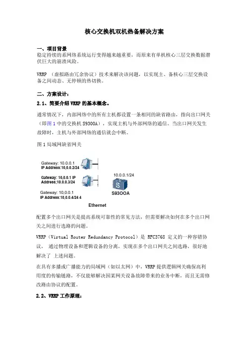
通常情况下,内部网络中的所有主机都设置一条相同的缺省路由,指向出口网关 (即图1中的交换机S9300A ),实现主机与外部网络的通信。
当出口网关发生 故障时,主机与外部网络的通信就会中断。
图1局域网缺省网关Gateway: 10,0.0.1 IP Address:10,0.0.4/24 4Ethernet 配置多个出口网关是提高系统可靠性的常见方法,但需要解决如何在多个出口网 关之间进行选路的问题。
VRRP (Virtual Router Redundancy Protocol )是 RFC3768 定义的一种容错协议, 通过物理设备和逻辑设备的分离,实现在多个出口网关之间选路,很好地解决了 上述问题。
在具有多播或广播能力的局域网(如以太网)中,VRRP 提供逻辑网关确保高利 用度的传输链路,不仅能够解决因某网关设备故障带来的业务中断,而且无需修 改路由协议的配置。
2.2、 V RRP 工作原理:S93OOAGateway: 10.0.0.1IP Address:10,0.0.2/24Gateway: 10,0.0.1 IP Address;10.0.0.3/2410.0.0.1/24vrrp只定义了一种报文—- vrrp报文,这是一种组播报文,由主三层交换机定时发出来通告他的存在。
使用这些报文可以检测虚拟三层交换机各种参数,还可以用于主三层交换机的选举。
VRRP中定义了三种状态模型,初始状态Initialize,活动状态Master 和备份状态Backup,其中只有活动状态的交换机可以为到虚拟IP地址的的转发请求提供服务。
Session Initiation Protocol (SIP):SIP服务器定位本文档状态本文档为Internet 团体定义了一个Internet standards track协议。
并且请求对这个文档进行讨论以便改进。
请参阅当前版本的”InternetOfficalProtocol Stands”(STD1)来确认本文档的标准化状态以及本协议的状态。
对本文档的发布是没有限制的。
版本信息Copyright (C)The Internet Society(2002). All Rights Reserved.概述SIP协议使用了DNS步骤来使得客户端能够把一个标准的SIP格式的资源(SIP URI)解析成为IP地址,端口,以及使用的协议。
同样SIP也支持服务端在客户端的主机失效的情况下使用DNS来向备份的客户端发送应答。
本文档描述了这些DNS的详细过程。
1.介绍SIP(RFC3261)是一个客户端/服务端的协议,它用来创建用户之间的通讯会话和管理用户之间的通讯会话的。
SIP 的终端系统叫做UA(用户代理),中间的结点叫做proxy 服务器。
一个典型的SIP配置,叫做一个SIP”梯形”,就像在图1中表示的一样。
在这个图中,呼叫方在domain A(UA1),希望呼叫在domain B的用户Joe(Joe@b)。
为了完成这个呼叫,他首先和在自己域内部的proxy1(domain A中的proxy 1)。
Proxy1向被叫方域的proxy 服务器(proxy2)转发这个请求。
Proxy2转发这个请求到被叫方,UA2。
作为呼叫流的一部分,proxy1需要确定domain B的SIP服务器。
为了能够确定这个,proxy1 使用DNS的步骤,使用SRV[2]和NAPTR[3]记录来确定这个地址。
本文档描述了SIP使用DNS的相关问题,并且提供了解决方法。
2.DNS需要解决的相关问题为了能够解决上边介绍的一般呼叫流所需要确定的呼叫双方两方面的问题,我们需要使用DNS。
竭诚为您提供优质文档/双击可除http协议数据包格式篇一:数据包格式tcp/ip协议族包括诸如internet协议(ip)、地址解析协议(aRp)、互联网控制信息协议(icmp)、用户数据报协议(udp)、传输控制协议(tcp)、路由信息协议(Rip)、telnet、简单邮件传输协议(smtp)、域名系统(dns)等协议。
tcp/ip 协议的层次结构如图3所示。
图3tcp/ip协议层次结构(1)应用层应用层包含一切与应用相关的功能,相当于osi的上面三层。
我们经常使用的http、Ftp、telnet、smtp 等协议都在这一层实现。
(2)传输层传输层负责提供可靠的传输服务。
该层相当于osi模型中的第4层。
在该层中,典型的协议是tcp(transmissioncontrolprotocol)和udp(userdatagramprotocol)。
其中,tcp提供可靠、有序的,面向连接的通信服务;而udp则提供无连接的、不可靠用户数据报服务。
(3)网际层网际层负责网络间的寻址和数据传输,其功能大致相当于osi模型中的第3层。
在该层中,典型的协议是ip(internetprotocol)。
(4)网络接口层最下面一层是网络接口层,负责数据的实际传输,相当于osi模型中的第1、第2层。
在tcp/ip协议族中,对该层很少具体定义。
大多数情况下,它依赖现有的协议传输数据。
tcp/ip与osi最大的不同在于osi是一个理论上的网络通信模型,而tcp/ip则是实际运行的网络协议。
tcp/ip实际上是由许多协议组成的协议簇。
图4示出tcp/ip的主要协议分类情况。
整个过程:1.dhcp请求ip地址的过程l发现阶段,即dhcp客户端寻找dhcp服务器的阶段。
客户端以广播方式发送dhcpdiscoVeR包,只有dhcp服务器才会响应。
l提供阶段,即dhcp服务器提供ip地址的阶段。
dhcp 服务器接收到客户端的dhcpdiscoVeR报文后,从ip地址池中选择一个尚未分配的ip地址分配给客户端,向该客户端发送包含租借的ip地址和其他配置信息的dhcpoFFeR包。
RFC2326(中文版)-实时流协议(RTSP).txt我的人生有A 面也有B面,你的人生有S面也有B 面。
失败不可怕,关键看是不是成功他妈。
现在的大学生太没素质了!过来拷毛片,居然用剪切!有空学风水去,死后占个好墓也算弥补了生前买不起好房的遗憾。
实时流协议(RTSP) ( Real Time Streaming Protocol (RTSP) )备忘录的状态:本文档讲述了一种Internet社区的Internet标准跟踪协议,它需要进一步进行讨论和建议以得到改进。
请参考最新版的“Internet正式协议标准”(STD1)来获得本协议的标准化程度和状态。
本备忘录的发布不受任何限制。
版权声明:版权为The Internet Society 所有。
所有权利保留。
摘要:实时流协议(RTSP)是应用层协议,控制实时数据的传送。
RTSP提供了一个可扩展框架,使实时数据,如音频与视频的受控、点播成为可能。
数据源包括现场数据与存储在剪辑中数据。
该协议目的在于控制多个数据发送连接,为选择发送通道,如UDP、组播UDP与TCP,提供途径,并为选择基于RTP(RFC1889)上传送机制提供方法。
目录:1 绪论 51.1 目的 51.2 要求 61.3 术语 61.4 协议特点 71.5 RTSP扩展 81.6 操作模式 91.7 RTSP状态 91.8 与其他协议关系 102 符号协定 103 协议参数 103.1 RTSP版本 103.2 RTSP URL 113.3 会议标识 133.4 会话标识 133.5 SMPTE 相对时间戳 133.6正常播放时间 143.7 绝对时间 153.8 选择标签 153.8.1 用IANA注册新的选择标签 154 RTSP消息 154.1 消息类型 164.2 消息标题 174.3 消息主体 174.4 消息长度 185 普通标题域 186 请求 196.1 请求队列 196.2 请求标题域 197 回应 207.1 状态行 207.1.1 状态代码和原因分析 207.1.2 回应标题域 238 实体 238.1 实体标题域 248.2 实体主体 249 连接 259.1 流水线操作 259.2 可靠性及确认 2510 方法定义 2510.1 选择 2610.2 描述 2610.3 通告 2610.4 建立 2610.5 播放 2710.6 暂停 2710.7 断开 2710.8 获取参数 2810.9 设置参数 2810.10 重定向 2810.11 录制 2910.12 嵌入二进制数据 2911状态代码定义(Status Code Definitions) 29 11.1成功2xx(Success 2xx) 3011.1.1 存储空间低 250 3011.2 重定向(Redirection 3xx) 3111.3 客户端错误(Client Error )4xx 3111.3.1方法不允许 3211.3.2参数不能理解 3211.3.3会议未找到 3311.3.4 带宽不足 3311.3.5 会话未找到 3411.3.6 本状态下该方法无效 3411.3.7 标题域对资源无效 3411.3.8 无效范围 3511.3.9 参数只读 3511.3.10 不允许合操作 3611.3.11 只允许合操作 3611.3.12 不支持的传输 3611.3.13 目标不可达 3711.3.14 选择不支持 3712 标题域定义(Header Field Definitions) 38 12.1 接受 3812.2 接受编码 3812.3 接受语言 3912.4 允许(Allow) 3912.5 授权(Authorization) 4012.6 带宽 4012.7 块大小 4012.8 缓存控制 4112.9 会议 4112.10 连接 4112.11 基本内容 4212.12 内容编码(Content-Encoding) 4212.13 内容语言 4312.14 内容长度(Content-Length) 4312.15 内容位置 4312.16 内容类型(Content-Type) 4412.17 序列号 4412.18 日期(Date) 4412.19 过期(Expires) 4512.20 来自(From) 4512.21 主机 4512.22 如果匹配 4512.23 从何时更改(If-Modified-Since) 46 12.24 最近更改(Last-Modified) 4612.25 位置(Location) 4612.26 代理授权 4712.27 代理要求 4712.28 公用性 4712.29 范围 4912.30 提交方(Referer) 4912.31 稍后再试 4912.32 要求 4912.33 RTP信息 4912.34 比例 4912.35 速度 4912.36 服务器(Server) 4912.37 会话 4912.38 时间戳 4912.39 传输 4912.40 不支持 4912.41 用户代理(User-Agent) 4912.42 变化 4912.43 通过 4912.44 WWW-授权(WWW-Authenticate) 5013 缓存 5014 实例 5014.1 要求媒体(单播) 5014.2 容器文件的流 5114.3 单个流容器文件 5114.4 组播现场媒体表示 5114.5 在存在的会话中播放媒体 5114.6 录制 5215 语法 5215.1 基本语法 5216 安全考虑(Security Considerations) 52 附录A RTSP协议状态机 53A.1 客户端状态机 53A.2 服务器端状态机 53附录B 同RTP协议的交互 53附录C 使用SDP进行RTSP会话描述 54C.1 定义 54C.1.1 控制URL 55C.1.2 媒体流 55C.1.3 有效载荷类型 55C.1.4 详细格式参数 55C.1.5 表示的范围 56C.1.6 有效时间 56C.1.7 连接信息 56C.1.8 实体标签 57C.2 合控制不可用 57C.3 合控制可用 57附录D 最简单的RTSP实现 58D.1 客户端 58D.1.1回放 58D.1.2 授权 58D.2 服务器 59D.2.1回放 59D.2.2授权 59附录E 作者地址 60附录F 致谢 60参考书目 60版权申明 611 绪论1.1 目的实时流协议(RTSP)建立并控制一个或几个时间同步的连续流媒体。
August 2017Current HP Download Manager===========================A.04.30 (RECOMMENDED UPGRADE)Supports IPv6 on Microsoft Vista/Windows 7.Supports SNMPv1/v2c over IPv4 and IPv6.Supports SNMPv3 over IPv4 and IPv6Supports TCP upgrades with HP Jetdirect firmware V.36.11 and later Supports TFTP/UDP upgrades will all HP Jetdirect firmware versions. Current HP Jetdirect Firmware List for Upgradeable Products=========================================================== Embedded--------J7949E V.33.21EIO---600nJ3110A G.08.49J3111A G.08.49J3112A G.08.49J3113A G.08.49610nJ4167A L.25.47J4169A L.25.57615nJ6057A R.25.57620nJ7934A V.29.26J7934G V.29.26625nJ7960A V.29.20J7960G V.29.20630nJ7997G V.38.05635nJ7961A V.41.16J7961G V.41.16640nJ8025A V.45.39680nJ6058A U.25.39690nJ8007G V.41.16695nJ8024A V.45.39LIO---250mJ6042B N.25.47280mJ6044A T.25.39MIO---400nJ4100A K.08.49 J4105A K.08.49 J4106A K.08.49 LegacyJ2550B A.08.49 J2552B A.08.49 J2555B A.08.49 J2550A A.05.05 J2552A A.05.05J2555A A.05.06J2556B A.05.35J2371A C.03.19J2372A C.03.19J2373A C.03.19External - USB--------------310xJ6038A Q.25.49380xJ6061A S.25.39ew2400J7951A V.28.87J7951G V.28.87ew2500J8021A V.41.19en3700J7942A V.28.22J7942G V.28.22en1700J7988G V.36.12External - Parallel-------------------300xJ3263A H.08.67J3263G H.08.67500xJ3264A J.08.49J3265A J.08.67510xJ7983G J.08.67Legacy External - Parallel --------------------------J2591A E.08.49J2593A D.08.49J2594A D.08.49J2382A B.03.19J2382B B.03.19J2383B B.03.19HP Download Manager Readme==========================A.04.30 (RECOMMENDED UPGRADE)1. Improved Discovery.2. Improved downloading of IR's.A.04.201. Improved Download Performance – TCP download support instead of TFTP.2. SNMPv3 support.3. IPV6 support.A.03.12A.03.11 would sometimes show that was unavailable using Internet Mode. A.03.12improves that process.A.03.11 includes an enhancement that allows for the latest firmware catalog to be downloaded from rather than using a potentially cached copy.Current Jetdirect Firmware Readme for Upgradeable Products==========================================================V.45.39 Firmware - 640n/695n----------------------------* replace self-signed MD5 certificate with new SHA 256 self-signed certificate.* CVE-2016-2183 -- Sweet32 vulnerability.3DES deprecation to MEDIUM.* RC4 deprication to LOW.* CVE-2017-9765 -- Integer overflow in SOAP (Simple Object Access Protocol) function allows execution of arbitrary code or Denial of Service, aka Devil's Ivy attack* Fix for Clickjacking attack vulnerabilityV.41.19 Firmware - ew2500-------------------------* CVE-2016-2183 -- Sweet32 vulnerability.3DES deprecation to MEDIUM.* RC4 deprication to LOW.* Organization name change in selfsigned certificate from "Hewlett-Packard" to HP Inc."V.45.36 Firmware - 640n/695n----------------------------* addresses the following security issues:OpenSSL vulnerability CVE-2014-0224 (“CCS Injection”) was fixedSSL protocol versions 3.0 and 2.0 were removedCompliant with new European ETSI EN 300 328 v1.8.1 regulationsV.45.35 Firmware - 640n/695n----------------------------* addresses the following security issues:CVE-2014-0224 - SSL/TLS MITM vulnerabilityCVE-2014-3566 – SSLv3 POODLE (Padding Oracle on Downgraded Legacy Encryption) VulnerabilityV.41.16 Firmware - ew2500/635n/690n-----------------------------------* addresses the following security issues:CVE-2014-0224 - SSL/TLS MITM vulnerabilityCVE-2014-3566 – SSLv3 POODLE (Padding Oracle on Downgraded Legacy Encryption) VulnerabilityV.29.26 Firmware - 620n-----------------------* addresses the following security issues:CVE-2014-0224 - SSL/TLS MITM vulnerabilityCVE-2014-3566 – SSLv3 POODLE (Padding Oracle on Downgraded Legacy Encryption) VulnerabilityV.45.18 Firmware - 640n/695n----------------------------* Security Minimum Compliance changes, OpenSSL, IPSEC, SNMPv3 Upgrade* Increase number of IKE connection to 60* Added-micron-spi-flash-support* Automatic location of Printer through UPD improvementsV.41.14 Firmware - ew2500-------------------------* IPSec enhancements* 802.1x improvements* WS discovery improvementsV.41.12 Firmware - 635n/690n----------------------------* TLS/SSL RFC5746 support for TLS Re-Negotiation* 2048 bit SSL encryption* Reflected XSS vulnerability in which the EWS "reflects" a URL to the browser without screening the URL for potentially malicious HTML.* OpenSSL 0.9.8 vulnerable to Ciphersuite downgrade attack* Certificate Signing Request page now defaults to 2048 bits rather than 1024* EWS Logout/Sign In improvments for IE9* Nmap Matrix for Scanjet cprinterXXError message.* 690N wireless robustness improvementsV.41.12 Firmware - ew2500-------------------------* TLS/SSL RFC5746 support for TLS Re-Negotiation* ew2500 wireless robustness improvementsV.41.08 Firmware - 635n----------------------------* LDAP over SSL enhancements* 802.1x PEAP compatible with FreeRadiusV.41.05 Firmware - 690n----------------------------* Certification to be fully compliant with USGv6 standard recommended by NIST(The National Institute for Standards and Technology-USGovernment)for any procurement in US Government agencies.* USGv6 mandated security RFCs and IPsec-IKEv2 support.* IPv6 RFC support for RFCs3484, 3306, 3307, 3879 & 2526* IPv6 RFC support for MLDv2* Certified as a “Simple Host” supporting IPv6 Host, IPsec, IKEv2 requirements of USGv6 specification by accredited lab.* Added support for configuring SSID on printer control panelV.38.05 Firmware - 630n/635n----------------------------* Added 802.1x disable on control panel* Improved security pages* Added DHCP FQDN for IPv6* Simplified fleet management of SecurityV.36.12 Firmware (en1700)-----------------------------------------------------* Added Push Button EFIGS config pages* Improved SNMP response times with LJP2055* Improved Toolbox experience with CLJ CP2025V.33.21 Firmware - Embedded Jetdirect Products----------------------------------------------* Open SSL memory improvements* PEAP Crypto Binding for Win Server 2008* RST and ACKs between HP-UX and HP Printer in LPD printing improved* Successful installation of Identity certificate in the place of CA certificateV.33.19 Firmware - Embedded Jetdirect Products----------------------------------------------* EWS memory improvements* Performance improvements during high loads in large networks* Printer status indications were improved for IPP* Printer prefix/suffix strings longer than 32 characters in LPD improved * DNS update protocol was strengthenedV.33.14 Firmware - Embedded Jetdirect Products----------------------------------------------* More Improved handling of 8X Service Error 1BAE conditions* Improved handling of Windows X509v3 Certificates for SSLapplications residing on the printer/MFP.V.33.12 Firmware - Embedded Jetdirect Products----------------------------------------------* Improved the handling of long SNMP community names* 802.1X supportV.29.20 Firmware - 620n/625n----------------------------* More Improved handling of 8X Service Error 1BAE conditionsV.29.19 Firmware - 620n/625n----------------------------* Improved the handling of long SNMP community names* Improved handling of IP addresses that have a zero octetembedded in the address.* Improved DHCP handling with short lease times* Improved handling of IP packets with non-zero TOS field* Improved EIO Jetdirect handling of 8X SE 1BAE ConditionV.28.22 Firmware (en3700) / V.28.87 Firmware (ew2400)-----------------------------------------------------* Better USB printer compatibility and web scan support* Improved the handling of long SNMP community names* Improved handling of IP addresses that have a zero octetembedded in the address.* Improved DHCP handling with short lease times* Improved handling of IP packets with non-zero TOS fieldX.25.47/49/57 Firmware----------------* Improved the handling of long SNMP community names* Improved handling of IP addresses that have a zero octetembedded in the address.* Improved DHCP handling with short lease times* Improved handling of IP packets with non-zero TOS field* Improved EIO Jetdirect handling of 8X SE 1BAE Condition* Better USB printer compatibility and web scan support* Now responding to ICMP Echo Requests when the IP Header TOS bits areset* Added the ability to configure via telnet a keep alive packet forcertainswitch environments. Default is disabled (0). If a non-zero value is entered,Jetdirect will send a simple multicast SLP announcement each intervalue specified. The interval is in minutes.slp-keep-alive: (0 to disable, 1..1440 to enable)* Applied OpenSSL security patches* Improved DHCP packet processing* Improved resistance to FTP Denial of Service attacks* Added telnet command to disable participation in sharing of customer information withoutlogging a refusal to HP. When the "Networking" tab of the Embedded Web Server is accessedthe adminstrator is asked whether they would like to send HPinformation to help HPunderstand how HP's products are used. If the administrator indicates "No", this refusalis logged to HP. Some customers do not want this refusal to berecorded to HP. As aresult, the customer can telnet into the Jetdirect device and initiate the followingcommand:phone-home-config: (0 to disable, 1 to enable)The result is that the answer to the question is assumed to be "No" and the refusal isnot sent to HP.X.25.39 Wireless Firmware-------------------------The following improvements were added to existing functionality* S.25.39, T.25.39, U.25.39 Wireless Firmware Update- DHCP Improvements- Improved interoperability with AP420, AP1200- Improved authentication algorithms- Allowing for larger certificates to be loaded- Improved reconfiguration message handlingX.08.67-------* Improved PML trap behavior on a power cycle* Added releasing a trap for RGP user reporter for WebJet 8.0 when a job printsX.08.60-------* Improved DHCP Lease time handling* Misc. improvementsX.08.49-------* Corrected IPX download problem on X.08.46/X.08.47* Improved DHCP Offer handling* Improved the network upgrade process for the J2550B, J2552B, andJ2555B MIO products* Retained the SNMP Set Community Name across a download* Improved TFTP configuration file parsing and added support forspecifying the password* Improved WINS Algorithm. HP Jetdirect will no longer reconfigure the hostname when a WINS Name clash is detect. Instead, it will simplypost a message to the configuration page* Added telnet/tftp ability to disable the default get community names. formatdefault-get-cmnty: 0 to disable, 1 to enableNOTE: If a get community name is not specified and the default getcommunity names have been disabled, then SNMP read access iseffectivelydisabled.* Improved LPD processing when connected to slow printers on externalprint servers.* Allowed the hostname to be retained when switching from a manualconfiguration to a dynamic configuration.* Implemented functionality to allow Jetdirect cards to respond toWINS node status requests.* Invalid SNMP traps could be set in the Trap Destination Table. Animprovement was made to detect and reject this configuration.* Prevented configuration loss when downloading via Web Jetadmin* Corrected web page pointed to by the support tab in the Embedded Web Server* Allowed Office-Jet D series printers to support web scan.* CERT Vulnerability Note VU#412115 has been fixed.* External products could only negotiate Bidirectional with HP LaserJet4200 and 4300 series products. Improved functionality to allow forECP2/MLC connectivity via the parallel port.* Implemented password synchronization between management applications. Now, WJA, Telnet, and the Embedded Web Server can all share thesame password.Also, refer to HP's Secure Printing website:/go/secureprintingThank you for your continued support of HP Jetdirect products.。
rfc中常用的测试协议摘要:1.RFC 简介2.RFC 中常用的测试协议a.网络协议测试1.网络数据包抓取和分析2.网络仿真和测试工具b.应用层协议测试1.HTTP 和HTTPS 测试2.FTP 和FTPS 测试3.SMTP 和SMTPS 测试c.安全协议测试1.TLS 和SSL 测试2.IPsec 测试d.传输协议测试1.TCP 和UDP 测试e.无线网络协议测试1.802.11 无线网络测试正文:RFC(Request for Comments)是一个用于讨论和记录互联网协议的标准文档系列。
在RFC 中,有许多常用的测试协议,这些协议用于确保互联网协议在实际应用中能够正常工作。
本文将详细介绍这些测试协议。
首先,RFC 中包含了大量的网络协议测试。
网络数据包抓取和分析是网络协议测试的基础,这对于诊断网络问题和优化网络性能至关重要。
此外,网络仿真和测试工具也是必不可少的,例如,网络模拟器(如NS-3)和测试平台(如Ixia)可以帮助工程师在实验室环境中模拟实际网络状况,从而对协议进行更严格的测试。
其次,应用层协议测试在RFC 中也占据重要地位。
HTTP 和HTTPS 是Web 应用中最常用的协议,有许多测试工具可以对它们的性能和安全性进行测试,例如,JMeter 和Locust 等负载测试工具。
此外,FTP 和FTPS、SMTP 和SMTPS 等传输协议也是常用的测试对象。
在安全协议方面,RFC 中包含了TLS 和SSL、IPsec 等协议的测试方法。
这些协议对于保护互联网数据传输的安全至关重要,因此需要进行严格的测试以确保其性能和安全性。
传输协议方面,TCP 和UDP 是互联网中最常用的传输协议,它们的测试方法也是RFC 中的重要内容。
TCP 测试关注可靠性和流量控制等方面,而UDP 测试则更注重数据传输速率和丢包率等指标。
最后,无线网络协议测试在RFC 中也有一定的比重。
例如,802.11 无线网络测试是评估无线局域网性能的关键。
附件4:企业秘密中国电信IP城域网设备测试规范(汇聚交换机)(V2.0)中国电信集团公司二零零六年一月目录1. 概述 (1)1.1范围 (1)1.2引用标准 (1)1.3缩略语 (2)2. 测试环境和仪表 (3)2.1测试环境 (3)2.2测试仪表 (3)3. 测试内容 (4)4. 二层交换功能测试 (4)4.1基本功能测试 (4)4.1.1 超长帧转发能力 (4)4.1.2 异常帧检测功能测试 (5)4.1.3 广播抑制功能测试 (6)4.2镜像功能 (6)4.2.1 端口镜像功能测试 (6)4.2.2 流镜像功能测试 (7)4.3生成树协议测试 (8)4.3.1 标准生成树测试 (8)4.3.2 快速生成树测试 (9)4.3.3 多生成树测试 (10)4.4VLAN堆叠功能测试 (11)4.4.1 基本功能 (11)4.4.2 扩展功能 (12)4.5端口聚合 (14)4.5.1 聚合链路数量测试 (14)4.5.2 聚合效率测试 (15)4.5.3 聚合链路收敛时间测试 (16)4.6二层组播功能测试 (17)4.6.1 UNTAGGED端口IGMP SNOOPING功能测试 (17)4.6.2 TAGGED端口IGMP SNOOPING功能测试 (18)4.6.3 组播组加入/离开时间测试 (19)4.7P RIV ATE V LAN功能测试 (20)4.8V LAN交换功能测试 (21)5. 访问控制和QOS功能 (22)5.1访问控制表方向性测试 (22)5.2二层访问控制表测试 (23)5.2.1 MAC地址访问控制表测试 (23)5.2.2 VLAN访问控制表测试 (23)5.2.4 SVLAN访问控制表测试 (25)5.3三层访问控制表功能测试 (26)5.3.1 IP地址访问控制表功能测试 (26)5.3.2 四层端口访问控制表功能测试 (26)5.4访问控制表数量及性能测试 (27)5.5业务分级 (28)5.5.1 基于VLAN ID的业务分级 (28)5.5.2 基于四层端口的业务分级 (29)5.5.3 SVLAN内外层标签802.1P优先级映射 (30)5.6优先级队列 (31)5.6.1 严格优先级队列 (31)5.6.2 轮询队列 (31)5.7速率限制 (32)5.7.1 入方向速率限制功能测试 (32)5.7.2 出方向速率限制功能测试 (33)5.7.3 速率限制颗粒度及精确性测试 (34)6. 转发性能测试 (35)6.1MAC地址学习速度 (35)6.2MAC地址表容量 (35)6.3最大VLAN数量测试 (36)6.4单端口吞吐量和时延测试 (37)6.5板内交换性能测试 (38)6.6板间交换性能测试 (39)6.7综合转发性能测试 (40)7. 可靠性和安全性 (41)7.1设备可靠性 (41)7.1.1 主控板和交换矩阵冗余 (41)7.1.2 电源冗余 (42)7.1.3 业务卡热插拔 (42)7.1.4 设备重启动时间 (43)7.2网络安全 (44)7.2.1 端口地址数量限制 (44)7.2.2 设备防ARP攻击测试 (45)7.2.3 设备防ICMP攻击测试 (45)7.2.4 设备防BPDU攻击测试 (46)8. 运行维护和网络管理 (47)8.1运行维护功能测试 (47)8.1.1 远程认证管理 (47)8.1.2 SSH登录测试 (48)8.1.3 日志记录 (48)8.1.4 DHCP Option82功能测试 (49)8.2.1 SNMPv1、SNMPv2支持测试 (50)8.2.2 SNMPv3支持测试 (50)8.2.3 SNMP访问地址限制 (51)8.2.4 MIB View安全访问控制功能测试 (52)8.2.5 SNMP Trap功能测试 (52)8.3管理信息库 (53)8.3.1 端口MIB的功能测试 (53)8.3.2 VLAN MIB的功能测试 (53)8.3.3 CPU利用率、内存占用率的功能测试 (54)8.3.4 资源管理信息功能测试 (54)8.3.5 ACL管理信息功能测试 (55)8.3.6 QOS的管理功能测试 (55)8.3.7 二层组播MIB (56)8.3.8 SVLAN MIB (56)中国电信IP城域网设备测试规范-汇聚交换机1. 概述1.1 范围本规范主要参考我国相关标准、RFC标准、国际电信联盟ITU-T相关建议以及《中国电信城域网优化改造指导意见》、《中国电信城域网设备技术规范》编制。
中国电信cdma2000核心网络设备技术要求—AN-AAA(初稿V1.0)中国电信股份有限公司广东研究院二零零八年三月内部修改记录目录1范围 (1)2引用标准 (1)3缩略语 (1)4概述 (2)5协议要求 (3)6AN-AAA设备功能要求 (4)6.1UIM卡的区分功能 (4)6.2对使用新卡终端的鉴权功能 (5)6.3对使用旧卡终端的鉴权功能 (5)6.3.1CAVE算法的支持 (5)6.3.2鉴权失败计数器和门限值 (6)6.3.3SSD同步计数器和门限值 (7)6.4接口功能 (8)6.4.1AN-AAA与AN之间的接口 (8)6.4.2AN-AAA与HLR/AC之间的接口 (8)6.4.3AN-AAA与iSPP的接口 (8)6.4.4网管接口 (8)6.4.5NAI格式 (9)6.5漫游功能 (9)6.6用户免除鉴权功能 (9)7性能要求 (10)7.1AN-AAA服务器支持的用户数目 (10)7.2AN-AAA服务器同时处理的认证数目 (10)7.3AN-AAA服务器处理认证的时间 (10)7.4AN-AAA可靠性要求 (11)8接口要求 (11)8.1AN-AAA与AN之间的接口 (11)8.1.1接口描述 (11)8.1.2消息格式 (12)8.2AN-AAA与HLR/AC之间的接口 (14)8.2.1接口描述 (14)8.2.2消息格式 (15)8.3AN-AAA与I SPP的接口 (17)8.4网管接口 (17)9环境要求 (18)9.1正常工作的温度、湿度条件 (18)9.2防尘要求 (18)9.3防电磁干扰要求 (18)9.4抗电磁干扰的能力 (19)9.5防雷击能力 (19)10电源与接地 (20)10.1电源 (20)10.2接地要求 (20)附录 A 基于CA VE算法的鉴权信令流程 (21)A.1新用户鉴权成功 (21)A.2SSD共享情况下鉴权成功 (22)A.3AN-AAA定期同步SSD成功 (23)A.4AN-AAA鉴权失败,HLR/AC鉴权成功 (23)A.5HLR/AC鉴权失败,返回D ENY A CCESS (23)A.6HLR/AC鉴权失败,返回RANDSSD (24)A.7永久拒绝用户接入 (25)前言《中国电信cdma2000核心网络设备技术要求》是在参考3GPP2等国际标准化组织和CCSA颁布的相关技术标准的基础上,结合第三代移动通信的技术发展、中国电信承接cdma2000网络以及现有网络的实际情况制定,设备对象是LMSD电路域和EVDO Rev.A分组域设备。
Network Working Group C. Kaufman, Ed. Request for Comments: 4306 Microsoft Obsoletes: 2407, 2408, 2409 December 2005 Category: Standards TrackInternet Key Exchange (IKEv2) ProtocolStatus of This MemoThis document specifies an Internet standards track protocol for the Internet community, and requests discussion and suggestions forimprovements. Please refer to the current edition of the "InternetOfficial Protocol Standards" (STD 1) for the standardization stateand status of this protocol. Distribution of this memo is unlimited. Copyright NoticeCopyright (C) The Internet Society (2005).AbstractThis document describes version 2 of the Internet Key Exchange (IKE) protocol. IKE is a component of IPsec used for performing mutualauthentication and establishing and maintaining security associations (SAs).This version of the IKE specification combines the contents of whatwere previously separate documents, including Internet SecurityAssociation and Key Management Protocol (ISAKMP, RFC 2408), IKE (RFC 2409), the Internet Domain of Interpretation (DOI, RFC 2407), Network Address Translation (NAT) Traversal, Legacy authentication, andremote address acquisition.Version 2 of IKE does not interoperate with version 1, but it hasenough of the header format in common that both versions canunambiguously run over the same UDP port.Kaufman Standards Track [Page 1]Table of Contents1. Introduction (3)1.1. Usage Scenarios (5)1.2. The Initial Exchanges (7)1.3. The CREATE_CHILD_SA Exchange (9)1.4. The INFORMATIONAL Exchange (11)1.5. Informational Messages outside of an IKE_SA (12)2. IKE Protocol Details and Variations (12)2.1. Use of Retransmission Timers (13)2.2. Use of Sequence Numbers for Message ID (14)2.3. Window Size for Overlapping Requests (14)2.4. State Synchronization and Connection Timeouts (15)2.5. Version Numbers and Forward Compatibility (17)2.6. Cookies (18)2.7. Cryptographic Algorithm Negotiation (21)2.8. Rekeying (22)2.9. Traffic Selector Negotiation (24)2.10. Nonces (26)2.11. Address and Port Agility (26)2.12. Reuse of Diffie-Hellman Exponentials (27)2.13. Generating Keying Material (27)2.14. Generating Keying Material for the IKE_SA (28)2.15. Authentication of the IKE_SA (29)2.16. Extensible Authentication Protocol Methods (31)2.17. Generating Keying Material for CHILD_SAs (33)2.18. Rekeying IKE_SAs Using a CREATE_CHILD_SA exchange (34)2.19. Requesting an Internal Address on a Remote Network (34)2.20. Requesting the Peer’s Version (35)2.21. Error Handling (36)2.22. IPComp (37)2.23. NAT Traversal (38)2.24. Explicit Congestion Notification (ECN) (40)3. Header and Payload Formats (41)3.1. The IKE Header (41)3.2. Generic Payload Header (44)3.3. Security Association Payload (46)3.4. Key Exchange Payload (56)3.5. Identification Payloads (56)3.6. Certificate Payload (59)3.7. Certificate Request Payload (61)3.8. Authentication Payload (63)3.9. Nonce Payload (64)3.10. Notify Payload (64)3.11. Delete Payload (72)3.12. Vendor ID Payload (73)3.13. Traffic Selector Payload (74)3.14. Encrypted Payload (77)Kaufman Standards Track [Page 2]3.15. Configuration Payload (79)3.16. Extensible Authentication Protocol (EAP) Payload (84)4. Conformance Requirements (85)5. Security Considerations (88)6. IANA Considerations (90)7. Acknowledgements (91)8. References (91)8.1. Normative References (91)8.2. Informative References (92)Appendix A: Summary of Changes from IKEv1 (96)Appendix B: Diffie-Hellman Groups (97)B.1. Group 1 - 768 Bit MODP (97)B.2. Group 2 - 1024 Bit MODP (97)1. IntroductionIP Security (IPsec) provides confidentiality, data integrity, access control, and data source authentication to IP datagrams. Theseservices are provided by maintaining shared state between the source and the sink of an IP datagram. This state defines, among otherthings, the specific services provided to the datagram, whichcryptographic algorithms will be used to provide the services, andthe keys used as input to the cryptographic algorithms.Establishing this shared state in a manual fashion does not scalewell. Therefore, a protocol to establish this state dynamically isneeded. This memo describes such a protocol -- the Internet KeyExchange (IKE). This is version 2 of IKE. Version 1 of IKE wasdefined in RFCs 2407, 2408, and 2409 [Pip98, MSST98, HC98]. Thissingle document is intended to replace all three of those RFCs.Definitions of the primitive terms in this document (such as Security Association or SA) can be found in [RFC4301].Keywords "MUST", "MUST NOT", "REQUIRED", "SHOULD", "SHOULD NOT" and"MAY" that appear in this document are to be interpreted as described in [Bra97].The term "Expert Review" is to be interpreted as defined in[RFC2434].IKE performs mutual authentication between two parties andestablishes an IKE security association (SA) that includes sharedsecret information that can be used to efficiently establish SAs for Encapsulating Security Payload (ESP) [RFC4303] and/or Authentication Header (AH) [RFC4302] and a set of cryptographic algorithms to beused by the SAs to protect the traffic that they carry. In thisdocument, the term "suite" or "cryptographic suite" refers to a Kaufman Standards Track [Page 3]complete set of algorithms used to protect an SA. An initiatorproposes one or more suites by listing supported algorithms that can be combined into suites in a mix-and-match fashion. IKE can alsonegotiate use of IP Compression (IPComp) [IPCOMP] in connection with an ESP and/or AH SA. We call the IKE SA an "IKE_SA". The SAs forESP and/or AH that get set up through that IKE_SA we call"CHILD_SAs".All IKE communications consist of pairs of messages: a request and a response. The pair is called an "exchange". We call the firstmessages establishing an IKE_SA IKE_SA_INIT and IKE_AUTH exchangesand subsequent IKE exchanges CREATE_CHILD_SA or INFORMATIONALexchanges. In the common case, there is a single IKE_SA_INITexchange and a single IKE_AUTH exchange (a total of four messages) to establish the IKE_SA and the first CHILD_SA. In exceptional cases,there may be more than one of each of these exchanges. In all cases, all IKE_SA_INIT exchanges MUST complete before any other exchangetype, then all IKE_AUTH exchanges MUST complete, and following thatany number of CREATE_CHILD_SA and INFORMATIONAL exchanges may occurin any order. In some scenarios, only a single CHILD_SA is neededbetween the IPsec endpoints, and therefore there would be noadditional exchanges. Subsequent exchanges MAY be used to establish additional CHILD_SAs between the same authenticated pair of endpoints and to perform housekeeping functions.IKE message flow always consists of a request followed by a response. It is the responsibility of the requester to ensure reliability. If the response is not received within a timeout interval, the requester needs to retransmit the request (or abandon the connection).The first request/response of an IKE session (IKE_SA_INIT) negotiates security parameters for the IKE_SA, sends nonces, and sends Diffie-Hellman values.The second request/response (IKE_AUTH) transmits identities, provesknowledge of the secrets corresponding to the two identities, andsets up an SA for the first (and often only) AH and/or ESP CHILD_SA. The types of subsequent exchanges are CREATE_CHILD_SA (which creates a CHILD_SA) and INFORMATIONAL (which deletes an SA, reports errorconditions, or does other housekeeping). Every request requires aresponse. An INFORMATIONAL request with no payloads (other than the empty Encrypted payload required by the syntax) is commonly used as a check for liveness. These subsequent exchanges cannot be used until the initial exchanges have completed.Kaufman Standards Track [Page 4]In the description that follows, we assume that no errors occur.Modifications to the flow should errors occur are described insection 2.21.1.1. Usage ScenariosIKE is expected to be used to negotiate ESP and/or AH SAs in a number of different scenarios, each with its own special requirements.1.1.1. Security Gateway to Security Gateway Tunnel+-+-+-+-+-+ +-+-+-+-+-+! ! IPsec ! !Protected !Tunnel ! tunnel !Tunnel ! ProtectedSubnet <-->!Endpoint !<---------->!Endpoint !<--> Subnet! ! ! !+-+-+-+-+-+ +-+-+-+-+-+Figure 1: Security Gateway to Security Gateway TunnelIn this scenario, neither endpoint of the IP connection implementsIPsec, but network nodes between them protect traffic for part of the way. Protection is transparent to the endpoints, and depends onordinary routing to send packets through the tunnel endpoints forprocessing. Each endpoint would announce the set of addresses"behind" it, and packets would be sent in tunnel mode where the inner IP header would contain the IP addresses of the actual endpoints.1.1.2. Endpoint-to-Endpoint Transport+-+-+-+-+-+ +-+-+-+-+-+ ! ! IPsec transport ! ! !Protected! or tunnel mode SA !Protected! !Endpoint !<---------------------------------------->!Endpoint ! ! ! ! ! +-+-+-+-+-+ +-+-+-+-+-+Figure 2: Endpoint to EndpointIn this scenario, both endpoints of the IP connection implementIPsec, as required of hosts in [RFC4301]. Transport mode willcommonly be used with no inner IP header. If there is an inner IPheader, the inner addresses will be the same as the outer addresses.A single pair of addresses will be negotiated for packets to beprotected by this SA. These endpoints MAY implement applicationlayer access controls based on the IPsec authenticated identities of the participants. This scenario enables the end-to-end security that has been a guiding principle for the Internet since [RFC1958], Kaufman Standards Track [Page 5][RFC2775], and a method of limiting the inherent problems withcomplexity in networks noted by [RFC3439]. Although this scenariomay not be fully applicable to the IPv4 Internet, it has beendeployed successfully in specific scenarios within intranets usingIKEv1. It should be more broadly enabled during the transition toIPv6 and with the adoption of IKEv2.It is possible in this scenario that one or both of the protectedendpoints will be behind a network address translation (NAT) node, in which case the tunneled packets will have to be UDP encapsulated sothat port numbers in the UDP headers can be used to identifyindividual endpoints "behind" the NAT (see section 2.23).1.1.3. Endpoint to Security Gateway Tunnel+-+-+-+-+-+ +-+-+-+-+-+! ! IPsec ! ! Protected!Protected! tunnel !Tunnel ! Subnet!Endpoint !<------------------------>!Endpoint !<--- and/or! ! ! ! Internet+-+-+-+-+-+ +-+-+-+-+-+Figure 3: Endpoint to Security Gateway TunnelIn this scenario, a protected endpoint (typically a portable roaming computer) connects back to its corporate network through an IPsec-protected tunnel. It might use this tunnel only to accessinformation on the corporate network, or it might tunnel all of itstraffic back through the corporate network in order to take advantage of protection provided by a corporate firewall against Internet-based attacks. In either case, the protected endpoint will want an IPaddress associated with the security gateway so that packets returned to it will go to the security gateway and be tunneled back. This IP address may be static or may be dynamically allocated by the security gateway. In support of the latter case, IKEv2 includes a mechanismfor the initiator to request an IP address owned by the securitygateway for use for the duration of its SA.In this scenario, packets will use tunnel mode. On each packet from the protected endpoint, the outer IP header will contain the sourceIP address associated with its current location (i.e., the addressthat will get traffic routed to the endpoint directly), while theinner IP header will contain the source IP address assigned by thesecurity gateway (i.e., the address that will get traffic routed tothe security gateway for forwarding to the endpoint). The outerdestination address will always be that of the security gateway,while the inner destination address will be the ultimate destination for the packet.Kaufman Standards Track [Page 6]In this scenario, it is possible that the protected endpoint will be behind a NAT. In that case, the IP address as seen by the securitygateway will not be the same as the IP address sent by the protected endpoint, and packets will have to be UDP encapsulated in order to be routed properly.1.1.4. Other ScenariosOther scenarios are possible, as are nested combinations of theabove. One notable example combines aspects of 1.1.1 and 1.1.3. Asubnet may make all external accesses through a remote securitygateway using an IPsec tunnel, where the addresses on the subnet are routed to the security gateway by the rest of the Internet. Anexample would be someone’s home network being virtually on theInternet with static IP addresses even though connectivity isprovided by an ISP that assigns a single dynamically assigned IPaddress to the user’s security gateway (where the static IP addresses and an IPsec relay are provided by a third party located elsewhere).1.2. The Initial ExchangesCommunication using IKE always begins with IKE_SA_INIT and IKE_AUTHexchanges (known in IKEv1 as Phase 1). These initial exchangesnormally consist of four messages, though in some scenarios thatnumber can grow. All communications using IKE consist ofrequest/response pairs. We’ll describe the base exchange first,followed by variations. The first pair of messages (IKE_SA_INIT)negotiate cryptographic algorithms, exchange nonces, and do aDiffie-Hellman exchange [DH].The second pair of messages (IKE_AUTH) authenticate the previousmessages, exchange identities and certificates, and establish thefirst CHILD_SA. Parts of these messages are encrypted and integrity protected with keys established through the IKE_SA_INIT exchange, so the identities are hidden from eavesdroppers and all fields in allthe messages are authenticated.In the following descriptions, the payloads contained in the message are indicated by names as listed below.Notation PayloadAUTH AuthenticationCERT CertificateCERTREQ Certificate RequestCP ConfigurationD DeleteE EncryptedKaufman Standards Track [Page 7]EAP Extensible AuthenticationHDR IKE HeaderIDi Identification - InitiatorIDr Identification - ResponderKE Key ExchangeNi, Nr NonceN NotifySA Security AssociationTSi Traffic Selector - InitiatorTSr Traffic Selector - ResponderV Vendor IDThe details of the contents of each payload are described in section 3. Payloads that may optionally appear will be shown in brackets,such as [CERTREQ], indicate that optionally a certificate requestpayload can be included.The initial exchanges are as follows:Initiator Responder----------- -----------HDR, SAi1, KEi, Ni -->HDR contains the Security Parameter Indexes (SPIs), version numbers, and flags of various sorts. The SAi1 payload states thecryptographic algorithms the initiator supports for the IKE_SA. The KE payload sends the initiator’s Diffie-Hellman value. Ni is theinitiator’s nonce.<-- HDR, SAr1, KEr, Nr, [CERTREQ]The responder chooses a cryptographic suite from the initiator’soffered choices and expresses that choice in the SAr1 payload,completes the Diffie-Hellman exchange with the KEr payload, and sends its nonce in the Nr payload.At this point in the negotiation, each party can generate SKEYSEED,from which all keys are derived for that IKE_SA. All but the headers of all the messages that follow are encrypted and integrityprotected. The keys used for the encryption and integrity protection are derived from SKEYSEED and are known as SK_e (encryption) and SK_a (authentication, a.k.a. integrity protection). A separate SK_e and SK_a is computed for each direction. In addition to the keys SK_eand SK_a derived from the DH value for protection of the IKE_SA,another quantity SK_d is derived and used for derivation of furtherkeying material for CHILD_SAs. The notation SK { ... } indicatesthat these payloads are encrypted and integrity protected using that direction’s SK_e and SK_a.Kaufman Standards Track [Page 8]HDR, SK {IDi, [CERT,] [CERTREQ,] [IDr,]AUTH, SAi2, TSi, TSr} -->The initiator asserts its identity with the IDi payload, provesknowledge of the secret corresponding to IDi and integrity protectsthe contents of the first message using the AUTH payload (see section2.15). It might also send its certificate(s) in CERT payload(s) anda list of its trust anchors in CERTREQ payload(s). If any CERTpayloads are included, the first certificate provided MUST containthe public key used to verify the AUTH field. The optional payloadIDr enables the initiator to specify which of the responder’sidentities it wants to talk to. This is useful when the machine onwhich the responder is running is hosting multiple identities at the same IP address. The initiator begins negotiation of a CHILD_SAusing the SAi2 payload. The final fields (starting with SAi2) aredescribed in the description of the CREATE_CHILD_SA exchange.<-- HDR, SK {IDr, [CERT,] AUTH,SAr2, TSi, TSr}The responder asserts its identity with the IDr payload, optionallysends one or more certificates (again with the certificate containing the public key used to verify AUTH listed first), authenticates itsidentity and protects the integrity of the second message with theAUTH payload, and completes negotiation of a CHILD_SA with theadditional fields described below in the CREATE_CHILD_SA exchange.The recipients of messages 3 and 4 MUST verify that all signaturesand MACs are computed correctly and that the names in the ID payloads correspond to the keys used to generate the AUTH payload.1.3. The CREATE_CHILD_SA ExchangeThis exchange consists of a single request/response pair, and wasreferred to as a phase 2 exchange in IKEv1. It MAY be initiated byeither end of the IKE_SA after the initial exchanges are completed.All messages following the initial exchange are cryptographicallyprotected using the cryptographic algorithms and keys negotiated inthe first two messages of the IKE exchange. These subsequentmessages use the syntax of the Encrypted Payload described in section 3.14. All subsequent messages included an Encrypted Payload, even if they are referred to in the text as "empty".Either endpoint may initiate a CREATE_CHILD_SA exchange, so in thissection the term "initiator" refers to the endpoint initiating thisexchange.Kaufman Standards Track [Page 9]A CHILD_SA is created by sending a CREATE_CHILD_SA request. TheCREATE_CHILD_SA request MAY optionally contain a KE payload for anadditional Diffie-Hellman exchange to enable stronger guarantees offorward secrecy for the CHILD_SA. The keying material for theCHILD_SA is a function of SK_d established during the establishmentof the IKE_SA, the nonces exchanged during the CREATE_CHILD_SAexchange, and the Diffie-Hellman value (if KE payloads are includedin the CREATE_CHILD_SA exchange).In the CHILD_SA created as part of the initial exchange, a second KE payload and nonce MUST NOT be sent. The nonces from the initialexchange are used in computing the keys for the CHILD_SA.The CREATE_CHILD_SA request contains:Initiator Responder----------- -----------HDR, SK {[N], SA, Ni, [KEi],[TSi, TSr]} -->The initiator sends SA offer(s) in the SA payload, a nonce in the Ni payload, optionally a Diffie-Hellman value in the KEi payload, andthe proposed traffic selectors in the TSi and TSr payloads. If this CREATE_CHILD_SA exchange is rekeying an existing SA other than theIKE_SA, the leading N payload of type REKEY_SA MUST identify the SAbeing rekeyed. If this CREATE_CHILD_SA exchange is not rekeying anexisting SA, the N payload MUST be omitted. If the SA offers include different Diffie-Hellman groups, KEi MUST be an element of the group the initiator expects the responder to accept. If it guesses wrong, the CREATE_CHILD_SA exchange will fail, and it will have to retrywith a different KEi.The message following the header is encrypted and the messageincluding the header is integrity protected using the cryptographicalgorithms negotiated for the IKE_SA.The CREATE_CHILD_SA response contains:<-- HDR, SK {SA, Nr, [KEr],[TSi, TSr]}The responder replies (using the same Message ID to respond) with the accepted offer in an SA payload, and a Diffie-Hellman value in theKEr payload if KEi was included in the request and the selectedcryptographic suite includes that group. If the responder chooses a cryptographic suite with a different group, it MUST reject therequest. The initiator SHOULD repeat the request, but now with a KEi payload from the group the responder selected.Kaufman Standards Track [Page 10]The traffic selectors for traffic to be sent on that SA are specified in the TS payloads, which may be a subset of what the initiator ofthe CHILD_SA proposed. Traffic selectors are omitted if thisCREATE_CHILD_SA request is being used to change the key of theIKE_SA.1.4. The INFORMATIONAL ExchangeAt various points during the operation of an IKE_SA, peers may desire to convey control messages to each other regarding errors ornotifications of certain events. To accomplish this, IKE defines an INFORMATIONAL exchange. INFORMATIONAL exchanges MUST ONLY occurafter the initial exchanges and are cryptographically protected with the negotiated keys.Control messages that pertain to an IKE_SA MUST be sent under thatIKE_SA. Control messages that pertain to CHILD_SAs MUST be sentunder the protection of the IKE_SA which generated them (or itssuccessor if the IKE_SA was replaced for the purpose of rekeying).Messages in an INFORMATIONAL exchange contain zero or moreNotification, Delete, and Configuration payloads. The Recipient ofan INFORMATIONAL exchange request MUST send some response (else theSender will assume the message was lost in the network and willretransmit it). That response MAY be a message with no payloads.The request message in an INFORMATIONAL exchange MAY also contain no payloads. This is the expected way an endpoint can ask the otherendpoint to verify that it is alive.ESP and AH SAs always exist in pairs, with one SA in each direction. When an SA is closed, both members of the pair MUST be closed. When SAs are nested, as when data (and IP headers if in tunnel mode) areencapsulated first with IPComp, then with ESP, and finally with AHbetween the same pair of endpoints, all of the SAs MUST be deletedtogether. Each endpoint MUST close its incoming SAs and allow theother endpoint to close the other SA in each pair. To delete an SA, an INFORMATIONAL exchange with one or more delete payloads is sentlisting the SPIs (as they would be expected in the headers of inbound packets) of the SAs to be deleted. The recipient MUST close thedesignated SAs. Normally, the reply in the INFORMATIONAL exchangewill contain delete payloads for the paired SAs going in the otherdirection. There is one exception. If by chance both ends of a set of SAs independently decide to close them, each may send a deletepayload and the two requests may cross in the network. If a nodereceives a delete request for SAs for which it has already issued adelete request, it MUST delete the outgoing SAs while processing the request and the incoming SAs while processing the response. In that Kaufman Standards Track [Page 11]case, the responses MUST NOT include delete payloads for the deleted SAs, since that would result in duplicate deletion and could intheory delete the wrong SA.A node SHOULD regard half-closed connections as anomalous and audittheir existence should they persist. Note that this specificationnowhere specifies time periods, so it is up to individual endpointsto decide how long to wait. A node MAY refuse to accept incomingdata on half-closed connections but MUST NOT unilaterally close them and reuse the SPIs. If connection state becomes sufficiently messed up, a node MAY close the IKE_SA; doing so will implicitly close allSAs negotiated under it. It can then rebuild the SAs it needs on aclean base under a new IKE_SA.The INFORMATIONAL exchange is defined as:Initiator Responder----------- -----------HDR, SK {[N,] [D,] [CP,] ...} --><-- HDR, SK {[N,] [D,] [CP], ...}The processing of an INFORMATIONAL exchange is determined by itscomponent payloads.1.5. Informational Messages outside of an IKE_SAIf an encrypted IKE packet arrives on port 500 or 4500 with anunrecognized SPI, it could be because the receiving node has recently crashed and lost state or because of some other system malfunction or attack. If the receiving node has an active IKE_SA to the IP address from whence the packet came, it MAY send a notification of thewayward packet over that IKE_SA in an INFORMATIONAL exchange. If it does not have such an IKE_SA, it MAY send an Informational messagewithout cryptographic protection to the source IP address. Such amessage is not part of an informational exchange, and the receivingnode MUST NOT respond to it. Doing so could cause a message loop.2. IKE Protocol Details and VariationsIKE normally listens and sends on UDP port 500, though IKE messagesmay also be received on UDP port 4500 with a slightly differentformat (see section 2.23). Since UDP is a datagram (unreliable)protocol, IKE includes in its definition recovery from transmissionerrors, including packet loss, packet replay, and packet forgery.IKE is designed to function so long as (1) at least one of a seriesof retransmitted packets reaches its destination before timing out;and (2) the channel is not so full of forged and replayed packets so Kaufman Standards Track [Page 12]as to exhaust the network or CPU capacities of either endpoint. Even in the absence of those minimum performance requirements, IKE isdesigned to fail cleanly (as though the network were broken).Although IKEv2 messages are intended to be short, they containstructures with no hard upper bound on size (in particular, X.509certificates), and IKEv2 itself does not have a mechanism forfragmenting large messages. IP defines a mechanism for fragmentation of oversize UDP messages, but implementations vary in the maximummessage size supported. Furthermore, use of IP fragmentation opensan implementation to denial of service attacks [KPS03]. Finally,some NAT and/or firewall implementations may block IP fragments.All IKEv2 implementations MUST be able to send, receive, and process IKE messages that are up to 1280 bytes long, and they SHOULD be able to send, receive, and process messages that are up to 3000 byteslong. IKEv2 implementations SHOULD be aware of the maximum UDPmessage size supported and MAY shorten messages by leaving out somecertificates or cryptographic suite proposals if that will keepmessages below the maximum. Use of the "Hash and URL" formats rather than including certificates in exchanges where possible can avoidmost problems. Implementations and configuration should keep inmind, however, that if the URL lookups are possible only after theIPsec SA is established, recursion issues could prevent thistechnique from working.2.1. Use of Retransmission TimersAll messages in IKE exist in pairs: a request and a response. Thesetup of an IKE_SA normally consists of two request/response pairs.Once the IKE_SA is set up, either end of the security association may initiate requests at any time, and there can be many requests andresponses "in flight" at any given moment. But each message islabeled as either a request or a response, and for eachrequest/response pair one end of the security association is theinitiator and the other is the responder.For every pair of IKE messages, the initiator is responsible forretransmission in the event of a timeout. The responder MUST neverretransmit a response unless it receives a retransmission of therequest. In that event, the responder MUST ignore the retransmitted request except insofar as it triggers a retransmission of theresponse. The initiator MUST remember each request until it receives the corresponding response. The responder MUST remember eachresponse until it receives a request whose sequence number is larger than the sequence number in the response plus its window size (seesection 2.3).Kaufman Standards Track [Page 13]。
Network Working Group J. Lyon Request for Comments: 2371 Microsoft Category: Standards Track K. Evans J. Klein Tandem Computers July 1998 Transaction Internet ProtocolVersion 3.0Status of this MemoThis document specifies an Internet standards track protocol for the Internet community, and requests discussion and suggestions forimprovements. Please refer to the current edition of the "InternetOfficial Protocol Standards" (STD 1) for the standardization stateand status of this protocol. Distribution of this memo is unlimited. Copyright NoticeCopyright (C) The Internet Society (1998). All Rights Reserved. AbstractIn many applications where different nodes cooperate on some work,there is a need to guarantee that the work happens atomically. Thatis, each node must reach the same conclusion as to whether the workis to be completed, even in the face of failures. This documentproposes a simple, easily-implemented protocol for achieving thisend.Table of Contents1. Introduction 22. Example Usage 33. Transactions 44. Connections 45. Transaction Identifiers 56. Pushing vs. Pulling Transactions 57. TIP Transaction Manager Identification & Connection Establishment 68. TIP Uniform Resource Locators 89. States of a Connection 1010. Protocol Versioning 1211. Commands and Responses 1212. Command Pipelining 1313. TIP Commands 1314. Error Handling 20 Lyon, et. al. Standards Track [Page 1]15. Connection Failure and Recovery 2016. Security Considerations 2217. References 2518. Authors’ Addresses 2619. Comments 26 Appendix A. The TIP Multiplexing Protocol Version 2.0. 27 Fully Copyright Statement 311. IntroductionThe standard method for achieving atomic commitment is the two-phase commit protocol; see [1] for an introduction to atomic commitment and two-phase commit protocols.Numerous two-phase commit protocols have been implemented over theyears. However, none of them has become widely used in the Internet, due mainly to their complexity. Most of that complexity comes fromthe fact that the two-phase commit protocol is bundled together with a specific program-to-program communication protocol, and thatprotocol lives on top of a very large infrastructure.This memo proposes a very simple two-phase commit protocol. Itachieves its simplicity by specifying only how different nodes agree on the outcome of a transaction; it allows (even requires) that thesubject matter on which the nodes are agreeing be communicated viaother protocols. By doing so, we avoid all of the issues related toapplication communication semantics and data representation (to name just a few). Independent of the application communication protocol a transaction manager may use the Transport Layer Security protocol [3] to authenticate other transaction managers and encrypt messages.It is envisioned that this protocol will be used mainly for atransaction manager on one Internet node to communicate with atransaction manager on another node. While it is possible to use this protocol for application programs and/or resource managers to speakto transaction managers, this communication is usually intra-node,and most transaction managers already have more-than-adequateinterfaces for the task.While we do not expect this protocol to replace existing ones, we do expect that it will be relatively easy for many existingheterogeneous transaction managers to implement this protocol forcommunication with each other.Further supplemental information regarding the TIP protocol can befound in [5].Lyon, et. al. Standards Track [Page 2]2. Example UsageToday the electronic shopping basket is a common metaphor at manyelectronic store-fronts. Customers browse through an electroniccatalog, select goods and place them into an electronic shoppingbasket. HTTP servers [2] provide various means ranging from URLencoding to context cookies to keep track of client context (e.g.the shopping basket of a customer) and resume it on subsequentcustomer requests.Once a customer has finished shopping they may decide to commit their selection and place the associated orders. Most orders may have norelationship with each other except being executed as part of thesame shopping transaction; others may be dependent on each other (for example, if made as part of a special offering). Irrespective ofthese details a customer will expect that all orders have beensuccessfully placed upon receipt of a positive acknowledgment.Today’s electronic store-fronts must implement their own specialprotocols to coordinate such placement of all orders. Thisprogramming is especially complex when orders are placed throughmultiple electronic store-fronts. This complexity limits thepotential utility of internet applications, and constrains growth.The protocol described in this document intends to provide a standard for Internet servers to achieve agreement on a unit of shared work(e.g. placement of orders in an electronic shopping basket). Theserver (e.g. a CGI program) placing the orders may want to start atransaction calling its local transaction manager, and ask otherservers participating in the work to join the transaction. Theserver placing the orders passes a reference to the transaction asuser data on HTTP requests to the other servers. The other serverscall their transaction managers to start a local transaction and ask them to join the remote transaction using the protocol defined inthis document. Once all orders have been placed, execution of thetwo-phase-commit protocol is delegated to the involved transactionmanagers. If the transaction commits, all orders have beensuccessfully placed and the customer gets a positive acknowledgment. If the transaction aborts no orders will be placed and the customerwill be informed of the problem.Transaction support greatly simplifies programming of theseapplications as exception handling and failure recovery are delegated to a special component. End users are also not left having to dealwith the consequences of only partial success. While this exampleshows how the protocol can be used by HTTP servers, applications may use the protocol when accessing a remote database (e.g. via ODBC), or invoking remote services using other already existing protocols (e.g. Lyon, et. al. Standards Track [Page 3]RPC). The protocol makes it easy for applications in a heterogeneous network to participate in the same transaction, even if usingdifferent communication protocols.3. Transactions"Transaction" is the term given to the programming model wherebycomputational work performed has atomic semantics. That is, eitherall work completes successfully and changes are made permanent (thetransaction commits), or if any work is unsuccessful, changes areundone (the transaction aborts). The work comprising a transaction(unit of work), is defined by the application.4. ConnectionsThe Transaction Internet Protocol (TIP) requires a reliable orderedstream transport with low connection setup costs. In an Internet (IP) environment, TIP operates over TCP, optionally using TLS to provide a secured and authenticated connection, and optionally using a protocol to multiplex light-weight connections over the same TCP or TLSconnection.Transaction managers that share transactions establish a TCP (andoptionally a TLS) connection. The protocol uses a differentconnection for each simultaneous transaction shared betwween twotransaction managers. After a transaction has ended, the connectioncan be reused for a different transaction.Optionally, instead of associating a TCP or TLS connection with only a single transaction, two transaction managers may agree on aprotocol to multiplex light-weight connections over the same TCP orTLS connection, and associate each simultaneous transaction with aseparate light-weight connection. Using light-weight connectionsreduces latency and resource consumption associated with executingsimultaneous transactions. Similar techniques as described here arewidely used by existing transaction processing systems. See Appendix A for an example of one such protocol.Note that although the TIP protocol itself is described only in terms of TCP and TLS, there is nothing to preclude the use of TIP withother transport protocols. However, it is up to the implementor toensure the chosen transport provides equivalent semantics to TCP, and to map the TIP protocol appropriately.Lyon, et. al. Standards Track [Page 4]In this document the terms "connection" or "TCP connection" can refer to a TIP TCP connection, a TIP TLS connection, or a TIP multiplexing connection (over either TCP or TLS). It makes no difference which,the behavior is the same in each case. Where there are differences in behavior between the connection types, these are stated explicitly. 5. Transaction IdentifiersUnfortunately, there is no single globally-accepted standard for the format of a transaction identifier; there are various standard andproprietary formats. Allowed formats for a TIP transactionidentifier are described below in the section "TIP Uniform ResourceLocators". A transaction manager may map its internal transactionidentifiers into this TIP format in any manner it sees fit.Furthermore, each party in a superior/subordinate relationship getsto assign its own identifier to the transaction; these identifiersare exchanged when the relationship is first established. Thus, atransaction manager gets to use its own format of transactionidentifier internally, but it must remember a foreign transactionidentifier for each superior/subordinate relationship in which it is involved.6. Pushing vs. Pulling TransactionsSuppose that some program on node "A" has created a transaction, and wants some program on node "B" to do some work as part of thetransaction. There are two classical ways that he does this,referred to as the "push" model and the "pull" model.In the "push" model, the program on A first asks his transactionmanager to export the transaction to node B. A’s transaction manager sends a message to B’s TM asking it to instantiate the transaction as a subordinate of A, and return its name for the transaction. Theprogram on A then sends a message to its counterpart on B on theorder of "Do some work, and make it part of the transaction that your transaction manager already knows of by the name ...". Because A’sTM knows that it sent the transaction to B’s TM, A’s TM knows toinvolve B’s TM in the two-phase commit process.In the "pull" model, the program on A merely sends a message to B on the order of "Do some work, and make it part of the transaction that my TM knows by the name ...". The program on B asks its TM to enlist in the transaction. At that time, B’s TM will "pull" the transaction over from A. As a result of this pull, A’s TM knows to involve B’sTM in the two-phase commit process.The protocol described here supports both the "push" and "pull"models.Lyon, et. al. Standards Track [Page 5]7. TIP Transaction Manager Identification and Connection EstablishmentIn order for TIP transaction managers to connect they must be able to identify and locate each other. The information necessary to do this is described by the TIP transaction manager address.[This specification does not prescribe how TIP transaction managersinitially obtain the transaction manager address (which will probably be via some implementation-specific configuration mechanism).]TIP transaction manager addresses take the form:<hostport><path>The <hostport> component comprises:<host>[:<port>]where <host> is either a <dns name> or an <ip address>; and <port> is a decimal number specifying the port at which the transaction manager (or proxy) is listening for requests to establish TIP connections. If the port number is omitted, the standard TIP port number (3372) isused.A <dns name> is a standard name, acceptable to the domain nameservice. It must be sufficiently qualified to be useful to thereceiver of the command.An <ip address> is an IP address, in the usual form: four decimalnumbers separated by period characters.The <hostport> component defines the scope (locale) of the <path>component.The <path> component of the transaction manager address contains data identifying the specific TIP transaction manager, at the locationdefined by <hostport>.The <path> component takes the form:"/" [path_segments]path_segments = segment *( "/" segment )segment = *pchar *( ";" param )param = *pcharpchar = unreserved | escaped | ":" | "@" | "&" | "=" | "+"unreserved = ASCII character octets with values in the rangeLyon, et. al. Standards Track [Page 6](inclusive): 48-57, 65-90, 97-122 | "$" | "-" | "_" | "." | "!" | "˜" | "*" | "’" | "(" | ")" | ","escaped = "%" hex hexhex = "0" | "1" | "2" | "3" | "4" | "5" | "6" | "7" | "8" | "9" |"A" | "B" | "C" | "D" | "E" | "F" | "a" | "b" | "c" | "d" |"e" | "f"The <path> component may consist of a sequence of path segmentsseparated by a single slash "/" character. Within a path segment, the characters "/", ";", "=", and "?" are reserved. Each path segment may include a sequence of parameters, indicated by the semicolon ";"character. The parameters are not significant to the parsing ofrelative references.[It is intended that the form of the transaction manager addressfollow the proposed scheme for Uniform Resource Identifiers (URI)[8].]The TIP transaction manager address therefore provides to theconnection initiator (the primary) the endpoint identifier to be used for the TCP connection (<hostport>), and to the connection receiver(the secondary) the path to be used to locate the specific TIPtransaction manager (<path>). This is all the information requiredfor the connection between the primary and secondary TIP transaction managers to be established.After a connection has been established, the primary party issues an IDENTIFY command. This command includes as parameters two transaction manager addresses: the primary transaction manager address, and thesecondary transaction manager address.The primary transaction manager address identifies the TIPtransaction manager that initiated the connection. This informationis required in certain cases after connection failures, when one ofthe parties of the connection must re-establish a new connection tothe other party in order to complete the two-phase-commit protocol.If the primary party needs to re-establish the connection, the job is easy: a connection is established in the same way as was the original connection. However, if the secondary party needs to re-establish the connection, it must be known how to contact the initiator of theoriginal connection. This information is supplied to the secondaryvia the primary transaction manager address on the IDENTIFY command. If a primary transaction manager address is not supplied, the primary party must not perform any action which would require a connection to be re-established (e.g. to perform recovery actions).Lyon, et. al. Standards Track [Page 7]The secondary transaction manager address identifies the receivingTIP transaction manager. In the case of TIP communication viaintermediate proxy servers, this URL may be used by the proxy servers to correctly identify and connect to the required TIP transactionmanager.8. TIP Uniform Resource LocatorsTransactions and transaction managers are resources associated withthe TIP protocol. Transaction managers and transactions are locatedusing the transaction manager address scheme. Once a connection hasbeen established, TIP commands may be sent to operate on transactions associated with the respective transaction managers.Applications which want to pull a transaction from a remote node must supply a reference to the remote transaction which allows the localtransaction manager (i.e. the transaction manager pulling thetransaction) to connect to the remote transaction manager andidentify the particular transaction. Applications which want to push a transaction to a remote node must supply a reference to the remote transaction manager (i.e. the transaction manager to which thetransaction is to be pushed), which allows the local transactionmanager to locate the remote transaction manager. The TIP protocoldefines a URL scheme [4] which allows applications and transactionmanagers to exchange references to transaction managers andtransactions.A TIP URL takes the form:tip://<transaction manager address>?<transaction string>where <transaction manager address> identifies the TIP transactionmanager (as defined in Section 7 above); and <transaction string>specifies a transaction identifier, which may take one of two forms(standard or non-standard):i. "urn:" <NID> ":" <NSS>A standard transaction identifier, conforming to the proposedInternet Standard for Uniform Resource Names (URNs), as specifiedby RFC2141; where <NID> is the Namespace Identifier, and <NSS> isthe Namespace Specific String. The Namespace ID determines thesyntactic interpretation of the Namespace Specific String. TheNamespace Specific String is a sequence of characters representing a transaction identifier (as defined by <NID>). The rules for thecontents of these fields are specified by [6] (valid characters,encoding, etc.).Lyon, et. al. Standards Track [Page 8]This format of <transaction string> may be used to express globaltransaction identifiers in terms of standard representations.Examples for <NID> might be <iso> or <xopen>. e.g.tip://123.123.123.123/?urn:xopen:xidNote that Namespace Ids require registration. See [7] for detailson how to do this.ii. <transaction identifier>A sequence of printable ASCII characters (octets with values in the range 32 through 126 inclusive (excluding ":") representing atransaction identifier. In this non-standard case, it is thecombination of <transaction manager address> and <transactionidentifier> which ensures global uniqueness. e.g.tip://123.123.123.123/?transid1To create a non-standard TIP URL from a transaction identifier,first replace any reserved characters in the transaction identifier with their equivalent escape sequences, then insert the appropriate transaction manager address. If the transaction identifier is onethat you created, insert your own transaction manager address. Ifthe transaction identifier is one that you received on a TIPconnection that you initiated, use the secondary transactionmanager address that was sent in the IDENTIFY command. If thetransaction identifier is one that you received on a TIP connection that you did not initiate, use the primary transaction manageraddress that was received in the IDENTIFY command.TIP URLs must be guaranteed globally unique for all time. Thisuniqueness constraint ensures TIP URLs are never duplicated, thereby preventing possible non-deterministic behaviour. How uniqueness isachieved is implementation specific. For example, the UniversallyUnique Identifier (UUID, also known as a Globally Unique Identifier, or GUID (see [9])) could be used as part of the <transaction string>. Note also that some standard transaction identifiers may define their own rules for ensuring global uniqueness (e.g. OSI CCR atomic action identifiers).Except as otherwise described above, the TIP URL scheme follows therules for reserved characters as defined in [4], and uses escapesequences as defined in [4] Section 5.Note that the TIP protocol itself does not use the TIP URL scheme (it does use the transaction manager address scheme). The TIP URL scheme is proposed as a standard way to pass transaction identification Lyon, et. al. Standards Track [Page 9]information through other protocols. e.g. between cooperatingapplication processes. The TIP URL may then be used to communicate to the local transaction manager the information necessary to associate the application with a particular TIP transaction. e.g. to PULL thetransaction from a remote transaction manager. It is anticipated that each TIP implementation will provide some set of APIs for thispurpose ([5] includes examples of such APIs).9. States of a ConnectionAt any instant, only one party on a connection is allowed to sendcommands, while the other party is only allowed to respond tocommands that he receives. Throughout this document, the party thatis allowed to send commands is called "primary"; the other party iscalled "secondary". Initially, the party that initiated theconnection is primary; however, a few commands cause the roles toswitch. A connection returns to its original polarity whenever theIdle state is reached.When multiplexing is being used, these rules apply independently toeach "virtual" connection, regardless of the polarity of theunderlying connection (which will be in the Multiplexing state).Note that commands may be sent "out of band" by the secondary via the use of pipelining. This does not affect the polarity of theconnection (i.e. the roles of primary and secondary do not switch).See section 12 for details.In the normal case, TIP connections should only be closed by theprimary, when in Initial state. It is generally undesirable for aconnection to be closed by the secondary, although this may benecessary in certain error cases.At any instant, a connection is in one of the following states. From the point of view of the secondary party, the state changes when hesends a reply; from the point of view of the primary party, the state changes when he receives a reply.Initial: The initial connection starts out in the Initial state.Upon entry into this state, the party that initiated the connection becomes primary, and the other party becomes secondary. There is no transaction associated with the connection in this state. From this state, the primary can send an IDENTIFY or a TLS command.Idle: In this state, the primary and the secondary have agreed on aprotocol version, and the primary supplied an identifier to thesecondary party to reconnect after a failure. There is notransaction associated with the connection in this state. Upon Lyon, et. al. Standards Track [Page 10]entry to this state, the party that initiated the connectionbecomes primary, and the other party becomes secondary. From thisstate, the primary can send any of the following commands: BEGIN,MULTIPLEX, PUSH, PULL, QUERY and RECONNECT.Begun: In this state, a connection is associated with an activetransaction, which can only be completed by a one-phase protocol.A BEGUN response to a BEGIN command places a connection into thisstate. Failure of a connection in Begun state implies that thetransaction will be aborted. From this state, the primary can send an ABORT, or COMMIT command.Enlisted: In this state, the connection is associated with an active transaction, which can be completed by a one-phase or, two-phaseprotocol. A PUSHED response to a PUSH command, or a PULLED response to a PULL command, places the connection into this state. Failureof the connection in Enlisted state implies that the transactionwill be aborted. From this state, the primary can send an ABORT,COMMIT, or PREPARE command.Prepared: In this state, a connection is associated with atransaction that has been prepared. A PREPARED response to aPREPARE command, or a RECONNECTED response to a RECONNECT commandplaces a connection into this state. Unlike other states, failure of a connection in this state does not cause the transaction toautomatically abort. From this state, the primary can send anABORT, or COMMIT command.Multiplexing: In this state, the connection is being used by amultiplexing protocol, which provides its own set of connections.In this state, no TIP commands are possible on the connection. (Of course, TIP commands are possible on the connections supplied bythe multiplexing protocol.) The connection can never leave thisstate.Tls: In this state, the connection is being used by the TLSprotocol, which provides its own secured connection. In this state, no TIP commands are possible on the connection. (Of course, TIPcommands are possible on the connection supplied by the TLSprotocol.) The connection can never leave this state.Error: In this state, a protocol error has occurred, and theconnection is no longer useful. The connection can never leave this state.Lyon, et. al. Standards Track [Page 11]10. Protocol VersioningThis document describes version 3 of the protocol. In order toaccommodate future versions, the primary party sends a messageindicating the lowest and the highest version number it understands. The secondary responds with the highest version number itunderstands.After such an exchange, communication can occur using the smaller of the highest version numbers (i.e., the highest version number thatboth understand). This exchange is mandatory and occurs using theIDENTIFY command (and IDENTIFIED response).If the highest version supported by one party is considered obsolete and no longer supported by the other party, no useful communicationcan occur. In this case, the newer party should merely drop theconnection.11. Commands and ResponsesAll commands and responses consist of one line of ASCII text, usingonly octets with values in the range 32 through 126 inclusive,followed by either a CR (an octet with value 13) or an LR (an octetwith value 10). Each line can be split up into one or more "words", where successive words are separated by one or more space octets(value 32).Arbitrary numbers of spaces at the beginning and/or end of each line are allowed, and ignored.Lines that are empty, or consist entirely of spaces are ignored.(One implication of this is that you can terminate lines with both a CR and an LF if desired; the LF will be treated as terminating anempty line, and ignored.)In all cases, the first word of each line indicates the type ofcommand or response; all defined commands and responses consist ofupper-case letters only.For some commands and responses, subsequent words convey parametersfor the command or response; each command and response takes a fixed number of parameters.All words on a command or response line after (and including) thefirst undefined word are totally ignored. These can be used to passhuman-readable information for debugging or other purposes.Lyon, et. al. Standards Track [Page 12]。