fuzzy logic
- 格式:pdf
- 大小:369.73 KB
- 文档页数:14

外文资料FUZZY LOGIC CONTROL FOR ROBOT MAZE TRA VERSAL: ANUNDERGRADUATE CASE STUDYJames WolferChad A. GeorgeAbstractAs previously reported, Indiana University South Bend has deployed autonomous robots in their Computer Organization course to facilitate introducing computer science students to the basics of logic, embedded systems, and assembly language. The robots help to provide effective, real-time feedback on program operation and to make assembly language less abstract. As a part of their coursework students are required to program a sensor-based traversal of a maze. This paper details one solution to this problem employing a fuzzy logic controller to create linguistic rules.Key words:Fuzzy logic, pedagogy, robots, student projectsINTRODUCTIONAssembly language programming in a computer science environment is often taught using abstract exercises to illustrate concepts and encourage student proficiency.To augment this approach we have elected to provide hands-on, real-world experience to our students by introducing robots into our assembly language class.Observing the physical action of robots can generate valuable feedback and have real-world consequences –robots hitting walls make students instantly aware of program errors, for example.It also provides insight into the realities of physical machines such as motor control, sensor calibration, and noise. To help provide a meaningful experience for our computer organization students, we reviewed the course with the following objectives in mind:• Expand the experience of our students in a manner that enhances the student's insight, provides a hands-on, visual, environment for them to learn, and forms an integrated component for future classes.•Remove some of the abstraction inherent in the assembly language class. Specifically, to help enhance the error detection environment.• Provide a kinesthetic aspect to our pedagogy.• Build student expertise early in their program that could lead to research projects and advanced classroom activities later in their program. Specifically, in this case, to build expertise to support later coursework in intelligent systems and robotics.As one component in meeting these objectives we, in cooperation with the Computer Science department, the Intelligent Systems Laboratory, and the UniversityCenter for Excellence in Teaching, designed a robotics laboratory to support the assembly language portion of the computer organization class as described in [1].The balance of this report describes one example project resulting from this environment. Specifically, we describe the results of a student project developing an assembly language fuzzy engine, membership function creation, fuzzy controller, and resulting robot behavior in a Linux-based environment.We also describe subsequent software devlopment in C# under Windows,including graphical membership tuning, real-time display of sensor activation, and fuzzy controller system response. Collectively these tools allow for robust controller development, assemblylanguage support, and an environment suitable for effective classroom and public display.BACKGROUNDRobots have long been recognized for their potential educational utility, with examples ranging from abstract, simulated, robots, such as Karel[2] and Turtle[3] for teaching programming and geometry respectively, to competitive events such as robotic soccer tournaments[4].As the cost of robotics hardware has decreased their migration into the classroom has accelerated [5, 6]. Driven by the combined goals for this class and the future researchobjectives, as well as software availability, we chose to use off-the-shelf, Khepera II, robots from K-Team[7].SIMULATED ROBOT DIAGRAMThe K-Team Kephera II is a small, two-motor robot which uses differential wheel speed for steering. Figure 1 shows a functional diagram of the robot. In addition to thetwo motors it includes a series of eight infrared sensors, six along the “front” and two in the “back” of the robot. This robot also comes with an embedded system-call library, a variety of development tools, and the availability of several simulators. The embedded code in the Khepera robots includes a relatively simple, but adequate, command level interface which communicates with the host via a standard serial port. This allows students to write their programs using the host instruction set (Intel Pentium in this case), send commands, and receive responses such as sensor values, motor speed and relative wheel position.We also chose to provide a Linux-based programming environment to our students by adapting and remastering the Knoppix Linux distribution [9]. Our custom distribution supplemented Knoppix with modified simulators for the Khepera, the interface library (including source code),manuals, and assembler documentation. Collectively, this provides a complete development platform.The SIM Kheperasimulator[8] includes source code in C, and provides aworkable subset of the native robot command language. It also has the ability to redirect input and output to the physical robot from the graphics display. Figure 2 shows the simulated Khepera robot in a maze environment and Figure 3 shows an actual Khepera in a physical maze. To provide a seamless interface to the simulator and robots we modified the original simulator to more effectively communicate through a pair of Linux pipes, and we developed a small custom subroutine library callable from the student's assembly language programs.Assignments for the class range from initial C assignments to call the robot routines to assembly language assignments culminating in the robot traversing the maze.FUZZY CONTROLLEROne approach to robot control, fuzzy logic, attempts to encapsulate important aspects of human decision making. By forming a representation tolerant of vague, imprecise, ambiguous, and perhaps missing information fuzzy logic enhances the ability to deal with real-world problems. Furthermore, by empirically modeling a system engineering experience and intuition can be incorporated into a final design.Typical fuzzy controller design [10] consists of:• Defining the control objectives and criteria• Determining the input and output relationships• Creating fuzzy membership functions, along withsubsequent rules, to encapsulate a solution fromintput to output.• Apply necessary input/output conditioning• Test, evaluate, and tune the resulting system.Figure 4 illustrates the conversion from sensor input to a fuzzy-linguistic value. Given three fuzzy possibilities, …too close‟, …too far‟, and …just right‟, along with a sensor reading we can ascertain the degree to which the sensor reading belongs to each of these fuzzy terms. Note that while Figure 4 illustrates a triangular membership set, trapezoids and other shapes are also common.Once the inputs are mapped to their corresponding fuzzy sets the fuzzy attributes are used, expert system style, to trigger rules governing the consequent actions, in this case, of the robot.For example, a series of rules for a robot may include: • If left-sensor is too close and right sensor is too far then turn right.• If left sensor is just right and forward sensor is too far then drive straight.• If left sensor is too far and forward sensor is too far then turn left.• If forward sensor is close then turn right sharply.The logical operators …and‟, …or‟, and …not‟ are calculated as follows: …and‟ represents set intersection and is calculated as the minimum value, …or‟ is calculated as the maximum value or the union of the sets, and …not‟ finds the inverse of the set, calculated as 1.0-fitness.Once inputs have been processed and rules applied, the resulting fuzzy actions must be mapped to real-world control outputs. Figure 5 illustrates this process. Here output is computed as the coordinate of the centroid of the aggregate area of the individual membership sets along the horizontal axis.ASSEMBLY LANGUAGE IMPLEMENTATIONTwo implementations of the fuzzy robot controller were produced. The first was written in assembly language for the Intel cpu architecture under the Linux operating system, the second in C# under Windows to provide a visually intuitive interface for membership set design and public demonstration.Figure 6 shows an excerpt of pseudo-assembly language program. The actual program consists of approximately eight hundred lines of hand-coded assembly language. In the assembly language program subroutine calls are structured with parameters pushed onto the stack. Note that the code for pushing parameters has been edited from this example to conserve space and to illustrate the overall role of the controller. In this code-fragment the …open_pipes‟ routine establishes contact with the simulator or robot. Once communication is established, a continous loop obtains sensor values, encodes them as fuzzy inputs, interprets them through the rule base to linguistic output members which are then converted to control outputs which are sent to the robot. The bulk of the remaining code implements the fuzzy engine itself.FUZZY CONTROLLER MAIN LOOPMembership sets were manually defined to allow the robot to detect and track walls, avoid barriers, and negotiate void spaces in it field of operation. Using this controller, both the simulated robot and the actual Khepera successfully traversed a variety of maze configurations.ASSEMBLY LANGUAGE OBSERV ATIONSWhile implementing the input fuzzification and output defuzzification in assembly language was tedious compared with the same task in a high level language,the logic engine proved to be well suited to description in assembly language.The logic rules were defined in a type of psuedo-code using …and‟, …or‟, …not‟ as operators and using the fuzzy input and output membership sets as parameters. With the addition of input, output and flow control operators, the assembly language logic engine simply had to evaluate these psuedo-code expressions in order to map fuzzy inputs memberships to fuzzy output memberships.Other than storing the current membership fitness values from the input fuzzyfication, the only data structure needed for the logic engine is a stack to hold intermediate calculations. This is convenient under assembly language since the CPUs stack is immediately available as well as the nescesary stack operators.There were seven commands implemented by the logic rule interpreter: IN, OUT, AND, OR, NOT, DONE, and EXIT.•IN – reads the current fitness from an input membership set and places the value on the stack.•OUT – assigns the value on the top of the stack as the fitness value of an output membership set if it is greater than the existing fitness value for that set.•AND – performs the intersection operation by replacing the top two elements on the stack with the minimum element.•OR – performs the union operation by replace the top two elements on the stack with their maximum.•NOT – replaces the top value on the stack with its compliment.•DONE – pops the top value off the stack to prepare for the next rule•EXIT – signals the end of the logic rule definition and exits the interpreter.As an example the logic rule “If left-sensor is too close and right sensor is too far then turn right”, might be define d by the following fuzzy logic psuedo-code: IN, left_sensor[ TOO_CLOSE ]IN, right_sensor[ TOO_FAR ] ANDOUT, left_wheel[ FWD ]OUT, right_wheel[ STOP ]DONEEXITBy utilizing the existing CPU stack and implementing the logic engine as anpsuedo-code interpreter, the assembly language version is capable of handling arbitrarily complicated fuzzy rules composed of the simple logical operators provided.IMPLEMENTATIONWhile the assembly language programming was the original focus of the project, ultimately we felt that a more polished user interface was desirable for membership set design, fuzzy rule definition, and controller response monitoring. To provide these facilities the fuzzy controller was reimplemented in C# under Windows. through 10 illustrate the capabilities of the resulting software. Specifically, Figure 7 illustrates user interface for membership defination, in this case …near‟. Figure 8 illustrates the interface for defining the actual fuzzy rules. Figure 9 profiles the output response with respect to a series of simulated inputs. Finally, real-time monitoring of the system is also implemented as illustrated in 10 which shows the robot sensor input values.Since the Khepera simulator was operating system specific, the C# program controls the robot directly. Again, the robot was successful at navigating the maze using a controller specified with this interface.SUMMARYTo summarize, we have developed a student-centric development environment for teaching assembly language programming. As one illustration of its potential we profiled a project implementing a fuzzy-logic engine and controller, along with a subsequent implementation in the C# programming language. Together these projects help to illustrate the viability of a robot-enhanced environment for assembly language programming.REFERENCES[1] Wolfer, J &Rababaah, H. R. A., “Creating a Hands-On Robot Environment for Teaching Assembly Language Programming”, Global Conference on Engineering and Technology Education, 2005[2] Pattic R.E., Karel the Robot: a gentle introduction to the art of programming, 2nd edition. Wiley, 1994[3] Abelson H. and diSessa A., Turtle geometry: the computer as a medium for exploring mathematics. MIT Press, 1996[4] Amirijoo M., Tesanovic A., and Nadjm-Tehrani S., “Raising motivation in real-time laboratories: the soccer scenario” in SIGCSE Technical Symposium on Computer Sciences Education, pp. 265-269, 2004.[5] Epp E.C., “Robot control and embedded systems on inexpensive linux platf orms workshop,” in SIGCSE Technical Symposium on Computer Science Education, p. 505, 2004[6] Fagin B. and Merkle L., “Measuring the effectiveness of robots in teaching computer science,” in SIGCSE Technical Symposium on Computer Science Education, PP. 307-311, 2003.[7] K-Team Khepera Robots, , accessed 09/06/05.[8] Michel O., “Khepera Simulator package version 2.0: Freeware mobile robot simulator written at the university of nice Sophia-Antipolis by Olivier Michel. Downloadable from the world wide web. http://diwww.epfl.ch/lami/team/michel/khep-sim, accessed 09/06/05.[9] Knoppix Official Site, , accessed 09/06/05.[10] Earl Cox., The Fuzzy Systems Handbook, Academic Press, New York, 1999.模糊逻辑控制机器人走迷宫James WolferChad A. George摘要美国印第安纳大学南本德已部署在他们的计算机组织课程自主机器人,以方便学生介绍计算机科学逻辑的基础知识,嵌入式系统和汇编语言。
4 MATLAB模糊工具箱介绍Fuzzy Logic工具箱功能非常强大,利用它人们可以方便地建立模糊逻辑推理系统,并对其进行测试。
这里我们主要介绍它提供的5个图形化的系统设计工具。
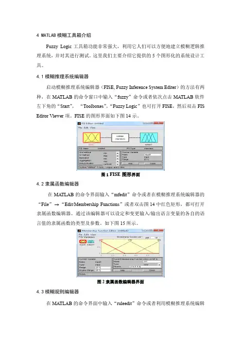
4.1模糊推理系统编辑器启动模糊推理系统编辑器(FISE, Fuzzy Inference System Editer)的方法有两种,在MATLAB的命令窗口中输入“fuzzy”命令或者依次点击MATLAB软件左下角的“Start”,“Toolboxes”,“Fuzzy Logic”也可打开FISE,然后双击FIS Editor Viewer项。
FISE的图形界面如下图14示。
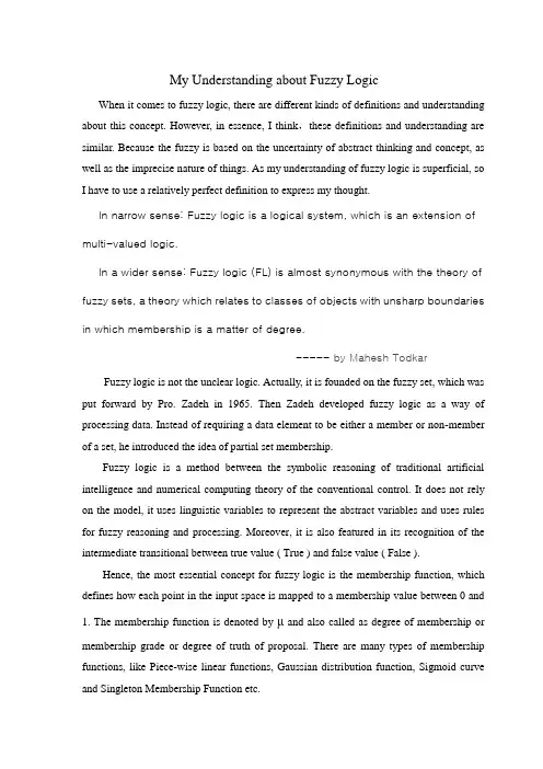
图1FISE图形界面4.2隶属函数编辑器在MATLAB的命令界面输入“mfedit”命令或者在模糊推理系统编辑器的“File” “Edit/Membership Functions”或者双击图14中红色矩形,都可打开隶属函数编辑器。
通过该编辑器可以设定和变更输入/输出语言变量的各自的语言值的隶属函数的类型及参数。
如下图15所示。
图2隶属函数编辑器界面4.3模糊规则编辑器在MATLAB的命令界面中输入“ruleedit”命令或者利用模糊推理系统编辑器的“File” “Edit/Rules”或双击图2里红色框旁的黑色的矩形框,都可以打开模糊规则编辑器。
通过该编辑器可以添加、修改和删除必要的模糊规则,其空白界面如下图3所示。
图3模糊规则编辑器界面4.4模糊规则观察器在MATLAB的命令界面输入“ruleview”命令,或者在前面介绍的三种编辑器中的任一个中选择相应的“View/Rules”,均可打开模糊规则观察器。
在模糊规则观察器中,以图形形式描述了模糊推理系统的推理过程,如下图4所示。
图4模糊规则浏览器界面4.5模糊推理输入输出变量特性观察器在MATLAB的命令窗口中输入“surfview”命令,或者在各个编辑器窗口选择相应菜单“View/Surface”,都可打开模糊推理输入输出曲面浏览器。
My Understanding about Fuzzy LogicWhen it comes to fuzzy logic, there are different kinds of definitions and understanding about this concept. However, in essence, I think,these definitions and understanding are similar. Because the fuzzy is based on the uncertainty of abstract thinking and concept, as well as the imprecise nature of things. As my understanding of fuzzy logic is superficial, so I have to use a relatively perfect definition to express my thought.In narrow sense: Fuzzy logic is a logical system, which is an extension of multi-valued logic.In a wider sense: Fuzzy logic (FL) is almost synonymous with the theory of fuzzy sets, a theory which relates to classes of objects with unsharp boundaries in which membership is a matter of degree.----- by Mahesh Todkar Fuzzy logic is not the unclear logic. Actually, it is founded on the fuzzy set, which was put forward by Pro. Zadeh in 1965. Then Zadeh developed fuzzy logic as a way of processing data. Instead of requiring a data element to be either a member or non-member of a set, he introduced the idea of partial set membership.Fuzzy logic is a method between the symbolic reasoning of traditional artificial intelligence and numerical computing theory of the conventional control. It does not rely on the model, it uses linguistic variables to represent the abstract variables and uses rules for fuzzy reasoning and processing. Moreover, it is also featured in its recognition of the intermediate transitional between true value ( True ) and false value ( False ).Hence, the most essential concept for fuzzy logic is the membership function, which defines how each point in the input space is mapped to a membership value between 0 and 1. The membership function is denoted by μ and also called as degree of membership or membership grade or degree of truth of proposal. There are many types of membership functions, like Piece-wise linear functions, Gaussian distribution function, Sigmoid curve and Singleton Membership Function etc.In addition, we should pay the major attention to the fuzzy inference, which is the process of formulating the mapping from a given input to an output using fuzzy logic.It involves Membership Functions (MF), Logical Operators and If-Then Rules. The MF is mentioned above, so an introduction about Logical Operators and If-Then Rules will be presented as followed.Fuzzy Logic Operators are used to write logic combinations between fuzzy notions.As for Zadeh operators, its definitions are :1)Intersection: μ(A AND B) = MIN(μ(A), μ(B))2)Union: μ(A OR B) = MAX(μ(A), μ(B))3)Negation: μ(NOT A) = 1 -μ(A)Fuzzy If-Then Rules are the statements used to formulate the conditional statements that comprise fuzzy logic. For example:if x is A then y is Bwhere,A &B – Linguistic values x – Element of Fuzzy set X y – Element of Fuzzy set YIn above example,Antecedent (or Premise)– if part of rule (i.e. x is A)Consequent (or Conclusion) – then part of rule (i.e. y is B)Here, interpreting if-then rule is a three–part process:1) Fuzzify input:Resolve all fuzzy statements in the antecedent to a degree of membership between 0 and 1.2) Apply fuzzy logic operator to multiple part antecedents:If there are multiple parts to the antecedent, apply fuzzy logic operators and resolve the antecedent to a single number between 0 and 1.3) Apply implication method:The output fuzzy sets for each rule are aggregated into a single output fuzzy set. Then the resulting output fuzzy set is defuzzified, or resolved to a single number.In general, from my perspective, compared with conventional binary logic, fuzzy logic is a breakthrough for the classification of things. To some degree, fuzzy logic makes the uncertainty and imprecision clearer. Though the membership functions vary from person to person, which indicates that fuzzy logic is subjective, its advantages are explicit. Just asMr. Hu Baoqing(from Wuhan University) notes that Benefits of Fuzzy Mathematics are:①The ability to model highly complex business problems②Improved cognitive modeling of expert system③The ability to model systems involving multiple experts④Reduced model complexity⑤Improved handling of uncertainty and possibilities……。
ieee fuzzy 短文Fuzzy logic is a mathematical tool that allows for approximate reasoning and decision-making in uncertain or ambiguous situations. It originated from the work of Lotfi Zadeh in the 1960s and has since been widely applied in various fields, including engineering, computer science, and artificial intelligence.At its core, fuzzy logic deals with degrees of truth rather than the traditional binary logic of true or false. It acknowledges that many concepts in the real world are not easily defined or categorizable in a strict sense. Fuzzy logic allows for the representation of imprecise or vague information and enables the use of linguistic terms to describe these concepts.The main building blocks of fuzzy logic are fuzzy sets, which are defined by membership functions that assign a degree of membership to each element in a set. Unlike in classical set theory, where an element either belongs to a set or does not, fuzzy sets provide a more flexible approach by allowing for partial membership. This allows for a more nuanced representation of data and facilitates better decision-making in uncertain situations. Fuzzy logic is often employed in control systems, where it enables the modeling of complex, nonlinear relationships between inputs and outputs. By incorporating linguistic rules, fuzzy logic controllers can handle imprecise or incomplete information and adapt to changing conditions. This makes them particularly useful in applications such as temperature and speed control, as well as in intelligent systems like autonomous vehicles.Another area where fuzzy logic has found extensive application is in pattern recognition and image processing. Fuzzy logic algorithms can effectively handle the inherent uncertainty and variability in real-world data, making them suitable for tasks such as object recognition, classification, and clustering. By considering the degree of similarity or dissimilarity between objects, fuzzy logic techniques can provide more robust and reliable results compared to traditional binary methods.Fuzzy logic has also been utilized in decision-making systems, where it allows for the modeling of human-like reasoning processes. By employing fuzzy inference and rule-based systems, decision support systems can analyze complex data and make intelligent decisions based on expert knowledge and subjective criteria. This can be particularly valuable in fields such as medicine, finance, and risk analysis, where decisions often involve multiple factors and uncertainties.Despite its numerous applications and advantages, fuzzy logic does have its limitations. The construction of accurate membership functions and the formulation of appropriate fuzzy rules can be challenging. Additionally, the computational complexity of fuzzy logic algorithms may be higher compared to classical methods, leading to increased processing time and resource requirements.In conclusion, fuzzy logic provides a powerful framework for dealing with uncertainty and imprecision in decision-making. Its ability to handle vague and incomplete information makes it highly applicable in a wide range of fields. By incorporating linguistic terms and membership functions, fuzzy logic enables morerealistic and human-like reasoning processes. However, it is important to carefully consider the appropriate use of fuzzy logic and to address the associated challenges when applying it in practice.。
模糊控制考核论文姓名:郑鑫学号:1409814011 班级:149641 题目:模糊控制的理论与发展概述摘要模糊控制理论是以模糊数学为基础,用语言规则表示方法和先进的计算机技术,由模糊推理进行决策的一种高级控制策。
模糊控制作为以模糊集合论、模糊语言变量及模糊逻辑推理为基础的一种计算机数字控制,它已成为目前实现智能控制的一种重要而又有效的形式尤其是模糊控制和神经网络、遗传算法及混沌理论等新学科的融合,正在显示出其巨大的应用潜力。
实质上模糊控制是一种非线性控制,从属于智能控制的范畴。
模糊控制的一大特点是既具有系统化的理论,又有着大量实际应用背景。
本文简单介绍了模糊控制的概念及应用,详细介绍了模糊控制器的设计,其中包含模糊控制系统的原理、模糊控制器的分类及其设计元素。
关键词:模糊控制;模糊控制器;现状及展望Abstract Fuzzy control theory is based on fuzzy mathematics, using language rule representation and advanced computer technology, it is a high-level control strategy which can make decision by the fuzzy reasoning. Fuzzy control is a computer numerical contro which based fuzzy set theory, fuzzy linguistic variables and fuzzy logic, it has become the effective form of intelligent control especially in the form of fuzzy control and neural networks, genetic algorithms and chaos theory and other new integration of disciplines, which is showing its great potential. Fuzzy control is essentially a nonlinear control, and subordinates intelligent control areas. A major feature of fuzzy control is both a systematic theory and a large number of the application background.This article introduces simply the concept and application of fuzzy control and introduces detailly the design of the fuzzy controller. It contains the principles of fuzzy control system, the classification of fuzzy controller and its design elements.Key words: Fuzzy Control; Fuzzy Controller; Status and Prospects.引言传统的常规PID控制方式是根据被控制对象的数学模型建立,虽然它的控制精度可以很高,但对于多变量且具有强耦合性的时变系统表现出很大的误差。

模糊函数matlab模糊函数是什么?在Matlab中如何使用和分析模糊函数?摘要:模糊函数是一种利用模糊逻辑进行数据处理和推理的方法。
在Matlab中,我们可以使用Fuzzy Logic Toolbox提供的函数和工具来创建、分析和优化模糊函数。
本文将详细介绍如何在Matlab中使用和分析模糊函数的步骤。
一、什么是模糊函数?模糊函数是一种将模糊逻辑应用于数学和工程问题中的方法。
它通过将输入映射到一个隶属度函数,并使用模糊规则作为输入映射的依据来模拟人类的模糊推理过程。
模糊函数常用于处理模糊的、不确定的或模糊的输入和输出。
二、在Matlab中创建模糊函数的步骤:1. 导入Fuzzy Logic Toolbox:首先,我们需要确保已经导入了Matlab 的Fuzzy Logic Toolbox。
可以通过在命令窗口中输入"fuzzy"来检查是否已经导入。
2. 创建模糊系统:使用命令"fuzzysystem = newfis()"来创建一个新的模糊系统对象。
这将创建一个空的模糊系统,可以在其中定义输入、输出和模糊规则。
3. 定义输入和输出:使用命令"fuzzysystem = addvar(fuzzysystem,'input', [min max])"来定义输入。
可以指定输入的名称、最小值和最大值。
同样,使用命令"fuzzysystem = addvar(fuzzysystem, 'output', [min max])"来定义输出。
4. 定义隶属度函数:使用命令"fuzzysystem = addmf(fuzzysystem,'input', 'mf', [params])"来定义输入或输出的隶属度函数。
其中,'input'是输入或输出的名称,'mf'是隶属度函数的名称,[params]是隶属度函数的参数。
有关对模糊逻辑的几点哲学思考的探析中英文对照The analysis of the philosophical thoughts on fuzzy logic inChinese and English一、模糊逻辑的研究对象The object of study, a fuzzy logic欲弄清模糊逻辑的研究对象首先必须得清楚逻辑的研究对象,因为模糊逻辑只不过是在经典逻辑的基础之上发展起来的一门分支学科。
只要搞清楚了逻辑的研究对象,那么模糊To clarify the fuzzy logic object of study must first clearly the object of study of logic, because fuzzy logic is just a branch of development on the basis of classical logic. As long as the clear object of study of logic, then the fuzzy逻辑的研究对象也就容易理解了。
那么到底什么是逻辑的研究对象呢?对这个问题有着各式各样的回答。
“关于逻辑的对象,从大的方面说,可以分为以下几种观点:(1)逻辑是研The research object of logic is easy to understand. What is the object of logic? There is every kind of answer to this question. " The object of logic, in large part, can be divided into the following several points: ( 1 ) logic is.究思维的;(2)逻辑是研究客观世界的;(3)逻辑是研究语言的;(4)逻辑是研究推理形式的有效性的。
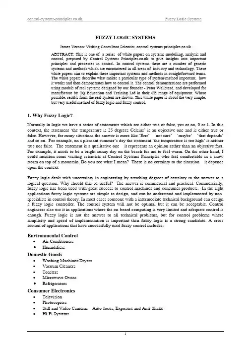
FUZZY LOGIC SYSTEMSJames Vernon: Visiting Consultant Scientist, control systems ABSTRACT: This is one of a series of white papers on systems modelling, analysis andcontrol, prepared by Control Systems to give insights into importantprinciples and processes in control. In control systems there are a number of genericsystems and methods which are encountered in all areas of industry and technology. Thesewhite papers aim to explain these important systems and methods in straightforward terms.The white papers describe what makes a particular type of system/method important, howit works and then demonstrates how to control it. The control demonstrations are performedusing models of real systems designed by our founder - Peter Wellstead, and developed formanufacture by TQ Education and Training Ltd in their CE range of equipment. Wherepossible, results from the real system are shown. This white paper is about the very simple,but very useful method of fuzzy logic and fuzzy control.1. Why Fuzzy Logic?Normally in logic we have a series of statements which are either true or false, yes or no, 0 or 1. In this context, the statement ‘the temperature is 25 degrees Celsius’ is an objective one and is either true or false. However, for many situations the answer is more like ‘Errr’ – ‘not sure’ – ‘maybe’ – ‘that depends’ and so on. For example, on a pleasant summer’s day the statement ‘the temperature is too high’ is neither true nor false. The statement is a qualitative one – it represents an opinion rather than an objective fact. For example, it needs to be a bright sunny day on the beach for me to feel warm. On the other hand, I could mention some visiting scientists at Control Systems Principles who feel comfortable in a snow storm on top of a mountain. Do you see what I mean? There is no certainty to the situation – it depends upon the context.Fuzzy logic deals with uncertainty in engineering by attaching degrees of certainty to the answer to a logical question. Why should this be useful? The answer is commercial and practical. Commercially, fuzzy logic has been used with great success to control machines and consumer products. In the right applications fuzzy logic systems are simple to design, and can be understood and implemented by non-specialists in control theory. In most cases someone with a intermediate technical background can design a fuzzy logic controller. The control system will not be optimal but it can be acceptable. Control engineers also use it in applications where the on-board computing is very limited and adequate control is enough. Fuzzy logic is not the answer to all technical problems, but for control problems where simplicity and speed of implementation is important then fuzzy logic is a strong candidate. A cross section of applications that have successfully used fuzzy control includes:Environmental Control• Air Conditioners• HumidifiersDomestic Goods• Washing Machines/Dryers• Vacuum Cleaners• Toasters• Microwave Ovens• RefrigeratorsConsumer Electronics• Television• Photocopiers• Still and Video Cameras – Auto-focus, Exposure and Anti-Shake• Hi-Fi SystemsAutomotive Systems•Vehicle Climate Control •Automatic Gearboxes •Four – Wheel Steering • Seat/Mirror Control SystemsThis is an impressive list, and gives an idea of the key application areas. In general you will not find a fuzzy controller in a safety critical application, unless the practical and theoretical performance has been completely studied.2. Engineering MotivationA traditional logic decision block produces an outcome based upon binary logic. A firm YES or NO emerges as an output of the decision block. However, the inventor of fuzzy logic, Lofi Zadeh, noted that human decision making incorporates shades of meaning in which the binary YES/NO might be replaced by:DEFINITELY YES,PROBABLY YES,MAYBE,PROBABLY NO,DEFINITELY NO.Fuzzy logic copies this feature of human decision making using levels of possibility in a number of uncertain (or fuzzy) categories. For example, think about the Coupled Tanks System (See Elke’s white paper on Coupled Tanks Systems on the download page of for full details) in which the object is to adjust the input voltage, u, to the pump motor (Figure 1) so that the level in Tank 2 is held at a steady value. The measured output is the level in Tank 2, denoted by the signal . My colleague Elke would apply a PI controller to this system as fast you could say ‘the hills are alive with the Sound of Music’. But if the 2y exact level is not important then why not use a simpler controller? For example, a common sense controller could use the following fuzzy control rules:IF {level too high} THEN {reduce pump voltage}IF {level too low} THEN {increase pump voltage}IF {level correct} THEN {set pump voltage zero}The controller performance would not be as good as a PI controller, but it might be acceptable – and that is what we are after – the simplest and cheapest possible controller for a given application. Sorry about that Elke.Figure 1. Coupled Tanks System3. How to Do Fuzzy Logic3.1. Classification - Turning a Real Signal into a Set of Fuzzy VariablesThe first step in fuzzy logic is to convert the measured signal x (which might be the error signal in a control system) into a set of fuzzy variables. This is called fuzzy classification or fuzzification . It is done by giving values (these will be our fuzzy variables) to each of a set of membership functions. The values for each membership function are labelled µ(x), and are determined by the original measured signal x and the shapes of the membership functions. A common fuzzy classifier splits the signal x into five fuzzy levels as follows:-a) LP: x is large positiveb) MP: x is medium positivec) S: x is smalld) MN: x is medium negative e) LN: x is large negativeMembership functions for three of these five fuzzy levels are shown in Figures 2a. So, for example, the value (or fuzzy variable) for the MP membership function and a signal value of is 2.5v x =5.0)5.2(=mp µ.Figure 2a. Membership Functions for Zero Membership (S: x is small), Medium PositiveMembership (MP), Large Positive Membership (LP).Figure 2a only shows the zero (or small S), medium positive (MP), and large positive (LP) memberships. The remaining two (MN, LN) are the same as the MP and LP shapes, but with the x axis reversed. Figure 2b shows all five membership functions on the same axis.Figure 2b. The Complete Set of Membership Functions for Five Level FuzzificationThe shape of the membership functions in Figures 2a and 2b is termed ‘triangular’ – this is only one of many choices of membership function shapes. I use triangular shapes because they are widely used, simple to implement and give good results.A practical fuzzifier would have a measured signal from a sensor at its input and would provide at its output the values (fuzzy variables) corresponding to the membership functions. For example, if a sensor signal with an output voltage of 2V is applied to a five level fuzzifier, the resulting set of fuzzy variables is:4.06.00LN =====LP MP S MN µµµµµAs the input to the fuzzifier changes in the range –10v to +10v, then the corresponding fuzzy variables will also change.In a controller the fuzzifier is used to determine the level of membership by connecting a measured signal from the system to the fuzzifier input. For example, if the five level fuzzifier is connected to the Coupled Tanks System, then the membership value associated with a statement like: "the level in Tank 2 is large positive " is obtained by connecting the signal for level in Tank 2 () to the input of the fuzzifier and monitoring the LP output of the classifier as in Figure 3.2yFigure 3. Measuring the Membership Value ‘Level 2 is Large and Positive’.3.2. Fuzzy Decisions BlocksFuzzy control uses fuzzy equivalents of logical AND, OR and NOT operations to build up fuzzy logic rules. The definitions of these are: AND : If αµ is the membership of class α for a measured variable βµand is the membership of class β for another measured variable, then the fuzzy AND is obtained as the minimum of the two membership values:),min(A βµαµβηαµβαµ=∧=ND Where the symbol ∧ is used to denote the fuzzy AND operation. An alternative definition of the fuzzy AND is that is the product of the two membership values:βµαµβµαµβαµ×=∧=ND A We have used both in practical applications and there is not much difference, so I generally recommend the first definition of fuzzy AND. OR : The previously given definitions of βαµµ apply again, and the fuzzy OR function is defined as:),max(βµβµβµαµβαµ=∨=OR NOT : For membership αµ the fuzzy NOT operation is defined by: αµαµαµ−=¬=1NOT Where the symbol ¬ is used to denote the fuzzy NOT operation.3.3. Defuzzification - Turning a Set of Fuzzy Variables into a Real SignalThe last step in building a fuzzy logic system is turning the fuzzy variables generated by the fuzzy logic rules into a real signal again. The fuzzy logic process which does this is called defuzzification because it combines the fuzzy variables to give a corresponding real (crisp or non-fuzzy) signal which can then be used to perform some action. For example, in the case of a coupled tanks control system the crisp signal would be a voltage which can be used to actuate the pump drive amplifier.A five level defuzzifier block (Figure 4) will have inputs corresponding to the following five actions:a) LP: Output signal large (positive)b) MP: Output medium (positive)c) S: Output signal smalld) MN: Output signal medium (negative) e) LN: Output signal large (negative)Figure 4. Block Diagram of a DefuzzifierThe defuzzifier combines the information in the fuzzy inputs to obtain a single crisp (non-fuzzy) output variable. There are a number of ways of doing. This is the simplest and most widely used method and is called the centre of Gravity Method. It works as like this: If the fuzzy levels LP......LN have membership values that are labelled µ1.....µ5, then the crisp output signal u is defined as:-∑∑===5151i i i i iu u µµWhere the values of the are, i u V - V, u -V, u V, u V, u u 105051054321=====, and correspond to the central points of the fuzzy classes LP: MP: S: MN: LN at the input to the defuzzifier. Defuzzifier input terminals which have no connections have fuzzy input values of zero.4. Developing Fuzzy Logic Control RulesMany research papers have been written on how to create fuzzy rule sets. Most of these methods are mathematical and require analytical knowledge to understand them. In our view this defeats the purpose of fuzzy logic. The main motivation for fuzzy logic is that by simply writing down common sense rules it is possible to build a reasonable control strategy without deep theoretical knowledge of control. This means that we will have no knowledge of the stability properties of the controller, and so the scope of applications is restricted to fairly simple control applications. This is fine because there are simple control problems that just want a simple solution. I have mentioned already the domestic products market, but we can add to this some of the simpler industrial control loops.A fuzzy control system is obtained by writing a set of rules of the form:IF {situation} THEN {action}The procedure is to write down the basis rules and add and refine them based upon experience. In the example of the coupled tanks system, a fuzzy rule which forms part of a control system might be: IF {error small} AND {control signal large positive}THEN {control signal small} (#1)The fuzzy levels 'error small' and 'control signal large positive' would be obtained by using the error, e, and control signal, u, as input signals to two separate five level fuzzifiers and selecting outputs S and LP respectively. The fuzzy levels are then fed through a fuzzy AND block to obtain a fuzzy value that gives the membership value corresponding to the situation. A fuzzy system which implements the fuzzy control rule #1 is shown in Figure 5.Figure 5. An Implementation of Fuzzy Rule #1In most fuzzy logic control systems the set of fuzzy actions is a simple list of rules for an open loop sequence. An example of an open loop fuzzy control sequence is that which might be used in a washing machine water heater control where water temperature is not really critical. In a simplified version of a wash cycle the washing machine design engineer may wish to begin the wash with maximum heater power and gradually reduce the power as the wash-cycle time increases, ending with zero power at the completion of the wash cycle. A fuzzy rule set for this control cycle is:-IF {cycle-time small} THEN {heater power large positive}IF {cycle-time medium positive} THEN {heater power medium positive}IF {cycle-time large positive} THEN {heater power small}Notice that the rules in this fuzzy control sequence are such that they can be simply written down and sequentially implemented in software using the fuzzy blocks described previously. The fuzzy rule set becomes more complex if the fuzzy level state associated with more than one signal must be accounted for. In such cases the rules contain interactions such that the fuzzy AND/OR of two or more fuzzy variables might be required. For example, consider again the washing machine control cycle in which the designer wants to become more sophisticated by taking account of the water temperature. Specifically, suppose that the designer wants to prevent the wash temperature becoming high, then the third rule could be changed to:IF {cycle-time large positive} OR {water temperature large positive} THEN {heater power small}The use of the fuzzy OR means that a more complex control cycle is created in which the heater power is reduced if the temperature gets too high as well as at the end of the wash.From the above simple example, you can see how we put together fuzzy rules and add to them as and when new needs appear. In some cases the set of fuzzy rules can get long and hard to follow. In these cases fuzzy state tables are sometimes used. These are logic tables that enable a large set of fuzzy AND statements to be compressed into simple tabular form. The CE124 Fuzzy Logic System which is described below, uses a state table for this reason.5. Fuzzy Control in Feedback SystemsThe most suitable applications for fuzzy control are where there are qualitative requirements for a satisfactory control action and these qualitative requirements can be easily stated as fuzzy logic rules. For this reason, fuzzy logic controllers are used to operate the automatic functions of washing machines, video recorders, compact disk players, air conditioning systems, cameras and similar products. It is also possible to find fuzzy logic in industrial feedback control that is normally done by experienced human operators who have manual control over a complex process. The procedure followed is to put the operator’s control procedure into a fuzzy rule set and hence develop a fuzzy control system. The fuzzy logic designer copies the heuristic actions of a human operator when they control a process and writes down the corresponding fuzzy rule. By careful observations of a skilled operator, a complete set of fuzzy rules is obtained which can reproduce the best performance of the human operator. The result is an "intelligent" control system that is obtained without reference to control systems theory but contains the knowledge of a good human operator. There was great enthusiasm for this approach in the 1970 and 1980 period, but it was found that the human operator can not be easily replaced and now such fuzzy systems are used as an advisor to the operator – the idea is to improve safety rather than replace the operator.A popular application of fuzzy logic is the control of simple loops usually controlled using three term (PID) controllers. The fuzzy logic copies the PID action with some modifications to handle non-linear plant behaviour. Figure 6 shows how a fuzzy logic system might replace a conventional controller.Figure 6. The Fuzzy Controller and its Relation to a Conventional Control LoopThe procedure adopted in fuzzy control is to imitate the actions of a traditional controller using fuzzy rules and add features to deal especially with special system features such as nonlinearities.5.1. Fuzzy Proportional ControlA very simple fuzzy version of proportional controller isRule 1: IF {error LN} THEN {control LN}Rule 2: IF {error MN} THEN {control MN}Rule 3: IF {error S} THEN {control S}Rule 4: IF {error MP} THEN {control MP}Rule 5: IF {error LP} THEN {control LP}In fact this rule set produces exactly the same linear control action as a controller with proportional control and a gain of one, operating on the error signal. This brings no advantage at all. However, the gain of the controller can be made non-linear by changing the fuzzy rules, and this can be useful in special applications. To give a simple example, consider the case of the Coupled Tanks System, where the input pump cannot be driven backwards to suck water out of the tank (e.g. the minimum control input is 0V) and the pump input signal amplifier will not accept more than a maximum of 10V. These practical limits on the working range of a control systems actuator are normal, and it is easy to adapt a fuzzy controller to account for them. A fuzzy proportional controller which incorporates the constraint that the minimum input signal is 0V is:-Rule 1: IF {error LN} OR {error MN} OR {error S} THEN {control S}Rule 2: IF {error MP} THEN {control MP}Rule 3: IF {error LP} THEN {control LP}Here the level S is 0v and Rule 1 ensures that the pump does not receive negative signals. Figure 7 is an implementation of this rule set F uzz ifierDefuz z ifier Control u(t)OR E rrore(t)y(t)r(t)+-S L P L P MP MP SS MNMN L N L N Figure 7. Implementation of Fuzzy Rule Set RS4This is a simple demonstration. With more complex fuzzy rules complex non-linearities can be achieved. Many control professionals will question whether this is the correct way to design a non-linear controller, however practical engineers sometimes do this where they are sure of the stability implications.5.2. Proportional Plus Derivative Fuzzy ControlThe fuzzy proportional controller can be extended easily to cover integral action and derivative control. Here we outline just the derivative control extension. In this case the fuzzy logic controller operates on the error signal e(t) and the derivative of the output signal dtt dy )( and produces an output from its defuzzifier which is the control signal u(t). (See Elke’s excellent white paper on three term control on the download page of to understand why the derivative of the output, and not the derivative of the error, is used). The fuzzy logic controller bases its actions on the two signals:- the error and the rate of change of output. In this context, it is important to notice that the fuzzy controller does not contain any dynamic elements. All dynamic components are outside the controller and are obtained by direct measurement from the system or by signal processing of the system input and output signals The output derivative is either available as a direct measurement from the system or by using an observer of the system states.After fuzzification of the error and the output rate, fuzzy rules are applied to the fuzzifier variables. The role of rate feedback in a conventional controller is to reduce the control action if the output is changing too rapidly, this reduces the possibility of the output overshooting the desired reference value, r(t). Using this principle, fuzzy rules can be written which help to avoid such occurrences. For example, the rule set given below has the first five rules providing fuzzy proportional control. The Rules 6 and 7 try tocompensate for rapid changes when the error is small by providing a component of the control which will decrease the rate of change of the system output.Rule 1: IF {error LP} THEN {control LP}Rule 2: IF {error MP} THEN {control MP}Rule 3: IF {error S } THEN {control S}Rule 4: IF {error MN} THEN {control MN}Rule 5: IF {error LN} THEN {control LN}Rule 6: IF {error S} AND {output_rate LP } THEN {control LN}Rule 7: IF {error S} AND {output_rate LN } THEN {control LP}This rule set approximates proportional plus derivative control action, but only when the error is small. By studying a conventional linear controller with rate feedback it is possible to form rule sets which imitate them. For example the conventional proportional plus derivative control law is:dtt dy k t e k t u d p )()()(−= Where is the proportional gain and is the derivative feedback gain. From this equation it is possible to deduce a simple set of equivalent fuzzy rules:p k d k Rule 1: IF {error N} AND {rate P} THEN {control N}Rule 2: IF {error N} AND {rate N} THEN {control S}Rule 3: IF {error P} AND {rate N} THEN {control P}Rule 4: IF {error P} AND {rate P} THEN {control S}The fuzzy control corresponding to this rule set is a very coarse approximation to the behaviour of a controller with proportional plus derivative action. With these four rules, the quality of control achieved would be poor. In order to see this, Figure 8 shows an isometric view of the control signal plotted as a function of the error and rate. Notice that the control action moves only between three levels +10V, 0V and -10V. The poor results of this rule set can be improved by adding more levels of fuzzification to achieve a closer approximation to the true control law. For example, Figure 9 shows the control surface corresponding to five levels of fuzzification in the control rule.Figure 8. Isometric Plot of Control-Rate Signal for a Three Level Fuzzy ControllerFigure 9. Isometric Plot of Control-Rate Signal for a Five Level Fuzzy ControllerThe addition of the extra levels of classification give a much smoother control surface and by increasing the number of fuzzification levels yet further, a much closer approximation can be obtained. However it is not the purpose of fuzzy control to emulate conventional control – and I only include these results as a demonstration. Fuzzy control is at its best when used on simple systems (e.g. the domestic products I that have I mentioned earlier in this white paper), or where a nonlinear feature of the system can be compensated for easily in a set of special fuzzy control rules.6. Fuzzy Logic Systems.There are a number of fuzzy logic systems available, and the fuzzy logic system shown in Figure 10 is typical of these systems. It is laid out as a schemmatic of a fuzzy system would be, with two fuzzifiers on the left of the panel (above and below the TQ logo), a fuzzy state table at the top centre, and set of fuzzy logic AND, OR and NOT blocks (again in the centre), and a defuzzifier at the right hand side.Figure 10. The CE124 Fuzzy Logic SystemThe system shown in Figure 10 is especially designed to allow users to quickly implement fuzzy logic systems in an intuitive way. Because the fuzzy logic components are separately represented, it is easy to connect up fuzzy rules from a block diagram and then to track the variations in fuzzy signals (using built in ‘fuzzy meters’) through the logic system. This is very important and useful during development and testing on real hardware. Specifically, the developer can measure the ways in which the membership functions vary over time and so check that fuzzy rules are actually doing what they are meant to do. Rewiring the fuzzy logic system is quick and easy, so that a fuzzy control system can be rapidly tested and improved on-line. For the same reasons, the CE124 is also a good learning tool. I have found that people who initially find fuzzy logic concepts difficult are able to understand the technique after a session with the CE124 hardware.The CE124 has hardware and software options for fuzzy logic development. This contrasts with the other main family of fuzzy logic systems that are software packages and often require Matlab and Matlab Toolboxes to operate. Software packages can be very powerful tools and contain many advanced fuzzy system features. They are however usually simulation tools so that practical implementation is harder to acheive7. A Final WordI hope that you have got some ideas about the background and uses of fuzzy control from this white paper. We get lots of inquires for help and and advice on projects and applications, but the usual disclaimer applies - I am sorry to say that it is not possible to answer general questions about the contents of our white papers, unless we have a contract with your organisation. Control Systems Principles is a ‘tight ship’ and we do not have spare time for this kind of good will help. For more information about fuzzy control and the CE124 Fuzzy Logic System go to the TQ Education and Training web site using the links on our web site or use the email info@. Process level control and the Coupled Tanks system is also the download page of the Control Systems Principles web site, so do check that out.I have worked on practical fuzzy control systems for some time and this white paper contains the most useful parts of my ‘fuzzy know-how’. If you want to know more about fuzzy systems, then there are many detail research papers and text books on fuzzy control, but I recommend that you start with the original papers by Lofti Zadeh. Fuzzy logic has been a fashionable playground among many researchers, so be selective in your reading. On the other hand, Japanese engineers and researchers have taken fuzzy logic seriously – so fuzzy logic applications from Japanese companies should be read carefully as they always relevant and often informative.。

模糊控制介绍附件:一、模糊控制概况模糊逻辑控制(Fuzzy Logic Control)简称模糊控制(Fuzzy Control),是以模糊集合论、模糊语言变量和模糊逻辑推理为基础的一种计算机数字控制技术。
1965年,美国的L.A.Zadeh创立了模糊集合论;1973年他给出了模糊逻辑控制的定义和相关的定理。
1974年,英国的E.H.Mamdani 首先用模糊控制语句组成模糊控制器,并把它应用于锅炉和蒸汽机的控制,在实验室获得成功。
这一开拓性的工作标志着模糊控制论的诞生。
模糊控制实质上是一种非线性控制,从属于智能控制的范畴。
模糊控制的一大特点是既具有系统化的理论,又有着大量实际应用背景。
模糊控制的发展最初在西方遇到了较大的阻力;然而在东方尤其是在日本,却得到了迅速而广泛的推广应用。
近20多年来,模糊控制不论从理论上还是技术上都有了长足的进步,成为自动控制领域中一个非常活跃而又硕果累累的分支。
其典型应用的例子涉及生产和生活的许多方面,例如在家用电器设备中有模糊洗衣机、空调、微波炉、吸尘器、照相机和摄录机等;在工业控制领域中有水净化处理、发酵过程、化学反应釜、水泥窑炉等的模糊控制;在专用系统和其它方面有地铁靠站停车、汽车驾驶、电梯、自动扶梯、蒸汽引擎以及机器人的模糊控制等。
二、模糊控制基础模糊控制的基本思想是利用计算机来实现人的控制经验,而这些经验多是用语言表达的具有相当模糊性的控制规则。
模糊控制器(Fuzzy Controller,即FC)获得巨大成功的主要原因在于它具有如下一些突出特点:模糊控制是一种基于规则的控制。
它直接采用语言型控制规则,出发点是现场操作人员的控制经验或相关专家的知识,在设计中不需要建立被控对象的精确数学模型,因而使得控制机理和策略易于接受与理解,设计简单,便于应用。
由工业过程的定性认识出发,比较容易建立语言控制规则,因而模糊控制对那些数学模型难以获取、动态特性不易掌握或变化非常显著的对象非常适用。
Daily CollectionSmart 3D heatingBakuhanseki coatingMultifunction1.8LHD4515/85Great tasty rice and dishes for all the familyWith “Smart 3D” and long lasting BakuhansekiSmart 3D" creates powerful heat circulation from top, side and bottom that heatsrice evenly and thoroughly, together with the long loasting Bakuhanseki coatinginner pot makes great tasty rice and dishes for every mealMultiple functions10 dedicated cooking menus for the contemporary cook48 hours keep warm to keep rice and dishes fresh and tastyDurable inner pot5 layers for better heat conductivityBakuhanseki coating which is more durableEase of useDetachable inner lid for easy cleaningLarge digital display provides easy-to-read menus and timeSmart 3DSmartly adjust heating temperature for different programsSuper strong power that heats rice evenly and thoroughlyFuzzy Logic Rice CookerHD4515/85HighlightsSpecifications10 menus10 multifunction programs with separate menus for rice, multigrain and beans for a variety of dishes.48 hours keep warm48 hours keep warm to keep rice and dishes fresh and tasty5 layers5 layers for better heat conductivityBakuhanseki coatingBakuhanseki coating which is more durableDetachable inner lidAluminum alloy inner lid can be detached and cleaned to prevent the buildup of dirt and bacteriaLarge digital dispalyLarge digital display provides easy-to-read menus and time for easy operation.adjust heating temperatureSmartly adjust heating temperature for different programsSuper strong powerSuper strong power that heats rice evenly and thoroughlyAccessoriesIncluded: Measuring cup, Spatula, Steaming tray/basketGeneral specificationsProduct features: Preset cooking function,Time controlKeep warm function: 48 hour(s)Prefix programs: 10Type of lid: FixedT echnical specifications Cord length: 1.0 m Frequency: 50/60 Hz Voltage: 220 V Power: 400 WDesignColor of control panel: Dark beluga Color: WhiteFinishingMaterial of main body: PlasticService2-year worldwide guarantee Country of origin Made in: ChinaSustainabilityPackaging: > 90% recycled materials User manual: 100% recycled paper© 2021 Koninklijke Philips N.V .All Rights reserved.Specifications are subject to change without notice. Trademarks are the property of Koninklijke Philips N.V . or their respective owners.Issue date 2021‑03‑11Version: 1.0.1。
模糊神经和模糊聚类的MATLAB实现模糊神经网络(Fuzzy Neural Networks)是一种结合了模糊逻辑和神经网络的方法,用于处理不确定性和模糊性问题。
它具有模糊逻辑的灵活性和神经网络的学习和优化能力。
在MATLAB中,可以使用Fuzzy Logic Toolbox来实现模糊神经网络。
下面将介绍如何使用MATLAB实现模糊神经网络。
首先,我们需要定义输入和输出的模糊集合。
可以使用Fuzzy Logic Toolbox提供的各种方法来定义模糊集合的隶属函数,例如使用trimf定义三角隶属函数或者使用gaussmf定义高斯隶属函数。
```input1 = trimf(inputRange, [a1, b1, c1]);input2 = gaussmf(inputRange, [mean, sigma]);output = trapmf(outputRange, [d1, e1, f1, g1]);```接下来,可以使用FIS Editor界面来创建和训练模糊神经网络。
在MATLAB命令窗口中输入fuzzy命令即可打开FIS Editor界面。
在FIS Editor界面中,可以添加输入和输出变量,并设置它们的隶属函数。
然后,可以添加规则来定义输入与输出之间的关系。
规则的形式可以使用自然语言或者模糊规则表达式(Fuzzy Rule Expression)。
训练模糊神经网络可以使用基于模糊神经网络的系统识别方法。
在MATLAB中,可以使用anfis函数来进行自适应网络训练。
anfis函数可以根据训练数据自动调整隶属函数参数和规则权重,以优化模糊神经网络的性能。
```fis = anfis(trainingData);```使用trainfis命令可以将训练好的模糊神经网络应用于新的数据。
trainfis命令将输入数据映射到输出模糊集中,并使用模糊推理进行预测。
输出结果是一个模糊集,可以使用defuzz命令对其进行模糊化。
模糊控制算法的英文English:"Fuzzy control algorithm is a type of control system that uses fuzzy logic instead of precise values to manage the system. In this approach, linguistic variables are used to represent input and output values, and rules are defined using linguistic conditional statements. Fuzzy logic allows for a more flexible and human-like approach to control, particularly in systems where precise mathematical modeling is challenging or impossible. The key components of a fuzzy control system include fuzzification (converting crisp inputs into fuzzy sets), rule evaluation (applying fuzzy rules to determine output fuzzy sets), and defuzzification (translating fuzzy outputs into crisp values). Fuzzy control has been applied successfully in various fields such as industrial automation, consumer electronics, and automotive systems, where it can handle complex and uncertain environments effectively. It provides a way to incorporate expert knowledge and heuristics into control systems, enabling robust performance under changing conditions or incomplete information."中文翻译:"模糊控制算法是一种使用模糊逻辑而不是精确值来管理系统的控制系统类型。
Fuzzy Rules-based Classification for ChurnPredictionBingquan Huang,Ying Huang,and M-T.KechadiSchool of Computer Science and Informatics,University College Dublin,Belfield,Dublin4,Irelandbingquan.huang@ucd.ieying.huang.1@ucdconnect.ieAbstract.The customer churn influences the revenue and becomes aserious problem for a service company.In order to retain the valuablecustomers,rule-based classification methods which can transparently in-terpret the prediction results,have been prefered to use for the analysisof customer behaviour.However,due to the imbalanced distribution ofclasses(churn and nonchurn)with the high dimensional features,mostof the traditional rule-based methods may hard obtain acceptable pre-diction accuracy.This paper proposes a new fuzzy-rule-based modellingtechnique for churn prediction.Generally,the new prediction techniqueheuristically discoveries a set of fuzzy rules,then uses this set of rules toclassify the unkown observation objects.Finally,the experiments werecarried out to evaluate the proposed modelling technique,based on5datasets from UCI(University of California,Irvine)repository,and1dataset of telecommunication.The experimental results show that theproposed approach can achieve acceptable prediction accuracy and out-performs the existing rule-based methods.Keywords:Classification,Fuzzy Rules,Hill-climbing Search,High Or-der Rules1IntroductionService companies in telecommunications suffer from a loss of valuable customers to competitors;this is known as customer churn.In the last a few years,there have been many changes in the telecommunication industry,such as,new ser-vices,technologies and the liberalizations of the market increasing competition. Recently,data mining techniques have been emerged to tackle the challenging problem of customer churn in telecommunication servicefields[1,2,3,4].As one of the important measures to retain customers,churn prediction has been a concern in telecommunication industry and research.As one of the important phases in churn prediction process,classification can directly affect the prediction results.Many modelling techniques have been successfully used for the classification,including Decision Tree(DT),Logistic2Bingquan Huang,Ying Huang,M-T.KechadiRegression(LR),Artificial Neural Networks(ANN),Naive Bayes(NB)and Sup-port Vector Machine(SVM).However,they still have some limitations.Most of the modelling techniques provide either prediction probability or classification rules.For example,NB,LR[5,6,7],ANN[8,9]and SVM[10,11]can only provide the probability of classification,whereas they do not produce decision rules.DT [12,13,14]can produce rules,however,the probability of classification cannot be obtained from DT model[15].A number of Genetic Algorithm(GA)based classification models also have been reported in[16,17,18].These models can be efficient.However,they have high computational complexity.Recently,DMEL(Data Mining by Evolutionary Learning)[15],a GA based prediction approach was proposed.This technique not only provides classification rules,but also gives the probability of classifica-tion.It was shown that DMEL is a very promising modelling technique.This paper proposes a new classification method which is based upon fuzzy-rule induction.It can not only classify samples by a set of generated rules, but also it is able to produce the prediction probability.Besides,this approach is capable of dealing with high-dimension and imbalance data set.There are three main procedures for implementing the new algorithm:Firstly,normalizing all values of each attribute to a specified range,then fuzzy partitioning each attribute to several intervals.Secondly,generating rules by applying the heuristic of hill-climbing and pruning unimportant and redundant st but not least,predicting one of the categories to which a test case belongs according to the fuzzy rules.In the experiments,Lift Curve and AUC were applied to demonstrate the performance of algorithm.The rest of this paper is organized as follows:Section2introduces the re-lated work.Section3describes the details of the proposed algorithm.Section 4provides the experimental results and discussion.The conclusion and future work are given in Section5.2Related WorkRule-based classification is a well known domain.One of the main characteristics of rule induction is that they are more transparent and understandable than some other training models.A significant amount of research effort has been put into this domain.In a rule-induction process,usually two strategies are applied:general-to-specific(top-down)and specific-to-general(bottom-up).Due to that the strategy of general-to-specific is more widely applied in rule learning, this section will introduce several approaches by using it,besides examples of rule induction by applying the strategy of specific-to-general can be found in [19,20,21].Among all the different methods for constructing the rules,decision tree based algorithms are the most popular[12,13,14].C4.5has proved to be one of the most well known among all tree-based classifiers.A tree is constructed using the method of divide-and-conquer.C4.5starts to search an attribute with the highest information gain,and then the data is partitioned into classes accordingBingquan Huang,Ying Huang,M-T.Kechadi3 to this attribute.Each sub-tree represents a class,and will be recursively further partitioned using the same policy until some stopping criteria are satisfied,such as the leaf node has been reached etc.The rules can be obtained by traversing each branch of the tree.The details of this algorithm can be found in[12].CN2[22]works in an iterative way,each iteration searches one rule that covers(see section3.2for the definition)a large number of training cases by making use of beam search method.Entropy and likelihood ratio are used to evaluate the quality and the significance of the rules.Rules are ranked in accor-dance with the quality of rules.When classifying a test case,CN2goes through each rule untilfinding a rule that covers the case,then assigns the class label of that rule to the case.[23]describes a genetic-algorithm-based method for selecting a small number of significant fuzzy if-then rules to construct a compact classification system. The performance of this method is examined by computer simulation on the irish data set.This method generate a set of fuzzy rules and optimize rules by applying genetic algorithm,however,it is difficult to treat data sets with high-dimension attributes due to the expensive time complexity.DMEL is a genetic classification technique.The DMEL classifier consists of a set of labelled rules which were found by rule induction technique.DMEL starts by generating first−order rules,then high−order rules can be constructed iteratively by randomly combining lower order rules.Given a sample without labels,the DMEL classifier applies the rules to model the sample and makes the classification decisions.DMEL has been shown to be an efficient classifier.The details of this technique can be found in[15].3AlgorithmsAlthough experimental results from[15]showed that DMEL is efficient at detect-ing churners,there is still improvement that can be done for better classification accuracy.The objective in designing the new classification system is to improve the classification accuracy.The proposed approach does so by considering several aspects:Firstly,fuzzy logic technique was applied to partition each attribute into several interval;Secondly,it applies different heuristic methods for constructing classification rules;Thirdly,constraints were introduced to get rid of bad and redundant rules.3.1Fuzzy PartitionIn this section,we briefly talk about the partition for each attribute based on fuzzy logic.Fuzzy logic emerged as a consequence of the proposal of fuzzy set theory by LotfiZadeh[24]in1965.In contrast with Crisp Logic,which has a binary sets,fuzzy logic variables may have a value that ranges in degree between 0and1.The degree,which represents how much extent dose an attribute value belongs to a subset of fuzzy partition,is managed by a membership function,such as triangle,trapezoid and exponential etc.In this paper,the classical triangle is4Bingquan Huang,Ying Huang,M-T.Kechadiapplied as the membership function.Give a training set D={f1,...,f i,...,f n} where f i denote the i th attribute and n is the number of attributes in the whole feature space.Suppose each attribute in the feature space is partitioned into m fuzzy subsets S={s1,...,s i,...s m},s i represents the i th subset.The membership function is expressed as follows:µi=max{1−|xF−(i−1)|,0}(1)whereF=1m−1(2)Fig.1.An example of fuzzy partition for an attribute.Figure1shows an example of fuzzy partition for an attribute,the vertical axis represents the degrees of membership,and the horizontal axis represents the values of the attribute,each instance has a different attribute values that corresponds to a diverse degree of membership,the number of subsets was set to be5in this example.In order to generate rules based on the fuzzy partition of attributes,all attribute values in both the training and testing data set are supposed to be normalized to[0,1].3.2Basic ConceptsThe Rules are of the following form:IF antecedent THEN consequence,where antecedent describes a conjunction of a certain number of<attribute,interval> pair,and consequence denotes the class label.An example of rule is as follows: Rule example:If V1is s i and...and V i is s j and...and V e is s k then class= Class cBingquan Huang,Ying Huang,M-T.Kechadi 5let V i and e be the value of attribute f i and the total number of <attribute,interval >pair in the antecedent part.s i ,s j and s k could be any fuzzy subset of the attribute and Class c is one of the categories.The total degree of membership of the rules can be calculated by :T DM =µ1·...·µi ...·µe ;(3)where µi is the degree of membership which expresses the extent that V i belongs to s j .Another basic concept of rule induction is Cover ,which expresses the case that a sample satisfies the antecedent part of the rule.A rule Correctly Covers a sample when it correctly predicts the covered sample.The task of rule induction is to build a model by generating a set of rules,which either do or do not Cover cases.general rule and specific rule are two important ually,a rule with a smaller number of <attribute,interval >pairs in the antecedent part is more general than the one having more.The reverse case is more specific .most general occurs when the number of antecedent is 1,while most specific means the number of antecedent is the total number of attributes.Normally,the most specific rules should not be considered since they are too specific and not able to describe a relative big data space.3.3Rule LearningThe new prediction algorithm explores the strategy of general-to-specific,so it starts by generating the most general rules,first-order rules,then iteratively constructing higher-order rules based on the lower-order rules.Algorithm 1il-lustrates the process of learning rules.SET rules is the set of generated rules,k denotes the number of orders,and Max −num −order denotes the maximal number of orders.Algorithm 1New Algorithm(training data)1:SET rules ←φ;2:k ←1;3:SET rules ←F irst −order −rules (training data);4:while k <=Max −num −order do 5:high −order ←Higher −order −rules (lower −order −rules );6:SET rules ←SET rules high −order ;7:k ++;8:end while 9:return SET rules6Bingquan Huang,Ying Huang,M-T.KechadiFirst-order Fuzzy Rules Algorithm2illustrates the process of generating thefirst-order fuzzy rules.In order to avoid information loss,all possible com-binations of<attribute,subset>pair were taken into account.In Algorithm2, num−attribute,num−subset and num−class respectively denotes the number of attributes,the number of fuzzy subsets of the current attribute and the num-ber of different categories.Initially,the set of first−order−rule is empty,rule ijk expresses a rule having the form”IF f i is s j THEN Class k”,if Pruning(rule ijk) returns false,then rule ijk can be accepted as a useful rule(Rule pruning is described in section3.4).Algorithm2F irst−order−rules(training data)1:F irst−order−rules←φ;2:for i=1;i<=num−attribute;i++do3:for j=1;j<=num−subset;j++do4:for k=1;k<=num−class;k++do5:if P runing(rule ijk)returns false then6:F irst−order−rules←F irst−order−rulesrule ijk;7:end if8:end for9:end for10:end for11:return F irst−order−rulesHigh-order Rules Higher-order rules are iteratively constructed based on the previous set of lower-order rules.The second-order is grounded on the first−order, the third−order is based on the second−order.Generally,(n−1)−order rules are the base for the n−order rules.Algorithm3illustrates the procedure of constructing a set of high−order rules.Positive lower order rules,which have the positive prediction,and negative lower order rules,which reversely have the negative prediction,can be separately obtained from the lower−order−rules.In algorithm3,item is used to define a<attribute,subset>pair.positive−items consist of all exclusive items extracted from all positive rules.We generate negative-items in the same way.Each positive rule becomes more specific by using the hill−climbing strategy to add one item into the antecedent part of the current rule.Algorithm4describes the heuristic of hill−climbing for con-structing one high order rule.It will be discussed in detail.The rule pruning is also an important step for generating high−order rules.In order to reduce computation time,we get rid of rules having the same quality.Many methods can be used to assess the quality of rules.They either focus on the coverage or on the accuracy.However,a measure having the ability to make a good trade offbetween coverage and accuracy is more suited for rule learning.Therefore, Weighted Relative Accuracy(WRA)[25],which can be calculated by Eq.(4)isBingquan Huang,Ying Huang,M-T.Kechadi 7applied.W RA =Num −(a )Num −total ×(Num −(a,c )Num −(a )−Num −(c )Num −total )(4)where Num −(a )and Num −(c )represent the number of data cases that are cov-ered by the antecedent and the consequence of a rule,respectively.Num −(a,c )is the number of cases correctly covered by a rule,and Num −total denotes the total number of cases in the training set.Line 9expresses that only rules with exclusive quality can be added.Algorithm 3Higher −order −rules (a set of lower −order −rules )1:all −rules ←φ;2:positive −items ←get all exclusive items from positive −lower −order −rules ;3:negative −items ←get all exclusive items from negative −lower −order −rules ;4:accuracy −list ←φ;5:for i =1;i <=num −positive −rules ;i ++do 6:high −rule ←hill −climbing (positive i ,positive −item );7:if P runing (high −rule )returns false then 8:W RA i ←calculate the W eighted −Relative −Accuracy for high −rule ;9:if W RA i is not in the list of accuracy −list then 10:all −rules ←all −rules high −rule ;11:accuracy −list ←accuracy −list W RA i ;12:end if 13:end if 14:end for 15:do the same work to generate negative −rules ;16:all −rules ←all −rules negative −rules ;17:return all −rules ;Algorithm 4illustrates the process of generating one high −order rule.Let accuracy −list ,which is a list consisting of different WRA values,be empty in the beginning.Basically,one piece of high −order is based on one piece of lower −order rule and a new item ,which has been mentioned earlier.If the new item does not occur in the antecedent of the lower −order rule,then one −high −order can be built by combining one −lower −rule and the new item .Meanwhile,the WRA value of the newly built one −high −order is stored in the accuracy −list .This algorithm returns one of the high −order rules with the highest WAR value.3.4Pruning RulesThe number of generated rules can be huge,to make the classification effective,we must prune bad rules with insignificant or noisy information.Several criteria are used for pruning ually,χ2statistic test is used to test if there exists8Bingquan Huang,Ying Huang,M-T.KechadiAlgorithm 4hill −climbing (one −lower −rule ,all −low −items )1:accuracy −list ←φ;2:for i =1;i <=num −low −items ;i ++do 3:if one −lower −rule does not include item i then 4:one −high −rule ←combination of one −lower −rule and item i ;5:W RA i ←calculate W eighted −Relative −Accuracy for one −high −rule ;6:accuracy −list ←accuracy −list W RA i ;7:end if 8:end for 9:BEST ←one of high order rules having the highest WRA;10:return BESTstrong relative relationship between two attributes.In this paper,χ2,which can be calculated by Eq.(5),is applied to decide whether a rule is significant which means all the attributes occurring in antecedent part of the rule correlate to the consequence.χ2=(O −E )2E(5)where O and E are the observed and expected frequency,which can be expressed by Eq.(6):O =Num −(a,c )E =Num −(a )×Num −(c )Num −total (6)In addition to χ2,Support and Confidence are another two essential factors when deciding if a rule should be pruned or not.Support and Confidence can be calculated by Eq.(7).Support =Num −(a,c )Num −total Confidence =Num −(a,c )Num −(a )(7)Algorithm 5illustrates the pruning method.αis the critical value for χ2significance test,and it is set to be 3.84in this research.minS and minC are two threshold values,which define the minimal value of support and confidence,respectively.In this research,the minimum value of support and confidence were set to be 0.01and 0.5,respectively.A rule can be retained if it satisfies all the threshold values.3.5ClassificationThis section discusses how to classify cases based on a number of classification rules.Rules consist of two categories,churn and non −churn .Two prediction models can be built based on all churn rules and all non −churn rules,respec-tively.In order to estimate the importance of each rule,we rank rules in each model based on a set of principles,which are also used in [26]and can be de-scribed as follows:Bingquan Huang,Ying Huang,M-T.Kechadi9Algorithm5Pruning(rule)1:F lag←true;2:if chi-square statistics>αAND Support−rule>minS AND Confidence−rule> minC then3:F lag←false;4:end if5:return Flag;1.If confidence−1>confidence−2,then rule−1has higher priority thanrule−2;2.If confidence−1=confidence−2and support−1>support−2,then rule−1also has higher priority than rule−2;3.If confidence−1=confidence−2,support−1=support−2and rule−1ismore general than rule−2,then rule−1has higher priority than rule−2.After ranking,each rule has a position in each prediction model,one is more important than another rule if it has a better position than the other.We define the significance of each rule as follows:Sig−level=Num−rules−positionNum−rules×T DM(8)where Num−rules is the number of rules,position denotes the rule index of the ranked rule set,refer to Equation3for calculating T DM.Therefore,in a prediction model,the Sig−level of the most important rule is1×T DM,while that of the least important one is T DMNum−rules .To classify a case,finding all covered rules from the churn model and non−churn model,respec-tively,if the sum Sig−level of covered rules in churn model is greater than that of non−churn model,then assign churn to the case as the class label,otherwise, non−churn will be assigned.Apart from the mentioned two cases,if the current data case had the same sum Sig−level for churn model and non−churn,the majority class label should be assigned.Moreover,the imbalance data set is a big challenge for data mining tech-niques.Therefore,for data set with the characteristic of imbalance,a threshold, which is used to adjust the weight of majority and the minority class,is better to be applied.In order to obtain a proper threshold value,we set a list of real numbers that are in the range of[0.9,1],the numbers are iterative added by 0.01up to the maximum value1.The5-fold cross-validation is applied on the training set,recording an AUC value each time by using the proposed fuzzy-rule prediction approach,finally the appropriate threshold comes to the one which generated the maximum AUC.Therefore,when predicting an given instance, Equation8need to be replaced by the following one:Sig−level=Num−rules−positionNum−rules×T DM×threshold(9)10Bingquan Huang,Ying Huang,M-T.KechadiIn order to have the idea of which customers are more likely to churn,the new method scores each customer according to the sum of its Sig−level.If one is predicted to churn,then this customer is scored the sum of Sig−level of the churn model.Otherwise,the sum of Sig−level in non−churn model will be used to score that individual.Customers are sorted separately according to the prediction,cases predicted to churn are sorted in descending order,while cases predicted to stay(non−churn)are sorted in ascending order.For both of the sorted lists,customers close to the top are more likely to become churners.4Experiments and DiscussionExperiments were conducted based onfive UCI repository datasets[27]and a telecommunication dataset of the Ireland Telecoms[28].The datasets are de-scribed in Table1.Each of these datasets was equally divided into one training dataset and one testing dataset,they have the same distribution.Table1.Dataset descriptionsDataset Names#Instances#attributes Class DistributionGerman Credit Data(UCI)20002030%:70%Heart Disease(UCI)5401344.44%:55.56%Brest Cancer1(UCI)5703137.19%:62.81%Brest Cancer2(UCI)2003424%:76%Japan Credit Screening(UCI)5691444.5%:55.5%Telecommunication3256122 6.08%:93.92%4.1EvaluationIn order to evaluate the classification performance,the Lift Curve[29]and the area under Lift Curve(AUC)[30]are used.The Lift Curve measure is calculated by scoring each data case,sorting cases according to their scores,calculating two parameters that indicate the percentage of samples and the percentage of True Positive(true churn in this paper),respectively.The two parameters can be calculated by Eq.(10):X=Num−SamplesNum−T otalY=Num−T rue−P ositiveNum−T otal−P ositive(10)where Num−Samples,Num−T otal,represent the number of sample data, the total number of testing cases,respectively.Let Num−T rue−P ositive and Num−T otal−P ositive be the number of samples that have been identified as positive,and the total number of positive cases in the whole testing dataset, respectively.Bingquan Huang,Ying Huang,M-T.Kechadi 11Occasionally,it is difficult to use lift curve to evaluate the detected percent-ages from different prediction modelling techniques or different feature subsets of data.To overcome this problem,[30]calculates the area under curves by the following equation:AUC =S 0−n 0×(n 0+1)×0.5n 0n 1(11)where S 0is the sum of the ranks of the class 0(churn)test patterns,n 0is the number of patterns in the test set which belong to class 0(churn),and n 1is the number which belongs to class 1(nonchurn).The details of AUC can be found in [29,30].(a)(b)(c)(d)parison of Lift Curves between traditional and new modelling techniques,using different datasets:(a):telecom,(b):heart,(c):credit,(d):japan4.2Results and DiscussionIn order to reduce costs,telecommunication operators randomly select a small amount of customers to offer special consideration or attractive services.The objective is to find a relative small amount of customers that are the relative more potential churners,by using lift curve technique.Figure 2shows the lift curves as the experimental results by using the different modeling techniques (including the new proposed technique,DMEL,logict regression,MLP and Decision Tree12Bingquan Huang,Ying Huang,M-T.Kechadi(a)(b)pare AUC values among different models,using different datasets (C4.5)),based on 4different datasets.Sub-figure 4.1represents the lift curves when a telecom dataset was used.The rest of sub-figures are the ones when we used the three 3artificial datasets of the uci repository [27].In each figure of Figure 2,the horizontal axis represents the percentage of selected customers,while the vertical axis is the ratio (percentage)between the number of the churners and the number of customers.In the figures,the different colours represent the different modelling techniques used in the experiments.The red curve in each sub-figure is closest the top-left corner and the area under it is the largest.It means that the new proposed technique more accurately predicted the churners than other techniques.We can clearly conclude that the results based on the proposed approach are more effective than both the existing modelling techniques (DMEL,MLP,regression and tree-based algorithm).There are a number of curves in each sub-figure if Figure 2.We might have difficult to identify which curve is better.Therefore,we used the AUC tech-nique to calculate the area under the curve for the evaluation of the modelling techniques.Figure 3shows the AUC values,which are produced upon diverse datasets and different modelling algorithms.In each figure of Figure 3,the x-axis represents different modelling tchniques and the y-axis represents the the values of AUC.In addition,the different curves with different colours represent different datasets used in the experiments.Figure 3(a)shows the AUC values when all customers were selected.Figure 3(b)shows the AUC values when the half of customers were selected.From Figure 3(a)or Figure 3(b),the new pro-posed technique obtained the largest AUC value,when the same one dataset was used.Thus,the result of AUC measurement is consistent with the one of Lift Curve.That is,the AUC figures also represent the new proposed fuzzy-rules modelling techniques is more effective than the existing algorithms for customer churn prediction.5Conclusion and future worksIn this paper,we proposed a new classification algorithm which is based on fuzzy rule learning.The experiments were conducted on a telecommunicationBingquan Huang,Ying Huang,M-T.Kechadi13data sets and5artificial data sets.Lift Curve and AUC techniques are applies to evaluate the performance of the algorithms.The experimental results show that the proposed classification system is more efficient than DMEL and tree-based methods.The classification results slightly vary when setting different values for the order to generate rules.Thus,it is necessary tofind a proper threshold to control the number of high order rules rather than setting the size arbitrarily.In addition, the minimum values of support and confidence should also be considered more in the future since these will impact on the effectiveness of rule pruning. References1. C.Wei and I.Chiu.Turning telecommunications call details to churn prediction:a data mining approach.volume23,pages103–112,2002.2.Shin-Yuan Hung,David C.Yen,and Hsiu-Yu Wang.Applying data mining to tele-com churn management.Expert Systems with Applications,31:515–524,October 2006.3. B.Q.Huang,M-T.Kechad,,and B.Buckly.Customer churn prediction for broad-band internet services.In M.Bohanec,B.Kasek,vrac,and D.Mladenic, editors,Data Warehousing and Knowledge Discovery,Lecture Notes in Computer Science,volume5691,pages229–243.Springer Berlin Heidelberg,August2009.4. B.Q.Huang,M-T.Kechadi,and B.Buckley.A new feature set with new windowtechniques for customer churn prediction in land-line telecommunications.Expert Systems with Applications,37:3657–3665,2010.5.David Williams,Xuejun Liao,Ya Xue,and Lawrence Carin.Incomplete-dataclassification using logistic regression.In In ICML,pages972–979.ACM Press, 2005.6.Paul Komarek and Advised Andrew Moore.Logistic regression for data miningand high-dimensional classification.Technical report,2004.7.Lemeshow S Hosmer D.W.Applied logistic regression.8.William D.Penny,Stephen J.Roberts,and London Sw Bt.Bayesian neural net-works for classification:How useful is the evidence framework?,1998.9. A.Bernatzki,W.Eppler,and H.Gemmeke.Interpretation of neural networks forclassification tasks.In Proceedings of EUFIT,pages1420–1424,1996.10.Dinggang S Yiqiang Z.Design efficient support vector machine for fast classifica-tion.IEEE Transactions on Neural Neworks,11:124–136,January2000.11. C.J.C.Burges.A tutorial on support vector machines for pattern recognition.Datamining and knowledge discovery,2(2):121–167,1998.12.J.Ross Quinlan.C4.5:Programs for Machine Learning(Morgan Kaufmann Seriesin Machine Learning).Morgan Kaufmann,1edition,January1993.13.J.R.Quinlan.Improved use of continuous attributes in c4.5.Journal of ArtificialIntelligence Research,4:77–90,1996.14.Wenliang Du and Zhijun Zhan.Building decision tree classifier on private data,2002.15.W.Au,C.C.Chan,and X.Yao.A novel evolutionary data mining algorithm withapplications to churn prediction.IEEE Transactions on Evolutionary Computa-tion,7:532545,2003.。