AN3837Rev 2, 9/2009
Freescale Semiconductor Application Note
Setting up the MMA7660FC for Orientation, Shake, Auto-Wake/Sleep and Tap Detection
by: Fengchao Zhang
ACRONYMS
PMP: Portable Media Player PDA: Personal Digital Assistant INT: Interrupt
TILT: MMA7660FC Internal register 0x03: Tilt Status
SR: MMA7660FC Internal register 0x08: Sample rate register, Auto-Wake and Active Mode Portrait/Landscape Samples per Seconds Register
INTSU: MMA7660FC Internal register 0x06: Interrupt Setup Register ODR: Output Data Rate Auto-Wake: Sleep state Auto-Sleep: Wake state
ABSTRACT
The MMA7660FC is a ±1.5 g 3-Axis Accelerometer with Digital Output (I 2C). It is a very low power, low profile capacitive MEMS sensor featuring a low pass filter, compensation for 0g offset and gain errors, and conversion to 6-bit digital values at a user configurable sample rate. The device can be used for sensor data changes, product orientation, shake detection, tap detection, and gesture detection through an interrupt pin (INT). This application note will describe how to set up the MMA7660FC registers for orientation, shake, auto-wake/sleep and tap detection.
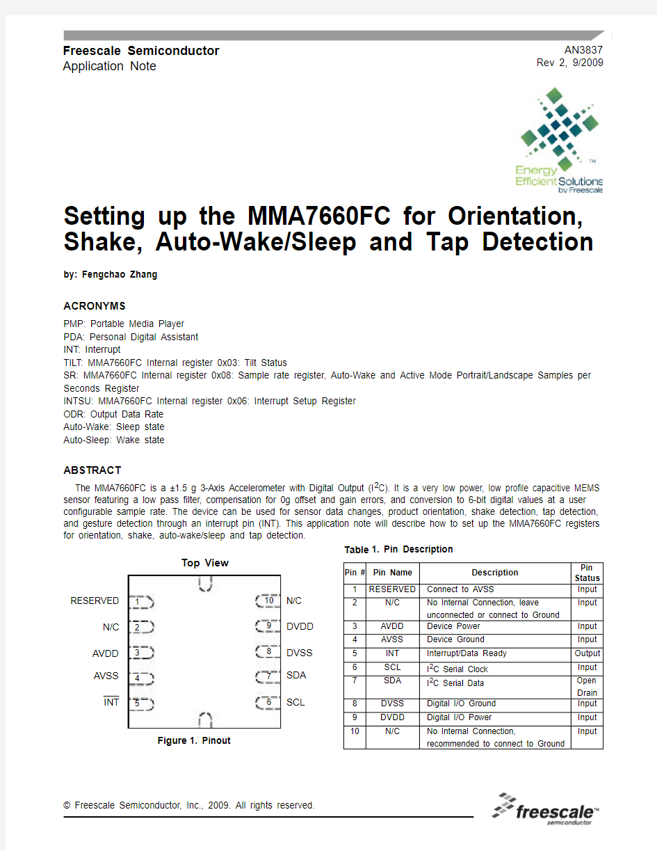
Figure 1. Pinout
Table 1. Pin Description
N/C DVDD DVSS SDA SCL
RESERVED
N/C AVDD AVSS INT
Top View
12345
6
78910Pin #Pin Name Description
Pin Status 1
RESERVED
Connect to AVSS
Input 2N/C No Internal Connection, leave unconnected or connect to Ground Input 3AVDD Device Power Input 4AVSS Device Ground Input 5INT Interrupt/Data Ready Output 6SCL I 2C Serial Clock Input 7SDA I 2C Serial Data Open Drain 8DVSS Digital I/O Ground Input 9DVDD Digital I/O Power
Input 10
N/C
No Internal Connection,
recommended to connect to Ground
Input
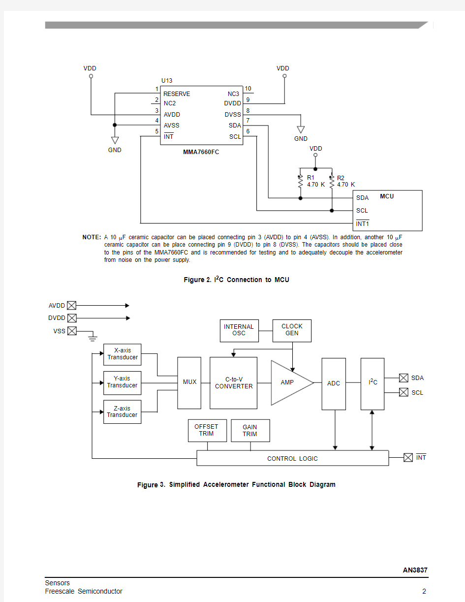
Figure 2. I 2C Connection to MCU
Figure 3. Simplified Accelerometer Functional Block Diagram
NC3DVDD DVSS SDA SCL
RESERVE NC2AVDD AVSS INT
1235
6
789104GND
VDD
VDD
VDD
GND
MMA7660FC
SDA SCL INT1
MCU
R14.70 K R24.70 K
NOTE:A 10 μF ceramic capacitor can be placed connecting pin 3 (AVDD) to pin 4 (AVSS). In addition, another 10 μF
ceramic capacitor can be place connecting pin 9 (DVDD) to pin 8 (DVSS). The capacitors should be placed close to the pins of the MMA7660FC and is recommended for testing and to adequately decouple the accelerometer from noise on the power supply.
U13AVDD DVDD VSS
X-axis Transducer Y-axis Transducer
Z-axis Transducer
MUX
CONTROL LOGIC
INT
C-to-V CONVERTER
AMP
ADC
SDA SCL
OFFSET TRIM
GAIN TRIM
I 2C
INTERNAL OSC
CLOCK GEN
The following are the registers that will be used and/or configured for orientation, shake, auto-wake/sleep and tap detection.
Address Name Function Bit 7Bit 6Bit 5Bit 4Bit 3Bit 2Bit 1Bit 0 0x00XOUT 6 bits output value X-Alert XOUT[5]XOUT[4]XOUT[3]XOUT[2]XOUT[1]XOUT[0] 0x01YOUT 6 bits output value Y-Alert YOUT[5]YOUT[4]YOUT[3]YOUT[2]YOUT[1]YOUT[0] 0x02ZOUT 6 bits output value Z-Alert ZOUT[5]ZOUT[4]ZOUT[3]ZOUT[2]ZOUT[1]ZOUT[0] 0x03TILT Tilt Status Shake Alert Tap PoLa[2]PoLa[1]PoLa[0]BaFro[1]BaFro[0] 0x04SRST Sampling Rate Status000000AWSRS AMSRS 0x05SPCNT Sleep Count SC[7]SC[6]SC[5]SC[4]SC[3]SC[2]SC[1]SC[0] 0x06INTSU Interrupt Setup SHINTX SHINTY SHINTZ GINT ASINT PDINT PLINT FBINT 0x07MODE Mode IAH IPP SCPS ASE AWE TON-MODE
FILT[2]FILT[1]FILT[0]AWSR [1]AWSR [0]AMSR [2]AMSR [1]AMSR [0] 0x08SR Auto-Sleep and Active
Mode Portrait/Landscape
Sample Rates and
Debounce Filter
0x09PDET Tap Detection ZDA YDA XDA PDTH[4]PDTH[3]PDTH[2]PDTH[1]PDTH[0] 0x0A PD Tap Debounce Count PD[7]PD[6]PD[5]PD[4]PD[3]PD[2]PD[1]PD[0] Factory Reserved --------
0x0B to
0x1F
Signed byte 6 bit 2’s complement data with allowable range of +31 to -32
XOUT[5] is 0 if the g direction is positive, 1 if the g direction is negative.If the Alert bit is set, the register was read at the same time as the device was attempting to update the contents. The register must be read again.
Signed byte 6 bit 2’s complement data with allowable range of +31 to -32.
YOUT[5] is 0 if the g direction is positive, 1 if the g direction is negative.If the Alert bit is set, the register was read at the same time as the device was attempting to update the contents. The register must be read again.
Signed byte 6 bit 2’s complement data with allowable range of +31 to -32.
ZOUT[5] is 0 if the g direction is positive, 1 if the g direction is negative.If the Alert bit is set, the register was read at the same time as the device was attempting to update the contents. The register must be read again.
BaFro[1:0]
00:Unknown condition of front or back
01:Front:Equipment is lying on its front
10:Back:Equipment is lying on its back
PoLa[2:0]
000:Unknown condition of up or down or left or right
001:Left:Equipment standing vertically in normal orientation (any markings are the right way up)
010:Right:Equipment standing vertically in inverted orientation (any markings are the wrong way up)
101:Down:Equipment is in landscape mode to the right 110:Up:Equipment is in landscape mode to the left Tap
0:Equipment has detected a tap
1:Equipment has not detected a tap
Alert
0:Register data is valid
1:The register was read at the same time as MMA7660FC was attempting to update the contents. Re-read the register Shake
0:Equipment is not experiencing shaking in one or more of the axes enabled by SHINTX, SHINTY, and SHINTZ
1:Equipment is experiencing shake in one or more of the axes enabled by SHINTX, SHINTY, and SHINTZ
0x00: XOUT: 6 bits Output Value X
D7D6D5D4D3D2D1D0—Alert XOUT[5]XOUT[4]XOUT[3]XOUT[2]XOUT[1]XOUT[0] 00000000
0x01: YOUT: 6 bits Output Value Y
D7D6D5D4D3D2D1D0—Alert YOUT[5]YOUT[4]YOUT[3]YOUT[2]YOUT[1]YOUT[0] 00000000
0x02: ZOUT: 6 bits Output Value Z
D7D6D5D4D3D2D1D0—Alert ZOUT[5]ZOUT[4]ZOUT[3]ZOUT[2]ZOUT[1]ZOUT[0] 00000000
0x03: TILT: Tilt Status (Read only)
D7D6D5D4D3D2D1D0 Shake Alert Tap PoLa[2]PoLa[1]PoLa[0]BaFro[1]BaFro[0] 00000000
AMSRS
0:Sample rate specified in AMSR[2:0] is not active 1:Sample rate specified in AMSR[2:0] is active AWSRS
0:Sample rate specified in AWSR[1:0] is not active 1:Sample rate specified in AWSR[1:0] is active
Writing Sleep Count register resets the internal sleep counter SC[7:0]
8 bit maximum count value for the 8 bit internal sleep counter in Auto-Sleep. When the 8 bit internal sleep counter reaches value set by SC[7:0], MMA7660FC will exit Auto-Sleep and switch to the sample rate specified in AWSR[1:0] of the SR register.
FBINT
0:Front/Back position change does not cause an interrupt 1:Front/Back position change (Front bit toggling or Back bit toggling) causes an interrupt
PLINT
0:Up/Down/Right/Left position change does not cause an interrupt
1:Up/Down/Right/Left position change (Up bit toggling or Down bit toggling) causes an interrupt
ASINT
0:Exiting Auto-Sleep does not cause an interrupt
1:Exiting Auto-Sleep causes an interrupt
PDINT
0:Successful tap detection does not cause an interrupt
1:Successful tap detection causes an interrupt
GINT
0:There is not an automatic interrupt after every measurement 1:There is an automatic interrupt after every measurement, when G-cell readings are updated in XOUT, YOUT, ZOUT registers, regardless of whether the readings have changed or not. This interrupt does not affect the Auto-Sleep or Auto-Wake functions.SHINTX
0:Shake on the X axis does not cause an interrupt or set the Shake bit in the TILT register
1:Shake detected on the X axis causes an interrupt, and sets the Shake bit in the TILT register
SHINTY
0:Shake on the Y axis does not cause an interrupt or set the Shake bit in the TILT register
1:Shake detected on the Y axis causes an interrupt, and sets the Shake bit in the TILT register
SHINTZ
0:Shake on the Z axis does not cause an interrupt or set the Shake bit in the TILT register
1:Shake detected on the Z axis causes an interrupt, and sets the Shake bit in the TILT register
The active interrupt condition (IRQ = 0 if IAH = 0, IRQ = 1 if IAH = 1) is released during the acknowledge bit of the slave address transmission of the first subsequent I2C to
MMA7660FC after the interrupt was asserted.
0x04: SRST: Sampling Rate Status (Read Only)
D7D6D5D4D3D2D1D0 000000AWSRS AWSRS 00000000
0x05: SPCNT: Sleep Count Register (Read/Write)
D7D6D5D4D3D2D1D0 SC[7]SC[6]SC[5]SC[4]SC[3]SC[2]SC[1]SC[0] 00000000
0x06: INTSU: Interrupt Setup
D7D6D5D4D3D2D1D0 SHINT X SHINT Y SHINT Z GINT ASINT PDINT PLINT FBINT 00000000
When [TON,MODE] = [0,1], MMA7660FC will only allow write access to the Mode register 0x07.Writing Mode register resets sleep timing, and clears the XOUT, YOUT, ZOUT, TILT registers.Reading Mode register resets sleep timing.
MODE
0: Standby mode or Test Mode depending on state of TON 1: Active mode
Existing state of TON bit must be 0 (MMA7660FC must not be in Test Mode) to write MODE = 1
MMA7660FC always enters Active Mode using the sample rate specified in AMSR[2:0] of the SR register. When MMA7660FC enters Active Mode with
[ASE:AWE]=11, MMA7660FC operates Auto-Sleep functionality first.TON
0:Standby Mode or Active Mode depending on state of MODE 1:Test Mode
Existing state of MODE bit must be 0 (MMA7660FC must be in Standby Mode) to write TON = 1AWE
0:Auto-Wake is disabled 1:Auto-Wake is enabled.
When Auto-Wake functionality is operating, the AWSRS bit is the SRST register is set and MMA7660FC uses the sample rate specified in AWSR[1:0] of the SR register.
When MMA7660FC automatically exits Auto-Wake by a
selected interrupt, MMA7660FC will then switch to the sample rate specified in AMSR[2:0] of the SR register. If ASE = 1, then Auto-Sleep functionality is now enabled.ASE
0:Auto-Sleep is disabled 1:Auto-Sleep is enabled
When Auto-Sleep functionality is operating, the AMSRS bit is the SRST register is set and MMA7660FC uses the sample rate specified in AMSR[2:0] of the SR register.
When MMA7660FC automatically exits Auto-Sleep because the Sleep Counter times out, MMA7660FC will then switch to the sample rate specified in AWSR[1:0] of the SR register. If AWE = 1, the Auto-Wake functionality is now enabled.SCPS
0:Prescaler is divide-by-1. The 8 bit internal Sleep Counter input clock is the sample rate set by AMSR[2:0], so the clock range is 64Hz to 1Hz depending on AMSR[2:0] setting. Sleep Counter time-out range is 256 times the prescaled clock (Table 2.)
1:Prescaler is divide-by-16. The 8 bit Sleep Counter input clock is the sample rate set by AMSR[2:0] divided by 16, so the clock range is 4Hz to 1/16Hz depending on AMSR[2:0] setting. Sleep Counter time-out range is 256 times the prescaled clock (Table 2.).IPP
0:Interrupt output INT is open-drain. Note: do not connect pull-up resistor from INT to higher voltage than DVDD 1:Interrupt output INT is push-pull
IAH
0:Interrupt output INT is active low 1:Interrupt output INT is active high
The active interrupt condition (IRQ = 0 if IAH = 0, IRQ = 1 if IAH = 1) is released during the acknowledge bit of the slave address transmission of the first subsequent I 2C MMA7660FC after the interrupt was asserted.
Table 2. Sleep Counter Timeout Ranges
0x07: MODE: Mode Register (Read/Write)
D7D6D5D4D3D2D1D0IAH IPP SCPS ASE AWE TON —MODE 0
AMSR SCPS = 0
SCPS = 1
Minimum Range (20)
Maximum Range (28)
Minimum Range (20)
Maximum Range (28)
1 SPS 1 s 256 s 16 s 4096 s
2 SPS 0.5 s 128 s 8 s 2048 s 4 SPS 0.25 s 34 s 4 s 1024 s 8 SPS 0.125 s 32 s 2 s 512 s 16 SPS 0.625 s 16 s 1 s 256 s 32 SPS 0.03125 s 8 s 0.5 s 128 s 64 SPS 0.0156 s 4 s 0.25 s 64 s 120 SPS
0.00836 s
2.14 s
0.133 s
34.24 s
0x08: SR:Auto-Wake and Active Mode Portrait/Landscape Sample Rates Register (Read/Write)
D7D6D5D4D3D2D1D0 FILT[2]FILT[1]FILT[0]AWSR[1]AWSR[0]AMSR[2]AMSR[1]AMSR[0] 00000001
AMSR[2:0]NAME DESCRIPTION
000AMPD Tap Detection Mode and 120 Samples/Second Active and Auto-Sleep Mode
Tap Detection Sampling Rate: The device takes readings continually at a rate of nominally 3846 g-cell
measurements a second. It then filters these high speed measurements by maintaining continuous rolling averages
of the current and last g-cell measurements. The averages are updated every 260 μs to track fast moving
accelerations.
Tap detection: Compares the two filtered axis responses (fast and slow) described above for each axis. The absolute
(unsigned) difference between the fast and slow axis responses is compared against the tap detection delta
threshold value PDTH[4:0] in the PDET (0x09) register.
For portrait/landscape detection: The device takes and averages 32 g-cell measurements every 8.36 ms in Active
Mode and Auto-Sleep. The update rate is 120 samples per second. These measurements update the XOUT (0x00),
YOUT (0x01), and ZOUT (0x02) registers also.
001AM6464 Samples/Second Active and Auto-Sleep Mode
For portrait/landscape detection: The device takes and averages 32 g-cell measurements every
15.625 ms in Active Mode and Auto-Sleep. The update rate is 64 samples per second. These measurements update
the XOUT (0x00), YOUT (0x01), and ZOUT (0x02) registers also.
010AM3232 Samples/Second Active and Auto-Sleep Mode
For portrait/landscape detection: The device takes and averages 32 g-cell measurements every 31.25 ms in
Active Mode and Auto-Sleep. The update rate is 32 samples per second. These measurements update XOUT
(0x00), YOUT (0x01), and ZOUT (0x02) registers also.
011AM1616 Samples/Second Active and Auto-Sleep Mode
For portrait/landscape detection: The device takes and averages 32 g-cell measurements every 62.5 ms in Active
Mode and Auto-Sleep. The update rate is 16 samples per second. These measurements update the XOUT (0x00),
YOUT (0x01), and ZOUT (0x02) registers also.
100AM88 Samples/Second Active and Auto-Sleep Mode
For portrait/landscape detection: The device takes and averages 32 g-cell measurements every 125 ms in Active
Mode and Auto-Sleep. The update rate is 8 samples per second. These measurements update the XOUT (0x00),
YOUT (0x01), and ZOUT (0x02) registers also.
101AM4 4 Samples/Second Active and Auto-Sleep Mode
For portrait/landscape detection: The device takes and averages 32 g-cell measurements every 250 ms in Active
Mode and Auto-Sleep. The update rate is 4 samples per second. These measurements update the XOUT (0x00),
YOUT (0x01), and ZOUT (0x02) registers also.
110AM2 2 Samples/Second Active and Auto-Sleep Mode
For portrait/landscape detection: The device takes and averages 32 g-cell measurements every 500 ms in Active
Mode and Auto-Sleep. The update rate is 2 samples per second. These measurements update the XOUT (0x00),
YOUT (0x01), and ZOUT (0x02) registers also.
111AM1 1 Sample/Second Active and Auto-Sleep Mode
For portrait/landscape detection: The device takes and averages 32 g-cell measurements every 1000 ms in Active
Mode and Auto-Sleep. The update rate is 1 sample per second. These measurements update the XOUT (0x00),
YOUT (0x01), and ZOUT (0x02) registers also.
AWSR[1:0]NAME DESCRIPTION
00AW3232 Samples/Second Auto-Wake Mode
For portrait/landscape detection: The device takes and averages 32 g-cell measurements every
31.25 ms in Auto-Wake. The update rate is 32 samples per second. These measurements update the
XOUT (0x00), YOUT (0x01), and ZOUT (0x02) registers also.
01AW1616 Samples/Second Auto-Wake Mode
For portrait/landscape detection: The device takes and averages 32 g-cell measurements every
62.5 ms in Auto-Wake. The update rate is 16 samples per second. These measurements update the
XOUT (0x00), YOUT (0x01), and ZOUT (0x02) registers also.
10AW88 Samples/Second Auto-Wake Mode
For portrait/landscape detection: The device takes and averages 32 g-cell measurements every 125
ms in Auto-Wake. The update rate is 8 samples per second. These measurements update the XOUT
(0x00), YOUT (0x01), and ZOUT (0x02) registers also.
11AW1 1 Sample/Second Auto-Wake Mode
For portrait/landscape detection: The device takes and averages 32 g-cell measurements every
1000 ms in Auto-Wake. The update rate is 1 sample per second. These measurements update the
XOUT (0x00), YOUT (0x01), and ZOUT (0x02) registers also.
FILT[2:0]DESCRIPTION
000Tilt debounce filtering is disabled. The device updates portrait/landscape every reading at the rate set by AMSR[2:0] or AWSR[1:0]
0012 measurement samples at the rate set by AMSR[2:0] or AWSR[1:0] have to match before the device updates portrait/landscape data in TILT (0x03) register.
010 3 measurement samples at the rate set by AMSR[2:0] or AWSR[1:0] have to match before the device updates portrait/landscape data in TILT (0x03) register.
011 4 measurement samples at the rate set by AMSR[2:0] or AWSR[1:0] have to match before the device updates portrait/landscape data in TILT (0x03) register.
100 5 measurement samples at the rate set by AMSR[2:0] or AWSR[1:0] have to match before the device updates portrait/landscape data in TILT (0x03) register.
101 6 measurement samples at the rate set by AMSR[2:0] or AWSR[1:0] have to match before the device updates portrait/landscape data in TILT (0x03) register.
1107 measurement samples at the rate set by AMSR[2:0] or AWSR[1:0] have to match before the device updates portrait/landscape data in TILT (0x03) register.
1118 measurement samples at the rate set by AMSR[2:0] or AWSR[1:0] have to match before the device updates portrait/landscape data in TILT (0x03) register.
XDA
1:X-axis is disabled for tap detection 0:X-axis is enabled for tap detection YDA
1: Y-axis is disabled for tap detection 0: Y-axis is enabled for tap detection
ZDA
1: Z-axis is disabled for tap detection 0: Z-axis is enabled for tap detection
$0A: Tap/Pulse Debounce Count Register (Read/Write)PD
$09: PDET: Tap/Pulse Detection Register (Read/Write)
D7D6D5D4D3D2D1D0ZDA YDA XDA PDTH[4]
PDTH[3]
PDTH[2]
PDTH[1]
PDTH[0]
PDTH[4:0]DESCRIPTION
00000Tap detection threshold is ±1 count 0000100010Tap detection threshold is ±2 counts 00011Tap detection threshold is ±3 counts ...... and so on up to...
11101Tap detection threshold is ±29 counts 11110Tap detection threshold is ±30 counts 11111
Tap detection threshold is ±31 counts
D7D6D5D4D3D2D1D0PD[7]PD[6]PD[5]PD[4]PD[3]PD[2]PD[1]PD[0]0
PD[4:0]DESCRIPTION
00000000The tap detection debounce filtering requires 2 adjacent tap detection tests to be the same to trigger a tap event and set the Tap bit in the TILT (0x03) register, and optionally set an interrupt if PDINT is set in the INTSU (0x06) register. Tap detection response time is nominally 0.52 ms
0000000100000010
Tap detection debounce filtering requires 3 adjacent tap detection tests to be the same to trigger a tap event and set the Tap bit in the TILT (0x03) register, and optionally set an interrupt if PDINT is set in the INTSU (0x06) register. Tap detection response time is nominally 0.78 ms
00000011
Tap detection debounce filtering requires 4 adjacent tap detection tests to be the same to trigger a tap event and set the Tap bit in the TILT (0x03) register, and optionally set an interrupt if PDINT is set in the INTSU (0x06) register. Tap detection response time is nominally 1.04 ms ...... and so on up to...
11111101
Tap detection debounce filtering requires 254 adjacent tap detection tests to be the same to trigger a tap event and set the Tap bit in the TILT (0x03) register, and optionally set an interrupt if PDINT is set in the INTSU (0x06) register. Tap detection response time is nominally 66.04 ms
11111110
Tap detection debounce filtering requires 255 adjacent tap detection tests to be the same to trigger a tap event and set the Tap bit in the TILT (0x03) register, and optionally set an interrupt if PDINT is set in the INTSU (0x06) register. Tap detection response time is nominally 66.3 ms
11111111
Tap detection debounce filtering requires 256 adjacent tap detection tests to be the same to trigger a tap event and set the Tap bit in the TILT (0x03) register, and optionally set an interrupt if PDINT is set in the INTSU (0x06) register. Tap detection response time is nominally 66.56 ms
Table3. Orientation Detection Logic of when Interrupt will Occur
Orientation Xg Yg Zg Shake|X|> +1.3g or|Y|> +1.3g or|Z|> +1.3g Up|Z| < 0.8g and |X| > |Y| and X < 0
Down|Z| < 0.8g and |X| > |Y| and X > 0
Right|Z| < 0.8g and|Y| > |X| and Y < 0
Left|Z| < 0.8g and |Y| > |X| and Y > 0
Back Z < -0.25g Front Z > 0.25g
Figure 4. Flow Chart of Orientation Detection
SAMPLE RATE
The sampling rate can be selected based on the targeted power consumption per the application specification or the desired response rate of the orientation detection. The following are the sample rates available in the MMA7660FC sensor with the corresponding approximate power consumption rates.
NOTE: These power consumption rates were tested in the factory and could vary depending on the PCB board design.
Table4. Sample Rate vs. Current Consumption
Sampling Rate Current Consumption
Stand By 2.33 μA
1 SPS46.9 μA
2 SPS49.
3 μA
4 SPS54 μA
8 SPS65.8 μA
16 SPS89.2 μA
64 SPS221 μA
32 SPS133 μA
120 SPS294 μA
ORIENTATION DETECTION
The MMA7660FC has the built in capability to do orientation detection. This feature gives the customer the capability to do applications such as portrait/landscape in mobile phones/PMP/PDAs. The tilt orientation of the device is in 3 dimensions and is identified in its last known static position. This allows a product to set its display orientation appropriately to either portrait or landscape mode or to turn off the display when the device is placed upside down. The sensor provides 6 different positions: left, right, up, down, back, and front. This application note will explain how to configure the MMA7660FC to do orientation detection given the desired sample rate or targeted power consumption.
Setting up the INSU[0x06] Register for Orientation Detection Only
Based on the application specification of the MMA7660FC sensor can be configured to report back/front interrupts and/or up/down/left/right interrupts. If the application targets to use back and front the FBINT bit must be set to 1. If the back and front interrupt is not desired than set the FBINT bit to 0. If the application targets Up/Down/Left/Right interrupts then the PLINT bit must be set to 1. If the Up/Down/Left/Right interrupt is not desired then set the PLINT bit should be set to 0.
$06: Interrupt Setup Register
INTSU
D7D6D5D4D3D2D1D0
X X X X X X PLINT FBLINT 00000000
Setting up the SR (0x08) Register for Orientation Detection Only
The sample rate must be selected based on target power consumption level and/or desired response rate for the orientation detection application. To set up the sample rate the AMSR[3:0] must be configured. Given the selected sample rate a debounce filter setting (FILT[3:0]) must be set also. Application testing has been done to correlate the sample rate and the recommended debounce filter setting.Refer to “Sample Rate vs. Debounce Filter Table”.
$08: Auto-Wake and Active Mode Portrait/Landscape Output Data Rates Register (Read/Write)
SR - Sample Rate Register
D7D6D5D4D3D2D1D0 FILT[2]FILT[1]FILT[0]X X AMSR[2]AMSR[1]AMSR[0] 00000000
Table5. Sample Rate vs. Debounce Filter Table
Sample Rate Debounce Filter Setting
1 SPS4
2 SPS6
4 SPS8
8 SPS8
16 SPS8
32 SPS8
64 SPS External Debounce Filter
120 SPS External Debounce Filter
NOTE:The recommended values were tested on the RD3803MMA7660FC.The values may change given the mounting and position of the sensor on the PCB design.
HANDLING THE ORIENATION DETECTION INTERRUPT
When an interrupt occurs the application must read the TILT (0x03) register. When reading the TILT register the bits of interest are the following POLA[4:2] and BAFRO[1:0]. The interrupt will be cleared when the TILT register is read.
$03: Tilt Status (Read Only)
TILT
D7D6D5D4D3D2D1D0
X ALERT X PoLa[2]PoLa[1]PoLa[0]BaFro[1]BaFro[0] 00000000 NOTE:For further description of the INTSU (0x06), SR (0x08) and TILT (0x03) register, please refer to the MMA7660FC Data Sheet.
External Debounce Filter
When using the MMA7660FC and sample rates higher than 32 SPS an external debounce filter must be added to avoid flickering between positions due to involuntary human movement. The external debounce filter must be added to the application microcontroller. Below is a flow chart AND Pseudocode for the debounce filter.
Figure 5. External Debounce Filter
REFERENCE CODE:
//Configure MMA7660FC as Portrait/Landscape Detection
Write to the MODE register = 0x00//Standby Mode
Write to the SPCNT register = 0x00//No sleep count
Write to the INTSU register = 0x03//Configure GINT Interrupt
Write to the PDET register = 0xE0//No tap detection enabled
Write to the SR register = 0x34//8 samples/s, TILT debounce filter = 2
Write to the PD register = 0x00//No tap detection debounce count enabled
Write to the MODE register = 0x41//Active Mode, INT = push-pull and active low
//Interrupt service routine
If (Orientation INT occurs)
REGTILT=Read TILT Register;//Read TILT Register value
Switch (Pola [2:0])//Judge the sensor position
Case 1: Orientation=Left;
Case 2: Orientation=Right;
Case 5: Orientation=Down;
Case 6: Orientation=UP;
Switch (BaFro [1:0])//Judge the sensor position
Case 1: Orientation=Front;
Case 2: Orientation=Back;
SHAKE DETECTION
The shake feature can be used as a button replacement to perform functions such as scrolling through images or web pages on a Mobile Phone/PMP/PDA. The customer can enable the shake interrupt on any of the 3 axes, by enabling the SHINTX, SHINTY, and/or SHINTZ in the INTSU (0x06) register.
MMA7660FC detects shake by examining the current 6-bit measurement for each axis in XOUT, YOUT, and ZOUT. The axes that are tested for shake detection are the ones enabled by SHINTX, SHINTY, and/or SHINTZ. If a selected axis measures greater than 1.3g or less than -1.3g, then a shake is detected for that axis and an interrupt occurs. All three axes are checked independently, but a common Shake bit in the TILT register is set when shake is detected in any one of the selected axes. Therefore when all 3 axes (SHINTX, SHINTY, and/or SHINTZ) are selected the sensor will not know what axis the shake occurred. When the TILT register is read the Shake bit is cleared during the acknowledge bit of the read access to that register and shake detection monitoring starts again.
Setting up the INSU[0x06] Register for Shake Detection
Based on the application specification of the MMA7660FC sensor can be configured to report shake interrupts. It can be configured as individual axis or combined axes shake detection. If SHINTX/SHINTY/SHINTZ is set to 1, X/Y/Z axis is enabled for shake detection; and if SHINTX/SHINTY/SHINTZ is set to 0, X/Y/Z axis is not desired for shake detection.
$06: Interrupt Setup Register Tilt Status
INTSU
D7D6D5D4D3D2D1D0 SHINTX SHINTY SHINTZ X X X X X 00000000
Setting up the SR(0x08) Register for Shake Detection
The sample rate must be selected based on target power consumption level and/or desired response rate for the shake detection application.To set up the sample rate the AMSR[3:0]bits in the SR register must be configured.
$08: Auto-Wake and Active Mode Portrait/Landscape Output Data Rates Register (Read/Write)
SR - Sample Rate Register
D7D6D5D4D3D2D1D0
X X X X X AMSR[2]AMSR[1]AMSR[0] 00000000
HANDLING THE SHAKE DETECTION INTERRUPT
When an interrupt occurs, the application must read the TILT (0x03) register. When reading the TILT register, the bit of interest is the shake. If the alert bit is high, the data is invalid.NOTE: For further description of the INTSU (0x06), SR (0x08) and TILT (0x03) register, please refer to the MMA7660FC Data Sheet.
PLEASE NOTE: All three axes are checked independently, but a common Shake bit in the TILT register is set when shake is detected in any one of the selected axes. Therefore when all 3 (SHINTX, SHINTY, and/or SHINTZ) are selected the sensor will not know what axis the shake occurred.
Figure 6 shows the flowchart of shake detection.
Figure 6. Flow Chart of Shake Detection Algorithm
$03: Tilt Status (Read Only)TILT
D7D6D5D4D3D2D1D0Shake Alert X X X X X X 0
Start
Set the ODR in AMSR[2:0]MMA7660FC examines the enabled If one of the values >1.3g or < -1.3g
Update TILT (0x03) register,
Interrupt occur. When the TILT (0x03)No
Configure the Shake interrupt on any of the 3 axes, by enabling the
axis (axes) values in XOUT, YOUT
(AWSR[1:0] in Auto-wake mode)
Yes
Yes
No
SHINTX, SHINTY, and/or
SHINTZ in INTSU
and/or ZOUT
register is read, Shake Detection
start again
REFERENCE CODE
//Configure MMA7660FC as Shake Detection
Write to the MODE register = 0x00//Standby Mode
Write to the SPCNT register = 0x00//No sleep count
Write to the INTSU register = 0xE0//Configure Shake Interrupt on 3 axes
Write to the PDET register = 0xE0//No tap detection enabled
Write to the SR register = 0x02//32 samples/s
Write to the PD register = 0x00//No tap detection debounce count enabled
Write to the MODE register = 0x41//Active Mode, INT = push-pull and active low //Interrupt service routine
If (Shake INT occurs)
REGTILT=Read TILT Register;//Read TILT Register value
If (Shake =1)//Verify “Shake” bit in TILT register
Shake occurs
TAP DETECTION
The MMA7660FC also includes a Tap Detection feature that can be used for a number of different customer applications such as button replacement. For example, a single tap can stop a song from playing and a double tap can play a song. This function detects a fast transition that exceeds a user-defined threshold (PDET (0x09) register) for a certain duration of time (PD (0x0A) register).
Tap Detection Setup
In order to enable Tap detection in the device the user must enable the Tap Interrupt in the INTSU (0x06) register and set the AMSR[2:0] = 000 in the SR (0x08) register. In this mode, TILT (0x03) register, XOUT (0x00), YOUT (0x01), and ZOUT (0x02) registers will update at the 120 samples/second.
NOTE: Delta G is available with any AMSR setting, when XDA = YDA = ZDA = 1 (PDET = 1). When the sampling rate is less than 120 samples/second, the device cannot detect tapping, but can detect small tilt angles (30 degree angle change) which can not be detected by orientation detection.
Setting up the INSU [0x06] Register for Tap Detection
The MMA7660FC sensor can be configured to report tap interrupt by configuring PDINT bit to 1; if the bit is set to 0, tap detection is disabled.
$06: Interrupt Setup Register
INTSU
D7D6D5D4D3D2D1D0
X X X X PDINT X X X
00000000 Setting up the SR (0x08) Register for Tap Detection
The sample rate must be set at 120 samples/second, AMSR [3:0] must be 000.
$08: Auto-Wake and Active Mode Portrait/Landscape Output Data Rates Register (Read/Write)
SR - Sample Rate Register
D7D6D5D4D3D2D1D0
X X X X X AMSR[2]AMSR[1]AMSR[0] 00000000
Setting up PDET (0x09) Register for Tap Detection
The user can configure Tap Detection to be detected on X and/or Y and/or Z axes. The Customer can configure this by changing the XDA, YDA, and/or ZDA bit in the PDET (0x09) register. The bits PDTH [4:0] is used to set the tap threshold form ±1 count to ±31 counts.
0x09: Tap Detection Register (Read/Write)
PDET
D7D6D5D4D3D2D1D0 ZDA YDA XDA PDTH[4]PDTH[3]PDTH[2]PDTH[1]PDTH[0] 00000000
Setting up PD (0x0A) Register for Tap Detection:
The user can configure Tap Debounce Count by PD [7:0] in the PD register to avoid some error trigger, Tap detection debounce filtering requires 2 to 256 adjacent tap detection tests (0.52ms to 66.56ms) to be the same to trigger a tap event and set the Tap bit in the TILT (0x03) register to high, and optionally set an interrupt if PDINT is set in the INTSU (0x06) register.
0x0A: Tap Debounce Count Register (Read/Write)
PD
D7D6D5D4D3D2D1D0 PD[7]PD[6]PD[5]X X X X X
00000000
HANDLING THE TAP DETECTION INTERRUPT
Detection for enabled axes is decided on an OR basis: If the PDINT bit is set in the INTSU (0x06) register, the device reports the first axis for which it detects a tap by the Tap bit in the TILT (0x03) register. When the Tap bit in the TILT (0x03) register is set, tap detection ceases, but the device will continue to process orientation detection data. Tap detection will resume when the TILT (0x03) register is read.
$03: Tilt Status (Read only)
TILT
D7D6D5D4D3D2D1D0
X Alert TAP X X X X X
00000000 NOTE:For further description of the INTSU (0x06), SR (0x08), PDET (0x09), PD (0x0A) and TILT (0x03) register, please refer to the MMA7660FC Data Sheet.
Figure 7. Flow Chart of Tap Detection Algorithm
REFERENCE CODE
//Configure MMA7660FC as Tap Detection Write to the MODE register = 0x00 //Standby Mode Write to the SPCNT register = 0x00//No sleep count
Write to the INTSU register = 0x04// Configure tap detection Interrupt
Write to the PDET register = 0x6C // Only Z axis tap detection on, threshold ±12//counts
Write to the SR register = 0x00//120 samples/s
Write to the PD register = 0x08// Tap detection debounce count = 9
Write to the MODE register = 0x41
//Active Mode, INT = push-pull and active low
//Interrupt service routine
If (Tap INT occurs)
REGTILT=Read TILT Register ; //Read TILT Register value
If (Tap =1)//Verify ”Tap” bit in TILT register
Tap occurs
Start
Set the PDINT in INTSU register
Update TILT (0x03) register,Interrupt occur. Tap detection will No
Configure the active axis (axes)and set the Tap Threshold in PDET,and AWSR[2:0] = 000
Yes
select the Tap Debounce Count
in PD register
resume when the TILT (0x03)
Tap Threshold?
Tap Occur that meets No
Tap Threshold?
Tap Occur that meets Yes
register is read
AUTO-WAKE/SLEEP
The MMA7660FC has the Auto-Wake/Sleep feature that can be enabled for power saving. In the Auto-Wake (sleep state) function, the device is put into a user specified low sample rate (1 sample/second, 8 samples/second, 16 samples/second, or 32 samples/second) in order to minimize power consumption. When the Auto-Wake is enabled and activity is detected such as a change in orientation, pulse event, Delta G acceleration or a shake event, then the device wakes up (Table 4). Auto-Wake will automatically enable Auto-Sleep when the device is in wake mode and can therefore be configured to cause an interrupt on wake-up, by configuring the part to either wake up with a change in orientation, shake, or if using the part at 120 samples/second tap detection.
When the device is in Auto-Wake mode, the MODE (0x07) register, bit AWE is high. When the device has detected a change in orientation, a tap, a shake, or Delta G (change in acceleration) the device will enter Auto-Sleep mode. In the Auto-Sleep (wake state) function, the device is put into any of the following user specified sample rate (1 sample/second, 2 samples/second, 4 samples/second, 8 samples/second, 16 samples/second, 32 samples/second, 64 samples/second, and 120 samples/second). In the Auto-Sleep mode, if there is no change in the orientation, shake or tap has been detected and the sleep counter has elapsed, the device will go into the Auto-Wake mode. When the device is in the Auto-Sleep mode, the MODE (0x07) register, bit ASE is high. The device can be programmed to continually cycle between Auto-Wake/Sleep.
Setting up the MODE[0x07] Register for Auto-Sleep and Auto-Wake
Based on the application specification of the MMA7660FC sensor can be configured to auto-sleep and auto-wake. When Auto-Wake functionality is desired AWE must be set to 1. When the device enters Auto-Wake mode, the AWSRS bit in the SRST register is set and the device uses the samples per second specified in AWSR[1:0] of the SR (0x08) register. When the device exits Auto-Wake mode by any of the selected interrupts, the device will then enter Auto-Sleep Mode (the ASE bit must be set to 1). The device will switch to the samples per second specified in AMSR[2:0] of the SR (0x08) register.
When Auto-Sleep functionality is operating, the AMSRS bit in the SRST register is set and the device uses the sample rate specified in AMSR[2:0] of the SR (0x08) register. When MMA7660FC automatically exits Auto-Sleep mode because the Sleep Counter times out, the device will then switch to the samples per second specified in AWSR[1:0] of the SR register. If AWE = 1, then Auto-Wake functionality is enabled.
If SCPS bit is set to 1 the sleep counter input clock is the sample rate set by AMSR divided by 16. When selected the sleep counter time-out ranges from 64s to 4096s (68 minutes).
If SCPS bit is set to 0, the prescaler is divide-by-1. The 8-bit internal Sleep Counter input clock is the samples per second set by AMSR[2:0], so the sleep Counter time-out range is 2.13s to 256s (4.25 minutes).
Setting up the SRST Register
When an interrupt occurs, read the SRST register. If AMSRS bit is high, the Auto-Sleep in enabled. If AWSRS is high the Auto-Wake is enabled.
Table 6. Auto-Wake/Sleep Truth Table
Trigger Wake-up Reset
Sleep Counter Trigger
Sleep Mode
Orientation Detection Change Yes Yes No Shake
Yes
Yes No Delta G
(set with PD (0x0A) and PDET (0x09))Yes
(XDA = YDA = ZDA = 0)
Yes No Pulse Detect (120 samples/second)Yes Yes No Sleep Counter Elapse
No
No
Yes
$04: Sample Rate Status Register (Read only)SRST
D7D6D5D4D3D2D1D0000000AWSRS
AWSRS
实验2 总账系统初始化设置实验 一、实验目的与要求 1、熟悉总账系统初始化设置的主要流程和内部控制; 2、掌握选项设置方法。 3、掌握录入普通科目及辅助核算项目期初余额的方法; 4、熟悉期初余额对账、试算平衡方法; 二、实验重点、难点:设置总账的选项、录入期初余额、试算平衡并对账 三、实验准备 1、配置应用服务器 2、设置系统日期为“2016年1月1日” 3、启动系统管理,引入实验1结果帐套。 4、启动U8企业应用平台。 四、实验内容 1、设置总账的选项 (1)可以使用应收受控科目 (2)可以使用应付受控科目; (3)不允许修改作废他人填制的凭证; (4)出纳凭证必须经过出纳签字; (5)数量、单价小数位2位,其他选项保持系统默认设置。
注:黄色底纹的为非末级科目,蓝色底纹的为有辅助核算的会计科目。 项目核算期初资料。 供应商往来期初资料 3、试算平衡并对账 4、帐套输出 输出001账套,保存到自己名下的文件夹下。 五、详细操作指导 (—)实验准备操作过程(若连续实验,可略过步骤1-4) 1、应用服务器配置:将数据库服务器名设置为你的计算机名称。(具体设置参见实验1) 2、设置系统日期(具体设置参见实验1) 3、启动系统管理,引入实验1结果帐套。 以系统管理员Admin身份注册系统管理,单击“帐套”菜单下的“引入”,选择帐套所在的路径,引入实验1的结果账套,单击“确定”后,系统将恢复账套(001)四方科技有限公司。
4、启动U8企业应用平台。 单击开始图标—所有程序—用友U8V10.1—U8企业应用平台;或者直接双击桌面上的。打开 U8企业应用平台登录窗口。 以账套主管2011张芳1身份登录。注意输入正确的数据库服务器名为你的计算机名称。选择账套001。操作日期2016-01-01(注意:有些电脑时间是自动修正,所以登录时一定要更改时间)。 (二)实验内容操作过程 1、设置总账的选项,主要是凭证选项,具体如下: 从业务导航视图选择业务工作—财务会计—总账—设置—选项,双击后打开选项窗口。 如果系统出现下面提示信息时,需要对系统时间进行重新设置。具体设置方法如下:
扫描枪操作手册 一、入库扫描与文件上传 1、打开扫描枪,从“入库扫描——不区分仓库”进入扫描界面扫描待入库物品。 2、扫描完成后,打开电脑桌面上传程序进入等待界面,然后进入扫描枪界面——“数 据通讯”,点击数字键7启动通讯按钮,开始文件上传。 3、入库扫描上传完毕。 4、ERP中入库操作完成后,备份入库条码文件至入库文件夹,删除扫描枪内条码文件。 二、出库扫描、订单下载与文件上传 1、打开扫描枪,进入系统设置——数据通讯,选择端口com(u),点OK进入订单下载待机界面。 2、打开ERP进入“订单查询”界面,选择需要扫描发货的订单,右键选择“导出自动配单”,在弹出界面中选择盘符C:\,确定后提示已有订单文件存在,是否追加。如选择是,则在原有的订单文件中加入新的订单,如选择否,则用现有订单文件覆盖原有订单文件。 3、订单下载完成后,打开扫描枪,从“出库扫描——自动配单”进入条码扫描界面扫描待出库物品。 4、扫描完成后,打开电脑桌面上传程序进入等待界面,然后进入扫描枪界面——“数据通讯”,点击数字键7启动通讯按钮,开始文件上传。 5、出库扫描上传完毕。 6、ERP中出库操作完成后,备份出库条码文件至出库文件夹,删除扫描枪内条码文件。 三、盘点扫描与文件上传 1、打开扫描枪,从“盘点扫描”进入扫描界面扫描待盘点物品。 2、扫描完成后,打开电脑桌面上传程序进入等待界面,然后进入扫描枪界面——“数据通讯”,点击数字键7启动通讯按钮,开始文件上传。 3、盘点扫描上传完毕。 4、ERP中盘点操作完成后,备份出库条码文件至入库文件夹,删除扫描枪内条码文件。
四、扫描枪数据删除 1、当入库扫描和出库扫描文件上传完毕,并且入库与发货都已做好之后,可以把扫描枪里面不再需要的入库文件和出库文件删除。 2、打开扫描枪,进入“数据删除”,此时会有三个选项,其中“逐条删除”表示一个一个条形码删除,这个删除功能只能删除条码,不能删除条码文件;“扫描删除”功能和“逐条删除”一样,只是删除的方式不同,“扫描删除”是利用扫描枪,每扫描到一个条码,就把扫描枪里原有的对应条码删除;“全部删除”表示整个删除条码文件。 3、上述三个删除方法中,删除按钮均有两个,一个“功能”键表示全删,一个“回删”键表示单删。
扫描枪常见的故障及处 理方法 标准化管理处编码[BBX968T-XBB8968-NNJ668-MM9N]
扫描枪常见的故障及处理方法 成都厂扫描枪分类: 1)一维扫描枪:(条形码扫描枪) 2)二维扫描枪:(CPU扫描枪) 一维扫描枪工作原理: 激光扫描仪的基本工作原理为:手持式激光扫描仪通过一个激光二极管发出一束光线,照射到一个旋转的棱镜或来回摆动的镜子上,反射后的光线穿过阅读窗照射到条码表面,光线经过条或空的反射后返回阅读器,由一个镜子进行采集、聚焦,通过光电转换器转换成电信号,该信号将通过扫描器或终端上的译码软件进行译码。 如果条码无法正确的识别到,光源线会一直亮着,这其实是扫描枪一直在解码的过程,如果解码成功,光线就自动灭掉。 常见故障: 1)扫描枪亮红灯,无法读取数据或者数据读取不完整。 故障表现:扫描枪线材损坏,参数设置不正确, 2)扫描枪无激光。 故障表现:扫描枪内部电路板损坏或者是没有更新扫描枪驱动(参见:进入管理员账号,更新设备驱动) 设置方法: 1)基本设置手册 2)自动发送F1设置手册 接口种类:USB接口,PS/2接口,RS232接口
二维码扫描枪工作原理: 二维码(dimensional barcode),又称二维条码,是在一维条码的基础上扩展出的一种具有可读性的条码。设备扫描二维条码,通过识别条码的长度和宽度中所记载的二进制数据,可获取其中所包含的信息。相比一维条码,二维码记载更复杂的数据,比如图片、网络链接、视频等。 简介 二维条码/二维码(dimensional barcode)是用某种特定的几何图形按一定规律在平面(二维方向上)分布的黑白相间的图形记录数据符号信息的;在代码编制上巧妙地利用构成计算机内部逻辑基础二维码的“0”、“1”比特流的概念,使用若干个与二进制相对应的几何形体来表示文字数值信息,通过图象输入设备或光电扫描设备自动识读以实现信息自动处理:它具有条码技术的一些共性:每种码制有其特定的字符集;每个字符占有一定的宽度;具有一定的校验功能等。同时还具有对不同行的信息自动识别功能、及处理图形旋转变化等特点。 常见故障: 1)能读码,电脑上无数据传输。 故障表现:线材损坏,接口松脱,没有正确设置仿真USB接口。 2)能读码,读码能力弱。 故障表现:扫描枪设置不正确,扫描枪内部部件老化损坏。 设置方法: 1)参照二维扫描枪设置手册
复习上节内容: 1、系统启用的两种方法是什么? 答:一种是在企业建账完成后立即进行系统启用;另一种是在建账结束后由账套主管在企业门户中进行系统启用。 2、系统管理员能否进入企业门户?为什么? 答:系统管理员不能进入企业门户,因为他不能进行业务处理。 前两次上机出现的问题 一、服务器:一台电脑一个服务器。例如:10,kd11。
注意:第一次进入某个系统,如“企业门户”,需输入服务器名;以后再进,直接进入。 二、账套引入 电脑被写保护,往后每次上机先做账套引入,下机前别忘了做账套输出。 具体操作:从优盘中把某个文件夹,如20100910张三,复制、粘贴到D盘下,同时关闭优盘的窗口。系统管理员(admin)注册系统管理,做账套引入。系统提示“是否改变路径”,单击[否]。如果再出现一个提示“是否覆盖某账套”,
单击[是]。引完后,在D盘下重新建一个新文件夹,如20100916张三。 三、账套备份(账套输出) 具体操作:下机前,系统管理员(admin)做账套输出,选中自己的账套,[确认]。选备份路径时,双击D盘下文件夹,如20100316张三,[确认]。把D盘下文件夹发送到优盘中。引入新课: 2.账套初始化 2.2总账系统的初始化设置 一、任务 1、设置系统参数
示例2.3:300账套总账系统的参数:不允许修改、作废他人填制的凭证;凭证审核控制到操作员;进行支票控制;出纳凭证必须由出纳签字;凭证必须由会计主管签字。 设置∣选项,选好参数后,[编辑],[确定]。 注意:制单序时控制:先做1日的凭证,再做2日的凭证,…… □制单序时控制:可先做10日的凭证,再做1日的凭证。 2、设置外币 示例2.4:外币币种为美元,
第一篇总账系统(F1) 第一章总账系统初始化处理(F1-1) 初始化是指企业账务和物流业务的背景设置和启用账套会计期间的期初数据。本章主要讲述了K/3总账系统在使用前的初始化工作——基础设置和初始数据录入的操作,总账系统的初始化设置是一切K/3系统的开始,所以设置尤为重要. 本章的目的 当完成本章的学习之后,您将能够做以下事情: ●掌握总账系统初始化的流程 ●掌握具体业务数据的操作 ●了解参数设置的含义 ●了解初始化设置的技巧
第一节初始化的流程(F1-1-1) 初始化流程图 K/3财务初始化流程图
案例: 海天有限公司,是一家制造运动服饰的工业企业。该公司的一些基本参数和情况如下: 1.基本情况: 假设公司将于2003年3月使用K/3总账系统。 该公司记账本位币为“人民币”,并有外币“美元”和“港币”。 会计期间采用自然年度会计期间。 税率:采用17%的增值税。 凭证字:“记”。 2.该公司的客户资料: 01华东地区:01.01佳雪服饰公司;01.02飞龙百货公司 02华北地区:02.01雪尼服饰公司; 3.该公司的供应商资料: 01上海:01.01蓝天布料厂;01.02 北新布匹公司 02深圳:02.01柔依衣料公司 4.该公司共有六个部门,分别是: 01总经办;02财务部;03采购部;04销售部;05仓存部;06 生产部;07医务室。 5.公司员工资料:
001张恒(总经办,一般管理员);002李影(财务部,一般管理人员);003王和(采购部,经理);004钱明(销售部,销售人员);005赵苍(仓存部,工人);006刘盛(生产部,生产部管理人员);马浩(医务室,医生)。 6.计量单位: 原料组:001米;成品组:002件。 7.物料资料: 01产成品:01.001运动服,计量单位:件,以加权平均法计价。 01.002游泳衣,计量单位:件,以加权平均法计价。 02原材料:02.001尼龙,计量单位:米,以加权平均法计价。 02.002布料,计量单位:米,以加权平均法计价。 8.仓库汇总: 001原料仓;002成品仓 注意:各管理子系统之间的案例有一定的联系,但并非是一个完整的案例,为教学方便估计有一定出入。财务部分别着重从财务处理的角度应用和理解。
课程实验报告 专业年级10会计学1班 课程名称会计信息系统 指导教师 学生姓名 学号 实验日期2013.3.18 实验地点 实验成绩 教务处制 二〇一三年三月二十八日
实验项目 名称 总账系统初始设置 实验 目的及要求目的: 1、掌握用友财务软件中总账系统初始设置的具体内容与设置方法; 2、理解总账系统初始设置的意义; 3、掌握企业财务应用方案的选择。 要求: 以账套主管“学生姓名1”的身份注册登录总账系统进行初始化设置。 实验内容1、总账系统参数设置; 2、基础档案设置:会计科目、凭证类别、外币及汇率、结算方式、辅助核算档案等; 3、期初余额录入。 实验步骤1、引入账套 (1)执行开始--程序--用友ERP-U8--系统服务--系统管理命令,进入系统管理对话框 (2)单击任务栏上的“ERP-U8系统管理”按钮,进入ERP-U8系统管理窗口。(3)执行系统--注册命令,打开注册系统管理对话框。 (4)系统中预先设定了一个系统管理员admin,第一次运行时,系统默认管理员密码为空,单击确定按钮,以系统管理员身份进入系统管理。 (5)单击账套--引入,再选择需要引入的账套的路径,将上次所做的账套引入到电脑上。 2、注册控制台,启用总账系统 (1)打开"开始"菜单,依次选择"程序"、"用友财务及企管软件",单击其下的"系统控制台"选项; (2)在[注册控制台]对话框,选择刚才引入的账套,选择“学生姓名1”操作员(用户名)单击[确定]按钮,进入用友企业级财务软件主界面; (3)在主界面单击[财务系统]中[总账]选项,由于是第一次启用总账系统,系统出现"总账系统启用"窗口,设置总账系统启用月份;凭证控制选中凭证审核控制到操作员,出纳凭证必须经由出纳签字;凭证编号方式选择系统编号;外币汇率方式选择固定汇率;客户往来款项和供应商往来款项选择总账系统核算。设置完毕,单击[确定]按钮,进入[总账系统]窗口; 3、总账控制参数设置 (1)[总账系统[窗口―[业务工作]―[系统菜单]―[设置]―[选项]; (2)在[选项]窗口,可进行[凭证]、[账簿]、[会计日历]、[其他]选项中的有关设置; ①选择[凭证]标签,在该标签下分别选中 "制单序时控制" "支票控制" "赤字控制:资金及往来科目" "赤字控制方式:提示"、"不可以使用应收、应付、存货控制科目" 取消"现金流量科目必录现金流量项目" "凭证录入时结算方式及票号必录" "凭证系统编号" "不允许修改、作废他人填制的凭证"
收银机的扫描枪常见问题 1、问题描述:激光常亮 可能原因:扫描了说明书设置条码成常亮模式 解决方法:恢复出厂设置退回生产厂商维修 2、问题描述:扫描器扫描,蜂鸣正常,无数据传输。 可能原因:扫描枪设置不正确;线材坏 解决方法:参见说明书,确保使用相应的数据线对应的设置正确。 3、问题描述:接串口线后,读码无数据传输。 可能原因:没有设置成串口模式或通信协议错误。 解决方法:扫描串口模式设置成串口模式,重新设置成正确的通信协议。 4、问题描述:扫描枪读码正常,但无蜂鸣声。 可能原因:设置成了静音 解决方法:扫描一下蜂鸣器“开启”设置。 5、问题描述:扫描器开启正常,出激光,不读码。 可能原因:对应的条码码制关闭或条码被损坏或打印的质量有问题, 硬件故障,主板上电子元器件坏 解决方法:开启对应的条码码制和仔细检查条码是否被损坏和其它同一码制的条码有没有不同。检查打印机的模式。改变一下打印机的设置。 6、问题描述:扫描一个条码后死机或使用USB线材时电脑显示无法识别USB设备。 可能原因:线材不良引起数据无法传递而死机和USB设备不良。 解决方法:找经销商购买更换线材。
7、问题描述:设备连接后LED闪烁,没有声音,无法扫描。 可能原因:扫描器内部IC不良。 解决方法:退回生产厂商维修。 8、问题描述:扫描使用均正常,键盘不能使用 可能原因:扫描枪内部IC不良烧坏 解决方法:退回生产厂商维修 9、问题描述:LED不亮,无蜂鸣声,无激光。 可能原因:扫描枪电源不通,扫描枪未通电或数据线接口已松动,接触不良。 解决方法:检查扫描枪线材,确保计算机供电正常,数据线重新和扫描器连接一次。
第1楼用友软件操作步骤:四、总账系统初始设置总账系统初始设置的相关资料 1. 总账控制参数(如表6 -10 所示) 表 6 -10 总账控制参数
第2楼 2. 基础数据 (1) 会计科目及2005 年1 月份期初余额表(如表6 -11 所示。由于一级会计科目在建账时由系统预置,表中只列出了需修改或增加的会计科目。) 表 6 -11 会计科目及2005 年 1 月份期初余额表 科目名称辅助核算 方向 币别/ 计量期初余额 现金(1001) 日记账借6000 银行存款(1002) 日记、银行账借600000 工行存款(100201) 日记、银行账借600000 中行存款( 100202 ) 日记、银行账 借 借美元 应收账款(1131) 客户往来借240000 坏账准备(1141) 贷1200 其他应收款(1133) 个人往来借12000 预付账款(1151) 供应商往来借 物资采购(1201) 借40000 生产用物资采购(120101) 借40000 其他物资采购(120102) 借 原材料(1211) 借72000 生产用原材料(121101) 数量核算借个40000 其他原材料(121102) 借32000 材料成本差异(1232) 借1600 库存商品(1243) 借360000 待摊费用(1301) 借1200 报刊费(130101) 借1200 固定资产(1501) 借1050000
累计折旧(1502) 贷175000 在建工程(1603) 借 人工费(160301) 项目核算借 材料费(160302) 项目核算借 其他(160303) 项目核算借 无形资产(1801) 借500000 应付账款(2121) 供应商往来贷336000 预收账款(2131) 客户往来贷 应付福利费(2153) 贷16400 其他应付款(2181) 贷4800 实收资本(3101) 贷2000000 利润分配(3141) 贷439400 未分配利润(314115) 贷439400 生产成本(4101) 借90000 直接材料(410101) 项目核算借10000 直接工资(410102) 项目核算借50000 制造费用(410103) 项目核算借16000 其他(410104) 项目核算借14000 制造费用(4105) 借 工资(410501) 借 福利费(410502) 借 折旧费(410503) 借 管理费用(5502) 借 工资(550201) 部门核算借 福利费(550202) 部门核算借 办公费(550203) 部门核算借 差旅费(550204) 部门核算借 招待费(550205) 部门核算借 折旧费(550206) 部门核算借
会计信息系统实验指导书 实验2 总账系统初始化设置实验
目录 实验目的与要求 (3) 实验重点、难点 (3) 实验准备 (3) 1、调整电脑日期 (3) 2、应用服务器配置 (3) 4、增加用户 (5) 实验过程 (7) 1、设置总账的选项 (8) 2、录入普通科目的期初余额 (9) 3、录入客户往来、项目核算、供应商往来辅助核算资料 (10) 4、试算平衡及对账 (12) 5、输出期初科目余额表 (13) 实验报告要求 (14) 思考题 (14) 注意事项 (14)
实验目的与要求 1、熟悉总账系统初始化设置的主要流程和内部控制; 2、掌握选项设置方法。 3、掌握录入普通科目及辅助核算项目期初余额的方法; 4、熟悉期初余额对账、试算平衡方法; 5、输出科目余额表,提交作业。 实验重点、难点 选项设置、普通科目期初余额、辅助核算项目期初余额。 实验准备 1、调整电脑日期 调整电脑日期至2016-01-01。 2、应用服务器配置 将数据库服务器名设置为本地默认数据库服务器(可用小数点. 代表)。路径:开始菜单|所有程序|用友U8V10.1|系统服务|应用服务器配置 鼠标单击数据库服务器图标,进入数据源配置窗口。
鼠标单击修改按钮,修改数据源,数据库服务器为默认实例.
在实验记录上写下你的数据服务器:{服务器},备用。注:教师演示{服务器}=HEUET。 4、增加用户 打开U8系统管理,以Admin身份注册,登录到: {服务器},账套: (default) 使用权限|用户命令,打开用户管理窗口。 增加用户,编号: <学号>,姓名: <姓名>,所属角色:账套主管,其它默认。
T3标准版总账初始化流程 一、 建立帐套 系统管理--系统--注册--用户名为admin(密码默认为空,点击“修改密码”按钮可以修改密码)--确定--账套--建立--输入账套号--输入账套名称--选择会计启用期(询问客户)--点下一步--输入单位名称、单位简称等--下一步--选择行业性质(问客户给客户展示科目)--选择账套主管--下一步--选择存货、客户、供应商是否分类(一般要分类)--完成--“可以创建账套了么?”--是--稍等片刻--出现分类编码方案时,设置相对应的编码方案-- 科目编码级次4-2-2-2-2-2 (其他编码可询问客户需求或保持不变)保存--退出--设置数据精度--确定。
二、系统启用 在保存完数据精度后提示“是否立即进行启用设置”--是--在系统启用界面点击选择GL总账前面的□--选择启用日期(可选择任意年度与月份)--确定 因为我们做的是总账初始化,所以只勾选总账模块,不要给客户启用其他模块!
三、设置操作员及授权 打开系统管理以admin登陆密码为空--确定--权限--操作员--增加--输入编码、姓名、口令等 打开系统管理以admin登陆密码为空--确定--权限--权限--右上角选择账套和时间--左边选择操作员--点右上方的账套主管选项--“是” 点击新增则可以给普通操作员授权
五、数据备份 手工备份1、在D或E/F盘新建文件夹,命名为如用友数据手工备份。 系统管理系--系统--注册--以admin登录--确定--备份--选择需要备份的帐套 自动备份 新建文件夹,命名为用友数据自动备份。 系统管理系--系统--注册--以admin登录--输入密码--系统--选择设置备份计划--点增加--输入计划编号、计划名称等--选择备份类型、发生频率、选择开始时间、保留天数(这些要询问客户,保留天数在15天左右)--选择备份路径及备份账套 六、账务基本设置 1、设置部门和职员 T3--输入操作员--密码--选择账套--更改操作日期--确定 基础设置--机构设置--部门档案--增加--输入部门编码、名称等--保存--做下一个部门资料--退出 2、职员档案设置 基础设置--机构设置--职员档案--增加--输入职员编码、名称--选择所属部门等资料--保存--做下一个职员档案--退出
导读 此文档可指导读者从零开始,启用EAS的总账系统 适用范围 此文档适用于研发及实施人员 请注意:本文件只作为产品介绍之用,不属于您与金蝶签署的任何协议。本文件仅包括金蝶既定策略、产品及功能方面的信息,不能以本文件作为要求金蝶履行商务条款、产品策略以及开发义务的依据。本文件内容可能随时变更,恕不另行通知
目录 第1步,创建管理单元(CU) (3) 第2步,创建CU管理员 (3) 第3步,切换需要管理的CU (4) 第4步,设置业务控制策略 (4) 第5步,创建科目表.会计期间.汇率及币别 (4) 第6步.维护根管理单元的组织属性 (4) 第7步.创建组织单元(OU) (4) 第8步,维护组织单元的组织属性 (5) 第9步,维护职位 (5) 第10步,维护职员信息 (5) 第11步,给用户和角色授权 (5) 第12步, 维护核算项目、辅助账类型(集团共用部分) (5) 第13步,维护会计科目 (6) 第14步,设置总账启用期间 (6) 第15步,设置总账相关的参数 (6) 第16步,维护核算项目和辅助账类型(本组织单元用) (7) 第17步,设置总账的编码规则,不同状态的规则都要启用 (7) 第18步,工作流设置 (8) 第19步,维护总账的基础设置 (8) 第20步,现金流量初始化数据的引入 (11) 第21步,往来账科目余额初始化 (12) 第22步,辅助账科目初始余额录入 (13) 第23步,科目初始余额录入 (14) 初始化总的流程如下: (15)
第1步,创建管理单元(CU) 操作步骤:基础数据管理-组织架构-管理单元 管理单元代表了一套基础数据上下级环境,是一个基础数据共享范围,是共享模型中的隔离区域,体现了管理权的分离。管理单元是业务政策的主要分配路线,并且能够据此调整管理控制力度。设置管理单元是为了能够更好的政策集中管理 管理单元有如下特点: 1、CU是基础数据共享和隔离的单位。 所谓共享,就是一个CU内使用相同的基础数据; 所谓隔离,就是不同CU的基础数据,互相看不到,不使用,如互相使用要另外分配 或引用; 2、CU是系统分级管理的单位 如果应用规模比较大,系统管理员不可能管理整个系统的用户、权限、参数等,则可 通过CU分级管理。如,某个子集团作为一个CU,可以独立管理自己的用户、权限、参数 等。 是否需要分级管理,应该是由用户决定的,如用户不需要分级管理,那么各个CU可不 设管理员,都由Administrator负责。 3、CU是业务规则共享的单位 CU内的各种业务规则,如编码规则、BOTP等,可以被CU下的组织单元引用(此规则 在业务控制策略中可以设置)。 第2步,创建CU管理员 操作步骤:基础数据管理-组织架构-管理单元—管理员维护.需要维护下级管理单 元的组织架构时,可以由下级管理单元的管理员创建普通用户,并授权,也可给现有的用户 (如预设的user)分配下级管理单元的权限,并以普通用户登录系统。如果不需要分级管 理,本步骤可跳过
4、设置系统参数 ——总账参数设置 任务7 启动并注册系统 任务8 定义总账系统参数 学习目标 1、能正确启动并注册T3系统 2、能正确设置总账系统参数 3、能理解各参数的含义 操作岗位账套主管 操作内容以账套主管的身份登录注册T3系统中的788账套,按要求设置凭证选项中的各项参数。 任务7 一、操作任务 以账套主管身份在2014年1月1日登录注册788账套。 二、操作步骤 击“开始”按钮,依次指向“程序”|“T3系列管理软件”|“T3”,然后单击“T3”,打开“注册〖控制台〗”对话框。 ②在“注册〖控制台〗”对话框中,依次输入用户名(即用户编号)、密码、选择账套、会计年度和操作日期。 ③单击“确定”按钮,打开“期初档案录入”对话框。 ④单击“关闭”按钮,进入“畅捷通T3-标准版plus1”窗口。 以上操作时需注意以下几点: 1、在进行总账初始化之前应首先启动并注册T3软件; 2、输入用户时请用用户编号,不能用汉字姓名; 3、注意选择账套和会计年度; 4、选择正确的操作日期,即要与所选账套的会计期间相符。 任务8 一、任务准备 在首次启动总账系统时,需要确定反映总账系统核算要求的各种参数,以便适应
本企业的具体核算要求。总账系统参数将决定总账系统的输入控制、处理方式、数据流向、输出格式等,设定后一般不能随意更改。 T3软件预设了凭证、账簿、会计日历和其他四个方面总账系统参数,企业可根据具体需要进行调整。 二、操作任务 在完成任务7的操作后,根据下列资料设置总账系统参数。 (1)凭证制单时,采用序时控制(不能倒流),不可以使用其他系统受控科目,制单权限不控制到科目,不可修改他人填制的凭证,打印凭证页脚姓名,进行预算控制方式。未审核的凭证不得记账;资金及往来赤字控制。 (2)账簿打印位数、每页打印行数按T3软件的标准设定,明细账打印按年排页。 (3)数量小数位和单价小数位为2位,部门、个人、项目按编码方式排序。 三、操作步骤 1.设置凭证参数 ①在“畅捷通T3-标准版plus1”窗口中,执行“总账”|“设置”|“选项”命令,打开“选项”对话框,即可进行系统参数的修改。 ②在“选项”对话框中,打开“凭证”标签页。 ③在“制单控制”中,单击取消选择“允许修改、作废他人填制的凭证”复选框,系统弹出提示框。 ④单击“确定”按钮,返回“选项”对话框。 ⑤在“制单控制”中,单击取消选择“可以使用其他系统受控科目”复选框,系统弹出提示框。 ⑥单击“确定”按钮,返回“选项”对话框。其他采用系统提供的默认设置。 2.设置账簿参数 ①在“选项”对话框中,打开“账簿”标签页。 ②在“明细账打印方式”选项区域,单击“按年排页”单选按钮。 ③账簿打印位数每页打印行数按软件的标准设定。 ④单击“确定”按钮,保存设置。
总账系统初始设置 一、系统参数设置 (一)操作步骤 1、启用总账系统 开始——程序——用友U8——以账套主管的身份注册进入“企业门户”——双击“基本信 息”——双击“系统启动” 2、在“企业门户”的“控制台”标签中选择“财务会计”,双击“总账”图标。 3、打开系统菜单,选择“设置”菜单下的“选项”,系统弹出“选项”设置对话框。 4、选择相应的“凭证上、账簿、会计日历、其他”标签,单击【编辑】按钮,根据本单位的 要求选择相应的参数设置,按【确定】按钮即可存设置。 (二)凭证参数设置 1、制单控制 l 制单序时控制:此项和“系统编号”选项联用,若勾选此选项,则制单时凭证编号必须按日期顺序排列。根据企业自身业务情况,有特殊情况可以不选。 l 支票控制:若勾选此项,则在使用银行科目编制凭证制单时,系统针对票据管理的结算方式进行登记,如是录入的支票号在支票登记簿中已存在,系统则提供登记支票报销的功能;否则,系统提供在支票登记簿中登记支票的功能。 l 赤字控制:若勾选此项,在制制单时,当“资金及往来科目”或“全部科目”的最新余额 出现负数时,系统将予以提示。 l 制单权限控制到科目:只有在“企业门——基础信息——数据权限设置”中设置科目权限,再勾选此项,权限设置才有效。选择此项后,操作员在制单时只能使用有制单权限的科 目制单。 l 允许修改、作废他人填制的凭证:若勾选此项,则制单时操作员可以修改、作废他人 填制的凭证,否则不能修改。 l 制单权限控制到到凭证类别:只有在“企业门——基础信息——数据权限设置”中设置凭证类别权限同,再选此项,权限设置才有效。选择此项,则在制单时只显示此操作员有权 限的凭证类别。 l 操作员进行金额权限控制:选择此项,可以对不同级别的人员进行金额大小的控制。l 超出预算允许保存:只有选择“预算控制”选项后,此项才起作用。总账系统从财务分析系统取出预算数进行判断,若选择此项,制单输入分录的金额超出预算数时也可以保存, 否则不预保存。 l 可以使用应收受控科目:若科目为应收款管理系统的受控科目,为防止重复制单,只允许应收管理系统使用此科目进行制单,而总账管理系统是不能使用此科目制单的。如果希望总账管理系统可以使用这些科目填制凭证上,就应该选择此项。 l 可能使用应付受控科目:若科目为应会款管理系统的受控科目,为防止重复制单,只允许应付管理系统使用此科目进行制单,而总账管理系统是不能使用此科目制单的。如果希望总账管理系统可以使用这些科目填制凭证上,就应该选择此项。 l 可以使用存货受控系统:若科目为存货核算系统的受控科目,为防止重复制单,只允许存货核算系统使用此科目进行制单,而总账管理系统是不能使用此科目制单的。如果希望总账管理系统可以使用这些科目填制凭证上,就应该选择此项。 2、凭证编号方式:一般根据凭证类别按月自动编制凭证编号,即“系统自动编号”;也可以 手动编号。
霍尼韦尔Honeywell 1300g条码扫描枪回车设置,这个是扫描枪常见的设置问题之一,还有条码扫描枪在使用过程中最经常需要用到的就是添加后缀回车、设置长亮或自感应的扫描模式,及恢复出厂设置。霍尼韦尔品牌的条码扫描枪说明书一般都为英文,所以很多朋友看不懂,不知道如何去添加这些设置,鸿兴永利小编整理如下: 霍尼韦尔Honeywell 1300g扫描枪的使用方法,最常用也最简单的使用方法就是,在电脑上打开一个记事本,Word文档或Excel表格,将条码扫描枪连接电脑后,就可以扫描条码了。由于输入方式不一样,可能需要添加回车的方法也不一样,比如说在Excel表格里想要添加回车怎么设置呢?这和记事本,Word可不一样哦,所以分为以下两种情况: 霍尼韦尔Honeywell 1300g条码扫描枪添加回车的方法 1)如果使用记事本、Word这种类型的来记录条码输入:Honeywell 1300g条码扫描枪添加回车功能后,每扫描完一个条码,其后会自动出现一个回车符(在条码下面另起一行),如果您需要这种设置,请扫描上图中的【添加回车符后缀】条码。如果需要删除设定的后缀回车,只需扫描【删除后缀】即可。 2)如果使用Excel表格来记录条码输入:Honeywell 1300g条码扫描枪添加回车功能后,每扫描完一个条码,其后会自动出现一个回车符(从A1自动跳到B1单元格),这里的回车设置我们通常叫做后缀TAB设置。如果您需要这种设置,请扫描上图中的【添加制表符后缀】条码。如果需要删除设定的后缀回车,只需扫描【删除后缀】即可。 霍尼韦尔Honeywell 1300g一维条码扫描枪的规格参数: 物理/电学参数 输入电压:5V±5% 工作功率:1000mW;200mA(典型)@5V 待机功率:625mw;125mA(典型)@5V 接口:多种接口一体化设计,包括RS232(TTL+5V,4 signals)/KBW/USB(HID键盘,串口,IBM代工);RS-232C(±12V)和通过适配电缆支持的IBM RS485 辅助接口:N/A 环境参数 操作温度:0°C-50°C 存放温度:-40°C-60°C 湿度:0%-95%,无凝结 抗摔强度:可承受50次从1.5m高处反复跌落 工业等级:IP41 照度:0-70,000Lux(直射太阳光) 扫描性能 扫描方式:单线 运动容差:20英寸/秒 扫描速率:270次/秒 可识别印刷对比度:20% 仰角、倾角:65°、65° 解码能力:识读标准的一维和GSI DatabarTM字符 鸿兴永利电子科技有限公司专注条码自动识别技术十六年,是霍尼韦尔条码设备金牌代理商,
实验二总账系统初始化设置实验 一、实验目的 1、熟悉总账系统初始化设置的主要流程和内部控制; 2、掌握选项设置方法。 3、掌握录入普通科目及辅助核算项目期初余额的方法; 4、熟悉期初余额对账、试算平衡方法; 二、实验内容 1、设置总账的选项。 2、录入普通科目的期初余额。 3、录入客户往来、项目核算、供应商往来辅助核算资料。 4、试算平衡并对账。 三、实验仪器设备和材料清单 见前言第五部分:实验环境有关说明。 四、实验要求 (一)以管理员身份注册系统管理,完成以下系统管理工作: 引入账套:系统管理与基础设置完成; 实验终了,输出账套,保存最新账套备份。 (二)以张芳身份注册企业应用平台,完成以下初始化设置工作: 1、录入普通科目的期初余额。 2、录入客户往来、项目核算、供应商往来辅助核算资料。 3、试算平衡并对账。 4、设置总账的选项。 五、实验过程 (一)准备工作:(若连续实验,可略过步骤1-3) 1、应用服务器配置:将数据库服务器名设置为你的计算机名称。 2、通过系统管理引入实验1结果账套。 3、启动U8企业应用平台。以账套主管2011张芳身份登录。注意输入正确的数据库服务器名-你的计算机名称。选择账套005四方科技。操作日期2011-01-01。
(二)总账初始化设置工作: 1.设置总账的选项,主要是凭证选项,具体如下: (1)可以使用应收受控科目 (2)可以使用应付受控科目; (3)不允许修改作废他人填制的凭证; (4)出纳凭证必须经过出纳签字; (5)数量小数位2位,单价小数位6位。 注意:其他选项保持系统默认设置。 从业务导航视图选择业务工作-总账-选项,打开选项窗口。 该窗口包括若干选项卡。凭证、账簿、权限、会计日历等。 首先是凭证选项卡。可以使用应收受控科目、可以使用应付受控科目。
Symbol扫描枪常见问题 1.为什么将扫描枪连接到电脑后没有任何反映? 答:将扫描枪连接到电脑后,是否有启动声音,如果没有启动声音,请检查一下您所用的连接线是否正常,电脑是否正常。如果连接线确认正常,电脑也正常,那应该就是扫描枪本身的问题了。如果有启动声音,但没有光线,那基本上也是主板上出了问题。 2.为什么扫描枪有光线出来,也有解码声音,但是不能上传数据? 答:可能是因为没有设置相应的接口,请扫描相应的接口条码,要注意的是,在用串口的时候必须在超级终端扫描,或者用通讯程序转换,否则将无法输入数据。如果相应的接口扫过了,那就可能是线的问题。 3.为什么用键盘线的时候不能扫入数据,而且键盘也不能用? 答:您没有扫过键盘口的相应条码,或者是您的线有问题。 4.为什么我的扫描枪连到电脑后不停地重启? 答:那可能是因为您的接口供电不足,需要外加电源才可以 5.为什么扫描枪有些条码扫得出,有些条码扫不出? 答:请确认您所扫描的条码的码制是否打开,确认打开之后是否有长度限制,这些都可能导致条码读不出来。 6.用P370的时候为什么没法将数据输入到电脑? 答:确认您是否扫描过底座上的那个配对条码,不做配对是无法将数据传入电脑的。用P370的时候还有一点要注意,就是要最后才通电,即先把底座连到电脑,然后再插上电源,不然也有可能导致这种情况 7.LS3478是否可以做到一个主机配多个底座,或者一个底座配多个主机? 答:LS3478无法做到一个主机配多个底座,但是可以实现一个底座配多个主机,只要扫描设置手册里相应的条码就可以了。一个底座最多可以配4个主机。DS3478也一样。 8.Symbol的扫描枪如何区分?在什么样的情况下选用哪种扫描枪? 答:symbol的扫描枪外观颜色一般分为白色和黄色,白色的扫描枪为企业级,如LS2208,LS2208AP,LS4208等。黄色的扫描枪为工业级扫描枪,适应比较恶劣的操作环境,如LS3008,LS3408,LS3478等。您可以根据不同的操作环境选择不同级别的扫描枪。 9.Symbol有什么型号的扫描枪可以扫描3 mil的条码吗? 答:symbol的LS3008可以扫描3 mil的条码。 10.Symbol有什么扫描枪可以扫描金属上喷印的条码吗? 答:symbol的DPM扫描枪可以做到,DPM扫描枪的扫描头区别于一般的扫描头,symbol的DPM产品主要有以下几个:DS3408,DS3478,MC3000,MC50,MC70等。 11.用symbol的MC3000连接无线AP的时候,为什么显示已经连接,但是就是抓不到IP地址? 答:首先请确认您的AP是否已经打开DHCP。也有可能是您设置的时候有问题,没有设置好,特别是密码这部分。
会计电算化—总账系统初始化 用友ERP-U8. 6管理系统是一个通用系统,其总账系统是一个通用性较强的系统,适用于各类企业、行政事业单位,但各类企业在会计核算上均有其自身的特点,而通用会计软件设计时重点考虑各单位会计核算和财务管理的一般特性,当具体单位使用时,就要根据本单位业务性质和管理要求进行具体设置,这种设置工作称为系统初始化,其过程实际上是将通用会计软件转化为专用会计软件的过程。 总账系统初始化工作一般由账套主管完成,工作内容主要包括设置系统参数、设置会计科目、设置凭证类别、设置结算方式、录入初期余额等。 一、总账系统初始化资料 1.以系统管理员( admin)登录系统管理增加操作员,如表3-1所示。 表3-1 2.建立账套 账套信息包括: 账套号:001;账套名称:嘉宁股份;启用会计期:2010年1月;本币名称:人民币;行业性质:新会计制度科目;科目级别5级,科目位数4-2-2-2-2 3.部门档案(如表30所示) 表3-2
4.人员类别 企业在职人员分为以下四种,如表3-3所示。 表3-3 5.职员档案(如表3-4所示) 表3-4 6.客户、供应商档案及期初余额 (1)客户、供应商不分类 客户、供应商档案如表3-5所示。 表3-5 (2)客户往来期初余额 应收账款北京分公司11月20日销售商品,尚未收到贷款1 200 000元 南方分公司11月30日销售商品,尚未收到货款200 000元 (3)供应商往来期初余额 应付账款南方分公司10月15日购入商品,尚未付款1 200 000元 北方分公司11月10日购人材料,尚未付款100000元 (4)个人往来期初余额 其他应收款应收职工借款11月20日管理部杨广到广州出差借款
系统初始化的工作流程: 设置新帐套——操作员权限管理——设置账簿——总账系统启用设置——定义外币及汇率——建立会计科目——建立辅助核算——设置凭证类别——设置银行结算方式、设置常用凭证、设置转账凭证——录入期初余额——录入辅助账的余额 一、设置新账套 1、系统管理→系统→注册→用户名选 Admin→确定 2、建帐→帐套→建立→输入帐套号、启用期、公司简称→下一步→公司全称、简称→下一步→企业性质、行业类别设置→工业\商业、新会计准则→帐套主管选择→下一步、建帐→科目编码设置(4-2-2-2-2)→下一步→小数位选择→下一步→建帐成功---启用帐套 二、操作员权限设置 设置内容:操作员权限 1、权限→操作员→增加→输入编号、姓名→增加→退出 2、权限→权限→选帐套号→选操作员→增加→选权限→确认 三、设置账簿 自动进行设置或软件自动提示进行设置 四、总账系统启用设置 软件自动提示进行设置 五、定义外币及汇率 六、建立会计科目 1、增加科目:会计科目→增加→输入编码、中文名称(如100201→中国银行)点增加,确认。 2、指定科目:系统初始化→会计科目→编辑→指定科目→现金总帐科目→双击1001现金→确认。 银行总帐科目→双击1002银行存款→确认,现金流量科目→双击1001、1002、1009→确认(可选项) 七、建立辅助核算 1、定义客户/供应商分类→点击增加→保存 定义客户/供应商档案录入→点击所属类别→点击增加→编号、全称、简称→保存 (部门、职工档案类似建立) 2、设辅助核算:点击相关科目,如1131应收账款,双击应收账款,点修改,在辅助核算栏中,点击“客户往来”→确认,另2121应付账款,点修改,在辅助核算栏中,点击“供应商往来”→确认。 八、设置凭证类别 记账凭证或收、付、转凭证 九、设置银行结算方式、设置常用凭证、设置转账凭证 结算方式→点击增加→保存 (可选项)
扫描枪常见的故障及处理方法 成都厂扫描枪分类: 1)一维扫描枪:(条形码扫描枪) 2)二维扫描枪:(CPU扫描枪) 一维扫描枪工作原理: 激光扫描仪的基本工作原理为:手持式激光扫描仪通过一个激光二极管发出一束光线,照射到一个旋转的棱镜或来回摆动的镜子上,反射后的光线穿过阅读窗照射到条码表面,光线经过条或空的反射后返回阅读器,由一个镜子进行采集、聚焦,通过光电转换器转换成电信号,该信号将通过扫描器或终端上的译码软件进行译码。 如果条码无法正确的识别到,光源线会一直亮着,这其实是扫描枪一直在解码的过程,如果解码成功,光线就自动灭掉。 常见故障: 1 )扫描枪亮红灯,无法读取数据或者数据读取不完整。 故障表现:扫描枪线材损坏,参数设置不正确, 2)扫描枪无激光。 故障表现:扫描枪内部电路板损坏或者是没有更新扫描枪驱动(参见:进入管理员账号, 更新设备驱动) 设置方法: 1)基本设置手册 2)自动发送F1设置手册 接口种类:USB接口,PS/2 接口,RS232接口
二维码扫描枪工作原理: 二维码(dime nsio nal barcode ),又称二维条码,是在一维条码的基础上扩展出的一种具有可读性的条码。设备扫描二维条码,通过识别条码的长度和宽度中所记载的二进制数据,可获取其中所包含的信息。相比一维条码,二维码记载更复杂的数据,比如图片、网络链接、视频等。 简介 二维条码/二维码(dimensional barcode)是用某种特定的几何图形按一定规律在平面(二维方向上)分布的黑白相间的图形记录数据符号信息的;在代码编制上巧妙地利用构成计算机内部逻辑基础二维码的“ 0”、“T比特流的概念,使用若干个与二进 制相对应的几何形体来表示文字数值信息,通过图象输入设备或光电扫描设备自动识读以实现信息自动处理:它具有条码技术的一些共性:每种码制有其特定的字符集;每个字符占有一定的宽度; 具有一定的校验功能等。同时还具有对不同行的信息自动识别功能、及处理图形旋转变化等特点。 常见故障: 1)能读码,电脑上无数据传输 故障表现:线材损坏,接口松脱,没有正确设置仿真USB接口。 2)能读码,读码能力弱。 故障表现:扫描枪设置不正确,扫描枪内部部件老化损坏设置方法:1)参照二维扫描枪设置手册