
MAKING MODERN LIVING POSSIBLE
DKRCC.PD.VA1.A5.02 / 520H65881
Technical brochure
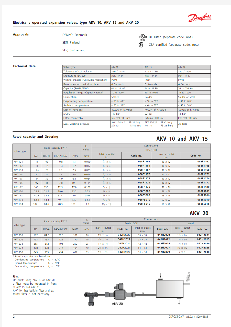
Electrically operated expansion valves,type AKV 10, AKV 15 and AKV 20
HCFC and Non-flamable HFC The valve requires no adjustment Wide regulation range Replaceable orifice assembly
Both expansion valve and solenoid valve. Wide range of coils for d.c. and a.c.
Features
AKV are electrically operated expansion valves designed for refrigerating plant. The AKV valves can be used for HCFC and HFC, R744 refrigerants. The AKV valves are normally controlled by a con-troller from Danfoss’ range of ADAP- KOOL? con-trollers.
The AKV valves are supplied as a component pro-gramme, as follows: Separate valve
Separate coil with terminal box or cable
Spare parts in the form upper part, orifice and filter
The individual capacities are indicated with a number forming part of the type designation. The number represents the size of the orifice of the valve in question. A valve with orifice 3 will for example be designated AKV 10-3. The orifice assembly is replaceable.
The AKV 10 valves covers a capacity range from 0.6 kW to 14 kW (R404A/R507) and are divided up into 7 capacity ranges.
The AKV 15 valves cover a capacity range from 14 kW to 85 kW (R404A/R507) and are divided up into 4 capacity ranges.
AKV 15 valves can be used for cold rooms.The AKV 20 valves cover a capacity range from 56 kW to 530 kW (R404A/R507) and are divided up into 5 capacity ranges.
The AKV 20 can be used for water chiller units.
DKRCC.PD.VA1.A5.02 / 520H6588
2Electrically operated expansion valves, type AKV 10, AKV 15 and AKV 20
Technical data
Rated capacity and Ordering
Condensing temperature t c = 32°C Liquid temperature t l = 28°C Evaporating temperature t e =
5°C
Filter.
On plants using AKV 15 or AKV 20 a filter must be mounted in front of AKV 15 and AKV 20.
AKV 10 has built-in filter and ex-ternal filter is not necessary.
DEMKO, Denmark SETI, Finland
SEV, Switzerland
UL listed (separate code. nos.) CSA certified (separate code. nos.)
Approvals
DKRCC.PD.VA1.A5.02 / 520H65883
Electrically operated expansion valves, type AKV 10, AKV 15 and AKV 20
Filter: Contents:
Code no. 068F054010 pcs. filters
10 pcs. Al. gaskets
Upper part: Contents: Code no. 068F05411 pc. armature ass.
1 pc. armature tube 1 pc. Al. gasket
Gasket for upper part: Contents:
Code no. 068F054925 pcs. Cu/Tn gaskets
Spare parts AKV 10
AKV 15
AKV 20Filter: Contents:
Code no. 068F054010 pcs. filters
10 pcs. Al. gaskets
Upper part: Contents:Code no. 068F50451 pc. armature ass.
1 pc. armature tube 1 pc. Al. gasket
Gasket for upper part: Contents:
Code no. 068F054925 pcs. Cu/Tn gaskets
Gasket set: Contents:
Code no. 042H0160Complete gasket set for new and old
valves
Upper part: Contents:Code no. 068F50451 pc. armature ass.
1 pc. armature tube 1 pc. Al. gasket
Gasket for upper part: Contents:
Code no. 068F0549
25 pcs. Cu/Tn gaskets
Orifice
Piston
Gasket set:Contents:
Code no. 068F526330 pcs. O-rings 10 pcs. Cu. gasket
10 pcs. gasket
Piston
Orifice set
Electrically operated expansion valves, type AKV 10, AKV 15 and AKV 20
DKRCC.PD.VA1.A5.02 / 520H6588
4
DKRCC.PD.VA1.A5.02 / 520H65885
Electrically operated expansion valves, type AKV 10, AKV 15 and AKV 20
Capacity
The evaporator capacity used must be corrected, if the subcooling deviates from 4 K.
Use the actual correction factor indicated in the table.
Multiply the evaporator capacity by the correc-tion factor to obtain the corrected capacity.
Correction for subcooling
DKRCC.PD.VA1.A5.02 / 520H6588
6Electrically operated expansion valves, type AKV 10, AKV 15 and AKV 20
Capacity
(continued)
The evaporator capacity used must be corrected, if the subcooling deviates from 4 K.
Use the actual correction factor indicated in the table.
Multiply the evaporator capacity by the correc-tion factor to obtain the corrected capacity.
Correction for subcooling
DKRCC.PD.VA1.A5.02 / 520H65887
Electrically operated expansion valves, type AKV 10, AKV 15 and AKV 20
Capacity (continued)
Correction for subcooling
The evaporator capacity used must be corrected, if the subcooling deviates from 4 K.
Use the actual correction factor indicated in the table.
Multiply the evaporator capacity by the correc-
tion factor to obtain the corrected capacity.
DKRCC.PD.VA1.A5.02 / 520H6588
8Electrically operated expansion valves, type AKV 10, AKV 15 and AKV 20
To obtain an expansion valve that will function correctly under different load conditions it is necessary to consider the following points when sizing the valve:
These points must be dealt with in the following sequence:
1) Evaporator capacity
2) Pressure drop across the valve 3) Correction for subcooling
4) Correction for evaporating temperature 5) Determination of valve size
6) Correctly dimensioned liquid line
Valve sizing
1) Evaporator capacity
The evaporator capacity is found in the specifi-cations from the evaporator supplier.
2) Pressure drop across the valve
The pressure drop across the valve directly determines the capacity and must therefore be considered.
The pressure drop across the valve is normally calculated as the condensing pressure less the evaporating pressure and sundry other pressure drops in the liquid line, distributor, evaporator, etc.It is indicated in the following formula:?p valve = p c – (p e + ?p 1 + ?p 3 + ?p 4)?p 3 pressure drop across the distributor system ?p 4 pressure drop across the evaporator
Note!
distributor system must be calculated on the basis of the valve’s max. capacity, as the valve operates with pulse-width modulation.Example of calculation of pressure drop across a valve:
Refrigerant: R22
Condensing temperature: 35°C (p c = 13.5 bar)Evaporating temperature: 0 - 6°C (p e = 4.1 bar)?p 1 = 0.2 bar ?p 3 = 0.8 bar ?p 4 = 0.1 bar
This will give you the following equation:?p valve = p c – (p e + ?p 1 + ?p 3 + ?p 4) = 13.5 – (4.1 + 0.2 + 0.8 + 0.1) = 8.3 bar The found value for “pressure drop across the valve” is used later in the section “Determination of valve size”.
DKRCC.PD.VA1.A5.02 / 520H65889
Electrically operated expansion valves, type AKV 10, AKV 15 and AKV 20
3) Correction for subcooling
The evaporator capacity used must be cor-rected, if the subcooling deviates from 4 K. Use the actual correction factor indicated in the table.
Multiply the evaporator capacity by the correc-tion factor to obtain the corrected capacity.
Valve sizing (continued)
The corrected capacity is used in the section “De-termination of valve size”.Example of corection:Refrigerant: R22
Evaporator capacity Q e : 5 kW Subcooling: 10 K
Correction factor according to the table = 0.94Corrected capacity = 5 × 0.94 = 4.7 kW.Note: Too little subcooling may cause flash gas.
4) Correction for evaporating temperature (t e ) To obtain a correctly dimensioned valve it is important that the application is considered. Depending on the application, the valve should have an overcapacity enabling it to cope with the extra amount of refrigeration needed during certain periods, e.g. during the defrost recovery process.
The valve’s opening degree should therefore be between 50 and 75% when regulating. In this way it is ensured that the valve has a sufficiently wide regulation range, so that it can manage changed loads at or near the normal working point.
Correction factors based on the evaporating tem-
perature are indicated below:
5) Determination of valve size
When the valve size meeting the required ca-pacity is selected it is important to note that the capacity indications are the valve’s rated capacity, i.e. when the valve is 100% open.
In this section we tell you how the valve’s size is determined.
There are three factors that have an influence on the choice of the valve:
- the pressure drop across the valve - the corrected capacity (correction for subcooling)
- the corrected capacity for evaporating temperature
The three factors have been described earlier in this section on dimensioning. When these three factors have been established, the selec-tion of the valve can be made:
- First you multiply the “corrected capacity” by a value stated in the table.
- Use the new value in the capacity table in com-bination with the pressure drop value.- Now select the valve size.
Example of selection of valve
Use as starting point the two earlier mentioned examples, where the following two values have been obtained:?p valve = 8.3 bar Q e corrected = 4.7 kW
The valve should be used in a coldroom. Conse-quently, 1.25 should be selected as “correction factor for the evaporating temperature”.
The dimensioned capacity will then be: 1.25 x 4.7 kW = 5.88 kW.
Now select a valve size from one of the capacity tables.
With the given values ?p valve = 8.3 bar and a ca-pacity of 5.88 kW, select the valve size for AKV 10-5.
This valve will have a capacity of approx. 7 kW.
Electrically operated expansion valves, type AKV 10, AKV 15 and AKV 20
Valve sizing(continued)6) Correctly dimensioned liquid line
To obtain a correct supply of liquid to the AKV
valve, the liquid line to the individual AKV valve
must be correctly dimensioned.
The liquid flow rate should not exceed 1 m/sec. This must be observed on account of the pressure drop in the liquid line (lack of subcooling) and pulsations in the liquid line.
Dimensioning of the liquid line must be based on the capacity of the valve at the pressure drop with which it is operating (cf. capacity table), and not on the evaporator’s capacity.
DKRCC.PD.VA1.A5.02 / 520H6588 10
AKV 15
AKV 20
AKV 10
DKRCC.PD.VA1.A5.02 / 520H658811
Electrically operated expansion valves, type AKV 10, AKV 15 and AKV 20
Design
1. I nlet
2. Outlet
3. Orifice
4. Filter
5. Valve seat
6. Armature
7. Copper gasket 8. Coil
9. DIN plug 12. O-ring
1. I nlet
2. Outlet
3. Orifice
4. Piston assembly 7. Coil
8. Armature 9. Pilot orifice 10. Filter 11. Cover
12. Valve body 13. Spring
14. Orifice assembly
1. I nlet
2. Outlet
3. Orifice
4. Valve seat
5. Filter
6. Pilot orifice
7. O-ring
8. Coil
9. Terminal box
AKV 15
DKRCC.PD.VA1.A5.02 / 520H6588
12Electrically operated expansion valves, type AKV 10, AKV 15 and AKV 20
The valve capacity is regulated by means of pulse-width modulation. Within a period of six seconds a voltage signal from the controller will be transmitted to and removed from the valve coil. This makes the valve open and close for the flow of refrigerant.
The relation between this opening and closing time indicates the actual capacity. If there is an intense need for refrigeration, the valve will remain open for almost all six seconds of the period. If the re-quired amount of refrigeration is modest, the valve will only stay open during a fraction of the period. The amount of refrigeration needed is de-termined by the controller.
When no refrigeration is required, the valve will remain closed and thus function as a solenoid valve.
Function
Dimensions and weights
AKV 10 solder
AKV 20
? Danfoss A/S (AC-MCI sw), 2012.07 DKRCC.PD.VA1.A5.02 / 520H658813
Dimensions and weights
(continued)