amesim simulink联合仿真
- 格式:pdf
- 大小:463.62 KB
- 文档页数:34
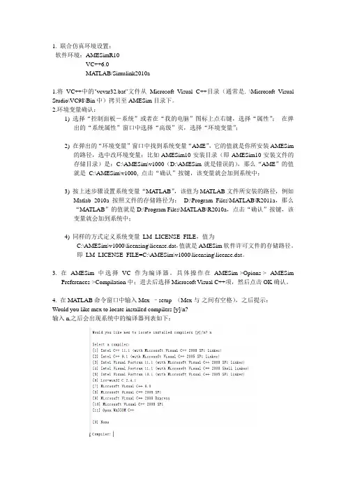
1. 联合仿真环境设置:软件环境:AMESimR10VC++6.0MA TLAB/Simulink2010a1.将VC++中的"vcvar32.bat"文件从Microsoft Visual C++目录(通常是. \Microsoft Visual Studio\VC98\Bin中)拷贝至AMESim目录下。
2.环境变量确认:1) 选择“控制面板-系统”或者在“我的电脑”图标上点右键,选择“属性”;在弹出的“系统属性”窗口中选择“高级”页,选择“环境变量”;2) 在弹出的“环境变量”窗口中找到系统变量“AME”,它的值就是你所安装AMESim的路径,选中改环境变量;比如AMESim10安装目录(即AMESim10安装文件的存储目录)是:C:\AMESim\v1000(D:\AMESim就是错误的),那么“AME”的值就是C:\AMESim\v1000, 点击“确认”按键,该变量就会加到系统中;3) 按上述步骤设置系统变量“MATLAB”,该值为MA TLAB文件所安装的路径,例如Matlab 2010a按照文件的存储路径为:D:\Program Files\MATLAB\R2011a,那么“MA TLAB”的值就是D:\Program Files\MATLAB\R2010a,点击“确认”按键,该变量就会加到系统中;4) 同样的方式定义系统变量LM_LICENSE_FILE,值为C:\AMESim\v1000\licensing\license.dat,值就是AMESim软件许可文件的存储路径。
即LM_LICENSE_FILE=C:\AMESim\v1000\licensing\license.dat。
3. 在AMESim中选择VC作为编译器。
具体操作在AMESim->Opions-> AMESimPreferences->Compilation中;进去后选择Microsoft Visual C++项,然后点击OK确认。
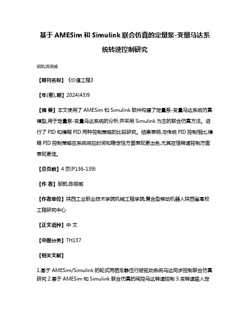
基于AMESim和Simulink联合仿真的定量泵-变量马达系
统转速控制研究
邬凯;陈朋威
【期刊名称】《价值工程》
【年(卷),期】2024(43)9
【摘要】本文使用了AMESim和Simulink软件构建了定量泵-变量马达系统仿真模型,用于定量泵-变量马达系统的分析,并采用Simulink为主的联合仿真方法。
进行了PID和模糊PID两种控制策略的比较研究。
结果表明,与传统PID控制相比,模糊PID控制策略在系统响应时间和稳定性方面表现更出色,尤其在恒转速控制方面表现更佳。
【总页数】4页(P136-139)
【作者】邬凯;陈朋威
【作者单位】陕西工业职业技术学院机械工程学院;复合型移动机器人陕西省高校工程研究中心
【正文语种】中文
【中图分类】TH137
【相关文献】
1.基于AMESim/Simulink的轮式两栖车静压行驶驱动系统马达同步控制联合仿真研究
2.基于AMESim和Simulink联合仿真的阀控马达转速控制
3.变转速输入定
量泵-恒转速输出变量马达系统恒转速控制方法研究4.基于AMESim和Simulink 联合仿真的马达转速自适应控制
因版权原因,仅展示原文概要,查看原文内容请购买。
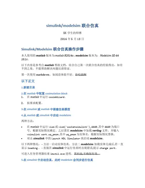
simulink/modelsim联合仿真XX学生的师傅2016年5月13日Simulink/Modelsim 联合仿真操作步骤本人使用的matlab版本为:matlab R2014a ; modelsim版本为:Modelsim SE-64 10.1c。
以下内容是参考自matlab帮助文档,结合自己第一次联合仿真的经验得出,如有不到之处,不能帮助解决问题还请原谅。
第一次使用markdown,如阅读体验不好,你咬我啊以下正文1.新建目录2.在matlab中配置cosimulation block1.在matlab中运行cosimWizard。
2.按要求配置。
3.在simulink或matlab中搭建仿真模型4.从matlab或simulink中启动modelsim两种方法:•在matlab中运行vism或vism('socketsimulink'),4449 ,其中4449为端口号,根据实际情况确定。
之后需在modelsim中加载verilog文件,并输入vsimulink work.uq_pmsm ,其中uq_pmsm为实体名,根据实际情况替换。
•双击simulink中的Launch HDL Simulator块启动modelsim。
以下两种情况: - 方法一启动实体仿真、方法二modelsim加载实体完成后,若一直显示loading。
- 直接在simulink中运行仿真时出现错误,提示change port。
可进入任务管理器结束lmutil.exe进程。
黑科技,不确保有效。
5.在simulink中启动仿真,此时modelsim会同步进行仿真。
目录摘要 (1)0 引言 (1)1 联合仿真技术 (2)1.1 联合仿真技术的特点与应用 (2)1.2 联合仿真技术的实现途径 (2)2 联合仿真接口技术 (3)2.1 系统环境配置 (3)2.2 系统编译器配置 (3)3 联合仿真应用举例 (5)4 结论 (8)致谢 (8)参考文献 (9)AMESim与Matlab_Simulink联合仿真技术机械电子系0802班李敏M200870228摘要:根据AMESim与Matlab/Simulink软件各自的特点,对两者联合仿真技术进行了研究,解决了联合仿真的接口与实现问题,并把该技术应用于电液位置伺服系统的仿真,取得了良好的效果。
关键词:AMESim;Matlab/Simulink;联合仿真;接口Abstract:United Matlab/Simulink technique with AMESim and Matlab/Simulink was discussed based on their own characteristics. The problem of their interface and realization were solved. As an applied example, Matlab/Simulink of electro hydraulic servo-system was shown. Good results were achieved.Keywords:AMESim;Matlab/Simulink;United simulation;Interface0 引言传统的设计方法往往是通过反复的样品试制和试验来分析该系统是否达到设计要求,结果造成大量的人力和物力投入在样品的试制和试验上。
随着计算机仿真技术的发展,在工程系统的软件设计开发中,大量地采用了数值成型的方法,即通过建立系统的数值模型,利用计算机仿真使得大量的产品设计缺陷在物理成型之前就得到了处理,从而可以使企业在最短的时间、以最低的成本将新产品投放到市场。
论文:基于A M E S i m与M a t l a b\S i m u l i n k联合仿真技术的接口与应用研究基于AMESim与Matlab\Simulink联合仿真技术的接口与应用研究摘要:根据AMESim与Matlab\Simulink软件各自的特点,对两者联合仿真技术进行了研究,解决了联合仿真的接口与实现问题,并把该技术应用于电液位置伺服系统,取得了良好效果关键词:AMESim,Matlab\Simulink,联合仿真,电液伺服系统1 引言法国lmagine公司开发的AMESim是当今领先的流体,传动系统和液压/机械系统建模,仿真及动力学分析软件.它为用户提供了一个系统工程设计的完整平台,可以建立复杂的多学科领域系统的数学模型,并在此基础上进行仿真计算和深入的分析.然而,不存在一种仿真软件平台能够提供工程设计所需要的所有功能。
AMESim作为多学科领域系统仿真设计的平台提供了丰富的与其他软件的接口。
基于Matlalb平台的Simulink是动态系统仿真领域中著名的仿真集成环境,它在众多领域得到广泛应用。
Simulink 借助Matlalb的计算功能,可方便地建立各种模型、改变仿真参数,很有效地解决仿真技术中的问题。
AMESim作为一个完整的系统工程仿真平台,Simulink作为事实上的控制系统设计的标准平台。
点对点的AMESim-Simulink接口提供了一个使用便捷和行之有效的工具用于AMESim的被控对象模型和控制系统模型之间的耦合分析。
同时利用了AMESim和Simulink的最佳功能,避免了不同平台之间复杂模型的重建。
2 联合仿真设置与实现2.1 联合仿真设置1 将VC++中的"vcvar32.bat"文件从Microsoft Visual C++目录(通常是.\Microsoft Visual Studio\VC98\2 设置环境变量:我的电脑-〉属性-〉高级-〉环境变量。
2008年6月第36卷第6期机床与液压MACH I N E T OOL &HY DRAUL I CSJun 12008Vol 136No 16收稿日期:2007-09-03基金项目:四川省重点学科重点实验室建设项目(Z01336)作者简介:王康康(1981—),男,浙江浦江人,在读研究生,主要研究方向:汽车电子控制技术。
电话:013550397278,E -mail:p jcucu mber@1631com 。
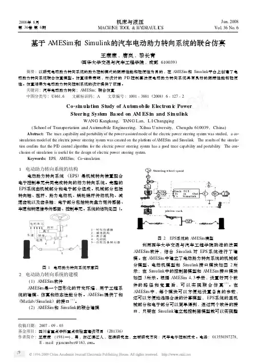
基于A MESim 和Simulink 的汽车电动助力转向系统的联合仿真王康康,唐岚,黎长青(西华大学交通与汽车工程学院,成都610039)摘要:以研究电动助力转向系统的助力控制模式的跟踪性能和轻便性为目的,在AMESi m 和Si m ulink 平台上创建了电动助力转向系统联合仿真模型。
仿真结果表明,所设计的P I D 控制算法使电动助力转向系统具有良好的跟踪性能和轻便性。
仿真结果为电动助力转向控制系统的设计提供了依据。
关键词:汽车电动助力转向;AMESi m ;联合仿真中图分类号:U46116 文献标识码:A 文章编号:1001-3881(2008)6-127-2Co 2si m ul a ti on Study of Autom ob ile Electron i c PowerSteer i n g System Ba sed on AM ES i m and S i m uli n kWANG Kangkang,T ANG Lan,L I Changqing(School of Trans portati on and Aut omobile Engineering,Xihua University,Chengdu 610039,China )Abstract:The trace capability and portability of the power 2assisted mode of the electric power steering syste m was studied,a co 2si m ulati on model of the electric power steering syste m was created on the p latfor m of AMESi m and Si m ulink .The results of the si m ula 2ti on confir m that the P I D contr ol algorith m f or the electric power steering syste m has a good trace capability and portability .The con 2clusi on of si m ulati on is useful f or the design of electric power steering syste m.Keywords:EPS;AMESi m ;Co 2si m ulati on1 电动助力转向系统的结构电动助力转向系统(EPS )是机械转向装置配合电子控制单元共同完成转向的动力转向系统。
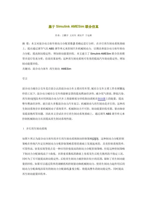
基于SimulinkAMESim联合仿真作者:王鹏宇王庆年胡安平于远彬摘要:本文对混合动力客车制动力分配系数β的确定进行分析。
在并行再生制动系统基础上,提出通过调节气压ABS调节单元来控制汽车机械制动力,以期改善混合动力客车制动力分配,提高制动稳定性,增加制动能量回收。
本文建立了Simulink-AMESim联合仿真模型并进行仿真分析,仿真结果表明:这种再生制动系统可有效的提高汽车制动稳定性,增加制动能量回收。
关键词:混合动力客车再生制动AMESim引言混合动力城市公交车是目前公认的混合动力车主要应用车型,城市公交车主要工作在频繁起停的工况下,混合动力城市公交车将能够显著的提高燃油经济性,减少尾气排放,降低污染。
再生制动[1]技术应用到混合动力汽车上将能够部分回收制动消耗在制动器上的能量,提高整车燃油经济性。
就目前大多数混合动力汽车而言,机械制动与再生制动是并行的,这种再生制动系统存在着机械制动子系统常开,机械制动力不可控,制动能量回收有限,驱动轴容易提前抱死等问题。
因此本文尝试在并行再生制动系统基础上,通过调节ABS调节单元来控制机械制动力从而提高再生制动系统性能。
1并行再生制动系统如图1所示为混合动力客车的并行再生制动系统制动控制策略[2][3],这种制动力分配控制策略在传统汽车定比例制动力分配控制策略思想的基础上发展起来的,具有控制系统简单,可靠性高,容易实现等优点是一种应用价值很高的制动力分配控制策略。
但是这种控制策略下制动力分配曲线高于I曲线,在附着系数低的路面上容易发生后轮先抱死的不稳定工况,同时为了尽可能提高制动稳定性,后轮再生制动力被控制在较小的范围,限制了再生制动能量的回收。
如果可以通过简单的调解机构控制驱动轴机械制动力,使再生制动力起作用后的制动力分配曲线沿原有的制动力分配曲线β线分配。
将提高整车的制动稳定性,同时提高再生制动能量回收率。
2 混合动力客车制动力分配对于混合动力客车而言,后轴为驱动轴,其制动力由机械制动力与再生制动力共同提供。

Simulink与AMSIM联合仿真的方法虽然随着新材料、电机技术、控制学和先进制造技术等的发展,出现了用以取代目前所依赖的功率液压传动的功率电传技术,但是在现阶段,液压伺服作动系统仍然占据航空作动系统的主导地位。
主要原因是液压伺服作动系统具有其它伺服作动系统无法比拟的优势,具有容易得到大功率输出、高功率/重量比、响应快和低俗特性好的特点。
航空液压作动系统是目前飞机上最成熟的液压作动方式,大多直接采用飞机的中央液压源提供的恒压油,通过(伺服)阀来控制执行机构的双腔流量完成指令动作,精度高、响应快。
航空也要作动系统根据其发展历程一般分为以下四类:液压助力器、电液指令作动器、复合式伺服作动器和直接驱动阀式伺服作动器。
本文将主要对其关键技术进行深入分析,并提出关键技术的解决途径。
1 建模仿真技术由于对航空液压作动系统自身结构比较复杂,对其自身的性能要求比较高,需要满足包括输出载荷、中立位置、额定行程、最大行程、行程余量、额定速度、最大速度、极限载荷、主控阀剪切力、门限、位置精度和滞环等的静态特性,满足包括频率响应和阶跃响应的动态特性,以及稳定性和阻抗特性要求。
银次,在研制航空液压作动系统的过程中,对其进行建模仿真非常重要。
通过仿真,可以对所设计的作动器性能有全面的了解,便于改进和完善设计。
传统的建模仿真分析手短一般采用数学推到加Simulink仿真的方式进行。
Simulink是美国Match Works公司开发的MA TLAB软件的可视化仿真环境,具有丰富的线性/非线性、连续/离散等控制系统仿真功能模块,具备神经网络、模糊控制等一系列先进的智能控制工具箱,非常适合进行航空液压作动系统的建模与分析,但其前提是基于用户建立的数学模型和其自身提供的结构参数化的功能模块。
而这已无法满足现在对仿真高精度和高准确度的要求。
而且Simulink本身没有专门针对液压流体仿真的工具箱,用户使用时要自己建立模型。
AMESim是法国Imagine公司推出的基于功率键合图的液压/机械系统建模、仿真机动力学分析软件,采用图形化的物理建模方式,具有复杂液压元件结构参数化的功能模块,也同样非常适合进行航空液压作动系统的结构参数化建模与分析,但是他的控制系统仿真功能模块相对较少,不具备神经网络、模糊控制等一系列先进的智能控制工具箱。
基于AMESim与Simulink/Stateflow的汽车ABS联合建模与仿真研究汽车ABS系统是现代汽车安全性能的重要组成部分,它能够在紧急刹车时避免车轮打滑和打滑过度,保证驾驶员和乘客的人身安全。
为了更好地研究汽车ABS系统,需要进行建模与仿真研究。
本文将介绍一种基于AMESim与Simulink/Stateflow联合建模的汽车ABS系统研究方法。
首先,我们需要了解AMESim和Simulink/Stateflow的基本概念。
AMESim是一种以物理原理为基础的多领域仿真软件,可用于建立液压、气动、热流等系统的数学模型,并通过仿真来对其性能进行分析。
Simulink是一种用于建立和仿真动态系统的可视化建模工具,Stateflow则是用于建立和仿真离散事件动态系统的建模工具,它们可以相互集成,进行联合建模和仿真。
接下来,本文将介绍联合建模和仿真ABS系统的过程。
首先,需要建立车辆动力学模型,包括车轮、刹车系统和悬挂系统。
然后,需要将车轮动力学模型与刹车系统模型相结合,建立汽车ABS系统模型。
在此基础上,还需要建立控制器模型,用于确保系统能够在各种情况下正常运行。
对于车轮模型,可借助AMESim进行建模。
首先将轮胎和车轮组合在一起,导入力学特性和减震特性,建立轮胎和车轮的物理特征模型。
然后,将车轮与刹车系统相结合,建立刹车系统的物理模型。
在刹车系统中,我们需要考虑刹车片接触和离开刹车盘时的特性,以及刹车盘的温度变化等因素。
对于控制器模型,可以利用Simulink/Stateflow进行建模。
首先,需要将在汽车ABS系统中充当传感器的各种设备模型输入到模型中。
然后,需要建立控制系统模型,包括基于压力、时间和速度等因素的控制器模型和驾驶员刹车工况判断模型。
最后,需要将控制系统模型与车轮模型和刹车系统模型相结合,建立完整的汽车ABS系统模型。
完成ABS联合建模后,我们可以通过仿真来测试汽车ABS系统的性能。
AMESim与MATLAB\Simulink联合仿真技术及在发动机主动隔振中的应用作者:肖勇摘要:介绍了AMESim 软件与MATLAB\Simulink 的接口技术,并使用AMESim 与MATLAB\Simulink 对发动机主动隔振进行了联合仿真,分析了主动以及被动隔振的隔振效果,为主动控制提供了新的设计思路。
关键词:AMESim ,MATLAB\Simulink ,联合仿真,主动隔振,LQR1. AMESim 软件介绍以及与MATLAB\Simulink的接口技术AMESim(Advanced Modeling Environment for Simulation of Engineering Systems ) 是1995 年由法国IMAGINE 公司开发的一个图形化的开发环境,用于工程系统的建模、仿真和动态性能分析。
AMESim仿真模型的建立扩充或改变都是通过图形界面(GUI)来进行的,使用者不用编制任何程序代码。
该软件采用了鲁棒性极强的智能求解器,自动选择最佳的积分算法,从而缩短了仿真时间、提高了仿真精度。
此外,AMESim与多种软件的具有接口。
AMESim 提供了与Excel、Matlab、MATLAB\Simulink 和ADAMS 等软件的接口,可方便地与这些软件进行联合仿真。
为了实现联合仿真需要在Windows2000 或更高级的操作系统下安装VisualC++6.0、AMESim4.0 和MATLAB6.1(或者三种软件的更高版本),并进行以下设置:1) 设置环境变量。
打开“控制面板”,选择“系统”菜单,然后选择“高级”里的“环境变量”。
在“系统变量”栏新建变量,变量名为“MATLAB”,变量值为MATLAB 的安装路径,如:“C:\MATLAB6p5”;确认在系统变量“Path” 中包括Windows 安装路径“C:\WINNT” 如果没有请添加上。
2) AMESim工作环境的设置。
软件准备:MATLAB2016bAMEsim2020.2Visual studio 2013软件不宜过新。
上面是恒仔使用的、联合成功的版本。
步骤:一:复制文件将D:\Program Files (x86)\Microsoft Visual Studio 12.0\VC\bin下的nmake.exe 、vcvars32.bat和D:\Program Files (x86)\Microsoft Visual Studio 12.0\VC\bin\amd64下的vcvars64.bat复制到D:\Program Files\Simcenter\2020.2\Amesim中覆盖。
(全文所提到路径皆为自己软件的安装路径,可根据自己安装情况更改)二:环境配置在安装完Visual Studio 2013、Amesim 2020.2 、Matlab 2016b之后,需要配置环境变量。
在windows桌面,右键“计算机”-“属性”-“高级系统设置”-“环境变量”里添加用户变量和系统变量。
1、用户变量添加变量名:HOME,变量值:D:\添加变量名:MATLAB,变量值:D:\Program Files\MATLAB\R2016b2、双击Path变量,添加:配置完成后,重启电脑,以使用户变量和系统变量生效。
三、软件设置:1、首先打开Matlab 2016b,在命令窗口输入:mex -setup将C和C++编译器都设置为Visual C++ 2013.2、打开Amesim2020.2 ,进入Tools-Preferences-Compilation,将Active Compiler设置为Microsoft Visual C++ (64bit)。
软件配置完成。
四、联合仿真例程运行在Amesim 2020.2-Help-Help里,输入simulink,打开“Hybrid_bus_steps_simulink”例程:点击Open this demo,下面一串链接,将其复制到指定目录并打开:点击Amesim 2020.2-Tools-MATLAB®,它会自动打开MATLAB2017b,并自动添加AMESIM的相关路径到MATLAB PATH里,然后它会自动打开Hybrid_bus_steps_simulink.mdl。
收稿日期:2019-07-23基于AMESim 和Simulink 联合仿真的阀控马达转速控制毛雨露(长安大学工程机械学院,西安710000)摘要:为了更好地控制阀控马达系统的转速,运用AMESim 和Simulink 软件建立了阀控液压马达系统的数学模型,并进行联合仿真。
同时对液压马达的调速控制采用参数自整定的模糊自适应PID 控制策略来实现。
仿真结果表明,与传统PID 控制相比,在阀控马达调速系统中,模糊自适应PID 控制策略下的系统响应速度更快,超调量小,抗干扰能力更强,有更好的鲁棒性。
关键词:阀控马达;联合仿真;模糊自适应PID 控制;调速控制中图分类号:TH137文献标志码:A文章编号:1009-9492(2020)02-0093-03Speed Control of Valve-controlled Motor Based on AMESim andSimulink SimulationMAO Yulu(School of Engineering Machinery ,Chang ′an University ,Xi ′an 710000,China )Abstract:In order to better control the speed of the motor ,the mathematical model of the valve-controlled hydraulic motor system was established byusing the combined simulation of AMESim and Simulink ,and the fuzzy PID control strategy with self-tuning parameters was adopted to realize the speed control of the hydraulic motor.The simulation results show that compared with the traditional PID control ,the system under the fuzzy PIDcontrol strategy has faster response speed ,smaller overshoot ,stronger anti-interference ability and better robustness.Key words:valve-controlled motor ;combined simulation ;fuzzy PID control ;speed controlDOI:10.3969/j.issn.1009-9492.2020.02.025第49卷第02期Vol.49No.02机电工程技术MECHANICAL &ELECTRICAL ENGINEERING TECHNOLOGY毛雨露.基于AMESim 和Simulink 联合仿真的阀控马达转速控制[J ].机电工程技术,2020,49(02):93-95.0引言随着液压伺服技术的快速发展,阀控马达系统由于其响应频率高、控制精度准、调节时间短、动态性能好被广泛应用在工程机械领域,尤其是功率小、响应速度快的系统[1]。
Simulink与AMSIM联合仿真的方法虽然随着新材料、电机技术、控制学和先进制造技术等的发展,出现了用以取代目前所依赖的功率液压传动的功率电传技术,但是在现阶段,液压伺服作动系统仍然占据航空作动系统的主导地位。
主要原因是液压伺服作动系统具有其它伺服作动系统无法比拟的优势,具有容易得到大功率输出、高功率/重量比、响应快和低俗特性好的特点。
航空液压作动系统是目前飞机上最成熟的液压作动方式,大多直接采用飞机的中央液压源提供的恒压油,通过(伺服)阀来控制执行机构的双腔流量完成指令动作,精度高、响应快。
航空也要作动系统根据其发展历程一般分为以下四类:液压助力器、电液指令作动器、复合式伺服作动器和直接驱动阀式伺服作动器。
本文将主要对其关键技术进行深入分析,并提出关键技术的解决途径。
1 建模仿真技术由于对航空液压作动系统自身结构比较复杂,对其自身的性能要求比较高,需要满足包括输出载荷、中立位置、额定行程、最大行程、行程余量、额定速度、最大速度、极限载荷、主控阀剪切力、门限、位置精度和滞环等的静态特性,满足包括频率响应和阶跃响应的动态特性,以及稳定性和阻抗特性要求。
银次,在研制航空液压作动系统的过程中,对其进行建模仿真非常重要。
通过仿真,可以对所设计的作动器性能有全面的了解,便于改进和完善设计。
传统的建模仿真分析手短一般采用数学推到加Simulink仿真的方式进行。
Simulink是美国Match Works公司开发的MA TLAB软件的可视化仿真环境,具有丰富的线性/非线性、连续/离散等控制系统仿真功能模块,具备神经网络、模糊控制等一系列先进的智能控制工具箱,非常适合进行航空液压作动系统的建模与分析,但其前提是基于用户建立的数学模型和其自身提供的结构参数化的功能模块。
而这已无法满足现在对仿真高精度和高准确度的要求。
而且Simulink本身没有专门针对液压流体仿真的工具箱,用户使用时要自己建立模型。
AMESim是法国Imagine公司推出的基于功率键合图的液压/机械系统建模、仿真机动力学分析软件,采用图形化的物理建模方式,具有复杂液压元件结构参数化的功能模块,也同样非常适合进行航空液压作动系统的结构参数化建模与分析,但是他的控制系统仿真功能模块相对较少,不具备神经网络、模糊控制等一系列先进的智能控制工具箱。
link
冯 曼 胡国星
中国飞行试验研究院
冯曼,女,研究生
电影像测量。
高升力系统是通过增加飞机飞行中的升力,改善飞机飞行起降性能,提升飞机飞行安全。
高升力加载系统在研究和检验高升力系统性能方面起着至关重要的作用,它能将传统的全实物试验转变为实验室条件下半实物的预测性试验。
但由于高升力加载系统涉及到多学科的综合内容,而且在实际工程中,系统结构庞大、设计周期漫长、使用不具备重
图3 耦合系统联合仿真AMESim 模型
图4 系统联合仿真matlab/simulink 模型
图5(a)
图5(b)
器算法。
在配置完模型参数后,就可以点击start simulation
按钮,此时AMESim 与Simulink 便进入联合系统仿真状态。
建立联合仿真模型按照构建 AMESim 模型的步骤,根据电液伺服加载模
型的物理关系,依次完成草图模式( Sketch mode)、子模型模式( Submodel mode)、参数模式( Parameter mode)和运行模式( Run mode)四步,完成其 AMESim 建模,根据电液伺服加载系统的控制结构,在 Simulink 里。
AMESim-Simulink联合仿真安装步骤2014-7北京科技大学机械工程学院 MW1.软件版本说明本文安装版本为Visual Studio 2008、MATLAB r2009a、AMESim r13,推荐都使用英文版。
2.辅助软件要求若要使用AMESim与Simulink的接口,则需要安装Microsoft Visual C++编译器,一般是先安装C++编译器,然后安装Matlab,最后安装AMESim。
将C++编译器安装目录下如D:\Program Files\Microsoft Visual Studio 9.0\VC\bin目录中的nmake.exe文件和vcvars32.bat 文件拷贝至AMESim 安装目录,如D:\AMESim\v1300下。
启动AMESim并确认AMESim使用的是MS C++编译器,从AMESim 菜单下选择Tools、Options,然后选择AMESim Preferences,按下图界面设置AMESim编译器为C++编译器:在第一次使用AMESim和Simulink接口时,请在Matlab命令行窗口输入以下命令以确认其所使用的编译器:Mex -setup(注意mex和-之间有空格!)然后在提示中输入Y,2,Y选择对应的C++编译器编号并确认。
在Matlab界面,加入如下两个路径(%AME%指AMESim的安装路径,如D:\AMESim\v1300):%AME%\scripting\matlab\amesim%AME%\interfaces\sl2ame3.环境变量环境变量分为用户变量(U)和系统变量(S),注意区分!变量值要根据软件安装的盘符路径自己调整。
例如,我把MATLAB安装在D:\MATLAB\R2009a,把AMESim安装在D:\AMESim\v1300在用户变量中添加HOME=D:\MATLAB =D:\MATLAB\R2009a在系统变量中添加AME=D:\AMESim\v1300(这个一般都有的,不需要自己添加)MATLAB =D:\MATLAB\R2009aPath=D:\Program Files\Microsoft Visual Studio 9.0;D:\AMESim\v1300;D:\AMESim\v1300\win32;D:\AMESim\v1300\sys\mingw32\bin;D:\AMESim\v1300\sys\mpich\ mpd\bin;D:\AMESim\v1300\sys\cgns;%SystemRoot%\system32;%SystemRoot%;%SystemRoot%\System32\Wbem;D:\ MATLAB\R2009a\bin\win32;C:\WINDOWS\system32;C:\WINNT4.联合仿真设置成功的标志是可以运行Help→AMESim demo help→Platform→MIL/SIL/HIL and Real-Time下的范例5.注意事项(1)VS推荐使用2008版,本人试过2010版,但失败了,注意要使用英文版。
AMESim—MATLAB(64位)联合仿真设置详细步骤说明:现以AMESimR12、MATLAB2014b为例说明,其他版本类似。
1、版本要求2、辅助软件VS2013若要使用 AMESim 与 Simulink 的接口,则需要在本机安装编译器,高版本软件需要高版本的编译器,这里以VS2013为例设置。
一般推荐先安装VS编译器,然后安装 Matlab,最后安装 AMESim的顺序。
若后安装VS编译器,将VS编译器安装目录下如 D:\ Microsoft Visual Studio 12.0 \VC\bin 目录中的nmake.exe 文件和vcvars32.bat 以及D:\Microsoft Visual Studio 12.0\VC\bin\amd64下的vcvars64.bat(64位版本的MATLAB)文件拷贝至 AMESim 安装目录,如D:\AMESim\v1200下。
3、环境变量设置定义Windows 系统环境变量:1)选择“控制面板-系统”或者在“我的电脑”图标上点右键,选择“属性”;2)在弹出的“系统属性”窗口中选择“高级”页,选择“环境变量”;3)用户变量中添加HOME D:\MATLAB D:\MATLAB\R2014bPath D:\ Microsoft Visual Studio 12.0\Common7\Tools; D:\ Microsoft Visual Studio 12.0\VC\bin; D:\Program Files\MATLAB\R2014b\bin; D:\ProgramFiles\MATLAB\R2014b\bin\win644) 在系统变量中添加在Path 环境变量中加入(以分号与其它已经存在的变量值隔开)路径:Matlab_Root(如 D:\Matlab\R2010a)\bin 和Matlab_Root(如D:\Matlab\R2010a)\bin\win32 ,以及%windir%\System32,其中%windir%指的是 Windows 的安装路径,如 C:\WINNTPath D:\Program Files (x86)\Microsoft Visual Studio 10.0; D:\AMESim\v1000; D:\AMESim\v1000\win64;D:\AMESim\v1000\sys\mingw32\bin;D:\AMESim\v1000\s ys\mpich\mpd\bin;D:\AMESim\v1000\sys\cgns;%SystemRoot%\system32;%SystemR oot%;%SystemRoot%\System32\Wbem;D: \MATLAB\R2014b\bin\win64;C:\WINDOWS\system32;C:\WINNT (该处很重要一定要添加,而且一定要包含C:\WINDOWS\system32,不然会有引起很多错误)4、AMESim与MATLAB设置启动AMESim并确认 AMESim 使用的是 MS C++编译器。
MATLAB/Simulink interface®Version 4.0 - March 2002 EMail:cadserv21@The document is for study only,if tort to your rights,please inform us,we will deleteCopyright © IMAGINE S.A. 1995-2002AMESim® is the registered trademark of IMAGINE S.A.AMESet® is the registered trademark of IMAGINE S.A.ADAMS® is a registered United States trademark of Mechanical Dynamics, Incorporated.ADAMS/Solver™ and ADAMS/View™ are trademarks of Mechanical Dynamics, Incorpo-rated.MATLAB and SIMULINK are registered trademarks of the Math Works, Inc.Netscape and Netscape Navigator are registered trademarks of Netscape CommunicationsCorporation in the United States and other countries. Netscape’s logos and Netscape productand service names are also trademarks of Netscape Communications Corporation, which maybe registered in other countries.PostScript is a trademark of Adobe Systems Inc.UNIX is a registered trademark in the United States and other countries exclusively licensedby X / Open Company Ltd.Windows, Windows NT, Windows 2000 and Windows XP are registered trademarks of theMicrosoft Corporation.X windows is a trademark of the Massachusetts Institute of Technology.All other product names are trademarks or registered trademarks of their respective compa-nies. EMail:cadserv21@The document is for study only,if tort to your rights,please inform us,we will deleteAMESim 4.0User ManualiTable of contentsUsing the AMESim MATLAB/Simulink Interface. . . . . . . . . . . . . . . . . . . . . . .11.Introduction . . . . . . . . . . . . . . . . . . . . . . . . . . . . . . . . . . . . . . . . . . . . . . . . . . . . . . . . . . . . . . .12.Preliminaries . . . . . . . . . . . . . . . . . . . . . . . . . . . . . . . . . . . . . . . . . . . . . . . . . . . . . . . . . . . . . .22.1.C compiler requirements . . . . . . . . . . . . . . . . . . . . . . . . . . . . . . . . . . . . . . . . . . . . . . . . . . .22.2.Supported versions of Simulink . . . . . . . . . . . . . . . . . . . . . . . . . . . . . . . . . . . . . . . . . . . . . .22.3.Setting up the environment. . . . . . . . . . . . . . . . . . . . . . . . . . . . . . . . . . . . . . . . . . . . . . . . . .33.Constructing the model in AMESim . . . . . . . . . . . . . . . . . . . . . . . . . . . . . . . . . . . . . . . . . . . .64.Importing the model into Simulink . . . . . . . . . . . . . . . . . . . . . . . . . . . . . . . . . . . . . . . . . . . .115.Co-simulation interface . . . . . . . . . . . . . . . . . . . . . . . . . . . . . . . . . . . . . . . . . . . . . . . . . . . . .165.1.Introduction . . . . . . . . . . . . . . . . . . . . . . . . . . . . . . . . . . . . . . . . . . . . . . . . . . . . . . . . . . . .175.2.Usage of the co-simulation interface . . . . . . . . . . . . . . . . . . . . . . . . . . . . . . . . . . . . . . . . .186.Concluding remarks. . . . . . . . . . . . . . . . . . . . . . . . . . . . . . . . . . . . . . . . . . . . . . . . . . . . . . . EMail:cadserv21@The document is for study only,if tort to your rights,please inform us,we will deleteTable of contentsii EMail:cadserv21@The document is for study only,if tort to your rights,please inform us,we will deleteMATLAB/Simulink interface 4.0User Manual1Using the AMESim MATLAB/Simulink Interface1.IntroductionThe AMESim M ATLAB /Simulink interface enables you to construct a model of a sub-system in AMESim and to convert it to a Simulink S-Function. The S-Function can then be imported into Simulink and used within a Simulink system just like any other S-Func-tion.The interface is designed so that you can continue to use many of the AMESim facilities while the model is running in Simulink . In particular you can change the parameters of the AMESim model within AMESim in the normal way, examine the results withinAMESim by creating plots just as if they were produced in a regular AMESim run.Normally you will have AMESim and Simulink running simultaneously so that you can use the full facilities of both packages. The process is illustrated below:When the process is done, the AMESim model parameters may be changed withinAMESim , as well as the Simulink parameters within Simulink. A series of runs can be performed. Typically, a controller can be designed for the system.Organization of this manualThis manual describes both the standard interface and the co-simulation interface. The main part of the manual deals with the standard interface and section 5 looks at the differ-ences between the standard and the co-simulation interface.Modify the AMESim submodel parametersConstruct the AMESim model as a S-FunctionComplete the Simulink systemRun the simulationExamine the AMESimsubmodel results in AMESim Examine the Simulink control system results in Simulink EMail:cadserv21@The document is for study only,if tort to your rights,please inform us,we will deleteChapter 1Using the AMESim MATLAB/Simulink Interface2The structure of this manual is the following:•Section 2 describes how you must set your working environment so that you can use the interface.•Section 3 describes with a simple example how the AMESim submodel is cre-ated and converted to an S-Function.•Section 4 describes how the AMESim model is imported into and run within Simulink .•Section 5 describes the differences between the co-simulation interface and the standard interface.•Section 6 gives a summary of the most important things to remember.•Sometimes a section of text is only applicable to a UNIX or Linux environment.For such text the following presentation is used:•Sometimes a section of text is only applicable to a Windows environment. Forsuch text the following presentation is used:Note that a collection of utilities also exists for M ATLAB so as to import/export data to and from AMESim . These are documented in chapter 7 of the main AMESim manual. It is assumed that the reader of this manual is already familiar with AMESim , M ATLAB and Simulink .2.Preliminaries 2.1. C compiler requirementsIf you work on a UNIX or Linux platform, you will need an ANSI C Compiler that is sup-ported by MATLAB/Simulink for creating S-functions.If you work on a PC with Windows NT, Windows 2000 or Windows XP, you must use Microsoft Visual C++ whether you use the Simulink interface or not.2.2.Supported versions of SimulinkThis manual is written for Simulink 4.1.1 (distributed with M ATLAB 6.1), but the AMESim/Simulink interface was originally developed using Simulink 1.3c (M ATLAB4.2c) and has thus been tested using this version. It has also been tested with M ATLAB5.3. Note that the performance of the interface is higher with the newer version of Simulink . If you are using a different version of Simulink , some of the pictures of this manual will be different from the ones on your ing Unix:Description for Unix/Linux ing Windows:Description for Windows environments. EMail:cadserv21@The document is for study only,if tort to your rights,please inform us,we will deleteMATLAB/Simulink interface 4.0User Manual32.3.Setting up the environmentIn order to use the AMESim M ATLAB /Simulink interface it is necessary to set an envi-ronment variable that points out the M ATLAB installation directory. If this is not set, AMESim will not be able to find the files necessary to create S-functions.To find out if this environment variable is set, type the following line in a terminal win-dow:Using Unix:echo $MATLAB_ROOTThis should result in something like:/opt/matlabr12.1being printed on screen. If nothing is printed, or the message "MATLAB_ROOT: Undefined variable " is displayed, you must set this variable. To do this you need to know where M ATLAB is installed. If your working environment is set up properly to run M ATLAB , type eitherwhich matlab(if you are using Cshell) or whence matlab(if you are using Korn shell (ksh) or Bourne shell (sh)) or type matlab (for some versions of Bourne shells).This will tell you the location of your version of M ATLAB e.g./opt/matlabr12.1/bin/matlabRemove the last two parts from this pathname to get the value to set forMATLAB_ROOT, in this case /opt/matlabr12.1. If you are using the Unix C shell, you can then set the environment variable as follows:setenv MATLAB_ROOT /opt/matlabr12.1This statement can also be added to your .cshrc file so that the environment variable is set every time you login.For Bourne or Korn shells the corresponding would be:MATLAB_ROOT=/opt/matlabr12.1 ; export MATLAB_ROOTAdd these statements to your .profile file so that the environment variable is set ev-ery time you login. EMail:cadserv21@The document is for study only,if tort to your rights,please inform us,we will deleteChapter 1Using the AMESim MATLAB/Simulink Interface42. 4. Configuration filesThe configuration files for the AMESim/Simulink interface supplied with a standard AMESim installation assumes that all functions are written in C and that no extra libraries with user written functions are needed. If you write your submodels in Fortran or you use non-standard libraries in your model, some changes to the standard distribution files are needed. These changes can as all AMESim configurations be performed in two ways: glo-bally for all users, or locally for the current directory (for a particular project).The files that can be customized are simulink.conf and simulink.make. They normally exist in the $AME/lib or (%AME%/lib) directory. For global customization, they should be ed-ited there. Your system administrator should normally handle this. For local configuration, copy these files to your project directory and make the necessary changes to these files. AMESim looks in the current directory before looking in the standard area ($AME/lib or %AME%/lib), any changes made to the local files will therefore override the global con-figuration. The file simulink.conf contains instructions on which files are to be used to cre-ate the S-function for Simulink. This means that if you decide to make any local configurations this file must be edited, otherwise the global configuration will be used. The Using Windows:echo %MATLAB%This should result in something like:C:\MATLAB6p1being printed on screen. If the environment variable is not set, %MATLAB% is printed and you need to set the MATLAB environment variable to point to the MATLAB installation directory. This can be done from the Windows Control Panel.Another important point is that you path must contain the directory:%windir%\System32where %windir% is the Windows installation directory (a typical value for %wind-ir% is C:\WINNT). You can check the content of your path by typing the command below and you can change it from the Windows Control Panel:echo %Path% EMail:cadserv21@The document is for study only,if tort to your rights,please inform us,we will deleteMATLAB/Simulink interface 4.0User Manual5standard simulink.conf is shown below.The lines beginning with # are comments. The line that all local configurations needs to change is the 3rd non-comment line (currently reading "$AME/lib/simulink.make"). This is the name of a file with instructions on how to create the Simulink S-function. If you want AMESim to use your local configuration, change this line to "./simulink.make" for instance .In the standard distribution, this file ($AME/lib/simulink.make ) contains two lines, as in:The first line is the command for compiling the AMESim generated C file. This system is dependent and may therefore be different on your installation.The second line specifies the command used for creating the Simulink mex S-function. This is a small shell script (amemex ) that runs the M ATLAB utility mex . All arguments are passed on to mex . By modifying amemex more advanced customizations can be made than are possible using lines 1 and 3 in simulink.make .########################################################## ## This file specifies the AMESim export facility to ## Simulink. The entries are as follows: ## ## 1. the template to use for an explicit system. ## 2. the template to use for an implicit system. ## 3. the makefile to use. ## 4. the button title. ## 5. the script file to launch the companion software. ## ##########################################################$AME/lib/imulink.etempNULL$AME/lib/simulink.makeSimulink\nInterface$AME/lib/unchUsing Unix:${AME}/lib/amemex -c -g -I${AME}/lib${AME}/lib/amemexUsing Windows:$(CC) -c -g -DWIN32 -I${MATLAB}/extern/include -I${MATLAB}/simulink/include${AME}/lib/amemex EMail:cadserv21@The document is for study only,if tort to your rights,please inform us,we will deleteChapter 1Using the AMESim MATLAB/Simulink Interface6This is for advanced users only.Each AMESim model ‘remembers’ which simulink.config was specified when it was cre-ated. This means that for any new simulation, the corresponding simulink.make will be used. Hence, it is necessary to rebuild the special icon created for the AMESim/Simulink interface, if you wish your model to use a different simulink.make.Using Unix:If your model includes Fortran code simulink.make probably needs to be altered by adding a 3rd line specifying the additional libraries needed. An example on such aline is:-L/opt/SUNWspro/SC3.0.1/lib -lF77 -lsunmathThis is highly system dependent and you probably need to ask your system admin-istrator for the libraries used on your computer. If many users are using Fortran it is probably a good idea to let your system administrator change the simulink.make inthe standard area ($AME/lib/simulink.make).Another reason to add a 3rd line is if your submodels use user written utilities or oth-er non-standard files or libraries; this would typically be a change that you woulddo locally. For instance, if you would like to include a library called libmyfuncs.a which is stored in /home/my_name/library add the following line:-L/home/my_name/library –lmyfuncsIf there already is a 3rd line in simulink.make, for instance for using Fortran, addyour files at the beginning of the line as in:-L/home/my_name/library -lmyfuncs -L/opt/SUNWspro/SC3.0.1/lib -lF77 -lsunmathUsing Windows:A reason to add a 3rd line is if your submodels use user written utilities or other non-standard files or libraries; this would typically be a change that you would do local-ly. For instance, if you would like to include a library called myfuncs.lib which is stored in C:\home\my_name\library add the following line:-link -libpath:C:\home\my_name\library myfuncs.liborC:\home\my_name\library\myfuncs.lib EMail:cadserv21@The document is for study only,if tort to your rights,please inform us,we will delete3.Constructing the model in AMESimFigure 1The process of constructing the AMESim model is described with the help of a simple ex-ample. You will understand the process better if you create and run the system yourself.The exercise can be completed within about an hour.Create the system shown in Figure 1 calling it skyhook. It consists of two masses connectedwith a spring which represent a quarter car suspension.Note. :•two transducers determine the positions of the wheel and the car body;•connected to the wheel is a spring to which the road profile is applied;•the system is incomplete with three ports unconnected.8Figure 2The force representing the damping in the suspension will be provided by Simulink and the output from the velocity transducers will be sent to Simulink . To complete the system it is necessary to add a special interface icon. Figure 2 shows this block added to the sys-tem.Figure 3To create the interface blocks, click on the Interface pulldown menu shown in Figure 3. This menu is designed to be used with the Simulink interface and other interfaces but in our case it will be Simulink . Select the item labeled Create export icon . This is used to define the variables which are provided and received by the companion software. From AMESim these variables are seen as inputs and outputs respectively. The dialog boxshown in Figure 4 is produced. EMail:cadserv21@Figure 4Notice that in this figure there is a field with the label SimulCosim in it. This must be changed by clicking on the arrow in the right of the field and by selecting Simulink as in Figure 5. There is currently no input and output variable. By selecting the arrow buttons in the top corners, the number of input or output variables can be adjusted. You can have any number including 0 but a reasonable upper limit is 10. If you want more than this, it is bet-ter to use more than one interface block. In our example, we require two input variables and three output variables, so ensure that the fields have the values 2 and 3 respectively. The next stage is to get AMESim to create a specific icon for the interface. The number of ports is now specified but it is also necessary to add a label to each port. Hence, we will add text to give a name to the variables. In addition, we will give a general name for the whole interface block. Figure 5 shows text added in this way. Select each field and type an appropriate text string.10Figure 5Note the three buttons labeled Clear all text , OK and Cancel .•Click on Cancel to abandon the process.•Click on Clear all text to remove any text you have entered.•Click on OK to obtain the icon produced by AMESim .An icon similar to that shown in Figure 6 will appear. Note the port position is denoted by >.Figure 6The pointer will take on the appearance of the icon and can be treated like a normal AMESim component icon. Thus it can be mirrored, rotated, deleted or added to system sketch. All AMESim interface blocks have signal type ports.Connect the block inputs and output to the other components of the model as shown in Fig-ure 2.It is worth mentioning 2 important points:•You can have more than one interface block but if you do, they must all be of the same type (all Simulink standard interface blocks in the current example);•the AMESim model must be explicit i.e. there cannot be any implicit variables,unless the co-simulation interface is used.Change now to Submodel mode. The interface block will automatically be associated with a special submodel and you are not allowed to change these. For the other submodels select Premier submodelso as to get the simplest submodels. EMail:cadserv21@Figure 7Next, change to Parameter mode. Normally AMESim would create an executable pro-gram that you would start in Run mode. However, because the system contains Simulink interface blocks, an S-Function is created. The normal System Compilation window should appear (as in Figure 7) and the Parameter mode should be entered. If any error occurs, it is likely that the MATLAB environment variable is not properly set. In this case save the system, exit from AMESim and carry out the instruction for setting this variable as de-scribed in section 2.Enter new parameters for the components to values shown in the table below, leave all oth-er parameters at their default values:Submodel Name onsketch ifanyTitle Value MAS002Body mass mass [kg]400SPR00current spring length [m]0.2 spring rate [N/m]15000 free length of spring [m]0.2MAS002Wheel mass mass [kg]40SPR00Tire stiffness current spring length [m]0.05 spring rate [N/m]200000 free length of spring [m]0.05UD00duration of step 1 [s]0.1 output at start of stage 2 [null]0.1 output at end of stage 2 [null]0.1 duration of step 2 [s]312When you change from Parameter mode to Run mode, special data files containing the parameters are written. When you run the S-Function within Simulink, these files will be read. Hence, when you change any parameters, ensure you enter the Run mode. If not, your changes will not be seen by Simulink.At this point, you are ready to run the AMESim model within Simulink . Start Simulink in the normal way from a suitable shell window (Unix) or by double-clicking on its asso-ciated icon (Windows).4.Importing the model into SimulinkThe AMESim model at this stage exists as an S-Function. It must be imported into Sim-ulink . Remember that when you quit AMESim , the files defining your system are com-pressed into a single file. This means that Simulink would not have access to the S-Function. For this reason, it is normal to have AMESim and Simulink running simulta-neously when using the interface. This way, you can change the parameters in the AMESim model and restart the simulation very rapidly. You can also examine the results in AMESim .Another mode of working is to quit AMESim but then to type in a terminal (Unix) or DOS (Windows) window:AMEload skyhookto expand the single file into its constituent parts. Simulink will then have access to all the files it needs.For the rest of this exercise it will be assumed you employ the first mode of working.Figure 8From within Simulink select the S-Function block (Figure 8) and add it to the display area, then set the parameters as shown in Figure 9. The name of the S-Function is skyhook _ i.e. the name of the system with an ‘_’ added. This name must be entered in the first box. In the input box below this, two parameters must be entered. These are used to specify the characteristics of the AMESimresult files. EMail:cadserv21@Figure 9With a normal AMESim run, a print interval is specified whereby the size of the results file can be controlled. Simulink runs in a somewhat different way and consequently the AMESim result files can become unacceptably large. To prevent this from occurring a special AMESim print interval is specified in the S-Function. The data added to the AMESim results file will be spaced with a time interval not less than this value.•The first parameter indicates whether an AMESim results file is to be created. A value of 1 indicates it is to be created and any other number indicates it is not to be created.•The second parameter indicates the special print interval. If a zero or negative value is entered, Simulink will add to the AMESim results file whenever it adds to its own re-sults.Add the values shown in Figure 9 so that there will be an AMESim results file but with a print interval restriction of 0.01 s.Complete the system as shown in Figure 10. Note that there are gain blocks, as well as summing junctions. The outputs from the S-Function are passed through the Demux block to form two kind of signals:•The outputs from the AMESim model, labeled Bspeed and Wspeed.•The signal which is passed to the Hit Crossing block.If there are N outputs from the AMESim model, there will be N+1 outputs from the S-Function. The last output will always be connected to the Hit Crossing block.Figure 10Why is the extra output required? To understand why it is needed it is necessary to remem-ber that the AMESim model probably contains discontinuities. AMESim has its methodto deal with discontinuities and Simulink has, a different method that uses the Hit Cross-ing block. Since the model is run within Simulink, it must employ the Simulink method.The last output from the S-Function is a variable, which is normally positive but becomesnegative near a discontinuity. When this happens the Hit Crossing block slows down thesimulation greatly reducing the integration step. When the value goes positive again, thesimulation can speed up.It is possible to omit the Hit Crossing block but simulation runs are likely to be less reliableand may take longer.14 EMail:cadserv21@Important note:If your AMESim model has more than one input coming from Simulink, the input sig-nals to AMESim have their order reversed when compared to what is sent from Sim-ulink. This is due to the fact that AMESim numbers the ports in counter-clockwise order while the Mux block in Simulink numbers them starting at the top. The output side of the interface block is not affected by this, since in that case the variables are numbered from the top in both softwares. This can be seen by comparing the model in AMESim and Simulink as shown in the figures below:Next, set the simulation parameters to the values shown in Figure 11. Remember that AMESim systems can be numerically stiff, this is particularly true for hydraulic and HCD systems. This means that some of the time constants are very small and there can be very fast dynamics. For this reason, the only integration methods likely to succeed are the ones that are specially designed for this.Figure 11In Simulink it seems that both solvers for stiff systems are possible to use for AMESimmodels. In this particular case, use the ode15s (stiff/NDF) method (in older versions, Gearand Adams/Gear were the ones most suitable). Set the stop time to 5 seconds, this will bequite enough to produce some interesting results.Initiate the Simulink run and watch the output from the Scope block. This will give theinput force supplied to the car suspension as shown in Figure 12.Figure 1216 EMail:cadserv21@Figure 13Figure 13 shows the same quantity plotted within AMESim. If you chose to generate anAMESim result file, it is possible from within AMESim to access the full range of vari-ables of the AMESim model. These can be plotted as from a normal AMESim simulation,Figure 14 shows the body and wheel displacements.Figure 145.Co-simulation interfaceTwo possibilities are offered to create an interface with Simulink: the standard interfaceand the co-simulation interface. Here we will explain what the differences are between the18two, and describe how to use the co-simulation interface.5.1.IntroductionThe main difference between the two interfaces is that co-simulation interface uses two (or more) solvers, while the standard interface uses only one. This means that AMESim and Simulink use their own solver for the co-simulation interface whereas they both use the Simulink solver for the standard interface. Another difference is that with the standard in-terface the AMESim part is seen as a time continuous block in Simulink and in the co-simulation it is a time discrete block. Since the co-simulation block is seen as a discrete block it makes this interface very suitable for discrete controllers implemented in Sim-ulink controlling an AMESim model.The figure below shows in more detail how the interfaces work. In the standard interface the AMESim part of the system gets state variables and input variables from Simulink and calculates state derivatives and output variables. The process of exchanging this infor-mation is controlled entirely by the Simulink solver. In this case one could say that we im-port the equations into Simulink .In the co-simulation case, the only exchanged variables are the input and output variables. The rate of exchange is in this case decided by a parameter that the user decides. As the name indicates the model is not entirely in the hands of one software (Simulink ) but it is a co-operation between two (or more) software. It is important to realize that by exchang-ing only input and output variables at a certain sample rate there is a loss of information.Figure 15The two AMESim-Simulink interfaces, exchange of informationThis can be compared with the difference between a continuous and a sampled controller. EMail:cadserv21@。