ASTM - C39-C39M - Standard Test Methods for Compressive Strength of Cylindrical Concrete Specimens
- 格式:pdf
- 大小:51.24 KB
- 文档页数:5
混凝土抗压强度检测标准与试验方法一、前言混凝土是一种常用的建筑材料,其质量直接关系到建筑物的安全性和耐久性。
混凝土抗压强度检测是保证混凝土质量的重要手段之一。
本文将详细介绍混凝土抗压强度检测的标准和试验方法。
二、标准1. GB/T 50080-2016《混凝土强度检验标准及其检验方法》该标准是国家标准,适用于混凝土结构工程强度检验,其中包括混凝土抗压强度检验。
该标准规定了混凝土试件的制作、养护、试验等基本要求,以及检验结果的判定方法。
2. ASTM C39/C39M-18《Standard Test Method for Compressive Strength of Cylindrical Concrete Specimens》该标准是美国材料和试验协会制定的标准,适用于混凝土抗压强度试验。
该标准规定了试件的制作、试验设备的选择和校准、试验方法等基本要求,以及试验结果的计算和报告要求。
3. BS EN 12390-3:2019《Testing hardened concrete - Part 3: Compressive strength of test specimens》该标准是欧洲标准,适用于混凝土抗压强度试验。
该标准规定了试件的制作、试验设备的选择和校准、试验方法等基本要求,以及试验结果的计算和报告要求。
三、试验方法1. 试件制作混凝土试件的制作应按照相关标准要求进行,一般为标准圆柱体或立方体试件。
试件制作时应注意以下事项:(1)混凝土的配合应合理,按照设计要求进行。
(2)混凝土的搅拌应均匀,时间不宜过长。
(3)试件模具应清洁,涂以脱模剂。
(4)试件应在模具内振捣制作,振捣时间应符合标准要求。
(5)制作完成后,试件应标识编号、制作日期、试件尺寸等信息。
2. 试件养护试件制作完成后,应进行适当的养护。
养护条件应符合相关标准要求,一般为在恒定温度和湿度下养护。
养护时间应符合设计要求,在试件强度达到一定要求后方可进行试验。
混凝土材料强度检测标准一、前言混凝土是一种常用的建筑材料,其强度是衡量其质量的重要指标之一。
因此,在建筑工程中进行混凝土强度检测是非常必要的。
本文将详细介绍混凝土材料强度检测标准,包括相关的国家标准和行业规范。
通过本文的学习,读者可以了解混凝土强度检测的基本知识和标准要求,从而更好地进行混凝土强度检测工作。
二、混凝土材料强度检测标准概述混凝土的强度是指混凝土在受力作用下所能承受的最大应力。
混凝土的强度检测是建筑工程中非常重要的一个环节,其结果直接影响到工程质量和安全。
因此,混凝土强度检测需要按照一定的标准进行,以确保检测结果的准确性和可靠性。
目前,国内外对混凝土强度检测的标准有很多,其中包括国家标准、行业规范和国际标准等,下面将逐一介绍。
三、国家标准1. GB/T 50080-2016《混凝土结构设计规范》GB/T 50080-2016《混凝土结构设计规范》是我国目前最新的混凝土结构设计规范,其中包括了混凝土强度检测的相关内容。
该标准规定了混凝土强度检测的试验方法、检测设备和检测结果的评定等方面的要求。
2. GB/T 50081-2002《混凝土强度检验标准及其修订》GB/T 50081-2002《混凝土强度检验标准及其修订》是我国混凝土强度检测的基本标准,该标准规定了混凝土强度检测的试验方法、检测设备和检测结果的评定等方面的要求。
该标准适用于混凝土强度检测的所有阶段,包括施工前、施工中和施工后的检测。
3. GB/T 50107-2010《混凝土强度检测规程》GB/T 50107-2010《混凝土强度检测规程》是我国混凝土强度检测的具体规程,该标准规定了混凝土强度检测的试验方法、检测设备和检测结果的评定等方面的要求,并对混凝土强度检测的质量控制和质量保证进行了详细的规定。
四、行业规范1. JGJ/T 70-2009《混凝土强度检验规程》JGJ/T 70-2009《混凝土强度检验规程》是中国建筑行业标准化技术委员会发布的混凝土强度检测规范,该规范主要针对混凝土强度检测进行了详细的规定,包括试验方法、检测设备和检测结果的评定等方面的要求,并对检测质量的控制和保证进行了详细的规定。

混凝土强度的检验方法及标准一、前言混凝土作为建筑材料中的重要组成部分,其强度是评估混凝土品质的重要指标之一。
因此,混凝土强度的检验方法及标准具有重要的实践意义。
本文将基于相关标准和实践经验,对混凝土强度的检验方法及标准进行详细介绍。
二、混凝土强度检验方法1.采样混凝土强度检验的第一步是采样。
采样时应避免混凝土的分层、堆积和干燥。
根据相关标准,混凝土采样应当满足以下要求:(1)混凝土坍落度应符合设计要求;(2)尽量避免损伤混凝土的骨料;(3)每个采样点应采集至少两个试块样品;(4)采样点应选择代表性好的位置。
2.试块制备采样后,需要将混凝土样品制备成试块,进行强度检验。
试块制备过程中,应注意以下事项:(1)试块模具的选择应符合相关标准;(2)试块模具应清洗干净并涂抹润滑油,以防止混凝土在模具内粘附;(3)将混凝土样品均匀分配到模具内,压实时应采用标准的压实方法;(4)试块制备完毕后,应进行标记,以便于后续检验。
3.养护试块制备完毕后,需要进行养护。
养护期间,应注意以下事项:(1)试块应尽快转移到养护室进行养护;(2)养护期间,应避免试块受到冻融、干燥等不利影响;(3)养护期间,应定期进行养护室温湿度的监测。
4.试块强度检验试块养护期满后,需要进行强度检验。
强度检验时,应注意以下事项:(1)试块应在试验前进行标记;(2)试块应在标准试验环境下进行检验;(3)试块强度检验应采用标准试验方法。
三、混凝土强度检验标准1.国际标准(1)ASTM C39/C39M-19a:标准试验方法用于测定混凝土圆柱体抗压强度和模数(2)EN 12390-3:混凝土的试验方法-第3部分:立方体抗压强度的测定(3)ISO 7500-1:2018:金属材料 - 校准和验收标准 - 第1部分:拉伸/压缩杆式试验机2.国家标准(1)GB/T 50107-2010:混凝土强度检验标准(2)GB/T 50081-2002:混凝土结构设计规范(3)GB 50010-2010:建筑结构设计规范四、结语混凝土强度的检验方法及标准是保证混凝土结构建设质量的重要保障。
pdf 混凝土强度检验评定标准PDF文件是一种通用的电子文档格式,可以包含各种类型的内容,包括检验评定标准。
混凝土强度检验评定标准通常由独立的标准化机构或相关行业组织制定,并通过电子文档或纸质文档的形式进行发布。
具体的PDF混凝土强度检验评定标准取决于所使用的标准和国家或地区的要求。
以下是一些常用的混凝土强度检验评定标准,可能在PDF格式中提供:
1. ASTM C39/C39M-20 - "Standard Test Method for Compressive Strength of Cylindrical Concrete Specimens":美国材料和试验协会(ASTM)发布的关于混凝土圆柱体抗压强度测试的标准。
2. EN 12390-3:2019 – "Testing hardened concrete – Part 3: Compressive strength of test specimens":欧洲标准化委员会(CEN)发布的关于混凝土试样抗压强度测试的标准。
3. ACI 318-19 – "Building Code Requirements for Structural Concrete":美国混凝土协会(ACI)发布的关
于结构混凝土建筑规范,其中包括有关混凝土强度检验和评定的要求。
要获取具体的PDF混凝土强度检验评定标准的副本,建议您查阅相关标准化机构的网站或联络相应的标准颁布机构(如ASTM、CEN、ACI等)以获取最新版本的标准文件。
这样可以获得最准确、最新的混凝土强度检验评定标准的PDF版本。
混凝土抗压强度测试方法与标准一、前言混凝土是一种广泛应用于建筑工程中的材料,其强度是衡量混凝土质量的重要指标之一。
因此,混凝土抗压强度的测试方法和标准是建筑工程中必不可少的内容。
本文将从测试方法、标准实施、样品制备和试验过程等方面进行详细介绍。
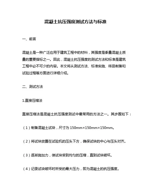
二、测试方法1.直接压缩法直接压缩法是混凝土抗压强度测试中最常用的方法之一。
其步骤如下:(1)制备混凝土试块,尺寸为150mm×150mm×150mm。
(2)将试块放置在试验机的压头下方,确保试块的中心与压头对齐。
(3)逐渐施加力,使试块受到均匀的压缩,直到试块破坏。
(4)记录试块破坏时所受的最大压力,即为混凝土的抗压强度。
2.间接拉伸法间接拉伸法也是一种常用的混凝土抗压强度测试方法。
其步骤如下:(1)制备混凝土试块,尺寸为150mm×150mm×150mm。
(2)将试块放置在试验机的两个压头之间,使试块受到拉伸力。
(3)逐渐施加力,使试块受到均匀的拉伸力,直到试块破坏。
(4)记录试块破坏时所受的最大拉伸力,根据试块的尺寸计算出混凝土的抗压强度。
三、标准实施混凝土抗压强度测试需要遵循一系列标准,以确保测试结果的准确性和可靠性。
以下是一些常用的标准:1.GB/T 50081-2002 混凝土抗压强度试验方法标准2.ASTM C39/C39M-19a Standard Test Method for Compressive Strength of Cylindrical Concrete Specimens3.ISO 1920-3:2001 Concrete Test Specimens. Part 3: Making and Curing Specimens for Strength Tests这些标准规定了试验的具体步骤、样品制备和试验条件等,测试人员需要严格遵守这些标准的要求,以确保测试结果的准确性。
四、样品制备混凝土试块的制备需要注意以下几点:1.混凝土试块的尺寸应符合标准规定,通常为150mm×150mm×150mm或100mm×100mm×100mm。
混凝土轴心抗压强度试验标准试件尺寸一、引言混凝土轴心抗压强度试验是判断混凝土强度的重要指标。
试验标准试件尺寸的选择对试验结果的准确性和可比性具有重要影响。
本文将详细介绍混凝土轴心抗压强度试验标准试件尺寸的相关标准和要求。
二、试验标准混凝土轴心抗压强度试验标准主要包括GB/T 50081-2002《混凝土抗拉强度和抗压强度试验方法规程》、JGJ/T 23-2011《混凝土抗压强度试验方法标准》、ASTM C39/C39M-19《Standard Test Method for Compressive Strength of Cylindrical Concrete Specimens》、EN 12390-3:2019《Testing hardened concrete - Part 3: Compressive strength of test specimens》等。
三、试件尺寸根据上述标准,混凝土轴心抗压强度试验标准试件尺寸一般为直径为150mm,高度为300mm的圆柱体。
但不同标准对试件尺寸有一定的差异,具体如下:1. GB/T 50081-2002GB/T 50081-2002规定,混凝土轴心抗压强度试验标准试件尺寸为直径为150mm,高度为300mm的圆柱体。
但也可以根据需要选择其他尺寸的试件,如直径为100mm,高度为200mm的圆柱体。
2. JGJ/T 23-2011JGJ/T 23-2011规定,混凝土轴心抗压强度试验标准试件尺寸为直径为150mm,高度为300mm的圆柱体。
其他尺寸的试件可以根据需要选择,但直径不应小于100mm,高度不应小于200mm。
3. ASTM C39/C39M-19ASTM C39/C39M-19规定,混凝土轴心抗压强度试验标准试件尺寸为直径为150mm,高度为300mm的圆柱体。
其他尺寸的试件可以根据需要选择,但直径不应小于100mm,高度不应小于200mm。

混凝土制品的标准硬度混凝土制品的标准硬度混凝土制品是一种常见的建筑材料,用于制造各种建筑构件,如地基、墙体、楼板等。
混凝土制品的质量直接关系到建筑物的安全性和耐久性,因此,混凝土制品的硬度是一个重要的性能指标。
标准硬度的概念标准硬度是指一种材料在特定条件下的硬度指标,通常使用一定的试验方法进行测试,并将测试结果与相应的标准进行比较,以确定材料的硬度是否符合标准。
标准硬度对于混凝土制品来说,是一个重要的质量控制指标,可以用于检测混凝土制品的硬度是否符合要求。
混凝土制品的标准硬度测试方法混凝土制品的标准硬度测试通常使用压力试验法进行。
该测试方法需要使用一台万能试验机和一组压力板,压力板的尺寸和形状应符合相应的标准。
测试时,将混凝土制品放在压力板上,然后向上施加一定的压力,直到混凝土制品发生破坏。
测试过程中需要记录下压力和位移的变化,并计算出混凝土制品的标准硬度。
混凝土制品的标准硬度标准混凝土制品的标准硬度标准通常由国际标准组织或各国的建筑标准化机构制定。
以下是一些常用的混凝土制品标准硬度标准:1. ASTM C39/C39M-20a Standard Test Method for Compressive Strength of Cylindrical Concrete Specimens该标准规定了用于测试混凝土圆柱体的压力试验法。
标准规定了测试所需的设备、试样制备方法、测试程序和结果计算方法。
2. BS EN 12390-3:2019 Testing hardened concrete - Part 3: Compressive strength of test specimens该标准规定了用于测试混凝土试样(包括立方体、圆柱体和长方体)的压力试验法。
标准规定了测试所需的设备、试样制备方法、测试程序和结果计算方法。
3. GB/T 50081-2002 混凝土强度检验方法标准该标准规定了用于测试混凝土试样(包括立方体、圆柱体和长方体)的压力试验法。

混凝土梁的压缩强度标准一、前言混凝土梁是建筑结构中常用的构件之一,其承受的荷载主要为弯曲荷载和压力荷载。
因此,混凝土梁的压缩强度是评价其性能的重要指标之一。
本文旨在详细介绍混凝土梁的压缩强度标准,包括国内外相关标准、标准中所涉及的测试方法以及标准的适用范围等内容,以期为建筑工程及相关领域的人员提供参考。
二、国内相关标准1. GB 50010-2010《混凝土结构设计规范》GB 50010-2010是我国混凝土结构设计的基础性标准,其中规定了混凝土梁的设计强度和构造要求等内容。
在该标准中,混凝土梁的压缩强度指标为f_c,其计算公式为:f_c = 0.45f_cj其中,f_cj为混凝土立方体抗压强度设计值。
2. GB/T 50081-2002《建筑结构试验方法标准》GB/T 50081-2002是我国建筑结构试验方法的基础性标准,其中规定了混凝土梁的试验方法。
在该标准中,混凝土梁的压缩强度试验采用静载试验方法,试验结果为混凝土梁的极限荷载,通过计算得出混凝土梁的极限压应力。
3. JGJ/T 151-2008《混凝土结构工程施工质量验收规范》JGJ/T 151-2008是我国混凝土结构工程施工质量验收的标准,其中规定了混凝土梁的验收标准。
在该标准中,混凝土梁的压缩强度指标为f_cj,其验收标准为:当f_cj≥f_cj0.85时,混凝土梁合格。
三、国际相关标准1. ACI 318-14《Building Code Requirements for Structural Concrete and Commentary》ACI 318-14是美国混凝土结构设计的基础性标准,其中规定了混凝土梁的设计强度和构造要求等内容。
在该标准中,混凝土梁的压缩强度指标为f'_c,其计算公式为:f'_c = 0.85f_c其中,f_c为混凝土立方体抗压强度标准值。
2. ASTM C39/C39M-18《Standard Test Method for Compressive Strength of Cylindrical Concrete Specimens》ASTM C39/C39M-18是美国混凝土梁的压缩强度试验方法标准。
混凝土强度检验的国际标准对比一、引言混凝土是广泛应用于建筑和基础设施工程中的一种常用材料。
为了确保混凝土工程的质量和安全性,强度检验是必不可少的一环。
本文旨在对比不同国际标准对混凝土强度检验的要求和方法,以期促进标准化和互通有无。
二、美国标准在美国,混凝土的强度检验主要依据ASTM C39标准,即“混凝土立方体抗压强度试验”。
根据该标准,混凝土样品采用标准尺寸,经过一定养护时间后,在试验机上进行加载,以确定其抗压强度。
ASTM C39标准详细规定了试验机的要求、加载速率、取样方法等。
三、欧洲标准在欧洲,混凝土强度检验的相关标准主要有EN 12390-3和EN 206-1。
EN 12390-3标准规定了混凝土立方体和圆柱体抗压强度试验的具体要求,特别强调试验前的养护条件和试样的尺寸。
而EN 206-1则是欧洲对混凝土的整体性能要求的集成标准,对强度检验的方法也有所涉及。
四、中国标准中国国内对混凝土强度检验的标准则主要包括GB/T 50081和GB/T 50082标准。
GB/T 50081标准规定了混凝土抗压强度试验的方法和要求,包括试样制备、试验机的使用、加载速率等方面。
GB/T 50082标准则进一步细化了混凝土制样和试验工作的具体指导,以确保检验结果的准确性和可靠性。
五、对比分析从以上对不同国际标准的介绍可见,混凝土强度检验的方法和要求在各个标准中有所差异,但总体上保持了一定的统一性。
主要差异体现在对试样尺寸、试样养护条件、试验机使用等方面的规定上。
例如,美国标准更注重试验机的要求和加载速率的确定,而欧洲标准则更强调试验前的养护条件,以及总体性能要求的细化。
中国标准则在制样和试验工作方面有更为详细的规定,以确保检验结果的准确性。
六、标准化与互通混凝土强度检验的国际标准对比表明,各个标准在方法和要求上的一致性尚可,但仍存在一些差异。
为了推动全球混凝土行业的标准化和互通有无,建议各国之间加强交流与合作,共同制定更加统一的标准。

混凝土抗压强度的测试方法一、背景混凝土是建筑工程中常用的材料之一,主要用于建筑结构的承重和保温隔热。
混凝土的质量直接影响建筑的安全性和耐久性,因此需要对混凝土的性能进行测试和评估。
其中,混凝土抗压强度是评估混凝土质量的重要指标之一。
本文将就混凝土抗压强度的测试方法进行详细的介绍。
二、相关标准混凝土抗压强度的测试方法需要遵循相关标准。
以下是常用的几种标准:1. GB/T 50081-2002《混凝土结构设计规范》2. GB/T 50107-2010《建筑混凝土强度检验规程》3. JGJ/T 70-2009《建筑工程混凝土试验规程》4. ASTM C39/C39M-18a《Standard Test Method for Compressive Strength of Cylindrical Concrete Specimens》三、测试设备混凝土抗压强度的测试需要使用特定的设备,以下是常用的几种设备:1. 混凝土试块模具2. 手动或电动压力试验机3. 电子天平4. 直尺、卷尺等量具四、试块制备混凝土试块是进行抗压强度测试的标准样品。
试块制备需要遵循以下步骤:1. 混凝土样品的取样:从混凝土搅拌站或建筑工地取样,每个样品至少应取三个试块。
2. 混凝土试块的制备:将混凝土样品倒入试块模具中,每层压实一次,直至模具填满混凝土。
最后用刮板刮平试块表面,然后标记试块编号和制备日期。
3. 混凝土试块的养护:在试块制备后,需要对试块进行养护。
首先在模具中将试块进行振实,然后在试块表面喷水,覆盖塑料薄膜,进行养护。
养护时间一般为28天。
五、试验步骤进行混凝土抗压强度测试的步骤如下:1. 取出养护好的混凝土试块,将试块编号记录在试验记录表上。
2. 用直尺或卷尺测量试块的直径和高度,并记录在试验记录表上。
3. 将试块放在试验机的压板上,调整试验机的压头位置,使其与试块平行。
4. 在试验机上设置加载速率和加载方式,开始加载试块,记录试块在不同加载阶段的压力和位移值。

混凝土试验方法的新标准解读一、前言混凝土是建筑工程中使用最多的建筑材料之一,其强度、耐久性及其他性能对于建筑物的质量和安全至关重要。
为了保证混凝土的质量,需要进行各种试验,并按照相应的标准进行评估。
本文将介绍混凝土试验方法的新标准解读。
二、混凝土试验方法的新标准1. GB/T 50080-2016《混凝土工程施工质量验收规范》该标准是中国建筑标准化协会发布的混凝土施工验收规范。
其中包含了混凝土的常规试验方法、特殊试验方法、试验结果的计算和评定等内容。
该标准的主要内容包括:(1)混凝土抗压强度试验:按照标准规定的方法进行试验,包括试样制备、试样养护、试样加荷、试样破坏等。
(2)混凝土抗拉强度试验:按照标准规定的方法进行试验,包括试样制备、试样养护、试样加荷、试样破坏等。
(3)混凝土抗折强度试验:按照标准规定的方法进行试验,包括试样制备、试样养护、试样加荷、试样破坏等。
(4)混凝土孔隙率试验:按照标准规定的方法进行试验,包括试样制备、试样养护、试样称重、试样浸水、试样干燥等。
2. ASTM C39/C39M-20《Standard Test Method for Compressive Strength of Cylindrical Concrete Specimens》该标准是美国材料与试验协会(ASTM)发布的混凝土抗压强度试验标准。
该标准规定了混凝土试样的制备、试样养护、试样加荷、试样破坏等步骤,并规定了试验结果的计算和评定方法。
该标准的主要内容包括:(1)试样制备:按照标准规定的方法制备试样,包括试样尺寸、试样表面平整度、试样养护等。
(2)试样养护:按照标准规定的方法进行试样养护,包括试样养护时间、试样养护条件等。
(3)试样加荷:按照标准规定的方法进行试样加荷,包括试样加荷速率、试样加荷方式等。
(4)试样破坏:按照标准规定的方法进行试样破坏,包括试样破坏形式、试样破坏位置等。
3. EN 12390-3:2019《Testing hardened concrete - Part 3: Compressive strength of test specimens》该标准是欧洲标准化组织(CEN)发布的混凝土抗压强度试验标准。
混凝土早期强度测试方法及标准一、前言混凝土早期强度是指混凝土在浇筑后的短时间内能够承受的荷载。
对于一些建筑项目,必须在短时间内达到一定的强度,以满足使用要求。
因此,混凝土早期强度测试方法及标准对于建筑工程来说非常重要。
本文将详细介绍混凝土早期强度测试方法及标准。
二、混凝土早期强度测试方法1. 压实度法压实度法是一种常用的测试混凝土早期强度的方法。
该方法通过对混凝土的压实程度进行测量,来判断混凝土的早期强度。
具体测试步骤如下:(1)在混凝土浇筑完成后的2小时内,用锤子敲击混凝土表面,观察混凝土的反弹情况。
(2)用压实度仪在敲击的位置上进行测试,记录压实度值。
(3)根据压实度值来判断混凝土早期强度的等级。
2. 塑性模量法塑性模量法是另一种测试混凝土早期强度的方法。
该方法通过测量混凝土的变形情况,来判断混凝土的早期强度。
具体测试步骤如下:(1)在混凝土浇筑完成后的4小时内,用测定仪器测量混凝土的变形。
(2)根据测量结果来计算混凝土的塑性模量。
(3)根据塑性模量值来判断混凝土早期强度的等级。
3. 压痕法压痕法是一种比较简单的测试混凝土早期强度的方法。
该方法通过在混凝土表面压入一定深度的痕迹,来判断混凝土的早期强度。
具体测试步骤如下:(1)在混凝土浇筑完成后的6小时内,用压痕仪在混凝土表面进行测试。
(2)根据测试结果来计算混凝土的硬度值。
(3)根据硬度值来判断混凝土早期强度的等级。
三、混凝土早期强度测试标准1. GB/T 50080-2016 混凝土强度检验标准GB/T 50080-2016是我国混凝土强度检验标准,其中包括了对混凝土早期强度测试的要求。
该标准规定了混凝土早期强度测试的方法和标准,以及测试时的注意事项和要求。
2. ASTM C39/C39M-18 Standard Test Method for Compressive Strength of Cylindrical Concrete SpecimensASTM C39/C39M-18是美国材料和试验协会发布的混凝土压缩强度测试标准,其中包括了对混凝土早期强度测试的要求。
混凝土试验块尺寸规定一、前言混凝土试验块是评价混凝土强度的重要工具之一。
试验块的尺寸规定对于混凝土强度测试结果的准确性和可靠性至关重要。
因此,本文将详细介绍混凝土试验块尺寸规定的相关内容。
二、试验块尺寸的定义混凝土试验块是在混凝土浇筑后,在规定的时间内制成的用于测定混凝土强度的标准化样品。
试验块尺寸包括长度、宽度和厚度三个方面的尺寸。
三、试验块尺寸的规定试验块尺寸的规定通常由国家或地区的标准机构制定,以下是一些常见的混凝土试验块尺寸规定。
1. 中国标准根据中国国家标准《混凝土强度检验方法》(GB/T 50080-2016),混凝土试验块的尺寸规定如下:(1) 尺寸:150mm×150mm×150mm(2) 允许偏差:尺寸偏差不得大于±1.5mm(3) 表面平整度:每个表面的最大偏差不得大于0.3mm(4) 齐平度:试验块平面间的最大偏差不得大于0.5mm2. 美国标准根据美国标准《混凝土和混凝土制品的试验方法》(ASTMC39/C39M-19),混凝土试验块的尺寸规定如下:(1) 尺寸:150mm×150mm×150mm或100mm×100mm×100mm(2) 允许偏差:尺寸偏差不得大于±1.5mm(3) 表面平整度:每个表面的最大偏差不得大于0.3mm(4) 齐平度:试验块平面间的最大偏差不得大于0.5mm3. 欧洲标准根据欧洲标准《混凝土的试验方法》(EN 12390-1:2019),混凝土试验块的尺寸规定如下:(1) 尺寸:150mm×150mm×150mm或100mm×100mm×100mm(2) 允许偏差:尺寸偏差不得大于±1.5mm(3) 表面平整度:每个表面的最大偏差不得大于0.3mm(4) 齐平度:试验块平面间的最大偏差不得大于0.5mm四、试验块尺寸的影响因素试验块尺寸对混凝土强度测试结果有重要影响,以下是试验块尺寸影响的一些主要因素。
混凝土受压性能检测标准一、引言混凝土是建筑工程中最常用的建筑材料之一,其受压性能检测是保证建筑质量和安全的重要环节。
目前,国内外已经形成了一系列的混凝土受压性能检测标准。
本文将重点介绍国内外常用的混凝土受压性能检测标准。
二、国内常用的混凝土受压性能检测标准1. GB/T 50081-2002《混凝土力学性能试验方法标准》该标准是国家强制性标准,适用于混凝土强度、变形、断裂韧性等力学性能的试验方法。
其中,混凝土强度试验主要包括标准立方体试件、标准圆柱试件、直接拉伸试验和间接拉伸试验四种方法。
2. JGJ/T 70-2009《混凝土工程质量检验与评定标准》该标准是国家行业标准,适用于混凝土的施工、检验和评定。
其中,混凝土强度试验包括标准立方体试件和标准圆柱试件两种方法。
该标准还规定了混凝土的质量控制要求和检验方法。
3. JGJ/T 152-2008《混凝土试验规程》该标准是国家行业标准,适用于混凝土的试验方法和规程。
其中,混凝土强度试验主要包括标准立方体试件、标准圆柱试件和间接拉伸试验三种方法。
该标准还规定了混凝土的试验前准备、试验设备和操作要求等内容。
4. DBJ08-216-1999《建筑结构混凝土试验标准》该标准是国家行业标准,适用于建筑结构混凝土的试验方法和规程。
其中,混凝土强度试验主要包括标准立方体试件、标准圆柱试件和间接拉伸试验三种方法。
该标准还规定了混凝土的试验前准备、试验设备和操作要求等内容。
三、国际常用的混凝土受压性能检测标准1. ASTM C39/C39M-18《Standard Test Method for Compressive Strength of Cylindrical Concrete Specimens》该标准是美国材料与试验协会(ASTM)发布的标准,适用于混凝土圆柱试件的强度试验。
该标准规定了试验前准备、试验设备、试验过程和试验结果的计算方法等内容。
2. BS EN 12390-3:2019《Testing hardened concrete - Part 3: Compressive strength of test specimens》该标准是欧洲标准化委员会发布的标准,适用于混凝土试件的强度试验。
混凝土强度与耐久性测试标准一、前言混凝土是一种广泛应用的建筑材料,具有良好的强度和耐久性,但其质量的稳定性和长期使用后的性能变化是人们一直关注的问题。
因此,建立一套完善的混凝土强度和耐久性测试标准,对于确保混凝土工程的质量和安全具有重要意义。
本文将从混凝土强度和耐久性两个方面,详细介绍当前国内外常用的测试标准和方法,希望能够为相关行业提供参考和指导。
二、混凝土强度测试标准混凝土强度是评价混凝土质量的重要指标之一,其测试标准的制定需要考虑多方面的因素。
以下是国内外常用的几种混凝土强度测试标准。
1.中国国家标准GB/T 50081-2002《混凝土抗压强度试验方法标准》该标准规定了混凝土抗压强度试验的一般要求、试验设备、试验方法、试验过程、数据处理和试验报告等内容。
该标准适用于混凝土抗压强度的试验和测定。
2.美国标准ASTM C39/C39M-18a《Standard Test Method for Compressive Strength of Cylindrical Concrete Specimens》该标准规定了在室温下测定混凝土圆柱体抗压强度的试验方法。
该标准适用于混凝土强度的试验和测定。
3.欧洲标准EN 12390-3:2019《Testing hardened concrete - Part 3: Compressive strength of test specimens》该标准规定了在实验室中测定混凝土试件抗压强度的试验方法。
该标准适用于混凝土强度的试验和测定。
4.日本工业标准JIS A 1108-1:2016《Testing methods for physical properties of hardened concrete - Part 1: Compressive strength of cylindrical specimens》该标准规定了在实验室中测定混凝土圆柱体抗压强度的试验方法。
混凝土抗压试验参考文献混凝土抗压试验是评估混凝土在承受外部压力时的强度和稳定性的关键方法。
通过进行抗压试验,我们能够了解混凝土的力学性能,为工程设计和施工提供可靠的依据。
以下是一些相关的参考文献。
1. ACI 318-14 "Building Code Requirements for Structural Concrete":这是美国混凝土协会(ACI)发布的混凝土结构设计规范,其中包含了混凝土抗压试验的要求和方法。
2. ASTM C39/C39M-20 "Standard Test Method for Compressive Strength of Cylindrical Concrete Specimens":这是美国材料和试验协会(ASTM)发布的混凝土抗压试验的标准方法,通过对圆柱形混凝土试样进行压力加载,评估混凝土的抗压强度。
3. ASTM C78/C78M-18 "Standard Test Method for Flexural Strength of Concrete (Using Simple Beam with Third-Point Loading)":这是ASTM发布的混凝土抗弯强度测试方法,通过对简支梁进行三点弯曲加载,评估混凝土的抗弯强度。
4. BS EN 12390-3:2019 "Testing hardened concrete - Part 3: Compressive strength of test specimens":这是欧洲标准化组织(CEN)发布的混凝土抗压试验的标准方法,其中包括对试样进行压力加载,评估混凝土的抗压强度。
5. BS EN 12390-5:2019 "Testing hardened concrete - Part 5: Flexural strength of test specimens":这是CEN发布的混凝土抗弯强度测试方法,通过对试样进行弯曲加载,评估混凝土的抗弯强度。
混凝土压缩强度检测标准一、前言混凝土是建筑中常见的材料之一,它具有强度高、耐久性好、施工方便等优点,因此在建筑中得到广泛应用。
然而,混凝土强度的检测对于保证建筑质量至关重要。
本文将就混凝土压缩强度检测标准进行详细说明。
二、混凝土压缩强度检测标准概述混凝土压缩强度检测旨在评估混凝土的质量,通过测定混凝土的抗压强度来判断其是否符合设计要求。
通常情况下,混凝土的压缩强度检测是在混凝土的成型后进行的。
在混凝土的成型过程中,需要保证混凝土的配合比、水灰比等参数符合设计要求,以确保混凝土的质量。
三、混凝土压缩强度检测方法1. 实验设备混凝土压缩强度检测需要使用压力机,压力机的规格、型号应符合相关标准要求。
同时,还需要使用混凝土试块模具、试块抹光器、试块灰尘刷等实验设备。
2. 试块制备试块制备是混凝土压缩强度检测的重要步骤。
试块制备需要按照相关标准进行,试块模具的尺寸应符合标准要求。
在制备试块的过程中,需要注意保证混凝土的配合比、水灰比等参数符合设计要求。
3. 试块养护试块的养护是混凝土压缩强度检测的另一个重要步骤。
试块养护需要在试块成型后尽快进行,养护的时间应符合相关标准要求。
在试块养护的过程中,需要注意保持试块表面湿润,避免试块表面出现龟裂等情况。
4. 试块检测试块检测是混凝土压缩强度检测的最后一步。
试块检测需要使用压力机进行,检测时需要注意压力机的工作稳定性、试块的位置等因素。
检测时需要记录试块的破坏强度,并进行数据分析。
四、混凝土压缩强度检测标准混凝土压缩强度检测的标准有多个,以下介绍几个常用的标准:1. GB/T 50081-2002《混凝土试验方法标准规程》2. JGJ/T 70-2009《建筑混凝土强度检测与评定规范》3. ASTM C39/C39M-18a《Standard Test Method for Compressive Strength of Cylindrical Concrete Specimens》4. ACI 318-19《Building Code Requirements for Structural Concrete and Commentary》五、混凝土压缩强度检测结果分析混凝土压缩强度检测的结果需要进行数据分析,通常情况下需要计算出试块的平均强度值以及标准偏差等数据。
N OTE1—The testing laboratory performing this test method should be evaluated in accordance with Practice C1077.5.Apparatus5.1Testing Machine—The testing machine shall be of a type having sufficient capacity and capable of providing the rates of loading prescribed in7.5.5.1.1Verification of calibration of the testing machines in accordance with Practices E4is required under the following conditions:5.1.1.1After an elapsed interval since the previous verifi-cation of18months maximum,but preferably after an interval of12months,5.1.1.2On original installation or relocation of the machine, 5.1.1.3Immediately after making repairs or adjustments that affect the operation of the force applying system of the machine or the values displayed on the load indicating system, except for zero adjustments that compensate for the mass of bearing blocks,or specimen,or both,or5.1.1.4Whenever there is reason to doubt the accuracy of the results,without regard to the time interval since the last verification.5.1.2Design—The design of the machine must include the following features:5.1.2.1The machine must be power operated and must apply the load continuously rather than intermittently,and without shock.If it has only one loading rate(meeting the requirements of7.5),it must be provided with a supplemental means for loading at a rate suitable for verification.This supplemental means of loading may be power or hand oper-ated.N OTE2—High-strength concrete cylinders rupture more intensely than normal strength cylinders.As a safety precaution,it is recommended that the testing machines should be equipped with protective fragment guards.5.1.2.2The space provided for test specimens shall be large enough to accommodate,in a readable position,an elastic calibration device which is of sufficient capacity to cover the potential loading range of the testing machine and which complies with the requirements of Practice E74.N OTE3—The types of elastic calibration devices most generally avail-able and most commonly used for this purpose are the circular proving ring or load cell.5.1.3Accuracy—The accuracy of the testing machine shall be in accordance with the following provisions:5.1.3.1The percentage of error for the loads within the proposed range of use of the testing machine shall not exceed 61.0%of the indicated load.5.1.3.2The accuracy of the testing machine shall be verified by applyingfive test loads in four approximately equal increments in ascending order.The difference between any two successive test loads shall not exceed one third of the differ-ence between the maximum and minimum test loads.5.1.3.3The test load as indicated by the testing machine and the applied load computed from the readings of the verification device shall be recorded at each test point.Calculate the error, E,and the percentage of error,E p,for each point from these data as follows:E5A2B(1)E p5100~A2B!/Bwhere:A5load,lbf[kN]indicated by the machine being verified, andB5applied load,lbf[kN]as determined by the calibrating device.5.1.3.4The report on the verification of a testing machine shall state within what loading range it was found to conform to specification requirements rather than reporting a blanket acceptance or rejection.In no case shall the loading range be stated as including loads below the value which is100times the smallest change of load estimable on the load-indicating mechanism of the testing machine or loads within that portion of the range below10%of the maximum range capacity. 5.1.3.5In no case shall the loading range be stated as including loads outside the range of loads applied during the verification test.5.1.3.6The indicated load of a testing machine shall not be corrected either by calculation or by the use of a calibration diagram to obtain values within the required permissible variation.5.2The testing machine shall be equipped with two steel bearing blocks with hardened faces(Note4),one of which is a spherically seated block that will bear on the upper surface of the specimen,and the other a solid block on which the specimen shall rest.Bearing faces of the blocks shall have a minimum dimension at least3%greater than the diameter of the specimen to be tested.Except for the concentric circles described below,the bearing faces shall not depart from a plane by more than0.001in.[0.02mm]in any6in.[150mm]of blocks6in.[150mm]in diameter or larger,or by more than 0.001in.[0.02mm]in the diameter of any smaller block;and new blocks shall be manufactured within one half of this tolerance.When the diameter of the bearing face of the spherically seated block exceeds the diameter of the specimen by more than0.5in.[13mm],concentric circles not more than 0.03in.[0.8mm]deep and not more than0.04in.[1mm]wide shall be inscribed to facilitate proper centering.N OTE4—It is desirable that the bearing faces of blocks used for compression testing of concrete have a Rockwell hardness of not less than 55HRC.5.2.1Bottom bearing blocks shall conform to the following requirements:5.2.1.1The bottom bearing block is specified for the pur-pose of providing a readily machinable surface for mainte-nance of the specified surface conditions(Note5).The top and bottom surfaces shall be parallel to each other.If the testing machine is so designed that the platen itself is readily main-tained in the specified surface condition,a bottom block is not required.Its least horizontal dimension shall be at least3% greater than the diameter of the specimen to be tested. Concentric circles as described in5.2are optional on the bottom block.N OTE5—The block may be fastened to the platen of the testing machine.5.2.1.2Final centering must be made with reference to the upper spherical block.When the lower bearing block is usedtoassist in centering the specimen,the center of the concentricrings,when provided,or the center of the block itself must bedirectly below the center of the spherical head.Provision shallbe made on the platen of the machine to assure such a position.5.2.1.3The bottom bearing block shall be at least 1in.[25mm]thick when new,and at least 0.9in.[22.5mm]thick afterany resurfacing operations.5.2.2The spherically seated bearing block shall conform tothe following requirements:5.2.2.1The maximum diameter of the bearing face of thesuspended spherically seated block shall not exceed the valuesgiven below:Diameter of Maximum DiameterTest Specimens,of Bearing Face,in.[mm]in.[mm]2[50]4[105]3[75]5[130]4[100] 6.5[165]6[150]10[255]8[200]11[280]N OTE 6—Square bearing faces are permissible,provided the diameterof the largest possible inscribed circle does not exceed the above diameter.5.2.2.2The center of the sphere shall coincide with thesurface of the bearing face within a tolerance of 65%of theradius of the sphere.The diameter of the sphere shall be at least75%of the diameter of the specimen to be tested.5.2.2.3The ball and the socket must be so designed by themanufacturer that the steel in the contact area does notpermanently deform under repeated use,with loads up to12000psi [85MPa]on the test specimen.N OTE 7—The preferred contact area is in the form of a ring (describedas preferred“bearing”area)as shown on Fig.1.5.2.2.4The curved surfaces of the socket and of the spheri-cal portion shall be kept clean and shall be lubricated with apetroleum-type oil such as conventional motor oil,not with apressure type grease.After contacting the specimen and appli-cation of small initial load,further tilting of the sphericallyseated block is not intended and is undesirable.5.2.2.5If the radius of the sphere is smaller than the radius of the largest specimen to be tested,the portion of the bearing face extending beyond the sphere shall have a thickness not less than the difference between the radius of the sphere and radius of the specimen.The least dimension of the bearing face shall be at least as great as the diameter of the sphere (see Fig.1).5.2.2.6The movable portion of the bearing block shall be held closely in the spherical seat,but the design shall be such that the bearing face can be rotated freely and tilted at least 4°in any direction.5.3Load Indication :5.3.1If the load of a compression machine used in concrete testing is registered on a dial,the dial shall be provided with a graduated scale that is readable to at least the nearest 0.1%of the full scale load (Note 8).The dial shall be readable within 1%of the indicated load at any given load level within the loading range.In no case shall the loading range of a dial be considered to include loads below the value that is 100times the smallest change of load that can be read on the scale.The scale shall be provided with a graduation line equal to zero and so numbered.The dial pointer shall be of sufficient length to reach the graduation marks;the width of the end of the pointer shall not exceed the clear distance between the smallest graduations.Each dial shall be equipped with a zero adjust-ment located outside the dialcase and easily accessible from the front of the machine while observing the zero mark and dial pointer.Each dial shall be equipped with a suitable device that at all times until reset,will indicate to within 1%accuracy the maximum load applied to the specimen.N OTE 8—Readability is considered to be 0.02in.[0.5mm]along the arc described by the end of the pointer.Also,one half of a scale interval is readable with reasonable certainty when the spacing on the load indicating mechanism is between 0.04in.[1mm]and 0.06in.[2mm].When the spacing is between 0.06and 0.12in.[2and 3mm],one third of a scale interval is readable with reasonable certainty.When the spacing is 0.12in.[3mm]or more,one fourth of a scale interval is readable with reasonable certainty.5.3.2If the testing machine load is indicated in digital form,the numerical display must be large enough to be easily read.The numerical increment must be equal to or less than 0.10%of the full scale load of a given loading range.In no case shall the verified loading range include loads less than the minimum numerical increment multiplied by 100.The accuracy of the indicated load must be within 1.0%for any value displayed within the verified loading range.Provision must be made for adjusting to indicate true zero at zero load.There shall be provided a maximum load indicator that at all times until reset will indicate within 1%system accuracy the maximum load applied to the specimen.6.Specimens 6.1Specimens shall not be tested if any individual diameter of a cylinder differs from any other diameter of the same cylinder by more than 2%.N OTE 9—This may occur when single use molds are damaged or deformed during shipment,when flexible single use molds are deformed during molding or when a core drill deflects or shifts during drilling.6.2Neither end of compressive test specimens whentestedN OTE 1—Provision shall be made for holding the ball in the socket andfor holding the entire unit in the testing machine.FIG.1Schematic Sketch of a Typical Spherical BearingBlockshall depart from perpendicularity to the axis by more than0.5°(approximately equivalent to0.12in12in.[3in300mm]).The ends of compression test specimens that are not plane within 0.002in.[0.050mm]shall be sawed or ground to meet that tolerance,or capped in accordance with either Practice C617 or Practice C1231.The diameter used for calculating the cross-sectional area of the test specimen shall be determined to the nearest0.01in.[0.25mm]by averaging two diameters measured at right angles to each other at about midheight of the specimen.6.3The number of individual cylinders measured for deter-mination of average diameter may be reduced to one for each ten specimens or three specimens per day,whichever is greater, if all cylinders are known to have been made from a single lot of reusable or single-use molds which consistently produce specimens with average diameters within a range of0.02in.[0.5mm].When the average diameters do not fall within the range of0.02in.[0.5mm]or when the cylinders are not made from a single lot of molds,each cylinder tested must be measured and the value used in calculation of the unit compressive strength of that specimen.When the diameters are measured at the reduced frequency,the cross-sectional areas of all cylinders tested on that day shall be computed from the average of the diameters of the three or more cylinders representing the group tested that day.6.4The length shall be measured to the nearest0.05D when the length to diameter ratio is less than1.8,or more than2.2, or when the volume of the cylinder is determined from measured dimensions.7.Procedure7.1Compression tests of moist-cured specimens shall be made as soon as practicable after removal from moist storage.7.2Test specimens shall be kept moist by any convenient method during the period between removal from moist storage and testing.They shall be tested in the moist condition.7.3All test specimens for a given test age shall be broken within the permissible time tolerances prescribed as follows: Test Age Permissible Tolerance24h60.5h or2.1%3days2h or2.8%7days6h or3.6%28days20h or3.0%90days2days2.2%7.4Placing the Specimen—Place the plain(lower)bearing block,with its hardened face up,on the table or platen of the testing machine directly under the spherically seated(upper) bearing block.Wipe clean the bearing faces of the upper and lower bearing blocks and of the test specimen and place the test specimen on the lower bearing block.Carefully align the axis of the specimen with the center of thrust of the spherically seated block.7.4.1Zero Verification and Block Seating—Prior to testing the specimen,verify that the load indicator is set to zero.In cases where the indicator is not properly set to zero,adjust the indicator(Note10).As the spherically seated block is brought to bear on the specimen,rotate its movable portion gently by hand so that uniform seating is obtained.N OTE10—The technique used to verify and adjust load indicator to zero will vary depending on the machine manufacturer.Consult your owner’s manual or compression machine calibrator for the proper tech-nique.7.5Rate of Loading—Apply the load continuously and without shock.7.5.1For testing machines of the screw type,the moving head shall travel at a rate of approximately0.05in.[1mm]/min when the machine is running idle.For hydraulically operated machines,the load shall be applied at a rate of movement (platen to crosshead measurement)corresponding to a loading rate on the specimen within the range of20to50psi/s[0.15to 0.35MPa/s].The designated rate of movement shall be maintained at least during the latter half of the anticipated loading phase of the testing cycle.7.5.2During the application of thefirst half of the antici-pated loading phase a higher rate of loading shall be permitted.7.5.3Make no adjustment in the rate of movement of the platen at any time while a specimen is yielding rapidly immediately before failure.7.6Apply the load until the specimen fails,and record the maximum load carried by the specimen during the test.Note the type of failure and the appearance of the concrete.8.Calculation8.1Calculate the compressive strength of the specimen by dividing the maximum load carried by the specimen during the test by the average cross-sectional area determined as de-scribed in Section6and express the result to the nearest10psi [0.1MPa].8.2If the specimen length to diameter ratio is less than1.8, correct the result obtained in8.1by multiplying by the appropriate correction factor shown in the following table: L/D: 1.75 1.50 1.25 1.00Factor:0.980.960.930.87(Note11)N OTE11—These correction factors apply to lightweight concrete weighing between100and120lb/ft3[1600and1920kg/m3]and to normal weight concrete.They are applicable to concrete dry or soaked at the time of loading.Values not given in the table shall be determined by interpolation.The correction factors are applicable for nominal concrete strengths from2000to6000psi[15to45MPa].9.Report9.1Report the following information:9.1.1Identification number,9.1.2Diameter(and length,if outside the range of1.8D to 2.2D),in inches[millimetres],9.1.3Cross-sectional area,in square inches[square milli-metres],9.1.4Maximum load,in pounds-force[kilonewtons],9.1.5Compressive strength calculated to the nearest10psi [0.1MPa],9.1.6Type of fracture,if other than the usual cone(see Fig.2),9.1.7Defects in either specimen or caps,and,9.1.8Age of specimen.10.Precision and Bias10.1Precision—The single operator precision of tests of individual6by12in.[150by300mm]cylinders madefroma well-mixed sample of concrete is given for cylinders made ina laboratory environment and under normal field conditions(see 10.1.1).Coefficient ofAcceptable Range of A Variation A2results 3results Single operatorLaboratory conditions2.37% 6.6%7.8%Field conditions2.87%8.0%9.5%A These numbers represent respectively the (1s)and (d2s)limits as describedin Practice C 670.10.1.1The values given are applicable to 6by 12in.[150by300mm]cylinders with compressive strength between 2000and 8000psi [15to 55MPa].They are derived from CCRLconcrete reference sample data for laboratory conditions and a collection of 1265test reports from 225commercial testing laboratories in 1978.5N OTE 12—Subcommittee C09.03will re-examine recent CCRL Con-crete Reference Sample Program data and field test data to see if these values are representative of current practice and if they can be extended to cover a wider range of strengths and specimen sizes.10.2Bias —Since there is no accepted reference material,no statement on bias is being made.11.Keywords The American Society for Testing and Materials takes no position respecting the validity of any patent rights asserted in connection with any item mentioned in this ers of this standard are expressly advised that determination of the validity of any such patent rights,and the risk of infringement of such rights,are entirely their own responsibility.This standard is subject to revision at any time by the responsible technical committee and must be reviewed every five years and if not revised,either reapproved or withdrawn.Your comments are invited either for revision of this standard or for additional standards and should be addressed to ASTM Headquarters.Your comments will receive careful consideration at a meeting of the responsible technical committee,which you may attend.If you feel that your comments have not received a fair hearing you should make your views known to the ASTM Committee on Standards,100Barr Harbor Drive,West Conshohocken,PA 19428.This standard is copyrighted by ASTM,100Barr Harbor Drive,West Conshohocken,PA 19428-2959,United States.Individual reprints (single or multiple copies)of this standard may be obtained by contacting ASTM at the above address or at 610-832-9585(phone),610-832-9555(fax),or service@ (e-mail);or through the ASTM website ().5Research report RR:C09-1006is on file at ASTMHeadquarters.Cone(a)Cone and Split (b)Cone and Shear(c)Shear (d)Columnar (e)FIG.2Sketches of Types ofFracture。