DSP28335 I2C接口应用
- 格式:doc
- 大小:1.14 MB
- 文档页数:17
DSP I2C 应用说明1.示例程序中几种状态第一次看i2c_eeprom示例程序,对程序中的MsgStatus信息状态切换非常懵懂,为什么要有这几个状态?状态切换顺序如何安排?一大堆的状态,让人有些摸不着头脑。
先把程序中的头文件涉及的7种状态分析一下。
// I2C Message Commands for I2CMSG struct#define I2C_MSGSTAT_INACTIVE 0x0000 //未激活状态:一般成功发送数据或者//接受数据后可以设置信息状态为此状态,告诉用户可进行下一次的写数据或读数据。
#define I2C_MSGSTAT_SEND_WITHSTOP 0x0010 //发送带停止位数据:这是为写数据而设///的状态,写入地址和数据之后发个停止位告诉存储器数据写入完毕。
#define I2C_MSGSTAT_WRITE_BUSY 0x0011 //写数据忙状态:在将待写的数据放入//缓存后,就可以使能IIC传输数据了,然后把信息状态设为该状态,意在告诉用户:数据//已经在传送过程中。
当然是否传送完毕,还需要通过查询SCD位来判断。
#define I2C_MSGSTAT_SEND_NOSTOP 0x0020//发送无停止位数据:这个状态是为了读//取数据而设的,有查阅过AT24C1024EEPROM存储器使用手册的读者知道,在读数据之前//要发送数据的地址,发完地址不能产生停止位,这是存储器硬件设计决定的。
设为这个状//态意在告诉读者,可以发送要读取的数据的地址了。
#define I2C_MSGSTAT_SEND_NOSTOP_BUSY 0x0021//发送无停止位数据忙状态:这个状态是//为了读取数据而设的,似于I2C_MSGSTAT_WRITE_BUSY,说明地址数据已经在传送过程中。
//传送是否成功,还要看ARDY的状态。
#define I2C_MSGSTAT_RESTART 0x0022//重发开始位状态:这个状态也是为读取////数据而设。
D S P I2C应用说明1.示例程序中几种状态第一次看i2c_eeprom示例程序,对程序中的MsgStatus信息状态切换非常懵懂,为什么要有这几个状态?状态切换顺序如何安排?一大堆的状态,让人有些摸不着头脑。
先把程序中的头文件涉及的7种状态分析一下。
//I2CMessageCommandsforI2CMSGstruct#defineI2C_MSGSTAT_INACTIVE0x0000//未激活状态:一般成功发送数据或者//接受数据后可以设置信息状态为此状态,告诉用户可进行下一次的写数据或读数据。
#defineI2C_MSGSTAT_SEND_WITHSTOP0x0010//发送带停止位数据:这是为写数据而设///的状态,写入地址和数据之后发个停止位告诉存储器数据写入完毕。
#defineI2C_MSGSTAT_WRITE_BUSY0x0011//写数据忙状态:在将待写的数据放入//缓存后,就可以使能IIC传输数据了,然后把信息状态设为该状态,意在告诉用户:数据//已经在传送过程中。
当然是否传送完毕,还需要通过查询SCD位来判断。
#defineI2C_MSGSTAT_SEND_NOSTOP0x0020//发送无停止位数据:这个状态是为了读//取数据而设的,有查阅过AT24C1024EEPROM存储器使用手册的读者知道,在读数据之前//要发送数据的地址,发完地址不能产生停止位,这是存储器硬件设计决定的。
设为这个状//态意在告诉读者,可以发送要读取的数据的地址了。
#defineI2C_MSGSTAT_SEND_NOSTOP_BUSY0x0021//发送无停止位数据忙状态:这个状态是//为了读取数据而设的,似于I2C_MSGSTAT_WRITE_BUSY,说明地址数据已经在传送过程中。
//传送是否成功,还要看ARDY的状态。
#defineI2C_MSGSTAT_RESTART0x0022//重发开始位状态:这个状态也是为读取////数据而设。

1I2C寄存器1.1.1I2C模式寄存器——I2CMDR16位寄存器,包含了I2C模块的控制部分I2C作为主机时,RM、STT、STP位于总线发送/接收数据格式和总线状态关系表1.1.2I2C中断使能寄存器——I2CIER包括I2C中断的使能与屏蔽位;1.1.3I2C状态寄存器——I2CSTR包括中断标志状态和读状态信息;1.1.4I2C中断源寄存器——I2CSRC该寄存器主要表明是哪个中断源触发了I2C中断;1.1.5I2C时钟分频寄存器——I2CPSC用于设置I2C输入时钟的分频系数,I2C模块复位时必须初始化I2CPSC;1.1.6I2C时钟宽度寄存器——I2CCLKL、I2CCLKH该寄存器决定I2C时钟的高低电平持续时间I2CCLKL 中的ICCL。
ICCL 决定了时钟信号的低电平时间。
I2CCLKH 中的ICCH。
ICCH 决定了时钟信号的高电平时间。
主机时钟宽度计算公式:T mst=T mod∗((ICCL+d)+(ICCH+d))T mst=(IPSC+1)∗((ICCL+d)+(ICCH+d))I2C输入时钟频率其中T mod为I2C模块的时钟电平宽度,及时钟周期,d的值由IPSC决定。
1.1.7I2C从机地址寄存器——I2CSARI2C模块从机地址寄存器,当I2C模块作为主机时,该寄存器用来存储下一次要发送的从机地址。
它包含了一个7位或者10位从机地址空间,当I2C工作在非全数据模式时(I2CMDR.FDF=0),寄存器中的地址是传输的首帧数据。
如果寄存器中地址值非全零,那该地址对应一个指定的从机;如果寄存器中的地址为全零,地址就为广播地址,呼叫所有挂在总线上的从机。
如果选择7位地址模式(I2CMDR.XA=0),只有位6到位0是可用的,位9到位7写0。
1.1.8I2C模块自身地址寄存器——I2COARI2C模块使用该寄存器从所有挂在总线上的从机中找出属于自己的从机。
如果选择7位地址模式(I2CMDR.XA=0),只有位6到位0是可用的,位9到位7写0。
1、CCS4(包括4.1和4.2等等)内部已经集成了XDS100V1和XDS100V2的仿真器驱动程序,所以不用安装XDS100驱动程序,而CCS3.3就必须要安装XDS100的驱动程序,这也算是CCS4比CCS3方便的一点。
2、XDS100V2仿真器需要在CCS4及以上版本(包括CCS4.1和CCS4.2等等)才能使用,不能在CCS3.3版本下使用,不管哪家生产的,只要是XDS100V2就一定如此。
3、本店的TMS320F2808开发板和TMS320F2802开发板,除了DSP芯片不同以外,一个是TMS320F2808,另外一个是TMS320F2802,其他的都一样,连DSP引脚都是兼容的。
在进行后面的实验之前,需要做好以下3个步骤:1、安装好CCS4.22、获取license上面这两个步骤在《张掌柜讲DSP系列之CCS4.2 XDS100在CCS4.2环境下仿真编程新手入门》都有详细的讲解,照做就可以了。
3、把我的光盘中的源代码文件夹“Code of TMS320F280x CCS4”拷贝到电脑中,注意一定不要把放在有中文路径的文件夹里面,包括电脑的桌面。
也不要把Code of TMS320F280x CCS4内部的某个文件夹拷贝出来再打开,比如把Buzzer这个文件夹从Code of TMS320F280x CCS4文件夹拷贝出来,然后再打开Buzzer内的project,这样是不对的,会提示缺少文件的。
4、先把DSP仿真器的JTAG线和DSP开发板的JTAG口连接起来,然后将DSP仿真器的USB口插到电脑上,最后给DSP开发板上电。
这个上电顺序是推荐的上电顺序,不代表只能这样做,你按照其他顺序上电,也不会损坏开发板的。
掉电的顺序正好跟上电顺序相反。
第一章 蜂鸣器唱歌实验(1):在界面下,打开project,如下图(2)出现浏览框,然后点(3) 浏览找到E:\Code of TMS320F280x CCS4\DSP280x_examples\BUZZER这个文件夹,然后点。

DSP28335的调试总结,这是一份总结很全面的资料,我在学习开发板的一些总结,希望能得到同行的帮助,愿与大家一起学习和分享1DSP的PWM信号1.1简介DSP28335共12路16位的ePWM,能进行频率和占空比控制。
ePWM的时钟TBCLK=SYSCLKOUT/(HSPCLKDIV×CLKDIV):PWM信号频率由时基周期寄存器TBPDR和时基计数器的计数模式决定。
初始化程序采用的计数模式为递增计数模式。
在递增计数模式下,时基计数器从零开始增加,直到达到周期寄存器值(TBPDR)。
然后时基计数器复位到零,再次开始增加。
PWM信号周期与频率的计算如下:1.2端口对应关系说明:JP0B的端口号按“Z”字形顺序数。
1.3初始化程序注释void InitPwm1AB(float32f){Uint16T= 2343750/f-1.0;//系统时钟SYSCLKOUT=150MHz,TBCLK=6.6666667ns,在连续增计数模式下,f=150000000/(TBPDR+1) EALLOW;//先初始化通用输入输出口//GpioCtrlRegs.GPAPUD.bit.GPIO0 = 0;GpioCtrlRegs.GPAMUX1.bit.GPIO0 = 1;GpioCtrlRegs.GPAPUD.bit.GPIO1 = 0;GpioCtrlRegs.GPAMUX1.bit.GPIO1 = 1;EPwm1Regs.TBPHS.half.TBPHS= 0; // 在相位寄存器中设置计数器的起始计数位置//下面两条语句组合对PWM的时钟进行分频EPwm1Regs.TBCTL.bit.CLKDIV = 6;EPwm1Regs.TBCTL.bit.HSPCLKDIV = 0;EPwm1Regs.TBPRD = T; //在周期寄存器中设置计数器的计数周期//TBCTL为定时器控制寄存器EPwm1Regs.TBCTL.bit.CTRMODE= TB_COUNT_UP; //设置计数模式位为连续增计数模式,产生对称方波EPwm1Regs.TBCTL.bit.PHSEN = TB_DISABLE; // 将定时器相位使能位关闭EPwm1Regs.TBCTL.bit.PRDLD = TB_SHADOW;//映射寄存器SHADOW使能并配置映射寄存器为自动读写EPwm1Regs.TBCTL.bit.SYNCOSEL = TB_CTR_ZERO; // 定时器时钟源选择,一共有四种时钟源EPwm1Regs.CMPA.half.CMPA= 0.0001*T;// 设置EPWM1A比较值寄存器的比较值,即体现EPWM1A的占空比EPwm1Regs.CMPB= 0.0001*T;EPwm1Regs.CMPCTL.bit.SHDWAMODE = CC_SHADOW;//A模块比较模式EPwm1Regs.CMPCTL.bit.SHDWBMODE = CC_SHADOW;//B模块比较模式EPwm1Regs.CMPCTL.bit.LOADAMODE= CC_CTR_ZERO; // A模块比较使能,通过写0来清除SHDWAMODE位来使能load on CTR=ZeroEPwm1Regs.CMPCTL.bit.LOADBMODE = CC_CTR_ZERO; // B模块比较使能,通过写0来清除SHDWBMODE位来使能load on CTR=Zero//AQCTLA为输出A比较方式控制寄存器EPwm1Regs.AQCTLA.bit.ZRO = AQ_SET; // TBCTR(计数器)计到零时使输出为反向EPwm1Regs.AQCTLA.bit.CAU = AQ_CLEAR;//TBCTR(计数器)与CMPA在up 计数时相等使输出为high,这关系的输出的占空比EPwm1Regs.AQCTLB.bit.ZRO = AQ_SET;EPwm1Regs.AQCTLB.bit.CBU = AQ_CLEAR;EDIS;}2DSP的CAN通信2.1CAN2.0B协议简述TMS320F28335上有2个增强型CAN总线控制器,符合CAN2.0B协议,其总线波特率可达到1Mbps。

绝密,DSPF28335实⽤板使⽤教程官⽅声明YXDSP-F28335系列开发板是南京研旭开发⽣产并直接进⾏销售及提供技术服务的产品,暂时未设置任何代理商。
如有其它任何⼚商或代理使⽤“YXDSP-F28335开发套件”的名义进⾏销售,均属于假冒产品。
南京研旭对您购买及使⽤此假冒产品过程中造成的所有损失均不承担任何责任。
官⽅指定销售⽹站:/doc/98ddcdb369dc5022aaea002f.html 中⽂名称:研旭商城官⽅指定销售⽹站:/doc/98ddcdb369dc5022aaea002f.html 中⽂名称:研旭淘宝商城YXDSP-F28335开发板是研旭电⽓科技有限公司⾃主研发的,针对⾼校、研究所和中⼩企业⼩批量设计的需求⽽研发的。
该开发板可以满⾜基于所有F28335开发时的所有应⽤。
YXDSP-F28335开发套件功能强⼤,代码丰富,⽅便使⽤。
在国内,我们的产品已经成为众多的国家级科研院所、⼤学、国家重点实验室、电⼒、通讯、⼯业、医疗类公司指定的开发⼯具。
TMS320F28335型数字信号处理器是TI公司的⼀款TMS320C28X系列浮点DSP控制器。
与以往的定点DSP相⽐,该器件的精度⾼,成本低,功耗⼩,性能⾼,外设集成度⾼,数据以及程序存储量⼤,A/D转换更精确快速等。
TMS320F28335具有150MHz的⾼速处理能⼒,具备32位浮点处理单元,6个DMA通道⽀持ADC、McBSP和EMIF,有多达18路的PWM输出,其中有6路为TI特有的更⾼精度的PWM输出(HRPWM),12位16通道ADC。
得益于其浮点运算单元,⽤户可快速编写控制算法⽽⽆需在处理⼩数操作上耗费过多的时间和精⼒,从⽽简化软件开发,缩短开发周期,降低开发成本。
采⽤六层核⼼板与底板的分拆形式,在听取⼴⼤DSP⼯程师意见的基础上,以保证DSP 能稳定独⽴运⾏、外设资源充分扩展为原则,优化结构设计,注重EMC处理,⽆论在设计还是在⼯艺上,均⽤⼼完成。
基于DSP与CPLD的I2C总线接口的设计与实现基于DSP与CPLD的I2C总线接口的设计与实现摘要:介绍了一种使用CPLD完成DSP芯片I2C总线接口的设计和实现方案,重点叙述了I2C核的设计思想。
关键词:PWM SG3524 控制器带有I2C总线接口的器件可以十分方便地将一个或多个单片机及外围器件组成单片机系统。
尽管这种总线结构没有并行总线那样大的吞吐能力,但由于连接线和连接引脚少,因此其构成的系统价格低、器件间总线连接简单、结构紧凑,而且在总线上增加器件不影响系统的正常工作,系统修改和可扩展性好。
即使有不同时钟速度的器件连接到总线上,也能很方便地确定总线的时钟。
如今,为了提高系统的数据处理精度和处理速度,在家用电器、通讯设备及各类电子产品中已广泛应用DSP芯片。
但大多数的尚未提供I2C总线接口,本文将介绍一种基于CPLD的已实现的高速DSP的I2C总线接口方案。
图1 I2C总线接口电路结构1I2C通信协议I2C总线是一种用于IC器件之间的二线制总线。
它通过SDA(串行数据线)及SCL(串行同步时钟线)两根线在连到总线上的器件之间传送信息,通过软件寻址实现片选,减少了器件片选线的连接。
CPU不仅能通过指令将某个功能单元电路挂靠或摘离总线,还可对该单元的工作状况进行检测,从而实现对硬件系统的扩展与控制。
I2C总线接口电路结构如图1所示,I2C总线时序图如图2所示。
I2C总线根据器件的功能通过软件程序使其可工作于发送(主)或接收(从)方式。
总线上主和从(即发送和接收)的关系不是一成不变的,而是取决于数据传送的方向。
SDA和SCL均为双向I/O线,通过上拉电阻接正电源。
当总线空闲时,两根线都是高电平。
连接总线的器件的输出级必须是集电极或漏极开路的,以具有线“与”功能。
I2C总线的数据传送速率在标准工作方式下为100kbit/s,在快速方式下,最高传送速率可达400kbit/s。
在数据传送过程中,必须确认数据传送的开始和结束信号(也称启动和停止信号)。
DSP虚拟I2C总线软件包设计及应用实例摘要:实现了一种全集成可变带宽中频宽带低通滤波器,讨论分析了跨导放大器-电容(OTA—C)连续时间型滤波器的结构、设计和具体实现,使用外部可编程电路对所设计滤波器带宽进行控制,并利用ADS软件进行电路设计和仿真验证。
仿真结果表明,该滤波器带宽的可调范围为1~26 MHz,阻带抑制率大于35 dB,带内波纹小于0.5 dB,采用1.8 V电源,TSMC 0.18μm CMOS工艺库仿真,功耗小于21 mW,频响曲线接近理想状态。
关键词:Butte数字信号处理器(DSP)在各领域中的应用已日趋广泛,其中TI(TEXAS INSTRUMENT)公司的TMS320系列芯片占据了主导地位。
TMS320F206(简称F206)由于具有片内32K字的Flash,支持JTAG扫描端口的仿真调试,并支持程序的串行下载,便于开发设计及产品的软件升级,因而在中高档仪器开发中受到青睐。
DSP的处理速度虽然较高,但直接支持的I/O口线较少,控制能力相对较弱,因而与外部器件接口采用串行方式较为适合。
常用的串行接口和串行总线有UART、I2C总线,由于I2C总线提供了较完善的总线协议,且接口电路简单,因而得到广泛的应用。
目前,已有很多外围器件支持I2C接口,但多数MCU并不直接支持I2C总线,因而采用I/O口线模拟I2C的方式成为一种通用解决方案。
但由于I2C总线协议的复杂性及操作管理的特殊性,仍给此类方式的开发造成了较大不便。
好在文献中提出了一种按平台模式设计的、适用于80C51的虚拟I2C总线软件包,大大简化了80C51的I2C接口程序设计,使用户无需了解I2C总线协议的细节,即可实现相应的接口。
文献中也给出了一种用于MSP430单片机的软件包。
由于DSP尚无此类软件包,为简化DSP的此类I2C接口程序设计,本文参照文献中的设计原则,设计了一种适用于TMS320C2XX系列DSP开发的软件包。
TMS320F28335串口通信实验实验目的:掌握TMS320F28335串口的使用;实现功能:1、与电脑232 接口通讯,波特率9600 8N1;2、电脑发送数据,开发板原数据返回;基础知识:TMS320F28335的3个功能相同的SCIA、SCIB、SCIC模块,都可以看做是UART串口;每个串口各有一个接收器、一个发送器。
接收器和发送器各有一个16级深度的FIFO,他们都还有自己的使能和中断位。
若要使SCI模块工作,DSP需要做如下设置:◆使用GPIOMUX寄存器将对于的GPIO设置为SCIx功能;◆将sysclkout经过低速预定标器之后输出低速时钟LSPCLK供给SCIx;◆使能SCIx相关时钟,即PCLKCR寄存器中的SCIxENCLK置1;◆通信格式、波特率、需要用到FIFO的情况,可以使能FIFO、使能中断等;实现步骤:1、初始化串口IO引进为串口功能;开发板串口连接图,如上图,XRnW为SCITXDA、GPIO35复用引脚;XZCS0n为SCIRXDA、GPIO36复用引脚;2、设置串口相关寄存器、波特率等;3、设置串口中断接收函数;4、设置串口查询发送函数;遇到的问题:1、中断发生后,要记得清PIEACK中断响应寄存器,否则只中断一次,以后再也不进入中断了,串口中断在读数据后会自动清中断标志。
每个外设中断响应后,一定要对PIEACK的相关位进行软件复位,否则同组内的其他中断都不会被响应。
2、了解SCI功能应参考《MS320x2833x, 2823x Serial Communications Interface (SCI)》3、串口端口IO设置成内部上拉、Rx端还应设为异步输入;具体SCI部分程序如下:/** ======= sci_uart ========*** Created on: 2017年9月19日* Author: liu*/#include"DSP2833x_Device.h"// DSP2833x Header File#include"DSP2833x_Examples.h"// DSP2833x Examples Include File#include"sci_uart.h"__interrupt void sciaRxIsr(void);/** ======== sci_uart_init ========*/void SCIA_uart_init(void){//GPIO35、36复用功能选择EALLOW;GpioCtrlRegs.GPBMUX1.bit.GPIO35 = 1 ; //SCIA_TXDAGpioCtrlRegs.GPBMUX1.bit.GPIO36 = 1 ; //SCIA_RXDAGpioCtrlRegs.GPBPUD.bit.GPIO35 = 0; // Enable pull-up for GPIO29 (SCITXDA)GpioCtrlRegs.GPBPUD.bit.GPIO36 = 0; // Enable pull-up for GPIO28 (SCIRXDA)//定义管脚为异步输入GpioCtrlRegs.GPBDIR.bit.GPIO36 = 0 ;//输入GpioCtrlRegs.GPBQSEL1.bit.GPIO36 = 3;//异步输入EDIS;//基本通信参数设置// Note: Clocks were turned on to the SCIA peripheral// in the InitSysCtrl() functionSciaRegs.SCICCR.all =0x0007; // 1 stop bit, No loopback// No parity,8 char bits,// async mode, idle-line protocolSciaRegs.SCICTL1.all =0x0003; // enable TX, RX, internal SCICLK,// Disable RX ERR, SLEEP, TXWAKESciaRegs.SCICTL2.all =0x0003;SciaRegs.SCICTL2.bit.TXINTENA =0; //查询发送SciaRegs.SCICTL2.bit.RXBKINTENA =1;//中断接收SciaRegs.SCIHBAUD=488>>8;// 9600 135MHz@LSPCLK = 33.75MHz /(9600*8)-1=4394 150MHz@LSPCLK = 37.5MHz /(9600*8)-1=488SciaRegs.SCILBAUD=488;SciaRegs.SCICTL1.all =0x0023; // Relinquish SCI from Reset// Initialize the SCI FIFO 禁止FIFO功能SciaRegs.SCIFFTX.bit.SCIFFENA = 0 ; //禁止SCI FIFO功能EALLOW;// This is needed to write to EALLOW protected registersPieVectTable.SCIRXINTA = &sciaRxIsr;EDIS;// This is needed to disable write to EALLOW protected registersPieCtrlRegs.PIEIER9.bit.INTx1=1;// PIE Group 9, int1IER |= M_INT9;// Enable CPU INTEINT;}void SCIA_UART_Send_Byte( unsigned char Dat){while(SciaRegs.SCICTL2.bit.TXRDY !=1);//等待SCIRXBUF准备好才写入下一个所要发送的数据SciaRegs.SCITXBUF = Dat;}//SCIA串口中断接收处理函数__interrupt void sciaRxIsr(void){if(SciaRegs.SCIRXST.bit.RXRDY == 1){SCIA_UART_Send_Byte( SciaRegs.SCIRXBUF.bit.RXDT );}PieCtrlRegs.PIEACK.all=PIEACK_GROUP9;}。
DSP I2C 应用说明1.示例程序中几种状态第一次看i2c_eeprom示例程序,对程序中的MsgStatus信息状态切换非常懵懂,为什么要有这几个状态?状态切换顺序如何安排?一大堆的状态,让人有些摸不着头脑。
先把程序中的头文件涉及的7种状态分析一下。
// I2C Message Commands for I2CMSG struct#define I2C_MSGSTAT_INACTIVE 0x0000//未激活状态:一般成功发送数据或者//接受数据后可以设置信息状态为此状态,告诉用户可进行下一次的写数据或读数据。
#define I2C_MSGSTAT_SEND_WITHSTOP 0x0010 //发送带停止位数据:这是为写数据而设///的状态,写入地址和数据之后发个停止位告诉存储器数据写入完毕。
#define I2C_MSGSTAT_WRITE_BUSY 0x0011 //写数据忙状态:在将待写的数据放入//缓存后,就可以使能IIC传输数据了,然后把信息状态设为该状态,意在告诉用户:数据//已经在传送过程中。
当然是否传送完毕,还需要通过查询SCD位来判断。
#define I2C_MSGSTAT_SEND_NOSTOP 0x0020//发送无停止位数据:这个状态是为了读//取数据而设的,有查阅过AT24C1024EEPROM存储器使用手册的读者知道,在读数据之前//要发送数据的地址,发完地址不能产生停止位,这是存储器硬件设计决定的。
设为这个状//态意在告诉读者,可以发送要读取的数据的地址了。
#define I2C_MSGSTAT_SEND_NOSTOP_BUSY 0x0021//发送无停止位数据忙状态:这个状态是//为了读取数据而设的,似于I2C_MSGSTAT_WRITE_BUSY,说明地址数据已经在传送过程中。
//传送是否成功,还要看ARDY的状态。
#define I2C_MSGSTAT_RESTART 0x0022//重发开始位状态:这个状态也是为读取////数据而设。
我们知道,读取存储器数据主要分两个步骤:第一,发送START位+设备地址//+数据地址+无停止位。
第二,再发START位+设备地址,紧接着存储器发送数据到IIC接收//缓存器(I2CDRR),接收到设定好的数据数量(I2CCNT值)时输出停止位STOP.//值得注意的是:理论上写完数据就能马上读取数据,但事实上EEPROM存储器仍需要一////定延时来存储数据,约有2ms左右。
通过示波器可以观察到,写完数据后,并不能马上//成功读取数据,也就是说读数据的第一步骤要重复好几次(总线为50K时,大约要重复//8次)才能成功。
#define I2C_MSGSTAT_READ_BUSY 0x0023//读取数据忙状态:这个状态是为读取数//据而设。
在读数据的第二步骤中,发完START位+设备地址后,就设为这一状态。
意在说//明IIC开始等待接收固定数量(I2CCNT值)的数据。
可以通过查询ARDY位判断。
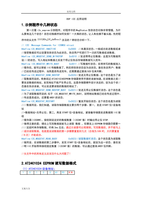
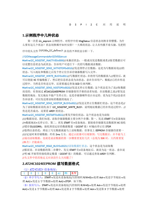
//头文件中的其他定义应该没什么大问题了!2.AT24C1024 EEPROM读写数据格式1 0 1 0 0 A1 P0 R/W(2)单字节写入:START -> 发送从设备地址(写控制码R/W=0) -> 处理Ack -> 发送字节地址 -> 处理Ack [-> 发送1字节数据 -> 处理Ack] -> STOP。
如下图:(3)按页写入:START -> 发送从设备地址(写控制码R/W=0) -> 处理Ack -> 发送字节地址 -> 处理Ack [-> 发送1字节数据 -> 处理Ack-> 发送第2字节数据 -> 处理Ack-> 发送第3字节数据 -> 处理Ack……直到发完X字节] -> STOP。
如下图。
注意,连续写入的数据字节数不能超过每页所能容下的总量。
如果写入的数据超过一页的长度,将发生回卷,即从EEPROM的0地址处进行数据覆盖。
比如,AT24C1024有512页,每页最大容纳256字节。
超过这个长度,地址指针将从每页首地址重新开始。
(4)随机单字节读取:第一步:发START -> 发送从设备地址(写控制码R/W=0) -> 处理Ack -> 发送字节地址高位 -> 处理Ack -> 发送字节地址低位 -> 处理Ack ->第二步:发START -> 发送器件地址(读控制码R/W=1) -> 处理Ack -> 接收1字节数据 -> STOP。
(5)随机连续读取:在随机单字节读取操作的STOP信号发送之前,加入若干个[-> 发送Ack -> 接收1字节数据] 即可实现。
(6)当前位置单字节读取:START -> 发送从设备地址(读控制码) -> 处理Ack -> 发送字节地址 -> 处理Ack -> 接收1字节数据 -> STOP。
当前指的是之前进行过读取操作但是没有发送STOP信号,EEPROM芯片内部指针所在的位置即为当前位置。
(7)当前位置连续读取:在当前位置单节读取操作的STOP信号发送之前,加入若干个 [-> 发送Ack -> 接收1字节数据] 即可实现。
备注:部分内容引用百度文库中的《I2C读写流程》文档3.主程序说明及流程图详细的注释可以参见程序附录,,这里主要解释一下设备地址取0x50的缘由。
从AT24C1024的数据手册可知,设备地址为。
而在程序中设置的地址是0x50,即0B0101 0000。
看似不妥,其实,这个例子中设备地址采用7位地址模式,这样只取0x50的低7位作为设备地址的高七位,设备地址的最低位R/W则由寄存器I2CMDR中的TRX位决定。
这样读数据时设备地址为0B1010 0001,写数据时设备地址改为0B1010 0000。
通过示波器可以验证这些数据。
问题1:每次检测到SCD中断时,也就是顺利发完指定数量的数据或者接收指定数量的数据了,理论上I2caRegs.I2CCNT==0,但是本人设了几个中断点去观察该寄存器的值,发现总是不为零。
通过观察I2caRegs.I2CFFTX.bit.TXFFST和I2caRegs.I2CFFRX.bit.RXFFST,可以发现这两个寄存器为零时,I2caRegs.I2CCNT也不为零。
由此可知,I2CCNT不能实时反映发送/接收存储器中数据的数量,不过可以用TXFFST/RXFFST来代替。
图1 主程序流程图,图2为写数据程序流程图,图3为读数据程序流程图,图4为中断函数流程图。
图1 主程序流程图图2写数据程序流程图图3读数据程序流程图图4中断函数流程图4.程序附录//可以用以下代码替换示例程序Example_280xI2c_eeprom.c中的代码,再进行调试。
// //该程序跟原始程序没多大区别,主要改变为:引入几个统计变量,改变发送数据长度为2字节// // TI File $Revision: /main/5 $// Checkin $Date: April 4, 2007 17:18:36 $//###########################################################################//// FILE: Example_280xI2c_eeprom.c//// TITLE: DSP280x I2C EEPROM Example//// ASSUMPTIONS://// This program requires the DSP280x header files.//// This program requires an external I2C EEPROM connected to// the I2C bus at address 0x50.//// As supplied, this project is configured for "boot to SARAM"// operation. The 280x Boot Mode table is shown below.// For information on configuring the boot mode of an eZdsp,// please refer to the documentation included with the eZdsp,//// Boot GPIO18 GPIO29 GPIO34// Mode SPICLKA SCITXDA// SCITXB// -------------------------------------// Flash 1 1 1// SCI-A 1 1 0// SPI-A 1 0 1// I2C-A 1 0 0// ECAN-A 0 1 1// SARAM 0 1 0 <- "boot to SARAM"// OTP 0 0 1// I/0 0 0 0//// DESCRIPTION://// This program will write 1-14 words to EEPROM and read them back.// The data written and the EEPROM address written to are contained// in the message structure, I2cMsgOut1. The data read back will be// contained in the message structure I2cMsgIn1.// --------------------------------------------------------------// CODE MODIFICATIONS ARE REQUIRED FOR 60 MHZ DEVICES (In// DSP280x_Examples.h in the common/include/ directory, set// #define CPU_FRQ_60MHZ to 1, and #define CPU_FRQ_100MHZ to 0).// --------------------------------------------------------------// This program will work with the on-board I2C EEPROM supplied on// the F280x eZdsp.//////###########################################################################// Original Author: D.F.//// $TI Release: DSP280x Header Files V1.60 $// $Release Date: December 3, 2007 $//############################################################################include "DSP280x_Device.h" // DSP280x Headerfile Include File#include "DSP280x_Examples.h" // DSP280x Examples Include File// Note: I2C Macros used in this example can be found in the// DSP280x_I2C_defines.h file// Prototype statements for functions found within this file.void I2CA_Init(void);Uint16 I2CA_WriteData(struct I2CMSG *msg);Uint16 I2CA_ReadData(struct I2CMSG *msg);interrupt void i2c_int1a_isr(void);void pass(void);void fail(void);#define I2C_SLAVE_ADDR 0x50 //EEPROM地址#define I2C_NUMBYTES 2 //为方便示波器观察,设置发送2字节的数据#define I2C_EEPROM_HIGH_ADDR 0x11 //数据的写入地址高位#define I2C_EEPROM_LOW_ADDR 0x0F //数据的写入地址低位// Global variables//全局变量// Two bytes will be used for the outgoing address,//有2个字节是地址// thus only setup 14 bytes maximum//最多只能设置14字节数据struct I2CMSG I2cMsgOut1={I2C_MSGSTAT_SEND_WITHSTOP,//初始状态为:发送带停止位数据I2C_SLAVE_ADDR,I2C_NUMBYTES,I2C_EEPROM_HIGH_ADDR,I2C_EEPROM_LOW_ADDR,0xff, // Msg Byte 010x3F, // Msg Byte 020x56, // Msg Byte 030x78, // Msg Byte 040x9A, // Msg Byte 050xBC, // Msg Byte 060xDE, // Msg Byte 070xF0, // Msg Byte 080x11, // Msg Byte 090x10, // Msg Byte 100x11, // Msg Byte 110x12, // Msg Byte 120x13, // Msg Byte 130x12, // Msg Byte 14};struct I2CMSG I2cMsgIn1={ I2C_MSGSTAT_SEND_NOSTOP,I2C_SLAVE_ADDR,I2C_NUMBYTES,I2C_EEPROM_HIGH_ADDR,I2C_EEPROM_LOW_ADDR};struct I2CMSG *CurrentMsgPtr; // Used in interruptsUint16 PassCount;Uint16 FailCount;Uint16 ARDY_ISRC_NACK_number=0; //统计ARDY中断源引起的中断中NACK次数Uint16 SCD_ISRC_number=0; //统计SCD中断源引起的中断次数Uint16 ARDY_ISRC_number=0; //统计ARDY中断源引起的中断次数Uint16 all_ISRC_number=0; //统计所有中断源引起的中断次数Uint16 Write_load_num=0; //统计写数据函数调用次数Uint16 Read_load_num1=0; //统计读数据函数调用次数1第一步骤Uint16 Read_load_num2=0; //统计读数据函数调用次数2第二步骤void main(void){Uint16 Error;Uint16 i;CurrentMsgPtr = &I2cMsgOut1;// Step 1. Initialize System Control:// PLL, WatchDog, enable Peripheral Clocks// This example function is found in the DSP280x_SysCtrl.c file.InitSysCtrl();// Step 2. Initalize GPIO:// This example function is found in the DSP280x_Gpio.c file and// illustrates how to set the GPIO to it's default state.// InitGpio();// Setup only the GP I/O only for I2C functionalityInitI2CGpio();// Step 3. Clear all interrupts and initialize PIE vector table:// Disable CPU interruptsDINT;// Initialize PIE control registers to their default state.// The default state is all PIE interrupts disabled and flags// are cleared.// This function is found in the DSP280x_PieCtrl.c file.InitPieCtrl();// Disable CPU interrupts and clear all CPU interrupt flags:IER = 0x0000;IFR = 0x0000;// Initialize the PIE vector table with pointers to the shell Interrupt// Service Routines (ISR).// This will populate the entire table, even if the interrupt// is not used in this example. This is useful for debug purposes.// The shell ISR routines are found in DSP280x_DefaultIsr.c.// This function is found in DSP280x_PieVect.c.InitPieVectTable();// Interrupts that are used in this example are re-mapped to// ISR functions found within this file.EALLOW; // This is needed to write to EALLOW protected registers PieVectTable.I2CINT1A = &i2c_int1a_isr;EDIS; // This is needed to disable write to EALLOW protected registers// Step 4. Initialize all the Device Peripherals:// This function is found in DSP280x_InitPeripherals.c// InitPeripherals(); // Not required for this exampleI2CA_Init();// Step 5. User specific code// Clear CountersPassCount = 0;FailCount = 0;// Clear incoming message bufferfor (i = 0; i < I2C_MAX_BUFFER_SIZE; i++){I2cMsgIn1.MsgBuffer[i] = 0x0000;}// Enable interrupts required for this example// Enable I2C interrupt 1 in the PIE: Group 8 interrupt 1PieCtrlRegs.PIEIER8.bit.INTx1 = 1;// Enable CPU INT8 which is connected to PIE group 8IER |= M_INT8;EINT;// Application loopfor(;;){//////////////////////////////////// Write data to EEPROM section ////////////////////////////////////// Check the outgoing message to see if it should be sent.// In this example it is initialized to send with a stop bit.if(I2cMsgOut1.MsgStatus == I2C_MSGSTAT_SEND_WITHSTOP){ Write_load_num++;Error = I2CA_WriteData(&I2cMsgOut1);// If communication is correctly initiated, set msg status to busy//如果通信已经正确初始化,设置msg状态为’忙‘,并// and update CurrentMsgPtr for the interrupt service routine. //更新作为中断服务路径的指针CurrentMsgPtr。