Gold recovery from parts-per-trillion-level aqueous solutions by a nanostructured Mn2O3 adsorbent
- 格式:pdf
- 大小:425.45 KB
- 文档页数:7
废旧镀金件回收工艺流程英文回答:The process of recycling waste gold-plated items involves several steps that are aimed at separating the gold from the other materials and refining it for reuse. Let me explain the process in detail.1. Collection: The first step is to collect the waste gold-plated items. These can include old jewelry,electronic components, or any other items that have a layer of gold plating on them. These items are usually obtained from individuals, jewelry stores, or electronic waste recycling centers.2. Sorting: Once the items are collected, they need to be sorted based on their composition. This is important because different materials may require different recycling methods. For example, if the gold-plated items also contain other precious metals like silver or platinum, they need tobe separated first.3. Dismantling: After sorting, the gold-plated itemsare dismantled to remove any non-gold materials. This may involve cutting, grinding, or melting the items to separate the gold layer from the base material. For example, in the case of electronic components, the gold-plated pins or connectors are removed from the circuit boards.4. Chemical Treatment: The next step is to treat the gold-plated items with chemicals to dissolve the gold layer. This can be done using a combination of acids, such asnitric acid or aqua regia. The chemicals react with the gold, leaving behind other impurities.5. Filtration: Once the gold is dissolved, the solution is filtered to remove any solid impurities. This ensuresthat only the gold-containing solution remains.6. Precipitation: The filtered solution is then treated with a reducing agent, such as sodium metabisulfite oroxalic acid, to precipitate the gold. This causes the goldto form solid particles that can be easily separated fromthe solution.7. Refining: The precipitated gold particles arefurther refined to remove any remaining impurities. Thiscan be done through processes like smelting or electrolysis. The end result is pure gold that can be used for various purposes.8. Reuse or Sale: Finally, the refined gold can be reused for manufacturing new gold-plated items or sold to gold refineries or jewelry manufacturers.中文回答:废旧镀金件回收的工艺流程包括几个步骤,旨在将金与其他材料分离并提炼出可再利用的金。
回收贵金属的利弊英语作文Pros and Cons of Recycling Precious Metals。
Recycling precious metals has become a popular way tonot only reduce waste but also to recover valuable resources. However, like any other practice, there are both advantages and disadvantages to consider. In this essay, we will explore the pros and cons of recycling precious metals.Pros:1. Environmental Benefits: One of the most significant advantages of recycling precious metals is the positive impact it has on the environment. By reusing these materials, we can reduce the need for mining and extraction, which can be harmful to the environment. Additionally, recycling precious metals reduces the amount of waste that ends up in landfills, further reducing the environmental impact.2. Conservation of Resources: Precious metals arefinite resources, and recycling them allows us to conserve these valuable materials for future generations. By reusing and repurposing these metals, we can extend their lifespan and reduce the need for new mining and extraction.3. Economic Benefits: Recycling precious metals can also have economic benefits. By recovering and reusing these materials, we can reduce the demand for newly mined metals, which can help stabilize prices. Additionally, recycling can create jobs in the recycling and refining industries, contributing to the economy.4. Energy Savings: Recycling precious metals requires less energy than mining and refining new materials. This can lead to significant energy savings and reduced greenhouse gas emissions, further benefiting the environment.Cons:1. Cost and Complexity: While recycling precious metalscan be beneficial, it is also a complex and costly process. Recovering and refining these materials requiresspecialized equipment and expertise, which can be expensive. Additionally, the process of separating and purifying the metals can be complicated and time-consuming.2. Contamination: Precious metals can become contaminated during the recycling process, reducing their purity and value. Contamination can occur from impuritiesin the materials being recycled or from the use of improper recycling techniques. This can make it more difficult to reuse the metals in high-value applications.3. Limited Supply: While recycling can help conserve precious metals, it is not a limitless source. Eventually, the supply of recycled metals may not be enough to meet demand, leading to the need for new mining and extraction.4. Environmental Impact: While recycling preciousmetals can have environmental benefits, the process itself can also have negative environmental impacts. The use of chemicals and the generation of waste during the refiningprocess can contribute to pollution and environmental degradation.In conclusion, recycling precious metals has both advantages and disadvantages. While it can have significant environmental and economic benefits, it also comes with costs and complexities. As the demand for these valuable resources continues to grow, it is important to carefully consider the pros and cons of recycling precious metals and work towards finding sustainable solutions for their recovery and reuse.。
金子首饰赏析英文作文高中英文回答:Jewelry, a testament to human creativity and ingenuity, has been an integral part of adornment for centuries. From intricate necklaces to elegant earrings, gold jewelry has captivated hearts with its timeless beauty and intrinsic value.Gold, the precious metal, embodies both allure and durability. Its warm, lustrous glow evokes a sense of opulence, while its exceptional malleability allows for intricate craftsmanship. Gold jewelry, therefore, represents a harmonious blend of art and functionality.Necklaces, draped elegantly around the neck, add a touch of sophistication to any outfit. Gold necklaces come in a myriad of designs, from delicate chains to statement-making pendants.Intricate earrings, adorning the ears, draw attention to the face and frame the features. Gold earrings offer a wide range of styles, from classic studs to elaborate chandeliers.Bracelets, encircling the wrist, lend a touch of charm and elegance. Gold bracelets come in various forms, from sleek bangles to ornate cuffs.Rings, worn on fingers, symbolize commitment, love, and personal style. Gold rings come in a vast array of designs, from simple bands to elaborate engagement rings.Gold jewelry, whether a cherished heirloom or a contemporary masterpiece, evokes a sense of timeless elegance and personal connection. Its versatility allows it to complement both formal attire and casual wear, making it an enduring favorite among jewelry enthusiasts worldwide.中文回答:黄金首饰赏析。
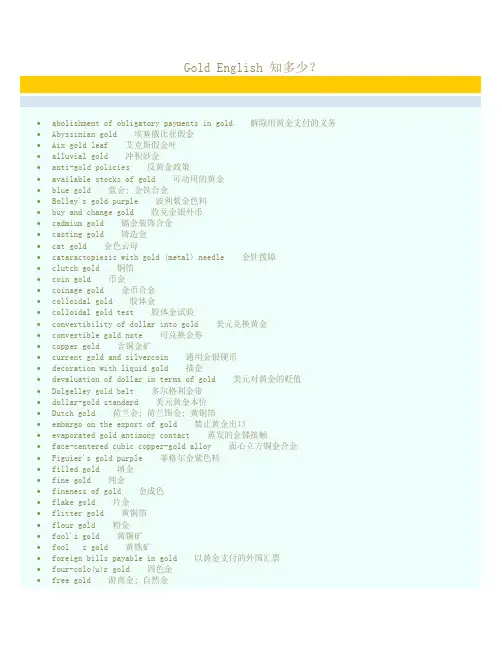
Gold English 知多少?∙abolishment of obligatory payments in gold 解除用黄金支付的义务∙Abyssinian gold 埃塞俄比亚假金∙Aix gold leaf 艾克斯假金叶∙alluvial gold 冲积砂金∙anti-gold policies 反黄金政策∙available stocks of gold 可动用的黄金∙blue gold 蓝金; 金铁合金∙Bolley's gold purple 波利紫金色料∙buy and change gold 收兑金银外币∙cadmium gold 镉金装饰合金∙casting gold 铸造金∙cat gold 金色云母∙cataractopiesis with gold (metal) needle 金针拨障∙clutch gold 铜箔∙coin gold 币金∙coinage gold 金币合金∙colloidal gold 胶体金∙colloidal gold test 胶体金试验∙convertibility of dollar into gold 美元兑换黄金∙convertible gold note 可兑换金券∙copper gold 含铜金矿∙current gold and silvercoin 通用金银硬币∙decoration with liquid gold 描金∙devaluation of dollar in terms of gold 美元对黄金的贬值∙Dolgelley gold belt 多尔格利金带∙dollar-gold standard 美元黄金本位∙Dutch gold 荷兰金; 荷兰饰金; 黄铜箔∙embargo on the export of gold 禁止黄金出口∙evaporated gold antimony contact 蒸发的金锑接触∙face-centered cubic copper-gold alloy 面心立方铜金合金∙Figuier's gold purple 菲格尔金紫色料∙filled gold 填金∙fine gold 纯金∙fineness of gold 金成色∙flake gold 片金∙flitter gold 黄铜箔∙flour gold 粉金∙fool's gold 黄铜矿∙fool s gold 黄铁矿∙foreign bills payable in gold 以黄金支付的外国汇票∙four-colo(u)r gold 四色金∙free gold 游离金; 自然金∙free gold bullion basis 金块的自由输出入∙free gold reserve 可动用的黄金储备∙free-milling gold 易汞齐化金∙French gold 铜锌锡合金∙Fuch's gold purple 福契氏紫金颜料∙fulminating gold 雷酸金∙germanium-gold eutectic mixture 锗金低共熔混合物∙gold 金; 黄金∙gold 18 carats pure 十八开金∙gold alloy solder 金合金焊∙gold analyzer 黄金含量分析仪∙gold and silver assay 金银鉴定∙gold and silver control 金银管理∙gold assay 金鉴定∙gold auctions 拍卖黄金∙gold blackbody 金黑体∙gold blocking 烫金∙gold bond 以黄金偿付的债券∙gold bonding wire 金键合线; 金连接线∙gold bonds 金债券∙gold brick 金砖∙gold bronze 金青铜∙gold bullion 金锭∙gold bullion market 金块市场∙gold bullion standard 金块本位; 纯金本位制∙gold bullion standard system 金块本位制∙gold card 金卡∙gold certificate 金券∙gold certificate (美国) 金库券∙gold chloride 氯化金∙gold coin and bullion 金币和金块∙gold coin clause 金币条款∙gold coin standard 金币本位; 金铸币本位制∙gold coin standard system 金铸币本位制∙gold coins 金币∙gold colloidal 放射性胶体金∙gold currency 金本位货币∙gold currency standard 金通货本位制∙gold currency standard system 金本位制∙gold cushion 烫金垫∙gold cyanide 氰化金∙gold detector 黄金探测器∙gold dichloride 二氯化金∙gold dioxide 二氧化金∙gold dollar bill 美币票据∙gold doping 掺金∙gold dredger 采金船∙gold dust 金粉∙gold embargo 禁止黄金出口∙gold exchange 金汇兑∙gold exchange standard 金币兑换制∙gold exchange standard (GES) 金汇兑本位制∙gold exchange standard system 金汇兑本位制∙gold filigree 金属镶嵌∙gold film mercury detector 金膜测汞仪∙gold fix 议定金价∙gold foil 金箔∙gold franc 金法郎∙gold hydroxide 氢氧化金∙gold ingot 金锭∙gold issues 金矿股票∙gold laser 金激光器∙gold mines index 金矿指数∙gold mining 采掘黄金∙gold money 金币; 金货币∙gold number 金值∙gold number test 金值试验∙gold ore 金矿∙gold oxide 氧化金∙gold parity 金平价∙gold pin porcelain tooth 黄金钉瓷牙∙gold plate scissors 金片剪∙gold plated contact 镀金触点∙gold plated frame 镀金镜架∙gold plated PVC flexible hose 镀金聚氯乙烯软管∙gold plated watch bracelet 镀金表链∙gold plating 镀金∙gold plating thickness 镀金厚度∙gold plugger 金箔充填器械∙gold point 金点; 输金点∙gold polyneuritis 金中毒性多神经炎∙gold potassium chloride 氯化金钾∙gold potassium cyanide 氰化亚金钾∙gold powder 金粉∙gold premium policy 金币升水政策∙gold price fluctuations 金价波动∙gold ripeness 黄熟∙gold rush 淘金热∙gold salt 氯化钠金∙gold sandwich contact 金夹层接触∙Gold schmidt 铝热焊∙gold shares 金矿股票∙gold size 金胶; 贴金漆∙Gold slide 戈尔德计算尺∙gold sodium chloride 氯化钠金∙gold sodium cyanide 氰化钠金∙gold sodium thiomalate 硫代苹果酸金钠∙gold sodium thiosulfate 硫代硫酸钠金∙gold solder 金焊∙gold specie standard 金币本位∙gold spot 金斑病∙gold spring 金簧∙gold stamping 烫金∙gold standard 金本位; 金本位制∙gold standard act 金本位制法∙gold standard system 金本位制∙gold sterilization 限制黄金作用的货币政策∙gold sterilization policy 限制黄金作用的货币政策∙gold stomatitis 金毒性口炎∙gold stoving varnish 金色烤漆∙gold tail moth 桑毛虫∙gold tooling 烫金工具∙gold tribromide 三溴化金∙gold trichloride 三氯化金∙gold tricyanide 三氰化金∙gold trihydroxide 三氢氧化金∙gold trioxid 三氧化二金∙gold trisulfide 三硫化二金∙gold-black coating 金黑涂层∙gold-bonded contact 金键合接触∙gold-bonded diode 金键二极管∙gold-bricking 限制生产定额∙gold-doped 掺金的∙gold-doped germanium 锗掺金∙gold-doped germanium detector 掺金锗探测器∙gold-doped germanium infrared detector 掺金锗红外探测器∙gold-doped transistor 掺金型晶体管∙gold-filled 包金∙gold-film glass 包金膜玻璃; 涂金膜玻璃∙gold-imitation processing technology 仿金工艺技术∙gold-overlaid 贴金∙gold-plating 镏金∙gold-platinum alloy clasp-wire 金铂合金卡环丝∙gold-point blackbody 金点黑体∙gold-secured loans 以黄金作抵押的贷款∙gold-sol reaction 金胶液试验∙gold-sol test 金胶液试验∙gold-vanadium alloy 金钒电阻合金∙greasy gold 纯金∙green gold 绿金∙gulch-gold 砂金∙high-purity gold 高成色黄金∙honey-gold 蜜黄色∙hot-pressed gold 热压金∙Hume gold flow equilibrating mechanism 休姆黄金流动平衡作用∙imitation gold yarn 充金线∙import gold point 进口黄金点∙instability of gold market prices 市场金价的不稳定∙isinglass gold-size 鱼胶贴金漆∙Japanese blue gold 日本蓝金∙lacquer with gold design 描金漆器∙legal gold content 法定含金量∙legally prescribed gold content 法定含金量∙liquid bright gold 液体亮金∙liquid palladium gold 钯金水∙lode gold 脉金∙London gold market 伦敦黄金市场∙Manila gold 马尼拉假金∙Manilla gold 铅黄铜∙Mannheim gold 曼海姆金; 曼海姆铜锌锡代金合金∙milk gold 乳金∙minimum ratio of gold reserve 最低黄金准备比率∙Mock gold 莫克金; 莫克铜铂合金; 铂铜合金∙mosaic gold 仿金铜箔∙Mosaic gold 莫塞克黄铜型假金; 铜锌合金∙mosaic gold alloy 嵌镶金合金∙moss gold 苔状金∙mountain gold 山金∙mussel gold (色料) 淡菜金∙native gold 自然金∙new gold exchange standard system 新金汇本位制∙non-monetary gold 非货币性黄金∙nonmonetarized gold 非货币化黄金∙nonmonetary gold 非货币化黄金∙Nuremberg gold 铜铝金装饰合金∙off the gold standard 放弃金本位∙official gold content 法定含金量∙official gold price 法定金价∙official stipulation on the gold content 法定含金量∙open-face gold crown 露面金冠∙palladium-gold polarium 钯金合金∙paper gold (国际货币基金组织特别提款权的别称) 纸黄金∙parity of gold and silver 金银比价∙pink gold 金银铜镍装饰合金∙potassium gold chloride 氯化金钾∙potassium gold cyanide 氰化亚金钾∙powdered gold 粉化金∙primary gold-bearing sulfide 原生含金硫化物∙proof gold 纯金∙proof gold (试金用) 标准金∙pure gold 纯金; 赤金; 足金∙raise gold content 提高含金量∙Ranvier's gold chloride staining method 朗飞氏氯化金染色法∙ratio of gold and silver 金银比价∙red gold 纯金∙red gold alloy 红金合金∙reef gold 石英脉金∙refractory gold 难选金∙rich gold metal 金争黄铜∙rolled gold 轧制金箔; 金箔; 包金∙rolled gold watch 包金表∙run on gold against US dollars 美元挤兑黄金的风潮∙rusty gold 锈金; 难混汞的金; 自然金∙seamless gold crown 无缝金壳冠∙self-recording gold-leaf electroscope 自记式金箔验电器∙sintered gold 烧结金∙sodium gold chloride 氯化钠金∙sodium gold cyanide 氰化钠金∙solid gold 纯金; 赤金; 足金∙solid-gold chain 纯金项链∙solid-gold pendant 纯金挂件∙spring gold 弹簧金∙standard gold 标金; 标准金∙sterling gold 标准纯金∙stream gold 河金∙suspension of the dollar's conversion into gold 美元停止兑换黄金∙Swiss gold franc 瑞士金法郎∙Swiss gold-trading pool 瑞士黄金联营∙Talmi gold 镀金黄铜∙tilted gold-leaf electrometer 倾斜金箔静电计∙two-tier gold market 双重黄金市场∙two-tier gold price system 双重金价制∙Waechtler's gold purple 威奇特勒紫金色料∙white gold 白金∙white gold alloy 白色金银合金∙white gold jewelry alloy 白金首饰合金∙white gold solder 白金焊料∙winnowing gold 风选金矿法∙yellow gold 金银铜合金∙yelow gold 黄银铜合金。
1金砖的烧造历史用砖、石所铺墁的地面,在清官式做法中称作“墁地”,紫禁城所用的墁地砖大都使用产自山东临清的城砖和产自苏州一带的金砖。
我国铺墁地砖的历史从两千多年前的春秋时期就已出现,但其材质、工艺等与金砖无法相比[1]。
金砖,明代称之为细料方砖,清代改称为金砖,是皇家建筑专用的一种高规格铺地材料,属于钦工物料,即便是残次或者废弃的金砖也要严格管理,不得流向民间[2]。
1.1金砖的产地、规制尺寸和款识明永乐年间,明成祖朱棣迁都北京后大兴土木建造紫禁城,经由苏州香山帮工匠的推荐,陆慕砖窑被工部选中,由于产砖质量优良,受到永乐皇帝的称赞,赐名窑场为“御窑”[3]。
从历史档案中也可获知,万历本《大明会典》卷一百九十记载:“凡遇营建宫殿,苏州窑烧造细料方砖”,康熙本《苏州府志》卷十二记载:“窑作,出齐门陆慕,工部用官砖,于此烧造”,也说明明清两代皇家宫殿所用金砖多产自苏州一带。
金砖通常有一尺七寸、二尺、二尺二寸三种尺寸规格,见图1和图2。
明代至清雍正时期,所造金砖只有一尺七寸和二尺两种规格,在乾隆时期出现了二尺二寸金砖的记录。
乾隆四年六月初九日江苏巡抚张渠在奏折称“尚有二尺二寸金砖,砖身俞大,烧造愈难,且事属创始”,乾隆二十九年颁布的《钦定大清会典》明确:苏州窑金砖“大者方二尺二寸,次二尺,次尺有七寸”,从此金砖的三种烧造尺寸便确定下来。
出窑的每块金砖都详细铭刻金砖的款识,记录烧造此砖的相关信息,包含官款(官员姓名、官职、属地)、年款(名称、尺寸、年号)、窑款(窑户姓名、里甲)等内容,使用款识的目的主要便于追究责任,以备查验和惩处。
1.2金砖的选材及烧制工艺苏州河床内有多年沉积的泥沙,质地细腻,含铁量浅析故宫古建筑室内金砖及其保护修复研究——以太和殿为例房晓明(故宫博物院,北京100009)摘要:苏州等五府烧造的金砖作为钦工物料在明清宫殿中使用十分广泛,是皇家建筑中铺地所使用的高规格细料方砖,主要应用于宫殿、坛庙、陵寝等高等级官式建筑,其缝严如骔、光似墨玉、坚硬密实。
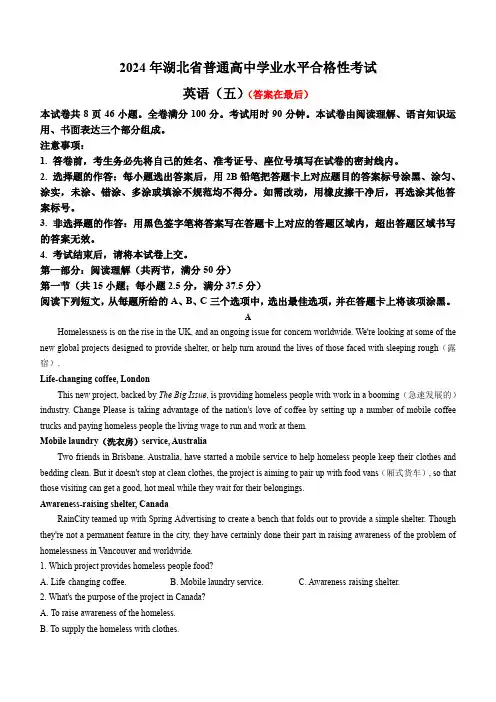
2024年湖北省普通高中学业水平合格性考试英语(五)(答案在最后)本试卷共8页46小题。
全卷满分100分。
考试用时90分钟。
本试卷由阅读理解、语言知识运用、书面表达三个部分组成。
注意事项:1. 答卷前,考生务必先将自己的姓名、准考证号、座位号填写在试卷的密封线内。
2. 选择题的作答:每小题选出答案后,用2B铅笔把答题卡上对应题目的答案标号涂黑、涂匀、涂实,未涂、错涂、多涂或填涂不规范均不得分。
如需改动,用橡皮擦干净后,再选涂其他答案标号。
3. 非选择题的作答:用黑色签字笔将答案写在答题卡上对应的答题区域内,超出答题区域书写的答案无效。
4. 考试结束后,请将本试卷上交。
第一部分:阅读理解(共两节,满分50分)第一节(共15小题;每小题2.5分,满分37.5分)阅读下列短文,从每题所给的A、B、C三个选项中,选出最佳选项,并在答题卡上将该项涂黑。
AHomelessness is on the rise in the UK, and an ongoing issue for concern worldwide. We're looking at some of the new global projects designed to provide shelter, or help turn around the lives of those faced with sleeping rough(露宿).Life-changing coffee, LondonThis new project, backed by The Big Issue, is providing homeless people with work in a booming(急速发展的)industry. Change Please is taking advantage of the nation's love of coffee by setting up a number of mobile coffee trucks and paying homeless people the living wage to run and work at them.Mobile laundry(洗衣房)service, AustraliaTwo friends in Brisbane, Australia, have started a mobile service to help homeless people keep their clothes and bedding clean. But it doesn't stop at clean clothes, the project is aiming to pair up with food vans(厢式货车), so that those visiting can get a good, hot meal while they wait for their belongings.Awareness-raising shelter, CanadaRainCity teamed up with Spring Advertising to create a bench that folds out to provide a simple shelter. Though they're not a permanent feature in the city, they have certainly done their part in raising awareness of the problem of homelessness in Vancouver and worldwide.1. Which project provides homeless people food?A. Life-changing coffee.B. Mobile laundry service.C. Awareness-raising shelter.2. What's the purpose of the project in Canada?A. To raise awareness of the homeless.B. To supply the homeless with clothes.C. To teach the homeless how to earn a living.3. Who are the targeted people for these three projects?A. The poor.B. The homeless.C. The hungry.BWhen Ariel Cordova rode her bike to Jamaica Bay Wildlife Refuge in Queens, New York, last November, she planned to go hiking and bird-watching. A mile into her walk, she spotted a beautiful female mute swan near the water's edge. Cordova, 30, who had worked at the Wild Bird Fund recovery center, knew that mute swans can be aggressive(侵略性的). But as she approached this one, it didn't move.She was certain that the bird needed medical attention. Cordova draped(披,悬挂)her jacket over the bird's head to keep it calm, carefully picked it up, and held it gently in her arms. She was wondering how to transport a 17-pound swan on her bike to the recovery center when, luckily, some confused strangers driving by offered her, her bike, and the swan a lift to a nearby subway station. Cordova called the recovery center on the way, and Tristan, an animal care manager, picked her up at the subway station and drove the bird, the bike, and the rescuer to the facility(场所). There, staff members determined that the swan might have lead(铅)poisoning. Sadly, even with all that tender loving care, the swan got contracted, which caused her passed away two months after being rescued.It's a disappointing ending, but the real story is just how far some people are willing to go to save a swan in the big city. In all, Cordova traveled two hours by foot, car, and subway. "That's the perfect summary of who she is," says Tristan.4. What made Cordova believe the bird needed medical attention?A. Its careful move.B. Its aggressive nature.C. Its unusual behavior.5. How did Cordova finally get to the recovery center?A. She walked two hours.B. A manager took her by car.C. Some stranger picked her up.6. What does the underlined word "contracted" in Paragraph 2 mean?A. Infected.B. Rescued.C. Killed.7. Which of the following can best describe Cordova?A. Caring.B. Demanding.C. Professional.CThe Asian Games are a comprehensive(综合性的)sport event in Asia, organized by the Asian Olympic Council every four years. The first Asian Games were held in New Delhi, India in 1951. China has hosted two Asian Games in Beijing and Guangzhou in 1990 and 2010 respectively.Compared with other international comprehensive sports events, the Asian Games have non-Olympic sports. The Hangzhou Asian Games will be the largest comprehensive sports event in Asia ever, with 40 sports including 61 sub-ones and 481 gold medals to be awarded. There are symbolic sports representing Asia such as wushu, sepak takraw, cricket and ju-jitsu, and emerging ones that are popular with the youth such as skateboarding, sport climbing, e-sports and breaking(霹雳舞), with the latter two newly-introduced in this Games. The Hangzhou Asian Games will present the diversity and inclusiveness(包容性)of Asian sports culture.Boasting the West Lake and known as "paradise on earth", Hangzhou is one of the birthplaces of Chinese silk, calligraphy, painting, printing and seal cutting(篆刻), and a city with artistic conception and innovative vitality(活力), leading in the areas of Internet and digital economy in China.The Games' three mascots(吉祥物)named Chenchen, Congcong and Lianlian are three robots carrying cultural and modern meanings. The three represent the Liangzhu Archaeological Ruins, the West Lake and the Grand Canal in Hangzhou respectively.The city and the green, intelligent, cultural and civilized Asian Games are welcoming you.8. How many years has passed since the first Asian Games been held?A. Over seventy years.B. Over one century.C. Almost fifty years.9. What is special about Hangzhou Asian Games?A. It has a lot of non-Olympic sports.B. It will be introduced two new events.C. It is the largest sports event of all time.10. What is Hangzhou known for in terms of its industries?A. Clothes production.B. Oil and gas exploration.C. Internet and digital economy.11. What's Paragraph 4 mainly about?A. The places of interest in Hangzhou.B. The features of Hangzhou Asian Games.C. The mascots of Hangzhou Asian Games.DWalk along any beach in the world and you will find plastic of some kind washed up on the shoreline, offering a reminder(提醒人的事物)of the throwaway culture of the present day world. Now, a new study has sounded a fresh warning on the damage caused to the marine ecosystem(海洋生态系统)due to plastics thrown away, which finally has an effect on human health due to the seafood we eat.In a paper titled A Growing Plastic Smog published on March 8 in the research journal Plos One, researchers called on governments around the world to take thorough action to address the "plastic pollution" of the world's oceans.No one knows for certain what the long-term damage will be to marine life and humans, but the study placed the blame on the plastics industry for failing to recycle or design for recyclability.Marcus Eriksen, lead author of the study, said in a statement that the findings were a "obvious warning that we must act now at a global scale". "We've found an alarming trend of exponential(指数的)growth of microplastics in the global ocean since the millennium(千禧年), reaching over 170 trillion plastic particles," said Eriksen, adding that the exponential increase in microplastics across the world's oceans makes it essential to guide in an age of shared responsibility for the entire life of the things they make.12. What does the new research's finding focus on?A. The polluted seafood.B. The bad effect of plastic pollution.C. The damage caused by marine ecosystem.13. Who should take responsibility for the damage caused by plastic pollution?A. The plastics industry.B. Governments.C. Common people.14. What is Marcus Eriksen's attitude to the increasing microplastics in the ocean?A. Doubtful.B. Unclear.C. Concerned.15. What is the suggested solution to the issue of plastic pollution?A. Banning plastic production.B. Designing recyclable plastics.C. Promoting shared responsibility.第二节(共5小题;每小题2.5分,满分12.5分)根据短文内容,从短文后的选项中选出能填入空白处的最佳选项,并在答题卡上将该项涂黑。
外文文献Gold refining technology introductionGold ore in the content is extremely low, in order to extract gold, need to will be broken and fine grinding ore and adopt。
With the mineral processing or enrichment from ore in advance that gold is isolated. Gold ore dressing is used in moreRe-election and flotation, re-election method in ShaJin production in an important position, flotation method is rock gold mine。
Widely use of mineral processing mountain, at present our country about 80% of the rock gold mines use this law to choose gold, choose。
Ore technology and equipment level is distinctly improved.(A) Broken and grindingAccording to the survey, our country choose gold in the jaw crusher for crushing, using standard cone broken. Ore machine broken, and finely used the short head type tapered roller machine and broken mine to break mine machine. Medium and small choose.Gold factory is used mostly for two broken a closed-circuit ore, large choose the three sections of a gold factory closed-circuit broken mine process. In order to improve the dressing production ability, mining equipment potential, broken mine to process, the reform.Grinding machine utilization coefficient increase, the major measures taken the little mill is broken, reduce ore into the ground particle size.(B) Re-electionRe-election in rock gold mine apply more extensive, and more as aided process, in the grinding loop of the recovery. Coarse grain of gold, for flotation and cyanide process to create favorable conditions, improve concentration index, improve the total return to gold. The yield, to increase production and reduce the cost is playing a positive role. Shandong province about more than 10 pick. Gold factory used heavy choose this one process, the average total recovery can be increased 2% ~ 3%, the enterprise economic effectGood profit, according to not complete count, may have millions of dollars a year of the profits. Henan, hunan, Inner Mongolia, etc. Provinces (areas) also have good effect, the main equipment is chute, wave bed, jig and short cone. Vortex machines etc. From our mostgold mine to see, float-heavy joint process (flotation tailings used heavy Choose) suitable for.(C) FlotationAccording to the survey, 80% of rock in the gold mines flotation method selected gold, the output of the concentrate more. Sent to non-ferrous smelter processing. Because of leaching gold cyanide process of development and enterprise to improve economic efficiency. Good, reduce concentrate transportation loss, in recent years the product structure has experienced a greater change, take more local processing (of course also because of mineral smelting and the contradiction between the problems and valuation, forcing the mine in situ to place Richard) prompted the flotation process have larger development, in the gold production occupies an important position in the. Usually Priority of flotation and mixing floatation two craft. In recent years in the process modification and potions add system .With new progress, flotation recoveries also increased significantly. More than 40 selected according to the national gold factory, flotation work.(D) The choose-leaching gold technology sector1. Mix mercury law of leaching goldMix mercury method of leaching gold process is a kind of old mention gold process, easy, and economic, and is suitable for coarse grains. Monomer recovery of gold. Our country many gold mine still follow the method. Along with the development of the gold production and the progress of science and technology, mix mercury law of leaching gold process is also constantly have improved and perfected. Due to the environment.The increasingly strict requirements, some mining cancelled mix mercury assignments, as heavy choose, the flotation and cyanide process of leaching gold.process replaced. In the gold production, mixed mercury method of leaching gold technology still has its important role in the domestic and foreign are should be with a practical example. At present in zhangjiakou, hebei province, liaoning erdaogou, jilin jiapigou, shandong etc many gold incorporated. Mine the process application. Liaoning erdaogou gold mine was a single flotation process, according to the ore properties instead.2. Of leaching gold cyanide process technologyCyanide process technology of leaching gold from oreconcentrate is modern or extraction of the main method of gold. Cyanide process mention.Gold technologies include: by roasting-cyanide leaching process, leaching of pulp washing filtering, kau liquid or are the cicc pulp.The extraction and the finished product and so on several basic processes of smelting. China's gold mines are the two basic existing factory. Kind of leaching gold process, one kind is dense continuous against washing machine, with zinc powder replacement precipitation back. The gold of so-called ordinary cyanide process of leaching gold process (CCD method and CCF law), the other is without filter washing, the active carbon adsorption in the pulp are directly from the recovery of gold without filter are carbon plasma process (CIP method and CIL law).Ordinary cyanide process of leaching gold process according to the different materials handled and two .(E) Heap leaching process for productionGold resources in China, low grade oxidation of ore has certain proportion, deal with this kind of ore.The routine of leaching gold cyanide process technology not economically viable, and the production process heap leaching, there are economic effect. The victims. Further expand the production scale heap leaching, is increase China's gold production of one of the path.20. At the end of the 70 s, China began to low grade contain gold ore heap leaching oxidation of the production process research, liaoning dandong hushan gold small-scale production trials are successful, successively in henan spirit lake, silver Hole slope, yunnan MoJiang, hebei worship ritual, Inner Mongolia and some of the mine in chifeng application, take more satisfactory economic effect, low grade for the gold ore containing the oxidation of the development and utilization of the opened up.。
Gold ExperienceIntroduction to Gold ExperienceGold Experience is an immersive and interactive event that offers a unique opportunity to explore the world of gold. This event brings together enthusiasts, experts, and industry professionals to provide an exciting and educational experience. Whether you are curious about the history and science behind gold, interested in investing in gold, or simply appreciate its beauty, Gold Experience is the perfect event for you.The History of GoldGold has fascinated humans for centuries. Its allure can be traced back to ancient civilizations, where it was revered as a symbol of wealth and power. The Egyptians adorned their pharaohs with gold jewelry, while the Greeks and Romans used it for coins and decorative arts. The discovery of gold in California in the mid-19th century sparked the famous gold rush, leading to a significant increase in gold production and the establishment of prosperous communities.The Science of GoldGold is a unique element with several remarkable properties. It is a highly malleable metal, which means it can be easily shaped and manipulated into intricate designs. It is also an excellent conductor of electricity, making it widely used in electronic components. Additionally, gold is resistant tocorrosion and tarnish, making it ideal for creating durable and long-lasting jewelry.Investing in GoldGold has always been considered a safe-haven investment. During times of economic uncertainty, gold tends to retain its value or even increase in price. It is seen as a hedge against inflation and a way to diversify investment portfolios. The Gold Experience event will provide valuable insights into various investment options, including physical gold, gold-backed securities, and gold mining stocks. Experts will share their knowledge and strategies to help attendees make informed investment decisions.Exploring Gold JewelryGold jewelry has been worn and cherished for centuries. It comes in various forms, including rings, necklaces, bracelets, and earrings. In addition to its aesthetic appeal, gold jewelry carries cultural and symbolic significance in different parts of the world. The Gold Experience event will showcase a wide range of stunning gold jewelry designs from different eras and cultures. Attendees will have the opportunity to learn about goldsmithing techniques and even try their hand at creating their own personalized gold jewelry.Gold Mining and Sustainable PracticesGold mining has a significant impact on the environment, and responsible and sustainable mining practices are crucial for preserving the natural ecosystem. The Gold Experience event will feature discussions and presentations on the latesttechnologies and practices in sustainable gold mining. Experts from the industry will share their knowledge on how mining companies are minimizing their environmental footprint and improving social responsibility.ConclusionGold Experience is a must-attend event for anyone interested in exploring the fascinating world of gold. With its rich history, scientific properties, investment potential, and stunning jewelry, gold has something to offer to everyone. Whether you are a collector, investor, or simply intrigued by its beauty, the Gold Experience event will provide a comprehensive and immersive experience. Join us for an unforgettable journey into the golden world of gold!。
黄金热降温后的末日生存者What happens when gold may no longer glitter enough to stave off the financial apocalypse?如果光彩耀眼的黄金再也不足以抵御金融灾难,情况会怎样呢?The precious metal, a big beneficiary at quantitative easing's outset as investors sought a hedge against possible inflation, has been steadily declining. During the first round of QE in December 2008, the price of gold was $837.50 an ounce. The precious metal's longer term run-up kicked into overdrive, with the price peaking in September 2011 at $1, 922. Of course, this ultimately represented a dependency trap -- in April the price dropped 30%, in part on fears that QE would be coming to an end. Today, gold sits at around $1, 371, a 20% drop in six months.美联储实施量化宽松之初,黄金是主要的受益者,原因是投资者纷纷设法防范可能出现的通货膨胀。
随后,黄金价格开始持续稳步下跌。
2008年12月首轮量化宽松期间,金价为每盎司837.50美元(5167.38元人民币)。
长时间的上涨造成金价过高,2011年9月黄金价格在1922美元(11858.74元人民币)见顶。
镀金件回收工艺流程英文回答:Gold-plating is a common process used in various industries, such as jewelry, electronics, and even aerospace. The process of recycling gold-plated items involves several steps to extract the gold from the plated surface. In this response, I will outline the general process of gold-plating recycling.1. Collection and Sorting:First, the gold-plated items are collected from various sources, such as discarded electronics, old jewelry, or industrial waste. These items are then sorted based ontheir type and composition. For example, jewelry items with different karatage or electronics with different plating thickness may require separate processing.2. Disassembly:Next, the collected items are disassembled to separate the gold-plated components from other materials. For instance, in the case of electronic waste, the circuit boards are separated from other components like plastic casings or connectors.3. Chemical Stripping:Once the gold-plated components are separated, they undergo a chemical stripping process to remove the gold layer. This process involves immersing the components in a specialized solution that dissolves the gold layer, leaving behind the base material. The stripped gold is then recovered from the solution through further chemical processes.4. Precious Metal Recovery:After the gold is stripped from the plated components, it is further processed to recover the pure gold. This can be done through various methods, such as electrolysis orsmelting. These processes separate the gold from any impurities or other metals present, resulting in a pure gold product.5. Refining and Purification:The recovered gold may still contain impurities, such as traces of other metals or contaminants. To ensure high purity, the gold is subjected to refining and purification processes. These processes involve further chemical treatments or melting to remove any remaining impurities and obtain a final product of high-quality gold.6. Reuse or Sale:Finally, the recycled gold can be reused in various applications or sold to gold refineries or manufacturers. The gold can be used to create new jewelry, electronic components, or even as an investment.中文回答:镀金件回收工艺流程涉及多个步骤,用于从镀金表面提取金。

电感耦合等离子体发射光谱法的英文简称全文共3篇示例,供读者参考篇1Inductively Coupled Plasma Optical Emission Spectroscopy (ICP-OES) is a powerful analytical technique used in many scientific fields. This technique utilizes the high temperature of a plasma to atomize and excite samples for elemental analysis. ICP-OES provides high sensitivity, accuracy, and precision, making it a popular choice for analyzing trace elements in various sample types.The process of ICP-OES involves generating a plasma by applying a high-frequency radio frequency (RF) current to a flowing gas, typically argon. The intense heat of the plasma vaporizes the sample and excites the atoms to emit characteristic light at specific wavelengths. This emitted light is then dispersed by a spectrometer and detected by a charged-coupled device (CCD) detector. The intensity of the emitted light is proportional to the concentration of the element in the sample, allowing for quantitative analysis.ICP-OES is widely used in environmental monitoring, pharmaceutical analysis, forensic science, and materials science, among other areas. It can detect a wide range of elements, from alkali metals to rare earth elements, with detection limits as low as parts per billion. Additionally, ICP-OES can analyze multiple elements simultaneously, making it a fast and efficient tool for elemental analysis.Overall, ICP-OES is a versatile and reliable technique for elemental analysis, providing accurate and precise results for a wide range of sample types. Its high sensitivity and ability to analyze multiple elements simultaneously make it an essential tool in many research and industrial laboratories.篇2Title: ICP-OES: The Technique Behind Inductively Coupled Plasma Optical Emission SpectroscopyIntroductionInductively Coupled Plasma Optical Emission Spectroscopy, commonly abbreviated as ICP-OES, is a powerful analytical technique used for the quantitative analysis of elements present in a sample. This technique utilizes the principles of inductively coupled plasma (ICP) and optical emission spectroscopy (OES) toprovide accurate and precise measurements of the elemental composition of a sample. In this article, we will explore the fundamentals of ICP-OES and its applications in various fields.Principles of ICP-OESICP-OES operates by generating a high-temperature plasma consisting of ionized gas atoms by introducing a sample into an argon gas stream. The plasma is sustained by an induction coil, which induces an electric current that generates heat, forming a high-energy environment capable of atomizing and ionizing the sample components. As the atoms and ions return to their ground state, they emit light at characteristic wavelengths, which can be measured by a spectrometer to identify and quantify the elements present in the sample.Advantages of ICP-OESICP-OES offers several advantages over other analytical techniques, making it a preferred choice for elemental analysis in various industries. Some of the key advantages of ICP-OES include:- High sensitivity and detection limits: ICP-OES can detect elements at trace levels, making it suitable for a wide range ofapplications, including environmental monitoring and pharmaceutical analysis.- Multi-element analysis: ICP-OES is capable of analyzing multiple elements simultaneously, providing comprehensive information on the elemental composition of a sample.- Wide dynamic range: ICP-OES can analyze elements across a wide concentration range, from parts-per-billion to percent levels, making it suitable for diverse sample types.- Speed and efficiency: ICP-OES offers rapid analysis times, allowing for high sample throughput and increased productivity.- Minimal sample preparation: ICP-OES requires minimal sample preparation, saving time and reducing the risk of sample contamination.Applications of ICP-OESICP-OES is widely used in various industries and research fields for elemental analysis due to its versatility and accuracy. Some common applications of ICP-OES include:- Environmental analysis: ICP-OES is used for the analysis of trace elements in soil, water, and air samples to assess environmental contamination levels.- Geological analysis: ICP-OES is employed in the analysis of rocks, minerals, and ores to determine their elemental composition and identify valuable mineral deposits.- Pharmaceutical analysis: ICP-OES is used in the pharmaceutical industry for the analysis of drug formulations, determining the elemental impurities present in pharmaceutical products.- Food and beverage analysis: ICP-OES is utilized for the analysis of food and beverage products to ensure compliance with regulatory standards and assess product safety.ConclusionICP-OES is a versatile and reliable technique for elemental analysis, offering high sensitivity, multi-element capabilities, and rapid analysis times. With its wide range of applications in various fields, ICP-OES has become an essential tool for researchers, analysts, and industry professionals seeking accurate and precise elemental analysis. As technology continues to advance, ICP-OES is expected to play a key role in shaping the future of analytical chemistry and elemental analysis.篇3Inductively Coupled Plasma Emission Spectroscopy (ICP-ES) is a powerful analytical technique widely used in various fields including environmental monitoring, pharmaceutical analysis, and material science. This technique is based on the inductively coupled plasma (ICP) as the excitation source and the emission spectroscopy for detecting and quantifying elements present in a sample.ICP-ES offers several advantages over other analytical methods. Firstly, it provides a high sensitivity, allowing for the detection of trace elements at parts per billion or even parts per trillion levels. This makes ICP-ES ideal for analyzing samples with low concentrations of elements of interest. Secondly, ICP-ES has a wide dynamic range, enabling the simultaneous analysis of multiple elements present in a sample. This feature is particularly useful when analyzing complex samples containing a diverse range of elements. Additionally, ICP-ES offers excellent precision and accuracy, making it a reliable technique for quantitative analysis.The principle of ICP-ES involves the generation of ahigh-temperature plasma by inducing an electric current in a gas (typically argon) using a radiofrequency source. The plasma reaches temperatures of up to 10,000 Kelvin, causing the sampleto be atomized and ionized. As a result, the atoms and ions emit characteristic radiation when transitioning from excited states to ground states. The emitted radiation is then dispersed and detected by a spectrometer, allowing for the identification and quantification of elements based on their unique emission spectra.The use of inductively coupled plasma as the excitation source offers several advantages over other excitation sources, such as flame atomic absorption spectroscopy and graphite furnace atomic absorption spectroscopy. Firstly, the high temperature of the plasma ensures complete atomization and ionization of the sample, leading to higher sensitivity and lower detection limits. Secondly, the plasma provides a stable and robust excitation source, resulting in reliable and reproducible analytical results. Additionally, the high energy density of the plasma allows for the analysis of refractory elements that are difficult to atomize using other excitation sources.ICP-ES is a versatile technique that can be used for the analysis of a wide range of samples, including liquids, solids, and gases. It is commonly used for the analysis of environmental samples, such as water, soil, and air, to monitor the levels of toxic elements and pollutants. In the pharmaceutical industry, ICP-ESis used for the analysis of drug formulations to ensure compliance with regulatory standards. In material science, ICP-ES is employed for the analysis of metals, alloys, and ceramics to determine their elemental composition and purity.In conclusion, Inductively Coupled Plasma Emission Spectroscopy (ICP-ES) is a powerful analytical technique that offers high sensitivity, wide dynamic range, and excellent precision for the analysis of trace elements in various samples. Its use of inductively coupled plasma as the excitation source provides several advantages over other excitation sources, making it a popular choice in analytical laboratories worldwide. With its versatility and reliability, ICP-ES is a valuable tool for research, quality control, and environmental monitoring applications.。
电感耦合等离子体英文Inductively Coupled Plasma: A Powerful Analytical ToolInductively Coupled Plasma (ICP) is a widely used analytical technique that has revolutionized the field of elemental analysis. This powerful technique has become an indispensable tool in various industries, from environmental monitoring to materials science, due to its ability to provide accurate and sensitive measurements of a wide range of elements. In this essay, we will explore the fundamental principles of ICP, its applications, and the benefits it offers in the realm of analytical chemistry.At the heart of the ICP technique is the generation of a high-temperature plasma. This plasma is created by coupling a radio frequency (RF) coil with a flowing stream of argon gas. The RF energy induces a strong magnetic field, which in turn generates an electric field that accelerates the free electrons in the argon gas. These energized electrons collide with argon atoms, ionizing them and creating the plasma. The plasma can reach temperatures of up to 10,000°C, providing the necessary energy to efficiently atomize and ionize the sample being analyzed.One of the key advantages of ICP is its ability to handle a wide variety of sample types. Solid, liquid, and even gaseous samples can be introduced into the plasma, allowing for the analysis of a diverse range of materials. The sample is typically introduced into the plasma through a nebulizer, which converts the sample into a fine aerosol. The high-temperature plasma then efficiently breaks down the sample, ionizing the atoms and generating a characteristic emission spectrum.The emission spectrum produced by the ionized atoms in the plasma is the foundation of ICP's analytical capabilities. Each element has a unique set of energy levels and transitions, resulting in a specific pattern of emission lines in the spectrum. By analyzing the intensity and wavelength of these emission lines, researchers can accurately identify and quantify the elements present in the sample.One of the primary advantages of ICP is its exceptional sensitivity. The high-temperature plasma can efficiently ionize even trace amounts of elements, allowing for the detection of extremely low concentrations. This sensitivity makes ICP an invaluable tool in fields such as environmental monitoring, where the detection of heavy metals and other pollutants at parts-per-billion (ppb) or even parts-per-trillion (ppt) levels is crucial.In addition to its sensitivity, ICP also offers excellent precision andaccuracy. The stability and reproducibility of the plasma ensure that the measurements obtained are highly reliable, making ICP a preferred choice for applications that require precise quantitative analysis. This precision is particularly important in industries such as materials science, where the accurate characterization of alloys and thin films is essential for product development and quality control.Another significant advantage of ICP is its ability to handle complex matrices. The high-temperature plasma can effectively break down and ionize samples with a wide range of organic and inorganic components, making ICP a versatile technique for the analysis of environmental samples, biological samples, and industrial materials. This versatility is a significant advantage over other elemental analysis methods, which may be more sensitive to matrix effects or require extensive sample preparation.The applications of ICP span a diverse range of fields, reflecting its versatility and analytical power. In environmental monitoring, ICP is widely used for the detection and quantification of heavy metals, trace elements, and other pollutants in water, soil, and air samples. In the pharmaceutical industry, ICP is employed to ensure the purity and quality of drug compounds and to monitor the levels of trace elements in biological samples. In materials science, ICP is used to characterize the elemental composition of metals, ceramics, and semiconductors, supporting the development of new materials andthe optimization of manufacturing processes.Beyond its analytical capabilities, ICP also offers several practical advantages. The technique is relatively easy to automate, allowing for high-throughput sample analysis and increased efficiency in laboratory workflows. Additionally, the argon gas used in the plasma is relatively inexpensive and readily available, making ICP a cost-effective analytical solution.Despite its many benefits, ICP is not without its limitations. The technique requires a significant investment in specialized equipment and infrastructure, and the operation and maintenance of an ICP system can be complex, requiring skilled technicians. Additionally, certain sample types, such as those with high salt content or organic matter, may require extensive sample preparation to avoid matrix effects and ensure accurate results.In conclusion, Inductively Coupled Plasma is a powerful analytical tool that has transformed the field of elemental analysis. Its ability to provide sensitive, accurate, and versatile measurements of a wide range of elements has made it an indispensable technique in various industries and research fields. As analytical techniques continue to evolve, ICP is likely to remain a crucial tool for scientists and researchers seeking to unlock the secrets of the elemental world.。
金重检机英语The Importance of the Gold Weigh-In Process in the Jewelry IndustryThe jewelry industry is a complex and multifaceted field that requires meticulous attention to detail at every stage of the production process. One of the most critical aspects of this industry is the gold weigh-in process, which is a crucial step in ensuring the quality and accuracy of the final product. The gold weigh-in process is a highly specialized and technical procedure that involves the precise measurement of the weight of gold used in the creation of jewelry pieces.The primary purpose of the gold weigh-in process is to ensure that the amount of gold used in the production of a piece of jewelry is accurately accounted for. This is essential for several reasons. Firstly, gold is a valuable and expensive material, and it is crucial that the amount used is precisely measured to avoid waste or overuse, which can significantly impact the overall cost of production. Secondly, the weight of the gold used in a piece of jewelry is directly related to its value and quality, and any discrepancies in the weight can have serious consequences for the final product.The gold weigh-in process typically involves the use of highly specialized and calibrated scales that are designed to measure the weight of the gold with an extremely high degree of accuracy. These scales are often equipped with advanced features such as digital displays, automatic calibration, and built-in temperature and humidity sensors to ensure that the measurements are as precise as possible.In addition to the use of specialized scales, the gold weigh-in process also involves a number of other important steps and procedures. For example, the gold used in the production of jewelry must be carefully sorted and organized by type, purity, and weight before it can be weighed and used in the manufacturing process. This helps to ensure that the correct type and amount of gold is used for each individual piece of jewelry.Another important aspect of the gold weigh-in process is the documentation and record-keeping that is required. Detailed records must be kept of the weight and type of gold used in the production of each piece of jewelry, as well as the specific steps and procedures that were followed during the weigh-in process. This is important for a number of reasons, including quality control, inventory management, and compliance with industry regulations and standards.Overall, the gold weigh-in process is a critical component of the jewelry industry and is essential for ensuring the quality, accuracy, and value of the final product. By carefully measuring and documenting the weight of the gold used in the production of jewelry, manufacturers can ensure that their products meet the highest standards of quality and accuracy, and that they are able to effectively manage their inventory and costs.One of the key benefits of the gold weigh-in process is that it helps to ensure the overall quality and consistency of the jewelry produced. By accurately measuring the weight of the gold used in each piece, manufacturers can ensure that the final product meets the desired specifications and that it is of the highest possible quality. This is particularly important in the luxury jewelry market, where consumers expect the highest levels of quality and attention to detail.In addition to its role in quality control, the gold weigh-in process is also essential for inventory management and cost control. By carefully tracking the amount of gold used in the production of each piece of jewelry, manufacturers can better manage their inventory and ensure that they are not wasting or overusing this valuable material. This can have a significant impact on the overall profitability of the business, as gold is one of the most expensive raw materials used in the jewelry industry.Another important aspect of the gold weigh-in process is its role in compliance with industry regulations and standards. Many countries have strict regulations governing the use of precious metals in the production of jewelry, and the gold weigh-in process is an essential tool for ensuring that manufacturers are meeting these requirements. By accurately documenting the weight and purity of the gold used in their products, manufacturers can demonstrate their compliance with these regulations and avoid costly fines or legal penalties.Overall, the gold weigh-in process is a critical component of the jewelry industry and is essential for ensuring the quality, accuracy, and value of the final product. By carefully measuring and documenting the weight of the gold used in the production of jewelry, manufacturers can ensure that their products meet the highest standards of quality and accuracy, and that they are able to effectively manage their inventory and costs. As the jewelry industry continues to evolve and grow, the importance of the gold weigh-in process will only become more critical, and manufacturers who are able to master this process will be well-positioned to succeed in this highly competitive and dynamic market.。
有关黄金的英语作文初中Gold is a precious metal that has been highly valued throughout history. It has been used for various purposes, from making jewelry to serving as a form of currency. In this essay, we will explore the significance of gold andits impact on society.Gold has been used for thousands of years as a symbol of wealth and power. In ancient times, it was used by kings and queens to adorn themselves and display their status. The Egyptians, for example, used gold to make elaborate jewelry and burial masks for their pharaohs. In addition to its aesthetic appeal, gold was also used as a form of currency in many ancient civilizations. Its rarity and durability made it an ideal medium of exchange, and it was often used to back up the value of paper money.In modern times, gold continues to hold a special place in society. It is still used to make jewelry, but it also has many other practical applications. Gold is used inelectronics, dentistry, and even in the aerospace industry. Its unique properties, such as its resistance to corrosion and conductivity, make it an essential material in many high-tech products. In addition, gold is still considered a safe haven for investors during times of economic uncertainty. Its value tends to remain stable or even increase during times of inflation or market volatility.The mining and production of gold also have a significant impact on the environment and society. Gold mining can have negative effects on the environment, such as deforestation, pollution of water sources, and displacement of indigenous communities. However, responsible mining practices can help mitigate these impacts and ensure that gold is produced in a sustainable and ethical manner. Many companies now adhere to strict environmental and social standards to ensure that their gold is sourced responsibly.In conclusion, gold is a valuable and versatile metal that has played a significant role in human history. Its beauty, rarity, and practical applications have made it ahighly sought-after commodity. However, it is important to consider the environmental and social impacts of gold mining and production to ensure that this precious metal is used responsibly. By striking a balance between its economic value and its ethical considerations, we can continue to enjoy the benefits of gold for generations to come.。
介绍黄金的英语作文Gold is a precious metal that has been valued by civilizations throughout history. Its unique properties and scarcity have made it a symbol of wealth and power. In this article, we will explore the history, properties, uses, and significance of gold.Gold has a rich and fascinating history that dates back thousands of years. It has been used as currency, jewelry, and a symbol of wealth in various cultures. The first known use of gold as a form of currency can be traced back to ancient Egypt, where it was used to trade goods and services. The Egyptians believed that gold was the flesh of the gods and considered it a sacred metal.One of the reasons gold is highly valued is its physical properties. Gold is a dense, soft, and malleable metal that can be easily shaped into intricate designs. It is resistant to corrosion and tarnish, making it an ideal material for jewelry. Its distinctive yellow color and luster also contribute to its aesthetic appeal.Gold has a wide range of practical uses in various industries. It is a highly conductive metal and is often used in electronics, such as computers and smartphones. Gold is also used in dentistry for its biocompatibility and durability. Additionally, gold is used in the aerospace industry for its ability to reflect heat and protect spacecraft from extreme temperatures.Beyond its practical uses, gold holds significant cultural and symbolic value. It has been used to create elaborate jewelry and artifacts, symbolizing wealth, power, and prestige. In many cultures, gold is associated with royalty and is used to create crowns, scepters, and other regal objects. The Olympic gold medal is the highest honor bestowed upon athletes, representing excellence and achievement.In addition to its cultural significance, gold is also seen as a safe investment and a hedge against inflation. During times of economic uncertainty, investors often turn to gold as a store of value. Its limited supply and universal acceptance make it a sought-afterasset. Central banks and governments also hold significant gold reserves as a form of financial security.However, the mining and extraction of gold have significant environmental and social impacts. Gold mining can lead to deforestation, habitat destruction, and water pollution. Additionally, the mining industry often exploits workers, particularly in developing countries, leading to human rights abuses. It is important for the gold industry to prioritize sustainable and ethical practices to mitigate these negative impacts.In conclusion, gold is a precious metal with a rich history and diverse uses. Its physical properties, cultural significance, and investment value have made it highly sought after throughout the ages. However, the environmental and social impacts of gold mining should not be overlooked. As consumers and investors, it is important to be aware of the ethical considerations surrounding gold and support sustainable practices in the industry.。
Separation and Purification Technology43(2005)9–15Gold recovery from parts-per-trillion-level aqueous solutionsby a nanostructured Mn2O3adsorbentH.Koyanaka a,1,K.Takeuchi b,C.-K.Loong c,∗a CRMD/CNRS,Orleans University,45071Orleans,Cedex2,Franceb Tokyo University of Science,Oshamanbe,Hokkaido049-3514,Japanc Argonne National Laboratory,Argonne,IL60439,USAReceived7June2004;received in revised form15September2004;accepted15September2004AbstractWe introduce a nanostructured Mn2O3-based adsorbent and a low-cost method that is capable of extracting gold,in the form of metallic nano-to-micrometer-size particles,from down to sub-ppm-level aqueous solutions including seawaters with high yield,good selectivity and recyclability,and environmental benignity.The Mn2O3adsorbent,prepared by low-temperature synthesis followed by acid treatments,exhibits a mass-fractal-like morphology of agglomerated nanometer-size crystallite grains covered with active protonated sites and a surface area of about120m2/g.For aqueous solutions containing∼100ppm gold,a yield of70mg of gold/g of adsorbent was achieved.A Langmuir-type adsorption isotherm was observed,showing a rapid uptake of gold.The method is well suited to gold recovery from very dilute solutions. For example,over95%of the gold was recovered from seawater samples containing0.1and1ppm of added gold.A pilot study of seawater with1ppt added gold showed similar results.The protonation–suspension–filtration–washing process can be recycled without noticeable degradation in yield.©2004Published by Elsevier B.V.Keywords:Gold recovery;Manganese oxide adsorbent;Gold in seawater;[Au(I)Cl2]−and[Au(III)Cl4]−complexes1.IntroductionAbundance of gold in the Earth’s crust varies between∼10 parts per million(ppm)[1]in commercial ore and∼10parts per trillion(ppt)in seawater[2–4].Any method attempting to recover gold from natural waters has to be extremely ef-ficient in order to be economically viable.Dissolved gold ions in chlorinated aqueous solutions form[Au(I)Cl2]−and [Au(III)Cl4]−complexes.[AuCl2]−is more stable in di-lute solutions of nearly neutral pH such as seawater,al-though questions concerning its stability relative to that of the AuOH(H2O)0species under oxic conditions have been raised[2,5].In any case,slight increase of acidity or chlori-nation will stabilize all the species to[AuCl2]−complexes ∗Corresponding author.Tel.:+16302525596;fax:+16302524163.E-mail address:ckloong@(C.-K.Loong).1Permanent address:Dannoharu900-103,Oita-shi,870-1124,Japan.[6].Employment of adsorbents to recover gold from natural waters,due to the extreme dilution,requires effective sus-pension of the adsorbing particles with maximally allowed, chemically active sites that target specifically[AuCl2]−com-plexes and exceedingly high rate of Au(I)to Au(0)reduc-tion.Previous methods of gold recovery were either feasi-ble only to specially processed solutions containing rather high gold concentrations or deemed impractical due to low yields,operational difficulties or environmental concerns. Such adsorbents include silica-polymer composites[7],sur-factants[8],pyrite,goethite,and birnessite[9,10]applicable to acidic hydrochloric solutions(pH<4)or seawater contain-ing1–130ppm of gold,activated carbons or ion-exchange resins for recovering gold from cyanide-leached solutions in the mining industry[11,12],and proposed utilization of algae [13]and micro-organisms[14].Hence an adsorbent capable of recovering gold from natural waters down to ppt levels with high efficacy and minimal environmental impact is highly de-1383-5866/$–see front matter©2004Published by Elsevier B.V. doi:10.1016/j.seppur.2004.09.00510H.Koyanaka et al./Separation and Purification Technology43(2005)9–15sirable.Furthermore,cost consideration demands a relativelysimple method of synthesis and chemical processing of theadsorbent.Our contemplation of a suitable manganese-oxide ad-sorbent was motivated by several important propertiescommon to manganese oxide/hydroxide minerals:(i)theubiquitous presence in the oceanfloor,soils,and sed-iments,which imply environmental benignity[15];(ii)the high cation-exchange capacity;and(iii)the availableMn(II),Mn(III)and Mn(IV)states that are amenable tooxidation–reduction reactions.However,the Mn(IV)oxida-tion state in MnO2-type compounds is known to promotedissolution of gold in hydrochloric solutions.For example,birnessite(Na,K)Mn7O14·2.8H2O)is not effective in ad-sorbing gold[9].We hypothesize that the Mn(III)state inan Mn2O3-type adsorbent with a nanostructured architec-ture capable of controlled association/dissociation of pro-tonic species on/off the particle surfaces is essential to ef-ficient gold extraction.Such adsorbent was realized by alow-temperature synthesis of a nanostructured Mn2O3pow-der,followed by protonation of the particle surfaces by acidtreatments.The Mn2O3adsorbents were systematically ap-plied to specimens of distilled water and seawater contain-ing1–100ppm and0.1–1ppm of added gold,respectively,through a suspension–filtration–washing procedure.Encour-aged by the results,we studied a seawater sample containing1ppt added gold.2.Experimental2.1.Low-temperature synthesis and acid treatmentAn MnCO3powder(Wako,99%purity)as the start-ing material was heated using an electric furnace at230◦Cin air for4.5h.An acid treatment began with adding thepowder into in a0.5mol/L of nitric or hydrochloric acidwhiling stirring(using a magnetic stirrer)for a chosen pe-riod of suspension time.Afterward the suspended particleswerefiltered from the solution using a glassfilter(0.2mmesh),followed by washing with distilled water.Thisfirst-stage processing with a15min suspension time for an initialacid treatment enabled the growth of nanometer-size crys-talline Mn2O3grains on the surfaces of micron-size crys-talline MnCO3particles.Subsequent acid treatments,typ-ically for1h suspension each,allowed the removal of theMnCO3component and the self-assembly of adsorbed H+ions(protons)on the Mn2O3nanoparticles.This secondacid treatment resulted in a substantial increase of the pop-ulation of the protonated sites.Furthermore,the remain-ing MnCl2or MnNO3in the solution after an acid treat-ment andfiltration of the adsorbent can readily be con-verted to useful high surface area MnO2powder by addingan appropriate amount of KMnO4to the solution.Thisreduces the amount of waste and negative environmentalimpacts.2.2.Characterization and chemical analysisThe microstructure and crystal phases were character-ized by small-angle neutron scattering(SANS),neutron powder diffraction(NPD)and synchrotron-radiation X-ray diffraction(SRXD),and the morphology by scanning(SEM) and transmission(TEM)electron microscopy.Inductively coupled plasma atomic-emission/mass-spectroscopy(ICP-AES/MS),energy dispersive X-ray(EDX),and X-ray pho-toelectron(XPS)spectroscopies were employed for chemi-cal analyses.Neutron studies were performed at the Intense Pulsed Neutron Source of Argonne National Laboratory.The SRXD experiment was carried out at the synchrotron X-ray source,SPring8(Hyogo,Japan).ICP-MS measurements were conducted independently by the Centre National de la Recherche Scientifique Service Central d’Analyse in Or-leans,France.SEM,TEM,ICP-AES,EDX,XPS measure-ments were performed using standard equipments.2.3.Seawater experimentsCare was used to collect unpolluted near-surface seawa-ter from Beppu Bay,Japan and to store it in acid-cleaned polyethylene bottles.For the0.1and1ppm added gold con-centrations,the goal was to determine the amount of gold ad-sorption over different suspension times but not the residual concentration of gold in the solution after achieving equilib-rium in saturated adsorption,hence using0.5g of adsorbent in1L of seawater was sufficient.In the case of1ppt added gold in seawater,5g of adsorbent was suspended in10L of seawater.Here,we did not intend to assess the natural gold content in the seawater but to measure the elution curve of the recovered gold by the adsorbent.The expected ppb level of gold,if present in the solution obtained by washing thefiltered adsorbent with∼10mL of0.5mol/L hydrochloric acid,was well within the capability of ICP-MS detection.The ultra-pure water(Wako)and ultra-pure hydrochloric acid(Wako) used in the experiment were found to contain gold,if any,ata level below the detection limit.3.Results and discussion3.1.Structures at micrometer to nanometer scaleWefirst determined the crystal structures of the compos-ite of micrometer-size MnCO3and nanometer-size Mn2O3, obtained from thefirst-stage synthesis.Fig.1shows the re-fined NPD and SRXD data for the crystal structures which contain4.6wt.%of cubic-Mn2O3[16]and95.4wt.%of rhombohedral-MnCO3[17].No other phases were observed other than an amorphous-like component as evidenced in the residual intensity,presumably originated from atomic dis-order at the interfaces of the particles.The microstructure of the composite was characterized by SANS.The observed intensity profile arises from the differences in the neutronH.Koyanaka et al./Separation and Purification Technology 43(2005)9–1511Fig.1.Rietveld refinements of the room-temperature NPD pattern (dots:data,line:calculated profile)of the as-sintered material treated with acid for 15min.The crystal phases include MnCO 3and Mn 2O 3,of which the Bragg-reflection positions are denoted by the lower and upper tick marks,respectively.The indices of some reflections are given.The Bragg-peak intensity of the Mn 2O 3phase,albeit tiny,can clearly be seen by neutrons (inset)and synchrotron X-rays (thick line above the tick marks).The absence of the (006)reflection of the MnCO 3phase in the X-ray data is due to its vanishingly small structure factor.scattering-length densities of MnCO 3and Mn 2O 3particles and the voids over the (reciprocal)length scale τin terms of the wavevectors Q ,where Q =2π/τ.The SANS profile in Fig.2shows a major component of large MnCO 3particles(at Q <0.006˚A−1)and a minor component of smaller Mn 2O 3particles (a broad shoulder at Q ≈0.02˚A−1).A slope of the curve of slightly higher than −4(the Porod value)at high Q indicates the rough interfaces of the particles [18].The neutron and X-ray diffraction studies of the average structure of the samples were complemented by microscopy measurements in the real space.As shown in Fig.3a,TEM confirmed the morphology of plate-like Mn 2O 3nanoparticles on the surfaces of large MnCO 3particles.The surface area of the material before and after the second acid treatment,estimated from a nitrogen adsorption isotherm measurement and a (Brunauer–Emmett–Teller)BET analysis,was found to be ∼90and ∼120m 2/g,respectively.Subsequent acid treat-ments did not increase the surface area.Both TEM and BET measurements indicated a microporosity of the adsorbent with an average pore diameter of about 10nm.Fig.2.SANS profiles of the samples obtained after sintering and acid treat-ments.The errors are comparable to the size of the symbols except forQ >0.4˚A−1where the errors are larger.The slopes of the curves at high Q are slightly higher than −4.The thick curve represents a fit of the data (3times acid treatment)with a mass-fractal model.The SANS profile of a powder undergone two additional acid-treatments (Fig.2)shows a large decrease of the inten-sity at low-Q and the appearance of a broad maximum atQ >∼0.01˚A−1,corresponding to the removal of the MnCO 3and aggregation of the Mn 2O 3nanoparticles.The nature of the aggregation can be described satisfactorily by a mass-fractal geometry,namely,a fractal dimension of 3.02±0.01and a mean particle size of 10.3±0.03nm with a log-normal distribution of sizes characterized by a standard deviation of 1.65±0.01[19,20].The SANS result is corroborated by the TEM data (see Fig.3b).Additional NPD and neutron spectroscopic studies confirm that protonation of the Mn 2O 3nanoparticles via acid treatments introduced distortions of the crystal lattice,atomic disorder,and defects.Since the proton coverage is large,the modification of the crystal structure and stoichiometry is substantial.For convenient,we refer the acid-treated powders as Mn 2O 3adsorbent but do not imply strictly the crystal structure and stoichiometry of Mn 2O 3[16].3.2.Gold recovery from 1to 100ppm aqueous solutions We find that two additional acid-treatments (total suspen-sion time 2h)of the initially prepared Mn 2O 3powder pro-duced very effective gold adsorbents.The gold adsorption experiments were conducted by suspending 1g ofadsorbentFig.3.TEM imagine of the sample:(a)the large MnCO 3grains and small,nm-size plate-like Mn 2O 3are observed;(b)after 3times of acid treatment only an aggregate of the Mn 2O 3crystallites in microporous geometry is evident.The featureless background near the edges is from the carbon grid of the sample holder.12H.Koyanaka et al./Separation and Purification Technology 43(2005)9–15in 3L of aqueous solutions containing 1,20,30,50,and 100ppm of gold that were prepared by mixing a standard HAuCl 4solution with distilled water while maintaining a pH of ∼6by adding appropriate amounts of a 1mol/L aqueous NaOH solution.A 10mL batch of the filtered solution was collected at regular time intervals,from which the gold con-centrations were determined by ICP-AES.Fig.4a shows a rapid decrease of the gold concentration in the 1-ppm solu-tion as a function of suspension time.The obtainedadsorptionFig.4.(a)Decrease of the gold concentration in the solutions as a function of suspension time of the adsorbent.(b)Yield in units of mg of gold/g adsor-bent vs.the gold concentration of the solutions at equilibrium of saturated adsorption.The initial gold concentrations in units of ppm are given next to the data points.(c)Elution curve of gold recovery from the adsorbent (5g)after suspension in 10L of seawater containing 1ppt added gold by washing with 0.5mol/L ultra-pure hydrochloric acid.The area in a grey box repre-sents the amount of gold in each elution from ICP-MS measurements.The hatched boxes are the error bars of the measurements.The total recovered gold of about 19ng (with an uncertainty of ∼35%)is in reasonable agree-ment with the 10ng added gold in 10L plus the natural content of gold in the seawatersample.Fig.5.Decline of Au concentration as a function of suspension time for a virgin and once and twice regenerated adsorbent;0.3g of adsorbent was added in a 3L aqueous solution containing 5ppm of gold while maintaining a pH of 5.0–6.0.isotherm (Fig.4b),in terms of yield versus gold concentra-tion in the solutions at equilibrium of saturated adsorption,shows:(i)an achieved yield of 70mg of gold/g of adsorbent that supersedes those of other methods of gold extraction from aqueous solutions [7–10];and (ii)a sharp rise from the origin typical of the Langmuir-type isotherm [21].The rapid takeoff of isotherm demonstrates the high efficiency of this adsorbent,hence the applicability to very dilute solutions.In approaching to the maximal yield of ∼70mg gold/g adsor-bent,apparently,on the average each nanoparticle is covered by a monolayer of gold.Re-activation of the adsorbent is sim-ple.Several washings of the filtered adsorbent with 10mL of 0.5mol/L hydrochloric acid dissolve all the adsorbed gold and re-protonate the active sites at the same time.After rinsing with distilled water,the adsorbent is ready for re-using with nearly the original efficacy.SANS and TEM confirmed the preservation of the nanostructured morphology in the gold-adsorbed and re-activated adsorbents.Fig.5illustrates the typical performance of a reused adsorbent.About 0.3g of adsorbent was suspended in 3L of 5ppm gold aqueous so-lution while maintaining a pH of 5.0–6.0.Fig.5shows the decline of Au concentration for a virgin and once and twice regenerated adsorbent as a function of suspension time.The adsorption rates are very similar.3.3.Gold recovery from 0.1and 1ppm and 1ppt seawaterFor the seawater sample with 0.1and 1ppm added gold,we find that the adsorbent was equally effective (over 95%re-covery rate)with the exception that up to 18h of suspension was required for full recovery of the gold.Apparently,the presence of high-concentration cations such as Na +,Mg 2+,and Ca 2+within the bilayer surrounding a suspended particle interferes the proton release into the solution and retards the reduction of the AuCl 2−complexes (see Section 3.4below).The estimated contents (in ppm)of these ions in the adsorbent by ICP-AES were Ca (∼200)>Na (48)>Mg (7.8).Compar-ing with the nominal content of Na (10770)>Ca (412)>MgH.Koyanaka et al./Separation and Purification Technology 43(2005)9–1513(190)in seawater [22],the selectivity of gold against other ions is good.In the case of 1ppt added gold in seawater,the main purpose was to measure the elution curve of the recovered gold by the adsorbent.The elution was obtained by washing the filtered adsorbent with ∼10mL of 0.5mol/L hydrochloric acid.Fig.4c show the elution curve of gold recovered from the 1ppt gold-added seawater.The total re-covered gold of about 19ng (with an uncertainty of ∼35%)is in reasonable agreement with the 10ng added gold in 10L plus the natural content of gold in the seawater sample.3.4.Adsorbed metallic gold particlesThe adsorbed gold on the Mn 2O 3particles were charac-terized by TEM,SEM,XPS and EDX measurements.XPS measurements identified a binding energy of Au 4f 7/2orbital of 84eV which is consistent with the metallic Au(0)state of the adsorbed gold.If the 3+oxidation state is present as it would be the case for a [Au(III)Cl 4]−complex,a binding energy of 85.7–87.1eV is expected [23,24].Figs.6a and b show that initially,polydisperse nanometer-size gold parti-cles were formed.These particles subsequently grew to sub-micron sizes,which was confirmed by SEM and concurrent EDX characterization (Fig.7a and7b).Fig.6.High-resolution (a)and low-resolution (b)TEM images of gold par-ticles (dark)adsorbed on the Mn 2O 3adsorbent (light).The data demonstrate the effectiveness of our Mn 2O 3ad-sorbent in recovering gold from distilled water and seawater down to ∼1ppt concentrations.The mechanism begins with the deposition of AuCl 2−complexes on the surfaces of the positively charged Mn 2O 3nanoparticles.Protons are subse-quently released,as evidenced by an initial decrease in the pH of the solution when the adsorbent was added,and electron transfers take place for decomposition of the AuCl 2−com-plexes into metallic gold via the well-known reaction [6,25]:3AuCl 2−→2Au(s)+AuCl 4−+2Cl −.(1)Nanometer-size seeds of metallic gold are formed initially,many of them grow to micron-size particles subsequently by a self-catalyzed reaction as previously studied by Gammons and coworkers [6].However,the present result is rather surprising.First,the proton-activated,mass-fractal-like nanostructure of the powder drastically enhances the reactivity,hence an ultrahigh efficiency of gold recovery,to an unprecedented level.Traditional electrochemical approaches,even with the application of electrodes,can-not produce the high adsorption rate in such very dilute solutions.Any theory of gold reduction via redox reactions (e.g.,Mn(III)→Mn(IV)and Au(III and I)→Au(0)withFig.7.SEM image (a)showing the grown gold particles (with lighter color)on the adsorbent,and the correspondent EDX image (b)showing the distri-bution of the large and small gold particles.14H.Koyanaka et al./Separation and Purification Technology43(2005)9–15redox potentials of0.54V at pH=8and1.002–1.154V, respectively[26]),if present additionally,has to take into account of the interfacial interactions between the AuCl2−complexes and the protonated Mn2O3layers at a nanoscale.Perhaps,the ultrahigh efficiency is made possible by the replenishment of Au(III)Cl2−species in Eq.(1)via oxidation of Mn(III)of Mn2O3to form MnO2. However,the partial conversion of Mn(III)to Mn(IV) cannot be confirmed by XPS measurement because of the overlapping binding energies of these two states from the 2p3/2orbital.Secondly,the proficiency of dissolving all the metallic gold by washing the Mn2O3adsorbent with only dilute(∼0.5mol/L)hydrochloric solutions,as consistently shown by the ICP measurements of the gold contents in the adsorbent and in the extracted solutions,is unusual. The extracted solutions display a gold color of dissolved Au complexes as in the standard HAuCl4solution as opposed to the red color of metallic gold colloids.Normally, special acids such as aqua regina are required to dissolve metallic gold.We speculate a mechanism of dissolving the adsorbed gold via a crossover of the redox potentials of Mn(IV)→Mn(II)and Au(0)→Au(III)in the reaction: 3MnO2+12H++2Au+8Cl−→3Mn2++6H2O+2AuCl4−, which presumably can only occur at a nanometer scale.4.ConclusionsWe summarize the synthesis,processing,and characteri-zation of the Mn2O3-based adsorbent and the gold recovery as follows:(1)A composite consisting of crystallite,micron-sizeMnCO3and nm-size Mn2O3particles was synthesized by a low-temperature method.(2)Acid treatments of the composite removed the MnCO3component and protonated the Mn2O3nanoparticle sur-faces.This process produced an adsorbent having a fractal-like morphology with a surface area of120m2/g.(3)The adsorption isotherm,elution curves and the prod-uct of gold recovery from aqueous solutions and seawater samples containing gold through a suspen-sion/filtration/washing procedure were described.Chem-ical analysis showed that for20–100ppm gold concen-trations where the equilibrium saturated concentration could be measured,a maximal yield of70mg gold/g ad-sorbent was achieved.For lower concentrations down to∼1ppt level,elution curves showed that essentially all the gold could be recovered.The adsorbed gold was metallic Au(0)particles,which could subsequently be extracted by dissolution in dilute HCl solutions via wash-ing.(4)The adsorbent can be reused with sustainable efficiencysimply by washings with dilute HCl solutions.(5)A conjecture of the unique capabilities of this method,namely,ultrahigh efficiency of gold recovery from verydilute solutions and the solubility of the extracted metal-lic gold particles by dilute HCl solutions was given,em-phasizing the redox character of the nanoscaled man-ganese oxide adsorbent.The high yield and selectivity,excellent efficiency,and recyclable usage of this gold adsorbent in an environmen-tally benign manner clearly demonstrated the feasibility of recovering gold from aqueous solutions and seawater down to ppb levels.The tantalizing result of the1ppt added gold in seawater might merit an industrially scale-up evaluation for economical viability of the method.To reduce the cost of initial investment,testing can be integrated with the ex-isted infrastructure of the desalination plants and power re-actors that use seawater as coolant[27],as previously demon-strated for the case of lithium collection from seawater using a manganese-spinel adsorbent[28].Moreover,preliminary tests showed that our Mn2O3adsorbent(0.5g)could recover 60%of silver and70%of palladium from40ppm,1L aque-ous solutions.Post-sintering can control the nanometer size distribution of the Ag and Pd particles.Therefore,in addition to preparing efficient Mn2O3adsorbents for extract useful metals from aqueous solutions,our synthesis method can in principle produce useful Mn2O3-based catalysts supporting different metallic nanoparticles.AcknowledgementWe thank N.Koura,J.W.Richardson,Jr.,V.Komenko and P.Azais for the helpful discussions.The assistance in sample characterization from C.Clinard and T.Cacciaguerra with TEM,E.Veron and A.Uchida with SEM,P.Baillif with ICP-AES,D.Wozniak and L.Guo with SANS,and S.Kohara with SRXD is gratefully acknowledged.HK thanks Des Bourses 2003du Gouvernement Francais for thefinancial support and M.-L.Saboungi for the kind hospitality during the stay at CRMD.Work performed at Argonne National Laboratory is supported by the U.S.DOE-Basic Energy Science under the contract No.W-31-109-ENG-38.References[1]For aqueous solutions,the units of solute concentration,ppm,ppband ppt are equivalent to mg/kg,g/kg and ng/kg,respectively.[2]K.K.Falkner,J.M.Edmond,Earth Planet Sci.Lett.98(1990)208.[3]J.B.McHugh,J.Geochem.Expl.30(1988)85.[4]M.Koide,V.Hodge,E.D.Goldberg,Appl.Geochem.3(1988)237.[5]D.Vlassopoulos,S.A.Wood,Geochim.Cosmochim.Acta54(1990)3.[6]C.H.Gammons,Y.Yu,A.E.Williams-Jones,Geochim.Cosmochim.Acta61(1997)1971.[7]K.G.Neoh,K.K.Tan,P.L.Goh,S.W.Huang,E.T.Kang,K.L.Tan,Polymer40(1999)887.[8]T.Kinoshita,S.Akita,S.Ozawa,S.Nii,F.Kawaizumi,K.Takahashi,J.Min.Mater.Char.Eng.2(2003)71.[9]Y.Ran,J.Fu,A.W.Rate,R.J.Gilkes,Chem.Geo.185(2002)33.H.Koyanaka et al./Separation and Purification Technology43(2005)9–1515[10]M.A.A.Schoonen,N.S.Fisher,M.Wente,Geochim.Cosmochim.Acta56(1992)1801.[11]N.Tsuchida,D.M.Muir,Metall.Trans.17B(1986)523.[12]C.P.Gomes,M.F.Almeida,J.M.Loureiro,Sep.Purif.Technol.24(2001)35.[13]T.Kuwabara,H.Hirama,A.Yazawa,J.Mining Mater.Process.Inst.Jpn.110(1994)15.[14]F.Relth,AusIMM Bull.Nov/Dec(2003)60.[15]J.E.Post,Proc.Natl.Acad.Sci.U.S.A.96(1999)3447.[16]S.Geller,J.Chem.Phys.33(1960)676.[17]D.L.Grap,Am.Miner.46(1961)1283.[18]G.Porod,in:O.Glatter,O.Kratky(Eds.),Small Angle X-ray Scat-tering,Academic Press,New York,1982,p.17.[19]S.K.Sinha,T.Freltoft,J.Kjems,in:F.Family,ndau(Eds.),Kinetics of Aggregation and Gelation,Elsevier Science,Amsterdam, 1984,p.87.[20]C.-K.Loong,P.Thiyagarajan,J.W.Richardson,M.Ozawa,S.Suzuki,J.Catal.171(1997)498.[21]The adsorption isotherm of Fig.4b,expressed in yield versus residualgold concentration at saturated adsorption,does not include datapoints of initial concentrations below20ppm because,as the rapid adsorption of all the gold for the1ppm gold solution shown in Fig.4a,the volume of the solution required for such measurement is beyond the scale achievable in a laboratory.[22]H.U.Sverdrup,M.W.Johnson,R.H.Fleming,The Oceans:TheirPhysics,Chemistry and General Biology,Prentice-Hall,New York, 1942.[23]D.Briggs,M.P.Seah,Practical Surface Analysis,Wiley,New York,1996.[24]C.D.Wagner,W.M.Riggs,L.E.Davis,J.F.Moulder,in:G.E.Muilen-berg(Ed.),Handbook of X-ray Photoelectron Spectroscopy,Perking-Elmer,Eden Prairie,Minnesota,1979.[25]J.J.Lingane,J.Electroanal.Chem.4(1962)332.[26]M.Pourbaix,Atlas of Electrochemical Equilibria in Aqueous Solu-tions,National Association of Corrosion Engineers,Houston,TX, 1974.[27]The intake of seawater as coolant for a1GW power plant or asfeedwater to a desalination plant is typically2000metric tons/min.[28]H.Koyanaka,Y.Koyanaka,Y.Numata,T.Wakamatsu,J.MiningMater.Process.Inst.Jpn.113(1997)275.。