workbench_与_classic模型互相导入__FEM__MODELER_____WB中调用ICEM
- 格式:doc
- 大小:1.86 MB
- 文档页数:37

关于PROE、ANSYS, ANSYS-ICEM CFD, ANSYS WORKBENCH,ANSYS-CFX,(均10.0)的相互模型导入的若干问题研究总结***************大学****力学热学电磁学专业***********人前言:最近对ANSYS的所以产品感兴趣,对ANSYS, ANSYS-ICEM CFD, ANSYS WORKBENCH,ANSYS-CFX,的模型导入最近学习ANSYS系列产品,我将我得学习心得贡献给大家,欢迎大家一起交流,我的Email:banhuaiguojob@,******************************************************************************* **********************************1.ANSYS-CFD,是一个前处理工具,他的建模功能不如ANSYS WORKBENCH,甚至我个人认为不如ANSYS(不可以有命令流),但是ANSYS WORKBENCH不如PROE好使,我的做法是,用PROE建立模型,用CFD划分网格,在再ANSYS中求解结构问题,在ANSYS -CFX求解流体,划分的思想主要是,通过分块,关于具体方法在HELP->TUTORIAL MANNUAL->CFD Tutorials->学习了这里面的例子后我想你应该对在CFD划分网格和建立模型就知道了。
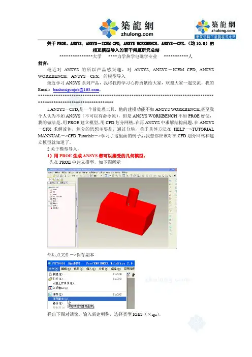
2.关于模型导入,1)用PROE生成ANSYS都可以接受的几何模型,先在PROE中建立模型,如下图所示然后点文件->保存副本弹出下图对话筐,输入新建明称,选择类型IGES(×igs),关闭PROE,记住文件所在文件夹,2)PROE的模型导入ANSYS ICEM CFD,打开ANSYS ICEM CFD指向你刚才生成的文件,然后模型就出现了,2)ANSYS中导入PROE模型3)ANSYS模型导入到ANSYS CFX中,在ANSYS的命令流筐中输入:这时在你的的ANSYS的工作目录下生成了一个banhuaiguo.cdb文件打开ANSYS CFX的前出理界面:最终结果:4)CFD模型导入cfx,打开ANSYSCFX5)CFX模型导入ANSYS,结论:ANSYS1.该方法在PROE野火版ANSYS系列产品10.0中通过测试,2.本人不怎么谦虚,因此有点小小的成绩愿意和大家共享!3.希望斑竹加点分!*******************************待续*******************************。
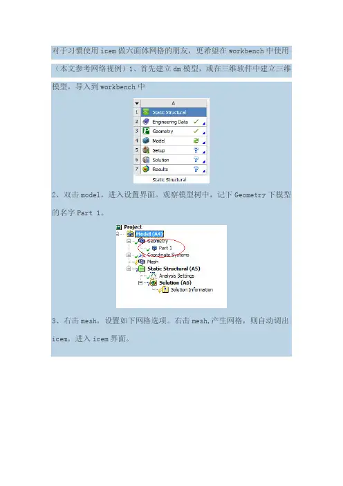
对于习惯使用icem做六面体网格的朋友,更希望在workbench中使用(本文参考网络视例)1、首先建立dm模型,或在三维软件中建立三维模型,导入到workbench中
2、双击model,进入设置界面。
观察模型树中,记下Geometry下模型的名字Part 1。
3、右击mesh,设置如下网格选项。
右击mesh,产生网格,则自动调出icem,进入icem界面。
4、进入icem中,系统自动分块,而这个分块是我们不想要的,因此删除块,重新分块,生产新块时,注意手动选择part名称,保证与2中名字一致。
(part 1,这里是part_1_1_1)
5、icem中划分网格,结果如下
6、产生结构网格,File-Mesh-From....,保存网格,点击yes
7、进行简单的设置,简单的做了个计算,如图所示:。
ANSYS经典界⾯的有限元模型导⼊Workbench,并进⾏其他分
析
将Ansys经典模式中的模型导⼊到Ansys Workbench | 坐倚北风
1.ANSYS画好⽹格
Main Menu - Preprocessor - Archive Model - Write,输出cdb⽂件
2. Woerbench
1. 进⼊Ansys Workbench,在ToolBox中双击Finite Element Modeler将其加⼊到⼯程
2. 在Model上右击,选择Add Input Mesh,将⽣成的.CDB⽂件导⼊
3. 双击Model进⼊Ansys Workbench⼏何模型编辑界⾯,可以在左侧看到所导⼊的有限元模型的详细信息
4. 在Geometry Synthesis下的Skin Detection Tool上右击,选择Create skin components。
5. 当⽣成完模型的表⾯曲⾯后,在Geometry Synthesis上右击,选择Insert - Initial Geometry,即可⽣成有限元模型
6. 在Model上右击,选择Updata,更新⼏何模型(有对号则更新成功)
3.模态分析
1.在Analysis Systems中将modal加⼊到⼯程
2.左键按住Finite Element Modeler的Model,拖到Modal模块的Model
3.双击Modal模块的model,进⼊分析。
Proe中建立的模型导入Ansys中分析的方法发信人: Zengxiaodong (小Z), 信区: CAD标题: Proe中建立的模型导入Ansys中分析的方法发信站: 饮水思源(2001年10月08日09:10:33 星期一), 站内信件方法一:在Pro/E中建立好模型后(一般是part),从菜单File_export_model_IGES,输出IGES格式的文件,这种格式是几乎所有CAD软件都可以识别的(当然Autocad除外,因为它根本就不能称作CAD软件),注意文件最好存放在名字无空格的目录中,否则在Ansys中不能识别My documents和Mydocuments的区别,会出现明明文件存在却告知文件不存在的错误!好了,现在就可以启动Ansys了,从菜单File_import_IGES,选择刚才形成的文件就可以输入模型了。
以上是对于Pro/E2000i2而言的,对于Pro/E2001,已经没有export了,不过可以在菜单F ile_save a copy中选择IGES类型存盘,其他就同上,不必细说了。
在Ansys中输入模型时,可能出现模型断裂的结果,可以对"defeature(毁容)、合并重合的关键点、产生实体、删除小面积"等选项进行改变,反复试验直到输入满意为止,其他内容请各位参考有关资料。
另外说一句,这一方法也可以用在将UGII的模型传到Ansys中,在UG17中很简单,但是在UG16中,必须安装IGES的转换模块,不过仅仅这样仍然不能运行,提示缺少一个dll文件,应将。
\UGII\目录中的一个文件edsps110.dll_old更名为edsps110.dll即可。
方法二:首先,安装Ansys时,必须安装了ANSYS Connection For Pro/ENGINEER模块(代号82 。
在"开始_程序_Ansys 5.6_ANS_ADMIN Utility"中,选择configuration options,选onfigure connection for Pro/E,输入模块类型,图形类型、工作空间大小等,再?Pro/E的安装路径,完成"连接"安装,此时将在Pro/E的相关文件夹中产生一个protk.文件。
AnsysWorkbench自定义和系统材料的添加
Ansys Workbench自定义和系统材料的添加
(1、自定义材料为45号钢,其参数为密度7890 kg/m^-3,杨氏模量为2.09*10^11,泊松比为0.269;2、系统自带材料添加)
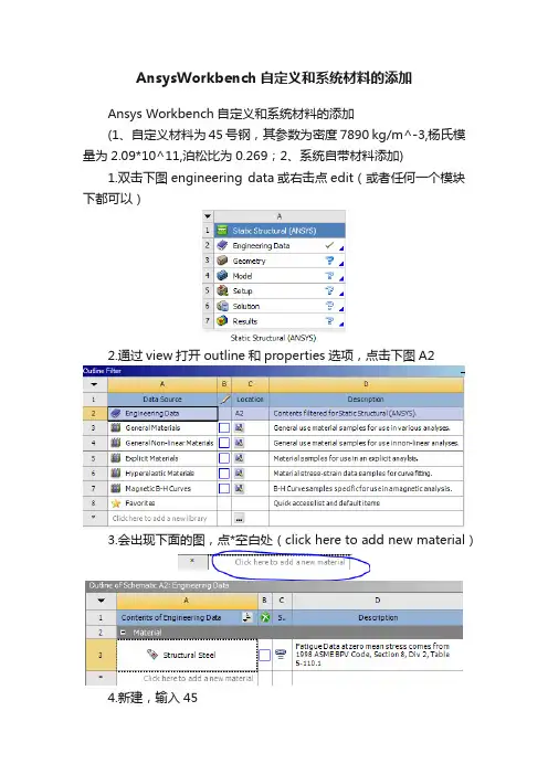
1.双击下图engineering data或右击点edit(或者任何一个模块下都可以)
2.通过view打开outline和properties选项,点击下图A2
3.会出现下面的图,点*空白处(click here to add new material)
4.新建,输入45
5.左键双击击toolbox内的density(密度)和Isotropic Elasticity (各向同性弹性)
6.出现下图
7.输入值密度、弹性模量、泊松比
8.左键单击A3
9.出现下图
10.左键单击点A5后面的出现
11.左键单击下图A2会看到Concrete被添加了进来。
12.左键单击下图的
13.导入几何体或绘制几何体,然后对图1中的model左键双击或右键单击选edit 在新的窗口中展开model-geometry左键单击几何体出现details.
14.左键单击上图中的Material下的Assignment入下图
15.选中45或者Concrete(45为自定义材料/Concrete为系统材料添加)
设置完成。
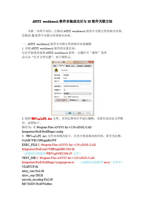
ANSYS workbench软件安装成功后与3D软件关联方法关联一共两个动作:①修改ANSYS workbench软件中关联文件的相关内容;②修改3D软件中关联文件的相关内容。
一、ANSYS workbench软件中关联文件的相关内容编辑1.寻找ANSYS workbench软件的安装目录:①在开始菜单找到ANSYS workbench软件,右键打开“属性”菜单②点击“打开文件位置”,如下图所示:2.找到WBPlugInPE.dat文件,并用记事本打开进行编辑,安装目录决定文件路径。
此例如下。
路径为:C:\Program Files\ANSYS Inc\v120\AISOL\CADIntegration\ProE\ProEPages\config3. WBPlugInPE.dat文件内容修改如下,红色字体是修改的内容,括号为注释:NAME WB120PluginProWFEXEC_FILE C:\Program Files\ANSYS Inc\v120\AISOL\CADIntegration\ProE\intel\WBPlugInPECOM.dll(此路径目的找到WBPlugInPECOM.dll文件)TEXT_DIR C:\Program Files\ANSYS Inc\v120\AISOL\CADIntegration\ProE\ProEPages\Language\en-us(此路径目的找到“en-us”文件夹)STARTUP dlldelay_start FALSEallow_stop TRUEunicode_encoding FALSEREVISION ProEWildfireENDname ac4pro120dllexec_path C:\Program Files\ANSYS Inc\v120\ansys\ac4\bin\pro\intel\ac4pro.exe (此路径目的找到ac4pro.exe文件)text_path C:\Program Files\ANSYS Inc\v120\ANSYS\ac4\data\pro\text(此路径目的找到“text”文件夹)STARTUP dlldelay_start FALSEallow_stop TRUEunicode_encoding FALSErevision 24.0end二、3D软件中关联文件的相关内容1.查找3D软件的安装目录,方法同上。
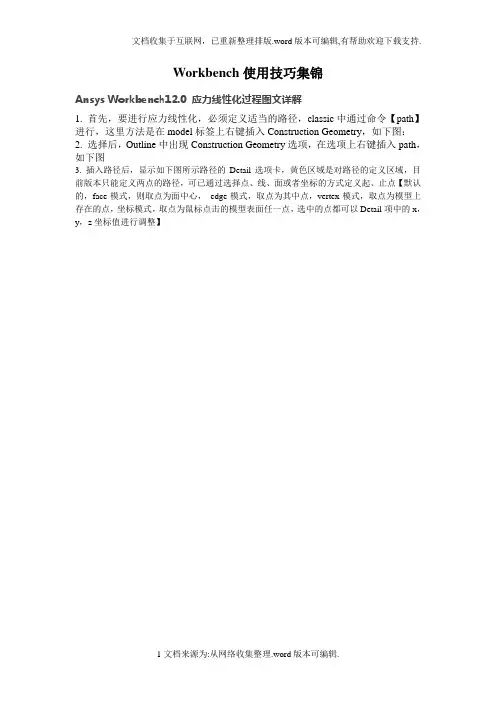
Workbench使用技巧集锦Ansys Workbench12.0 应力线性化过程图文详解1. 首先,要进行应力线性化,必须定义适当的路径,classic中通过命令【path】进行,这里方法是在model标签上右键插入Construction Geometry,如下图:2. 选择后,Outline中出现Construction Geometry选项,在选项上右键插入path,如下图3. 插入路径后,显示如下图所示路径的Detail选项卡,黄色区域是对路径的定义区域,目前版本只能定义两点的路径,可已通过选择点、线、面或者坐标的方式定义起、止点【默认的,face模式,则取点为面中心,edge模式,取点为其中点,vertex模式,取点为模型上存在的点,坐标模式,取点为鼠标点击的模型表面任一点,选中的点都可以Detail项中的x,y,z坐标值进行调整】4. 定义好的路径如下图所示5. 定义好路径后,在标签【Solution 】上右键插入应力线性化选项,或者点中【Solution 】后,在快捷栏选择一种应力线性化,效果是一样的,如下图所示6. 插入应力线性化选项后,出现如下图所示的Detail 选项卡,黄色为预选的路径 选择方式按钮 这里定义路径参照的坐标系,路径取样点数信息选择参与线性化的实体选择应力线性化类型,其实就是重新定义线性化结果时间选项,多载荷步求解使用线性化参照的坐标系,可以选择自己定义的坐标系通过subtype选择的应力类型都会出现在这里,可以看到,这些结果都是可以参数化的,也就是说,可以继续进行基于线性化应力结果的优化定义好的路径会在这里显示,选择一个作为当前线性化路径应力线性化选项,做过的朋友都明白,不详细说了7. 线性化的结果示例。
查看最大最小值坐标先点击outline下的solution以上的图标(如选择Analysis Settings),这时你会发现在菜单Units下的图标Coordinate图标激活,点击之,再按住CTRL,左击Outline下你要的结果云图,鼠标在应力云图上移动,会出现坐标,至于准不准确,研究完了告诉我.......用commmandsnsort,..*get,..nx(..)ny(..)nz(..)在后处理上WB比Classic跟为简单明了,但所能进行的后处理极为有限。
PRO/E与ANSYS的连接接口设置——如何将Pro/E模型导入ANSYS进行有限元分析ANSYS在默认的情况下是不能将Pro/E中的“.prt”文件直接进行转换的,必须通过相应的配置设置来激活该数据连接接口使其正常工作。
下面就是进行配置的整个过程(Pro/E4.0与ANSYS10.0):1. 点击开始菜单里的所有程序中的ANSYS10.0]\[Utilities]\[ANS_ADMIN],出现ANS_ADMIN 10.0对话框,如图所示,选择[Configuration options]\[OK],出现Configuration options配置对话框。
2. 在接下来的对话框中分别做如下选择:[Configure Connection for Pro/E]\[OK];[ANSYS Multiphysics &win32]\[OK];如图所示。
配置成功后会出现连接成功的对话框,如图所示。
3. 再进行如下设置:Pro/Engineer installation path:输入Pro/E的安装路径,如,C:\Program Files\proeWildfire4.0,Language used with Pro/Engineer:中文版就填chinese_cn,OK;然后会出现如图所示的配置成功对话框,提示在Pro/E目录下成功建立了一个“prokt.dat”文件,点击确定即完成配置。
4. 修改“protk.dat”文件。
在Pro/E安装目录文件中找到“protk.dat”文件,路径是“C:\Program Files\proeWildfire 4.0\i486_nt\text\chinese_cn\protk.dat”。
用记事本打开“protk.dat”,然后在“allow_stop TRUE”和“revision 24.0”之间加上“unicode_encoding FALSE”,如图6所示,最后保存并关闭。
Workbench使用说明书一、Windownew window(新窗口)open perspective(打开视图)show view(显示视图)import perspectives(导入视图)export perspectives(导出视图)customize perspective(自定义视图)save perspective as(保存视图为)reset perspective(复位视图)close perspective(关闭视图)navigation(导航)preferences(偏好)二、界面其中默认拥有advanced device development(先进设备开发区) basic device development(基本设备开发区)device debug(设备调试)三个界面,选择other…出现下图:code coverage analyzer(代码覆盖率分析)cvs repository exploring (CVS的探索)debug(调试)memory analyzer(内存分析器)performance profiler(性能分析器) remote system explorer(远程系统管理) resource(资源)system viewer(系统浏览器)team synchronizing(团队同步)三、窗口build console(建立控制台)error log(错误日志)file navigator(文件浏览器)outline(概述)problems(问题)progress(进步)project explorer(工程浏览器) properties(性能)remote systems(远程系统)tasks(任务)terminal(终端)四、工具条Windows ——Customize Perspective(定制透视图/观点)Tool bar visibility(工具条可见性)file(文件)analysis actions(分析活动)opc-ae client(OPC AE客户端)opc-da client(OPC DA客户端)debug update modes(调试更新模式)update make projects(更新项目)c/c++ element creation(C / C++元素的创作) launch(发射)search(搜索)cvs(CVS)team(团队)window working set(窗口工作集)working set manipulation(工作集的操作) editor presentation(编辑演示文稿) navigate(导航)Menu vidibility(菜单栏可见)file(文件)edit(编辑)source(来源)refactor(重构)source(来源)refactor(重构)navigate(导航)search(搜索)project(项目)target(目标)analyze(分析)run(运行)cvs(CVS)design(设计)window(窗口)help(帮助)command group availability(命令组可用性)Shortcuts(快捷键)五、FileFile(文件)convert line delimiters to (转换行分隔符到) switch workspace(切换工作空间)restart(重启)properties(性能)六、Sourcetoggle comment(切换注释)add block comment(增加注释块)remove block comment(移除注释块)correct indentation(正确缩进)format(格式化)add include(添加include)sort lines(线性分类)implement method(实施方法)generate getters and setters(生成 getters and setters)七、Projectopen project(打开项目)project references(引用项目)close project(关闭项目)open development shell(开放发展的壳)build all(建立所有)build project(建设项目)run last build(运行最新的build)build containing folder/target(建立包含文件夹/目标) compile file(编译文件)clean(清除)build options(编译选项)properties(性能)八、Runrun last launched(运行上次启动)debug last launched(调试上次启动)run history(运行历史)run as(运行)run configurations(运行配置)debug history(调试的历史)debug as(调试)debug configurations(调试配置)middleware clients(中间件的客户)script(脚本)。
前面几篇文章已经提到过,ANSYS WORKCENCH主要是为不大懂ANSYS命令和编程的工程师服务的,而经典界面则适用于初学者和研究人员。
初学者和研究人员是完全不同的两个层次,为什么ANSYS经典界面却同时适合二者呢?实际上,学好ANSYS,关键并非是操作界面,而是要学好有限元。
如果初学者直接从WORKBENCH来学习ANSYS,那么对于有限元就毫无收获,可以说一头雾水。
而如果从经典界面进去,因为涉及到很多与有限元概念密切相关的操作,对于理解有限元很有好处。
只是学到一定程度以后,需要转移到WORKBENCH中进行三维零件的分析和装配体的分析。
而当我们用到一定程度以后,发现WOKRBENCH虽然操作方便,但是的确不容易操作底层。
前面的文章已经说明了如何联合二者进行仿真,以充分使用WOKRNBEHCN对于建模的方便性以及经典界面对于底层的操控性。
这里再举一个例子,说明如何用WOKRBENCH进行建模,而后在经典界面中进行后处理,目的是为研究人员提供参考。
一个两边固定的梁,上面受到分布载荷作用如下图。
该分布载荷随时间而改变,其载荷的时间历程如下曲线,从0-1秒,载荷增加到1Mpa,而后保持1秒钟,接着减小到0Mpa,终止时间是3秒。
为了便于控制,这里对每个载荷步均采用自定义载荷子步的方式,划分为10个载荷子步,见下面的细节视图。
然后进行瞬态隐式动力学分析,得到该梁的位移和von mises应力。
我们现在要知道该梁上某一个应力最大的点,其应力是如何随时间而改变的。
这个任务使用WOKRBENCH很难达到,但是用经典界面则轻而易举,因此我们决定使用经典界面进行后处理。
要使用经典界面后处理,只需要把WORKBENCH中生成的结果文件导入到经典界面中即可。
首先找到WORKBENCH中生成的结果文件如下图所示的路径。
该文件叫file.rst,为了方便,把file.rst拷贝到D盘的根目录下,然后启动ANSYS APDL,即经典界面。
参见Ansys help “FE Modeler”部分“Link FE Modeler to Other Workbench Systems”参见simwwe论坛实例赏析部分WB与APDl模型相互导入可通过FE MODELER作为中介来实现,从FE MODELER可以读入、也可以写出.CDB文件,APDl可以写出也可以读入.CDB文件,FE MODELER还可以写出.inp文件供APDL或者ABAQUS使用将WB的模型导入Classicthe Write Solver File button can be used in conjunction with the Target System field in the toolbar to write out FE Modeler data to solver input files, through the use of Templates. Templates are provided to allow you to easily generate a customized Mechanical APDL, ABAQUS, STL, or NASTRAN input deck. There is also an option to create a custom Template. To write a solver file, select Generate Data in the Tree Outline, select the Target System template that you want to use, and click on the Write Solver File button in the toolbar. The following options are available from the Target System drop-down list:∙The Mechanical APDL application∙ABAQUS∙NASTRAN∙STL∙TemplateSee the FE Modeler Options section for information on how to change the path to a target system template.Workbench 中FE MODELER的作用(来自帮助文件)The Role of FE Modeler in ANSYS WorkbenchFE Modeler works with the standard finite element representation used inside ANSYS Workbench. FE Modeler supports robust data transfer from NASTRAN, ABAQUS, STL, and other ANSYS Workbench applications into the Mechanical and Mechanical APDL applications.Use FE Modeler to:∙Import a finite element (FE) model from a NASTRAN bulk data file or ABAQUS Input file. (导入从第三方软件产生的有限元模型)∙Import a finite element (FE) model from an STL input file.∙Import FE information from the Mechanical application.∙Import FE information from Advanced Meshing. This capability is based upon specific licensing requirements. Please see the FEModeler Licensing section shown below. (导入网格文件)∙Import archived Mechanical APDL data created using the CDWRITE command. This command writes a file with the default extension .cdb.(导入由经典APDL生成的模型,导入的模型只包含有限元模型,而不包括点、线、面、体等几何模型,需要另外的操作进一步生成)∙Navigate and visualize the data contained in the model.∙Generate a geometry from an FE Model using the Geometry Synthesis feature. (由有限元模型生成几何模型)∙Given an ANSYS Mesh Morpher license, parameterize and transform a generated geometry.∙Create named components based on element selections.(根据element selections 创建组件)∙Generate a Mechanical APDL, NASTRAN, ABAQUS, or STL input deck for downstream analysis. (生成APDL或者第三方软件所需的有限元模型)∙Import a Fluent or CFX Mesh file. (导入FLUENT或者CFX的网格文件)Workbench Advanced MeshingIf you have Workbench as well as ANSYS ICEM CFD installed, you can take a mesh from the ICEM CFD Meshing application into FE Modeler.FE Modeler User InterfaceFE MODELER 写出.INP文件(针对APDL或者ABAQUS、NASTRAN 等格式)FE MODELER由有限元模型生成几何模型的方法由FE MODELER 从有限元模型导出几何模型文件FE MODELER中查看单元类型FE MODELER中查看接触对FE MODELER中查看材料、实常数、组件、梁单元、约束、集中力、面力、约束方程等Basic FE Modeler WorkflowThe following steps summarize the typical workflow when using FE Modeler. Subsequent sections describe additional tasks for exploring the data and for adding named components to the FE model.e Workbench to Open or Create an FE Modeler System.e Workbench to Link FE Modeler to Other Workbench Systems.e the FE Modeler Editor to review the Import Summary report.During import, FE Modeler dynamically builds a report summarizing the information obtained from the meshes that were imported. The report also includes a list of issues raised during the import process. Carefully review these issues to determine their effect on the FE model.e the toolbar to print the report or export the document as anHTML file.5.Export the model using the Target System drop-down list on thetoolbar and select one of the following templates:∙Mechanical APDL - Default∙ABAQUS∙NASTRAN∙STL∙Template - Customizable option for one of the above output selections.6.(Optional) Create a geometry from the finite element mesh using theGeometry Synthesis feature. This feature enables you to use the model for further analyses in Workbench or to perform parametric studies.e the toolbar to print the preview or export the data in the formof the target system’s commands to an .inp file.Note: Because it is not unusual to encounter large gaps in node and element numbering in finite element models, Generated Data,by default, compresses any such gaps when exporting to theMechanical APDL application. You can disable the option thatchanges the ID's of all of nodes and elements that are sentto the target system from FE Modeler through the Tools>Options feature. However, sending large entity numbers suchas node or element ID's may not be memory efficient in theMechanical APDL application.FE MODELER导出到APDL默认单元类型Mechanical APDL as the Target SystemWhen Mechanical APDL is used as the Target System the following entities, if present, are written out as Mechanical APDL commands from FE Modeler.Note: O nly structural element types aresupported.Exported Mechanical APDL FE Entity Types have the following specifications.FE MODELER导出到ABAQUS 默认单元类型ABAQUS as the Target SystemWhen ABAQUS is used as the Target System the following entities, if present, are written out as ABAQUS commands from FE Modeler.NoteOnly structural element types are supported.:Exported ABAQUS FE Entity Types have the following specifications.FE MODELER导出到自定义模板自定义单元类型Template asthe Target SystemWhen Template is used as the Target System, you are prompted to open a customized template that you have created. A customized template allows you to control the order in which FE data is written out. In addition you can also intersperse commands with a template that are not supported by FE Modeler to perform advanced modeling or provide analysis controls.Note: STL meshes are not supported by template target systems in 12.x.Shown below are the commands contained in the Workbench provided default template for each of the supported target systems that you will use as the basis for a customize template. In addition, samples of the template are provided.Note: Not all entities imported into FE Modeler can be exported to all of the available systems.自定义单元类型实例Sample TemplatesThe Mechanical APDL application as the target system.<WBTEMPLATE>!HEADING! File created at @TimeStamp@!! This template extracts the FEModeler mesh in a format! compatible with the Mechanical APDL application input!@MeshNodes@!@MeshElements@!@ElelemntType@!@MaterialProperties@!@Components@!@InterfaceRegions@!@Loads@!@BoundaryConditions@!@PhysicalProperties@!NASTRAN as the target system.<WBTEMPLATE TARGET=NASTRAN>$$$ File created at @TimeStamp@$$ This template extracts the FEModeler mesh in a format$ compatible with NASTRAN input.$BEGIN BULK$$ MATERIAL PROPERTIES$@MaterialProperties@$$ MESH NODES$@MeshNodes@$$ MESH ELEMENTS$@MeshElements@$$ENDDATAABAQUS as the target system.<WBTEMPLATE TARGET=ABAQUS>*HEADING** File created at @TimeStamp@**** This template extracts the FEModeler mesh in a format** compatible with ABAQUS input**@MeshNodes@**@MeshElements@**@MaterialProperties@**Sample templates are provided to perform a large deflection analysis using the Mechanical APDL application, NASTRAN or ABAQUS.将WB的模型导入Classic四种方法the Write Solver File button can be used in conjunction with the Target System field in the toolbar to write out FE Modeler data to solver input files, through the use of Templates. Templates are provided to allow you to easily generate a customized Mechanical APDL, ABAQUS, STL, or NASTRAN input deck. There is also an option to create a custom Template. To write a solver file, select Generate Data in the Tree Outline, select the Target System template that you want to use, and click on the Write Solver Filebutton in the toolbar. The following options are available from the Target System drop-down list:∙The Mechanical APDL application∙ABAQUS∙NASTRAN∙STL∙TemplateSee the FE Modeler Options section for information on how to change the path to a target system template.近来有不少人发贴询问这个问题。