ADAMS+AMESIM+SIMULINK操作说明
- 格式:doc
- 大小:1.19 MB
- 文档页数:6
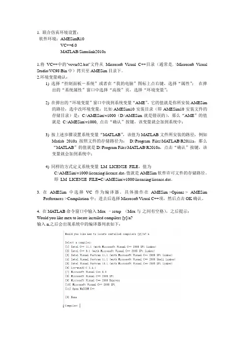
1. 联合仿真环境设置:软件环境:AMESimR10VC++6.0MA TLAB/Simulink2010a1.将VC++中的"vcvar32.bat"文件从Microsoft Visual C++目录(通常是. \Microsoft Visual Studio\VC98\Bin中)拷贝至AMESim目录下。
2.环境变量确认:1) 选择“控制面板-系统”或者在“我的电脑”图标上点右键,选择“属性”;在弹出的“系统属性”窗口中选择“高级”页,选择“环境变量”;2) 在弹出的“环境变量”窗口中找到系统变量“AME”,它的值就是你所安装AMESim的路径,选中改环境变量;比如AMESim10安装目录(即AMESim10安装文件的存储目录)是:C:\AMESim\v1000(D:\AMESim就是错误的),那么“AME”的值就是C:\AMESim\v1000, 点击“确认”按键,该变量就会加到系统中;3) 按上述步骤设置系统变量“MATLAB”,该值为MA TLAB文件所安装的路径,例如Matlab 2010a按照文件的存储路径为:D:\Program Files\MATLAB\R2011a,那么“MA TLAB”的值就是D:\Program Files\MATLAB\R2010a,点击“确认”按键,该变量就会加到系统中;4) 同样的方式定义系统变量LM_LICENSE_FILE,值为C:\AMESim\v1000\licensing\license.dat,值就是AMESim软件许可文件的存储路径。
即LM_LICENSE_FILE=C:\AMESim\v1000\licensing\license.dat。
3. 在AMESim中选择VC作为编译器。
具体操作在AMESim->Opions-> AMESimPreferences->Compilation中;进去后选择Microsoft Visual C++项,然后点击OK确认。
Adams和AMESim的联合仿真前言:本人并不是Adams和AMESim的高手,接触AMESim的时间很短,但是需要做Adams和AMEsim的联合仿真,这里分享一下我探索联合仿真的经验。
目录如下:一、仿真前需要做的准备。
1、软件的安装2、环境变量的设置二、一个具体的联合仿真例子。
(这里只介绍Adams主控的仿真)***********************************************************一、仿真前的准备1、软件的安装软件的版本对联合仿真有重要影响,这里只介绍我自己安装软件的情况。
我的系统是win7 32位,安装的软件是Adams2013、LMS b AMESim Rev 13、Visual Studio 2010。
Adams2013和AMESim Rev 13网上有很多下载资源和安装教程。
这里我只强调一下Visual Studio 2010。
也就是可以建立两个仿真软件联系的Visual C++程序。
Visual C++和VisualStudio等之间的关系大家可以自己在网上查,其实都包含有C++语言。
网上有些教程是用VC++6.0来建立两者之间的关系,但是我安装了VC++6.0的各种版本(企业版,中文版,英文版)都没有成功建立仿真,后来安装了完整的Visual Studio 2010就可以了,但是Visual Studio 2010有些大,我下载的是1.75G。
另外就是安装顺序,最好先安装VC++或者VS(我是最后安装的Visual Studio 2010,先安装的说法我这里并没有证实)。
下面是我的软件的安装位置,安装目录没有中文D:\zy\ADAMSD:\AMESimD:\Program Files\Microsoft Visual Studio 10.0在最后安装好Visual Studio 10后把D:\ProgramFiles\Microsoft Visual Studio 10.0\VC\bin下的nmake和vcvars32文件拷贝到AMESim的安装目录下D:\AMESim\v1300。
AMESim与ADAMS联合仿真操作说明摘要:物理系统可能由各种元件组成,例如气动的,机械的,液压的,电子的以及控制系统等,所有的元件协同工作。
多学科领域系统和复杂多体系统之间的相互作用很难在单一的软件平台中来仿真。
解决的方案就是通过AMESim和专用的多体动力学软件ADAMS之间的接口,使得两者在仿真中协同工作。
本文结合天线的简单实例介绍AMESim与ADAMS联合仿真的操作过程。
关键词:AMESim ADAMS 联合仿真1.引言AMESim(Advanced Modeling Environment for Simulation of engineering systems)软件是由法国IMAGINE公司于1995年推出的多学科复杂领域系统工程高级建模和仿真平台,该软件不要求用户具备完备的仿真专业知识,采用面向系统原理图建模的方法,便于工程技术人员掌握和使用。
机构动力学分析软件ADAMS (automatic dynamic of mechanical system)集建模、求解和可视化技术于一体,能有效分析和比较多种参数方案。
运用AMESim与ADAMS的联合仿真,可以有效的对设备的动态过程进行分析,根据交互分析产生的结果来评价设备的性能,为了更加真实的符合实际情况,理论分析用来完成检验产生的数值结果。
这种虚拟产品开发方法与得出的结论将对设计人员提供一定帮助。
通过AMESim/ADAMS之间的接口,有两种方式实现联合仿真:(1)将模型从一个平台中输入到另一个平台中,采用单一的积分器进行计算。
(2)各个平台分别利用自己的积分器计算自己的模型,通过预先统一的通讯间隔进行信息交换。
2.软件环境要求首先AMESim软件需要4.2级以上版本; ADAMS需要2003级以上版本(含A/Control模块)。
其次必须要有Microsoft Visual C++ 编译器。
如果需要从ADAMS环境中使用接口,那么还强烈推荐Fortran编译器,这样可以将AMESim的模型编译成为ADAMS的子函数(Subroutine)。
联合仿真可以充分利用各仿真软件的优点,从而简化建模实现快速仿真。
这里首先讲下如何实现联合仿真,工欲善其事,必先利其器。
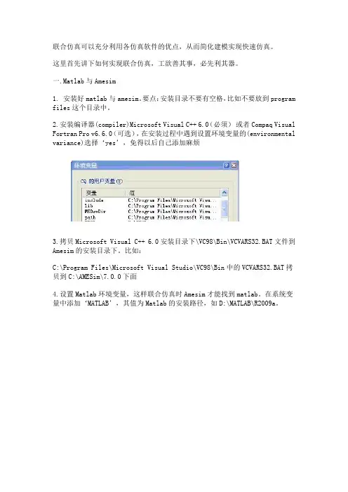
一.Matlab与Amesim1. 安装好matlab与amesim。
要点:安装目录不要有空格,比如不要放到program files这个目录中。
2.安装编译器(compiler)Microsoft Visual C++ 6.0(必须)或者Compaq Visual Fortran Pro v6.6.0(可选),在安装过程中遇到设置环境变量的(environmental variance)选择‘yes’,免得以后自己添加麻烦3.拷贝Microsoft Visual C++ 6.0安装目录下\VC98\Bin\VCVARS32.BAT文件到Amesim的安装目录下。
比如:C:\Program Files\Microsoft Visual Studio\VC98\Bin中的VCVARS32.BAT拷贝到C:\AMESim\7.0.0下面4.设置Matlab环境变量,这样联合仿真时Amesim才能找到matlab。
在系统变量中添加‘MATLAB’,其值为Matlab的安装路径,如D:\MATLAB\R2009a。
5.在matlab中设置编译器(如下图)。
在matlab命令行里输入mex -setup,选择编译器Microsoft Visual C++6.0 ,最后选Y确定。
6. 在Amesim里选择编译器。
打开Amesim--tools--options--Amesim preferences选择Microsoft Visual C++7.在Matlab 的目录列表里加上AMESim与Matlab 接口文件所在的目录%AME%\matlab\amesim,其中%AME%是AMESim的安装目录,如果安装在C:\AMEsim ,则就加上C:\AMEsim\matlab\amesim。
(有的版本这个目录可能是安装目录\******ing\matlab\amesim)8.在matlab中set path中继续添加路径:%AME%\7.0.0\interface\simulink以及%AME%\7.0.0\interface\sl2ame9. 完成,实现amesim to simulink 和simulink to amesim 的联合仿真。
系统仿真AMESim软件使用说明目录1.AMESim是什么?2.AMESim 建模步骤?3.AMESim接口4.AMESim标准库5.AMESim软件包6.AMESim参数和变量观察7.AMESim建模(调用已有模型,讲解各元件及相互间联系)1.AMESim是什么?AMESim表示工程系统仿真高级建模环境(Advanced Modeling Environment for performing Simulations of engineering systems).基于直接图形接口,在整个仿真过程中草图系统可以显示在环境中。
AMESim 使用图标符号代表各种系统的元件,这些图标符号要么是国际标准组织(如工程领域的ISO为液压元部件)确定的标准符号、控制系统确定的方块图符号,或者当不存在这样的标准符号时可以为该系统给出一个容易接受的非标准图形特征。
Figure 1.1: AMESim中使用符号(标准液压,机械和控制符号表达的一个工程系统)Figure 1.2: 汽车制动系统的符号(非标准图形特征)2.如何使用AMESim?可按如步骤进行系统建模仿真:• sketch mode (草图模式)----从不同的应用库中选取现存的图形• submodel mode (子模型模式)----为每个图形选择子模型(即给定合适的数学模型假设)• parameter mode (参数设置模式)----每个图形模型设置特定的参数• simulation mode (仿真模式)----运行仿真并分析仿真结果大多数自动化系统都可按上述步骤执行,在每一步都可以看到系统草图。
3.接口与脚本you have the possibility of interfacing with Matlab/Simulink to test the Electronic Control Unit (ECU) of the complete gearbox and have the complete simulation platform for the conception of every kind of gearboxes3.1接口3.2 脚本4.标准库标准库提供了控制和机械图标,子模型允许你完成大量工程系统的动态仿真。
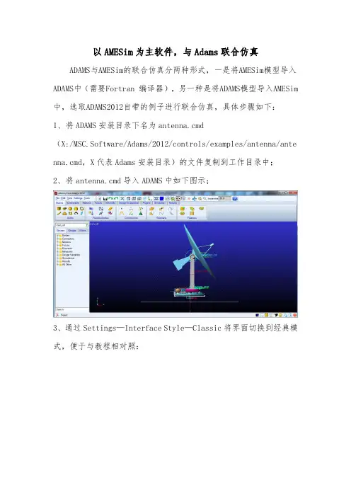
以AMESim为主软件,与Adams联合仿真ADAMS与AMESim的联合仿真分两种形式,一是将AMESim模型导入ADAMS中(需要Fortran 编译器),另一种是将ADAMS模型导入AMESim中,选取ADAMS2012自带的例子进行联合仿真,具体步骤如下:1、将ADAMS安装目录下名为antenna.cmd(X:/MSC.Software/Adams/2012/controls/examples/antenna/anten na.cmd,X代表Adams安装目录)的文件复制到工作目录中;2、将antenna.cmd导入ADAMS中如下图示;3、通过Settings—Interface Style—Classic将界面切换到经典模式,便于与教程相对照:图示:5、Build—System Elements—New,创建状态变量azimuth_position,control_torque,elevation_position,rotor_velocity;6、Build—System Elements—Modify修改变量7、通过Date Elements—Plant—Plant Input/Plant Output建立输入输出变量,并与状态变量连接起来8、右击azimuth—actuator将力与输入变量连接起来8、通过Controls—Plant Export,导出模型,完成相关设置后点OK;9、zuoye文件夹中生成以下文件:10、在AMESim中建立以下模型,如下图示通过Modeling—Interface block—Import Adams model,选择工作目录中刚刚生成的adams2amesim .inf文件完成如下图示的相关设置11、最终建立的AMESim模型如下图示:12、进行模拟仿真13、在Amesim中查看模拟结果14、在Adams/PostProcessor 中查看模拟结果。
AMESim与ADAMS联合仿真1、安装软件最好的安装顺序:VS , Adams,Amesim安装路径不要有中文和空格及特殊字符2、环境变量设置AME_ADAMS_HOME,指向Adams安装目录,如:D:\MSC.Software\MD_Adams\R3ADAMS_CONTROLS_WTIME=203、安装完成后,确认在AMESim安装目录下(如:AMESim/v1300)已包含如下文件:nmake.exevcvars32.bat如果没有,从VS安装目录拷贝过来(C:\Program Files (x86)\Microsoft Visual Studio 11.0\VC\bin)。
4、将adams库加入到AMESim路径中:五、如果提示MSSDK问题,安装GRMSDKX_EN_DVD.iso。
也就是安装Windows SDK7.1如果安装时报错,可按照方法:卸载比Microsoft Visual C++ 2010 x86 Redistributable - 10.0.30319 以及Microsoft Visual C++ 2010 x64 Redistributable - 10.0.30319更高的版本。
如果还出错,在安装时不要选择安装VC-Compiler,其它选项默认即可。
如果卸载了上面的两个组件,则需要安装VBVCRedist中的两个补丁,只需要选择两个卸载的补丁即可。
六、如果提示AsUtility_imp.lib的link错误,在C盘中搜索,找到该文件,再放到AMESim 模型所在工作目录。
(一般不需要此项。
)七、64位操作系统中:AMESim中选择Microsoft Visual C++编译器,Subplatform type选择win64。
如下图八、接口类型为ADAMS还是AdamsCosim,决定于是用离散耦合,还是连续的。
Adams or AdamsCosim depending whether you want to run discrete coupling or continuous export选择AdamsCosim则adams中应该为Discrete。
Simulink与AMSIM联合仿真的方法虽然随着新材料、电机技术、控制学和先进制造技术等的发展,出现了用以取代目前所依赖的功率液压传动的功率电传技术,但是在现阶段,液压伺服作动系统仍然占据航空作动系统的主导地位。
主要原因是液压伺服作动系统具有其它伺服作动系统无法比拟的优势,具有容易得到大功率输出、高功率/重量比、响应快和低俗特性好的特点。
航空液压作动系统是目前飞机上最成熟的液压作动方式,大多直接采用飞机的中央液压源提供的恒压油,通过(伺服)阀来控制执行机构的双腔流量完成指令动作,精度高、响应快。
航空也要作动系统根据其发展历程一般分为以下四类:液压助力器、电液指令作动器、复合式伺服作动器和直接驱动阀式伺服作动器。
本文将主要对其关键技术进行深入分析,并提出关键技术的解决途径。
1 建模仿真技术由于对航空液压作动系统自身结构比较复杂,对其自身的性能要求比较高,需要满足包括输出载荷、中立位置、额定行程、最大行程、行程余量、额定速度、最大速度、极限载荷、主控阀剪切力、门限、位置精度和滞环等的静态特性,满足包括频率响应和阶跃响应的动态特性,以及稳定性和阻抗特性要求。
银次,在研制航空液压作动系统的过程中,对其进行建模仿真非常重要。
通过仿真,可以对所设计的作动器性能有全面的了解,便于改进和完善设计。
传统的建模仿真分析手短一般采用数学推到加Simulink仿真的方式进行。
Simulink是美国Match Works公司开发的MA TLAB软件的可视化仿真环境,具有丰富的线性/非线性、连续/离散等控制系统仿真功能模块,具备神经网络、模糊控制等一系列先进的智能控制工具箱,非常适合进行航空液压作动系统的建模与分析,但其前提是基于用户建立的数学模型和其自身提供的结构参数化的功能模块。
而这已无法满足现在对仿真高精度和高准确度的要求。
而且Simulink本身没有专门针对液压流体仿真的工具箱,用户使用时要自己建立模型。
AMESim是法国Imagine公司推出的基于功率键合图的液压/机械系统建模、仿真机动力学分析软件,采用图形化的物理建模方式,具有复杂液压元件结构参数化的功能模块,也同样非常适合进行航空液压作动系统的结构参数化建模与分析,但是他的控制系统仿真功能模块相对较少,不具备神经网络、模糊控制等一系列先进的智能控制工具箱。
AMESim和ADAMS联合仿真实现一种位置控制系统0.预先操作01 在D盘根目录下新建文件夹Model,路径中无空格、无中文字符,模型统一存放处。
1.ADAMS中建模过程1.1启动ADMAS双击桌面图标:或从“开始”中选择启动:1.2进入ADMAS界面。
1.3设置工作目录。
选择菜单栏File\Select Directory,弹出浏览文件夹对话框,选择D:\Model文件夹。
1.4弹出主工具栏。
选择菜单栏\View\Toolbox andToolbars,勾选Tool Settings中Main Toolbar,弹出工具栏,如右图所示。
1.5ADAMS中按F4调出位置/坐标显示。
1.6设置重力加速度。
选择菜单栏\Setting\Gravity,设置重力加速度,此时弹出Error对话框。
选择“Create Moder”,并起名为“Qiu”,点击“OK”再次选择菜单栏\Setting\Gravity,设置重力加速度:勾选Gravity前方框,点击-Y*,如下图示,点击“OK”。
1.7设置单位。
选择菜单栏\Setting\Units,设置单位,此时弹出“UnitsSettings”对话框,点击“MKS”按钮,各单位符号如右图示,点击“OK”。
1.8建立半径10cm的球,放置在点(0,0,0)上。
“右键”点击主工具栏第一排第二个符号-刚体:连杆,弹出扩展工具符号,选择第二排第一个符号-刚体:球,勾选Radius前方框,则此球半径为10.0cm。
1.9建立球与大地之间移动副。
“右键”点击主工具栏第二排第二个符号-连接:旋转副,弹出扩展工具符号,选择第二排第一个符号-连接:移动副。
该移动副属性为2个构件,1个作用点。
鼠标动作顺序为:1.左键点击“ground”一次,选取大地为第一个构件;2.左键点击球体一次,选取球为第二个构件;3.右键在球心位置点击一次,弹出Select对话框,左键双击“PART_2.cm”;4.右键在球心位置点击一次,弹出Select对话框,左键双击“PART_2.cm.Y”。
ADAMS interface® Rev 9 – November 2009Copyright © LMS IMAGINE S.A. 1995-2009AMESim® is the registered trademark of LMS IMAGINE S.A.AMESet® is the registered trademark of LMS IMAGINE S.A.AMERun® is the registered trademark of LMS IMAGINE S.A.AMECustom® is the registered trademark of LMS IMAGINE S.A.LMS b is a registered trademark of LMS International N.V.LMS b Motion is a registered trademark of LMS International N.V.ADAMS® is a registered United States trademark of MSC.Software Corporation.MATLAB and SIMULINK are registered trademarks of the Math Works, Inc.Modelica is a registered trademark of the Modelica Association.UNIX is a registered trademark in the United States and other countries exclusively licensed by X / Open Company Ltd.Windows is the registered trademark of the Microsoft Corporation.All other product names are trademarks or registered trademarks of their respective companies.TABLE OF CONTENTS1. Introduction (1)1.1. Organization of this manual 22. Preliminaries (3)2.1. License requirements 32.2. Compiler requirements 32.2.1. Requirements to import ADAMS model into AMESim 32.2.2. Requirements to export AMESim models into ADAMS 32.3. Versions of ADAMS supported 42.4. Platforms supported 42.5. Setting up the environment 43. Importing AMESim into ADAMS (7)3.1. Preliminary 73.2. Import AMESim models into ADAMS 93.2.1. Preparing an AMESim model for export to ADAMS 93.2.2. Importing the model in ADAMS 114. Importing Adams into AMESim (20)4.1. Introduction 204.2. Preparing an ADAMS model for export to AMESim 224.2.1. Step 1: Check exchanged variables 224.2.2. Step 2: Create the Interface 254.2.3. Step 3: Export the system from ADAMS into AMESim 264.3. Importing the model into AMESim 274.3.1. Step 1: Import file generated by ADAMS 274.3.2. Step 2: Configuration of the interface block 294.3.3. Step 3: Running a simulation 304.4. Analyzing results in both software 325. Co-simulation or full export? (32)6. Tips on using the interface (35)6.1. How to stop a simulation 356.2. How do you execute ADAMS commands before a co-simulation? 367. Advanced use of the interface (36)7.1. How to setup interface with template-based ADAMS products 367.1.1. Using more than one interface 377.2. Advanced configuration of the interface 377.2.1. Configuration file 37Using theAMESim / ADAMS Interface 1. IntroductionThe AMESim ADAMS interface enables you to link an AMESim model with an ADAMS multibody model of a mechanical structure. By coupling motion simulation and system simulation, this interface improves the accuracy of your full system simulation.This interface is useful when hydraulic or pneumatic fluid power systems or other AMESim systems interact with complex mechanical structures.The interface is designed so that you can continue to use many of the AMESim facilities while the model is running in ADAMS. In particular, you can change the parameters of the AMESim model within AMESim in the normal way and monitor the results by creating plots just as if you were producing a regular run.Normally you will have AMESim and ADAMS running simultaneously so that you can use the full facilities of both packages. An illustration of this process follows:When the process is finished, the user can change the AMESim model parameters within AMESim, as well as the ADAMS parameters within ADAMS.1.1. Organization of this manualThis manual describes both the two-way full export interface (using ADAMS or AMESim integrator exclusively for the full system) and the two-way co-simulation interface (where both solvers are used, one of them being called by the other).The main part of the manual deals with the standard interface and section 5 looks at the differences between export and co-simulation.The structure of this manual is the following:•Section 1 is the current section.• Section 2: Preliminaries, describes how you must set your working environment so that you can use the interface.• Section 3:Error! Reference source not found. describes how ADAMS imports the AMESim model.2. Section 4: Importing Adams into AMESim•, uses a simple example to describe how to create an AMESim model and configure it to run in cooperation with ADAMS.•Section 5: This section describes the differences between co-simulation interface and the export facility.• Section 6: Tips on using the interface, gives some advice on efficient use of the interface.• Section 7: Advanced use of the interface and Section 8: Advanced configuration of the interface, are useful for customized use of the interface (advanced users). Sometimes a section of text is only valid for a UNIX or Linux environment, for such text, the following presentation is used:Using UNIX:Description for Unix/Linux based environments.Similarly, sometimes a section of text is only valid for a Windows environment, for such text, the following presentation is used:Using Windows:Description for Windows based environments.We assume that either the reader of this manual is already familiar with using AMESim and ADAMS or an AMESim user and an ADAMS user will collaborate in performing the task.We recommend that new AMESim users at least do the tutorial examples in the AMESim manual before attempting a combined simulation. Similarly, a new ADAMS user should become familiar with using ADAMS before attempting a combined simulation.3. Preliminaries3.1. License requirementsWhen the user is running a coupled simulation from the AMESim environment, an Adams interface license is required in AMESim in combination with a standard AMESim runtime license. On the ADAMS side the module Adams/Controls (A/Controls) is needed.When running simulations from ADAMS the user only needs Adams interface and AMESim runtime licenses, A/Controls is unused.3.2. Compiler requirements3.2.1. Requirements to import ADAMS model into AMESimUsing Unix:You will need an ANSI C compiler.Using Windows:You must have at least Microsoft Visual C/C++ 6.0, .NET 2003, 2005.3.2.2. Requirements to export AMESim models into ADAMS AMESim follows the requirements given for ADAMS 2005Software specifications are:Hardware Vendor OperatingSystem Fortran C/C++Intel andIntel- compatible PCs Windows 2000,Windows XPProfessionalCompaq VisualFortran 6.6BMS Visual C/C++ 6.0 (SP5)orVisual Studio C++.NET 2003c89 11.01.20aC++ 03.27Hewlett Packard HP-UX 11, 11i f90 2.4.13SGI IRIX6.5.14m7.3.1.2m 7.3.1.2mIBM AIX 4.3.3, 5.1*XL Fortran 7.1 Visual Age C/C++ 5.0.2Sun Microsystems Solaris 7, 8, 9 6 Update 16 Update 1* ADAMS Service Pack APN-130-257 is required to run on this operating system.3.3. Versions of ADAMS supportedThis manual applies to ADAMS 2005. The interface was developed using this version and when using a mode that requires A/Controls (i.e. importing into AMESim) we suggest that you use that version with following patches:A/View 2003 Service Pack 1 APN-130-240A/Solver 2003 Service Pack APN-130-252A/Controls 2003 Service Pack APN-130-256This manual was also revisited to add some particular aspects for using this interface with the Adams 2008 release3.4. Platforms supportedWindows (2000, XP), HP, Sun and IBM.3.5. Setting up the environmentIn order to use the AMESim / ADAMS interface it is necessary to set an environment variable that points to the ADAMS installation directory. If this is not set, AMESim will not be able to find the files necessary to compile the system.To find out if this environment variable is set, type the following line in a terminal window: Using Unix:echo $AME_ADAMS_HOMEThe result should be something like:/opt/Adams2005being printed on screen. If nothing is printed, or the message “AME_ADAMS_HOME: Undefined variable” is displayed, you must set this variable. To do this you need to know where ADAMS is installed. If your working environment is set up properly to run ADAMS, type either:which adams05 (if you are using C shell) or,whence adams05 (for Korn shell - ksh or Bourne shell - sh) or,type adams05 (for some versions of Bourne shells).This will tell you the location of the command to start ADAMS e.g./opt/bin/adams05Then type:l s –l /opt/bin/adams05This finds the link to the ADAMS directory, it may give something like:/opt/bin/adams05 Æ /opt/Adams2005/mdi*Remove the last part from this pathname to get the value to set for AME_ADAMS_HOME, in this case /opt/Adams2005. If you are using Unix C shell, you can then set the environment variable as follows:setenv AME_ADAMS_HOME /opt/Adams2005This statement can also be added to your .cshrc file so that the environment variable is set every time you log in.For Bourne or Korn shells the corresponding would be:AME_ADAMS_HOME=/opt/Adams2005; export AME_ADAMS_HOMEAdd these statements to your .profile file so that the environment variable is set every time you log in or add it to a script that launches AMESim .Using Windows:echo %AME_ADAMS_HOME%The result should be something like:C:\ADAMS2005being printed on screen. If the environment variable is not set, %AME_ADAMS_HOME% is printed and you need to set the environment variable to point to the ADAMS installation directory. This can be done from the Windows Control Panel.If you want to use this interface from ADAMS side, you will need a Fortran compiler as stated in section 2.2. Using Windows:In this case the file dfvars.bat must be copied into $AME. This file sets up the environment to use Fortran libraries.For Compaq Visual Fortran this file can be found here:C:\Program Files\Microsoft Visual Studio\DF98\BINCopy this file into the AMESim installation directory.Using Unix: You need access to a Fortran compiler. To be certain that the compiler is installed, type one of the following commands in a terminal window. For IBM type: xlf , for SGI type f77 and for Sun type f77. If the command issues an error message, please contact your system administrator.¾ In AMESim the $AME/libadams directory must be in the current path list.to 20.¾ AMS_HOME environment variable must be defined with a DOS-¾ the Visual C compiler, the make file called¾ n depending¾You must set the environment variable ADAMS_CONTROLS_WTIME Generally, this waiting time is enough to initialize connections between AMESim and ADAMS.The AME_AD type path (that can be found in the .inf file generated by ADAMS), for example: D:\PROGRA~1\MSC~1.ADA\To use this interface using amesim_adams_gsec.make located in $AME/interfaces/adams/ should not contain the library dform.lib which is reserved for Fortran compilers.The library for ADAMS must be replaced in the AMESim installatio on the ADAMS version used. The library files are located in $AME/libadams/lib as shown below.Replace AMEADAMS.lib with the correct library file4. Importing AMESim into ADAMS4.1. PreliminaryThe recommended way of working is to first create independent sub-system models in AMESim and ADAMS,each of which has a very simple model of the other domain sub-system.Thus if the end result of a simulation study is to investigate how a hydraulic actuator system will work in a mechanical system it is often best to first model the hydraulic system separately with a simplified model of the mechanical system using the mechanical submodels available in AMESim. This would probably be a prescribed velocity and displacement.In parallel a separate model of the mechanical system would be built in ADAMS with a simplified hydraulic system. This would probably be a prescribed force instead of an actuator. The two sub-system models should then be verified thoroughly. As much independent tuning of the sub-systems as possible should be done at this stage. When the two separate models work properly, they can be integrated.A good general rule is that the ports where the hydraulic and multi-body sub-systems are connected will correspond to hydraulic linear actuator rods or the shafts of hydraulic pumps, motors or rotary actuators.It is not too difficult to think of exceptions but the overwhelming majority of applications will satisfy this rule.You will look at one simple system that uses this way of interfacing. The tutorial case is the ADAMS tutorial example of the antenna. It is strongly recommended that you reproduce this system.When using the interface, there are four important points to treat carefully•units,•sign conventions,•implicit variables (when using AMESim from ADAMS),•numerical aspects.With reasonable care these points can be solved without any problem.The problem of different units in ADAMS and AMESim often leads to the need for the interfacing variables to be adjusted with some unit conversion factor.What we mean by a sign convention is the significance of the signs of forces, displacements and velocities in both AMESim and ADAMS. It is almost always necessary to reverse the sign of displacements and velocities when they are imported into AMESim if hydraulic jacks or hydraulic pumps, motors or rotary actuators are used. Since the sign convention depends on the interfacing of components and variables it is necessary to use caution regarding the sign. This is another good reason for creating two separate sub-system models. The single software simulation results will give good insight into the system behavior and make any sign errors in the combined simulation apparent.As explained in the AMESim manual, AMESim can solve two kinds of systems of differential equations: ordinary differential equations (ODEs) and differential algebraic equations (DAEs). The latter uses implicit variables. The interface between AMESim and the General State Equation in ADAMS supports only ODEs. It is therefore impossible to use any submodel in AMESim that uses implicit variables when exporting the model into ADAMS. It may also be necessary to modify the AMESim model to eliminate any implicit variables that may be created to resolve algebraic loops.When working from ADAMS, numerical problems arise due to the fact that the interface uses the ADAMS integrator, which is tuned to work well with the equations governing multi-body systems. The numerical characteristics of a fluid power system are different. Another source of numerical problems is that an AMESim model when run with the AMESim integrators can employ some special tricks to deal with discontinuities. This is not possible when using the ADAMS integrator. In fact, the documentation of the ADAMS GSE facility, states that the imported system of ODEs must be continuous. It is therefore recommended to avoid hard discontinuities completely in the AMESim model. By a hard discontinuity we mean that there are jump changes in the values of state variables. Fortunately very few AMESim submodels employ hard discontinuities. Avoid the following hydraulic actuator icons that have an integral mass as the corresponding submodels employ hard discontinuities.It is not impossible to use these submodels but if you do, make sure that the jack never hits its end-stops. However, submodels associated with alternative icons employ elastic end-stops, which do not have hard discontinuities. Hence it is preferable to use these.USE THESE ICONSNOT THESESimilarly if you use the mechanical icons, , use MAS21 not MAS005.Looking at the input and output requirements of these preferred submodels and at the requirements of hydraulic pumps and motors, a second general rule becomes apparent. The ADAMS model normally calculates position and velocity, (or angle and angular velocity) and passes them to the AMESim model, which calculates the corresponding force (or torque).Again it is possible to think of exceptions but this rule is very useful.In the same way when working from AMESim, numerical problems can arise when importing a large ADAMS system. The AMESim integrator is not designed to solve such problems, and simulation times may rise significantly.In these cases the co-simulation interface can be a solution if no workaround is found to make the full import facility efficient.4.2. Import AMESim models into ADAMSIn this section you will focus on the interface method to import the AMESim model into ADAMS. We designed the facility for multiple reasons:An ADAMS user needs to integrate a validated AMESim component into a mechanical system; he can still work with ADAMS facilities while taking advantage of AMESim’s ability to design multi-disciplinary control systems.•AMESim may sometimes encounter difficulties in solving a complex ADAMS mechanical structure; in this case, we suggest that user tries the other methodfor coupling the systems, especially if the AMESim system is simple.•This methodology requires no supplementary license for A/controls product.In this case, you will use AMESim subsystem in ADAMS as a general state equation (GSE) block. ADAMS executable will communicate with AMESim using a library. In fact, AMESim will not generate an executable as usual but rather a dynamic link library (dll) on Windows platforms or a library (so) on UNIX platforms.One advantage of this methodology is that you do not need to have AMESim installed on the ADAMS machine; you will just need an AMESim runtime license.4.2.1. Preparing an AMESim model for export to ADAMSIn this section, you will see how to export an AMESim system into ADAMS.In Sketch mode, construct your AMESim system with non-connected ports corresponding to ADAMS inputs and outputs. Then, select Modeling Interface block Create interface icon…, as shown in the screen capture below:Figure 1: Creating export icon in AMESimIt opens a dialog box window named Interface Icon Creation, you select there a Type of interface it should be Adams or AdamsCosim depending whether you want to run discrete coupling or continuous export.Set the number of input variables to ADAMS and output variables from ADAMS and give them a name.In the antenna case it should be one input and two outputs and the created icon looks like this:Figure 2: AMESim subsystem containing ADAMS blockIt is also possible to change the interface status without having to re-do the export, just go to the menu and use Modeling Interface block Display interface status. Then you can switch from Adams to AdamsCosim.Now switch to Submodel mode and Parameter mode. After the compilation of the system AMESim creates the library. Switch to Simulation mode to generate all necessary files or by using File Write auxiliary files.The model cannot have implicit variables otherwise the interface does not work. During the compilation process, the following information is presented:You are now ready to work under ADAMS and import the AMESim system; this is the subject of the next section.4.2.2. Importing the model in ADAMSAs an example, you will use the ADAMS tutorial of the antenna controlled within AMESim. This example comes from A/Controls tutorials; copy the A/View command file antenna.cmd from {ADAMS_DIR}/controls/examples/antenna into a working directory.In ADAMS, do not forget to select the working directory where the AMESim model is located. Use the menu item File Select Directory… By default, the working directory is set to $HOME. This interface also uses libraries located in the $AME/$MACHDIR where $MACHDIR is the machine directory, for example win32 for Windows. This variable must be in the patch directory.¾Import the file within A/view environment.¾The ADAMS model contains an input on the azimuth_motion_csd. variable to force the rotation during the simulation. This input must be deactivated because it is managed in the controller (AMESim model). If we do not deactivate this variable, there will be a conflict between the AMESim control and ADAMS control.To do this, select the Edit Deactivate entry. This action displays the Database Navigator to access the data tree.In the window Database Navigator select azimuth_motion_csd.Figure 3: Deactivate a motion in A/View Apply by clicking OKIf we reopen the Database Navigator, the variable appears as OFF4.2.2.1. Step 1: Create the arrays for inputs, outputs and statesAdams 2005: In A/View go to the Build Controls Toolkit menu.Adams 2008: In A/View go to the Build Data Elements Array menu.¾First, choose the U input array. There you create inputs to the AMESim subsystem, so it will be a 2-dimensional array containing ADAMS variables for velocity and position.Adams 2005Adams 2008¾ Next choose X states array.- discrete export:X state array size = 1 (a dummy state variable)- continuous export: size of the array = AMESim number of states (*) (if = 0 put 1) (*) this number is displayed in the build dialog box.The model cannot have implicit variables otherwise the interface does not work.Adams 2005Adams 2008¾ Finally, choose Y output array. It represents the outputs from AMESim so in our case it will be a 1-dimension array for the control torque.Adams 2005Adams 20084.2.2.2. Step 2: Association of array output value to the modelThe control torque computed by AMESim needs to be associated with the ADAMS model. You do it in the single component torque using ARYVAL ADAMS function. This one permits you to get an array value.Note that, as a first argument to this function you use the array of outputs and the second argument is the position of the required value; 1 in our case.From the Database Navigator, select the azimuth_actuator and we have access to the following dialog box to modify the functionFigure 4: Associate AMESim output to the ADAMS model4.2.2.3. Step 3: Creating the GSE and linking with the AMESim libraryIn the Build System Elements General State Equation menu, choose New… thisopens the dialog box window below.Fill in the window as shown in the following figures. The States line corresponds to the coupling method you chose previously under AMESim; choose discrete for a co-simulation and continuous for an export. The User Function Parameters field always needs three parameters and corresponds respectively to the ID of U Array, Y Array and X Array. AMESim will need them to be able to get correct values from ADAMS during simulation.Figure 5: Creating a GSE in ADAMS; discrete modeFigure 6: Creating a GSE in ADAMS; continuous modeOnce completed, you have to indicate to A/Solver to use the AMESim library.Go to the Settings Solver Executable… menu, in the dialog box window for Solver Library supply the AMESim library path as shown in the figure below:Figure 7: A/Solver settings when using AMESim libraryIn AMESim, select the appropriate settings for the simulation4.2.2.4. Step 4: Running a simulationCreate a command script. Here is an example of a Solver command script:simulate/dynamics, end=0.250000, dtout=0.001 Select Simulate Simulation Script … NewSince A/Solver will use an external library only scripted simulations are available. Select Simulate Scripted Controls …Run the simulation within ADAMS, at the same time the AMESim library writes a result file. The AMESim model is executed in the background. The communication with ADAMS takes place at the library level (dll on Windows and so on Unix platforms). In the aside figure you can notice that AMESim outputs some messages during the simulation.4.2.2.5. Step 5: Checking the resultsIf you have AMESim installed on the same machine, you can look at the results within AMESim. Otherwise, you can focus on ADAMS results only.Results of common variables are as follows under AMESim.In Adams we can also see the variable curves.5. Importing Adams into AMESim5.1. IntroductionAs an example, you will use the same ADAMS tutorial of the antenna controlled within AMESim.The final sketch in AMESim will look like:Figure 8: Antenna sketch in AMESim¾The example comes from A/Controls tutorials; copy the A/View command file antenna.cmd from {ADAMS_DIR}/controls/examples/antenna into a working directory.In ADAMS, do not forget to select the working directory where the AMESim model is located. Use the menu item File Select Directory… By default, the working directory is set to $HOME¾Import the file within the A/view environment.¾The ADAMS model contains an input on azimuth_motion_csd variable to force the rotation during the simulation. This input must be deactivated because it is managed in the controller (AMESim model). If we do not deactivate this variable, there will be a conflict between AMESim control and ADAMS control.To do this, select the Edit Deactivate entry. This action displays the Database Navigator to access to data tree.In the window Database Navigator select azimuth_motion_csd.Figure 9: Deactivate a motion in A/ViewApply by clicking OK.If we reopen the Database Navigator, the variable appears as OFF5.2. Preparing an ADAMS model for export to AMESimIn this case, AMESim is the master software, you will launch simulations from AMESim and AMESim controls ADAMS simulation.There are two ways to export ADAMS into AMESim:•Discrete export, or co-simulation mode, AMESim tells ADAMS to supply its outputs at fixed intervals, ADAMS solves its system,•Continuous mode, AMESim gets the complete system from ADAMS and tries to integrate all equations, ADAMS acts then as a function evaluator.These modes require that you have a valid license for A/Controls.The ADAMS side of the procedure is unchanged whichever mode you use. It is only in AMESim that you make your choice.5.2.1. Step 1: Check exchanged variablesIn this step, you will check the definition of some ADAMS state variables1. You will use them as exchanged variables between the two software packages, for example for a hydraulic actuator modeled in AMESim and acting on an ADAMS mechanical structure, these variables should be a force, a position and a velocity. AMESim needs position and velocity and computes a force.Outputs from ADAMS, often velocity and position, are defined with ADAMS intrinsic functions; AZ( ) for an angle measurement, WZ( ) for a rotational velocity, DM( ) for a displacement magnitude.1 Be careful, the meaning of state variables is not the same in AMESim and in MSC.ADAMS. For the latter these are simple variables defined by an algebraic equation whereas in AMESim these are the variables integrated by the solver.Select the variables in the Database NavigatorBe careful with units (accessible from Settings/Units… menu in A/View). They should be compatible with what AMESim expects, if you do not want to change them in ADAMS, do not forget to place a gain (conversion factor) on the AMESim sketch before inputting the signals into AMESim submodels.Inputs to ADAMS, mainly forces/torques, are used in standard elements like single component force/torque or general force (6 components). At creation, these variables are set to zero value because the other software (AMESim) will compute their values.In our example, the unique input variable is referenced in a torque single component using the function VARVAL.The element azimuth_actuator can be accessed from the Tools Database Navigator…menu in A/View. The control_torque state variable is accessible from Build System Elements State Variables Modify… menu.Figure 11: Creating input variable in ADAMSOnce you have created input and output variables, in the next section you will learn how to define the interface in ADAMS.。
ADAMS+AMESIM+SIMULINK
总体思路:
对于一个实际的机械电液控制系统的建模仿真,用ADAMS进行机械部分的建模,AMESIM进行液压部分的建模,SIMULINK进行控制部分的建模。
将ADAMS建立的机械模型导入到AMESIM中(通常接口处是油缸或是马达),再将整合后AMESIM模块当作一个整体的模块导入到SIMULINK中,在SIMULINK中进行仿真。
仿真时,SIMULINK给出控制信号以控制AMESIM输出的力或是扭矩,AMESIM给出力或是扭矩来控制ADAMS机械系统的运动量(位移、速度、加速度。
),ADAMS会将运动量反馈给AMESIM,SIMULINK 可根据这些反馈做出相应的控制。
下面以一个例子来简介三者联仿的步骤:
例子:一只油缸固连一只仅受重力的小球,小球的初始状态为静止。
现在仿真这么一个状态:油缸从一端运动到另一端时的小球的运动变化。
步骤一:准备工作。
1.首先得装好四个软件。
我用的是
ADAMS2005,AMESIM8.0,MATLAB2007b,Microsoft Visual C++ 6.0。
另外三个软件要有相应的破解文件以支持联仿。
2.ADAMS到AMESIM的设置:
在Windows中设置环境变量%AME_ADAMS_HOME%,该环境变量的值为ADAMS的安装路径(例如C :\ADAMS2005。
注意在ADAMS的安装路
径中不能出现空格)。
3.AMESIM到SIMULINK的设置:
(1)确认在系统变量PATH中包含系统安装目C:\WINNT\System32。
(2)在Matlab的目录列表里加上AMESim与Matlab接口文件所在的目录%AME%\MATLAB\AMESim。
File→Set Path→Add Folder
加上c:\AMESim\MATLAB\AMESim。
(3)确认是否在AMESim中选择VC作为编译器。
具体操作在
AMEsim→0pions→AMEsim→Preferences→Compilation/Paramete
rs中。
在MATLAB命令窗口中输入命令Mex -setup,选择VC
作为编译器。
步骤二:建立ADAMS模型以及定义机液接口。
步骤三:建立AMESIM模型,并将ADAMS导入到AMESIM中。
步骤四:将AMESIM模块导入到SIMULINK中,并建好SIMULINK控制模块。
步骤五:在SIMULINK中控制仿真,并进行相应的处理。