roller nanoimprint lithography
- 格式:pdf
- 大小:119.48 KB
- 文档页数:3

纳米压印技术纳米加工技术—纳米压印摘要:半导体器件的特征尺寸必需急剧减小才能满足集成电路迅速发展的需要,采用纳米加工技术可制备出纳米量级的图案及器件。
纳米压印作为纳米加工技术中具有较大潜力的一种工艺,采用非光学技术手段实现纳米结构图形的转移,有望打破传统光刻技术的分辨率极限。
本文从原理入手,介绍了纳米压印技术的分类、发展及应用。
文中所述内容有助于快速理解纳米压印技术的整体概况,对进一步改善纳米压印工艺的性能有着较重要的意义。
1 引言21世纪以来,由半导体微电子技术引发的微型化革命进入了一个新的时代,即纳米技术时代[1]。
纳米技术指的是制备和应用纳米量级(100nm以下)的结构及器件。
纳米尺度的材料性质与宏观尺度的大为不同。
比如块状金的熔融温度为1063℃,而2nm-3nm的纳米金粒子的熔融温度为130℃-140℃等。
功能结构的纳米化不仅节约了能源和材料,还造就了现代知识经济的物质基础。
纳米技术依赖于纳米尺度的功能结构与器件,而实现结构纳米化的基础是先进的纳米加工技术。
在过去几十年的发展中,纳米加工技术不仅促进了集成电路的迅速发展,实现了器件的高集成度,还可以制备分子量级的传感器操纵单个分子和原子等等。
纳米加工技术是人类认识学习微观世界的工具,通过理解这一技术可以帮助我们更好认识纳米技术以及纳米技术支撑的现代高科技产业。
纳米加工技术与传统加工技术的主要区别在于利用该工艺形成的器件结构本身的尺寸在纳米量级。
可以分为两大类[1]:一类是自上而下(top-down)的加工方式,即复杂的微观结构由平面衬底表面逐层建造形成,也可以理解为在已经存在材料的基础上进行特定加工实现纳米结构和器件。
目前发展较为成熟的纳米加工技术,如光刻(平面工艺)、纳米压印(模型工艺)、探针工艺等都属于此类加工技术。
此类加工方式大多涉及到某种方式的光刻制作图形与图形转移技术,可加工的结构尺寸受限于加工工具的能力。
传统的纳米加工工艺相当成熟,可基本满足各种微观结构的研究与生产需要。

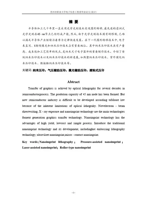
摘要半导体加工几十年里一直采用光学光刻技术实现图形转移,最先进的浸润式光学光刻在45 nm节点已经形成产能,然而,由于光学光刻技术固有的限制,已难以满足半导体产业继续沿着摩尔定律快速发展。
在下一代图形转移技术中,电子束直写、X射线曝光和纳米压印技术占有重要地位。
其中纳米压印技术具有产量高、成本低和工艺简单的优点,是纳米尺寸电子器件的重要制作技术。
介绍了传统纳米压印技术以及纳米压印技术的新进展,如热塑纳米压印技术、紫外固化纳米压印技术、微接触纳米压印技术等。
关键词:纳米压印;气压辅助压印;激光辅助压印;滚轴式压印AbtractTransfer of graphics is achived by oplical lithography for several decades in semiconductorprocess. The prodution capacity of 45 nm node has been formed. But now semiconductor industry is difficult to be developed according toMoore law because of the inherent limitations of oplical lithograhy. Nowelectron - beam directwriting, X - ray exposure and nanoimprint technology are the main technologies fornext generation graphics transfer technology. Nanoimprint technology has the advantages of high yield, lowcost and simple process. Introduce the traditional nanoimprint technology and its development, includinghot embossing lithography technology, ultraviloet nanoimprint,micro - contact nanoimprint.Key words:Nanoimprint lithography;Pressure-assisted nanoimprint;Laser-assisted nanoimprint;Roller-type nanoimprint- i -目录第1章绪论 (1)第2章纳米压印的技术方法..........................错误!未定义书签。
芯片制造过程中用到那些技术合工艺芯片制造过程是一个复杂的系统工程,需要使用多种技术和工艺来完成。
主要包括微电子工艺、半导体工艺、化学制程工艺、材料工程、设备制造、测试与封装等诸多方面。
首先,微电子工艺是芯片制造过程的核心部分。
它是用来控制芯片的结构和性能的一种技术。
其中最重要的是光刻技术,也就是利用光线将芯片的图形或图案投射到硅晶片上的一种制造工艺,它的精度能够达到亚微米级别,这是制造高集成度芯片的一项关键技术。
此外,还有电子束曝光技术、X射线Lithography技术、Nanoimprint Lithography技术等等。
其次,半导体工艺是另一个非常重要的技术。
它是为了使电路元器件能够在硅基板上建立起来而采取的一种工艺。
半导体工艺主要分为两类:沉积和腐蚀。
其中沉积工艺是指将物质沉积在硅基板上,使其形成薄膜的一种工艺,如化学气相沉积、物理气相沉积等;而腐蚀工艺则是将特定区域的硅材料进行腐蚀,制造出需要的器件,如湿法腐蚀、干法腐蚀等。
第三,化学制程工艺也是芯片制造过程中必不可少的一部分。
它主要是为了加工芯片器件而使用的一种工艺。
其中最常见的是电镀工艺,也就是用电流将某种金属沉积到硅片隆凸物上,以便在硅片表面制造出金属接触点和线路。
第四,材料工程是芯片制造过程中同样重要的一环。
它是研究芯片组成材料的性质和应用的一门工程学科。
材料工程常用的材料有硅、氮化硅、氧化铝、多晶硅、金、铜等等。
这些材料的性质,如导电、阻挡、机械强度等等都有很高的要求。
最后,测试与封装是芯片制造中比较后面的工艺环节。
测试技术是用来检验和验证芯片电路功能是否正确的一项技术。
芯片通过完整的电气性能测试后,就要封装了。
选择封装材料、设计封装方案、制定封装工艺流程等都是封装工艺的重要部分,其目的是将成品芯片包装好,以便在其他电子产品中使用。
以上就是芯片制造过程中用到的关键技术和工艺,芯片制造涉及的技术领域很多,需要高度的集成和协调才能让每个工艺环节都可以顺利运转。

专利名称:Nanoimprint lithography 发明人:Stephen Y. Chou申请号:US08/558809申请日:19951115公开号:US05772905A公开日:19980630专利内容由知识产权出版社提供摘要:A lithographic method and apparatus for creating ultra-fine (sub- 25 nm) patterns in a thin film coated on a substrate is provided, in which a mold having at least one protruding feature is pressed into a thin film carried on a substrate. The protruding feature in the mold creates a recess of the thin film. The mold is removed from the film. The thin film then is processed such that the thin film in the recess is removed exposing the underlying substrate. Thus, the patterns in the mold is replaced in the thin film, completing the lithography. The patterns in the thin film will be, in subsequent processes, reproduced in the substrate or in another material which is added onto the substrate.申请人:REGENTS OF THE UNIVERSITY OF MINNESOTA代理机构:Westman, Champlin & Kelly, P更多信息请下载全文后查看。

摘要半导体加工几十年里一直采用光学光刻技术实现图形转移,最先进的浸润式光学光刻在45 nm节点已经形成产能,然而,由于光学光刻技术固有的限制,已难以满足半导体产业继续沿着摩尔定律快速发展。
在下一代图形转移技术中,电子束直写、X射线曝光和纳米压印技术占有重要地位。
其中纳米压印技术具有产量高、成本低和工艺简单的优点,是纳米尺寸电子器件的重要制作技术。
介绍了传统纳米压印技术以及纳米压印技术的新进展,如热塑纳米压印技术、紫外固化纳米压印技术、微接触纳米压印技术等。
关键词:纳米压印;气压辅助压印;激光辅助压印;滚轴式压印AbtractTransfer of graphics is achived by oplical lithography for several decades in semiconductorprocess. The prodution capacity of 45 nm node has been formed. But now semiconductor industry is difficult to be developed according toMoore law because of the inherent limitations of oplical lithograhy. Nowelectron - beam directwriting, X - ray exposure and nanoimprint technology are the main technologies fornext generation graphics transfer technology. Nanoimprint technology has the advantages of high yield, lowcost and simple process. Introduce the traditional nanoimprint technology and its development, includinghot embossing lithography technology, ultraviloet nanoimprint,micro - contact nanoimprint.Key words:Nanoimprint lithography;Pressure-assisted nanoimprint;Laser-assisted nanoimprint;Roller-type nanoimprint- i -目录第1章绪论 (1)第2章纳米压印的技术方法.......................... 错误!未定义书签。
基于ABAQUS的微结构滚压印仿真刘阳;沈连婠;叶回春;李木军【摘要】Based on the finite element method and the ABAQUS software, a 2D model of micro hot embossing process was simulated. The heat curable material PMMA wais employed in the simulation, which was modeled as an elastic perfect-ly-plastic material. The copying rate of the pattern, the maximum width and maximum depth of the copy pattern were taken asthe evaluation criterions. Detailed analysis was made to investigate the influence of various factors, such as pattern size, pattern duty cycle, distance between roller and the polymer, scrolling speed, polymer elastic modulus to the imprinting quality and the imprint pressure. Simulation results showed that the distance between roller and the polymer, the pattern duty cycle and the polymer elastic modulus had impact on the imprinting process seriously. The influence of pattern size and scrolling speed on the embossing results can be ignored.%借助有限元软件ABAQUS,对滚动热压印成型过程进行二维仿真.聚合物材料采用PM-MA的理想弹塑性模型,以图形面积的复制率、图形的最大宽度和最大深度为评定判据,详细分析了滚子与聚合物表面距离、图案大小、图案占空比、滚子的滚动速度、聚合物弹性模量对压印图形质量及压印力的影响.仿真计算结果表明,滚子与聚合物的距离、图案占空比、聚合物的弹性模量对压印图形的质量影响较大,而滚子滚动速度以及图案大小对压印图形的质量影响较小;同时,滚子与聚合物距离、聚合物弹性模量、图案大小对压印力的影响较大,反之,其他的情况基本可以忽略.【期刊名称】《新技术新工艺》【年(卷),期】2012(000)012【总页数】4页(P6-9)【关键词】滚动压印;ABAQUS;有限元仿真;PMMA【作者】刘阳;沈连婠;叶回春;李木军【作者单位】中国科学技术大学,安徽合肥230027;中国科学技术大学,安徽合肥230027;中国科学技术大学,安徽合肥230027;中国科学技术大学,安徽合肥230027【正文语种】中文【中图分类】TH1641995年,普林斯顿大学Y.Chou Stephen提出[1]了一种压印工艺,即在微纳米尺度获得并行复制结构的一种成本低而速度快的方法。
纳米的科技术语的理解
纳米科技是一种应用于纳米尺度的科技,它主要是指在纳米尺度范围内制造、处理、分析和应用材料、物理、化学、生物学和工程学等多学科的方法和技术。
以下是一些与纳米科技相关的术语解释:
1. 纳米(Nanometer):表示一种长度单位,相当于十亿分之一米。
2. 纳米技术(Nanotechnology):指将材料加工到纳米级别,从而能够控制和利用材料的物理、化学和生物特性的一种技术。
3. 纳米材料(Nanomaterial):指在纳米尺寸下制造的材料,通常具有比同种材料更优异的性质,如强度、导电性等。
4. 纳米管(Nanotube):是一种碳纳米管,是由单层碳原子螺旋而成的管状结构,具有很高的强度和导电性。
5. 纳米颗粒(Nanoparticle):指在纳米尺寸下制造的微小颗粒,具有很高的表面积和反应性,可用于医学、能源、环保等领域。
6. 自组装(Self-assembly):是指分子或纳米材料在没有外部干预的情况下自行组装成一定的结构。
7. 纳米印刷(Nanoimprint lithography):是一种通过压印的方式制造纳米结构的技术,具有高分辨率和高产量的优点。
8. 纳米机器人(Nanorobot):是一种在纳米尺度范围内制造的机器人,能够对物质进行精确操作,具有广泛的应用前景。
纳米科技是一个快速发展的领域,其应用领域涉及医学、能源、材料、信息等多个领域。
理解这些纳米科技的术语和概念,能够更好地了解和把握纳米科技的发展趋势和应用前景。
纳米压印光刻胶赵彬1,张静2,周伟民2,王金合2,刘彦伯2,张燕萍2,施利毅1,张剑平1*1.上海大学理学院化学系,上海2004442.上海市纳米科技与产业发展促进中心纳米核心技术实验室,上海200237摘要:光刻胶是纳米压印关键材料,其性能将影响压印图形复制精度、图形缺陷率和图形向底材转移时刻蚀选择性。
文中提出了成膜性能、硬度粘度、固化速度、界面性质、抗刻蚀能力等压印光刻胶的性能指标。
并根据工艺特点和材料成分对光刻胶分类,介绍了热压印光刻胶、紫外压印光刻胶、步进式光刻胶和滚动压印式光刻胶的特点以及碳氧类纯有机材料、有机氟材料、有机硅材料做压印光刻胶的优缺点。
列举了热压印、紫外压印、步进压印工艺中具有代表性的光刻胶实例,详细分析了其配方中各组分的比例和作用。
介绍了可降解光刻胶的原理。
展望了压印光刻胶的发展趋势。
关键词:纳米压印;热压印光刻胶;紫外压印光刻胶;有机硅光刻胶;含氟光刻胶Introduction to Nanoimprint Lithography Resist Zhao Bin1, Zhang Jing2,Zhou Weimin2, Wang Jinhe2 ,Liu Yanbo2 ,Zhang Yanping2 ,Shi Liyi1,Zhang Jianpin1*1.Chemistry department ,School of Science, Shanghai University, Shanghai 200444, Chinaboratory of Nanotechnology, Shanghai Nanotechnology Promotion Center (SNPC), Shanghai 200237, China Resist is a key material for nanoimprint lithography (NIL). Its property influence the accuracy of transferred patterns, defects rate and etch selectivity of NIL significantly. A suitable resist material is of great importance for successful imprinting. In this paper, requirements of a imprint resist, such as coating ability, viscosity, modulus, curing rates, interfacial energy and etch resistance are discussed. Different categories of imprint resists sorted by different nanoimprint lithography (such as hot embossing lithography, UV-nanoimprint lithography, step and flash nanoimprint lithography and roll-to-roll nanoimprint lithography) and main component (such as carbon-oxygen compound, carbon-fluorine compound and carbon-silicon compound) are introduced. Some classical prescriptions of hot embossing resist, UV-nanoimprint resist and step-by-step nanoimprint resist are analyzed detailedly, including each component function and quantity in each prescription. In the end the principle of degradable imprint resist are discussed and the development tendency of imprint resists are given.Key words: nanoimprint lithography;hot embossing resist; UV-nanoimprint resist; floroupolymer; silicone polymer0 引言纳米压印是受到广泛关注的下一代光刻技术,高精度、高分辨率、廉价的特点使其很可能成为下一代主流光刻技术,麻省理工大学的一篇评论称之为可能改变世界的十大技术之一[1]。
NIL工艺技术NIL工艺技术(Nanoimprint Lithography)是一种先进的纳米加工技术,属于纳米印刷领域。
NIL工艺技术主要通过将硅基材料与模板结合,使模板上的微纳米结构复制到硅基材料上,从而实现对纳米级图案的制造。
这种技术具有高分辨率、高速度和低成本等特点,在纳米电子、纳米光学、生物医药等领域有着广泛的应用前景。
NIL工艺技术的工作原理相对简单,主要分为热压印刷和UV 固化两种方式。
热压印刷是指利用加热和压力将模板上的微纳米结构转移到硅基材料上的过程。
UV固化是指利用紫外线照射硅基材料,并结合模板上的微纳米结构,从而实现模式化的硅基材料。
在具体操作过程中,首先将模板上的微纳米结构与硅基材料结合,然后通过热或光的作用,使硅基材料融化或固化,最后分离模具,即可得到所需的纳米图案。
NIL工艺技术在纳米电子领域的应用有着广泛的前景。
由于NIL工艺技术的高分辨率特点,它可以制造出尺寸极小的电子元件,例如纳米晶体管,从而提高电子器件的性能。
此外,NIL工艺技术还可以制备多层薄膜电路,这对于集成电路的制造非常重要。
据研究,NIL工艺技术制造的纳米电子元件比传统的光刻技术制造的元件具有更高的电子迁移速度和更低的电流漏失。
在纳米光学领域,NIL工艺技术也有着重要的应用。
它可以制造出高精度的光学波导,用于光信号的传输和操控。
此外,NIL工艺技术还可以制造出微透镜阵列,用于显微镜、投影仪等光学设备中。
研究表明,利用NIL工艺技术制造的光学器件具有更高的光学传导效率和更快的响应速度。
在生物医药领域,NIL工艺技术的应用也变得越来越重要。
利用NIL工艺技术制造的纳米结构可以应用于药物传递、细胞培养和生物传感器等领域。
NIL工艺技术可以制造出光吸附、碳纳米管和高分子膜等纳米载体,用于药物的包裹和释放。
同时,NIL工艺技术还可以制造出纳米图案的微流控芯片,用于细胞分离和分析。
研究显示,利用NIL工艺技术制造的纳米结构能够更好地模拟生物体内的微环境,从而提高生物医药领域的研究和治疗效果。
纳米压印光刻法基本流程图Nanometer imprint lithography, also known as nanoimprint lithography (NIL), is a promising technique for fabricating nanostructures with high resolution. This technique has gained significant attention in the field of nanotechnology due to its potential applications in various areas such as nanoelectronics, optoelectronics, and biotechnology. 纳米压印光刻,也被称为纳米压印微影(NIL),是一种用于制作高分辨率纳米结构的有前景的技术。
由于在纳米电子学、光电子学和生物技术等各个领域具有潜在的应用,这种技术在纳米技术领域引起了极大的关注。
The basic process of nanometer imprint lithography involves several key steps including substrate preparation, imprinting, resist curing, and pattern transfer. These steps are crucial in determining the quality and resolution of the final nanostructures. 纳米压印光刻的基本流程包括基板准备、压印、光刻胶固化和图案转移等几个关键步骤。
这些步骤对最终纳米结构的质量和分辨率具有至关重要的影响。
The first step in the nanometer imprint lithography process is substrate preparation, which involves cleaning the substrate surfaceto remove any contaminants or particles that may interfere with the imprinting process. Proper cleaning and surface treatment of the substrate are essential for achieving high-quality nanostructures. 纳米压印光刻过程中的第一步是基板准备,这涉及清洁基板表面,以去除可能干扰压印过程的任何污染物或颗粒。
微机电系统工程专业英语词汇微机电工程材料该课程介绍了微机电系统中常用的材料的性质、选择和应用,包括金属、半导体、陶瓷、聚合物等。
该课程涉及的专业英语词汇如下:中文英文微机电系统Microelectromechanical Systems (MEMS)材料Material性质Property选择Selection应用Application金属Metal半导体Semiconductor陶瓷Ceramic聚合物Polymer晶体结构Crystal structure晶格常数Lattice constant晶向Crystal orientation晶面Crystal plane点阵Lattice基元Primitive cell单位晶胞Unit cell晶界Grain boundary缺陷Defect掺杂Doping禁带宽度Band gap width载流子Carrier导电性Conductivity阻值Resistance应力Stress应变Strain弹性模量Elastic modulus泊松比Poisson's ratio热膨胀系数Thermal expansion coefficient热导率Thermal conductivity热容量Heat capacity熔点Melting point硬度Hardness韧性Toughness耐腐蚀性Corrosion resistance中文英文表面粗糙度Surface roughness表面处理Surface treatment氧化层Oxide layer沉积方法Deposition method微机电器件与系统该课程介绍了微机电系统中常见的器件和系统的原理、结构和功能,包括传感器、执行器、开关、滤波器、振荡器等。
该课程涉及的专业英语词汇如下:中文英文微机电器件与系统Microelectromechanical Devices and Systems (MEDS)原理Principle结构Structure功能Function传感器Sensor执行器Actuator开关Switch滤波器Filter振荡器Oscillator振动Vibration静电力Electrostatic force电容Capacitance电感Inductance电阻Resistance压电效应Piezoelectric effect热电效应Thermoelectric effect磁电效应Magneto-electric effect光电效应Photoelectric effect声波Acoustic wave表面声波Surface acoustic wave (SAW)布拉格反射器Bragg reflector共振腔Resonant cavity质量灵敏度Mass sensitivity频率响应Frequency response功率消耗Power consumption信噪比Signal-to-noise ratio (SNR)线性度Linearity稳定性Stability可靠性Reliability微机械学该课程介绍了微机械系统的基本理论和方法,包括微尺度下的力学、流体力学、热力学、电磁学等。
Roller nanoimprint lithographyHua Tan a)NanoStructure Laboratory,Department of Electrical Engineering,Princeton University,Princeton,New Jersey08544Andrew GilbertsonDepartment of Mechanical Engineering,University of Minnesota,Minneapolis,Minnesota55455Stephen Y.ChouNanoStructure Laboratory,Department of Electrical Engineering,Princeton University,Princeton,New Jersey08544͑Received29May1998;accepted28September1998͒An alternative approach toflat nanoimprint lithography͑NIL͒—roller nanoimprint lithography ͑RNIL͒is pared withflat NIL,RNIL has the advantage of better uniformity,less force,and the ability to repeat a mask continuously on a large substrate.Two methods for RNIL are developed:͑a͒rolling a cylinder mold on aflat,solid substrate;͑b͒putting aflat mold directly ona substrate and rolling a smooth roller on top of the ing our current roller nanoimprintsystem,sub-100nm resolution pattern transfer has been achieved.©1998American Vacuum Society.͓S0734-211X͑98͒18606-7͔I.INTRODUCTIONNanoimprint lithography͑NIL͒is a new lithographicmethod that offers a sub-10nm feature size,high throughput,and low cost.1,2In previous NIL experiments,an entireflatmold is pressed simultaneously into a polymer cast on aflatsubstrate.Here,we demonstrate an alternative approach toflat imprint lithography—roller nanoimprint lithography ͑RNIL͒.We report the design and construction of a roller nanoimprint system,the development of two methods forroller nanoimprint,and the demonstration of sub-100nm pat-terns by RNIL.Previously,roller presses were used in thecement industry3,4and was used to imprint intoflexible thinfilms that can conform to the shape of the roller.However,the pressed feature size in these applications is a micron orlarger and they are not used as a lithography method.II.ROLLER NIL MACHINE DESIGNOur roller press consists of a roller,a movable platform,and a hinge͑Fig.1͒.5The roller is a hollow metal tube witha halogen bulb mounted inside.It has a thin wall and a smallthermal mass,and therefore can be heated and cooledquickly.Theflat platform that holds a sample can be heatedby a strip heater inside,and has two ball-ring rails under-neath allowing the platform to move back and forth freely inthe direction vertical to the roller.The hinge is for applyinga constant force between the roller and the sample.Pressurecan be adjusted by applying different weight to the top hinge.The mold can either be bent into a cylinder shape or be putdirectly on the sample.During RNIL,the roller rotatesaround afixed axis,while the platform slides underneath theroller.III.TWO METHODS FOR ROLLER NANOIMPRINT We have developed two methods for RNIL͑Fig.2͒.Onemethod is the cylinder mold method.The cylinder mold wasmade by bending a thin metalfilm mold around a smoothroller.In particular,a compact disk master made of100m thick of Ni with700-nm-wide tracks was used.The substrateis aflat Si wafer of0.5mm thickness with220nm polym-ethylmethacrylate͑PMMA͒cast on top.During roller NIL,the mold is pressed into the PMMA resist,and the rotation ofthe roller pushes the sample forward.The second method,theflat mold method,uses aflat Siwafer mold of0.5mm thickness with intrusions of190nmperiod and180nm height,placed directly on the substrate.Asmooth roller is rotated over the mold and the slight defor-mation of theflat mold under the pressure of the roller im-prints patterns in the resist.In both methods,the roller temperature is set well abovethe glass transition temperature,T g,of the resist,while thetemperature of the platform is set below the T g.Therefore,only the area in contact with the roller has a temperaturehigher than T g,making the resist in that areaflow and beingimprinted with patterns.This is different fromflat nanoim-print,where the entire resist,heated above T g,is imprintedsimultaneously and the pressure is applied until the resist iscooled down,becoming hardened.IV.RESULTS AND DISCUSSIONIn either roller NIL method,we have been able to dupli-cate the mold pattern into the PMMA resist continuously.Inthefirst method,the compact disk master we used had mesapatterns of700nm width͑Fig.3͒.After roller nanoimprint,atomic force microscope͑AFM͒images showed that thetrenches imprinted in PMMA are700nm wide,60nm deep ͑Fig.4͒.Due to the AFM tip size effects,the imprinted AFM image has rounded sidewalls.In the second method,theflatmold has a large area grating pattern of190nm period anda͒Electronic mail:htan@39263926 J.Vac.Sci.Technol.B16…6…,Nov/Dec19980734-211X/98/16…6…/3926/3/$15.00©1998American Vacuum Society180nm height.6After RNIL we obtained a large area grating with 190nm period and 40nm depth.The width of the PMMA grating is 70nm ͑Fig.5͒.The sloped PMMA side-wall and the shallow trench are due to the AFM tip size effect.The RNIL processing conditions have been investigated.The temperature of the platform was varied between room temperature and 200°C,and the temperature of the roller was varied between 120and 200°C.The scan speed of the roller ranged from 0.5to 1.5cm/min,and the estimated pres-sure was changed from 300to 4800psi.The pressure was estimated from the total force and the total contact area ͑the sample width times the contact length ͒.The total force ranged from 10to 20lbs.The sample width was from 0.25to 2cm,and the contact length,which is a function of the pressure,was about 2mm.The temperatures and pressures for the two roller NIL methods are different because the molds are different in bothmaterial and feature size.We found that for the cylinder mold method,the best result can be achieved when the plat-form temperature is around 50°C and the roller temperature is at 170–200°C.For the flat mold method,the best tem-perature for pattern transfer would be around 70°C for the platform and 170–200°C for the roller.Furthermore,it is found that the temperature and pressure are related.Increase of the platform temperature would decrease the viscosity of the PMMA,therefore less imprint pressure is required.The roller temperature seems not critical to the press as long as it ranges from 160to 200°C.We found that when the platform temperature is too high,or the roller moving speed is too fast,or the pressure isnotF IG .1.Schematic of a roller nanoimprint system,consisting of a roller,a movable platform,a hinge,andheaters.F IG .2.Two ways for roller nanoimprint:͑a ͒imprints using a cylinder mold:bending a compact master disk into cylinder shape,mounting it around the roller,and rolling the roller on the substrate;͑b ͒imprints using a flat mold:putting the mold directly on the substrate,and rotating the roller on top of themold.F IG .3.AFM graph of a compact disk mold before bent into a cylinder:700nm tracks pattern on the surface of compactdisk.F IG .4.PMMA imprinted by a cylinder mold,showing sub-100nm accuracy in pattern transfer.JVST B -Microelectronics and Nanometer Structuressufficient,the imprint quality becomes poor.At high plat-form temperature͑e.g.,higher than100°C for PMMA͒,once the pressure is removed,the imprinted pattern deforms quickly due to the low viscosity.At fast roller speed or at lower pressure,the resist may not have enough time to change its shape,depending upon the resist viscosity.Inspection using optical microscope and AFM showed that RNIL has few air bubbles,even when imprinted in at-mosphere,perhaps because the roller pushes the air out.Duringflat nanoimprint,the whole area of the sample is imprinted at the same time.Unevenness in sample thickness or a small dust particle in one place can affect the uniformity of a large surrounding area.But for RNIL,only a line area is in contact for a given time,significantly reducing the effects of thickness unevenness and dust on surrounding area.How-ever,the actual uniformity depends on the RNIL machine being used.We are still improving our RNIL machine.Finally,We would like to point out that both the RNIL machine and the process need further improvements for a better uniformity,smaller feature size,and larger area.V.SUMMARYA roller NIL machine was designed and constructed.Two methods for roller nanoimprint lithography have been devel-oped with one using a roller mold and the other using aflat mold and a smooth roller.In both methods,sub-100nm reso-lution has been achieved.Our results indicate that roller NIL is an attractive alternative approach,offering a much simpler NIL machine,higher throughput,and lower cost.1S.Y.Chou,P.R.Krauss,and P.J.Renstrom,Appl.Phys.Lett.67,3114͑1995͒;Science272,85͑1996͒.2S.Y.Chou,P.R.Krauss,and P.J.Renstrom,J.Vac.Sci.Technol.B14, 4129͑1996͒.3G.H.Conroy,IEEE Trans.Ind.Appl.30,561͑1994͒.4A.J.Kreisberg,IEEE Trans.Ind.Appl.28,954͑1992͒.5S.Y.Chou͑unpublished͒.6W.Wu, B.Cui,X.Sun,W.Zhang,and S.Y.Chou,Presented at EIPBN’98͑unpublished͒.F IG. 5.PMMA imprinted by aflat mold:it has large area grating with 190nm period and40nm depth, showing a sub-100nm resolution.。