
电气与信息学院自动化专业毕业设计(论文)外文翻译
Electonic power steering system Research and Design 电子动力转向系统的研究与设计
注:本毕业设计(论文)外文翻译文档前半部分为英文部分,后半部分为中文部分。本外文翻译由专业人员翻译,内容详细数据全面,得到导师的一致好评。值得大家借鉴参考。本文档下载后为WORD版本,可按需直接编辑。
Electronic power steering system
What it is
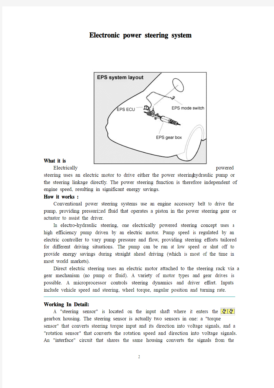
Electrically powered steering uses an electric motor to drive either the power steering hydraulic pump or the steering linkage directly. The power steering function is therefore independent of engine speed, resulting in significant energy savings.
How it works :
Conventional power steering systems use an engine accessory belt to drive the pump, providing pressurized fluid that operates a piston in the power steering gear or actuator to assist the driver.
In electro-hydraulic steering, one electrically powered steering concept uses a high efficiency pump driven by an electric motor. Pump speed is regulated by an electric controller to vary pump pressure and flow, providing steering efforts tailored for different driving situations. The pump can be run at low speed or shut off to provide energy savings during straight ahead driving (which is most of the time in most world markets).
Direct electric steering uses an electric motor attached to the steering rack via a gear mechanism (no pump or fluid). A variety of motor types and gear drives is possible. A microprocessor controls steering dynamics and driver effort. Inputs include vehicle speed and steering, wheel torque, angular position and turning rate.
Working In Detail:
A "steering sensor" is located on the input shaft where it enters the
sensor" that converts steering torque input and its direction into voltage signals, and a "rotation sensor" that converts the rotation speed and direction into voltage signals. An "interface" circuit that shares the same housing converts the signals from the
torque sensor and rotation sensor into signals the control electronics can process. Inputs from the steering sensor are digested by a microprocessor control unit that also monitors input from the vehicle's speed sensor. The sensor inputs are then compared to determine how much power assist is required according to a preprogrammed "force map" in the control unit's memory. The control unit then sends out the appropriate command to the "power unit" which then supplies the electric motor with current. The motor pushes the rack to the right or left depending on which way the voltage flows (reversing the current reverses the direction the motor spins). Increasing the current to the motor increases the amount of power assist.
The system has three operating modes: a "normal" control mode in which left or right power assist is provided in response to input from the steering torque and rotation sensor's inputs; a "return" control mode which is used to assist steering return after completing a turn; and a "damper" control mode that changes with vehicle speed to improve road feel and dampen kickback.
If the steering wheel is turned and held in the full-lock position and steering assist reaches a maximum, the control unit reduces current to the electric motor to prevent an overload situation that might damage the motor. The control unit is also designed to protect the motor against voltage surges from a faulty alternator or charging problem.
The electronic steering control unit is capable of self-diagnosing faults by monitoring the system's inputs and outputs, and the driving current of the electric motor. If a problem occurs, the control unit turns the system off by actuating a fail-safe relay in the power unit. This eliminates all power assist, causing the system to revert back to manual steering. A dash EPS warning light is also illuminated to alert the driver. To diagnose the problem, a technician jumps the terminals on the service check connector and reads out the trouble codes.
click here to see a bigger
Electric power steering systems promise weight reduction, fuel savings and package flexibility, at no cost penalty.
Europe's high fuel prices and smaller vehicles make a fertile testbed for electric steering, a technology that promises automakers weight savings and fuel economy gains. And in a short time, electric steering will make it to the U.S., too. "It's just just a matter of time," says Aly Badawy, director of research and development for Delphi Saginaw Steering Systems in Saginaw, Mich. "The issue was cost and that's behind us now. By 2002 here in the U.S. the cost of electric power steering will absolutely be a wash over hydraulic."
Today, electric and hybrid-powered vehicles (EV), including Toyota's Prius and GM's EV-1, are the perfect domain for electric steering. But by 2010, a TRW Inc. internal study estimates that one out of every three cars produced in the world will be equipped with some form of electrically-assisted steering. The Cleveland-based supplier claims its new steering systems could improve fuel economy by up to 2 mpg, while enhancing handling. There are true bottom-line benefits as well for automakers by reducing overall costs and decreasing assembly time, since there's no need for pumps, hoses and fluids.
Another claimed advantage is shortened development time. For instance, a Delphi group developed E-TUNE, a ride-and-handling software package that can be run off a laptop computer. "They can take that computer and plug it in, attach it to the controller and change all the handling parameters -- effort level, returnability, damping -- on the fly," Badawy says. "It used to take months." Delphi has one OEM customer that should start low-volume production in '99.Electric steering units are normally placed in one of three positions: column-drive, pinion-drive and rack-drive. Which system will become the norm is still unclear. Short term, OEMs will choose the steering system that is easiest to integrate into an existing platform. Obviously,
greater potential comes from designing the system into an all-new platform."We have all three designs under consideration," says Dr. Herman Strecker, group vice president of steering systems division at ZF in Schwaebisch Gmuend, Germany. "It's up to the market and OEMs which version finally will be used and manufactured.""The large manufacturers have all grabbed hold of what they consider a core technology," explains James Handysides, TRW vice president, electrically assisted steering in Sterling Heights, Mich. His company offers a portfolio of electric steering systems (hybrid electric, rack-, pinion-, and column-drive). TRW originally concentrated on what it still believes is the purest engineering solution for electric steering--the rack-drive system. The system is sometimes refered to as direct drive or ball/nut drive.Still, this winter TRW hedged its bet, forming a joint venture with LucasVarity. The British supplier received $50 million in exchange for its electric column-drive steering technology and as sets. Initial production of the column and pinion drive electric steering systems is expected to begin in Birmingham, England, in 2000.
"What we lack is the credibility in the steering market," says Brendan Conner, managing director, TRW/LucasVarity Electric Steering Ltd. "The combination with TRW provides us with a good opportunity for us to bridge that gap." LucasVarity currently has experimental systems on 11 different vehicle types, mostly European. TRW is currently supplying its EAS systems for Ford and Chrysler EVs in North America and for GM's new Opel Astra.
In 1995, according to Delphi, traditional hydraulic power steering systems were on 7596 of all vehicles sold globally. That 37-million vehicle pool consumes about 10 million gallons in hydraulic fluid that could be superfluous, if electric steering really takes off.
The present invention relates to an electrically powered drive mechamsm for providing powered assistance to a vehicle steering mechanism. According to one aspect of the present invention, there is provided an electrically powered driven mechanism for providing powered assistance to a vehicle steering mechanism having a manually rotatable member for operating the steering mechanism, the drive mechanism including a torque sensor operable to sense torque being manually applied to the rotatable member, an electrically powered drive motor drivingly connected to the rotatable member and a controller which is arranged to control the speed and direction of rotation of the drive motor in response to signals received from the torque sensor, the torque sensor including a sensor shaft adapted for connection to the rotatable member to form an extension thereof so that torque is transmitted through said sensor shaft when the rotatable member is manually rotated and a strain gauge mounted on the sensor shaft for producing a signal indicative of the amount of torque being transmitted through said shaft.Preferably the sensor shaft is non-rotatably mounted at one axial end in a first coupling member and is non-rotatably mounted at its opposite axial end in a second coupling member, the first and second coupling members being inter-engaged to permit limited rotation therebetween so that torque under a predetermined limit is transmitted by the sensor shaft only and so that torque above said predetermined limit is transmitted through the first and second coupling members.The first and second coupling members are preferably arranged to act as a
bridge for drivingly connecting first and second portions of the rotating member to one another.Preferably the sensor shaft is of generally rectangular cross-section throughout the majority of its length.Preferably the strain gauge includes one or more SAW resonators secured to the sensor shaft.Preferably the motor is drivingly connected to the rotatable member via a clutch.Preferably the motor includes a gear box and is concentrically arranged relative to the rotatable member.Various aspects of the present invention will hereafter be described, with reference to the accompanying drawings, in which :Figure 1 is a diagrammatic view of a vehicle steering mechanism including an electrically powered drive mechanism according to the present invention,Figure 2 is a flow diagram illustrating interaction between various components of the drive mechanism shown in Figure 1 ,Figure 3 is an axial section through the drive mechanism shown in Figure 1, Figure 4 is a sectional view taken along lines IV-IV in Figure 3,Figure 5 is a more detailed exploded view of the input drives coupling shown in Figure 3, andFigure 6 is a more detailed exploded view of the clutch showing in Figure 3. Referring initially to Figure 1 , there is shown a vehicle steering mechanism 10 drivingly connected to a pair of steerable road wheels The steering mechanism 10 shown includes a rack and pinion assembly 14 connected to the road wheels 12 via joints 15. The pinion(not shown) of assembly 14 is rotatably driven by a manually rotatable member in the form of a steering column 18 which is manually rotated by a steering wheel 19.The steering column 18 includes an electric powered drive mechanism 30 which includes an electric drive motor (not shown in Figure 1) for driving the pinion in response to torque loadings in the steering column 18 in order to provide power assistance for the operative when rotating the steering wheel 19.As schematically illustrated in Figure 2, the electric powered drive mechanism includes a torque sensor20 which measures the torque applied by the steering column 18 when driving the pinion and supplies a signal to a controller 40. The controller 40 is connected to a drive motor 50 and controls the electric current supplied to the motor 50 to control the amount of torque generated by the motor 50 and the direction of its rotation.The motor 50 is drivingly connected to the steering column 18 preferably via a gear box 60, preferably an epicyclic gear box, and a clutch 70. The clutch 70 is preferably permanently engaged during normal operation and is operative under certain conditions to isolate drive from the motor 50 to enable the pinion to be driven manually through the drive mechanism 30. This is a safety feature to enable the mechanism to function in the event of the motor 50 attempting to drive the steering column too fast and/or in the wrong direction or in the case where the motor and/or gear box have seized.
The torque sensor 20 is preferably an assembly including a short sensor shaft on which is mounted a strain gauge capable of accurately measuring strain in the sensor shaft brought about by the application of torque within a predetermined range.Preferably the predetermined range of torque which is measured is 0-lONm; more preferably is about l-5Nm.Preferably the range of measured torque corresponds to about 0-1000 microstrain and the construction of the sensor shaft is chosen such that a torque of 5Nm will result in a twist of less than 2° in the shaft, more preferably less than 1 °.Preferably the strain gauge is a SAW resonator, a suitable SAW
resonator being described in WO91/13832. Preferably a configuration similar to that shown in Figure 3 of WO91/13832 is utilised wherein twoSAW resonators are arranged at 45° to the shaft axis and at 90° to one another.Preferably the resonators operate with a resonance frequency of between 200-400 MHz and are arranged to produce a signal to the controller 40 of 1 MHz ±500 KHz depending upon the direction of rotation of the sensor shaft. Thus, when the sensor shaft is not being twisted due to the absence of torque, it produces a 1 MHz signal.When the sensor shaft is twisted in one direction it produces a signal between 1.0 to 1.5 MHz. When the sensor shaft is twisted in the opposite direction it produces a signal between 1.0 to 0.5 MHz. Thus the same sensor is able to produce a signal indicative of the degree of torque and also the direction of rotation of the sensor shaft.Preferably the amount of torque generated by the motor in response to a measured torque of between 0-10Nm is 0-40Nm and for a measured torque of between l-5Nm is 0-25Nm.Preferably a feed back circuit is provided whereby the electric current being used by the motor is measured and compared by the controller 40 to ensure that the motor is running in the correct direction and providing the desired amount of power assistance. Preferably the controller acts to reduce the measured torque to zero and so controls the motor to increase its torque output to reduce the measured torque.A vehicle speed sensor (not shown) is preferably provided which sends a signal indicative of vehicle speed to the controller. The controller uses this signal to modify the degree of power assistance provided in response to the measured torque.Thus at low vehicle speeds maximum power assistance will be provided and a high vehicle speeds minimum power assistance will be provided.The controller is preferably a logic sequencer having a field programmable gate array for example a XC 4005 as supplied by Xilinx. Such a controller does not rely upon software and so is able to function more reliably in a car vehicle environment. It is envisaged that a logic sequence not having a field programmable array may be used.
Electronic power steering system (English as EPS), and hydraulic power steering system (HPS) compared to, EPS has many advantages.
The advantage is that the EPS:
1) high efficiency. HPS efficiency is very low, generally 60% to 70%, while EPS and electrical connections, high efficiency, and some can be as high as 90 percent.
2) less energy consumption. Automobile traffic in the actual process, at the time to about 5 percent of the time travelling, the HPS system, engine running, the pumps will always be in working condition, the oil pipeline has been in circulation, so that vehicle fuel consumption rate by 4 % To 6%, while EPS only when needed for energy, vehicle fuel consumption rates only increased by 0.5 percent.
3) "Road sense of" good. Because EPS internal use of rigid, system of the lag can be controlled by software, and can be used in accordance with the operation of the driver to adjust.
4) back to being good. EPS simple structure of small internal resistance, is a good back, get back to being the best characteristics, improve vehicle handling and stability.
5) little environmental pollution. HPS hydraulic circuit in the hydraulic hoses and connectors, the existence of oil leaking, but hydraulic hoses can not be recovered, the environmental pollution are to a certain extent, while EPS almost no pollution to the environment.
6) can be independent of the engines work. EPS for battery powered devices, as long as sufficient battery power, no matter what the condition for the engine, can produce power role.
7) should have a wide range.
8) easy to assemble and good layout.
Now, power steering systems of some cars have become the standard-setting, the whole world about half of the cars used to power steering. With the development of automotive electronics technology, some cars have been using electric power steering gear, the car of the economy, power and mobility has improved. Electric power steering device on the car is a new power steering system device, developed rapidly in recent years both at home and abroad, because of its use of programmable electronic control devices, the flexibility in the same time there are also potential safety problems. In the analysis This unique product on the basis of the author of the characteristics of electronic control devices, security clearance just that the factors that deal with security measures, and discussed a number of concerns the safety of specific issues. The results show that : Existing standards can not meet the electric power steering device security needs and made the electric power steering device safety evaluation of the idea. Research work on the electric power steering device development and evaluation of reference value.
电子动力转向系统
图1
电子动力转向系统的工作原理
电子动力转向系统是通过一个电动机来驱动动力方向盘液压泵或直接驱动转向联动装置。
电子动力转向的功能由于不依赖于发动机转速,所以能节省能源电子动力转向系统是这样运行的
传统的动力方向盘系统使用一条引擎辅助传送带驾驶泵浦,提供操作在动力方向盘齿轮或作动器的一个活塞协助司机的被加压的流体。在电动液压的指点,一个电子动力方向盘概念使用一台电动机驾驶的一个高效率泵浦。泵浦速度是由一个电控制器调控的变化泵浦压力和流程,提供被剪裁的指点努力为不同的驾驶的情况。泵浦可以跑在低速或关闭提供节能在大多时间在多数世界市场上)直向前的驾驶期间(直接电指点使用一台电动机附加指点机架通过齿轮机构(没有泵浦或流体)。各种各样的马达
类型和齿轮驱动是可能的。 微处理器控制指点动力学和司机努力。 输入包括车速和指点、轮子扭矩,角位和转动率。
工作运行时的具体细节: A “指点传感器”位于它进入传动箱住房的输入轴。 指点传感器实际上是在一个的二个传感器: 那“扭矩的传感器”
转换指点扭矩输入和它的方向成电压信号,并且那“自转的传感器”转换转动速度和方向成电压信号。 分享同一套住房的“接口”电路转换从扭矩传感器和自转传感器的信号成控制电子学可能处理的信号。从指点传感器的输入由那微处理器的控制单元消化也监测从车速传感器的输入。 传感器输入然后被比较确定多少机械化根据一张被预编程序的“力量地图”需要在控制单元的记忆。 控制单元然后派出适当的命令对然后供给电动机以潮流的“电源装置”。 马达推挤机架在右边或左根据哪个方式电压流动(扭转潮流扭转方向马达旋转)。 增加潮流对马达增加功率协助。系统有三种操作方式: 左边或右边机械化提供以回应从指点扭矩和自转传感器的输入的输入的“正常”控制方式; 被用于在完成轮以后协助指点回归的“回归”控制方式; 并且改变与车速改进路感受和挫伤佣金的“更加潮湿的”控制方式。如果方向盘被转动,并且举行在充分锁位置和指点协助到达最大值,控制单元使潮流降低到电动机防止也许损坏马达的超载情况。 控制单元也被设计保护马达以防止电压浪涌免受一个有毛病的交流发电机或充电的问题。
毕业设计(论文)原创性声明和使用授权说明 原创性声明 本人郑重承诺:所呈交的毕业设计(论文),是我个人在指导教师的指导下进行的研究工作及取得的成果。尽我所知,除文中特别加以标注和致谢的地方外,不包含其他人或组织已经发表或公布过的研究成果,也不包含我为获得及其它教育机构的学位或学历而使用过的材料。对本研究提供过帮助和做出过贡献的个人或集体,均已在文中作了明确的说明并表示了谢意。 作者签名:日期: 指导教师签名:日期: 使用授权说明 本人完全了解大学关于收集、保存、使用毕业设计(论文)的规定,即:按照学校要求提交毕业设计(论文)的印刷本和电子版本;学校有权保存毕业设计(论文)的印刷本和电子版,并提供目录检索与阅览服务;学校可以采用影印、缩印、数字化或其它复制手段保存论文;在不以赢利为目的前提下,学校可以公布论文的部分或全部内容。 作者签名:日期:
学位论文原创性声明 本人郑重声明:所呈交的论文是本人在导师的指导下独立进行研究所取得的研究成果。除了文中特别加以标注引用的内容外,本论文不包含任何其他个人或集体已经发表或撰写的成果作品。对本文的研究做出重要贡献的个人和集体,均已在文中以明确方式标明。本人完全意识到本声明的法律后果由本人承担。 作者签名:日期:年月日 学位论文版权使用授权书 本学位论文作者完全了解学校有关保留、使用学位论文的规定,同意学校保留并向国家有关部门或机构送交论文的复印件和电子版,允许论文被查阅和借阅。本人授权大学可以将本学位论文的全部或部分内容编入有关数据库进行检索,可以采用影印、缩印或扫描等复制手段保存和汇编本学位论文。 涉密论文按学校规定处理。 作者签名:日期:年月日 导师签名:日期:年月日
毕业论文管理系统分析与设计 班级:信息管理与信息系统 1102 指导教师:黄立明 学号: 0811110206 姓名:高萍
毕业论文管理系统 摘要 (3) 一.毕业论文管理系统的系统调研及规划 (3) 1.1 项目系统的背景分析 (3) 1.2毕业论文信息管理的基本需求 (3) 1.3 毕业论文管理信息系统的项目进程 (4) 1.4 毕业论文信息管理系统的系统分析 (4) 1.4.1系统规划任务 (4) 1.4.2系统规划原则 (4) 1.4.3采用企业系统规划法对毕业论文管理系统进行系统规划 (5) 1.4.3.1 准备工作 (5) 1.4.3.2定义企业过程 (5) 1.4.3.3定义数据类 (6) 1.4.3.4绘制UC矩阵图 (7) 二.毕业论文管理系统的可行性分析 (8) 2.1.学院毕业论文管理概况 (8) 2.1.1毕业论文管理的目标与战略 (8) 2.2拟建的信息系统 (8) 2.2.1简要说明 (8) 2.2.2对组织的意义和影响 (9) 2.3经济可行性 (9) 2.4技术可行性 (9) 2.5社会可行性分析 (9) 2.6可行性分析结果 (10) 三.毕业论文管理系统的结构化分析建模 (10) 3.1组织结构分析 (10) 3.2业务流程分析 (11) 3.3数据流程分析 (11) 四.毕业论文管理系统的系统设计 (13) 4.1毕业论文管理系统业务主要包括 (13) 4.2毕业论文管理系统功能结构图 (13) 4.3代码设计 (14) 4.4,输入输出界面设计 (15) 4.4.1输入设计 (15) 4.4.2输出设计 (15) 4.5 数据库设计 (15) 4.5.1需求分析 (15) 4.5.2数据库文件设计 (16) 4.5.2数据库概念结构设计 (17) 五.毕业论文管理系统的系统实施 (18) 5.1 开发环境 (18) 5.2 调试与测试过程 (19)
电子信息工程专业本科毕业设计(论文)选题指南 一、电子信息工程专业的学科领域 电子信息工程专业属于电气信息类专业。电气信息类专业还包括:电气工程及其自动化();自动化();通信工程();计算机科学与技术();电子科学与技术();生物医学工程()。 二、电子信息工程专业的主要研究方向和培养目标 1、电子信息工程专业的主要研究方向 (1) 电路与系统 (2) 信息与通信系统 (3) 计算机应用 2、电子信息工程专业的培养目标 本专业培养具备电子技术和信息系统的基础知识,能从事各类电子设备和信息系统的研究、设计、制造、应用和开发的高等工程技术人才。 本专业是一个电子和信息工程方面的较宽口径专业。本专业学生主要学习信号的获取与处理、电子设备与信息系统等方面的专业知识,受到电子与信息工程实践的基本训练,具备设计、开发、应用和集成电子设备和信息系统的基本能力。 毕业生应具备以下几方面的知识、能力和素质: (1)较系统地掌握本专业领域宽广的技术基础理论知识、适应电子和信息工程方面广泛的工作范围; (2)掌握电子电路的基本理论和实验技术,具备分析和设计电子设备的基本能力; (3)掌握信息获取、处理的基本理论和应用的一般方法,具有设计、集成、应用及计算机模拟信息系统的能力; (4)了解信息产业的基本方针、政策和法规; (5)了解电子设备和信息系统的理论前沿,具有研究、开发新系统、新技术的初步能力; (6)掌握文献检索、资料查询的基本方法,具有较强的获取新知识的能力及一定的科学研究和实际工作能力; (7)具有独立观察,分析问题的能力,敢于标新立异,勇于置疑,具备开展科学创新活动的基本能力,能灵活地把所学知识服务于社会;
成都电子机械高等专科学校成教院毕业设计(论文) 论文题目:基于51单片机的电子日历设计 教学点:重庆科创职业学院 指导老师:张忠雨职称:讲师 学生姓名:聂燕学号: 2011700558 专业:应用电子技术 成都电子机械高等专科学校成教院制 2012 年 3 月 9 日
成都电子机械高等专科学校成教院毕业设计(论文)任务书 题目:基于51单片机的电子日历设计 任务与要求: 通过单片机设计电子日历数码管正常显示阳历、阴历日期,显示的格式为年-月-日,利用外部按键的操作实现阳历和阴历之间的 转换,实现阴历和阳历显示的暂停、运行等功能。 时间:2011年12月15日至2012 年3月15日共12 周教学点:重庆科创职业学院 学生姓名:聂燕学号:2011700558 专业:应用电子技术 指导单位或教研室: 指导教师:张忠雨职称:讲师 成都电子机械高等专科学校成教院制
毕业设计(论文)进度计划表
摘要 设计以单片机AT89C51为核心部件的电子日历,利用74LS245作为驱动器,74LS138作为译码器使用,六个七段数码管均采用共阴极的方式,P0口作为段选码输出口,P2口作为位选码输出口。 本次设计的题目是基于单片机的电子日历设计,可以正常的显示年、月、日,还可以利用外部按键实现阴历和阳历之间的转换以及暂停等功能。电子日历具有性能稳定、精确度高、成本低、易于产品化,以及方便、实用等特点。适用于家庭、公司、机关等众多场所。为人们的日常生活、出行安排提供了方便,成为人们日常生活中不可缺少的一部分。 本次设计可分为两部分:硬件系统、软件系统。 硬件系统包括:AT89S51单片机、74LS245驱动器、74LS138译码器、RC复位电路、+5V直流电源电路、去抖电路、动态显示扫描电路。 软件系统主要有单片机的编程构成。 关键词:单片机,日历,位码,段码,显示
中北大学 毕业设计开题报告学生姓名:周海芳学号:0906034202 学院、系:电子与计算机科学技术学院计算机科学与技术系 专业:计算机科学与技术 设计题目:个人博客系统的设计与实现指导教 师:元 2013年3月8日
毕业设计开题报告 1.结合毕业设计情况,根据所查阅的文献资料,撰写2000字左右的文献综述: 文献综述 一、选题的依据及意义 进入二十一世纪,以Internet为核心的现代网络积水和通信技术已经得到了飞速的发展和广泛的应用,各种网络交流互动工具也应运而生。其中以论坛、博客、社区、空间最为受广大网民朋友的欢迎,也是目前为止发展的比较成熟的信息交流工具。在网络技术逐渐渗入社会生活各个层面的今天,传统的交流方式也面临着变革,而网络博客则是一个很重要的方向。基于Web技术的网络考试系统可以借助于遍布全球的Internet 进行,因此交流既可以是本地进行,也可以是异地进行,大大拓展了沟通与交流的灵活性。博客在现如今这个飞速发展的网络时代已经成为人们不可或缺的一部分[1]。 博客,又译为网络日志、部落格或部落阁等,是一种通常由个人管理、不定期贴新的文章的。博客它经常是由简短且经常更新的帖子构成,它可以发表有关个人构思,日记,或者诗歌,散文,小说等等。博客可以是你纯粹个人的想法和心得,包括你对时事新闻、国家大事的个人看法,或者你对一日三餐、服饰打扮的精心料理等,也可以是在基于某一主题的情况下或是在某一共同领域由一群人集体创作的容。写博客是为了把自己各种各样的想法在网上表达、释放出来,把一时的想法变成观点展示给大家。而浏览博客的用户,也可以对发表观点和看法的文章进行评论,博客就是这样一个平台。 博客最初的名称是Weblog,由web和log两个单词组成,按字面意思就为网络日记,后来喜欢新名词的人把这个词的发音故意改了一下,读成we blog,由此,blog这个词被创造出来。中文意思即网志或网络日志,不过,在中国大陆有人往往也将 Blog本身和 blogger(即博客作者)均音译为“博客”。“博客”有较深的涵义:“博”为“广博”;“客”不单是“blogger”更有“好客”之意。看Blog的人都是“客”。而在,则分别音译成“部落格”(或“部落阁”)及“部落客”,认为Blog本身有社群群组的意含在,借由Blog可以将网络上网友集结成一个大博客,成为另一个具有影响力的自由媒体[2]。 二、个人博客的发展现状
一、答辩委员会的老师们经常会提出的问题有: 1、你的毕业论文采用了哪些与本专业相关的研究方法? 2、论文中的核心概念是什么?用你自己的话高度概括 3、你选题的缘由是什么?研究具有何种现实指导意义? 4、论文中的核心概念怎样在你的文中体现? 5、从反面的角度去思考:如果不按照你说的那样去做 结果又会怎样? 6、论文的理论基础与主体框架存在何种关联?最主要的理论基础是什么? 7、质性研究与访谈法、定性研究、定量研究、调查研究、实证研究的区别? 8、经过你的研究 你认为结果会是怎样?有何正面或负面效果? 9、你的论文基础何种研究视角?是管理学、教育学、心理学还是社会学视角? 10、论文研究的对象是个体还是群体?是点的研究还是面的研究? 11、研究的应然、实然、使然分别是什么? 12、论文中的结论、建议或策略是否具有可行性和操作性? 13、研究对象是否具有可比性?研究框架是否符合论文规范(而不是写书的逻辑 14、自己为什么选择这个课题? 15、研究这个课题的意义和目的是什么? 16、全文的基本框架、基本结构是如何安排的? 17、全文的各部分之间逻辑关系如何? 18、在研究本课题的过程中 发现了那些不同见解?对这些不同的意见 自己是怎样逐步认识的?又是如何处理的? 19、论文虽未论及 但与其较密切相关的问题还有哪些? 20、还有哪些问题自己还没有搞清楚 在论文中论述得不够透彻? 21、写作论文时立论的主要依据是什么? 22、论文和系统有哪些不足之处? 23、论文有何创新之处? 二、答辩技巧学生首先要介绍一下论文的概要 这就是所谓"自述报告" 须强调一点的是"自述"而不是"自读" 这里重要的技巧是必须注意不能照本宣读 把报告变成了"读书" "照本宣读"是第一大忌 这一部分的内容可包括写作动机、缘由、研究方向、选题比较、研究范围、围绕这一论题的最新研究成果、自己在论文中的新见解、新的理解或新的突破 做到概括简要 言简意赅
电子节拍器的设计与实现
毕业设计(论文)原创性声明和使用授权说明 原创性声明 本人郑重承诺:所呈交的毕业设计(论文),是我个人在指导教师的指导下进行的研究工作及取得的成果。尽我所知,除文中特别加以标注和致谢的地方外,不包含其他人或组织已经发表或公布过的研究成果,也不包含我为获得及其它教育机构的学位或学历而使用过的材料。对本研究提供过帮助和做出过贡献的个人或集体,均已在文中作了明确的说明并表示了谢意。 作者签名:日期: 指导教师签名:日期: 使用授权说明 本人完全了解大学关于收集、保存、使用毕业设计(论文)的规定,即:按照学校要求提交毕业设计(论文)的印刷本和电子版本;学校有权保存毕业设计(论文)的印刷本和电子版,并提供目录检索与阅览服务;学校可以采用影印、缩印、数字化或其它复制手段保存论文;在不以赢利为目的前提下,学校可以公布论文的部分或全部内容。 作者签名:日期:
学位论文原创性声明 本人郑重声明:所呈交的论文是本人在导师的指导下独立进行研究所取得的研究成果。除了文中特别加以标注引用的内容外,本论文不包含任何其他个人或集体已经发表或撰写的成果作品。对本文的研究做出重要贡献的个人和集体,均已在文中以明确方式标明。本人完全意识到本声明的法律后果由本人承担。 作者签名:日期:年月日 学位论文版权使用授权书 本学位论文作者完全了解学校有关保留、使用学位论文的规定,同意学校保留并向国家有关部门或机构送交论文的复印件和电子版,允许论文被查阅和借阅。本人授权大学可以将本学位论文的全部或部分内容编入有关数据库进行检索,可以采用影印、缩印或扫描等复制手段保存和汇编本学位论文。 涉密论文按学校规定处理。 作者签名:日期:年月日导师签名:日期:年月日
分类号:TP213 单位代码:10452 大学理学院 毕业论文(设计)电阻电容电感测试仪的设计 姓名王金全 学号 9 年级 2008 专业电子信息科学与技术 系(院)理学院 指导教师怀强 2012年03月11日
摘要 本设计是一种基于单片机(89C51)的高精度电阻电感电容测量仪器的设计.本设计采用MAX038单片压控函数发生器产生高精度的正弦波信号流经待测的电容或者电感和标准电阻的串连电路,利用电压比例计算的方法推算出电容值或者电感值,利用51单片机控制测量和计算结果,采用1602液晶模块实时显示数值,可以手动调节量程,正弦信号发生器可以实现幅值和频率的调整,为了提高精度,我们把被测的交流电压先通过ICL7650来消除因为AD637输入电阻较低产生的误差.实验测试结果表明,本设计性能稳定,测量精度高. 关键词:电压比例法 89C51 AD637 1602液晶
ABSTRACT The design is the design of a high-precision instrument for RLC measurement based on microcontroller(89C51).This design adopted MAX038 monolithic voltage-controlled function generator to produce high accuracy sine wave signal,which passed through the series circuit of the capacity or inductance and standard resistance,and then measured the respective voltage of the capacity or the inductance and the standard https://www.doczj.com/doc/274977786.html,ing the voltage proportion method calculated the capacitance values or inductance values.The design used 51 microcontroller to control the measurement and calculation results,used 1602 LCD to show the result. The range can be adjusted manually, sine signal generator can adjust amplitude and frequency to improve accuracy, we measured the AC voltage through the ICL7650 to eliminate the error caused by the lower input resistance of AD637. Experimental results show that the performance of this design is stable and of high measurement accuracy. Key words: Voltage proportion method; 89C51; AD637; 1602 LCD;
本科毕业设计论文名称:个人博客系统考生姓名: 考生地市:滨州市 档案号: 联系地址:山东省滨州学院邮编:256600
个人博客系统 摘要 对个人而言,博客可以调动个人的积极性,充分发挥个人的创造性。近些年,国内博客开始迅猛发展起来,从最初的只有几千个使用者到现在的各式各样的博客,圈子。博客系统致力于为广大用户提供优质的互动交流平台,提高网站的知名度与访问量,从而获得为企业提供更多产品介绍及展示的机会,提升自己网站的价值。 论文首先论述了系统的开发背景与设计目标,并对系统开发所采用的技术进行相应的简单介绍。在系统分析中,对系统的模型进行简单分析,明确系统的操作流程,并对系统进行可行性分析,确定在目前的条件下,开发博客信息管理系统就是可行的。在需求分析结果的基础上,对系统的功能模块进行划分。接着对系统中的数据库进行模型设计,包括数据流图、实体联系图及数据表结构。在系统的设计与实现中,确定系统的开发思想以及开发环境,并对系统中的Java Bean与Servlet代码进行设计。最后给出了系统中模块的详细设计与实现,并对系统模块涉及到的关键源代码进行了详细的分析。 经过调试运行后表明,系统可以满足用户创建个人博客的各项要求。 关键字:博客,MVC,知识共享,信息管理系统
目录 第一章系统概述 (4) 1、1 概述 (4) 1、2系统的开发背景 (4) 1、3个人博客的发展现状 (4) 1、4课题研究的意义 (5) 1、5系统的开发目标 (5) 第二章系统分析 (6) 2、1系统需求分析 (6) 2、2、1注册博友 (7) 2、2、2 普通用户 (8) 2、3系统分析 (9) 2、4、1技术可行性 (10) 第三章开发环境的说明与安装 (11) 3、1开发语言的选择 (11) 3、1、1 JAVA简介 (11) 3、1、2 Web应用程序开发环境—JSP技术 (11) 3、2 数据库的选择 (12) 3、2、1 Web应用程序开发环境—SQLserver数据库 (12) 3、3开发工具的选择 (13) 第四章系统设计 (14) 4、1开发框架技术介绍 (14) 4、2数据库设计E-R图 (15) 4、3 功能模块介绍 (16) 4、3、1 博客注册登录管理模块 (16) 4、3、2 博客及文章检索查询模块 (16) 4、3、3博客页面显示模块 (17) 4、3、4 博客个人维护管理模块 (17) 4、4系统分析 (17) 4、4、1系统架构说明 (18) 4、4、2实现DAO 层 (19) 4、4、4 部署DAO 层 (20) 第五章数据库设计 (20) 5、1定义(数据词典) (20) 5、2主要表结构如下 (20) 第六章主要功能的实现 (21) 6、1 登录控制: (21) 6、2 用户登录 (22) 6、3注册用户 (23) 6、4 Ajax 读取txt格式数据 (27) 6、5 系统架构与数据库的连接 (28) 第七章系统评价 (29) 附:主要参考资料: (30)
毕业设计(论文)任务书 设计(论文)题目:个人博客的设计与实现 系部:计算机工程系专业:学号: 学生:指导教师(含职称):专业负责人: 1.设计(论文)的主要任务及目标 本课题的主要任务是: (1)数据库设计,经过系统分析,针对个人博客网站所要求的功能,进行数据建模。首先建立逻辑数据模型,然后建立物理数据模型。最后在数据库中建立了一系列的表。平台的实现也是围绕着数据库进行的。 (2)网站开发规范,确定了个人博客网站的框架,包括采用的页面风格和实现这个网站需要的页面。建立程序所在目录,针对要求的页面命名,(3)代码编写规范,首先确定出来系统的公共函数和公共变量等。写在公共文件中,比如数据库连接等功能模块。这样程序利于阅读和维护。 课题目标:能实现个模块的功能 1.访问者(学生)系统的主要功能: 用户的注册和登录,可实现动态拖放定制桌面等功能,可实现博客主题被搜索功能,转载,下载,评论,留言功能等(下载,转载,评论,留言需登录)。 2.博客主人(老师)系统的主要功能: 可以实现发表和删除博文,视频,图片等功能,可以上传文件,或课件。可以对访问者的留言进行回复或删除。博主还可以更改个人资料,更改密码。此外,博客主人可以对博客主页版面模块进行自由设计摆放,实现人机互动功能。博客主界面采用DIV+CSS布局使博客界面更加独具风格。 3.链接数据库设计: 可以实现用户名的注册,防止重名注册。 4.图片视频浏览功能: 此功能主要是教学视频的应用,学生可以在线观看或者下载自主学习。 5.展望功能: 实现师生在线沟通,问答,实时交流。实现访客和博主的互相关注功能。
2.设计(论文)的基本要求和内容 1.HTML语言的编写以及主要标签的使用。 2.CSS层叠样式表的语法规则,用来美化页面效果。 3.javascript脚本语言的语法规则,用来实现交互效果。 4.数据库的连接。 3.主要参考文献 [1] 马军. ASP网络编程从入门到精通[M].北京:清华大学出版社.2006. [2] 刘振岩.基于.NET的Web程序设计[M],电子工业出版社,2006. [3] 谭晶晶. 基于ASP的个人博客系统设计与实现[J].软件导刊,2013-05,第12卷第5期:82-84. [4] 李浩. PHP个人博客系统的设计与实现.科学之友[J],2012-11:143-144. [5] 徐吟晖. 基于WEB开发的视频博客的设计与实现[D/OL].复旦大学,2013-11-07. [6] 朱如龙. SQL Server数据库应用系统开发技术[M].北京机械工程出版社,2004-2-13. [7] 金雪云,汪文彬,陈文臣. https://www.doczj.com/doc/274977786.html, 2.0简明教程[M],清华大学出版社,2009-3. [8] 金雯岚. Ajax技术在博客系统中的应用[D].大连:大连海事大学,2008-6. [9] 朱珊虹,石庆民.基于DIV+CSS的个人博客网页设计应用研究[J].新乡学院信息工程学院,2011(04). [10] 朱印宏,邓艳照,DIV+CSS网站布局从入门到精通[M],石油工业出版社.2011-1-1 [11] 吴晓艳, 陈明明.基于.NET的校园博客系统的设计与实现[J].教育技术的创新、发展与服务——第五 届教育技术国际论坛论文集(下册).2006-10-01 [12] 曾东,曾文权.Web开发技术-ASP[M].清华大学出版社,2007. 4.进度安排 注:一式4份,系部、指导教师各1份、学生2份:[毕业设计(论文)]及答辩评分表各一份
电子密码锁 摘要本文的电子密码锁利用数字逻辑电路,实现对门的电子控制,并且有各种附加电路保证电路能够安 工作,有极高的安全系数。 关键词电子密码锁电压比较器555单稳态电路计数器JK触发器UPS电源。 1 引言 随着人们生活水平的提高,如何实现家庭防盗这一问题也变的尤其的突出,传统的机械锁由于其构造的简单,被撬的事件屡见不鲜,电子锁由于其保密性高,使用灵活性好,安全系数高,受到了广大用户的亲呢。 设计本课题时构思了两种方案:一种是用以AT89C2051为核心的单片机控制方案;另一种是用以74LS112双JK触发器构成的数字逻辑电路控制方案。考虑到单片机方案原理复杂,而且调试较为繁琐,所以本文采用后一种方案。 2 总体方案设计 2.1设计思路 共设了9个用户输入键,其中只有4个是有效的密码按键,其它的都是干扰按键,若按下干扰键,键盘输入电路自动清零,原先输入的密码无效,需要重新输入;如果用户输入密码的时间超过40秒(一般情况下,用户不会超过40秒,若用户觉得不便,还可以修改)电路将报警80秒,若电路连续报警三次,电路将锁定键盘5分钟,防止他人的非法操作。 2.2总体方框图
3 设计原理分析 电路由两大部分组成:密码锁电路和备用电源(UPS),其中设置UPS电源是为了防止因为停电 造成的密码锁电路失效,使用户免遭麻烦。 密码锁电路包含:键盘输入、密码修改、密码检测、开锁电路、执行电路、报警电路、键盘输入次数锁定电路。 3.1 键盘输入、密码修改、密码检测、开锁及执行电路. 其电路如下图1所示:
. . . . 图1 键盘输入、密码修改、密码检测、开锁、执行电路 开关K1~K9是用户的输入密码的键盘,用户可以通过开关输入密码,开关两端的电容是为了提高开关速度,电路先自动将IC1~IC4清零,由报警电路送来的清零信号经 C25送到T11基极,使T11导通,其集电极输出低电平,送往IC1~IC4,实现清零。 密码修改电路由双刀双掷开关S1~S4组成(如图2所示), 它是利用开关切换的原理实现密码的修改。例如要设定密码为1458,可以拨动开关S1向左,S2向右,S3向左,S4向右,即可实现密码的修改,由于输入的密码要经过S1~S4的选择,也就实现了密码的校验。本电路有16组的密码可供修改。 图2 密码修改电路 由两块74LS112(双JK 触发器,包含IC1~IC4)组成密码检测电路。由于IC1处于计数状态,当用户按下第一个正确的密码后,CLK 端出现了一个负的下降沿,IC1计数,Q 端输出为高电平,用户依次按下有效的密码,IC2~IC3也依次输出高电平,送入与门IC5,使其输出开锁的高电平信号送往IC13的2脚,执行电路动作,实现开锁。
目录 第1章绪论 (1) 1.1课题背景 (1) 1.2研究意义 (1) 1.3设计目标 (1) 第2章开发工具及相关技术简介 (2) 2.1J A V A语言 (2) 2.2E CLIPSE (2) 2.3T OMCAT (2) 2.4M Y SQL与N A VICAT F OR M Y SQL (2) 2.5MVC框架 (3) 2.6B/S架构 (3) 第3章系统总体设计 (4) 3.1功能模块分析 (4) 3.1.1前台功能模块分析 (4) 3.1.2后台功能模块分析 (4) 3.2业务流程分析 (4) 3.3可行性研究 (4) 3.3.1技术可行性 (5) 3.3.2经济可行性 (5) 3.3.3管理可行性 (5) 3.4数据库设计 (5) 3.4.1数据库需求分析 (5) 3.4.2数据库概念设计 (6) 3.4.3数据库逻辑设计 (6) 3.4.4数据库结构实现 (8) 第4章系统详细设计与实现 (10) 4.1界面设计原则 (10) 4.2主要功能及界面的实现 (10) 4.2.1前台子系统的设计与实现 (10) 4.2.2后台子系统的设计与实现 (13) 第5章系统测试 (16) 5.1测试环境 (16) 5.2测试过程 (16) 第6章总结与展望 (20)
6.1总结 (20) 6.2展望 (20) 参考文献 (21) 致谢 ................................................ 错误!未定义书签。附录 ................................................ 错误!未定义书签。
个人博客管理系统论文 前言 博客(Blog)的全名应该是Web log,中文意思是“网络日志”,后来缩写为Blog,而博客(Blogger)就是写Blog的人。从理解上讲,博客是“一种表达个人思想、网络链接、内容,按照时间顺序排列,并且不断更新的出版方式”。简单的说博客是一类人,这类人习惯于在网上写日记。 博客(Blog)是继Email、BBS、IM之后出现的第四种网络交流方式,是网络时代的个人“读者文摘”,是以超级链接为武器的网络日记,是代表着新的生活方式和新的工作方式,更代表着新的学习方式。具体说来,博客(Blogger)这个概念解释为使用特定的软件,在网络上出版、发表和张贴个人文章的人。 简言之,Blog就是以网络作为载体,简易迅速便捷地发布自己的心得,及时有效轻松地与他人进行交流,再集丰富多彩的个性化展示于一体的综合性平台。 一个Blog其实就是一个网页,它通常是由简短且经常更新的帖子所构成,这些张贴的文章一般都是按照年份和日期倒序排列。Blog的内容和目的有很大的不同,从对其他网站的超级链接和评论,有关公司、个人构想到日记、照片、诗歌、散文,甚至科幻小说的发表或张贴都有。许多Blogs是个人心中所想之事情的发表,个别Blogs则是一群人基于某个特定主题或共同利益领域的集体创作。 随着Blog快速扩张,它的目的与最初的浏览网页心得已相去甚远。目前网络上数以千计的Bloggers发表和张贴Blog的目的有很大的差异。不过,由于沟通方式比电子邮件、讨论群组以及BBS和论坛更简单和容易,Blog已成为家庭、公司、部门和团队之间越来越盛行的沟通工具。 Blogger即指撰写Blog的人。Blogger在很多时候也被翻译成为“博客”一词,而撰写Blog这种行为,有时候也被翻译成“博客”。因而,中文“博客”一词,既可作为名词,分别指代两种意思Blog(网志)和Blogger(撰写网志的人),也可作为动词,意思为撰写网志这种行为,只是在不同的场合分别表示不同的意思罢了。 最早,是由Jorn Barger在1997年12月提出博客这个名称。但是在1998
武汉工程大学邮电与信息工程学院 毕业设计(论文) 网络电子相册系统的设计与实现 Design and Implementation of System of Network Electronic Album
作者声明 本人声明所呈交的论文是我个人在导师指导下进行的研究工作及取得的研究成果,除了文中特别加以标注的地方外,没有任何剽窃、抄袭、造假等违反学术道德、学术规范的行为,也没有侵犯任何其他人或组织的科研成果及专利。与我一同工作的同志对本研究所做的任何贡献均已在论文中作了明确的说明并表示了谢意。如本毕业设计(论文)引起的法律结果完全由本人承担。 毕业设计(论文)成果归武汉工程大学邮电与信息工程学院所有。 特此声明。 作者专业: 作者学号: 作者签名: ____年___月___日 摘要
网络相册系统是采用https://www.doczj.com/doc/274977786.html,开发的一个基于B/S构架的连接数据库的网站。相比起互联网的发展,电子相册出现的时间不算太长,但却迎合了大多数网民的需求,是一个大有前途的新生事物。 本设计主要讲述了网络电子相册的基本功能和使用https://www.doczj.com/doc/274977786.html,、数据库的设计方法。设计最终达成了非注册用户可以浏览受限制权限的照片,注册用户在前台可以实现包括上传、查看图片、创建相册、用户登录、用户注册、修改密码、修改个人资料等电子相册的基本功能;在后台,管理员可以管理会员、添加和删除相册类型、对照片进行管理、可以发布网站新闻实现和会员进行信息分享。并且网站能够正常运行,各个页面交互性较好。在整个设计中基本运用基础的https://www.doczj.com/doc/274977786.html,进行功能编程,也运用到了一些前端控件来控制输入信息,对输入信息进行验证,连接数据库使用的https://www.doczj.com/doc/274977786.html,技术。在系统规划中先后用数据流程图、系统功能结构图还有用例图分析了网站所需的各种数据,对网站所要实现的功能和各个模块之间的关系进行了详细的构思。同时对本系统所需要的代码进行了认真的分析和设计,从而有利于系统的稳定。详细的展现了系统的各个功能模块并给出了主要功能运行界面图。本系统的设计主要通过图表来表现,实现主要通过运行的截图还有代码来实现。使系统科学合理。 关键词:相册;https://www.doczj.com/doc/274977786.html,;B/S架构 Abstract
电子信息工程毕业论文开题报告 电子信息工程毕业论文开题报告 一、论文(设计)研究背景与意义单片机技术已走过了近20年的发展路程,随着移动通讯、网络技术、多媒体技术等高科技产品进入家庭,单片机的应用更是得到了长足发展与普及。尤其在传统的机电设备控制领域,单片机有着高性能、低功耗与高可靠性等诸多优势。步进电机是一种将电脉冲转换成相应角位移的电磁机械装置,也是一种能把输出机械位移增量和输入数字脉冲对应的驱动器件。而且步进电机的步距角和转速只和输入的脉冲频率有关,不受外部条件及负载变化的影响,其每转一周都有固定的参数。步进精度和本设计就是步进误差不会长期积累。因此步进电机被广泛用于需要精确定位的场所。使用单片机对步进电机进行控制的系统,该系统可广泛适用于对电机有精确操作场合的需要,如摄像设备云台、遥控机器人等,因此该设计具有值得深入研究的价值。二、论文(设计)的主要内容课题研究的主要内容为:以AT89S52单片机作为主控芯片,通过键盘输入来控制42BYGH系列步进电机的正转、反转、速度调节等功能。在该项目中我负责硬件电路的.设计与调试,主要有步进电机驱动电路,单片机外围电路及信号传输电路的设计和调试。其中项目涉及到的软件部分由同组搭档负责编译。(流程图如下所示) 三、论文(设计)的工作方案及进度安排:工作方案:本设计为单片机控制步进电机。根据预先的设置和键盘输入信号给AT89S52单片机,进而由单片机控制电机驱动电路来实现对42BYGH系列步进电机的相应操作。20xx.12.24——20xx.3.12 查找资料文献,准备并完成开题答辩以及报告; 20xx.3.13――20xx.3.25 学习相应的电路原理及设计方法; 20xx.3.26――20xx.4.26 进行硬件电路设计,绘制PCB版图; 20xx.4.27――20xx.5.30 调试电路,撰写论文初稿; 20xx.5.31――20xx.6.06 整理论文,论文评阅,毕业设计答辩,根据答辩委员会意见修改论文。四、参考文献 [1] 张大明.单片机控制实训指导及综合应用实例[M].北京:机械工业出版社,2007.3:189-213. [2] 张毅刚,彭喜元,姜守达等.新编MCS-51单片机应用设计[M].哈尔滨:哈尔滨工业大学出版社,2004.11:3-7. [3] 李华嵩,王伟.Protel电路原理图与PCB设计108例[M].北京:中国青年出版
毕业设计(论文)中文摘要
毕业设计(论文)外文摘要
目录 1 绪论 ......................................................... - 1 - 1.1博客概况.. (1) 1.1.1 博客的产生............................................ - 1 - 1.1.2 博客的现状............................................ - 2 - 1.2博客的发展、需求与前景 (2) 1.3本论文任务概述 (2) 1.4本论文章节安排 (3) 2 系统设计与实现 ............................................... - 3 - 2.1需求分析.. (3) 2.1.1 功能需求.............................................. - 3 - 2.1.2 项目计划安排.......................................... - 3 - 2.2系统开发环境. (4) 2.2.1开发环境简介 .......................................... - 4 - 2.2.2 Visual Studio 2008开发环境简介 ....................... - 5 - 2.2.3 SQL Server 2005数据库简介 ............................ - 5 - 2.3相关技术简介. (5) 2.3.1 C#语言简介............................................ - 5 - 2.3.2 https://www.doczj.com/doc/274977786.html, 简介.......................................... - 6 - 2.3.3 https://www.doczj.com/doc/274977786.html, 简介.......................................... - 6 - 2.3.4 Silverlight技术简介 .................................. - 7 - 2.3.5 WCF简介 .............................................. - 7 - 2.3.6 jQuery库简介 ......................................... - 8 - 2.4系统设计与实现.. (8) 2.4.1 分层架构核心思想...................................... - 8 - 2.4.2 实体介绍.............................................. - 9 - 2.4.3 数据库设计........................................... - 10 - 2.4.4 实体类的设计与实现................................... - 12 - 2.4.5 接口设计............................................. - 12 - 2.4.6 IoC 容器及依赖注入机制的设计......................... - 14 - 2.4.7 数据访问层的实现..................................... - 17 - 2.4.8 业务逻辑层的实现..................................... - 24 - 2.4.9 表示层的实现......................................... - 26 - 2.4.10 视频模块的实现...................................... - 28 - 3 系统功能演示 ................................................ - 30 - 3.1系统功能演示 (30) 3.2小结 (36)
毕业论文 中文摘要 图书管理系统是智能办公系统(IOA)的重要组成部分,因此,图书管理系统也以方便、快捷的优点正慢慢地进入人们的生活,将传统的图书管理方式彻底的解脱出来,提高效率,减轻工作人员以往繁忙的工作,减小出错的概率,使读者可以花更多的时间在选择书和看书上。从而使人们有更多时间来获取信息、了解信息、掌握信息。其开发主要包括后台数据库的建立和维护以及前端应用程序的开发两个方面。采用SQL Server2005数据库作为后台数据库、Visual C#编程语言作为前台开发工具,通过对数据库技术进行了较深入的学习和应用,主要完成书目检索、读者管理、借阅管理、图书管理、用户维护、系统维护等系统功能。系统运行结果证明,本文所设计的图书管理系统可以满足学生和教师借阅者、图书管理员、图书总管理员三方面的需要,达到了设计要求。 关键词图书管理系统设计信息https://www.doczj.com/doc/274977786.html, SQLServer2005
目录 第1章导论 (2) 1.1 系统调研与可行性分析 (1) 1.1.1 现状调查 (1) 1.1.2 可行性分析 (1) 1.1.3 软件开发计划 (2) 1.1.4 https://www.doczj.com/doc/274977786.html,2.0和SQL Server 2005 概述 (2) 第2章系统分析 (5) 2.1 系统功能模块 (5) 2.1.2 模块框架图 (6) 2.2 系统ER图 (7) 第3章系统详细设计 (8) 3.1 开发运行环境 (8) 3.2 数据库设计 (8) 3.3 实现数据库 (9) 第4章主要功能模块设计 (13) 4.1 程序主界面 (13) 4.2 书目检索模块 (13) 4.3 读者管理模块 (20) 4.4 图书管理模块 (24) 第5章系统测试 (34) 结论 (34) 致谢............................................. 错误!未定义书签。参考文献......................................... 错误!未定义书签。
江西渝州科技职业学院应用电子专科毕业论文 江西渝州科技学院 电子技术专业专科毕业论文题目:基于单片机数字时钟设计 作者姓名:赵玉江 学号: 2095040319 专业:电子信息工程技术 指导教师:黄方方 2011年12月
摘要 本设计以数字集成电路技术为基础、单片机技术为核心。软件设计模块化结构、C 语言编程。系统通过带字库的LCD12864显示数据,通过4*4矩阵键盘控制显示文字、公历日期(年、月、日、星期)、时间(时、分、秒)文字反白、自定义字符、图片显示,可以通过键盘调整时间、日期,温度,同时按下键盘时,七段数码管显示相应键位的键位标识。在内容安排上首先描述系统硬件工作原理,着重介绍了各硬件接口技术和各个接口模块的功能;其次,详细阐述了程序的各个模块和实现过程。 关键词: 单片机;数字温度日历表设计 Abstract The design is based on digital integrated circuit.microcontroller technology is the core of the system,The software design uses module structure,C programming language. System by taking the fonts LCD12864 display data, through 4 * 4 matrix keyboard control displays text, calendar dates (year, month, day, week), time (hour, minutes and seconds), word against white, customize characters, photos. Can via keyboard adjust time, date, and press the keyboard, 7 segment digital pipe display corresponding cryogenically keys logo. First the arrangement of the content of the system hardware principle are introduced, and the hardware interface technology and the function of each interface module, Secondly, this paper expounds the program modules and realization process. Key word: MCU; Keyboard display the simulation system;LCD12864;The clock