HDMI-Enabled Designs Using the ADV7513
- 格式:pdf
- 大小:657.00 KB
- 文档页数:40

1HDMI 4X1 QUAD MULTI-VIEWERWITH SEAMLESS SWITCHERQuick Installation GuideBG-MV41A2INTRODUCTION:FEATURES:APPLICATION:● Compliant with HDMI 1.3a, HDCP 1.2● Supports multiplexed HDMI 4-input and 1-output ● Supports up to 1080p60 High Definition resolution● Support 4 by 1 Quad Multi-viewer and seamless switch (with same resolution)● Support button, IR control, RS232 control ● Support scaler up, scaler down function ● Support multi output resolution● Video Switcher● Surveillance for multi camera ● Car quad monitor● Video format converter ● Multimedia panelThis HDMI 4X1 Switch is a high performance 4 by 1 Quad Multi-Viewer with seamless switcher. It supports four HDMI input sources to bedisplayed on one screen with five multiview mode. As a switcher, it can also seamlessly switch the four HDMI input freely.The product can be controlled by various ways: through the front panel button, IR, RS232 control.CONNECTION DIAGRAM:CONNECTION AND OPERATION:● 1× Main unit● 1× 12V/DC, 2A Power Supply ● 1× User Manual ● 1× Remote control1: IN1, 2, 3, 4 LED: These blue LED illuminates when the device is connected with the sources.2: HDMI Input1, 2, 3, 4: These HDMI Inputs are where you connect the HDMI source output from DVD, PS3, Set-top Box and Notebook.1: 12V/DC: Plug the 12V DC power supply into the unit and connect the adaptor to AC wall outlet.2: POWER LED: This blue LED illuminates when the device is connected with power supply.3: HDMI OUTPUT: The HDMI is where you connect the HDTV or monitor with HDMIcable for input source display.4: RS232: Connect the RS232 port to the PC or notebook by RS232 Cable.5: Audio BUTTON: Press this button to select the audio from the input sources.6: MODE BUTTON: Press this button to select the multi-view display mode.7: IR :Remote control receiver window.1. Connect the signal sources such as Blu-Ray Player, game console,audio/video receiver, satellite receivers and computers equipped with HDMI output interfaces with a short high-speed HDMI cable to the HDMI Switcher inputs.2. Connect the HDMI output of the HDMI Switcher to a high-definition display device such as HD-LCD, HD-DLP and HD projectors with HDMI input interfaces with a HDMI cable to HDMI Switcher output.3. The Switcher is powered by an external power supply which is included.Connect power first to the source, then to the Switcher and then to HDTV or projector.4. The input source can be controlled from the display. The switcher has the capability of being controlled via Front push button, Remote control or RS232 Control.PACKAGE CONTENTS:PRODUCT OVERVIEW:Front Panel:Back Panel:OUTPUTINPUT INPUTINPUTINPUTHDTVBlu-Ray DVD PlayerBlu-Ray DVD PlayerBlu-Ray DVD PlayerBlu-Ray DVD PlayerH D M I 4x 1 Q u a d M u l t i -V i e w e r W i t h S e a m l e s s S w i t c h e rDETAIL DESCRIPTION OF DISPLAY MODE:REMOTE CONTROL:PC CONTROLLER USER GUIDE:SPECIFICATIONS:The product provides 5 multi-viewer display modes as below Mode1 ~ 5.MODE1: The four HDMI input sources are displayed in 2x2 on one screen.MODE2: The four HDMI input sources are displayed with one bigger and three smaller windows onone screen.MODE3: The four HDMI input sources are displayed H-spilt on one screen.MODE4: The two HDMI input sources are displayed in 2x1 on one screen.MODE5: This is the full screen mode, press IN1 ~ IN4 button will select the corresponding channel and display in full screen as a seamless switcher.InstallationThe PC controller is green software. Just use a cable to connect the PC via RS232 port and copy “BG-MV41A Quad multi-viewer.exe” to PC to complete installation.Preparation1. Connect PC and multi-viewer by RS232 cable (headers of both sides of cable should be FEMALE)2. Power-up multi-viewer3. Double click BG-MV41A Quad multi-viewer.exe icon to run it, then see the following picture.1. Select PC connect COM port ,to make sure your PC’s COM port is the same as the software’s COM port(default COM6).If not, please revise the COM port in the software.Then double click to connect or disconnect PC and multi-viewer.2. Select the HDMI output resolution.3. Select the audio from the input sources4. Select the output mode, see the detail description of display mode.Signal Inputs/OutputMaximum Single Link Range HDMI Input/Output Connector Operating Frequency Vertical Frequency Range Video Amplifier Bandwidth Resolutions Input ResolutionOutput Resolution Mechanical Data Dimensions WeightChassis Material ColorEnvironmentalOperating Temperature Operating Humidity Storage Temperature Storage Humidity Power Requirement External Power Supply Power Consumption(max)Regulatory Approvals Main UnitPower Supply1920x1080@60Type A 19 pin 50/60Hz 2.25Gbps480i60Hz,480p60Hz,576i50Hz,576p50Hz,720p50/60Hz,1080i50/60Hz,1080p24/25/30/50/60Hz 720p,1080p148.5mm(W) X 103mm (D) X 21.5mm(H)342g Metal Black0 ℃to +70℃10% to 85 % RH (no condensation)-10℃to +80℃5% to 90 % RH (no condensation)12V DC@2A 10 WFCC,CEUL,CE,FC C, REACH, ROHS56ON/OFF : Power on/off switch.Mode select button (M1-M5,H,1/2,3/4,Ch1-Ch4, ): Press these buttons,the quad multi-viewer will select the Corresponding mode; see the detail description of display mode Blank button : No functionAudio Select button (♪1- ♪4): Press these buttons to select the audio from the input sources Mute button : Turn off SoundH/S Resolution button :upscale 720P signal into 1080P or downscale 1080P signal into 720P .1 23 412443The unit provides a path to pass through the RS232 signal, connect to your RS232 devices, such as PC,IP Camera, Creston control panel, Smart Matrix, printer and Scanner and so on. It works when TX, RX and your RS232 devices baud rate is the same.RS-232:WARRANTY:MISSION STATEMENT:910BZBGEAR manifests from the competitive nature of the audiovisual industry to innovate while keeping the customer in mind. AV solutions can cost a pretty penny, and new technology only adds to it. We believe everyone deserves to see, hear, and feel the advancements made in today’s AV world without having to break the bank. BZBGEAR is the solution for small to medium-sized applications requiring the latest professional products in AV. We live in a DIY era where resources are abundant on the internet. With that in mind, our team offers system design consultation and expert tech support seven days a week for the products in our BZBGEAR catalog. You’ll notice comparably lower prices with BZBGEAR solutions, but the quality of the products is on par with the top brands in the industry. The unparalleled support from our team is our way of showing we care for every one of our customers. Whether you’re an integrator, home theater enthusiast, or a do-it-yourselfer, BZBGEAR offers the solutions to allow you to focus on your project and not your budget.BZBGEAR wants to assure you peace of mind. We're so confident in the quality of our products that along with the manufacturer's one-year limited warranty, we are offering free second-year warranty coverage upon registration*!Taking advantage of this program is simple, just follow the steps below:1. Register your product within 90 days of purchase by visiting /warranty.2. Complete the registration form. Provide all necessary proof of purchase details, including serial number and a copy of your sales receipt.Forquestions,**************************************************.For complete warranty information, please visit /warranty or scan the QR code below.*Terms and conditions apply. Registration is required.。
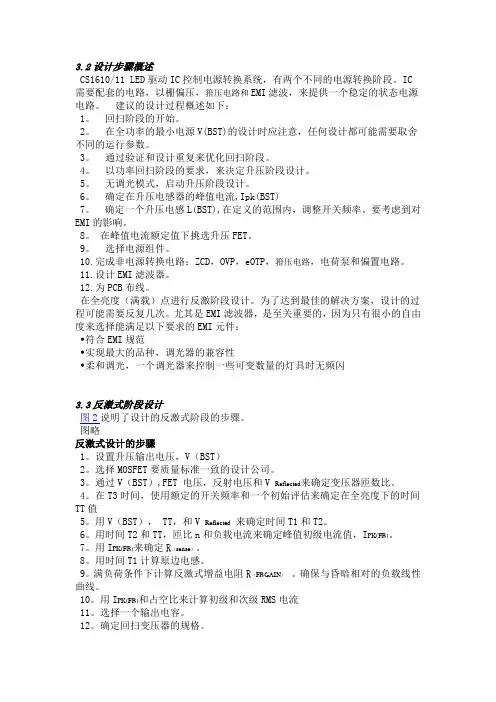
3.2设计步骤概述CS1610/11 LED驱动IC控制电源转换系统,有两个不同的电源转换阶段。
IC 需要配套的电路,以栅偏压,箝压电路和EMI滤波,来提供一个稳定的状态电源电路。
建议的设计过程概述如下:1。
回扫阶段的开始。
2。
在全功率的最小电源V(BST)的设计时应注意,任何设计都可能需要取舍不同的运行参数。
3。
通过验证和设计重复来优化回扫阶段。
4。
以功率回扫阶段的要求,来决定升压阶段设计。
5。
无调光模式,启动升压阶段设计。
6。
确定在升压电感器的峰值电流,Ipk(BST)7。
确定一个升压电感L(BST),在定义的范围内,调整开关频率。
要考虑到对EMI的影响。
8。
在峰值电流额定值下挑选升压FET。
9。
选择电源组件。
10.完成非电源转换电路:ZCD,OVP,eOTP,箝压电路,电荷泵和偏置电路。
11.设计EMI滤波器。
12.为PCB布线。
在全亮度(满载)点进行反激阶段设计。
为了达到最佳的解决方案,设计的过程可能需要反复几次。
尤其是EMI滤波器,是至关重要的,因为只有很小的自由度来选择能满足以下要求的EMI元件:•符合EMI规范•实现最大的品种,调光器的兼容性•柔和调光,一个调光器来控制一些可变数量的灯具时无频闪3.3反激式阶段设计图2说明了设计的反激式阶段的步骤。
图略反激式设计的步骤1。
设置升压输出电压,V(BST)2。
选择MOSFET要质量标准一致的设计公司。
3。
通过V(BST),FET 电压,反射电压和V来确定变压器匝数比。
4。
在T3时间,使用额定的开关频率和一个初始评估来确定在全亮度下的时间TT值5。
用V(BST), TT,和V来确定时间T1和T2。
6。
用时间T2和TT,匝比n和负载电流来确定峰值初级电流值,I。
7。
用I来确定R( )。
8。
用时间T1计算原边电感。
9。
满负荷条件下计算反激式增益电阻R( )。
确保与昏暗相对的负载线性曲线。
10。
用I和占空比来计算初级和次级RMS电流11。
选择一个输出电容。
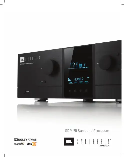
SDP-75 Surround ProcessorSETTING NEW STANDARDSThe JBL Synthesis ® SDP-75REVOLUTIONARY HARDWARE PLATFORMPowered by unrivalled processing capabilities and exclusive technologies, the SDP-75 opens the way to a whole new generation of luxury home cinema, achieving ultimate performance and sustainability within the fast moving home theater entertainment industry, now driven by 3D Audio and 4K Ultra High Definition video with High Dynamic Range (HDR) compatibility.The SDP-75 is available in 16, 24, and 32 channel versions. It also supports the latest HD Audio and Video formats including D-Cinema while offering 3D audio decoding options and delivering up to 32 discrete, uniquely-rendered channels of immersive audio content at an unprecedented level of quality, for a whole new listening experience, leaving the competition far behind. Our exclusive Anechoic EQ improves loudspeakers at higher frequencies than can be equalized with high-resolution based only on in-room measurements.The SDP-75 is Roon Ready, capable of up-mixing two-channel or multi-channel music from Roon via the built-in Auro Auro-matic, Dolby Atmos, or DTS:X algorithms.From the revolutionary hardware platform to the software environment, everything has been specified with no compromise to provide a unique user experience unmatched by any other product available.At the heart of this new generation of processor is a new approach to processing digital signals, based on a revolutionary hardware architecture that is highly scalable and easy to upgrade.Instead of traditionally using multiple DSP chips implemented in a complex and rigid architecture, a partnership between JBL Synthesis and Trinnov allowed us to develop a multi-purpose processing platform, based on a multi-core Intel computer processor to provide unrivalled processing capabilities.Used every day in demanding professional environments, this architecture meets the highest requirements in terms of reliability. Despite its extreme sophistication, the SDP-75 is easy to operate thanks to a unique user-friendly and self-explanatory web-based user interface.PARTNERSHIP FOR SUCCESSA partnership between JBL Synthesis and Trinnov in the development of the SDP-75 processor has laid the stage for the success of the SDP-75.With over 60+ years of audio experience JBL has become the choice of almost all top music and movie professionals in the industry. This experience has allowed JBL to release some of the most influential products being used today. Trinnov Audio brings years of experience building top of the line processors for numerous consumer and commercial applications. Their team of passionate audio engineers and professionals helps bring to life innovative solutions that are always improving the quality of sound.The Trinnov Optimizer provides automated multi-point Room EQ, with HARMAN optimization parameters and target responses from HARMAN X research.MAIN FEATURES• 16, 24, or 32 Channel Digital Audio Processor• Universal Spatial-Accurate 3D Audio playback• Roon Ready• 118 Digital and Analog Inputs and 80 audio Outputs• 7x HDMI 2.0a/HDCP 2.2 compliant inputs, individually configurable asHDMI 1.4b as desired for legacy sources• Full Matrix Input/Output• Setup Wizard• User-friendly, self-explanatory user interface• Built-in WiFi & UPnP/DLNA Compliant Digital Media Renderer• Wide choice of Remote OptionsHIGHLIGHTSAUDIO FORMATS• HDMI 2.0 compliant digital audio with 3D videopass-through• HD Audio Codecs: Dolby TrueHD, DTS-HDMaster Audio• 3D Audio Codecs: Dolby Atmos, Auro3D, DTS:X• LPCM Audio: 16-channels AES input compatiblewith Digital Cinema Servers• Dolby Atmos extraction of Dolby Atmos/7.1 AES/DCI Audio from Digital Cinema Servers• UPnP/DLNA renderer: WAV, AIFF, OGG, FLACup to 24 bits/192 kHzEXCLUSIVE TECHNOLOGIESAnechoic EQ for popular Revel and JBL Synthesis Loudspeakers• Provides high-resolution EQ that can only be achieved using anechoic measurementsNEXT GENERATION HARDWARE PLATFORM• Revolutionary architecture, scalable processing platform;• 64-bit floating point & 24-bit/192 kHz native processing;• Software-oriented upgrades provided over Internet, no need for DSP upgrade• Robust design, inspired from Professional Audio product linesEQUALIZERS• Automated Multi-point Room EQ utilizing the Trinnov Optimizer with custom HARMAN operating parameters• Simple drop-down loudspeaker selection• Exclusive HARMAN EQ Targets based uponindustry-leading HARMAN X researchAUDIO PROCESSING• Manual processing• Several layers of 31 bands Graphic EQ, gain,polarity and delay available for every channel• Comprehensive Processing latency control• Total delay given in meters/milliseconds/framesfor the listening point;• Adjustable global delay for accurate Lip Sync REMOTE MANAGEMENT• VNC Remote Control through the network from any smartphone, tablet or laptop• Web-based responsive interface• Automation via Telnet and RS232 protocols• Crestron, Savant, Control4, AMX, RTI and URC modules available• Built-in Gigabit Ethernet and WiFiPOWER• Dedicated linear power supply with toroidal transformer on the Analog audio circuit• Dedicated PSU/switch-mode power supply on the digital audio circuitSTATE-OF-THE-ART BASS MANAGEMENT• Easily set different high-pass and low-pass frequencies and slopes for each pair of speakers • Optionally bass manage very small surround speakers to the nearest speaker capable of lower frequency extension, which can then itself be crossed-over to the subwoofersCOMING SOON – FREE SOFTWARE UPGRADES IN 2019• IMAX Enhanced® to see and hear IMAX Enhanced media as the filmmaker intended• DTS:X Pro® with up to 32 uniquely-rendered DTS:X Pro channelsJBL SYNTHESIS SDP-75 SPECIFICATIONS Video Outputs 1 x HDMI, 1 x DVI, 1 x VGAUSB Ports 2 x USB 3.0, 2 x USB 2.0Ethernet 1 x RJ45 Gigabit, WiFi OnboardControllers PS/2 Keyboard and Mouse Additional Ports 1 x Parallel (unused), 1 x S/PDIF Digital Audio (unused), 1 x 3.5mm Audio (unused)Power Supply 110VAC 60Hz or 220VAC 50/60Hz Power Consumption 0.5W standby (EuP compliant) / 100W/450mA Maximum Dimensions (H x W x D) 6.1" x 16.9" x 15.9" (155mm x 430mm x 405mm)Weight 30.8 lb (14.5kg)Remote Control IR Remote Control Included, 12V Trigger Input/Output, iOS and Android Apps Available, Web-based UINetwork Control VNC Remote Control from Laptop/PC, Tablet, or Smartphone, IP Control (AMX, Crestron, and Savant Modules Available)Analog Audio Inputs 2 x XLR stereo, 3 x RCA stereo, 1 x 8-ch RCA multichannel, 1 x 3D MicrophoneDigital Audio Inputs 8 x HDMI multichannel, 1 x AES3 DB25 (8 or 16-channels) DCI-compliant, 2 x AES/EBU XLR stereo, 4 x S/PDIF Coaxial 7.1 PCM, 4 x S/PDIF Optical 7.1 PCM Analog Audio Outputs 16 x XLR multichannel, 4 x Balanced DB25 (channels 1-32), 1 x RCA stereoDigital Audio Outputs 2 x HDMI multichannel, Roon Ready via Ethernet, 1 x AES3 DB25 (8 or 16-channels), 1 x AES/EBU XLR stereo, 1 x S/PDIF Coaxial stereo, 1 x S/PDIF Optical stereo, 1 x AML Extension Link RJ45Inputs 7x HDMI 2.0a/HDCP 2.2 compliant inputs, individually configurable as HDMI 1.4b as desired for legacy sourcesOutputs 1 x HDMI 2.0a with HDCP 2.2, 1 x HDMI 1.4a, 1 x PC (VGA, DVI, HDMI)© 2019 Harman International Industries, Incorporated. All rights reserved. Features, specifications, and appearance are subject to change without notice.. Harman International Industries, Inc.8500 Balboa Blvd Northridge CA 91329+1 (888) 691-4171 JBL, JBL Synthesis, Lexicon, Logic 7 and the L7 logos are registered trademarks of Harman International Industries, Incorporated. TrueHD, Dolby Volume, Dolby, Dolby Digital Plus, Pro Logic, and the double-D symbol are registered trademarks of Dolby Laboratories, Inc. DTS, DTS-ES, DTS-HD Audio, Neo:6 and the DTS symbol are registered trademarks of DTS, Inc. HDMI, the HDMI logo and High-Definition Multimedia Interface are trademarks or registered trademarks of HDMI Licensing LLC. Macrovision is a registered trademark of Macrovision Corporation. All rights reserved. SACD is a trademark of Sony Corporation. Digital EX is a jointly developed technology of THX and Dolby Laboratories, and is a trademark of Dolby Laboratories. Used under authorization.Manufactured under license under U.S. Patents numbers 5956674; 5974380; 6226616; 6487535; 7212872; 7333929; 7392195; 7272567 and other worldwide patents issued and pending.。
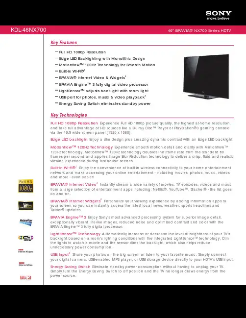
Key FeaturesFull HD 1080p ResolutionEdge LED Backlighting with Monolithic Design Motionflow™ 120Hz Technology for Smooth Motion Built-in Wi-Fi®1BRAVIA® Internet Video & Widgets 2BRAVIA Engine™ 3 fully digital video processorLightSensor™ adjusts backlight with room light USB port for photos, music & video playback 3 Energy Saving Switch eliminates standby power Key TechnologiesFull HD 1080p Resolution Experience Full HD 1080p picture quality, the highest at-home resolution,and take full advantage of HD sources like a Blu-ray Disc™ Player or PlayStation®3 gaming console via the 16:9 wide screen panel (1920 x 1080).Edge LED backlight Enjoy a slim design plus amazing dynamic contrast with an Edge LED backlight.Motionflow™ 120Hz Technology Experience smooth motion detail and clarity with Motionflow™120Hz technology. Motionflow™ 120Hz technology doubles the frame rate from the standard 60frames per second and applies Image Blur Reduction technology to deliver a crisp, fluid and realistic viewing experience during fast-action scenes.Built-In Wi-Fi® Enjoy the convenience of built-in wireless connectivity to your home entertainment network and make accessing your online entertainment - including movies, photos, music, videos and more - even easier!1 BRAVIA® Internet Video Instantly stream a wide variety of movies, TV episodes, videos and musicfrom a large selection of entertainment apps including: Netflix®, YouTube™, Slacker® - the list goes on and on.2 BRAVIA® Internet Widgets Personalize your viewing experience by adding information apps toyour screen so you can instantly access the latest local news, weather, sports headlines and Twitter® updates.2 BRAVIA Engine™3 Enjoy Sony's most advanced processing system for superior image detail,exceptionally vibrant, life-like images, reduced noise and optimized contrast and color with the BRAVIA Engine™ 3 fully digital processor.LightSensor™ Technology Automatically increase or decrease the level of brightness of your TV'sbacklight based on a room's lighting conditions with the integrated LightSensor™ technology. Dim the lights to watch a movie and the sensor dims the backlight, which also helps reduce unnecessary power consumption.USB Input Share your photos on the big screen or listen to your favorite music. Simply connectyour digital camera, USB-enabled MP3 player, or USB storage device directly to your HDTV's USB input.3 Energy Saving Switch Eliminate standby power consumption without having to unplug your TV.Simply turn the Energy Saving Switch to off position and the TV no longer draws energy from the power source.Sony Electronics Inc. • 16530 Via Esprillo • S an Diego, CA 92127 • 1.800.222.7669 • w Last Updated: 02/22/2010Please visit the Dealer Network for currentinformation at /dnFeaturesGeneralClosed Captions (CC): Analog, Digital Illuminated Sony Logo: Yes Finish (Surface Color): Black XMB: YesAudio Return Channel: Yes HDMI™ InstaPort: YesDisplayBacklight Type: LED Display Device: LCD Deep Black Panel: YesVideoVideo Processing: BRAVIA Engine 3™ TechnologyCineMotion® Reverse 3:2 Pulldown Technology: Yes Wide Mode: Normal, Zoom, Wide Zoom, Full (Full1-2 for PC), H Stretch Deep Color: Yes 3D Comb Filter: YesPhotoTV HD: YesMPEG Noise Reduction: Yes Auto Wide: Yes 4:3 Default: Yes24p True Cinema™ Technology: YesPicture Mode: Vivid, Standard, Custom, Cinema, Game-Standard, Game-Original, Graphics, Sports, Photo-Vivid, Photo-Standard, Photo-Original, Photo-Custom Advanced Contrast Enhancer (ACE): Yes Motionflow™ Technology: 120Hz Cinema Mode: YesLive Color™ Technology: YesAudioAuto SAP: 20FM/10AMAuto Mute (on no signal): YesSteady Sound® Automatic Volume Control: Yes Audio Out: Variable/Fixed Sony Original Surround: Yes Stereo System: MTS Dolby®: Dolby® DigitalAlternate Audio (Digital): yesSurround Effect: Cinema, Music, Live Sports, Game5.1 Channel Audio Out: YesSound Mode: Dynamic, Standard, Clear Voice, Custom5.1ch Through Out (Handycam): Yes Sound Enhancer: YesClear Voice: YesInvisible Speaker (w/Sound Elevation): YesConvenienceChannel Jump: YesMultiple Language Display: English, French, Spanish Info Banner: TV Guide on Screen, PSIP, XDS Sleep Timer: YesInput Skip: Automatic Channel Surf: YesChannel Block (with password): Yes Edit Channel Labels: Yes Label Inputs: YesOn/Off Timer: YesUSB Application(s): Photo Viewer (jpeg), Photo Viewer (RAW), Music Player (mp3), Video Player (AVCHD), Video Player (AVC), Video Player (MPEG4) Theatre Mode (Theatre Button): YesShow/Hide Channels: YesAuto Shut-off: YesBRAVIA® Sync™: Yes Parental Control: YesBRAVIA® Sync™ Menu Button: Yes (on Remote Control)On-Screen Display for External Input: Yes PIP (Picture in Picture): PC Input(HDMI)/TV Channel&CVBS Channel Labels: YesAuto Photo Mode: via HDMI, via DLNA, via USB On-Screen Clock: YesPicture Adjustments Lock: Yes White Balance: RGB Gain/BiasAuto Picture Setting w/HDMI™: Cinema, Sport, Music, Photo, Graphics, Game Internet Radio: YesScene Select: Auto, Cinema, Sports, Photo, Music, Game, Graphics, OFFTheatre Mode with Cinema Surround: Yes TV Guide On-Screen: YesStand Tilt: YesStand Tilt Range: 2position 0°/ Back 6° On-Screen Operating Instructions: Yes Favorites: YesPicture Frame Mode: Yes Quick Start: YesStand Swivel: YesStand Swivel Range: Left 20°/Right 20° Start Up Sony Logo Display: Yes USB Player: YesWireless LAN: Integrated Upward Style: YesNetworkDLNA: YesBRAVIA® Internet Video: Ready BRAVIA® Internet Widgets: Yes Photo MAP: YesSpecificationsDisplayViewing Angle (Right/Left): 178(89/89) Viewing Angle (Up/Down): 178(89/89) Dynamic Contrast Ratio: InfiniteScreen Size (measured diagonally): 46"Display Resolution: Full HD 1080(1920x1080) Aspect Ratio: 16:9TV SystemTuner (Cable): Clear QAMTuner (Terrestrial): ATSC™ / NTSC Channel Coverage: VHF: 2-13ch UHF: 14-69chCATV (analog): 1-135ch CATV (digital) : 1-135ch TV System (Analog): MNumber of Tuners (Digital): 1(Hybrid)TV System (Digital): ATSC Color System: NTSCVideoVideo Signal: 1080/60p (HDMI™ / COMPONENT), 1080/60i, 1080/24p (HDMI™ ONLY), 720/60p, 480/60p, 480/60iAudioAudio Power Output: 20W (10W x 2) Speakers (Total): 2Speaker Configuration: 2Inputs and OutputsComponent Video (Y/Pb/Pr ) Input(s): 1(1 Side) (Composite input common use))Composite Video Input(s): 2 ( 1 Side (Component input common use)/ 1 Rear) Digital Audio Output(s): Optical Digital Output - 1 (Rear)RF Connection Input(s): 1 (Rear)Analog Audio Input(s) (Total): 3 (2 Side/1 Rear) Audio Out: 1 (Rear)HDMI™ Connection(s) (Total): 4(2 Side/2 Rear) PC In (D-Sub) + Audio In (Stereo Mini): 1 (Side) USB 2.0: 1 (Side)HDMI™ PC Input: Yes (see owner's manual for supported timings) AC Power Input: 1 (Rear)Ethernet Connection(s): 1 (Rear)PowerPower Consumption (in Standby): 0.17W Power Requirements (voltage): AC 120V Power Requirements (frequency): 60HzPower Consumption (in Operation) max.: 129WPower Consumption (in Download Acquisition Mode): Less than 16 WRegulation and Standard ComplianceVESA® Hole Spacing Compatible: Yes VESA® Hole Pitch: 300x300 M6Service and Warranty InformationLimited Warranty Term: 1 Year Labor / 1 Year Parts Online Instruction Manual (Reference Book): YesEnergy Saving & EfficiencyLightSensor™ Technology: Yes Power Saving Modes: Yes Eco Settings: YesDynamic Backlight Control: Yes Backlight Off Mode: YesEstimated Annual Energy Consumption (kWh): 163.3kWh/year Idle TV Standby: YesEnergy Saving Switch: YesRecycled & Recyclable MaterialsProduct Materials: Recycled Carton (more than 40%)DimensionsWeight: 61.3 lbs. (27.8kg) with pedestal; 52.9 lbs. (24kg) without pedestal Measurements: 44.375 x 29 1/2 x 12 5/8 in (1127 x 748 x 320mm) with pedestal; 44.375 x 28 1/4 x 2.625 in (1127 x 716 x 64mm) without pedestalSupplied AccessoriesRemote Control (RM-YD037)Batteries (Type AAA x2) AC Power CordScrews (for pedestal, 4-screws)Table Top Stand (separate, pre-assembled)Optional AccessoriesWallmount Bracket (SU-WL700)UPC Code: 027*********1. Wireless router required (sold separately). Requires a compatible 802.11n access point. Some functionality may require Internet services.2. Connection speed of at least 2.5 Mbps recommended (10 Mbps for HD content). Video quality and picture size vary and are dependent upon broadband speed and delivery by content provider. Select content provided subject to change. Premium content may require additional fees and/or PC registration3. USB device must be formatted FAT-32.4. Dynamic contrast ratio compares the luminance of a 100 IRE (white) signal with that of a 0 IRE (black) signal. When the TV receives a 0 IRE signal the backlight is turned off and the luminance measurement is 0.00 cd/m . The resulting dynamic contrast ratio is infinite. © 2010 Sony Electronics Inc. All rights reserved. Reproduction in whole or in part without written permission is prohibited. Sony, BRAVIA, Motionflow, BRAVIA Engine, LightSensor, make.believe, and the Sony logo, Full HD 1080p logo and BRAVIA logo are trademarks of Sony. PlayStation is a trademark of Sony Computer Entertainment. Blu-ray Disc is atrademark. All other trademarks are trademarks of their respectiveowners. Features and specifications are subject to change without notice. Non-metric weights and measures are approximate and may vary.2。
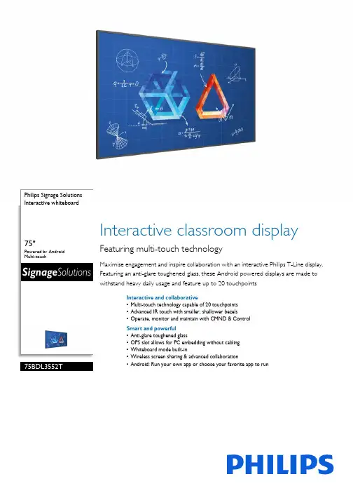
Philips Signage Solutions Interactive whiteboard75"Powered by Android Multi-touch75BDL3552TInteractive classroom displayFeaturing multi-touch technologyMaximise engagement and inspire collaboration with an interactive Philips T-Line display. Featuring an anti-glare toughened glass, these Android powered displays are made to withstand heavy daily usage and feature up to 20 touchpointsInteractive and collaborative•Multi-touch technology capable of 20 touchpoints •Advanced IR touch with smaller, shallower bezels•Operate, monitor and maintain with CMND & Control Smart and powerful•Anti-glare toughened glass•OPS slot allows for PC embedding without cabling •Whiteboard mode built-in•Wireless screen sharing & advanced collaboration•Android: Run your own app or choose your favorite app to runHighlightsMulti-touch technologyCreate a memorable interactive experience with up to 20 touchpoints at the same time. Perfect for collaborative and competitive applications, this display connects youraudience with any content - making it ideal for education, public venues, corporate,hospitality, and retail settings. The touch panel is HID compliant, providing true plug-and-play operation.CMND & ControlRun your display network over a local (LAN) connection. CMND & Control allows you to perform vital functions like controlling inputs and monitoring display status. Whether you're in charge of one screen or 100.Whiteboard mode built-inInspire agile collaboration with whiteboard mode. Simply activate this feature to turn your display into a blank canvas that can be drawn on by multiple users by hand or with dedicated display markers. Everything on screen can then be captured for easy printing or file sharing.OPS slotIntegrate a full-power PC or Android-powered CRD50 module directly into your Philips Professional Display. The OPS slot contains all the connections you need to run your slot-in solution, including a power supply.Wireless screen sharingDisplay four feeds on the one screen. Wireless screen sharing allows you to connect multipledevices at the same time for quick content switching when you need it. Use your existing Wi-Fi network to instantly and securely connect devices, or use our optional HDMI interact dongles to cast directly to the screen without needing to connect to your secured/protected network.Powered by AndroidWIth Android OS integrated into the display, you can work with the most developed OS on the planet and save your own app directly into the display. Or, choose from the large library of Android apps and play content from there. With the built-in scheduler, you can daypart your apps and content based on yourcustomer and time of day and with the auto orientation feature, showing content inportrait or landscape is as simple as turning thedisplay.Issue date 2021-09-19Version: 11.0.112 NC: 8670 001 66458EAN: 87 12581 76597 2© 2021 Koninklijke Philips N.V.All Rights reserved.Specifications are subject to change without notice. Trademarks are the property of Koninklijke Philips N.V. or their respective owners.SpecificationsPicture/Display•Diagonal screen size: 74.5 inch / 189.3 cm •Panel resolution: 3840 x 2160•Optimum resolution: 3840 x 2160 @ 60Hz •Brightness: 420 cd/m²•Contrast ratio (typical): 1200:1•Dynamic contrast ratio: 500,000:1•Surface treatment: Anti-Glare coating •Aspect ratio: 16:9•Response time (typical): 9 ms •Pixel pitch: 0.4296 x 0.4296 mm •Display colors: 1.07Billon•Viewing angle (H / V): 178 / 178 degree•Picture enhancement: 3/2 - 2/2 motion pull down, 3D Combfilter, Motion compens. deinterlacing, Progressive scan, 3D MA deinterlacing, Dynamic contrast enhancement •Panel technology: IPS•Operating system: Android 9Interactivity•Multi-touch technology: Advanced infrared touch •Touch points: 20 simultaneous touch points •Plug and play: HID compliant•Protection glass: Anti-Glare, Tempered safety glassConnectivity•Video input: Display Port1.2 (x1), DVI-I (x 1), HDMI 2.0 (x4), USB 2.0 (x2), USB 3.0 (x2), USB-C •Audio input: 3.5mm Jack (x1)•Audio output: 3.5mm Jack (x2)•Other connections: OPS, micro SD•External control: IR (in/out) 3.5 mm jack, RJ45, RS232C (in/out) 2.5 mm jack•Video output: DisplayPort 1.2 (x1), DVI - D (x1), HDMI 2.0 (x1), USB 2.0 (x2)Supported Display Resolution•Computer formats Resolution Refresh rate 1600 x 1200 60Hz 1360 x 768 60Hz 1024x768 60,70Hz 1152 x 864 60, 70, 75Hz 1152 x 900 66Hz 1280 x 720 60,70Hz 1280 x 768 60Hz, 75Hz 1280 x 800 60,75Hz 1280 x 960 60Hz1280x1024 60,67,75Hz 1366 x 768 60Hz 1400 x 1050 60, 75Hz 1440 x 1050 60Hz 1440 x 900 60, 75Hz 1600 x 900 60Hz 1680 x 1050 60Hz 1920 x 1080 60Hz 1920 x 1200 60Hz3840 x 2160 24,25,30,60Hz 640 x 350 70Hz640 x 480 60, 67, 72, 75Hz 800 x 600 56, 60, 72, 75Hz 832 x 624 75Hz 848 x 480 60Hz 960x72075Hz •Video formats Resolution Refresh rate 1080p 50, 60Hz 720p 50, 60Hz 1080i 50, 60Hz 480p 60Hz 4K x 2K 576p 50Hz 720p60HzConvenience•Placement: Landscape (18/7)•Signal loop through: IR Loopthrough, DisplayPort, RS232•Network controllable: RS232, RJ45•Picture performance: Advanced color control •Screen saving functions: Pixel Shift, Low Brightness •Keyboard control: Hidden, Lockable •Remote control signal: Lockable•Energy saving functions: Smart Power •Other convenience: Carrying handles •Ease of installation: Smart InsertDimensions•Bezel width: 16.30 mm(even)•Set dimensions (W x H x D):1715.50 x 993.70 x 80.8mm(D@wall mount) / 108.7(D@speaker cover) mm•Set dimensions in inch (W x H x D):67.54 x 39.12 x 3.18(D@wall mount) /4.28 (D@speaker cover) inch•VESA Mount: 600(H)x400(V) mm, M8•Product weight: 53.0 kg•Product weight (lb): 116.85 lb•Smart Insert mount: 100mm x 100mm, 6xM4L6Sound•Built-in speakers: 2 x 20W RMSOperating conditions•Temperature range (operation): 0 ~ 40 °C •Relative humidity: 20 ~ 80%(Operational),5 - 95%(Storage) %•MTBF: 30,000 hour(s)•Altitude: 0 ~ 3000 m•Temperature range (storage): -20 ~ 60 °CPower•Mains power: 100 ~ 240 VAC, 50/60Hz •Standby power consumption: <0.5W •Consumption (Typical): 190 W•Power Saving Features: Smart Power •Consumption (Max): 380 W •Energy Label Class: GAccessories•Included accessories: AC Power Cord, RS232 cable, Remote Control, Batteries for remote control, Quick start guide, HDMI cable, IR sensor cable (1.8M)•Included Accessories: Cleaning cloth (x1), DVI-D cable (1.8m ), M2 Screw (x2), M3 screw (x2), Philips logo (x1), RS232 daisy-chain cable, Touch Pen (x2), Touch USB (x1), USB Cover (x1)•Optional accessories: Cast to dongleMiscellaneous•On-Screen Display Languages: Arabic, English, French, German, Italian, Japanese, Polish, Spanish, Turkish, Russian, Simplified Chinese, Traditional Chinese, Portuguese, Danish, Dutch, Finnish, Norwegian, Swedish•Regulatory approvals: CE, BSMI, CB, EMF, ETL, FCC, Class A, PSB, RoHS, EAC •Warranty: 3 year warrantyMultimedia Applications•USB Playback Audio: AAC, M4A, MP3, WMA •USB Playback Picture: BMP, JPEG, JPG, PNG •USB Playback Video: ASF, AVI, DAT, FLV, MKV, MP4, MPG, TS, VOB, MPEG, WEBM, WMVInternal Player•CPU:MTK5680•Memory:4GB RAM •Storage: 32 GB eMMc•Wifi: AP(WC0SR2511-88112BU), STA(WCT5GM2511MT7668AU)•GPU: DDR4 4GB。
ADIADV7513165MHzHDMI视频解决方案HDMIHDMIHDMI发送器,数字视频接口包括一个HDMI v1.4/DVI v1.0兼容的发送器,支持高达1080p和 XGA的所有的HDTV格式,包括3D视频,还支持x.v.Color高比特率(HBR)音频以及可编程AVI InfoFrame,工作电压 1.8V-3.3V,主要用在游戏控制台,PC,DVD播放和记录,数字STB,A/V接收器.本文介绍了ADV7513主要特性, 功能方框图和EVAL-ADV7612-7511视频评估板主要特性,方框图,电路图以及PCB布局图.The ADV7513 is a 165 MHz, High-Definition Multimedia Interface (HDMI®) transmitter that is ideal for DVD players/ recorders, digital set-top boxes, A/V receivers, gaming consoles, and PCs.The digital video interface contains an HDMI v1.4/DVI v1.0-compatible transmitter and supports all HDTV formats. The ADV7513 supports HDMI v1.4-specific features, including 3D video. The ADV7513 also supports x.v.Color™, high bit rate (HBR) audio, and the programmable auxiliary video information (AVI) InfoFrame features. With the inclusion of HDCP, the ADV7513 allows the secure transmission of protected content as specified by the HDCP v1.4 protocol.The ADV7513 supports both S/PDIF and 8-channel I2S audio. Its high fidelity 8-channel I2S interface can transmit either stereo or 7.1 surround audio up to 768 kHz. The S/PDIF interface can carry compressed audio, including Dolby® Digital, DTS®, and THX®. Fabricated in an advanced CMOS process, the ADV7513 is provided in a 64-lead LQFP surface-mount plastic package with exposed pad and is specified over the −25℃ to +85℃ temperature range.ADV7513主要特性:GeneralIncorporates HDMI v1.4 features, including 3D video support165 MHz supports all video formats up to 1080p and UXGASupports gamut metadata packet transmissionIntegrated CEC buffer/controllerCompatible with DVI v1.0 and HDCP v1.4Video/audio inputs accept logic levels from 1.8 V to 3.3 VDigital video3D video readyProgrammable, 2-way color space converterSupports RGB, YCbCr, and DDRSupports ITU-656-based embedded syncsAutomatic input video format timing detection (CEA-861-E)Digital audioSupports standard S/PDIF for stereo linear pulse code modulation (LPCM) or compressed audio up to 192 kHzHigh bit rate (HBR) audio8-channel uncompressed LPCM I2S audio up to 192 kHzSpecial features for easy system design5 V tolerant I2C and Hot Plug™ detect (HPD) I/Os, no extra device neededNo audio master clock needed for supporting S/PDIF and I2SOn-chip MPU with I2C master performs HDCP operations and EDID reading operationsOn-chip MPU reports HDMI events through interrupts and registersADV7513应用:Gaming consolesPCsDVD players and recordersDigital set-top boxesA/V receivers图 1.ADV7513功能方框图EVAL-ADV7612-7511视频评估板The Advantiv® EVAL-ADV7612-7511 video evaluation board (AVEB) is a low cost solution for evaluating the performance of the ADV7612 HDMI receiver and/or the ADV7511 HDMI transmitter.The evaluation board provides a Blackfin® ADSP-BF524 processor for system control.The ADSP-BF524 offers the potential to process audio (no audio software is included).The evaluation board includes software (firmware) that provides a serial command interface to control the board’s functionality.This evaluation board is available in two options.With HDCP support (EVAL-ADV7612-7511), available only to licensees of HDCPWithout HDCP support (EVAL-ADV7612-7511P)EVAL-ADV7612-7511视频评估板主要特性:2 HDMI inputs, 1 HDMI outputPC communication via RS-232 or USB interfaceJumperable signal paths for audio and video (jumpers can be removed and signals connected in a differentmanner)EQUIPMENT NEEDEDComputer with RS-232 (or USB) I/O to accomplish the following:Send scripts to the board’s command line interfaceSend commands to the board’s repeater software and view software outputControl the board via Advantiv video evaluation software (AVES) applicationUpdate the board’s firmware (if desired or necessary)图 2.EVAL-ADV7612-7511视频评估板外形图图3.EVAL-ADV7612-7511视频评估板框图图 4.EVAL-ADV7612-7511视频评估板电路图(1)图5.EVAL-ADV7612-7511视频评估板电路图(2)图6.EVAL-ADV7612-7511视频评估板电路图(3)图7.EVAL-ADV7612-7511视频评估板电路图(4)图8.EVAL-ADV7612-7511视频评估板电路图(5)图9.EVAL-ADV7612-7511视频评估板电路图(6)图10.EVAL-ADV7612-7511视频评估板电路图(7)图11.EVAL-ADV7612-7511视频评估板电路图(8)图12.EVAL-ADV7612-7511视频评估板电路图(9)图13.EVAL-ADV7612-7511视频评估板电路图(10)图14.EVAL-ADV7612-7511视频评估板电路图(11)图15.EVAL-ADV7612-7511视频评估板电路图(12)图16.EVAL-ADV7612-7511视频评估板PCB布局图详情请见:/static/imported-files/data_sheets/ADV7513.pdf和/static/imported-files/user_guides/UG-295.pdf以及/servlet/JiveServlet/download/1713-12-5517/EVAL-ADV7612-7511_rev0p1_schems.pdf。
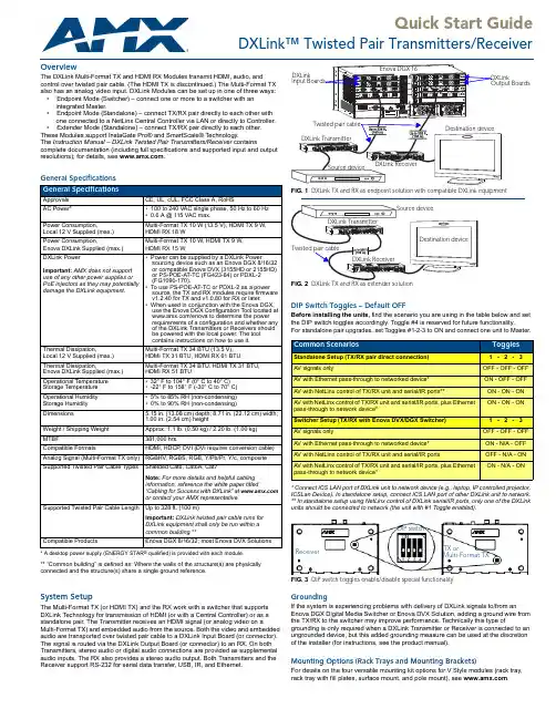
Quick Start GuideDXLink™ Twisted Pair Transmitters/ReceiverOverviewThe DXLink Multi-Format TX and HDMI RX Modules transmit HDMI, audio, andcontrol over twisted pair cable. (The HDMI TX is discontinued.) The Multi-Format TXalso has an analog video input. DXLink Modules can be set up in one of three ways:•Endpoint Mode (Switcher) – connect one or more to a switcher with anintegrated Master.•Endpoint Mode (Standalone) – connect TX/RX pair directly to each other withone connected to a NetLinx Central Controller via LAN or directly to Controller.•Extender Mode (Standalone) – connect TX/RX pair directly to each other.These Modules support InstaGate Pro® and SmartScale® Technology.The Instruction Manual – DXLink Twisted Pair Transmitters/Receiver containscomplete documentation (including full specifications and supported input and outputresolutions); for details, see .General Specifications* A desktop power supply (ENERGY STAR® qualified) is provided with each module.** “Common building” is defined as: Where the walls of the structure(s) are physicallyconnected and the structure(s) share a single ground reference.System SetupThe Multi-Format TX (or HDMI TX) and the RX work with a switcher that supportsDXLink Technology for transmission of HDMI (or with a Central Controller) or as astandalone pair. The Transmitter receives an HDMI signal (or analog video on aMulti-Format TX) and embedded audio from the source. Both the video and embeddedaudio are transported over twisted pair cable to a DXLink Input Board (or connector).The signal is routed via the DXLink Output Board (or connector) to an RX. On bothTransmitters, stereo audio or digital audio connections are provided as supplementalaudio inputs. The RX also provides a stereo audio output. Both Transmitters and theReceiver support RS-232 for serial data transfer, USB, IR, and Ethernet.DIP Switch Toggles – Default OFFBefore installing the units, find the scenario you are using in the table below and setthe DIP switch toggles accordingly. Toggle #4 is reserved for future functionality.For standalone pair upgrades, set Toggles #1-2-3 to ON and connect one unit to Master.* Connect ICS LAN port of DXLink unit to network device (e.g., laptop, IP controlled projector,ICSLan Device). In standalone setup, connect ICS LAN port of other DXLink unit to network.** In standalone setup using NetLinx control of DXLink serial/IR ports, only one of the DXLinkunits should be connected to network (the unit with #1 Toggle enabled).GroundingIf the system is experiencing problems with delivery of DXLink signals to/from anEnova DGX Digital Media Switcher or Enova DVX Solution, adding a ground wire fromthe TX/RX to the switcher may improve performance. Technically this type ofgrounding is only required when a DXLink Transmitter or Receiver is connected to anungrounded device, but this added grounding measure can be used at the discretionof the installer (for instructions, see the product manual).Mounting Options (Rack Trays and Mounting Brackets)For details on the four versatile mounting kit options for V Style modules (rack tray,rack tray with fill plates, surface mount, and pole mount), see . General SpecificationsApprovals CE, UL, cUL, FCC Class A, RoHSAC Power*•100 to 240 VAC single phase, 50 Hz to 60 Hz•0.6 A @ 115 VAC max.Power Consumption,Local 12 V Supplied (max.)Multi-Format TX 10 W (13.5 V), HDMI TX 9 W,HDMI RX 18 WPower Consumption,Enova DXLink Supplied (max.)Multi-Format TX 10 W, HDMI TX 9 W,HDMI RX 15 WDXLink PowerImportant:AMX does not supportuse of any other power supplies orPoE injectors as they may potentiallydamage the DXLink equipment.•Power can be supplied by a DXLink Powersourcing device such as an Enova DGX 8/16/32or compatible Enova DVX (3155HD or 2155HD)or PS-POE-AT-TC (FG423-84) or PDXL-2(FG1090-170).•To use PS-POE-AT-TC or PDXL-2 as a powersource, the TX and RX modules require firmwarev1.2.40 for TX and v1.0.80 for RX or later.•When used in conjunction with the Enova DGX,use the Enova DGX Configuration Tool located at/enova to determine the powerrequirements of a configuration and whether anyof the DXLink Transmitters or Receivers shouldbe powered with the local power. The toolcontains instructions on how to use it.Thermal Dissipation,Local 12 V Supplied (max.)Multi-Format TX 34 BTU (13.5 V),HDMI TX 31 BTU, HDMI RX 61 BTUThermal Dissipation,Enova DXLink Supplied (max.)Multi-Format TX 34 BTU, HDMI TX 31 BTU,HDMI RX 51 BTUOperational TemperatureStorage Temperature•32° F to 104° F (0° C to 40° C)•-22° F to 158° F (-30° C to 70° C)Operational HumidityStorage Humidity•5% to 85% RH (non-condensing)•0% to 90% RH (non-condensing)Dimensions 5.15 in. (13.08 cm) depth; 8.71 in. (22.12 cm) width;1.00 in. (2.54 cm) heightWeight / Shipping Weight Approx. 1.1 lb. (0.50 kg) / 2.20 lb. (1.00 kg)MTBF381,000 hrs.Compatible Formats HDMI, HDCP, DVI (DVI requires conversion cable)Analog Signal (Multi-Format TX only)RGBHV, RGBS, RGB, Y/Pb/Pr, Y/c, compositeSupported Twisted Pair Cable Types Shielded Cat6, Cat6A, Cat7Note:For more details and helpful cablinginformation, reference the white paper titled“Cabling for Success with DXLink” at or contact your AMX representative.Supported Twisted Pair Cable Length Up to 328 ft. (100 m)Important: DXLink twisted pair cable runs forDXLink equipment shall only be run within acommon building.**Compatible Products Enova DGX 8/16/32; most Enova DVX SolutionsFIG. 1 DXLink TX and RX as endpoint solution with compatible DXLink equipmentCommon Scenarios TogglesStandalone Setup (TX/RX pair direct connection) 1 - 2 - 3AV signals only OFF - OFF - OFFAV with Ethernet pass-through to networked device*ON - OFF - OFFAV with NetLinx control of TX/RX unit and serial/IR ports**ON - ON - ONAV with NetLinx control of TX/RX unit and serial/IR ports, plus Ethernetpass-through to network device*ON - ON - ONSwitcher Setup (TX/RX with Enova DVX/DGX Switcher) 1 - 2 - 3AV signals only OFF - OFF - OFFAV with Ethernet pass-through to networked device*ON - N/A - OFFAV with NetLinx control of TX/RX unit and serial/IR ports OFF - N/A - ONAV with NetLinx control of TX/RX unit and serial/IR ports, plus Ethernetpass-through to network device*ON - N/A - ONFIG. 3 DIP switch toggles enable/disable special functionalityReceiver TX orDIP switchMulti-Format TXFor warranty information, see .08/2013©2013 AMX. All rights reserved. AMX and the AMX logo are registered trademarks of AMX.AMX reserves the right to alter specifications without notice at any time.3000 RESEARCH DRIVE, RICHARDSON, TX 75082 • 800.222.0193 • fax 469.624.7153 • technical support 800.932.6993 • REV: D 93-1010-300REV: HTwisted Pair Cable Pinouts and RJ-45 LEDsThe DXLink and ICS LAN 10/100 ports both use twisted pair cable. FIG.4 shows twoAttaching Signal, Transport, and Control CablesImportant Cabling Considerations:•Do not use the RJ-45 connector labeled “DXLink” for connecting to a standard Ethernet Network. The connector is used for signal transport.•Do not create a network (Ethernet) loop. A network loop is created when the enclosure and one or more of its DXLink Modules are connected to a common LAN (or a standalone pair when both endpoints connect to the same network).•DXLink cable runs for DXLink equipment should be within a common building. To attach signal, transport, and control cables to a Transmitter:1.Set DIP switch toggles if necessary (for settings, see the previous page).2.Multi-Format TX only – Attach HD-15 cable from source to Video In connector.3.HDMI In – Attach an HDMI cable from the source to the HDMI In connector.*4.DXLink connector – Attach a twisted pair cable to the DXLink output and to aDXLink input connector on the switcher (or on the RX for a standalone pair).5.Stereo Audio In jack (optional) – Insert analog audio cable from source into jack.6.Digital Audio In jack (optional) – Insert a S/PDIF plug on the digital audio cablefrom the source into the jack (see audio precedence table in next column).7.ICS LAN10/100 port (optional) – Attach twisted pair cable from this port to LAN. * DVI cable can be used via a cable adapter; however, advanced audio support from HDMI will not be available.To attach signal, transport, and control cables to the Receiver:1.Set DIP switch toggles if necessary (for settings, see previous page).2.DXLink input connector – Attach a twisted pair cable from the DXLink outputconnector on the switcher (or on a TX) to the DXLink input.3.HDMI Out – Attach HDMI cable from this port to the destination.4.Stereo Audio Out jack (optional) – Connect an analog audio cable from this portto the destination.Applying PowerCaution: If a desktop power supply is used to power the unit, it must be the one provided, which must not be altered in any way. Power can also come from PoE injector PS-POE-AT-TC (FG423-84). AMX does not support use of any other power supplies or PoE injectors, as they may potentially damage the DXLink equipment. Local power takes precedence over DXLink power (via DXLink port) from switcher. Important: If TXs/RXs are powered from an Enova DGX 8/16/32, use the Enova DGX Configuration Tool at /enova to calculate the power draw.To apply power to the Transmitter and Receiver:1.Plug the cord from the desktop power supply (provided) into the power jack onrear of the Transmitter (2.1 mm DC jack for 12 V local power).2.Plug the desktop power supply into an AC external power source. The PowerLED on the front of the Transmitter illuminates green, indicating a ready state.3.Repeat Steps 1 and 2 for the Receiver.This table shows LED states on initial power up. If not normal, check connections.* At power up, the RX defaults to Auto. Press the Scaling button to change the mode.IP Addressing ModesDHCP Mode (enabled when #3 Toggle is flipped ON)In DHCP Mode, the Module attempts to get a DHCP lease (consisting of anIP address, gateway, and other network parameters). If the attempt fails, the Moduleconfigures itself for a link-local address, but periodically re-tries DHCP and re-assignsthe IP to a valid DHCP grant if successful. At any time, if the Module determines thatits IP address has changed, it will disconnect and reconnect to the Master.Static IP Mode (set with ID button or Telnet command)With #3 Toggle set to ON, press ID for 10 seconds to assign address of 192.168.1.2or use a Telnet command to set unit to Static IP Mode (see the Instruction Manual).RS-232 Serial Data (Optional)The 232 port label is relative to data flow. Data enters at the RX label on theTransmitter, is sent via a DXLink cable through the switcher, and leaves at theTX label on the Receiver. Flow is vice versa from the Receiver to the Transmitter.The RS-232 pinout for all DXLink Modules is “TXD - RXD - Ground.”To wire the 232 port for serial data transfer:1.Wire the RS-232 connectors according to pinout above connectors.IR Control (Optional)The IR Receiver connects to the IR RX port on the Transmitter and the IR Emitterconnects to the IR TX port on the Receiver or vice versa, depending on theinstallation. The signal is sent via DXLink cable through the switcher. When aTransmitter and Receiver are used as a standalone pair, IR control acts as apass-through.USB Host and Keyboard/Mouse Ports (Rear)If needed, the Host (USB-B) port on the TX and the K/M port (USB-A) on the RXprovide HID support for a keyboard, mouse, and HUB.Program Port (Front)This USB mini-B port on the Transmitters supports DGX Configuration Software forprogramming a customer VGA EDID.ID Button (Front)The ID button on the front can be used to toggle between static and DHCP IPaddressing, assign a device address, reset the factory defaults, and restore thefactory firmware image (for details, see the Instruction Manual).Additional Information Covered in Instruction ManualFor information on the following, see the Instruction Manual – DXLink Twisted PairTransmitters/Receiver at :•Audio precedence; pinouts for VGA, component, S-Video, and composite•NetLinx control and programming commands; Telnet commands•IR file transfers; upgrading firmware image; restoring factory default settings FIG. 5 RJ-45 portsGreen LEDOn - Link status is activeOff - Link status is not activeIndicator LEDs Normal Power Up IndicatesPower Green Power is appliedDigital Video and AudioGreen Video and HDMI embeddedaudio are presentMulti-Format - C, Y/CY/PB/PR, RGBRGBHV, RGBSGreen or Off(only one of the threecan be green at a time)Corresponding signal ispresentRX - Scaling: Bypass/Auto/Manual One green, two off Current scaling mode*IR TX / IR RX Red / Yellow IR activity232 (Serial) TX / 232 (Serial) RX Red / Yellow Serial activityNetLinx Link/Act Green(Blinking = #3 Toggle OFF)Active LAN connection to anAMX NetworkNetLinx Status Green LAN activityCEC OFF Not currently supportedUSB Yellow Connected to deviceFIG. 9 IR External IR Receiver Module (left) and CC-NIRC NetLinx IR Emitter cable (right)FG-IR03FG10-000-11(not included)。

Xitanium Outdoor Essential Programmable Low Voltage LED DriversXi EP LV 150W 2.0-5.0A WL I1759290 033 92880Xitanium Essential Programmable (EP) LED drivers are designed for maximum reliability and flexibility, making it a preferred choice for different Outdoor applications. The key feature AOC (Adjustable Output Current ) can be programmed with the new e-set tool, a simple and fast way to configure the driver without the need to power on the driver and without the need for any software configuration. Xitanium EP Low Voltage (LV) drivers are specifically designed for low voltage o utdoor applications. Having high surge immunity, these durable, independently housed drivers deliver consistent, high performance to luminaires. It is an ideal solution for OEMs who need reliable, adjustable output current in a rugged independent form factor.Benefits•Low voltage/high current output fits low voltage o utdoor applications •AOC (Adjustable Output Current) gives full flexibility to output different currents to spec-in different projects •Compact housing saves luminaire space•Easy adjustment of outputcurrent/voltage saves time and labor cost•Robust design offers peace of mind and saves maintenance cost •IP rated housing allows use in a non-fully sealed gearboxFeatures•100-277V input voltage •Low voltage/high current output •Adjustable Output Current (AOC)•Compact housing dimensions•Digital way to adjust output current called e-set tool •Robust specifications for moisture, vibration, and temperature protection •IP67Application•Road and street lighting •Area and flood lighting •Tunnel lighting •High-bay lightingJanuary 2022Electrical input dataSpecification item Value Unit ConditionRated input voltage range200...254V ac Performance rangeRated input voltage230V acRated input frequency range47...63Hz Performance rangeRated input current0.71A@ rated output power @ rated input voltageMax. input current0.9A@ rated output power @ minimum performance input voltage Rated input power163W@ rated output power @ rated input voltagePower factor0.95@ rated output power @ rated input voltageTotal harmonic distortion10%@ rated output power @ rated input voltageEfficiency91%@ratedoutputpower@************************** Input voltage AC range85...305V ac Operational rangeInput frequency AC range45...66Hz Operational rangeIsolation input to output DoubleElectrical output dataSpecification item Value Unit ConditionRegulation method Constant CurrentOutput voltage24...50V dcOutput voltage max.60V Maximum output voltage (rms)Output current 2...5AOutput current min programmable2000mAOutput current tolerance ±5%At max. output currentt, Ta=25°COutput current ripple LF≤ 5%Ripple = peak / average, < 1kHzOutput current ripple HF≤ 5%Output P st LM≤ 0.1In entire operating windowOutput SVM≤ 0.1In entire operating windowOutput power48...150W Rated output power is 150WElectrical data controls inputSpecification item Value Unit ConditionControl method FixedWiring and ConnectionsSpecification item Value Unit TypeInput wire cross-section 1 / 17mm2 / AWG3x 1.0mm2 stranded wires, waterproof cable Output wire cross-section 1 / 17mm2 / AWG2x 1.0mm2 stranded wires, waterproof cable Maximum cable length2m Total length of wiring including LED module, one wayInsulationInsulation per IEC61347-1Input Output GroundInput Double BasicOutput Double BasicGround Basic BasicDimensions and weightSpecification item Value Unit Tolerance (mm)Length (A1)175mm± 2Mounting hole distance (A2)164mm± 2Length (A3)152.5mm± 2Width (B1)67mm± 1Width (B2)52.5mm± 1Width (B3)34mm± 1Height (C1)40mm± 1Mounting hole diameter (D1)4mm± 0.3Input cable length (E1)450mm± 30Output cable length (E2)450mm± 30Weight715gramLogistical dataSpecification item ValueProduct name Xi EP LV 150W 2.0-5.0A WL I175Logistic code 12NC9290 033 92880Pieces per box12Operational temperatures and humiditySpecification item Value Unit ConditionAmbient temperature-40...+55ºC Higher ambient temperature allowed as long as Tcase-max is notexceededTcase-max85ºC Maximum temperature measured at T case-pointTcase-life75ºC Measured at T case-pointRelative humidity10...90%Non-condensingLifetimeSpecification item Value Unit ConditionDriver lifetime50,000hours Measured temperature at Tcase-point is Tcase-max. Maximumfailures = 10%Storage temperature and humiditySpecification item Value Unit ConditionAmbient temperature-40...+80ºCRelative humidity 5...95%Non-condensingProgrammable featuresSpecification item Available Default setting ConditionSet Adjustable Output Current (AOC)3000 mAFeaturesSpecification item Value ConditionOpen load protection Yes Automatic recoveringShort circuit protection Yes Automatic recoveringOver power protection Yes Automatic recoveringHot wiring NoSuitable for fixtures with protection class I per IEC60598Overtemperature protection Yes Automatic recovering, refer to thermal guard curveInrush currentSpecification item Value Unit ConditionInrush current71A Input voltage 230VInrush peak width212µs Input voltage 230 V, measured at 50% heightDrivers / MCB 16A type B≤ 5pcs Indicative value at 230VPlease refer to the driver design in guide if you use other MCB-types.Driver touch current / protective conductor currentSpecification item Value Unit ConditionTypical Protective Conductor Current (ins. Class I)0.7mA rms Acc. IEC60598-1. LED module contribution not includedSurge immunitySpecification item Value Unit ConditionMains surge immunity (diff. mode)6kV Acc. IEC61000-4-5. 2 Ohm, 1.2/50us, 8/20usMains surge immunity (comm. mode)6kV Acc.IEC61000-4-5. 12 Ohm 1.2/50us,8/20usApplication InfoSpecification item ValueApproval marks and Certifications CB / CCC / CE / ENEC / RCM / SELV / UKCAIngress Protection classification (IP)67Application OutdoorMounting Type IndependentGraphs Operating windowThermal GuardMains GuardPower factor versus output powerEfficiency versus output powerTHD versus output power©2022 Signify Holding, IBRS 10461, 5600 VB, NL. All rights reserved.UK importer address: Signify Commercial UK Limited, 3, Guildford Business Park, GU2 8XG.The information provided herein is subject to change without notice. Signify does not give any representation or warranty as to the accuracy or completeness of the information included herein and shall not be liable for any action in reliance thereon. The information presented in this document is not intended as any commercial offer and does not form part of any quotation or contract, unless otherwise agreed by Signify.Philips and the Philips Shield Emblem are registered trademarks of Koninklijke Philips N.V. All other trademarks are owned by Signify Holding or their respective owners.Date of release: January 5, 2022 v1/oem。
AG71113to 1 HDMI/DVI/DisplayPort Dual-mode SwitchData Sheet V1.03 to 1 HDMI/DVI/DP++ Switch Change HistoryVersion Date Notes1.02016/12/22First ReleaseCopyrightCopyright© 2016 Algoltek, Inc. All rights reserved. The contents of these materials contain proprietary and confidential information (including trade secrets, copyright, and other Intellectual Property interests) of Algoltek, Inc. or its affiliates. All rights are reserved and contents, (in whole or in part) may not be reproduced, downloaded, disseminated, published, or transferred in any form or by any means, except with the prior written permission of Algoltek, Inc. or its affiliates.3 to 1 HDMI/DVI/DP++ SwitchIndexFeatures ........................................................................................................................................ - 1 - Process and Packaging ................................................................................................................. - 1 - Applications .................................................................................................................................. - 1 - General Description ..................................................................................................................... - 1 - 1. System Block and Functional Description ................................................................................ - 2 - PIN Assignment ........................................................................................................................ - 3 - PIN Description ......................................................................................................................... - 4 - 2. Electrical Characteristics .......................................................................................................... - 5 - Absolute Maximum Rating ....................................................................................................... - 5 - Normal Operating Conditions .................................................................................................. - 6 - I/O Specification ....................................................................................................................... - 6 - 3. Packing and Marking Specification .......................................................................................... - 7 - Marking .................................................................................................................................... - 7 - Package Drawing ...................................................................................................................... - 8 - LQFP-EP 48L ...................................................................................................................... - 8 - QFN 48L ............................................................................................................................ - 9 - 4. References .............................................................................................................................. - 10 -3 to 1 HDMI/DVI/DP++ SwitchList of FigureFigure 1 Application for 3 to 1 HDMI/DP++ Switch ............................................................. - 2 - Figure 2 System Block Diagram ........................................................................................... - 2 - Figure 3 PIN Assignment ..................................................................................................... - 3 - Figure 4 Marking ................................................................................................................. - 7 - Figure 5 LQFP-EP 48L Package Drawing ............................................................................... - 8 - Figure 6 QFN 48L Package Drawing ..................................................................................... - 9 -List of TableTable 1 Describes the IP related IO ports ............................................................................ - 5 - Table 2 Absolute Maximum Rating ...................................................................................... - 5 - Table 3 Normal Operating Conditions ................................................................................. - 6 - Table 4 I/O Specification ...................................................................................................... - 6 -3 to 1 HDMI/DVI/DP++ Switch●Implement auto equalization design for supportingFeatures●Single voltage supply 3.15V ~ 5.5V● Support both AC coupled and DC coupled inputs ● Support HDMI, DVI and DisplayPort input ● Compatible to HDMI 1.4b specification●Compatible to DisplayPort Dual-Mode Standard version 1.1 ●Maximum TMDS throughput up to 3.4Gbps per lane (Total 10.2 Gbps) ●Maximum pixel clock rate up to 340MHz ● Support 4K2K@30Hz resolution ● Support Deep Color ● RC embedded to leave out external crystal ● 5V to 3.3V/1.2V regulator embedded ●Integrated 50 ohm termination resistors at eachhigh speed signal input ● Support 3 GPOs for port enable LED indicators ●Support GPI to select between Auto or MCU mode(Refer to AG7110 application note) ● Automatic HDMI plug-in detection ●Built-in port activate circuits for switching between source devices without the external MCU ●Support external MCU interface for remote controller application ● Suspend mode implemented for power savingcables with different lengths●Implement signal extension design to support long cables●Advanced design to enhance noise immunity for cascade applicationProcess and Packaging● 48-pin LQFP-EP/QFN 7X7mm package size●Extended commercial temperature range (0°C to +70°C)Applications●Projectors● A/V receivers● Set-Top boxes● Game consoles● Televisions/Monitors● Media Centers●PCs/NotebooksGeneral DescriptionThe Algoltek AG7111 chip is a digital video interface (DVI) or high-definition multimedia interface (HDMI) or DisplayPort dual-mode switch which allows up to 3 DisplayPort or DVI or HDMI ports to be switched to a single display sink device. The maximum bandwidth is 3.4Gbps per lane and provides Deep Color supporting. Its low power operation allows no external power source required in most applications. AG7111 is available in a space-saving, 48-pin LQFP and QFN package and operates over the extended 0°C to +70°C temperature range.Version: 1.03 to 1 HDMI/DVI/DP++ SwitchFigure 1Application for 3 to 1 HDMI/DP++ Switch1.System Block and Functional DescriptionFigure 2System Block Diagram3 to 1 HDMI/DVI/DP++ Switch PIN AssignmentFigure 3PIN Assignment3 to 1 HDMI/DVI/DP++ Switch PIN DescriptionPin#Pin name Type Description1RX2HPD Output Port 2 Hot Plug detector output2RX2SDA Bidirectional Port 2 DDC Data3RX2SCL Bidirectional Port 2 DDC Clock4RX2CKM Input Port2 Clock TMDS negative input5RX2CKP Input Port2 Clock TMDS positive input6RX2D0M Input Port2 Data TMDS negative input7RX2D0P Input Port2 Data TMDS positive input8RX2D1M Input Port2 Data TMDS negative input9RX2D1P Input Port2 Data TMDS positive input10RX2D2M Input Port2 Data TMDS negative input11RX2D2P Input Port2 Data TMDS positive input12BUTTONS Input1) RX EQ select2) Port switch without the external MCU13RX1HPD Output Port 1 Hot Plug detector output14RX1SDA Bidirectional Port 1 DDC Data15RX1SCL Bidirectional Port 1 DDC Clock16RX1CKM Input Port1 Clock TMDS negative input17RX1CKP Input Port1 Clock TMDS positive input18RX1D0M Input Port1 Data TMDS negative input19RX1D0P Input Port1 Data TMDS positive input20RX1D1M Input Port1 Data TMDS negative input21RX1D1P Input Port1 Data TMDS positive input22RX1D2M Input Port1 Data TMDS negative input23RX1D2P Input Port1 Data TMDS positive input24AVDD3Power VDD 3V25TXD2P Output Data TMDS positive output26TXD2M Output Data TMDS negative output27TXD1P Output Data TMDS positive output28TXD1M Output Data TMDS negative output29TXD0P Output Data TMDS positive output30TXD0M Output Data TMDS negative output3 to 1 HDMI/DVI/DP++ SwitchPin#Pin name Type Description31TXCKP Output Clock TMDS positive output32TXCKM Output Clock TMDS negative output33TXSCL Bidirectional Output Port DDC Clock34TXSDA Bidirectional Output Port DDC Data35TXHPD Input Output Port Hot Plug detector36RXSEL Input RX Input Port select by the external MCU37AVDD5Power VDD 5V38RX3HPD Output Port 3 Hot Plug detector output39RX3SDA Bidirectional Port 3 DDC Data40RX3SCL Bidirectional Port 3 DDC Clock41RX3CKM Input Port3 Clock TMDS negative input42RX3CKP Input Port3 Clock TMDS positive input43RX3D0M Input Port3 Data TMDS negative input44RX3D0P Input Port3 Data TMDS positive input45RX3D1M Input Port3 Data TMDS negative input46RX3D1P Input Port3 Data TMDS positive input47RX3D2M Input Port3 Data TMDS negative input48RX3D2P Input Port3 Data TMDS positive inputePad Ground GroundTable 1Describes the IP related IO ports2.Electrical CharacteristicsAbsolute Maximum RatingSymbol Parameter Min Max Unit AVDD55V Power Input-0.36VHBM (JESD22-A114-B)±8KV ESD MM (JESD22-A115-C)±400VCDM (JESD22-C101-C)±500V Latch-up LU (JESD78)±200mATable 2 Absolute Maximum Rating3 to 1 HDMI/DVI/DP++ Switch Normal Operating ConditionsSymbol Parameter Min Typ.Max Unit AVDD55V Power Input 3.155 5.5VTa Ambient Temperature02570Icc*Normal Operation Supply Current85mAV IH=V DD, V IL=V DD-0.4V, V ICM=3.1V, R T=50Ω, V DD=3.3VData input: 1.485Gbps HDMI data pattern Clockinput: 148.5MHz clockTable 3Normal Operating ConditionsI/O SpecificationParameter Test Conditions Min Typ.Max Unit Status pin: TXHPD(input), RXHPD(output)V IH LVTTL input High-level voltage2 5.3VV IL LVTTL input Low-level voltage00.8VV OH LVTTL High-level output voltage I OH = -8 mA 2.4 5.3VV OL LVTTL Low-level output voltage I OL = 8 mA00.4V Differential: RXCK/D0~D2,TXCK/D0~D2V L TMDS –VL<= 165MHz 2.7 2.9VV L TMDS –VL> 165MHz 2.6 2.9VV off TMDS – VOFF AVCC-10mV AVCC+10mV VR T Input termination resistance455055ΩTable 4I/O Specification3 to 1 HDMI/DVI/DP++ Switch 3.Packing and MarkingSpecification MarkingFigure 4Marking3 to 1 HDMI/DVI/DP++ Switch Package DrawingLQFP-EP 48LFigure 5LQFP-EP 48L Package Drawing3 to 1 HDMI/DVI/DP++ Switch QFN 48LFigure 6QFN 48L Package Drawing3 to 1 HDMI/DVI/DP++ Switch4.ReferencesHDMI 1.4b SpecificationVESA DisplayPort Dual-Model Standard Version 1.1。
165 MHz, High PerformanceHDMI Transmitter Data Sheet ADV7513Rev. A Document FeedbackInformation furnished by Analog Devices is believed to be accurate and reliable. However, noresponsibility is assumed by Analog Devices for its use, nor for any infringements of patents or other rights of third parties that may result from its use. Specifications subject to change without notice. No license is granted by implication or otherwise under any patent or patent rights of Analog Devices. T rademarks and registered trademarks are the property of their respective owners. O ne Technology Way, P.O. Box 9106, Norwood, MA 02062-9106, U.S.A. Tel: 781.329.4700 ©2011–2013 Analog Devices, Inc. All rights reserved. Technical Support FEATURESGeneralIncorporates HDMI v1.4 features, including3D video support165 MHz supports all video formats up to 1080pand UXGASupports gamut metadata packet transmission Integrated CEC buffer/controllerCompatible with DVI v1.0 and HDCP v1.4Video/audio inputs accept logic levels from 1.8 V to 3.3 V Digital video3D video readyProgrammable, 2-way color space converterSupports RGB, YCbCr, and DDRSupports ITU-656-based embedded syncsAutomatic input video format timing detection (CEA-861-E) Digital audioSupports standard S/PDIF for stereo linear pulse codemodulation (LPCM) or compressed audio up to 192 kHz High bit rate (HBR) audio8-channel uncompressed LPCM I2S audio up to 192 kHz Special features for easy system design5 V tolerant I2C and Hot Plug™ detect (HPD) I/Os,no extra device neededNo audio master clock needed for supporting S/PDIFand I2SOn-chip MPU with I2C master performs HDCP operationsand EDID reading operationsOn-chip MPU reports HDMI events through interruptsand registersAPPLICATIONSGaming consolesPCsDVD players and recordersDigital set-top boxesA/V receiversFUNCTIONAL BLOCK DIAGRAM1225-1Figure 1.GENERAL DESCRIPTIONThe ADV7513 is a 165 MHz, High-Definition Multimedia Interface (HDMI®) transmitter that is ideal for DVD players/ recorders, digital set-top boxes, A/V receivers, gaming consoles, and PCs.The digital video interface contains an HDMI v1.4/DVI v1.0-compatible transmitter and supports all HDTV formats. The ADV7513 supports HDMI v1.4-specific features, including 3D video. The ADV7513 also supports x.v.Color™, high bit rate (HBR) audio, and the programmable auxiliary video information (AVI) InfoFrame features. With the inclusion of HDCP, the ADV7513 allows the secure transmission of protected content as specified by the HDCP v1.4 protocol.The ADV7513 supports both S/PDIF and 8-channel I2S audio. Its high fidelity 8-channel I2S interface can transmit either stereo or 7.1 surround audio up to 768 kHz. The S/PDIF interface can carry compressed audio, including Dolby® Digital, DTS®, and THX®. Fabricated in an advanced CMOS process, the ADV7513 is provided in a 64-lead LQFP surface-mount plastic package with exposed pad and is specified over the −25°C to +85°C temperature range.ADV7513Data SheetRev. A | Page 2 of 12TABLE OF CONTENTSFeatures .............................................................................................. 1 Applications ....................................................................................... 1 Functional Block Diagram .............................................................. 1 General Description ......................................................................... 1 Revision History ............................................................................... 2 Specifications ..................................................................................... 3 Electrical Specifications (3)Absolute Maximum Ratings ............................................................5 Explanation of Test Levels ............................................................5 ESD Caution...................................................................................5 Pin Configuration and Function Descriptions ..............................6 Applications Information .................................................................8 Design Resources ..........................................................................8 Outline Dimensions ..........................................................................9 Ordering Guide .. (9)REVISION HISTORY1/13—Rev. 0 to Rev. AUpdated Outline Dimensions ......................................................... 9 Changes to Ordering Guide (9)11/11—Revision 0: Initial VersionData SheetADV7513Rev. A | Page 3 of 12SPECIFICATIONSELECTRICAL SPECIFICATIONSTable 1.Parameter Symbol Temp Test Level 1 Min Typ Max Unit DIGITAL INPUTSData Inputs, Video and Audio, CEC_CLK Input Voltage, High V IH Full VI 1.35 3.5 V Input Voltage, Low V IL Full VI −0.3 +0.7 V Input Capacitance 25°C VIII 1.0 1.5 pF CEC_CLK Frequency 2 Full VIII 3 12 100 MHz CEC_CLK AccuracyFull VIII −2 +2 % DDC I 2C Lines (DDCSDA, DDCSCL) Input Voltage, High V IH Full IV 1.4 5.5 V Input Voltage, Low V IL Full IV −0.3 +0.7 V I 2C Lines (SDA, SCL) Input Voltage, High V IH Full VI 1.4 5.5 V Input Voltage, Low V IL Full VI −0.3 +0.7 V CEC PinInput Voltage, High V IH Full VI 2.0 5.5 V Input Voltage, Low V IL Full VI −0.3 +0.8 V Output Voltage, High V OH Full VI 2.5 3.63 V Output Voltage, Low V OL Full VI −0.3 +0.6 V HPD PinInput Voltage, High V IH Full VI 1.3 5.5 V Input Voltage, LowV IL Full VI −0.3 +0.8 V THERMAL CHARACTERISTICS Thermal ResistanceJunction-to-Case θJC Full V 20 °C/W Junction-to-Ambient θJA Full V 43 °C/W Ambient Temperature Full V −25 +25 +85 °C DC SPECIFICATIONSInput Leakage Current I IL 25°C VI −1 +1 µA POWER SUPPLY1.8 V Supply Voltage (DVDD, AVDD, PVDD, BGVDD)Full IV 1.71 1.8 1.90 V 3.3 V Supply Voltage (DVDD_3V) Full IV 3.15 3.3 3.45 V Power-Down Current 25°C IV 300 µA Transmitter Total Power 3 At 1.8 V Full VI 256 mW At 3.3 VFull VI 1 mW AC SPECIFICATIONSTMDS Output Clock Frequency 25°C IV 20 165 MHz TMDS Output Clock Duty Cycle 25°C IV 48 52 % Input Video Clock Frequency Full IV 165 MHz Input Video Data Setup Time 4 t VSU Full IV 1.8 ns Input Video Data Hold Time 4 t VHLD Full IV 1.3ns TMDS Differential Swing 25°C VII 800 1100 1200 mV Differential Output Timing Low-to-High Transition Time 25°C VII 75 95 ps High-to-Low Transition Time 25°C VII 75 95 ps VSYNC and HSYNC Delay From DE Falling Edge25°CIV1UI 5ADV7513Data SheetRev. A | Page 4 of 12ParameterSymbol Temp Test Level 1 Min Typ Max Unit To DE Rising Edge 25°C IV 1 UI 5 AUDIO AC TIMING SCLK Duty CycleN/2 Is an Even Number Full IV 40 50 60 % N/2 Is an Odd Number Full IV 49 50 51 % I2S[3:0], S/PDIF Setup Time t ASU Full IV 2 ns I2S[3:0], S/PDIF Hold Time t AHLD Full IV 2 ns LRCLK Setup Time t ASU Full IV 2 ns LRCLK Hold Time t AHLD Full IV 2 ns I 2C INTERFACESCL Clock Frequency Full 400 kHz SDA Setup Time t DSU Full 100 ns SDA Hold Timet DHO Full 100 ns Setup Time for Start Condition t STASU Full 0.6 µs Hold Time for Start Condition t STAH Full 0.6 µs Setup Time for Stop Conditiont STOSUFull0.6µs1 See the Explanation of Test Levels section.212 MHz crystal oscillator for default register settings. 31080p, 24-bit typical random pattern. 4The video data setup and hold times are measured at 0.9 V. The relationship between the clock and data is programmable in 400 ps steps. 5UI is the unit interval.Data SheetADV7513Rev. A | Page 5 of 12ABSOLUTE MAXIMUM RATINGSTable 2.ParameterRatingDigital Inputs (SDA, SCL, DDCSDA, DDCSCL, HPD, PD)−0.3 V to +5.5 V Audio/Video Digital Inputs (D[23:0], MCLK, CLK, LRCLK, CEC, CEC_CLK, SPDIF, I2S[3:0], SCLK, HSYNC, DE, VSYNC) −0.3 V to +3.63 VDigital Output Current20 mAOperating Temperature Range −40°C to +100°C Storage Temperature Range −65°C to +150°C Maximum Junction Temperature 150°C Maximum Case Temperature150°CStresses above those listed under Absolute Maximum Ratings may cause permanent damage to the device. This is a stress rating only; functional operation of the device at these or any other conditions above those indicated in the operationalsection of this specification is not implied. Exposure to absolute maximum rating conditions for extended periods may affect device reliability. EXPLANATION OF TEST LEVELSI. 100% production tested.II. 100% production tested at 25°C and sample tested at specified temperatures. III.Sample tested only.IV . Parameter is guaranteed by design and characterization testing.V . Parameter is a typical value only.VI. 100% production tested at 25°C; guaranteed by design and characterization testing.VII.Limits defined by HDMI specification; guaranteed by design and characterization testing.VIII. Parameter is guaranteed by design.ESD CAUTIONADV7513Data SheetRev. A | Page 6 of 12PIN CONFIGURATION AND FUNCTION DESCRIPTIONSDVDD D12T X C –H S Y N CD ED 0D 1D 2D 3D 4D 5D 6D 7D 8C L KD 9D V D DD 10D 11VSYNC SPDIF MCLKI2S0I2S1I2S2I2S3SCLKLRCLK PVDD DVDD BGVDD R_EXT AVDD HPD D13D14D15D16D17D18D19D20D21D22D23SDA SCL DDCSDA DDCSCLT X C +A V D DT X 0–T X 0+P DT X 1–T X 1+A V D DT X 2–T X 2+I N TD V D D _3VC E CD V D DC E C _C L KNOTES1. THE EXPOSED PAD IS THE ELECTRICAL GROUND FOR THE PART AND MUST BE SOLDERED TO THE PCB.10225-002Figure 2. Pin ConfigurationTable 3. Pin Function DescriptionsPin No. Mnemonic Type Description1, 11, 31, 51 DVDD Power 1.8 V Power Supply. These pins should be filtered and as quiet as possible. 2 VSYNC Input Vertical Synchronization Input.3 SPDIF Input S/PDIF (Sony/Philips Digital Interface) Audio Input.4 MCLK Input Audio Reference Clock Input.5 I2S0 Input I 2S Channel 0 Audio Data Input.6 I2S1 Input I 2S Channel 1 Audio Data Input.7 I2S2 Input I 2S Channel 2 Audio Data Input.8 I2S3 Input I 2S Channel 3 Audio Data Input.9 SCLK Input I 2S Audio Clock Input.10 LRCLK Input Left/Right Channel Signal Input. 12 PVDD Power 1.8 V PLL Power Supply.13 BGVDD Power 1.8 V Band Gap Power Supply.14R_EXT Input This pin sets the internal reference currents. 15, 19, 25 AVDD Power 1.8 V Power Supply for TMDS Outputs. 16 HPDInputHot Plug Detect Signal Input. 17, 18 TXC−, TXC+ Differential output Differential TMDS Clock Output. 20, 21 TX0−, TX0+ Differential output Differential TMDS Output Channel 0.22 PDInputPower-Down Control and I 2C Address Selection. 23, 24 TX1−, TX1+ Differential output Differential TMDS Output Channel 1. 26, 27TX2−, TX2+Differential outputDifferential TMDS Output Channel 2.Data SheetADV7513Rev. A | Page 7 of 12Pin No. Mnemonic Type Description28 INTOutput Interrupt Signal Output. 29 DVDD_3V Power3.3 V Power Supply. 30 CECInput/output CEC Data Signal.32 CEC_CLK Input CEC Clock (Oscillator from 3 MHz to 100 MHz). 33 DDCSCL Control Serial Port Data Clock to Sink.34 DDCSDA Control Serial Port Data Input/Output to Sink. 35 SCL Control Serial Port Data Clock Input. 36SDA Control Serial Port Data Input/Output. 37 to 50, 52, 54 to 62 D[23:0] Input Video Data Inputs.53 CLK Input Video Input Clock.63 DE Input Data Enable Signal for Digital Video. 64 HSYNC Input Horizontal Synchronization Input.EPADPowerThe exposed pad is the electrical ground for the part and must be soldered to the PCB.ADV7513Data SheetRev. A | Page 8 of 12APPLICATIONS INFORMATIONDESIGN RESOURCESEvaluation kits, reference design schematics, hardware and soft-ware guides, and other support documentation are available under a nondisclosure agreement (NDA). For more information, contact ATV_VideoTx_Apps@ . Other references include the following: •EIA/CEA-861-E —this technical specification document describes audio and video InfoFrames, as well as the E-EDID structure for HDMI. It is available from the Consumer Electronics Association (CEA).•High-Definition Multimedia Interface SpecificationVersion 1.4, a defining document for HDMI v1.4, and the HDMI Compliance Test Specification (CTS) Version 1.3a are available from HDMI Licensing, LLC.•High-Bandwidth Digital Content Protection SystemRevision 1.4, the defining technical specification document for HDCP Revision 1.4, is available from Digital Content Protection, LLC.Data SheetADV7513Rev. A | Page 9 of 12OUTLINE DIMENSIONSCOMPLIANT TO JEDEC STANDARDS MS-026-BCD-HD06-27-2012-B1.60ROTATED 90° CCWFOR PROPER CONNECTION OF THE EXPOSED PAD, REFER TO THE PIN CONFIGURATION AND FUNCTION DESCRIPTIONSSECTION OF THIS DATA SHEET.Figure 3. 64-Lead Low Profile Quad Flat Package [LQFP_EP](SW-64-2)Dimensions shown in millimetersORDERING GUIDEModel 1Temperature Range Package DescriptionPackage Option ADV7513BSWZ −25°C to +85°C 64-Lead Low Profile Quad Flat Package, Exposed Pad [LQFP_EP] SW-64-2 EVAL-ADV7513-HRZEvaluation kit with HDCP keys1Z = RoHS Compliant Part.ADV7513 Data Sheet NOTESRev. A | Page 10 of 12Data Sheet ADV7513 NOTESRev. A | Page 11 of 12ADV7513Data Sheet Rev. A | Page 12 of 12 NOTESI 2C refers to a communications protocol originally developed by Philips Semiconductors (now NXP Semiconductors). HDMI, the HDMI Logo, and High-Definition Multimedia Interface are trademarks or registered trademarks of HDMI Licensing LLC in the United States and other countries.©2011–2013 Analog Devices, Inc. All rights reserved. Trademarks andregistered trademarks are the property of their respective owners. D10225-0-1/13(A)。
2 Pfg 1169/08.2007 Requirements for cables for use in photovoltaic-systemsContentsSeite Foreword (3)1Scope (3)2Normative references (3)3Terms and definitions (5)4Halogen-free PV-cable (6)4.1Code designation (6)4.2Characteristics (6)4.3Construction (6)4.4Test (8)4.5Guideline for use (informative) (8)4.6Current carrying capacity (8)Annex A (normative) Test of mutual influence (15)Annex B (normative) Test of absence of halogen (16)Annex C (normative) Determination of halogens – Elemental test (17)Annex D (normative) Test of long term resistance of insulation to D.C (19)Annex E (normative) Cold impact test (20)Annex F (normative) Dynamic penetration test (21)Annex G (normative) Notch propagation (23)Figure 1 – Arrangement of marking (8)Figure F.1 – Arrangement for penetration test (22)Table 1 – Current carrying capacity of PV-cables (9)Table 2 – Conversion factor for deviating temperatures (9)Table 3 – Tests for halogen free PV-cable (10)Table 4 – Requirements for halogen free insulation and sheath compounds (13)Table A.1 – Requirements (15)Table B.1 – Test method, measurement, requirements (16)Table B.2 – Test sequence (16)Table E.1 – Parameter for cold impact test (20)ForewordThis test specification contents the requirements listed in a manuscript of the working group AK 411.2.3 …Leitungen für PV-Systeme“ of the German committee for standardization (DKE). This manuscript is intended to be published as German pre-standard. Up to the date of publishing of the pre-standard this test-specification of TUV Rheinland will be used for test and assessment of cables for use in PV-systems (PV-cables).1 Scope2 PfG 1169/08.2007 applies to flexible single-core cables (cords) for use at the DC-side of photovoltaic-systems with a maximum permissible voltage of DC 1,8 kV (conductor/conductor, non earthed system).The cables are suitable for use in safety class II.It is permitted to connect these cables as multiple-construction.The cables are intended to operate at ambient temperature until 90°C2 Normative referencesThe following referenced documents are indispensable for the application of this document. For dated references, only the edition cited applies. For undated references, the latest edition of the referenced document (including any amendments) applies.IEC 60364-5-52, Erection of low voltage installations –Part 5: Selection and erection of electrical equipment –Chapter 52: Wiring systemsEN 50267-2-1, Common test methods for cables under fire conditions – Tests on gases evolved during combustion of materials from cables – Part 2-1: Procedures – Determination of the amount of halogen acid gas;EN 50267-2-2, Common test methods for cables under fire conditions – Tests on gases evolved during combustion of materials from cables – Part 2-2: Procedures – Determination of degree of acidity of gases for materials by measuring pH and conductivity;EN 50305, Railway applications – Railway rolling stock cables having special fire performance – Test methodsEN 50395, Electrical test methods for low voltage energy cables;EN 50396, Electrical test methods for low voltage energy cables;EN 60068-2-78, Environmental testing - Part 2-78: Tests -Test Cab: Damp heat, steady state (IEC 60068-2-78)EN 60216-1, Electrical insulating materials - Properties of thermal endurance - Part 1: Ageing procedures and evaluation of test results (IEC 60216-1);EN 60216-2, Electrical insulating materials – Thermal endurance properties – Part 2: Determination of thermal endurance properties of electrical insulating materials – Choice of test criteria (IEC 60216-2);EN 60228, Conductor of insulated cables (IEC 60228)EN 60332-1-2, Tests on electric and optical fibre cables under fire conditions – Part 1-2: Test for vertical flame propagation for a single insulated wire or cable – Procedure for 1 kW pre-mixed flame; (IEC 60332-1-2)EN 60684-2, Flexible insulating sleeving – Part 2: Methods of test (IEC 60684-2)EN 60811-1-1, Insulating and sheathing materials of electric cables – Common test methods Part 1-1: General application – Measurement of thickness and overall dimensions – Test for determining the mechanical properties (IEC 60811-1-1)EN 60811-1-2, Insulating and sheathing materials of electric and optical cables – Common test methods. Part 1-2: General application. Thermal ageing methods (IEC 60811-1-2)EN 60811-1-3, Insulating and sheathing material of electric and optical cables – Common test methods – Part 1-3: General application – Methods for determining the density – Water absorption tests – Shrinkage test (IEC 60811-1-3)EN 60811-1-4, Insulating and sheathing materials of electric and optical cables – Common test methods. Part 1-4: General application. Tests at low temperature. (IEC 60811-1-4)EN 60811-2-1, Insulating and sheathing materials of electric and optical cables – Common test methods – Part 2-1: Methods specific to elastomeric compounds – Ozone resistance, hot set and mineral oil immersion tests (IEC 60811-2-1)EN 60811-3-1, Insulating and sheathing materials of electric cables – Common test methods Part 3-1: Methods specific to PVC compounds – Pressure test at high temperature, test for resistance to cracking (IEC 60811-3-1)HD 22.13, Rubber insulated cables of rated voltages up to and including 450/750 V Part 13: Single and multicore flexible cables, insulated and sheathed with crosslinked polymer and having low emission of smoke and corrosive gases;HD 605, Power cables – Part 605: Additional test methodsHD 60364-7-712Electrical installations of buildings – Part 7-712: Requirements for special installations or locations – Solar photovoltaic (PV) power supply systems (IEC 60364-7-712, modified)3 Terms and definitionsFor the purposes of this document, following definitions apply.3.1 Terms for test procedure3.1.1Type test (symbol T)Tests required to be made before supplying a type of cable covered by this standard on a general commercial basis, in order to demonstrate satisfactory performance characteristics to meet the intended application. These tests are of such a nature that, after they have been made, they need not be repeated, unless changes are made in the cable materials or design or manufacturing process which might change the performance characteristics.3.1.2sample tests (symbol S)Tests made on samples of completed cable or components taken from a completed cable, at a specified frequency, so as to verify that the finished product meets the specified requirements.3.1.3Routine tests (symbol R)Tests made by the manufacturer on each manufactured length of cable to check that each length meets the specified requirements3.2Rated voltageThe rated voltage of the cable determines the construction and the tests of the cable with regard to the electrical properties.The rated voltage is designated by two values of frequency voltage: U0/U in VoltU0 rated power frequency voltage between conductor and earth (metallic screen of cable or ambient medium);U rated power frequency voltage between two conductors of a multipole cable or of a system of single core cables.The rated voltage of the cable for a given application shall be suitable for the operating conditions in the system in which the cable is used.This requirement is applicable for both U o and UThe rated voltage between two conductors in a DC-system shall not exceed the 1,5 time value of rated voltage U of the cable, and the rated voltage between conductor and earth shall not exceed the 1,5 time value of rated voltage U o of the cable.NOTE The operating voltage of a system may exceed is rated voltage permanent for 20%. A cable may be operated with a voltage which value is 20% higher than rated voltage under condition that the rated voltage is not less than the rated voltage of the system.3.3DC sidepart of a PV installation from a PV cell to the DC terminals of the PV inverter3.4open-circuit voltage under standard test conditions U OC STCvoltage under standard test conditions across an unloaded (open) PV module, PV string, PV array, PV generator or on the DC side of the PV inverter3.5short-circuit current under standard test conditions I SC TCshort-circuit current of a PV module, PV string, PV array or PV generator under standard test conditions4 Halogen free PV-cable4.1 Code designationPV1-F4.2 Characteristics4.2.1 Rated voltageAC U0/U 0,6/1 kVDC 1,8 kV (conductor-conductor, non earthed system, circuit not under load).If the cable is used in DC-systems the rated voltage between two conductors shall not exceed the 1,5 time value of rated voltage U of the cable. In with single-phase earthed DC-systems this value shall be multiplied with factor 0,5.4.2.2 Temperature rangeAmbient temperature: –40 °C to +90 °CMax. temperature at conductor: 120 °CThe cables are intended to operate at ambient temperature until 90°C. For this a temperature index of 120°C applies to the insulation and the sheath, based on EN 60216-1 (20.000h, 50% residual elongation).Note The expected period of use is 25 years.The permitted short-circuit-temperature refer to a period of 5s is 200°C.4.3 Construction4.3.1 ConductorNumber of conductors: 1The conductor shall be class 5, according to EN 60228.The single wires must be tinned.Preferred diameters: 2,5, 4, 6, 10, 16 mm24.3.2 Separation layerA separation layer of a suitable halogen free material may be applied around the conductor.4.3.3 InsulationThe insulation shall be a suitable halogen free material applied around the conductor.The insulation shall be extruded and shall consist of one or several adjacent adherent layers. It shall be solid and homogeneous, it must be possible to remove it without damage to the insulation itself, to the conductor and to the tin coating.The insulation shall be smooth, consistently applied and largely circular. Compliance shall be checked by inspection and by manual test.The wall thickness of insulation is specified by the manufacturer, but it must not fall short of the minimum value of 0,5mm.4.3.4 Separation layerA separation layer of a suitable halogen free material may be applied around the insulation.4.3.5 SheathThe core must be covered by a sheath.The sheath around the core must be of a suitable halogen free material.The sheath shall be extruded and shall consist of one or several adjacent adherent layers. The sheath shall be smooth and consistently applied.The wall thickness of sheath is specified by the manufacturer, but it must not fall short of the minimum value of 0,5mm.4.3.6 Outer diameterThe average value of the outer diameter shall be within the limits specified by the manufacturer.4.3.7 Multiple constructionEach single-core cable in a multiple construction shall pass the requirements of this document. Each additional component in a multiple construction shall pass the requirements of this document.4.3.8 Marking4.3.8.1 GeneralThe cable shall be marked as follows:a) Trademark;b) Code designation;c) Rated diameter.Marking may be by printing or by reproduction in relief on or in the sheath.4.3.8.2 TrademarkCables shall be provided with an indication of the manufacturer, which consist of a consecutively marking with company name or company sign or with (if trademarked) an identification number.4.3.8.3 Code designationCables shall be provided with an code designation according to 4.1 applied consecutively on sheath.4.3.8.4 Arrangement of markingEach marking is considered as consecutive if the spacing between the end of a marking and the begin of the following identical marking does not exceed following value:– 550mm, for marking on sheath or outer jacket.Following figure shows an example of marking on sheath.Figure 1 – Arrangement of marking4.3.8.5 DurabilityPrinted markings shall be durable. Compliance with this requirement shall be checked by the test given in 5.1 of EN 50396.4.3.8.6 LegibilityEach marking shall be legible.4.4 TestCompliance with the requirements of 4.3 shall be checked by visual inspection and tests according to table 3.4.5 Guideline for use (informative)Cables according to this standard are intended for use in PV-systems according to EN 60364-7-712.4.6 Current carrying capacityAmbient temperature: 60°CMax. temperature at conductor: 120 °CTable 1 – Current carrying capacity of PV-cablesKind of installationRated diameter Single cable free inair Single cable onsurfacesTo cables adjacent onsurfacesmm2 A A A 1,5 30 29 24 2,5 41 39 33 4 55 52 44 6 70 67 57 10 98 93 79 16 132 125 107 25 176 167 142 35 218 207 176Table 2 – Conversion factor for deviating temperaturesAmbient temperature Conversion factor°CUp to 60 1,0070 0,9180 0,8290 0,71100 0,58110 0,41Table 3 – Tests for halogen free PV-cable1 23 45Test method described in Ref. No. TestRequirementsCategoryof teststandardclause1 Electrical tests1.1 Resistance of conductorsT,S EN 50395 5 1.2 Voltage test on completed cable with AC or DC T,S EN 503956– AC-test-voltage kV– DC- test-voltage kV Length of sample m Duration of testmin Temperature of the water°C 6,5 15 20 5 20 ± 5 1.3 Absence of faults at complete cable – AC-test-voltage kV 10 R EN 50395 10 1.4Surface resistance of sheath – Minimum value Ω 109 TEN 50395111.5Insulation at complete cable Length of sample m Duration of testh Temperature of the water °C – Minimum value at 20 °C Ω ⋅ cm – Minimum value at 90 °CΩ ⋅ cm5 2 20± 5 1014 1011 T EN 50395 81.6 Long term resistance of insulation to d.c. T Annex D2 Constructional and dimensional tests2.1 Checking of compliance with constructional provisionsT,S Inspection and manual tests2.2 Measurement of thickness of insulation T,S EN 50396 4.1 2.3 Measurement of thickness of sheath T,S EN 503964.2 2.4 Measurement of overall dimensions 2.4.1 – Mean valueT,S EN 50396 4.4 2.4.2 –Ovality%≤ 15 T,S EN 50396 4.4 3 Pressure test at high temperature at complete cable T EN60811-3-13.1 Test conditions:– temperature°C 140 ± 3 – duration of heating under load min240 – Coefficient k 0,6 3.2 Results to be obtained:– depth of penetration, max.%50 – Voltage test 10 min after exculpation andcoolingTable 4, 1.24 Damp heat test T EN 60068-2-784.1 Test conditions:– temperature °C 90 – duration h 1000 – relative humidity %85 4.2 Results to be obtained:– variation of tensile strength max. % – 30– variation of elongation at breakmax. %– 30No. of test standard clause 5 Resistance against acid and alkalineT EN 60811-2-1 10 solution5.1Chemical stressacid: N-Oxal-acidalkaline solution: N-sodium hydroxide solutiontemperature °C 23duration h 1685.2Tensile strength:variation, max. % ± 305.3Elongation at break, min. % 1006 Test of influence T Annex A7 Cold impact test at –40 °C T Annex E8 Cold bending testT EN 60811-1-4 8.2 Diameter of cable < 12,5 mm8.1 Test conditions:– temperature °C –40 ± 2– duration of conditioning h 16 EN 60811-1-4 8.2.3 8.2 Results to be obtained Absence ofcracks9 Cold elongation testTable 3 Diameter of cable ≥ 12,5 mm10 Ozone resistance at complete cable T10.1 Method B EN 50396 8.1.3– temperature °C 40 ± 2– relative humidity % 55 ± 5– duration h 72(200 ± 50) × 10–6– Ozone concentration %(by volume)10.2 Results to be obtained Absence ofcracks.11 Weathering/UV-resistance T HD 605/A1 2.4.20 11.1 Conditions:– duration h 720– temperature °C63(Black-Standard-temperature)– relative humidity % 6560 ± 2– min. power at W/m2wavelength 300 nm to 400 nm– duration spraying/drying min 18/102Results to be obtained Absence ofcracks.12 Dynamic penetration test T Annex F13 Notch propagation T Annex GNo. of test standard clause 14 Shrinkage test at complete cable T EN 60811-1-3 11((sheath)) 14.1 Conditions:– temperature °C 120– duration h 1– Distance L of sample mm 30014.2 Results to be obtained:– Maximum shrinkage. % 215 Test under fire conditionsT, S EN 60332-1-215.1 Test for vertical flame propagation at completecable15.2 Assessment of halogen T, S15.2.1 Absence of halogen Annex B 15.2.2 Determination of halogens – Annex CTable 4 – Requirements for halogen free insulation and sheath compounds1 2 3 4567Test method described in Type of compound Ref. No. TestUnitstandardclauseinsulationsheath1 Mechanical characteristics1.1Properties before ageingEN 60811-1-19.2 1.1.1 Values to be obtained for the tensile strength:– median, min.N/mm 2 6,5 8,0 1.1.2 Values to be obtained for the elongation atbreak: – median, min.%125 125 1.2Properties after ageing in ovenEN 60811-1-28.1 1.2.1 Ageing conditions: – temperature °C 150 ± 2 150 ± 2– duration of treatmenth 7 × 24 7 × 24 1.2.2 Values to be obtained for the tensile strength:c – median, min. N/mm 2 – –– variation, max.% –30a –30a 1.2.3 Values to be obtained for the elongation atbreak:c – median, min. % – – – variation, max. %– 30a – 30a 1.3 Hot set test dEN 60811-2-19 1.3.1 Conditions– Temperature °C 200± 3 200± 3 – Time under load min 15 15– mechanical stressN/cm 2 20 20 1.3.2 Values to be obtained – elongation under load, max.% 100 100 – permanent elongation after cooling, max. % 25 25 1.4Thermal endurance propertiesEN 60216-21.4.1 ConditionsEither test of elongation at break or bending test shall be performed.– Temperature index 120 120 – elongation at break c % 50 50 – bending test EN 50305 7.2 2 D 2 D 1.5Cold elongation testEN 60811-1-48.4 1.5.1 Conditions: – temperature °C–40 ± 2–40 ± 2– durationh EN 60811-1-4 8.4.4 und 8.4.5bb1.5.2 Values to be obtained:– elongation at break, min.%30301 2 3 4 5 6 7Test method described in Type of compound Ref. No.TestUnitstandardclauseinsulationsheatha No positive value for variation fixed.b See test method in column 4 and 5.c This test shall be performed at test samples of insulation and sheath compound. d This test shall be performed only at cross-linked insulation and sheath compoundTest of mutual influenceA.1 ConditionsTest samples must be aged for 7 days at (135 ± 2) °C at conditions according to table 2A.2 RequirementsAfter ageing the insulation and the sheath shall pass the requirements of table A.1.Table A.1 – RequirementsTests units insulation sheath Tensile strength – median, min. N/mm2– –– variation a, max. % ± 30 –30 b Elongation at break – median, min. % – –– variation a, max. % ± 30 ± 30a Variation: difference between the median value obtained after ageing and the median value obtained without ageing expressed as apercentage of the latter.b Positive tolerances are not limited.Test of absence of halogenB.1 Requirements of extruded materialsInsulation and sheath shall pass the requirements as follows: a) Type testThe material must be tested as described in table B.1.Table B.1 – Test method, measurement, requirementsTest methodMeasurementrequirements1 EN 50267-2-2 pH and conductivity pH ≥ 4,3 undconductivity ≤ 10 µS/mm a 2 EN 50267-2-1 Chlorine- and Bromine content, expressed in HCI ≤ 0,5 %3aAnnex CHalogen: FluorideIf negative the test should be finished. No further test is necessary.The material shall be accepted.If positive, test of 3b shall be performed 3bEN 60684-2Fluoride content≤ 0,1 %a If discrepancies regarding conductivity appear, e.g. the recommended value is exceeded even if there is compliance with therecommended ph-value, other test method may be applied after agreement with all participants.The material shall be tested according to test sequence of table B.2.Table B.2 – Test sequenceTest method MeasurementValue ResultIf negative the test should be finished. No further test is necessary.The material shall be accepted. Phase 0 HD 22.13,Annex CHalogen: Fluoride, Chloride and BromideIf positive continue with phase 1.< 4,3 The material shall be revised. pH ≥ 4,3Conductivity shall be tested. conductivity ≤ 2,5 µS/mmThe material shall be accepted. No further test is necessary.conductivity > 10 µS/mm The material shall be revised.Phase 1 EN 50267-2-2 conductivity (s)> 2,5 µS/mm but ≤ 10 µS/mm Test according to EN 50267-2-1 shall be performed > 0,5 % The material shall be revised.Phase 2 EN 50267-2-1Chlorine- and Bromine content, expressed in HCI≤ 0,5 % Test according to EN 60684-2 shall be performed. > 0,1 % The material shall be revised. Phase 3 EN 60684-2Fluoride content≤ 0,1 %The material shall be accepted.Determination of halogens – Elemental testWarningOwing to its potentially hazardous nature, the fusion operation should be carried out in a fume cupboard, using a safety screen.C.1 EquipmentBunsen burner3 small/medium soda glass test tubes (approximately 50 mm x 10 mm)Test tube holderEvaporating basin/mortarWire gauze;FunnelFilter paperC.2 MaterialsUnknown sampleSodium metalDilute nitric acid (5 %)Aqueous silver nitrate (5 %)Dilute ammonia (10 %)Freshly made up zirconium-alizarin red S reagentGlacial acetic acidAcid/pH indicator papersC.3 ProcedureC.3.1 Sodium fusionPlace 200 mg – 250 mg of the sample into the bottom of a small soda glass test tube. Add 10 ml of distilled/de-ionized water to the evaporating basin and place this in the fume cupboard behind the safety screen. Whilst holding the test tube firmly with the test tube holder at an angle of 45° - 60° to the vertical, introduce a piece of freshly cut, clean sodium (about the size of a small pea) (200 mg – 250 mg) into the mouth of the test tube without allowing it to come into contact with the sample. With the safety screen in place, heat the sodium gently until it melts and runs down on to the sample (there may be a vigorous reaction when the molten sodium reaches the sample if halogens are present). Heat the tube gently for about 1 min, then more strongly until the lower 20 mm of the tube glows red hot. Plunge the red hot tube into the water in the evaporating basin, immediately placing the gauze on top. (The gauze prevents any loss of material when the tube shatters on contact with the water.) Allow any non reacted sodium to react before grinding up the solution and glass. Filter, and separate the filtrate into two equal portions.C.3.2 Chlorine and bromineTo the first portion of the filtrate, add sufficient nitric acid to make the solution acidic. Boil this solution until its total volume has been reduced by half (this is to remove any HCN or H2S, if present, which would interfere with the test). Add 1 ml silver nitrate solution; a white or yellowish-white precipitate indicates the presence of halogen (Cl, Br) in the original sample. (If the liquor is decanted, and the precipitate is white and readily soluble in dilute ammonia, then chloride is present.)C.3.3 FluorineTo the second portion of the filtrate, acidify with glacial acetic acid. Boil this solution until its total volume has been reduced by half. Add 2 to 3 drops freshly prepared zirconium lake reagent (equal volumes of: a) Alizarin solution: 0,05 g Alizarin Red-S in 50 ml distilled water, b) Zirconium solution: 0,05 g zirconium nitrate in 10 ml concentrated HCl diluted with 50 ml distilled water). Heat at 40 °C for 1 h. The presence of fluoride is indicated by the red/pink colouration being bleached to yellow.Test of long term resistance of insulation to D.C.A test sample with a length of minimum 5m shall be immersed into water containing 3 % NaCl. Further on minimum 300mm of the sample shall stick out of the water. The water-bath shall be retained for (240 ± 2) h at a high temperature of (85 ± 2) °C and a D.C.-voltage 0,9kV shall be applied between conductor and water whereby the conductor shall be connected to the positive potential.The current of this circuit shall be measured with a period of not more than 24h. If possible a continuous measurement shall be preferred.The measured values shall be recorded in a time-current-curve which identifies a stable progress.NOTE A stable progress is e.g. an increase of less than 10% of leakage current on the average for a time of 24h (This is part of the inspection based on practical experiences)After storing the samples shall be taken out of the salt-water-solution and a voltage test according to Ref.-No. 1.2 of table 1 shall be performed. The test voltage shall be the rated voltage (U) of the cable.Cold impact testThe cold impact test shall be performed at –40°C according to clause 8.5 of EN 60811-1-4, but the mass of hammer, the mass of test probe and the height shall comply with table 2.Table E.1 – Parameter for cold impact testDiameter of cable (D) Mass of hammer Mass of test probe height mm g g mmD < 15 1 000 200 10015 < D≤ 25 1 500 200 150D > 25 2 000 200 200The inner and outer surface of sheath shall be inspected with normal or corrective visual faculty without magnification. Only the outer surface of the insulation shall be inspected. No cracks must be determinedAnnex F(normative)Dynamic penetration testA test apparatus for pull test (or a equivalent apparatus) shall be operated in pressure modus and shall be equipped with a measuring device which is able to record the force of penetration of the spring-steel-needle (see figure F.1b) through the insulation or sheath of a completed cable. A circuit with low voltage which finish the test at the moment when the needle penetrates the insulation or the sheath and makes contact with the conductor shall be added.The test shall be performed at room temperature. The force applying to the needle shall be increased continuously with 1 N/s until contact with the conductor has been made. 4 tests at each sample shall be performed and the force at the moment of contact shall be recorded. After each test the sample shall be moved forward and shall be turned clockwise for 90°.The mean value of the 4 test results must not be less than the minimum value F determined with following formulaF = 50 ⋅DD diameter of cable in mmDimensions in mma) detail X(edges not broken or rounded, without ridge)b) detail YCaption 1 N.A. 2 N.A. 3 Load 4 Clamp 5 Sample6Mounting surface7 Fixing screw 8 Blade9 Shoulder with sufficient depth for testing the insulation 10 Needle of spring steel 11SampleFigure F.1 – Arrangement for penetration testAnnex G(normative)Notch propagationThree samples of the cable shall be notched, to a depth of 0,05 mm of the insulation or sheathing, at four points equally spaced with respect to one another around the circumference and 25 mm apart along the length, and in a plane mutually perpendicular to the conductor.One of the samples shall be conditioned at -15 °C, one at ambient temperature and one at 85 °C, in all cases for 3 h, after which time they shall be wound on to a mandrel, (3 ± 0,3) times the minimum specified diameter of the cable, whilst at the conditioning temperature. The notched sample shall be wrapped around the mandrel such that at least one notch is on the outside of the cable.The sample shall be allowed to return to ambient temperature and then subjected to the voltage test given in no. 1.2 of Table 1 but at half the rated voltage U0.。
PRODUCT HIGHLIGHTS•Direct Full Array 20X¹•Ultra Viewing Angle •Quantum HDR 16X²•Object Tracking Sound™•Quantum Processor 4KSIZE CLASS KEY FEATURES4K QLED doesn’t get any better than this. Experience razor-sharp clarity and striking contrast thanks to an intuitive array of LED backlighting. All that spectacle is automatically upscaled to 4K quality by a powerful quantum processor. Plus, with Ultra Viewing Angle, every scene looks crisp and clear no matter where you’re sitting. Product Type•QLED TVPicture•Direct Full Array 20X •Quantum HDR 16X •Quantum Processor 4K•100% Color Volume with Quantum Dot 3•4K UHD•Real Game Enhancer+™•Motion Rate 240•Ultra Viewing Angle •Adaptive Picture™Design•Boundless Design•Titan Black Bending Plate StandSmart Feature s•Smart TV Powered by Tizen •Universal Guide•Ambient Mode+™4•Multiple Voice Assistants 5•TV Plus •Mobile View•Samsung OneRemote •SmartThings CompatibleConnections• 4 HDMI Connections⁶•HDMI 2.1 Port 4•eARC Port 3• 2 USB Connections •LAN Port•802.11AC built-in Wi-Fi •Bluetooth ®•RS232 Control (Ex-Link)•IP Control Support⁷•Optical Audio Output PortAudio•Object Tracking Sound™•Q-Symphony •Active Voice Amplifi er •Dolby ® Digital Plus •60 Watt 4.2.2 ChannelIncluded Accessories•Samsung OneRemoteIndustry Certifications•CTA 4K Ultra HD Connected •HDR10+1Direct Full Array Numerical Index based on backlighting, antirefl ection and contrast enhancement technologies. Direct Full Array 16X for75", 65" and 55" models. ²Quantum HDR 12X on 55" model. ³QLED televisions can produce 100% Color Volume in the DCI-P3 color space, the format for most cinema screens and HDR movies for television. ⁴Background feature accuracy may vary based on TV location and is dependent on wall designs, patterns and/or colors. SmartThings app on a mobile device (Android, iOS) is required for some functionality. App features may be limited at launch; please continue to check for updates. ⁵Built-in Google Assistant may not yet be available at the time of purchase of this product. ⁶HDMI—CEC (Consumer Electronics Control) facilitates convenient control functions with compatible devices. ⁷Requires third-party control system installation. See /us/business/custominstall.85"85Q90T75"75Q90T65"65Q90T55"55Q90TPICTUREDirect Full Array 20XAdditional lighting zones behind the screen crisply define the blacks and whites within the picture.Quantum HDR 16XA wider range of brightness and color come together for a strikingly vivid and cinematic picture.Quantum Processor 4KThis powerful processor uses deep-learning AI to transform everything you watch into stunning 4K.100% Color Volume with Quantum DotQuantum Dots produce over a billion shades of color that stay true to life, even in bright scenes.4K UHDSee what you’ve been missing on a crisp, clear picture that’s 4X the resolution of Full HD.Real Game Enhancer+™Engineered to make the TV and gaming console work seamlessly together to reduce lag, tearing and stuttering. Motion Rate 240Minimizes motion blur on-screen so action-packed movies and sports stay smooth and crisp.Ultra Viewing AngleEngineered to reduce glare and enhance color, providing a vibrant picture no matter where you sit.Adaptive Picture™Your TV reacts and adjusts to the lighting conditions around it. HDR Formats SupportedHDR10 (Static MetaData), HDR10+ (Dynamic MetaData), HLG (Hybrid Log Gamma). All Samsung 4K UHD TVs also meet the CTA HDR-Compatible Definition.DESIGNBoundless DesignAn ultra-thin bezel on all sides for a stunningly clean look. SMART FEATURESSmart TV Powered by TizenGo beyond smart TV with next-gen apps, super-easy control and a host of enhancements that elevate the TV-watching experience. Universal GuideOne simple on-screen guide organizes your streaming and live TV content, while also making recommendations.Ambient Mode+™Elevates your space by turning a blank screen into décor, artwork, pictures or other visuals.Multiple Voice AssistantsBuilt-in Alexa, Google Assistant and Bixby voice assistants let you control your TV with your voice, get information and do so much more.TV PlusEnjoy your favorite content through virtual channels.Mobile ViewEasily send smartphone content to your TV to simultaneously display live and casted content, share photos or visualize music. Samsung OneRemoteThe sleek and slim OneRemote automatically detects and controls all compatible connected devices and content. SmartThings CompatibleExperience more than TV, with a dashboard for seamlessly controlling your smart home devices and appliances.CONNECTIONSHDMIEnjoy higher-quality audio and video with an HDMI connection that transmits both signals over a single cable. Compatible with next-generation Ultra HD Blu-ray™ players and HDR content decoding. Includes 1 Audio Return Channel (ARC).Wi-FiEnjoy your favorite on-demand content seamlessly through your existing network with built-in Wi-Fi (802.11AC).AUDIOObject Tracking Sound™Two top and two bottom built-in TV speakers adjust the sound to follow the action.Q-SymphonyTV and soundbar sound synchronize harmoniously for a more immersive experience.Active Voice AmplifierDetects noise disturbances and then amplifies the dialogue as needed.Dolby® Digital PlusEnjoy the ultimate digital sound quality on all your favorite movies, TV shows and streaming content. Dolby Digital Plus optimizes your entertainment experience with enhanced sound richness and clarity.INCLUDED ACCESSORIESSamsung OneRemote TM-2050C (Black)INDUSTRY CERTIFICATIONS4K Ultra HD ConnectedAll Samsung 2019 4K UHD and QLED televisions complywith the CTA 4K Ultra High-Definition Connected definition requirements. The trade organization known as the Consumer Technology Association (CTA™) is considered an industry authority on engineering standards for consumer electronics in the United States. Visit www.cta.tech for more information. HDR10+HDR10+ advances the current industry standard of High Dynamic Range (HDR) and HDR10 TV formats. As an upgraded version of HDR10, HDR10+ adds dynamic metadata to each frame. This optimal HDR data enables advanced chipsets from leading manufacturers to create a true-to-life picture across a wider range of displays.SCREEN SIZE CLASS: 85"SCREEN DIAGONAL MEASUREMENT: 84.5" UPC CODE: 887276402208 COUNTRY OF ORIGIN: MexicoDIMENSIONS (INCHES W x H x D):•TV WITHOUT STAND: 74.5 x 42.6 x 1.4•TV WITH STAND: 74.5 x 46.2 x 14.4• SHIPPING: 83.3 x 49.2 x 9.6•STAND FOOTPRINT: 16.9 x 11.6 x 14.4 WEIGHT (LB):•TV WITHOUT STAND: 111.1•TV WITH STAND: 138.5• SHIPPING: 171.1VESA SUPPORT: Yes (600 x 400)ACCESSORIES INCLUDED IN BOX:•REMOTE MODEL: TM-2050C (Black)SCREEN SIZE CLASS: 75"SCREEN DIAGONAL MEASUREMENT: 74.5" UPC CODE: 887276402192 COUNTRY OF ORIGIN: MexicoDIMENSIONS (INCHES W x H x D):•TV WITHOUT STAND: 65.8 x 37.7 x 1.4•TV WITH STAND: 65.8 x 41.3 x 12.5• SHIPPING: 73.1 x 44.1 x 7.7•STAND FOOTPRINT: 15.4 x 10.4 x 12.5 WEIGHT (LB):•TV WITHOUT STAND: 85.3•TV WITH STAND: 107.4• SHIPPING: 130.7VESA SUPPORT: Yes (400 x 400)ACCESSORIES INCLUDED IN BOX:•REMOTE MODEL: TM-2050C (Black)SCREEN SIZE CLASS: 65"SCREEN DIAGONAL MEASUREMENT: 64.5" UPC CODE: 887276402185 COUNTRY OF ORIGIN: MexicoDIMENSIONS (INCHES W x H x D):•TV WITHOUT STAND: 56.9 x 32.6 x 1.4•TV WITH STAND: 56.9 x 36.2 x 11.2• SHIPPING: 64 x 38.2 x 7.3•STAND FOOTPRINT: 13.4 x 11.2 x 10.3 WEIGHT (LB):•TV WITHOUT STAND: 58.9•TV WITH STAND: 74.1• SHIPPING: 89.9VESA SUPPORT: Yes (400 x 300)ACCESSORIES INCLUDED IN BOX:•REMOTE MODEL: TM-2050C (Black)SCREEN SIZE CLASS: 55"SCREEN DIAGONAL MEASUREMENT: 54.6" UPC CODE: 887276402178 COUNTRY OF ORIGIN: MexicoDIMENSIONS (INCHES W x H x D):•TV WITHOUT STAND: 48.3 x 27.8 x 1.4•TV WITH STAND: 48.3 x 31.3 x 9.3• SHIPPING: 55.5 x 33.2 x 7•STAND FOOTPRINT: 13.5 x 9.5 x 9.3 WEIGHT (LB):•TV WITHOUT STAND: 44.3•TV WITH STAND: 53.8• SHIPPING: 68.3VESA SUPPORT: Yes (200 x 200)ACCESSORIES INCLUDED IN BOX:•REMOTE MODEL:TM-2050C (Black)。