Video-Rate Lissajous-Scan Atomic Force Microscopy Yuen Kuan Yong,Member,IEEE,Ali Bazaei,Member,IEEE,and S.O.Reza Moheimani,Fellow,IEEE
Abstract—Raster scanning is common in atomic force mi-
croscopy(AFM).The nonsmooth raster waveform contains high-frequency content that can excite mechanical resonances of an AFM nanopositioner during a fast scan,causing severe distor-tions in the resulting image.The mainstream approach to avoid scan-induced vibrations in video-rate AFM is to employ a high-bandwidth nanopositioner with the?rst lateral resonance fre-quency above20kHz.In this paper,video-rate scanning on a nanopositioner with11.3-kHz resonance frequency is reported us-ing a smooth Lissajous scan pattern.The Lissajous trajectory is constructed by tracking two sinusoidal waveforms on the lateral axes of the nanopositioner.By combining an analog integral reso-nant controller(IRC)with an internal model controller,1-and 2-kHz single tone set-points were successfully tracked.High-quality time lapsed AFM images of a calibration grating recorded at9and18frames/s without noticeable image distortions are re-ported.
Index Terms—Atomic force microscopy,?exure-based,integral resonant control,internal model control,Lissajous-scan,non-raster scanning,video-rate.
I.I NTRODUCTION
T HE invention of scanning tunneling microscopy(STM)in early1980s facilitated imaging of conducting sample sur-faces on atomic scale[1].The need for imaging nonconducting surfaces,at resolutions beyond the reach of optical microscopy, led to the invention of atomic force microscopy(AFM)later in 1986[2].Since its debut,the AFM has become one of the most versatile instruments for studying objects on the nanoscale.It has been used to interrogate,manipulate,and image a variety of samples in vacuum,air,and liquid environments.The AFM has brought about signi?cant progress in a broad range of sci-enti?c disciplines and industries such as life sciences[3]–[5], semiconductor manufacturing[6],[7],nanometrology[8],[9], nanofabrication[10],[11]and high-density data storage sys-tems[12],[13].
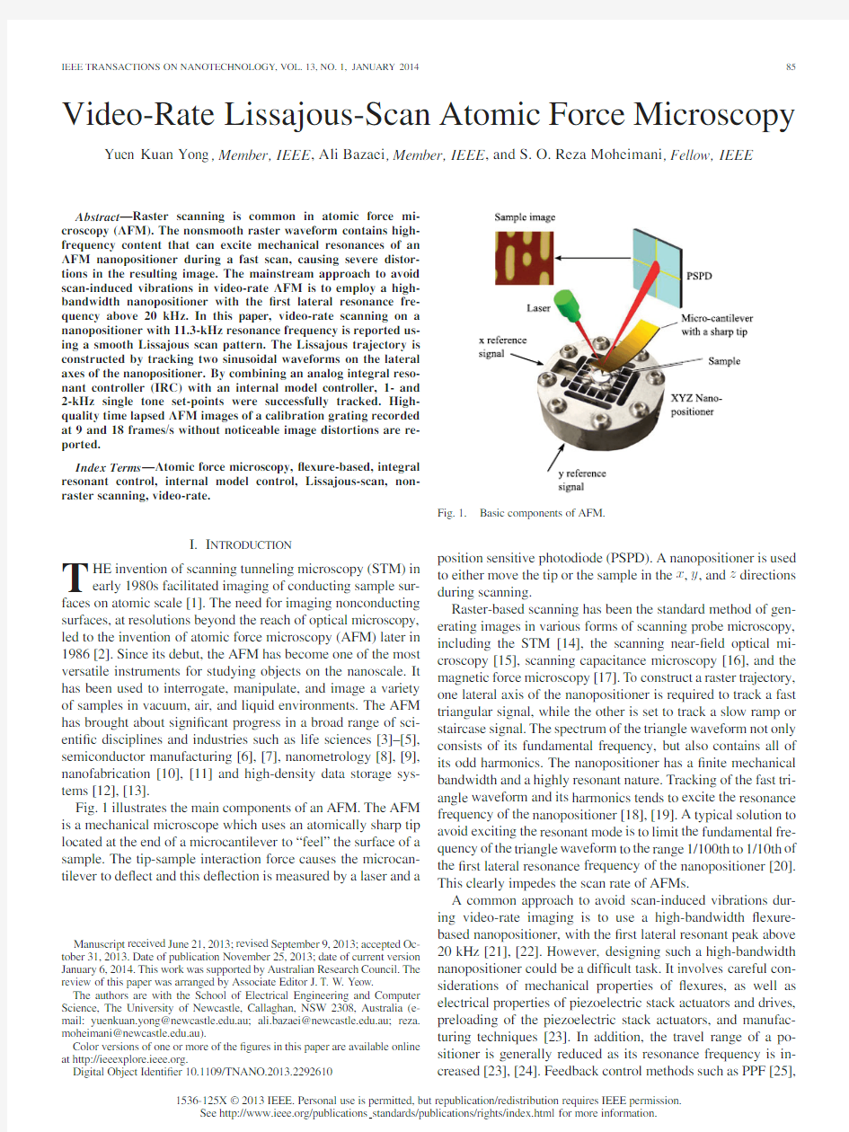
Fig.1illustrates the main components of an AFM.The AFM is a mechanical microscope which uses an atomically sharp tip located at the end of a microcantilever to“feel”the surface of a sample.The tip-sample interaction force causes the microcan-tilever to de?ect and this de?ection is measured by a laser and a
Manuscript received June21,2013;revised September9,2013;accepted Oc-tober31,2013.Date of publication November25,2013;date of current version January6,2014.This work was supported by Australian Research Council.The review of this paper was arranged by Associate Editor J.T.W.Yeow.
The authors are with the School of Electrical Engineering and Computer Science,The University of Newcastle,Callaghan,NSW2308,Australia(e-mail:yuenkuan.yong@https://www.doczj.com/doc/1f7558261.html,.au;ali.bazaei@https://www.doczj.com/doc/1f7558261.html,.au;reza. moheimani@https://www.doczj.com/doc/1f7558261.html,.au).
Color versions of one or more of the?gures in this paper are available online at https://www.doczj.com/doc/1f7558261.html,.
Digital Object Identi?er
10.1109/TNANO.2013.2292610Fig.1.Basic components of AFM.
position sensitive photodiode(PSPD).A nanopositioner is used to either move the tip or the sample in the x,y,and z directions during scanning.
Raster-based scanning has been the standard method of gen-erating images in various forms of scanning probe microscopy, including the STM[14],the scanning near-?eld optical mi-croscopy[15],scanning capacitance microscopy[16],and the magnetic force microscopy[17].To construct a raster trajectory, one lateral axis of the nanopositioner is required to track a fast triangular signal,while the other is set to track a slow ramp or staircase signal.The spectrum of the triangle waveform not only consists of its fundamental frequency,but also contains all of its odd harmonics.The nanopositioner has a?nite mechanical bandwidth and a highly resonant nature.Tracking of the fast tri-angle waveform and its harmonics tends to excite the resonance frequency of the nanopositioner[18],[19].A typical solution to avoid exciting the resonant mode is to limit the fundamental fre-quency of the triangle waveform to the range1/100th to1/10th of the?rst lateral resonance frequency of the nanopositioner[20]. This clearly impedes the scan rate of AFMs.
A common approach to avoid scan-induced vibrations dur-ing video-rate imaging is to use a high-bandwidth?exure-based nanopositioner,with the?rst lateral resonant peak above 20kHz[21],[22].However,designing such a high-bandwidth nanopositioner could be a dif?cult task.It involves careful con-siderations of mechanical properties of?exures,as well as electrical properties of piezoelectric stack actuators and drives, preloading of the piezoelectric stack actuators,and manufac-turing techniques[23].In addition,the travel range of a po-sitioner is generally reduced as its resonance frequency is in-creased[23],[24].Feedback control methods such as PPF[25],
1536-125X?2013IEEE.Personal use is permitted,but republication/redistribution requires IEEE permission.
See https://www.doczj.com/doc/1f7558261.html,/publications standards/publications/rights/index.html for more information.
resonant control[26],integral resonant control(IRC)[27]–[30], and shunt damping[31],[32]have also been used to suppress resonance frequencies of nanopositioners,and hence,to mini-mize structural vibrations induced by the raster signal.Another approach to avoid the excitation of structural resonant modes is input-shaping[33],[34].Feedforward control techniques[19], [24],[35]have also been implemented to improve the tracking performance of nanopositioners during high-speed rastering. Recently,nonraster scan methods such as spiral-scan[36], cycloid-scan[37],and Lissajous-scan methods[38],[39]have been proposed to signi?cantly increase the scan speed of AFMs. All these nonraster scan methods involve tracking sinusoidal references on the lateral axes of the nanopositioner.Unlike the triangular signals,sinusoids have narrow frequency spectrums. For a nanopositioner with a limited bandwidth,tracking of sinu-soidal references is a much easier task than tracking of triangular signals.An example can be found in[38]where vibration-free AFM images were obtained by tracking a600-Hz Lissajous tra-jectory in closed-loop using a piezoelectric tube scanner with 825-Hz resonance frequency.These scan results would be dif?-cult to achieve using the conventional raster-scan method. This paper extends our previous work on high-speed AFM based on tracking Lissajous patterns,reported in[38],to video-rate AFM using a high-speed nanopositioner with lateral resonance frequency of11.3kHz.An analog integral resonant controller(IRC)is designed and implemented to suppress the ?rst dominant mode of each lateral axis of the nanopositioner. Internal model(IM)controllers are designed for the damped system and implemented to track1-and2-kHz sinusoidal references.The inclusion of high harmonic components in the IM controllers signi?cantly improves the tracking errors. Compared to the previous video-rate AFM methods reported in[40]–[42]that are based on conventional raster scanning, in open loop,and on higher bandwidth nanopositioners, the proposed video-rate Lissajous scan method uses noise resilient IM controllers and a lower bandwidth nanopositioner. Compared to the low-speed Lissajous scan method presented in[39],which uses linear H∞controllers,the high-speed method proposed here uses IM control that can compensate for the residual tracking errors due to piezoelectric actuator nonlinear effects such as hysteresis and creep.
The remainder of the paper continues as follows.A brief description of the Lissajous pattern is presented in Section II. Section III outlines the procedures involved in constructing a video-rate Lissajous pattern for the AFM.Section IV discusses the experimental setup.Design and implementation of the ana-log IRC and the IM controllers are discussed in Section V. This section also presents the noise analysis of the open-and closed-loop systems.The open-and closed-loop AFM scans are presented in Section VI.Section VII concludes the paper.
II.L ISSAJOUS P ATTERN
The Lissajous trajectory can be generated by driving the x-and y-axes of the nanopositioner with purely sinusoidal signals that contain slightly different frequencies,that is,
x(t)=A x sin(2πf x t
)
(a)(b)
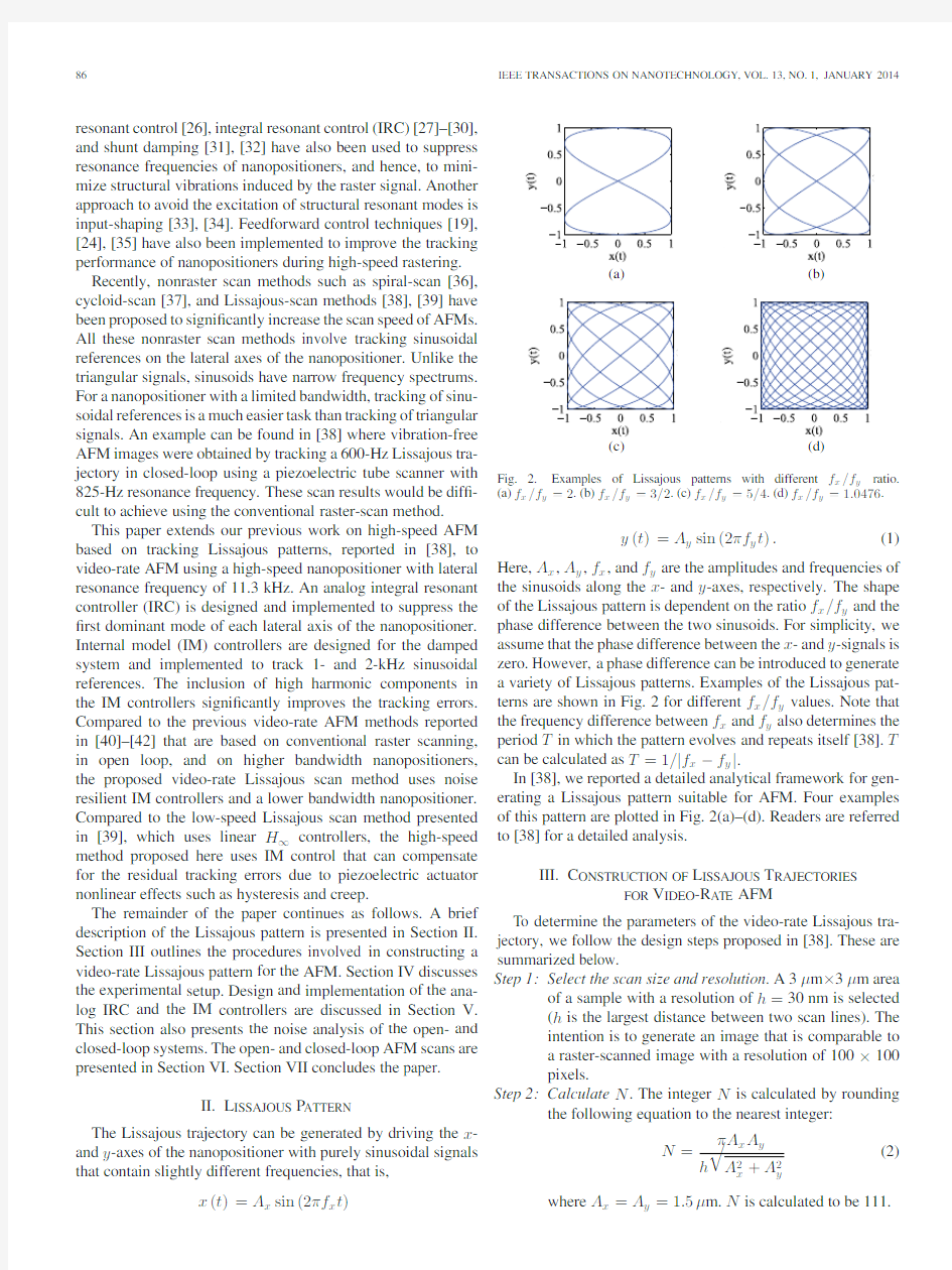
Fig. 2.Examples of Lissajous patterns with different f x/f y ratio.
(a)f x/f y=2.(b)f x/f y=3/2.(c)f x/f y=5/4.(d)f x/f y=1.0476.
y(t)=A y sin(2πf y t).(1) Here,A x,A y,f x,and f y are the amplitudes and frequencies of the sinusoids along the x-and y-axes,respectively.The shape of the Lissajous pattern is dependent on the ratio f x/f y and the phase difference between the two sinusoids.For simplicity,we assume that the phase difference between the x-and y-signals is zero.However,a phase difference can be introduced to generate a variety of Lissajous patterns.Examples of the Lissajous pat-terns are shown in Fig.2for different f x/f y values.Note that the frequency difference between f x and f y also determines the period T in which the pattern evolves and repeats itself[38].T can be calculated as T=1/|f x?f y|.
In[38],we reported a detailed analytical framework for gen-erating a Lissajous pattern suitable for AFM.Four examples of this pattern are plotted in Fig.2(a)–(d).Readers are referred to[38]for a detailed analysis.
III.C ONSTRUCTION OF L ISSAJOUS T RAJECTORIES
FOR V IDEO-R ATE AFM
To determine the parameters of the video-rate Lissajous tra-jectory,we follow the design steps proposed in[38].These are summarized below.
Step1:Select the scan size and resolution.A3μm×3μm area of a sample with a resolution of h=30nm is selected
(h is the largest distance between two scan lines).The
intention is to generate an image that is comparable to
a raster-scanned image with a resolution of100×100
pixels.
Step2:Calculate N.The integer N is calculated by rounding the following equation to the nearest integer:
N=
πA x A y
h
A2x+A2y
(2)
where A x=A y=1.5μm.N is calculated to be111.
YONG et al.:VIDEO-RATE LISSAJOUS-SCAN ATOMIC FORCE MICROSCOPY87 TABLE I
L ISSAJOUS P ARAMETERS,F RAME R ATES,AND S AMPLING F REQUENCIES
FOR A S CAN A REA OF3μM×3μM,AND A R ESOLUTION OF h=30NM
Step3:Determine the lateral scan frequencies f x and f y.f x
represents the scan frequency of the x-axis and must?t
within the mechanical bandwidth of the nanopositioner;
f y can be calculated from
f x f y =
2N
2N?1
.(3)
Equation(3)ensures that the ratio f x/f y is a rational
number.This condition guarantees that the Lissajous
trajectory returns to its starting point and repeats itself
with the same pattern after one period.We have chosen
to perform video-rate AFM at two scan speeds of f x=1
and2kHz.From(3),the respective f y values are995.49
and1990.99Hz.
Step4:Calculate the frame rate.The frame rate can be calcu-lated by f x/N.For f x=1kHz and f x=2kHz,the
frame rates are9and18frames/s,respectively.
Step5:Calculate the sampling frequency.The sampling fre-quency is required for data acquisition purposes during
AFM imaging.The sampling frequency f s can be ob-
tained from
f s=2(2N?1)f x.(4)
Table I summarizes the parameters of the two Lissajous trajec-tories,frame rates,and the corresponding sampling frequencies.
IV.E XPERIMENTAL S ETUP
A high-speed XYZ?exure-guided nanopositioner,described in[28]and[43]and pictured in Fig.3,is used to implement the video-rate Lissajous scans in a commercial AFM.The x-and y-axes of the nanopositioner are actuated by5mm×5mm×10mm piezoelectric stack actuators.The z-axis is moved by a 3mm×3mm×4mm stack actuator.The x-and y-actuators are driven by two high-bandwidth voltage ampli?ers capable of producing a peak current of1A.The z-actuator is driven by a PiezoDrive PDL200voltage ampli?er.All voltage ampli-?ers have a gain of20.The resonance frequencies of the two lateral axes are approximately11.3kHz and the z resonance fre-quency is at65kHz.The lateral and vertical full-range displace-ments of the nanopositioner are7and3μm,respectively.Two 100-kHz bandwidth MicroSense6810capacitive sensors are used to measure the x-and y-displacements of the nanoposi-tioner.The sensitivity of the sensors is2.5μm/V.All frequency responses are recorded using a HP35670A dual-channel spec-trum analyzer.
Control system implemented for each axis consists of two loops:an inner damping loop which is realized by an analog controller,and an outer tracking loop that implements an
IM Fig.3.AFM and a high-speed XYZ
nanopositioner.
Fig.4.Block diagram of control system for one axis of scanner. controller.A dSPACE-1103rapid prototyping system is used to implement the IM controllers.
V.C ONTROL D ESIGN
Fig.4shows the schematic diagram of the control system for the y-axis of the stage.Here,the plant,G y(s)refers to the transfer function from the input voltage u y of the high-voltage ampli?er(whose output is applied to the y-axis piezoelectric actuator)to the voltage v y m,measured by the y-axis displace-ment sensor.A similar control system,not shown for brevity,is designed for the x-axis.
Open-loop frequency response of the plant is shown in Fig.5. The following second-order transfer function was?tted to the
88IEEE TRANSACTIONS ON NANOTECHNOLOGY,VOL.13,NO.1,JANUARY2014
TABLE II
P ARAMETER V ALUES OF THE C ONTROL S
YSTEMS
Fig.5.Frequency responses of the open-loop plant,the compensator,and the
damping loop.
experimentally obtained data.Fig.5illustrates that this model
?ts the measured data very closely
G y(s)=0.01743s2?5300s+9.168×10⁸
s2+8942s+6.635×10⁹
.(5)
The control system for each axis consists of two feedback loops;an inner loop and an outer loop.The inner loop consists of a?rst-order IRC,denoted by C(s),that is designed to alleviate the highly resonant dynamics of the stage.Parameter values of this compensator are reported in Table II.The associated frequency response is shown in Fig.5.
The effectiveness of the damping controller can be observed from the experimentally obtained closed-loop frequency re-sponse of the inner loop(from the input w y to the sensor output v y m in Fig.4),plotted in Fig.5.The IRC reduces the resonance peak from19to only2dB,which is a signi?cant improvement. The associated stability margins are10dB and?128?.Given the simple structure of the damping controller,the large band-width of the highly resonant plant and sampling rate limitations of our real-time control system(dSPACE-DS1103),we decided to implement the damping controller using the analog circuit shown in Fig.6.The circuit has a negative dc gain which is compensated by out of phase sensing and actuation con?gu-rations in the stage(not shown for brevity).The outer loop is digitally implemented using
dSPACE.Fig.6.Circuit diagram of the analog system used to implement the damping loop.The minus sign at the output is for consistency with Fig.4,where the negative dc gain of the circuit is cancelled by the out-of-phase sensor/actuator con?gurations of the stage,which is excluded from the plant model(5)for brevity.
Due to the limited sampling rate of80kHz in dSPACE,there exist small discontinuities in the discretized controller output w y that cannot excite any vibrations as the inner loop is a well-damped continuous system.If both loops were implemented by dSPACE,such discontinuities would directly be applied to the plant input u y,exciting the resonant mode of the stage,lead-ing to undesirable vibrations.Fig.5also shows the simulated frequency response of the damping loop using the plant model (5)and the?rst order compensator model,where a good match with the experimental closed-loop data of the inner loop con-?rms a valid implementation of the damping loop by the analog circuit.The damping performance is also con?rmed by the step responses shown in Fig.7.
Having well-damped and hence better conditioned plants as-sociated with both x-and y-axes,we can incorporate IM con-trollers in the outer loops to achieve accurate tracking of the sinusoidal set-points as required in Lissajous scan AFM.As shown in Fig.4,the IM controller C2(s)contains an integrator and a second-order transfer function with imaginary poles that match the fundamental frequency of the sinusoidal reference (?rst harmonic IM).We have also included second-order trans-fer functions that correspond to the second and third harmonics of the reference in the controller.These additional controllers can improve the steady-state tracking error resulting from plant nonlinearities such as hysteresis and creep,that manifest as harmonics of the reference frequency[38].Note that due to the nonlinearities,a pure single-tone sinusoidal actuation is not enough to generate the desired sine wave output.Assuming a static nonlinearity,the ideal actuation waveform generating the desired one-tone output(reference)through a nonlinear sys-tem is generally a periodic signal with the same period,which has in?nite number of harmonics in addition to its fundamental component.If only one sinusoidal oscillator,at the fundamen-tal frequency,is implemented in the IM controller,it cannot
YONG et al.:VIDEO-RATE LISSAJOUS-SCAN ATOMIC FORCE MICROSCOPY
89
Fig.7.Normalized step responses of the plant and the damping loop ob-tained by simulation and experiment.(a)Experimental step responses.(b)Step responses by simulation.generate the higher harmonics required for the ideal actuation,resulting in a nonzero residual output error.
For the two reference frequencies of 1and 2kHz,the pa-rameter values of the IM controllers are recorded in Table II and the associated stability margins are (6.8dB,52?)and (10.8dB,57?),respectively.Fig.8shows the experimentally obtained and the simulated unit-step-responses of the control systems,demonstrating the modeling accuracy and acceptable transient performances in a worst-case scenario.
We are now in a position to experimentally assess the perfor-mance of the control system in tracking 1-and 2-kHz sinusoidal references,required for video-rate Lissajous scans.We also in-vestigate the effectiveness of controlling higher order harmonics in the IM controller.Both x -and y -axes of the scanner are si-multaneously driven,via their control systems,by sinusoidal references that slightly differ in frequency (by approximately 0.45%).Each reference signal has an amplitude of 1.5μm and a zero bias.
Fig.9shows the resulting steady-state tracking errors,with and without the third harmonic IM,for the 1-kHz control system.The root-mean-square (RMS)value of the positioning errors is also indicated.It can be observed that incorporating the third harmonic IM in the controller signi?cantly improves the track-ing performance.The experimentally obtained results for the 2-kHz control system,shown in Fig.10,also demonstrate simi-lar improvements,con?rming the advantages of the high-order harmonic elements in the IM controller.A nanometer-scale po-sitioning accuracy is achieved while tracking a 2-kHz sinusoidal reference that swings in the micrometer range,by proper con-trol of a nanopositioner whose resonance is at 11.3kHz and
is
(a)
(b)
Fig.8.Unit step responses of the control systems obtained by simulation and experiment.(a)Unit-step-response of closed-loop system with 1-kHz IM con-troller.(b)Unit-step-response of closed-loop system with 2-kHz IM
controller.
Fig.9.Experimental steady-state tracking errors of the 1-kHz control sys-tem for sinusoidal references with peak-to-peak amplitude of 3μm ,with and without the third harmonic IM component in controller C 2(s ).(a)Steady-state tracking errors for 1-kHz control system for y -axis.(b)Steady-state tracking errors for 1-kHz control system for x -axis.
subjected to uncertainties and nonlinearities such as hysteresis,creep,and cross coupling.
90IEEE TRANSACTIONS ON NANOTECHNOLOGY,VOL.13,NO.1,JANUARY
2014 Fig.10.Experimental steady-state tracking errors of the2-kHz control sys-
tem for sinusoidal references with peak-to-peak amplitude of3μm,with and
without the third and the second harmonic IM components in controller C2(s).
(a)Steady-state tracking errors for2-kHz control system of y-axis.(b)Steady-
state tracking errors for2-kHz control system of x-axis.
We are now in a position that we may assess the noise re-
jection properties of the1-and2-kHz control systems.We?rst
measured the sensor noise output of the open-loop system(when
the system was not actuated).Using the block diagram of the
control system in Fig.4,the transfer function from the noise
source to the actual plant output y a:=2.5v y(projected noise)
is
T n(s):=y a(s)
n(s)
=?2.5
L n(s)
1+L n(s)
(6)
where L n=(2.5C2?1)CG,and factor of2.5μm/V converts the sensor output voltage to displacement.Applying no refer-ences,the actual plant output was calculated as the projected noise using the aforementioned plant model.Fig.11shows the results in time and frequency https://www.doczj.com/doc/1f7558261.html,pared to7.5nm rms value of the noise source,the rms values of the projected noise in1-and2-kHz control systems are1.2and1.3nm,respec-tively.Hence,the proposed controllers also reduce the effect of sensor noise on the controlled position while maintaining highly acceptable tracking performances.
VI.AFM R ESULTS
This section evaluates the AFM imaging performance of the nanopositioner with the implementation of the proposed control strategies discussed in Section V.The feedback con-trolled nanopositioner is mounted under a commercial Nanosurf EasyScan2AFM,as shown in Fig.3.Thus,the scanning stage of this commercial AFM is replaced with the high-speed nanopo-sitioner.An ASM750-HD calibration grating is used to
evaluate Fig.11.Measured noise source and the resulting projected noises in the control systems in time and frequency
domains.
Fig.12.Open-loop images obtained at18frames/s(f x=2kHz).The image was severely distorted due to vibrations and poor tracking performance.
the video-rate images.The grating has a step height of100nm and a pitch of738nm.A National Instruments4MS/s PXI-6124 data acquisition card is used to record the images.
AFMs can be operated in contact,semicontact,and dynamic modes.Details of these scanning modes can be found in[44], [19]and[23].AFM images presented here were obtained in constant-height contact-mode.In this mode,the vertical feed-back loop is deactivated during scanning.The3-D topographic images of the sample were constructed by plotting the de?ec-tion of the microcantilever versus the x-and y-positions of the sample.
Fig.12shows the open-loop image of a3μm×3μm sam-ple area obtained at18frames/s(f x=2kHz).The image was
YONG et al.:VIDEO-RATE LISSAJOUS-SCAN ATOMIC FORCE MICROSCOPY
91
Fig.13.Sequence of Lissajous images showing the process of fast zooming in of a sample area from3μm×3μm to1μm×1μm.Every third image in the series is illustrated above.These series of images were captured at(a)9frames/s(f x=1kHz)and(b)18frames/s(f x=2kHz).
severely distorted due to vibrations and poor tracking perfor-mance of the nanopositioner in open loop.
Fig.13illustrates a sequence of closed-loop Lissajous images which were obtained at9frames/s(f x=1kHz)and18frames/s (f x=2kHz).The images show a rapid zooming-in process on a sample area from3μm×3μm to1μm×1μm.Every third image in the sequence is shown in the?gure.With the proposed control strategies implemented,the image artifacts due to vibrations and poor tracking were eliminated.
VII.C ONCLUSION
In this paper,a nonraster scan method based on following a Lissajous pattern was used to achieve video-rate atomic force microscopy on a11.3-kHz nanopositioner.An analog integral resonant controller was designed and implemented to suppress the?rst resonant mode of each lateral axis of the nanoposi-tioner by17dB.IM controllers incorporating higher harmonic components were used to signi?cantly improve the tracking er-rors of the scanner.It was shown that the projected noise is much smaller than the sensor noise.This implies that the proposed control strategies are capable of reducing the effect of sensor noise at the controlled position and simultaneously achieving high tracking performances.By combining the Lissajous-scan method with the proposed IRC and IM controllers,high-quality AFM images were successfully recorded at9and18frames/s.
R EFERENCES
[1]G.Binnig,H.Rohrer,C.Gerber,and E.Weibel,“Surface studies by
scanning tunneling microscopy,”vol.49,no.1,pp.57–61,1982.
[2]G.Binnig,C.F.Quate,and C.Gerber,“Atomic force microscope,”vol.
56,pp.930–933,1986.
[3]T.Ando,“High-speed atomic force microscopy coming of age,”Nan-
otechnology,vol.23,no.6,p.062001,2012.
[4]T.Ando,T.Uchihashi,N.Kodera,D.Yamamoto,A.Miyagi,M.Taniguchi,
and H.Yamashita,“High-speed AFM and nano-visualization of biomolecular processes,”P?¨u gers Archiv.Eur.J.Physiol.,vol.456,no.1, pp.211–225,2008.
92IEEE TRANSACTIONS ON NANOTECHNOLOGY,VOL.13,NO.1,JANUARY2014
[5]P.Hinterdorfer and Y.F.Dufrene,“Detection and localization of single
molecular recognition events using atomic force microscopy,”Nature Methods,vol.3,pp.347–355,2006.
[6]K.Wiesauer and G.Springholz,“Fabrication of semiconductor nanos-
tructures by nanoindentation of photoresist layers using atomic force mi-croscopy,”J.Appl.Phys.,vol.88,no.12,pp.7289–7297,2000.
[7]R.A.Oliver,“Advances in AFM for the electrical characterization of
semiconductors,”Rep.Progr.Phys.,vol.71,no.7,p.076501,2008. [8]Y.Hua,C.Coggins,and S.Park,“Advanced3D metrology atomic force
microscope,”in Proc.IEEE/SEMI Adv.Semicond.Manuf.Conf.,2010, pp.7–10.
[9]L.Tetard, A.Passian,R.H.Farahi, B.H.Davison,S.Jung,
A.J.Ragauskas,A.L.Lereu,and T.Thundat,“Nanometrology of delig-
ni?ed Populus using mode synthesizing atomic force microscopy,”Nan-otechnology,vol.22,no.46,p.465702,2011.
[10]J.A.Vicary and https://www.doczj.com/doc/1f7558261.html,es,“Real-time nanofabrication with high-speed
atomic force microscopy,”Nanotechnology,vol.20,no.9,p.095302, 2009.
[11]S.Kim and S.-W.Kim,“AFM-based nanofabrication with assistance of
femtosecond pulse laser radiation,”J.Phys.:Conf.Series,vol.61,no.1, pp.550–554,2007.
[12]G.Binnig,M.Despont,U.Drechsler,W.Haberle,M.Lutwyche,
P.Vettiger,H.Mamin,B.Chui,and T.Kenny,“Ultrahigh-density atomic force microscopy data storage with erase capability,”Appl.Phys.Lett., vol.74,no.9,pp.1329–1331,1999.
[13]P.Vettiger,G.Cross,M.Despont,U.Drechsler,U.D¨u rig,B.Gotsmann,
W.H¨a berle,https://www.doczj.com/doc/1f7558261.html,ntz,H.E.Rothuizen,R.Stutz,and G.K.Binnig,“The‘Milipede’—Nanotechnology entering data storage,”vol.1,no.1, pp.39–55,2002.
[14]G.Binnig and H.Rohrer,“The scanning tunneling microscope,”Scientif.
Amer.,vol.253,pp.50–56,1986.
[15] D.W.Pohl,U.C.Fischer,and U.T.Drig,“Scanning near-?eld opti-
cal microscopy(SNOM),”J.Microsc.,vol.152,no.3,pp.853–861, 1988.
[16] C.C.Williams,W.P.Hough,and S.A.Rishton,“Scanning capacitance
microscopy on a25nm scale,”Appl.Phys.Lett.,vol.55,no.2,pp.203–205,1989.
[17]Y.Martin and H.K.Wickramasinghe,“Magnetic imaging by‘force mi-
croscopy’with1000[A-ring]resolution,”Appl.Phys.Lett.,vol.50,no.20, pp.1455–1457,1987.
[18]S.O.R.Moheimani,“Invited review article:Accurate and fast nanopo-
sitioning with piezoelectric tube scanners:Emerging trends and future challenges,”Rev.Scientif.Instrum.,vol.79,no.7,p.071101,2008. [19]G.M.Clayton,S.Tien,K.K.Leang,Q.Zou,and S.Devasia,“A review of
feedforward control approaches in nanopositioning for high-speed SPM,”
J.Dyn.Syst.,Meas.,Control,vol.131,no.6,p.061101,2009.
[20]S.Devasia,E.Eleftheriou,and S.O.R.Moheimani,“A survey of control
issues in nanopositioning,”vol.15,pp.802–823,2007.
[21]G.Schitter,K.J.?Astrom,B.DeMartini,P.J.Thurner,K.L.Turner,and
P.K.Hansma,“Design and modeling of a high-speed AFM-scanner,”vol.
15,no.5,pp.906–915,2007.
[22] B.J.Kenton and K.K.Leang,“Design and control of a three-axis serial-
kinematic high-bandwidth nanopositioner,”IEEE/ASME Trans.Mecha-tronics,vol.17,no.2,pp.356–368,2012.
[23]Y.K.Yong,S.O.R.Moheimani,B.J.Kenton,and K.K.Leang,“In-
vited review article:High-speed?exure-guided nanopositioning:Mechan-ical design and control issues,”Rev.Scientif.Instrum.,vol.83,no.12, p.121101,2012.
[24]Y.K.Yong,S.Aphale,and S.O.R.Moheimani,“Design,identi?cation
and control of a?exure-based XY stage for fast nanoscale positioning,”
IEEE Trans.Nanotechnol.,vol.8,no.1,pp.46–54,Jan.2009.
[25] B.Bhikkaji,M.Ratnam,A.J.Fleming,and S.O.R.Moheimani,“High-
performance control of piezoelectric tube scanners,”vol.15,no.5,pp.
853–866,2007.
[26] A.Sebastian, A.Pantazi,S.O.R.Moheimani,H.Pozidis,and
E.Eleftheriou,“Achieving sub-nanometer precision in a MEMS storage
device during self-servo write process,”IEEE Trans.Nanotechnol.,vol.7, no.5,pp.586–595,Sep.2008.
[27]S.S.Aphale,A.J.Fleming,and S.O.R.Moheimani,“Integral resonant
control of collocated smart structures,”Smart Mater.Struct.,vol.16, pp.439–446,2007.
[28]Y.K.Yong,B.Bhikkaji,and S.O.R.Moheimani,“Design,modeling and
FPAA-based control of a high-speed atomic force microscope nanoposi-tioner,”IEEE/ASME Trans.Mechatronics,vol.18,no.3,pp.1060–1071, Jun.2013.[29] A.J.Fleming,S.Aphale,and S.O.R.Moheimani,“A new method for
robust damping and tracking control of scanning probe microscope posi-tioning stages,”IEEE Trans.Nanotechnol.,vol.9,no.4,pp.438–448,Jul.
2010.
[30]Y.K.Yong,A.Fleming,and S.O.R.Moheimani,“A novel piezoelectric
strain sensor for simultaneous damping and tracking control of a high-speed nanopositioner,”IEEE/ASME Trans.Mechatronics,vol.18,no.3, pp.1113–1121,Jun.2013.
[31]S.Aphale,A.J.Fleming,and S.O.R.Moheimani,“High speed nano-
scale positioning using a piezoelectric tube actuator with active shunt control,”Micro Nano Lett.,vol.2,no.1,pp.9–12,2007.
[32] A.A.Eielsen and A.J.Fleming,“Passive shunt damping of a piezoelectric
stack nanopositioner,”in Proc.Amer.Control Conf.,2010,pp.4963–4968.
[33]G.Schitter,P.J.Thurner,and P.K.Hansma,“Design and input-shaping
control of a novel scanner for high-speed atomic force microscopy,”
Mechatronics,vol.18,pp.282–288,2008.
[34] A.J.Fleming and A.G.Wills,“Optimal periodic trajectories for band-
limited systems,”IEEE Trans.Control.Syst.Technol.,vol.13,no.3, pp.552–562,May2009.
[35]K.K.Leang and S.Devasia,“Feedback-linearized inverse feedforward for
creep,hysteresis,and vibration compensation in piezoactuators,”IEEE Control Syst.Technol.:Spec.Issue Dyn.Control Micro-Nano-Scale Syst., vol.15,no.5,pp.927–935,Sep.2007.
[36]I.A.Mahmood,S.O.R.Moheimani,and B.Bhikkaji,“A new scanning
method for fast atomic force microscopy,”IEEE Trans.Nanotechnol., vol.10,no.2,pp.203–216,Mar.2011.
[37]Y.K.Yong,S.O.R.Moheimani,and I.R.Petersen,“High-speed cycloid-
scan atomic force microscopy,”Nanotechnology,vol.21,no.36, p.365503,2010.
[38] A.Bazaei,Y.K.Yong,and S.O.R.Moheimani,“High-speed Lissajous-
scan atomic force microscopy:Scan pattern planning and control design issues,”Rev.Scientif.Instrum.,vol.83,no.6,p.063701,2012.
[39]T.Tuma,J.Lygeros,V.Kartik,A.Sebastian,and A.Pantazi,“High-
speed multiresolution scanning probe microscopy based on Lissajous scan trajectories,”Nanotechnology,vol.23,no.18,p.185501,2012.
[40] A.D.L.Humphris,J.K.Hobbs,and https://www.doczj.com/doc/1f7558261.html,es,“Ultrahigh-speed scan-
ning near-?eld optical microscopy capable of over100frames per second,”
Appl.Phys.Lett.,vol.83,pp.6–8,2003.
[41] A.D.L.Humphris,https://www.doczj.com/doc/1f7558261.html,es,and J.K.Hobbs,“A mechanical micro-
scope:High-speed atomic force microscopy,”Appl.Phys.Lett.,vol.86, p.034106,2005.
[42]T.Ando,T.Uchihashi,and T.Fukuma,“High-speed atomic force mi-
croscopy for nano-visualization of dynamic biomolecular processes,”
Progr.Surf.Sci.,vol.83,pp.337–437,2008.
[43]Y.K.Yong and S.O.R.Moheimani,“Design of an inertially coun-
terbalanced Z-nanopositioner for high-speed atomic force microscopy,”
IEEE/ASME Trans.Nanotechnol.,vol.12,no.2,pp.137–145,Mar.2013.
[44] D.Abramovitch,S.Andersson,L.Pao,and G.Schitter,“A tutorial on
the mechanisms,dynamics,and control of atomic force microscopes,”in Proc.Amer.Control Conf.,Jul.2007,pp.
3488–3502.
Yuen Kuan Yong(M’09)received the B.Eng.de-
gree(?rst Class Hons.)in mechatronic engineering
and the Ph.D.degree in mechanical engineering from
The University of Adelaide,Adelaide,Australia,in
2001and2007,respectively.
She is currently an Australian Research Council
DECRA Fellow with the School of Electrical En-
gineering and Computer Science,The University of
Newcastle.Her research interests include the design
and control of nanopositioning systems,high-speed
atomic force microscopy,?nite-element analysis of smart materials and structures,and sensing and actuation.
Dr.Yong was a recipient of the2008IEEE/ASME International Conference on Advanced Intelligent Mechatronics(AIM)Best Conference Paper Finalist Award.She is a member of the Technical Program Committee of AIM and the International Conference on Manipulation,Manufacturing,and Measurement on the Nanoscale(3M-NANO).She is also an Associate Editor of the Editorial Board of the International Journal of Advanced Robotic Systems.
YONG et al.:VIDEO-RATE LISSAJOUS-SCAN ATOMIC FORCE MICROSCOPY
93
Ali Bazaei(M’01)received the B.Sc.and M.Sc.de-
grees from Shiraz University,Shiraz,Iran,and the
Ph.D.degrees from University of Western Ontario,
London,ON,Canada,and Tarbiat Modares Univer-
sity,Tehran,Iran,in1992,1995,2004,and2009,
respectively,all in electrical engineering.
From September1995to January2000,he was
an Instructor with Yazd University,Yazd,Iran.From
September2004to December2005,he was a Re-
search Assistant with the Department of Electrical
and Computer Engineering,University of Western Ontario,London,ON,Canada.He is currently a research academic with the School of Electrical Engineering and Computer Science,The University of Newcastle,Australia.His research interests include the general area of non-linear systems including control and modeling of structurally?exible systems, friction modeling and compensation,neural networks,and microposition sen-
sors.
S.O.Reza Moheimani(M’07–F’01)received the
B.Sc.degree in electrical and electronic engineering
from Shiraz University,Shiraz,Iran,in1990and the
M.Eng.Sc.and Ph.D.degrees in electrical and elec-
tronic engineering from the University of New South
Wales,Sydney,New South Wales,Australia,at the
Australian Defence Force Academy,Canberra,Aus-
tralia,in1993and1996,respectively.
He joined The University of Newcastle,Callaghan,
Australia,in1997,where he is a Professor of electri-
cal engineering and an Australian Research Council (ARC)Future Fellow.He is the Founder and the Director of the Laboratory for Dynamics and Control of Nanosystems,a multimillion-dollar state-of-the-art research facility.During2003–2010,he was the Associate Director of the ARC Centre of Excellence for Complex Dynamic Systems and Control.His current research interests include area of ultrahigh-precision mechatronic systems,with particular emphasis on dynamics and control at the nanometer scale,including applications of control and estimation in nanopositioning systems for high-speed scanning probe microscopy,modeling and control of microcantilever-based de-vices,control of microactuators in microelectromechanical systems,and control issues related to ultrahigh-density probe-based data-storage systems.
Prof.Moheimani is a Fellow of the International Federation of Automatic Control(IFAC)and the Institute of Physics(U.K.).He is a corecipient of the 2007IEEE TRANSACTIONS ON CONTROL SYSTEMS TECHNOLOGY Outstanding Paper Award and the2009IEEE Control Systems Technology Award,together with a group of researchers from IBM Zurich Research Labs, where he has held several visiting appointments.He has served on the editorial boards of a number of journals,including the IEEE/ASME TRANSACTIONS ON MECHATRONICS,IEEE TRANSACTIONS ON CONTROL SYSTEMS TECHNOLOGY,and Control Engineering Practice.He has chaired several in-ternational conferences and workshops and currently chairs the IFAC Technical Committee on Mechatronic Systems.
高考语文语言表达图文转换之漫画类 ——高考语言表达图文转换之漫画类 漫画以生活为土壤,以画面为契机,在方寸之间展现生活百态。它是浓缩化的生活。其特点是夸张、象征、幽默、讽刺、典型、以小见大。 漫画一般由三部分组成:标题、画面、画中字。其中标题明示或暗示主题,有无并存;画面是漫画主体,也是寓意所在;画中字提示或补充画面,有无并存。 漫画类高考考点:1.描述漫画内容;2.揭示漫画寓意;3.拟定漫画题目。现仅就前两个考点作一梳理点拨。 解题思路上:观察(整体、局部)→分析(原因)→联想(现实)。 答题方法上:描述—整体及局部特征。寓意—抓住画面特征,联系社会现实。 例一:请描述下面漫画的内容并揭示寓意。 步骤一:观察。整体:老鼠,两个人。 局部:老鼠背着“造假商”袋子,大汗淋漓,脑中想“一场虚惊……”。两 个人戴着红袖章,口大张,手中举着写有“假”“打”二字的牌子。 步骤二:分析。原因:原因:只有口号,没有行动。 步骤三:联想。现实:现实:政令执行者搞形式主义。 组织答案如下: (1)描述:图中有一只老鼠和两个人。左边一只老鼠大汗淋漓,背着写有“造假商”字样的包袱跑在路上,旁边两个戴红袖标的人张口大喊,分别手举写有“假”、“打”二字的牌子,老鼠在想:“一场虚惊,原来不是打假啊……”(描述—整体及局部特征) (2)寓意:漫画运用语言的倒置机趣,本为“打假”却成了“假打”,讽刺了叶公好龙的政令实施者。(寓意—抓住画面特征,联系社会现实) 语言表达是高考题的创新基地,以考点为基础,以生活为土壤,大搞创新,派生出种类繁多的新题型。如漫画题中的拟写标题、公益广告词、评析漫画等。万变不离其宗,以不变应万变,掌握要领,便可迎刃而解。 二、高中图文转换专题训练 2.下图是从婴儿期到青年期人际交往发展变化趋势坐标图,请根据要求完成题目。
2018年高考语文真题分类汇编 语言连贯、图文转换 一、语言表达(共4题;共17分) 1.(2018·江苏)在下面一段文字横线处填入语句,衔接最恰当的一项是()“理性经济人”,把利己看作人的天性,只追求个人利益的最大化,这是西方经济学的基本假设之一。_________,_________。_________,_________,_________,_________,更倾向于暂时获得产品或服务,或与他人分享产品或服务。使用但不占有,是分享经济最简洁的表述。 ①反而更多地采取一种合作分享的思维方式 ②不再注重购买、拥有产品或服务 ③但在分享经济这一催化剂的作用下 ④人们不再把所有权看作获得产品的最佳方式 ⑤在新兴的互联网平台上 ⑥这个利己主义的假设发生了变化 A.③⑥⑤①④② B.③⑥⑤④②① C.⑤⑥③①④② D.⑤⑥③④②① 2.(2018?浙江)在下面一段文字横线处补写恰当的语句,使整段文字语意完整连贯,内容贴切,逻辑严密。每处不超过15个字。植物的生长与光合作用、呼吸作用及蒸腾作用有关,________,所以温度直接影响植物的生长。温度的变化,既影响植物吸收肥料的程度,也影响植物的新陈代谢过程,________,都会使植物新陈代谢的酶活性发生变化,只有适宜的温度才能使新陈代谢达到最佳状态,利于植物的快速成长。据研究,________,即根、冠、叶的温度都有差异,而根温对植物的生长影响最直接。 3.(2018?卷Ⅲ)阅读下面的文字,完成小题。 除了人会为了理想奔波迁徒以外,很多动物也有着自己________的迁徒盛举,冬季来临,天气寒冷,食物短缺,很多动物选择集体逃离,待到春暖花开、万物复苏再一起回来。动物迁徙是有确定路线的。它们对驻地有着自己的坚守和执着,而不是________。对于动物究竟如何确定自己的迁徙路线,科学家一直都充满好奇。有科学家认为,迁徙动物都有独特的“助航设施”,它们通过海岸线等作为参照,利用特殊的嗅觉和听觉等获得方向,也有科学家认为,迁徒动物身体中存在磁受体,可以感应地球磁场,它们有自己的生物指南针,更有趣的是,又有科学家发现即使是室内饲养的,从未接触过其他同伴的年轻乌鸦,也会沿着祖辈飞过的路线进行迁徙,也就是说,(_____________),它们天生就知道去哪里寻找温暖的地方过冬。到目前为止,关于动物迁徒路线确定的问题,科学家仍在________地进行探究,我们期待着更加________的故事出现。 (1)依次填入文中横线上的成语,全都恰当的一项是 () A. 波澜壮阔;随波逐流;宵衣旰食;引人入胜 B. 波澜壮阔;随遇而安;全力以赴;引人入胜
语言文字运用之图文转换 考点清单: 在媒体信息交流和传递中,图表是几种重要的表现形式之一,它能直观鲜明、简洁明了地反映事物的发展变化规律或作者的观点态度。常见的图表形式有公司单位的报表、企业厂家生产增长图、工艺生产流程图、实验研究变化曲线图等。简洁的图表包含着大量的文字和数字信息,涉及不同的知识领域。 图文转换综合考查对材料的分析能力,要求从原始材料中筛选信息,进行分析、综合,并运用简明的语言概括出观点。 考纲解读: 图文转换题还是考查语言运用中的压缩、概括 和表达,是对学生观察能力、理解能力、语言表达 能力的考查。 考查容: 图文转换题要求考生根据图表中的有关容,分 析有关材料,辨别或挖掘某些隐含性信息,或对材 料进行综合性评价,题目类型主要分三类: 一、表文类 解读及技巧: 图表解读流程:图表---观察认读---分析理解---归纳概括---文字表达。 1.认真审题,明确要求 注意表头和表注的文字,弄清楚图表说明的对象和比较的角度,以及题目中对句式的要求和字数的限制。 2.仔细认读图表,全面准确捕捉信息 A认真观察图表,找出图表中所含的信息:比较对象、比较项目、各种数据及变化特点等。具体而言,图表式的要兼顾图表的各个要素,坐标曲线图要抓住曲线变化的规律,柱状、饼状图要抓住各要素的比例分配及变化情况,生产流程图要抓住事理的时空、逻辑顺序等。 B 重视数据变化。 C 注重图表细节,如图表下的“注”等。 3.表达用词 表明增长趋势:“增长(加)了”“增加到”“增长了xx倍”“与同期相比,增长……”等。 表明下降趋势:“减少了\到(百分数\分数)”,注意其后不能用倍数。 表示程度围的概念:“近一半(约50%)”“大部分(比例约在55%~70%)”“绝大多数(比例占70%以上)”“所有”“约几成”等。 根据图表数据变化规律来选用词语表达。 4.检查答案
语言文字运用之图文转换考点清单:简洁明了在媒体信息交流和传递中,图表是几种重要的表现形式之一,它能直观鲜明、企业厂常见的图表形式有公司单位的报表、地反映事物的发展变化规律或作者的观点态度。简洁的图表包含着大量的文字和实验研究变化曲线图等。家生产增长图、工艺生产流程图、数字信息,涉及不同的知识领域。图文转换综合考查对材料的分析能力,要求从原始材料中筛选信息,进行分析、综合,并运用简明的语言概括出观点。 考纲解读:图文转换题还是考查语言运用中的压缩、概括和表达,是对学生观察能力、理解能力、语言表达能力的考查。 考查内容: 图文转换题要求考生根据图表中的有关内容,分析有关材料,辨别或挖掘某些隐含性信息,或对材料进行综合性评价,题目类型主要分三类: 一、表文类 解读及技巧: 图表解读流程:图表---观察认读---分析理解---归纳概括---文字表达。 1.认真审题,明确要求 注意表头和表注的文字,弄清楚图表说明的对象和比较的角度,以及题目中对句式的要求和字数的限制。 2.仔细认读图表,全面准确捕捉信息 A认真观察图表,找出图表中所含的信息:比较对象、比较项目、各种数据及变化特点等。具体而言,图表式的要兼顾图表的各个要素,坐标曲线图要抓住曲线变化的规律,柱状、饼状图要抓住各要素的比例分配及变化情况,生产流程图要抓住事理的时空、逻辑顺序等。 B 重视数据变化。 C 注重图表细节,如图表下的“注”等。 3.表达用词 表明增长趋势:“增长(加)了”“增加到”“增长了xx倍”“与同期相比,增长……”等。表明下降趋势:“减少了\到(百分数\分数)”,注意其后不能用倍数。 表示程度范围的概念:“近一半(约50%)”“大部分(比例约在55%~70%)”“绝大多数(比例占70%以上)”“所有”“约几成”等。 根据图表数据变化规律来选用词语表达。 4.检查答案 信息是否多余或遗漏缺失、信息推断是否错误、答案是否存在语病。
高考语文真题分类汇编语言连贯图文转换附答 案解析 HUA system office room 【HUA16H-TTMS2A-HUAS8Q8-HUAH1688】
2018年高考语文真题分类汇编: 语言连贯、图文转换附答案解析 ——2018年6月18日《》 【答案解析部分】 一、语言表达(共4题;共17分) 1.(2018·江苏)在下面一段文字横线处填入语句,衔接最恰当的一项是() “理性经济人”,把利己看作人的天性,只追求个人利益的最大化,这是西方经济学的基本假设之一。_________,_________。_________,_________, _________,_________,更倾向于暂时获得产品或服务,或与他人分享产品或服务。使用但不占有,是分享经济最简洁的表述。 ①反而更多地采取一种合作分享的思维方式 ②不再注重购买、拥有产品或服务 ③但在分享经济这一催化剂的作用下 ④人们不再把所有权看作获得产品的最佳方式 ⑤在新兴的互联网平台上 ⑥这个利己主义的假设发生了变化 A.③⑥⑤①④② B.③⑥⑤④②① C.⑤⑥③①④② D.⑤⑥③④②①
2.(2018?浙江)在下面一段文字横线处补写恰当的语句,使整段文字语意完整连贯,内容贴切,逻辑严密。每处不超过15个字。植物的生长与光合作用、呼吸作用及蒸腾作用有关,________,所以温度直接影响植物的生长。温度的变化,既影响植物吸收肥料的程度,也影响植物的新陈代谢过程,________,都会使植物新陈代谢的酶活性发生变化,只有适宜的温度才能使新陈代谢达到最佳状态,利于植物的快速成长。据研究,________,即根、冠、叶的温度都有差异,而根温对植物的生长影响最直接。 3.(2018?卷Ⅲ)阅读下面的文字,完成小题。 除了人会为了理想奔波迁徒以外,很多动物也有着自己________的迁徒盛举,冬季来临,天气寒冷,食物短缺,很多动物选择集体逃离,待到春暖花开、万物复苏再一起回来。动物迁徙是有确定路线的。它们对驻地有着自己的坚守和执着,而不是________。对于动物究竟如何确定自己的迁徙路线,科学家一直都充满好奇。有科学家认为,迁徙动物都有独特的“助航设施”,它们通过海岸线等作为参照,利用特殊的嗅觉和听觉等获得方向,也有科学家认为,迁徒动物身体中存在磁受体,可以感应地球磁场,它们有自己的生物指南针,更有趣的是,又有科学家发现即使是室内饲养的,从未接触过其他同伴的年轻乌鸦,也会沿着祖辈飞过的路线进行迁徙,也就是说,(_____________),它们天生就知道去哪里寻找温暖的地方过冬。到目前为止,关于动物迁徒路线确定的问题,科学家仍在________地进行探究,我们期待着更加________的故事出现。 (1)依次填入文中横线上的成语,全都恰当的一项是() A. 波澜壮阔;随波逐流;宵衣旰食;引人入胜
考点6 图文转换 命题特点 考查重点命题趋势 图文(表文)转换题涉及准确、生动、简明、连贯、得体、修辞等诸多考点,综合考查考生描述、提炼、概括等各方面的能力,更涉及考生观察社会、分析问题的能力和语言综合表达能 力以说明图表内容、揭示图 表漫画寓意、总结图表规 律以及描绘图画画面等 为主要命题点,2014年、 2015年均以客观选择题 的形式考查 1.一般以选择 题的形式考查 2.与其他考点 结合,综合考查 语言表达能力 1.(2015·江苏卷)下列对“中国文化遗产”标志理解不恰当 ...的一项是( ) A.标志整体呈圆形,既体现民族团结、和谐包容的文化内涵,也体现文化遗产保护的理念。 B.标志中的太阳神鸟图案动感很强,既体现中国文化强大的向心力,也体现自强不息的民族精神。 C.标志中的神鸟与太阳光芒的数目,暗合中国文化中四季、四方、十二生肖、十二时辰等元素。 D.标志中光芒四射的太阳,既象征着光明、生命和永恒,也象征着我国飞速发展的文化产业。 D[本题以图文转换的形式考查对画面的理解。实质考查对图案及寓意的理解。D项,“也象征着我国飞速发展的文化产业”不合适。] 【真题点评】该题是图文转换题。考查的形式仍继续沿用2014年的命题形式,即以客观题的形式考查对图(2015年为徽标)内涵的理解。一般图文转换题中的“图”往往比较抽象,寓意比较深刻,在仔细观察的同时,还要展开联想和想象。如2015年江苏卷的对“中
国文化遗产”标志的理解,既要仔细分析标志的组成部分,更要对标志中的组成部分——圆形、太阳、鸟的寓意进行联想和想象,同时要扣住“中国文化遗产”这一主题。 2.(2014·江苏卷)阅读下边这幅漫画,对它的寓意理解最贴切的一项是( ) A.人如果不用眼睛看,而只用耳朵听,肯定会受骗上当。 B.人生一般总是在两种互相矛盾的真理之间寻找中庸。 C.我们很少想到我们有什么,可是总想到我们缺什么。 D.我们不仅希望我们自己幸福,而且也希望他人幸福。 C[本题以图文转换的形式考查对画面的理解。本题考查的实质是把握漫画的寓意。首先要读懂漫画,漫画的中间是一个写意的人,代表手的线条抓着一些东西,而头部后转,代表眼睛的黑点紧盯着未被抓住的东西。再比对选项,可以确定寓意为我们总是想不到我们已经得到的,而总是盯着(想要)我们未得到的。] 【真题点评】该题是图文转换题,考查的是对漫画寓意的理解,同2012年高考卷相同,不过,题型由主观简答题改为客观选择题,而且,所给漫画非写实的,而是带有象征意义的,想一眼读懂漫画很难,不过对于此类题型,依据选项内容来读懂漫画是考场上最佳方法。其实,漫画由三部分组成:中间是一个人,右边是一条线挂着四条“鱼”,左边是一条线挂着一条“鱼”。人呢?眼睛盯着左边的那一条“鱼”,还有一只手正在往那四条“鱼”伸过去。读漫画,先要抓住构图要素,再去抓住画面细节。 3.(2013·江苏卷)有研究者对200多位作家从发表处女作和代表作的年龄两个方面进行了统计。比较图表中的两组数据,从作家渐至成熟的角度归纳出一个结论。 年龄 人数作品20岁前 21~25 岁 26~30 岁 31~35 岁 36~40 岁 41~45 岁 处女作72人95人36人7人 代表作8人31人96人50人25人【解析】本题从图表的角度考查图文转换。根据表中数据可知,作家发表处女作的高
实用的4~20mA输入/0~5V输出的I/V转换电路_电路图 最简单的4-20mA输入/5V输出的I/V转换电路 在与电流输出的传感器接口的时候,为了把传感器(变送器)输出的1-10mA或者4-20mA 电流信号转换成为电压信号,往往都会在后级电路的最前端配置一个I/V转换电路,图1就是这种电路最简单的应用示意图。 仅仅使用一只I/V转换取样电阻,就可以把输入电流转换成为信号电压,其取样电阻可以按照Vin/I=R求出,Vin是单片机需要的满度A/D信号电压,I是输入的最大信号电流。 这种电路虽然简单,但是却不实用,首先,其实际意义是零点信号的时候,会有一个零点电流流过取样电阻,如果按照4~20mA输入电流转换到最大5V电压来分析,零点的时候恰好就是1V,这个1V在单片机资源足够的时候,可以由单片机软件去减掉它。可是这样一来。其有用电压就会剩下5-1=4V而不是5V了。由于单片机的A/D最大输入电压就是单片机的供电电压,这个电压通常就是5V,因此,处理这种简单的输入转换电路时比较麻烦。为了达到A/D转换的位数,就会导致芯片成本增加。 LM324组成的4-20mA输入/5V输出的I/V转换电路 解决上面问题的简单方法是在单片机输入之前配置一个由运算放大器组成的缓冲处理电路,见图2。
增加这级运算放大器可以起到对零点的处理会变得更加方便,无需耗用单片机的内部资源,尤其单片机是采用A/D接口来接受这种零点信号不为零电压的输入时,可以保证A/D转换位数的资源能够全部应用于有用信号上。 以4~20mA 例,图B中的RA0是电流取样电阻,其值的大小主要受传感变送器供电电压的制约,当前级采用24V供电时,RA0经常会使用500Ω的阻值,对应20mA 的时候,转换电压为10V,如果仅仅需要最大转换电压为5V,可以取RA0=250Ω,这时候,传感变送器的供电只要12V就够用了。因为即使传送距离达到1000米,RA0最多也就几百Ω而已。 同时,线路输入与主电路的隔离作用,尤其是主电路为单片机系统的时候,这个隔离级还可以起到保护单片机系统的作用。 图2 采用的是廉价运放LM324,其对零点的处理是在反相输入端上加入一个调整电压,其大小恰好为输入4mA时在RAO上的压降。有了运算放大器,还使得RAO的取值可以更加小,因为这时信号电压不够大的部分可以通过配置运放的放大倍数来补足。这样,就可以真正把4~20mA电流转换成为0~5V电压了。 使用运算放大器也会带来一些麻烦,尤其在注重低成本的时候,选择的运放往往是最最廉价的,运放的失调与漂移,以及因为运放的供电与单片机电路供电的稳定性,电源电压是否可以保证足够稳定,运放的输入阻抗是否对信号有分流影响,以及运放是否在整个信号范围内放大特性平坦,如此等等,造成这种廉价电路的实际效果不如人意。 而最大的不如人意之处还是在零点抵消电路上,随着信号电流的变化,运放的反相端的电压总是会与零点调整电压发生矛盾,就是这个零点电压也在随着运放输出的变化而变化,只不过由于有了信号有用电压的存在,而在结果中不容易区分而已。这种现象最容易造成非线性加大。虽然可以在单片机里采用软件校正
TEMPERATURE SENSORS and THERMAL MANAGEMENT Mar 29, 2004 Circuit Converts PWM to Amplified and Buffered Linear Signal A simple circuit converts a low-voltage PWM signal to an amplified and buffered linear output. Intended for fan speed control, it allows a 3.3V input to provide linear control of a 12V fan. Maxim makes a variety of fan speed controllers with PWM outputs to control fan speed as a function of temperature. These work by cycling the power to the fan off and on. The fan's speed with the duty cycle setting the fan's speed. In many situations the typical application circuit for these is adequate. However, some situation require a constant power supply to the fan due to audible noise from the fan modulation. If the noise from cycling the fan's power is too much, consider the circuit of Figure 1. In this case, complementary pair of BJTs (Q1) and a PMOS FET (Q2) create a linear amplifier. Figure 1. A simple circuit converts a low-voltage PWM signal to an amplified and buffered linear output. The circuit works in the following manner. The base of the PNP in Q1 is the non-inverting input to the amplifier, and the emitter of the NPN is the inverting input. The PNP is biased as an emitter follower, and the NPN is used both as an emitter follower and as the initial gain element.
精准训练二四类图文转换 (一)徽标类转换 练前提示徽标类题目一般要求描述徽标的构图要素、概括构图要素的寓意等,因此观察徽 1.首届中国国际进口博览会以“新时代,共享未来”为主题口号,打造全球包容、开放合作、互惠发展的新型国际公共平台。图为进博会会徽,由地球、外侧的浅蓝色圆环、中国国际进口博览会中英文名称和红色英文缩写(CIIE)等部分组成。请阐释此会徽的寓意。 答:________________________________________________________________________ 答案(示例)①中间的地球,寓意进博会的开放性、广泛性、多样性和包容性;②外侧浅蓝色圆环,体现了中国海纳百川的自信与豪迈,寓意是与世界各国紧密的团结合作;③简称“CIIE”,中间两个字母“II”形似一扇打开的大门,寓意进口博览会是世界连通中国之门、国际经贸合作之门、世界人民友谊之门,字体颜色选取中国红,象征中国热情好客,欢迎世界宾朋。 2.下面的图案是21世纪海上丝绸之路博览会的会徽,请简要说明主体图形的寓意。
答:________________________________________________________________________ 答案①主体图形像海浪(或海字的偏旁),体现了海上丝绸之路博览会的主题。②主体图形像海鸟,寓意展翅高飞,乘风破浪。③主体图形像桥梁,寓意国际合作。④主体图形像胜利的“V”,寓意合作共赢。⑤主题图形像“众”,寓意齐心协力,共同发展。 3.中国植树节设立40周年暨首枚植树节纪念邮票发布仪式,3月11日在京举行。下面是这枚邮票的图案设计。请写出该枚邮票的构图及其整体寓意,要求语意简明,句子通顺,不超过150字。 答:________________________________________________________________________ 答案(1)构图要素:①“中国植树节”纪念邮票面值1.20元;②画面上是两只向上托起的手抽象处理化作树干,张开的五指意化为树枝。③双手托起处有植树节的日期“3.12”。④树干枝头上方是茂密的绿叶,围绕着城镇乡村、河流山川和飞鸟白云。 (2)寓意:希望人人亲手植绿播绿,共同改善地球的生态环境,通过植树造林,共同建设绿水青山的美丽中国。 (邮票印制使用绿色系专色油墨,在紫外灯光下会展现枝繁叶茂的景致、“40”和“履行植树义务,共建美丽中国”字样。) (二)图表类转换 练前提示解答图表数据题主要有三个要领:
2019-2020年高考语文复习语言表达新题型复习教案(图文转换篇) 一、考点要求 语文科《考试大纲》对“考试能力”有总的要求,即“高考语文要求测试识记、理解、分析综合、表达应用和鉴赏评价五种能力”。“图文转换”题,就是对以上五种能力的综合考查。 二、考点解析 随着新课标的施行,高考语文对考生语文素养、综合能力的考查也逐渐深入,命题者往往紧扣时代脉搏,注重挖掘现实生活内容,创设特定情境,对考生的创造性能力进行检测。在此大背景下,“图文转换”题型应运而生。 “图文转换”类题是一种综合性、技巧性强,具有创新特色的新题型。它要求考生根据图或表中的有关内容,分析有关材料,辨别或挖掘某些隐含的信息,对材料进行综合性评价或推断,然后,用恰当的语言表述出来。“图文转换”题,表面看来是“看图说话”,实际上,它综合了“句式变换”、“仿写”、“续写”“压缩语段”等多种题型,说到底这类题是在考查考生综合的语言表达运用能力。正因为它很好地体现了语文新课标的精神,所以,成为近年来高考题中的新宠。在2005年高考中,浙江卷、天津卷、湖北卷同时出现了这一题型。2006年则有5套试卷考查这一题型。它一般置于第Ⅱ卷的第六大题中,分值一般为4—6分。估计今后各地考卷会发扬光大之,因此,要引起足够重视。 三、命题探讨 总结近年来的高考命题形式,大致有以下类型 (一)从所供材料角度分为两种: 1、表(格)文(字)转换题 2、图(又分为“徽标类”和“漫画类”)文转换题 (二)从表达角度分为两种: 1、直接表述图表信息 2、对图表信息推断总结 四、解题指要 ㈠表文转换题 1、解读图表的流程: 源信息(图表)→观察认读→分析理解→归纳概括→文字表达。 2、容易失误点 (1信息归结多余或无中生有。 (2)信息遗漏或缺失 (3)信息推断错误 (4)答案表述罗嗦,条理混乱 3、解题思路 ⑴认真审题,明确要求。 审题时,要注意表头和表脚的文字,弄清楚图表说明的对象和比较的角度;注意题干中句式表达的要求(单句还是复句)和字数的限制。有的题目还限定了以某个具体对象作为答案的主语,类似句子的重组题型,要求你去续写,应注意题目要求。 ⑵仔细认读图表,全面准确捕捉信息
第四节信号转换电路 一、概述 信号转换电路作用:将各种类型的信号进行相互转换,使具有不同输入、输出的器件可以联用。 从信息形态变化的观点将各种转换分为三种: (1)从自然界物理量到电量的转换 (2)电量之间的转换 (3)从电量到物理量的转换 问题: 1、转换电路应具有所需的特性。 2、转换电路应具有一定的输入阻抗和输出阻抗和与之相联的器件阻抗匹配。 显然,该通道的核心是模/数转换器即A/D转换器,通常把模拟量输入通道称为A/D通道或AI通道。 我们所需的各种信息首先来自自然界。从自然界中我们可以得到如气象,环境,天灾等各种信息,这些信息从传感器得到。传感器是将物理量转换成电量的元件。 从传感器中得到的电量多为连续的,这种量称为模拟量。另一方面,计算机能处理的量多为离散量,叫做数字量。从模拟到数字是今后的趋势。 模拟开关是一种在数字信号控制下将模拟信号接通或断开的元件或电路。该开关由开关元件和控制(驱动)电路两部分组成。 开关电路类型:电路结构:N沟道增强型和CMOS 型; 集成模拟开关电路:在同一芯片上集成多个CMOS开关,由地址译码器和多路模拟开关组成 按切换的对象分:电压和电流开关 电压模拟开关的特点:当开关断开时,跨于它两端的电压总与被换接的电压Vx有关,而且通过开关的电流则与负载RL有关。 电流模拟开关的特点:不管负载电阻RL的大小如何,流过开关的电流总是和被换接的电流Ix相等,而且换接的电压则由RL*Ix决定。 模拟开关的性能参数 静态特性: Ron:开关导通时输入端与输出端之间的电阻 Roff:断开时输入端与输出端之间的电阻 IS :开关断开时的泄漏电流; IC :开关接通电流; CS:开关断开时,开关对地电容; COUT:开关断开时,输出端对地电容; 此外还有最大开关电压、最大开关电流和驱动功耗等.
图文转换徽标 1、2019年第二届全国青年运动会将在山西举行。如图是该运动会徽标,主体图形采用蓝、黄、黑、绿、红的色彩。请写出该徽标主体图形的寓意,要求语意简明,句子通顺,不超过130个字。 2、下面是我国国家地质公园的徽标,请写出该标志的构图要素(除文字外)及其寓意,要求语意简明,句子通顺,不超过130个字。 3、下面是2019年将在武汉举办的第七届世界军人运动会会徽“和平友谊纽带”,请写出会徽主体部分的构图要素,并阐释其寓意,不超过100个字。
4、下图是温州市首届民营企业文化节徽标,请写出构图要素(文字及拼音除外),并说明图形构成特点及效果。要求语意简明,句子通顺,不超过100字。 5、以“合作共赢,携手构建更加紧密的中非命运共同体”为主题的中非合作论坛北京峰会于9月3日至4日在北京举行,下面是“中非合作论坛”的会徽,请写出该图标除字母以外的构图要素及寓意,要求语意简明,句子通顺,不超过100个字。 6、下面是某地全民阅读活动的标志,请写出除汉字以外的主要构图要素,并说明图形寓意,要求语意简明,句子通顺,不超过80个字。
7、下面是2018年10月底在青岛举行的山东省第十届残疾人运动会会徽的主体图形,请写出构图要素,并说明整体寓意,要求语意简明,句子通顺,不超过75个字。 8、下面是华为技术有限公司的LOGO,代表该公司的品牌,请用简洁的语言说明该LOGO内容及寓意。(不超过120字) 9、下面是2022年第19届杭州亚运会的会徽“潮涌”标志,请写出除文字外的构图要素及其寓意。要求语言简明,句子通顺,不超过90个字。
10、下图是中国航展的图标,请写出除文字、字母之外的构图要素,并说明图形寓意,要求内容完整,表述准确,语言连贯,不超过80个字。 _______________________________________________________________________________ _____________________________________________________ 11、下图是“海峡两岸关系协会”的会徽标志,请写出该标志的构图要素及其寓意。要求:语意简明,句子通顺,不超过100字。 12、下面是我国颁布的“绿色食品”标志,请写出该标志中除文字以外的构图要素及其寓意,要求:语意简明,句子通顺,不超过85字。
【二轮专题练】语言表达试题汇编之图文转换(二) 1.根据下面心理健康及服务调查表的内容,完成后面小题。 (1)图表1所反映的问题是:_________________________ (2)针对图表1、2所反映的问题,应该采取合理的措施是: _________________________【答案】(1)心理健康服务的阻碍是由于人们对心理健康及服务缺乏了解。(2)加大心理健康及服务的宣传,增加心理咨询资源,提供更为便利的心理咨询服务。 【解析】本题考查表文转换能力。表1的标题是“寻求心理健康服务的障碍”,表格针对人们寻求心理健康服务的障碍设计了三个问题进行调查统计,这三个问题分别是“不了解心理健康症状的表现”“不了解怎样求助”“不知道求助后会发生什么”。然后观察表格数字,对于这三个问题,第一个问题是调查人们对心理健康的了解,第二、三个问题调查人们对心理健康服务的了解。第一个问题有49. 8 %的被调查者回答是,也就是被调查者中将近一半的人不了解心理健康症状的表现;“不了解怎样求助”的人有54%,“不知道求助后会发生什么”的人63.3%,都超过被调查人数一半。通过这三组数据可得出“心理健康服务的阻碍是由于人们对心理健康及心理健康服务缺乏了解”的结论。表2的标题是“对心理健康服务便利性的看法”,针对这一问题表格设计了两个问题进行调查统计,第一个问题“心理健康服务是否便利”,这个问题回答否的占被调查人数的67.2%。第二个问题“是否能找到心理咨询资源”,对于这个问题回答否的占被调查人数69.0%。根据该表格的数据统计反映出当前的心理健康服务不便利,人们普遍找不到心理咨询资源的状况。然后针对两个表格数据统计反应状况,提出合理的改进措施,回答第二小题即可。比如针对表1反映出的由于人们对心理健康及服务缺乏了解造成心理健康服务的阻碍,可以采取加大心理健康及服务的宣传的
2019年高考语文语言表达专项练习:语言表达之图文转换(解析版) 高考语文复习一定要注意对基础的掌握,为此查字典语文网整理了2019年高考语文语言表达专项练习,希望对考生有帮助。 1.【2019年高考新课标Ⅰ卷】下面是某校“中华文化体验”计划的初步构思框架,请把这个构思写成一段话,要求内容完整,表述准确,语言连贯,不超过85个字。(6分) 【答案】示例:本次“中华文化体验”计划开设旗袍、围棋、国画三个讲座,并开展三项活动:利用体育课体验太极拳,利用手工课体验中国结和剪纸艺术,年终举行进行太极拳表演和作品展示。 【解析】 【考点定位】语言表达简明、连贯、得体、准确、鲜明、生动。能力层级为表达运用E。 【名师点睛】识图表,源信息——分层次,找关联——作归纳,精表达。 2.【2019年高考新课标Ⅱ卷】下面是某校团委“中国梦演讲赛”工作的初步构思框架,请把这个构思写成一段话,要求内容得当,表述准确,语言连贯,不超过85个字。(6分) 【答案】示例: “中国梦演讲赛”拟于5月4日举行,赛事需要组织和宣传。
组织工作需要联系报告厅,选拔20名参赛者,最后评出6个奖项;宣传工作包括出海报、组稿,并在学校网站和校报报道。 【解析】 【考点定位】语言表达简明、连贯、得体、准确、鲜明、生动。能力层级为表达运用E。 【技巧点拨】解答本题要注意如下问题:1.看清楚题目要求,明确陈述对象是什么。比如本题,陈述的对象是“中国梦演讲赛”。2.把握概念间的关系:方框里的词语属于关键概念,是流程中的关键环节。(不能遗漏) 带箭头的横线展示着事件发展的趋势或动作行为的走向。横线上的词语,属于概念间(环节间)发生关系的方式,起过渡和连贯作用。3.分析几个概念在整个事件或行为过程中的地位及作用,分析其间的关系,看是否属于因果、条件、递进、并列、转折、承接等。根据此来选定过渡词语或关联词语实施连缀。 3.下面是某高中举办迎新生晩会的构思框架,请把这个构思写成一段话,要求内容完整,表述准确,语言连贯,不超过80个字。(6分) ——参演人员、演出内容、演出形式,考生表述时可按照“通知动员”“演出”“评奖”三部分的先后时间顺序,也可按由主(演出)到次(通知动员、评奖)的顺序。 2019年高考
2021届高三语文一轮复习语言表达及应用 (六)柱状图 1.仔细观察下面的图表,概括出三条结论。每条不超过30字。 2.请用简明的语言概括下表所包含的三点主要信息。表述中不得出现具体数字,每点不超过35字。 3.下面是“中国文化代表元素”问卷调查情况统计表,请把这个调查统计表所反映的内容写成一段话,要求内容完整,表述准确,语言连贯,不超过150字。
4.某初中校就“喜欢的榜群类型”对本校学生进行了调查,请根据下图的统计结果,就今后的榜样教育向学校提两条建议。要求:不能出现数字。 (改编自2019年4月11日《中国教育报》)
5.下面是关于“微信对生活的影响”的调查表,请据此写出调查结论,并对微信用户提出一条具体建议。(结论和建议均不超过25字) 6.频繁跳槽已成为当下我国职场的突出问题,给企业造成了不小的用人负担,《中国青年报》社会调查中心对此进行了问卷调查,请仔细阅读,完成后面的题目。 (1)根据以上表格可以得出怎样的结论? (2)面对这一现象,企业要长期留住员工,应做出怎样相应的整改? 7.改革开放以来,我国医疗卫生事业长足发展,请根据图表简要归纳相关结论。
8.某初中校就“喜欢的榜样类型”对本校学生进行了调查,请根据下图的统计结果,就今后的榜样教育向学校提两条建议。要求:不能出现数字。 (改编自2019年4月11日《中国教育报》) 9.5月31日是世界无烟日,某校“健康与生命”研究小组做了“居民禁烟支持度”的调查。读下面的调查数据统计表,回答问题。 1.概括图表反映出的信息。(不超过30字) 2.请你任选图表中的一个场所拟写一条禁烟提示语。(不超过20字) 10.下面是有关传统节日的调查图表,请根据图表所反映的情况得出结论,并提出建议。要求内容完整,语言连贯,不超过60个字。