实验八路由器的配置
- 格式:doc
- 大小:98.00 KB
- 文档页数:8

一、实训目的通过本次实训,掌握路由器的基本配置方法,了解路由器在网络中的作用,提高网络设备的配置与管理能力。
二、实训环境1. 路由器:华为AR系列路由器一台2. 交换机:华为S系列交换机一台3. 网线:直通网线若干4. 计算机若干5. 实验室网络环境:模拟企业局域网环境三、实训内容1. 路由器基本配置2. 路由器接口配置3. 路由协议配置4. 静态路由配置5. 动态路由配置6. 路由策略配置7. NAT配置8. 路由器安全配置四、实训步骤1. 路由器基本配置(1)连接路由器与计算机,使用Console线进入路由器配置模式。
(2)配置路由器基本参数,包括主机名、密码等。
(3)配置接口IP地址,确保路由器与交换机之间能够正常通信。
2. 路由器接口配置(1)查看路由器接口信息,了解接口状态。
(2)配置接口VLAN,实现不同VLAN之间的隔离。
(3)配置接口安全特性,如MAC地址绑定、IP源地址过滤等。
3. 路由协议配置(1)配置静态路由,实现不同网络之间的互通。
(2)配置动态路由协议,如RIP、OSPF等,实现网络自动路由。
4. 静态路由配置(1)查看路由表,了解当前网络的路由信息。
(2)配置静态路由,实现特定网络之间的互通。
5. 动态路由配置(1)配置RIP协议,实现网络自动路由。
(2)配置OSPF协议,实现网络自动路由。
6. 路由策略配置(1)配置路由策略,实现特定数据包的转发。
(2)配置策略路由,实现不同数据包的转发。
7. NAT配置(1)配置NAT地址池,实现内部网络访问外部网络。
(2)配置NAT转换,实现内部网络访问外部网络。
8. 路由器安全配置(1)配置ACL,实现访问控制。
(2)配置IPsec VPN,实现远程访问。
(3)配置端口安全,防止未授权访问。
五、实训结果通过本次实训,成功配置了路由器的基本参数、接口、路由协议、静态路由、动态路由、路由策略、NAT和路由器安全配置。
实现了不同网络之间的互通,满足了网络需求。

实验八路由器基本配置【实验名称】路由器基本配置【实验目的】掌握路由器的管理特性,学会配置路由器支持Telnet操作的相关语句。
【背景描述】假设某学校的网络管理员第一次在设备机房对路由器进行了初次配置后,他希望以后在办公室或出差时也可以对设备进行远程管理,现要在路由器上做适当配置,使他可以实验这一功能。
本实验以一台R1762路由器为例,路由器命名为RouterA。
一台PC机通过串口(COM)连接到路由器的控制(CONSOLE)端口,通过网卡(NIC)连接到路由器的fastethernet1/0端口。
假设PC机的IP地址和网络掩码分别为192.168.1.137,255.255.255.0,配置路由器的fastethernet1/0端口的IP地址和网络掩码分别为192.168.1.138,255.255.255.0。
【实现功能】使网络管理员可以连通计算机与路由器的对应端口。
【实验拓扑】RouterAConsole【实验设备】R1762路由器(1台)【实验步骤】步骤1. 在路由器上配置fastethernet0端口的IP地址Red-Giant>enable 14 !进入特权模式Password:adminRed-Giant#configure terminal !进入全局配置模式Red-Giant(config)#hostname routerA !配置路由器名称为“routerA”routerA(config)#interface fastethernet1/0 !进入路由器接口配置模式routerA(config-if)#ip address 192.168.1.138 255.255.255.0 !配置路由器管理接口IP地址routerA(config-if)#no shutdown !开启路由器fastethernet1/0接口验证测试:验证路由器接口fastethernet1/0的IP地址已经配置和开启routerA(config-if)#end !退出本模式,回到超级权限模式下routerA#show ip interface fastethernet1/0或routerA#show ip interface brief步骤2. 配置路由器远程登录密码routerA(config)#line vty 1 4 !进入路由器线路配置模式,配置前4个用户登录的密码,在15级权限下应该是输入:line vty 0 4,配置前5个用户登录的密码routerA(config-line)#login !配置远程登录routerA(config-line)#password rg !设置路由器远程登录密码为“rg”routerA(config-line)#end !退出线路配置模式步骤3. 配置路由器特权模式密码routerA(config)#enable secret rg !设置路由器特权模式密码为“rg”,secret是以密文方式传输密码信号,该命令在14级权限下无法使用或:routerA(config)#enable password rg !设置路由器特权模式密码为“rg”,password是以明文方式传输密码信号,该命令在14级权限下无法使用步骤4. 保存在路由器上所做的配置routerA(config)#end !退出本模式,回到超级权限模式下routerA#write验证测试:验证路由器配置已保存routerA#show startup-config或:routerA#show running-config(显示现在的内存中的配置)步骤5. 将PC机与路由器连线设置PC机2号网卡的IP地址,其IP应与对应所要连接的路由器的局域网端口处于同一网段,看清PC机2号网卡所连接网线的标签,到对应机柜配线架处找到相同编号的标签,找一网线将配线架上对应端口与路由器对应局域网端口连接。

路由器的配置实验报告路由器的配置实验报告一、引言在现代网络通信中,路由器扮演着重要的角色。
路由器作为网络中的交通警察,负责将数据包从源地址发送到目标地址。
为了使路由器能够正常工作,需要进行相应的配置。
本文将介绍路由器的配置实验过程和结果。
二、实验目的本次实验的目的是熟悉路由器的配置过程,了解路由器的基本功能和参数设置。
通过实验,掌握如何设置路由器的IP地址、子网掩码、网关等参数,以及如何配置路由表。
三、实验步骤1. 连接路由器和电脑首先,将路由器和电脑通过网线连接起来。
确保连接的稳定性和正确性。
2. 登录路由器管理页面打开电脑上的浏览器,输入路由器的默认IP地址,进入路由器的管理页面。
输入正确的用户名和密码,登录路由器。
3. 设置IP地址在管理页面中找到“网络设置”或类似的选项,进入IP地址设置界面。
根据实际情况,设置合适的IP地址、子网掩码和网关。
确保设置的IP地址与电脑在同一个子网中。
4. 配置DHCP服务在管理页面中找到“DHCP服务器”或类似的选项,进入DHCP服务设置界面。
开启DHCP服务,设置IP地址分配的起始地址和结束地址,以及租期时间等参数。
5. 配置路由表在管理页面中找到“路由表”或类似的选项,进入路由表设置界面。
添加需要的路由条目,包括目标网络地址、子网掩码、下一跳地址等信息。
6. 保存并应用配置在完成以上设置后,点击“保存”或类似的按钮,保存配置信息。
然后点击“应用”或类似的按钮,使配置生效。
四、实验结果经过以上步骤的配置,我们成功完成了路由器的配置实验。
通过登录路由器管理页面,我们可以看到设置的IP地址、子网掩码、网关等参数已经生效。
DHCP服务成功开启,并能够为连接到路由器的设备分配IP地址。
路由表中添加的路由条目也能够正常工作,实现了数据包的正确转发。
五、实验总结通过本次实验,我们对路由器的配置过程有了更深入的了解。
路由器的配置需要注意各个参数的设置,确保网络的正常运行。

路由器配置实验报告路由器配置实验报告实验目的:了解并熟悉路由器的基本配置,包括登录、配置IP地址、配置静态路由和配置网络地址转换(NAT)。
实验步骤:1. 连接路由器:将电脑通过以太网线连接到路由器的LAN口。
2. 登录路由器:通过电脑上的浏览器输入路由器的默认IP地址(通常为192.168.1.1)进入路由器的管理界面。
3. 配置IP地址:在路由器的管理界面中,进入网络设置菜单,设置路由器的IP地址为192.168.1.2,并设置子网掩码为255.255.255.0。
4. 配置静态路由:在路由器的管理界面中,进入路由设置菜单,添加一条静态路由,将目标网络地址设为192.168.2.0,下一跳设为192.168.1.3。
5. 配置NAT:在路由器的管理界面中,进入NAT设置菜单,启用NAT功能,并设置内网地址范围为192.168.1.100-192.168.1.200。
实验结果:1. 登录路由器成功,并成功进入管理界面。
2. 成功配置了路由器的IP地址为192.168.1.2,并设置了子网掩码为255.255.255.0。
3. 成功添加了一条静态路由,将目标网络地址设为192.168.2.0,下一跳设为192.168.1.3。
4. 成功启用了NAT功能,并设置了内网地址范围为192.168.1.100-192.168.1.200。
实验总结:通过本次实验,我成功了解并熟悉了路由器的基本配置。
我学会了如何登录路由器、如何配置IP地址、如何配置静态路由和如何配置NAT。
在实验过程中,我还发现了一些问题,比如登录路由器时用户名和密码错误,需要找到默认的用户名和密码才能成功登录;配置静态路由时需要注意目标网络地址和下一跳的设置,以确保路由器能够正确转发数据包;配置NAT时需要设置合适的内网地址范围,以确保内部设备可以正常访问外部网络。
通过不断实践和调试,我逐渐掌握了这些技巧,并且成功完成了实验。
总体而言,本次实验对我的网络知识的学习和提升起到了很大的帮助作用。
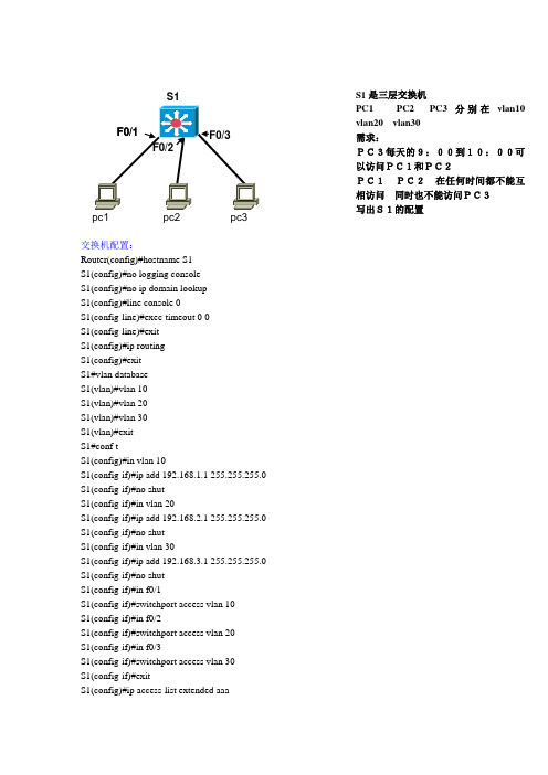
交换机配置:Router(config)#hostname S1S1(config)#no logging consoleS1(config)#no ip domain lookupS1(config)#line console 0S1(config-line)#exec-timeout 0 0S1(config-line)#exitS1(config)#ip routingS1(config)#exitS1#vlan databaseS1(vlan)#vlan 10S1(vlan)#vlan 20S1(vlan)#vlan 30S1(vlan)#exitS1#conf tS1(config)#in vlan 10S1(config-if)#ip add 192.168.1.1 255.255.255.0S1(config-if)#no shutS1(config-if)#in vlan 20S1(config-if)#ip add 192.168.2.1 255.255.255.0S1(config-if)#no shutS1(config-if)#in vlan 30S1(config-if)#ip add 192.168.3.1 255.255.255.0S1(config-if)#no shutS1(config-if)#in f0/1S1(config-if)#switchport access vlan 10S1(config-if)#in f0/2S1(config-if)#switchport access vlan 20S1(config-if)#in f0/3S1(config-if)#switchport access vlan 30S1(config-if)#exitS1(config)#ip access-list extended aaaS1pc1 pc2 pc3 S1是三层交换机 PC1 PC2 PC3分别在vlan10 vlan20 vlan30 需求: PC3每天的9:00到10:00可以访问PC1和PC2 PC1 PC2 在任何时间都不能互相访问 同时也不能访问PC3 写出S1的配置S1(config-ext-nacl)#permit ip 192.168.3.0 0.0.0.255 192.168.1.0 0.0.0.255 reflect bbb timeout 100 time-range cccS1(config-ext-nacl)#permit ip 192.168.3.0 0.0.0.255 192.168.2.0 0.0.0.255 reflect bbb timeout 100 time-range cccS1(config-ext-nacl)# exitS1(config)#ip access-list extended dddS1(config-ext-nacl)#evaluate bbbS1(config-ext-nacl)#exitS1(config)#time-range cccS1(config-time-range)#periodic daily 9:00 to 10:00S1(config-time-range)#in vlan 30S1(config-if)#ip access-group aaa inS1(config-if)#in vlan 10S1(config-if)#ip access-group ddd inS1(config-if)#in vlan 20S1(config-if)#ip access-group ddd inS1(config-if)#endS1#clock set 9:10:10 10 oct 2008注:自反列表(相当于动态列表)必须采用扩展命名列表,命名列表中的条件可以单条删除,但最好有备份实验总结:保证正常通信后配置ACL列表,挂接口的方向时一定要注意。

实验八:静态路由实验一、实验目的实验目的:1、了解静态路由配置的环境要求2、掌握静态路由的配置方法3、学会查看路由表,分析路由参数二、实验内容实验内容:1、配置所有PC的ip地址、子网掩码和网关地址2、配置路由器的B类静态路由3、设置路由器R1对路由器R2上的主机网络的地址转发到10.68.1.14、查看路由表,并进行连通性测试三、实验原理实验原理:通过配置所有PC的ip地址、子网掩码和网关地址和静态路由的目的地址、子网掩码、下一跳ip地址的配置实现不同网段之间的PC可以进行互相访问。
四、实验器材实验器材:2台路由器Router,4台PC,5根网线五、实验步骤实验步骤:第一步:建立拓扑,开启所有服务设备第二步:配置所有pc的ip地址、子网掩码和网关地址第三步:双击路由器R1进入命令视图界面,(sysname Rou-R1)修改名称第四步:(interface ethernet0/0/0)进入接口E0/0/0,并配置E0/0/0接口ip地址第五步:(int e0/0/1)进入接口内部端口E0/0/1,并配置E0/0/1接口ip地址第六步:(int s0/0/1)进入接口外部端口S0/0/1,并配置S0/0/1接口ip地址第七步:双击路由器R2进入命令视图界面,(sysname Rou-R2)修改名称第八步:重复第四步到第六步的操作完成接口E0/0/0、E0/0/1、S0/0/0的ip地址配置第九步:ping测试PC1与路由器的连能性第十步:设置从路由器R1到路由器R2的静态路由转发第十一步:设置从路由器R2到路由器R1的静态路由转发第十二步:查看路由表,并重新ping进行连通性测试六、实验结果(数据和图表)结论实验结果(数据和图表)拓扑模型配置4台PC地址配置内部端口E0/0/0接口ip地址配置内部端口E0/0/1接口ip地址配置外部端口S0/0/1接口ip地址由于在华为Ensp中同步串口的时钟速率波特率默认为64Kbps,所以此处不进行特别配置查看路由器R1当前内部接口E0/0/0、E0/0/1配置情况测试路由器R1与PC之间的连能性配置路由器R2:配置内部E0/0/0接口ip地址配置内部E0/0/1接口ip地址配置外部S0/0/0接口ip地址查看路由器R2当前内部接口E0/0/0、E0/0/1配置情况测试路由器R2与PC之间的连能性设置路由器R1上的10.70.0.0和10.71.0.0地址转发到路由器R1的10.68.1.1设置路由器R2上的地址10.65.0.0和10.66.0.0转发到路由器R2的10.68.1.2查看路由表R1的情况查看路由表R2的情况连通性测试七、结果分析与结论结果分析:在实验过程中,发现在进行连通性的检测时,我们在路由器R1上添加指定该网段的路由信息之后,为了使能够实现相互互通,就需要双向添加即同样的在路由器R2上也添加属于该网段的网段的信息,并且静态路由的命令是ip route 目的ip地址子网掩码下一跳ip地址,其中下一跳ip地址是静态路由的根本,没有下一跳地址我们的路由就根本到达不了我们想要去的网域。
《数据通信与计算机网络实验》实验报告实验八网络配置综合设计班级:xxxxxxxx学号:xxxxxx姓名:xxxxx案例3一公司总部与分部公网互联一、目标1、熟悉VLAN规和VLAN间路由2、熟悉路由的配置(rip或其他的路由都可以)。
3、熟悉acl配置4、熟悉NAT配置5、ip地址划分与拓扑结构设计二、场景1、某公司总部为一栋三层大楼,如图1所示,每层节点数量如图所示。
1 楼由人力资源部门占用,2 楼由 IT 部门占用,3 楼由销售部门占用。
所有部门必须能相互通信,但是同时又拥有自己独立的工作网络。
给定的IP地址范围是:192.168.X.0/24,根据实际情况划分子网(其中X为个人的学号序号)。
图1 公司总部2、该公司有一个分支机构离公司总部不远,该分支机构为一个二层小楼如图2所示,1 楼由研发部门占用,2 楼由行政部门占用,所有部门必须能相互通信,但是同时又拥有自己独立的工作网络。
给定的IP地址范围是:192.168.X+1.0/24,根据实际情况划分子网(其中X为个人的学号序号)。
图2 分支机构3、公司内部无网络设备,全部设备需新采购,总部与分支机构之间通过专网相连,但都能访问公网,你是网络管理员,必须设计公司总部、分支机构与公网三者之间的联网方案,以便为所有公司员工提供高速的内部网络和INTERNET服务。
三、步骤第 1 步: 设计拓扑。
图3 网络拓扑图设计第 2 步: 制定 VLAN 方案。
a. 为所有部门设计 VLAN 的名称和编号。
b. 包括一个管理 VLAN,可以命名为“管理”或“本征”,根据您的选择编号。
c. 使用 IPv4作为你的 LAN 编址方案,也必须使用 VLSM。
d. IP地址与VLAN分配,以下为示例表格。
地址表VLAN与端口分配(交换机1)VLAN与端口分配(交换机2)VLAN与端口分配(交换机3)VLAN与端口分配(交换机4)第 3 步: 设计一个图来展示你的 VLAN 设计和地址方案。
实验八——路由器基本配置一、实验目的掌握对路由器进行基本配置的方法二、实验预习内容1.路由器有哪两种管理方式?答:(1)带外管理:通过交换机端口Console管理交换机属于带外管理。
(2)带内管理:通过远程Telnet,拨号连接等方式属于带内管理。
2.路由器配置的命令行有哪几种操作模式答:(1)router.>用户模式:是进入交换机后得到的第一个模式,在该模式下可以查看交换机的软件硬件版本信息,并进行简单的配置(2)router.#特权模式:由户模式进入的下一级模式,在该模式下可以对交换机的配置文件进行管理,查看交换机的配置信息。
(3)router.(cofig)#全局配置模式:属于特权模式的下一级模式,在该模式下可以对交换机的全局参数(主机名,登陆信息等)(4) router.(cofig-if)#端口配置模式:可以对端口的速率工作方式进行配置管理。
3.为路由器端口配置IP地址的命令格式是什么?答:1.进入特权模式:enable(en).2.进入全局配置模式configure terminal(conf t)3进入端口配置模式interface fastethernet 0/1 (int fa 0/1)4.返回上一级命令模式:exit。
5.直接返回到特权模式:end4.如何用命令开启路由器端口?答:在路由器配置窗口中选择fastethernet 0/0端口,点击开启5、如何设置路由器可远程登录?答:在用户模式下,先后输入en、000和conf t,进入全局配置模式。
输入line vty 0 4.按回车键,设置5各终端可以进行远程登录。
三、实验内容某公司进入一批路由器,以网络管理员身份对路由器进行配置。
然后设置网络管理员在远端时可以通过远程登录方式登录路由器进行配置。
(1)设置路由器名称为Myrouter;(2)设置进入特权模式密码为000;(3)设置五个终端可以远程访问;(4)设置远程登录密码为aaa;(5)在终端上进行远程登录;(6)查看配置信息;四、实验步骤1.打开Cisco Packet Tracer软件,添加一个路由器和两个终端。
路由器基本配置实验报告路由器基本配置实验报告一:实验目的本实验旨在掌握路由器基本配置的操作步骤,包括IP地址配置、路由协议配置等内容。
二:实验环境1. 实验设备:一台路由器2. 实验软件:路由器配置工具三:实验步骤1. 网络拓扑设计在实验室环境中,设置一个简单的拓扑结构,包括一个局域网和一个广域网。
局域网内有两台主机,广域网通过路由器与局域网连接。
2. 路由器基本设置1) 连接路由器将计算机与路由器通过网线连接,并确认连接正常。
2) 登录路由器打开配置工具,输入路由器的IP地址,并输入管理员账号密码登录路由器的管理界面。
3) 修改管理员密码在路由器管理界面中,找到系统设置选项,修改管理员密码以保证安全性。
4) 配置设备名称在路由器管理界面中,找到设备名称设置选项,将设备名称修改为用户定义的名称。
5) 配置IP地址在路由器管理界面中,找到接口配置选项,为路由器的各个接口配置合适的IP地址。
6) 保存配置在路由器管理界面中,找到配置保存选项,保存已经修改的配置。
3. 路由协议配置1) 静态路由配置在路由器管理界面中,找到静态路由设置选项,为路由器配置静态路由项,使得路由器能够正确地转发数据包。
2) 动态路由配置在路由器管理界面中,找到动态路由设置选项,选择适合的路由协议并进行配置,实现路由器的动态路由功能。
四:实验结果经过以上步骤的操作,成功完成了路由器基本配置。
通过测试,发现路由器能够正确地转发数据包,并且实现了动态路由功能。
五:本文档涉及附件本文档没有涉及附件。
六:法律名词及注释1. IP地址:Internet Protocol Address的缩写,指互联网协议地址。
每台连接到互联网的设备都需要拥有唯一的IP地址,用于标识设备在网络中的位置。
2. 静态路由:由网络管理员手动配置的路由,其中每条路由包含目标网络和下一跳路由器的信息。
3. 动态路由:由路由器通过某种路由协议自动学习和更新的路由信息,能够根据网络拓扑的变化进行自适应调整。
实验报告-路由器的基本配置实验报告-路由器的基本配置1、实验目的本实验旨在掌握路由器的基本配置方法,包括IP地质的配置、静态路由的配置、NAT的配置等。
2、实验设备本实验所使用的设备如下:- 1台路由器(型号:)- 1台电脑- 网线若干3、实验步骤3.1 路由器的物理连接将路由器与电脑通过网线连接,确保连接稳定。
3.2 路由器的基本配置3.2.1 登录路由器打开浏览器,在地质栏中输入路由器的IP地质(如192.168.1.1),按下回车键进入路由器的登录界面。
输入正确的用户名和密码,登录。
3.2.2 配置IP地质在路由器的管理界面中,找到网络设置选项。
根据实际网络环境的要求,配置路由器的IP地质。
局域网IP地质.192.168.1.1子网掩码.255.255.255:03.2.3 配置静态路由在路由器的管理界面中,找到路由配置选项。
根据实际网络环境的要求,配置静态路由表,实现不同网络之间的互联。
示例:目标网络.192.168.2:0下一跳.192.168.1.23.2.4 配置NAT在路由器的管理界面中,找到NAT配置选项。
根据实际网络环境的要求,配置NAT,实现内网IP地质转换为公网IP地质访问互联网。
示例:内网IP地质.192.168.1:0公网IP地质:X:X:X:X4、实验结果经过配置后,路由器的基本功能得到了实现。
通过配置IP地质,网络设备可以彼此通信。
通过配置静态路由和NAT,不同网络之间可以互联,并且内网设备可以访问互联网。
5、实验心得本实验中,我深入了解了路由器的基本配置方法,通过实际操作,收获了一定的实验经验。
附件:无法律名词及注释:1、IP地质:Internet Protocol Address的缩写,是指互联网协议地质,用于给网络中的设备分配唯一的标识。
IP地质分为公网IP地质和私网IP地质两种类型。
2、子网掩码:Subnet Mask的缩写,用于划分IP地质的网络和主机部分。
实验八路由器路由协议配置目录一、实验目的1二、静态路由配置1三、RIP路由配置3四、OSPF路由配置5一、实验目的1、掌握静态路由配置;2、掌握RIP路由配置;3、掌握RIP路由配置4、掌握OSPF路由配置二、静态路由配置(一)基本知识◆在配置静态路由之前,需完成以下任务:1、配置相关接口的物理参数2、配置相关接口的链路层属性3、配置相关接口的IP地址在配置静态路由时,如果先指定下一跳地址,然后将该地址配置为本地接口(如以太网接口、VLAN接口等)的IP地址,静态路由不会生效。
如果在配置静态路由时没有指定优先级,就会使用缺省优先级。
重新设置缺省优先级后,新设置的缺省优先级仅对新增的静态路由有效。
设置静态路由的Tag值,可以在路由策略中根据Tag值对路由进行灵活的控制。
静态路由显示和维护在完成上述配置后,在任意视图下执行display命令查看静态路由配置的运行情况并检验配置结果。
在系统视图下执行delete命令可以删除配置的所有静态路由。
操作命令查看当前的配置文件信息display current-configuration查看IP路由表摘要信息display ip routing-table查看IP路由表详细信息display ip routing-table verbose查看静态路由表信息display ip routing-table protocol static [ inactive | verbose ]删除所有静态路由delete [ vpn-instance vpn-instance-name ] static-routes all(二)组网需求路由器各接口及主机的IP地址和掩码如下图所示。
要求采用静态路由,使图中任意两台主机之间都能互通。
(三)组网图静态路由配置组网图(四)配置步骤1、配置各接口的IP地址:自行配置(与交换机类似),例如[H3C]interface e 0/0[H3C-Ethernet0/0]ip address 192.168.1.1 24[H3C]interface serial3/0[H3C-serial3/0]ip address 192.168.2.1 242、配置静态路由# 进入系统视图。
<RouterA> system-view# 在RouterA上配置缺省路由。
[RouterA] ip route-static 0.0.0.0 0.0.0.0 1.1.4.2# 在RouterB上配置两条静态路由。
[RouterB] ip route-static 1.1.1.0 255.255.255.0 1.1.4.1[RouterB] ip route-static 1.1.3.0 255.255.255.0 1.1.4.6# 在RouterC上配置缺省路由。
[RouterB] ip route-static 0.0.0.0 0.0.0.0 1.1.4.53、配置主机配置主机PC1的缺省网关为1.1.1.1,主机PC2的缺省网关为1.1.2.1,主机PC3的缺省网关为1.1.3.1。
4、查看配置结果# 显示RouterA的IP路由表。
(注意:查看RouterB、C的配置结果类似)[RouterA] display ip routing-tableRouting Tables: PublicDestinations : 8 Routes : 8Destination/Mask Proto Pre Cost NextHop Interface0.0.0.0/0 Static 60 0 1.1.4.2 Serial3/01.1.1.0/24 Direct 0 0 1.1.1.1 Ethernet1/01.1.1.1/32 Direct 0 0 127.0.0.1 InLoopBack01.1.4.0/30 Direct 0 0 1.1.4.1 Serial3/01.1.4.1/32 Direct 0 0 127.0.0.1 InLoopBack01.1.4.2/32 Direct 0 0 1.1.4.2 Serial3/0127.0.0.0/8 Direct 0 0 127.0.0.1 InLoopBack0127.0.0.1/32 Direct 0 0 127.0.0.1 InLoopBack0# 使用Ping命令验证连通性。
[RouterA] ping 1.1.3.1PING 1.1.3.1: 56 data bytes, press CTRL_C to breakReply from 1.1.3.1: bytes=56 Sequence=1 ttl=254 time=62 msReply from 1.1.3.1: bytes=56 Sequence=2 ttl=254 time=63 msReply from 1.1.3.1: bytes=56 Sequence=3 ttl=254 time=63 msReply from 1.1.3.1: bytes=56 Sequence=4 ttl=254 time=62 msReply from 1.1.3.1: bytes=56 Sequence=5 ttl=254 time=62 ms--- 1.1.3.1 ping statistics ---5 packet(s) transmitted5 packet(s) received0.00% packet lossround-trip min/avg/max = 62/62/63 ms# 使用tracert命令验证连通性。
[RouterA] tracert 1.1.3.1traceroute to 1.1.3.1(1.1.3.1) 30 hops max,40 bytes packet1 1.1.4.2 31 ms 32 ms 31 ms2 1.1.4.6 62 ms 63 ms 62 ms三、RIP路由配置(一)组网需求如下图所示,要求在RouterA和RouterB的所有接口上使能RIP,并使用RIP-2进行网络互连。
(二)组网图(三)配置步骤1、配置各接口的IP地址(略)2、配置RIP基本功能# 配置RouterA。
<RouterA> system-view[RouterA] rip[RouterA-rip-1] network 192.168.1.0[RouterA-rip-1] network 172.16.0.0[RouterA-rip-1] network 172.17.0.0# 配置RouterB。
<RouterB> system-view[RouterB] rip[RouterB-rip-1] network 192.168.1.0[RouterB-rip-1] network 10.0.0.0# 查看RouterA的RIP路由表。
[RouterA] display rip 1 routeRoute Flags: R - RIP, T - TRIPP - Permanent, A - Aging, S - Suppressed, G - Garbage-collect--------------------------------------------------------------------------Peer 192.168.1.2 on Serial3/0Destination/Mask Nexthop Cost Tag Flags Sec10.0.0.0/8 192.168.1.2 1 0 RA 14从路由表中可以看出,RIP-1发布的路由信息使用的是自然掩码。
配置RIP的版本# 在RouterA上配置RIP-2。
[RouterA] rip[RouterA-rip-1] version 2# 在RouterB上配置RIP-2。
[RouterB] rip[RouterB-rip-1] version 2# 查看RouterA的RIP路由表。
[RouterA] display rip 1 routeRoute Flags: R - RIP, T - TRIPP - Permanent, A - Aging, S - Suppressed, G - Garbage-collect--------------------------------------------------------------------------Peer 192.168.1.2 on S erial3/0Destination/Mask Nexthop Cost Tag Flags Sec10.2.1.0/24 192.168.1.2 1 0 RA 3210.1.1.0/24 192.168.1.2 1 0 RA 32从路由表中可以看出,RIP-2发布的路由中带有更为精确的子网掩码信息。
&说明:由于RIP路由信息的老化时间较长,所以在配置RIP-2版本后的一段时间里,路由表中可能还会存在RIP-1的路由信息。
四、OSPF路由配置(一)组网需求◆所有的路由器都运行OSPF,并将整个自治系统划分为3个区域。
◆其中RouterA和RouterB作为ABR来转发区域之间的路由。
◆配置完成后,每台路由器都应学到AS的到所有网段的路由。
(二)组网图(三)配置步骤1、配置各接口的IP地址(略)2、配置OSPF基本功能# 配置RouterA。
<RouterA> system-view[RouterA] ospf[RouterA-ospf-1] area 0[RouterA-ospf-1-area-0.0.0.0] network 192.168.0.0 0.0.0.255[RouterA-ospf-1-area-0.0.0.0] quit[RouterA-ospf-1] area 1[RouterA-ospf-1-area-0.0.0.1] network 192.168.1.0 0.0.0.255[RouterA-ospf-1-area-0.0.0.1] quit[RouterA-ospf-1] quit# 配置RouterB。
<RouterB> system-view[RouterB] ospf[RouterB-ospf-1] area 0[RouterB-ospf-1-area-0.0.0.0] network 192.168.0.0 0.0.0.255[RouterB-ospf-1-area-0.0.0.0] quit[RouterB-ospf-1] area 2[RouterB-ospf-1-area-0.0.0.2] network 192.168.2.0 0.0.0.255[RouterB-ospf-1-area-0.0.0.2] quit[RouterB-ospf-1] quit# 配置RouterC。