Perceptually-Friendly H.264AVC Video Coding Based on Foveated Just-Noticeable-Distortion Model
- 格式:pdf
- 大小:6.10 MB
- 文档页数:14
Preferred Contact MethodIntroductionIn this digital age, communication has become easier and more convenient than ever before. With a multitude of contact methods available, it is important to determine the preferred method for effective and efficient communication. This article will explore the various contact methods and discuss the factors that influence individuals’ preferences.Factors Influencing Preferred Contact Method1. Accessibility•Availability of technology: The level of access to smartphones, computers, and the internet can grea tly influence an individual’s preferred contact method.•Ease of use: Some contact methods may require a certain level of technical knowledge or skills, which can impact an individual’schoice.2. Urgency•Time sensitivity: Depending on the urgency of the message, individuals may prefer a contact method that allows for immediate communication, such as phone calls or instant messaging.•Response time: If a quick response is expected, individuals may choose a contact method that is known for prompt replies.3. Privacy and Security•Confidentiality: For sensitive information, individuals may prefer contact methods that ensure privacy and security, such asencrypted messaging apps or face-to-face meetings.•Data protection: Concerns about data breaches and online security may influence an individual’s choice of contact method.4. Personal Preference•Communication style: Some individuals may prefer face-to-face interactions, while others may feel more comfortable communicating through written messages.•Personal habits: Factors like introversion or extroversion, preference for written or verbal communication, and individualhabits can play a role in determining the preferred contact method. Types of Contact Methods1. Phone Calls•Pros:–Real-time communication: Phone calls allow for immediate interaction, enabling quick clarification and discussion.–Tone and emotion: Verbal communication allows for theconveyance of tone and emotion, which can enhanceunderstanding.•Cons:–Availability: Phone calls require both parties to beavailable at the same time, which may not always beconvenient.–Intrusion: Unsolicited phone calls can be intrusive and disruptive.2. Email•Pros:–Asynchronous communication: Emails can be sent and received at any time, allowing for flexibility in communication.–Documentation: Emails provide a written record ofconversations, which can be useful for reference andclarification.•Cons:–Delayed response: Emails may not receive an immediateresponse, leading to potential delays in communication.–Spam and clutter: Email inboxes can easily become cluttered with spam or irrelevant messages, making important emailsharder to find.3. Instant Messaging•Pros:–Real-time interaction: Instant messaging allows for quick back-and-forth communication, similar to a conversation.–Multi-media sharing: Users can easily share files, images, and videos through instant messaging platforms.•Cons:–Distractions: Instant messaging can be distracting, with constant notifications and the temptation to engage in non-work-related conversations.–Misinterpretation: Without visual cues, written messages can be misinterpreted, leading to misunderstandings.4. Face-to-Face Meetings•Pros:–Personal connection: Face-to-face meetings allow for a deeper level of personal connection and relationshipbuilding.–Non-verbal communication: Body language and facialexpressions can enhance understanding and convey emotions.•Cons:–Time-consuming: Face-to-face meetings often require travel time and coordination, which can be impractical for remoteor geographically distant individuals.–Scheduling conflicts: Finding a mutually convenient time fora face-to-face meeting can be challenging.ConclusionDetermining the preferred contact method depends on various factors, including accessibility, urgency, privacy, and personal preference. Each contact method has its own advantages and disadvantages, and individuals may choose different methods for different situations. Ultimately, effective communication relies on understanding and respecting each other’s preferred contact method to ensure successful interaction.。
The ITU-T published J.144, a measurement of quality of service, for the transmission of television and other multimedia digital signals over cable networks. This defines the relationship between subjective assessment of video by a person and objective measurements taken from the network.The correlation between the two are defined by two methods:y Full Reference (Active) – A method applicable when the full reference video signal is available, and compared with the degraded signal as it passes through the network.y No Reference (Passive) – A method applicable when no reference video signal or informationis available.VIAVI believes that a combination of both Active and Passive measurements gives the correct blendof analysis with a good trade off of accuracy and computational power. T eraVM provides both voice and video quality assessment metrics, active and passive, based on ITU-T’s J.144, but are extended to support IP networks.For active assessment of VoIP and video, both the source and degraded signals are reconstituted from ingress and egress IP streams that are transmitted across the Network Under T est (NUT).The VoIP and video signals are aligned and each source and degraded frame is compared to rate the video quality.For passive measurements, only the degraded signal is considered, and with specified parameters about the source (CODEC, bit-rate) a metric is produced in real-time to rate the video quality.This combination of metrics gives the possibility of a ‘passive’ but lightweight Mean Opinion Score (MOS) per-subscriber for voice and video traffic, that is correlated with CPU-expensive but highly-accurate ‘active’ MOS scores.Both methods provide different degrees of measurement accuracy, expressed in terms of correlation with subjective assessment results. However, the trade off is the considerable computation resources required for active assessment of video - the algorithm must decode the IP stream and reconstitute the video sequence frame by frame, and compare the input and outputnframesto determine its score. The passive method is less accurate, but requires less computing resources. Active Video AnalysisThe active video assessment metric is called PEVQ– Perceptual Evaluation of Video Quality. PEVQ provides MOS estimates of the video quality degradation occurring through a network byBrochureVIAVITeraVMVoice, Video and MPEG Transport Stream Quality Metricsanalysing the degraded video signal output from the network. This approach is based on modelling the behaviour of the human visual tract and detecting abnormalities in the video signal quantified by a variety of KPIs. The MOS value reported, lies within a range from 1 (bad) to 5 (excellent) and is based on a multitude of perceptually motivated parameters.T o get readings from the network under test, the user runs a test with an video server (T eraVM or other) and an IGMP client, that joins the stream for a long period of time. The user selects the option to analysis the video quality, which takes a capture from both ingress and egress test ports.Next, the user launches the T eraVM Video Analysis Server, which fetches the video files from the server, filters the traffic on the desired video channel and converts them into standard video files. The PEVQ algorithm is run and is divided up into four separate blocks.The first block – pre-processing stage – is responsible for the spatial and temporal alignment of the reference and the impaired signal. This process makes sure, that only those frames are compared to each other that also correspond to each other.The second block calculates the perceptual difference of the aligned signals. Perceptual means that only those differences are taken into account which are actually perceived by a human viewer. Furthermore the activity of the motion in the reference signal provides another indicator representing the temporal information. This indicator is important as it takes into account that in frame series with low activity the perception of details is much higher than in frame series with quick motion. The third block in the figure classifies the previously calculated indicators and detects certain types of distortions.Finally, in the fourth block all the appropriate indicators according to the detected distortions are aggregated, forming the final result ‒ the mean opinion score (MOS). T eraVM evaluates the quality of CIF and QCIF video formats based on perceptual measurement, reliably, objectively and fast.In addition to MOS, the algorithm reports:y D istortion indicators: For a more detailed analysis the perceptual level of distortion in the luminance, chrominance and temporal domain are provided.y D elay: The delay of each frame of the test signal related to the reference signal.y Brightness: The brightness of the reference and degraded signal.y Contrast: The contrast of the distorted and the reference sequence.y P SNR: T o allow for a coarse analysis of the distortions in different domains the PSNR is provided for theY (luminance), Cb and Cr (chrominance) components separately.y Other KPIs: KPIs like Blockiness (S), Jerkiness, Blurriness (S), and frame rate the complete picture of the quality estimate.Passive MOS and MPEG StatisticsThe VQM passive algorithm is integrated into T eraVM, and when required produces a VQM, an estimation of the subjective quality of the video, every second. VQM MOS scores are available as an additional statistic in the T eraVM GUI and available in real time. In additionto VQM MOS scores, MPEG streams are analysed to determine the quality of each “Packet Elementary Stream” and exports key metrics such as Packets received and Packets Lost for each distinct Video stream within the MPEG Transport Stream. All major VoIP and Video CODECs are support, including MPEG 2/4 and the H.261/3/3+/4.2 TeraVM Voice, Video and MPEG Transport Stream Quality Metrics© 2020 VIAVI Solutions Inc.Product specifications and descriptions in this document are subject to change without notice.tvm-vv-mpeg-br-wir-nse-ae 30191143 900 0620Contact Us +1 844 GO VIAVI (+1 844 468 4284)To reach the VIAVI office nearest you, visit /contacts.VIAVI SolutionsVoice over IP call quality can be affected by packet loss, discards due to jitter, delay , echo and other problems. Some of these problems, notably packet loss and jitter, are time varying in nature as they are usually caused by congestion on the IP path. This can result in situations where call quality varies during the call - when viewed from the perspective of “average” impairments then the call may appear fine although it may have sounded severely impaired to the listener. T eraVM inspects every RTP packet header, estimating delay variation and emulating the behavior of a fixed or adaptive jitter buffer to determine which packets are lost or discarded. A 4- state Markov Model measures the distribution of the lost and discarded packets. Packet metrics obtained from the Jitter Buffer together with video codec information obtained from the packet stream to calculate a rich set of metrics, performance and diagnostic information. Video quality scores provide a guide to the quality of the video delivered to the user. T eraVM V3.1 produces call quality metrics, includinglistening and conversational quality scores, and detailed information on the severity and distribution of packet loss and discards (due to jitter). This metric is based on the well established ITU G.107 E Model, with extensions to support time varying network impairments.For passive VoIP analysis, T eraVM v3.1 emulates a VoIP Jitter Buffer Emulator and with a statistical Markov Model accepts RTP header information from the VoIP stream, detects lost packets and predicts which packets would be discarded ‒ feeding this information to the Markov Model and hence to the T eraVM analysis engine.PESQ SupportFinally , PESQ is available for the analysis of VoIP RTP Streams. The process to generate PESQ is an identical process to that of Video Quality Analysis.。
第一部分:5.1 5.1环绕立体声(channel)value 通道值10/8 bit black point 黑点参数10/8 bit white point 白点参数3D glasses 三维眼镜3D motion 3D过渡3D view 三维查看4 color gradient 四色渐变5.1 mixdown type 5.1混音类型abort capture on dropped frames 丢失帧则中断采集absorption 吸收action safe area 动作安全区域activate 激活add 添加add anchor point tool 添加节点工具add track 添加轨道add/remove keyframes 添加/删除关键帧additive dissolve 附加溶解adjust 调整adobe bridge 媒体管理软件adobe dynamic link Adobe动态链接adobe media encoder Adobe媒体编码器advanced gif options 高级选项align objects 对齐对象alignment 对齐选项all marker 所有标记all scopes 全部显示alpha alpha通道alpha adjust alpha调整alpha blurriness alpha通道模糊alpha glow Alpha辉光alpha glow settings Alpha辉光设置alpha scale alpha 缩放amount 数量amount of noise 噪点数量amount to decolor 删除量amount to equalize 重新分布亮度值的程度amount to tint 指定色彩化的数量amplitude 振幅anchor 定位点anchor 交叉anchor point 定位点angle 角度antialias 抗锯齿antialiasing 反锯齿anti-flicker filter 去闪烁滤镜append style library 加载样式库apply audio transition 应用音频转换apply phase map to alpha 应用相位图到alpha通道apply style 应用样式apply style color only 仅应用样式颜色apply style with font size 应用样式字体大小apply video transition 应用视频转换arc tool 扇形工具area type tool 水平段落文本工具arithmetic 计算arrange 排列aspect 比例assume this frame rate 手动设置帧速率audio 音频audio effects 音频特效audio gain 音频增益audio hardware 音频硬件audio in 音频入点audio master meters 音频主电平表audio mixer 混音器audio options 音频选项audio out 音频出点audio output mapping 音频输出映射audio previews 音频预演audio samples 音频采样audio transitions 音频转换audio transitions default duration 默认音频切换持续时间auto black level 自动黑色auto color 自动色彩auto contrast 自动对比度auto levels 自动色阶auto save 自动保存auto white level 自动白色auto-generate dvd markers 自动生成DVD标签automatch time 自动匹配时间automate to sequence 序列自动化automatic quality 自动设置automatically save every 自动保存时间automatically save projects 自动保存average pixel colors 平均像素颜色background color 背景色balance 平衡balance angle 白平衡角度balance gain 增加白平衡balance magnitude 设置平衡数量band slide 带形滑行band wipe 带形擦除bandpass 带通滤波barn doors 挡光板bars and tone 彩条色调栅栏based on current title 基于当前字幕based on template 基于字幕模板baseline shift 基线basic 3D 基本三维bass 低音batce capture 批量采集bend 弯曲bend settings 弯曲设置best 最佳质量between 两者bevel 斜面填充bevel alpha alpha导角bevel edges 边缘倾斜bin 文件夹black & white 黑白black input level 黑色输入量black video 黑屏blend 混合blend with layer 与层混合blend with original 混合来源层blending 混合选项blending mode 混合模式block dissolve 块面溶解block width/block height 板块宽度和板块高度blue 蓝色blue blurriness 蓝色通道模糊blue screen key 蓝屏抠像blur & sharpen 模糊与锐化blur center 模糊中心blur dimensions 模糊方向blur dimensions 模糊维数blur length 模糊程度blur method 模糊方式blurriness 模糊强度blurs 斜面边框boost light 光线亮度border 边界bottom 下branch angle 分支角度branch seg. Length 分支片段长度branch segments 分支段数branch width 分支宽度branching 分支brightness 亮度brightness & contrast 亮度与对比度bring forward 提前一层bring to front 放在前层broadcast colors 广播级颜色broadcast locale 指定PAL或NTSC两种电视制式browse 浏览brush hardness 画笔的硬度brush opacity 画笔的不透明度brush position 画笔位置brush size 画笔尺寸brush spacing 绘制的时间间隔brush strokes 画笔描边brush time properties 应用画笔属性(尺寸和硬度)到每个笔触段或者整个笔触过程calculations 计算器camera blur 镜头模糊camera view 相机视图camera view settings 照相机镜头设置capture 采集capture format 采集格式capture settings 采集设置cell pattern 单元图案center 中心center at cut 选区中间切换center gradient 平铺center merge 中心融合center of sphere 球体中心center peel 中心卷页center split 中心分裂center texture 纹理处于中心center X 中心 Xcenter Y 中心 Ychange by 颜色转换的执行方式change color 转换颜色change to color 转换到颜色channel 通道channel blur 通道模糊channel map 通道映射图channel map settings 通道映射图设置channel mixer 通道混合channel volume 通道音量checker wipe 方格擦除checkerboard 棋盘格choose a texture image 选择纹理图片chroma 浓度chroma key 色度键chroma max 最小值chroma min 最大值cineon converter 转换cineon文件circle 圆形clear 清除clear all dvd markers 清除所有DVD标签clear clip marker 清除素材标记clear dvd marker 清除DVD标记clear sequence marker 清除序列标记clip 素材clip gain 修剪增益clip name 存放名称clip notes 剪辑注释clip overlap 重叠时间clip result values 用于防止设置颜色值的所有功能函数项超出限定范围clip sample 原始画面clip speed/duration 片段播放速度/持续时间clip/speed/duration 片段/播放速度/持续时间clipped corner rectangletool 尖角矩形工具clipped face 简略表面clipping 剪辑clock wipe 时钟擦除clockwise 顺时针close 关闭color 色彩color balance(HLS) 色彩平衡HLScolor balance(RGB)色彩平衡RGBcolor correction 色彩校正color correction layer 颜色校正层color correction mask 颜色校正遮罩color depth 色彩深度color emboss 色彩浮雕color influence 色彩影响color key 色彩键color match 色彩匹配color matte 颜色底纹color offset 色彩偏移color offset settings 色彩偏移设置color pass 色彩通道color pass settings 色彩过滤设置color picker 颜色提取color replace 色彩替换color replace settings 颜色替代设置color stop color 色彩设置color stop opacity 色彩不透明度color to change 颜色变换color to leave 保留色彩color tolerance 颜色容差colorze 颜色设置complexity 复杂性composite in back 使用alpha通道从后向前叠加composite in front 使用alpha 通道从前向后叠加composite matte withoriginal 指定使用当前层合成新的蒙版,而不是替换原素材层composite on original 与源图像合成composite rule 混合通道composite using 设置合成方式composite video 复合视频composition 合成项目compound arithmetic 复合算法compressor 压缩constant gain 恒定功率constant power 恒定增益contrast 对比度contrast level 对比度的级别convergence offset 集中偏移conversion type 转换类型convert anchor point tool 节点转换工具convolution kernel 亮度调整convolution kernel settings 亮度调整设置copy 复制core width 核心宽度corner 交叉corner pin 边角count 数量counterclockwise 逆时针counting leader 计数向导crawl 水平爬行crawl left 从右向左游动crawl right 从左向右游动crop 裁剪cross dissolve 淡入淡出cross stretch 交叉伸展cross zoom 十字缩放crossfade 淡入淡出cube spin 立体旋转cue blip at all second starts 每秒开始时提示音cue blip on 2 倒数第2秒时提示音cue blip on out 最后计数时提示音cursor 光标curtain 窗帘curvature 曲率custom settings 自定义custom setup 自定义设置cut 剪切cutoff 对比cyan 青色cycle (in revolutions)指定旋转循环cycle evolution 循环设置第二部分:decay 组合素材强度减弱的比例default 默认default crawl 默认水平滚动default roll 默认垂直滚动default sequence 默认序列设置default still 默认静态defringing 指定颜色通道delay 延时delete anchor point tool 删除节点工具delete render files 删除预览文件delete style 删除样式delete tracks 删除轨道delete workspace 删除工作界面denoiser 降噪density 密度depth 深度deselect all 取消全选detail amplitude 细节振幅detail level 细节级别device control 设备控制devices 设备diamond 菱形difference matte key 差异抠像dip to black 黑色过渡direct 直接direction 角度directional blur 定向模糊directional lights 平行光disperse 分散属性displace 位移displacement 转换display format 时间显示格式display mode 显示模式dissolve 溶解distance 距离distance to image 图像距离distort 扭曲distribute objects 分布对象dither dissolve 颗粒溶解doors 关门down 下draft 草图draft quality 草稿质量drop face 正面投影drop shadow 阴影duplicate 副本duplicate style 复制样式duration 持续时间dust & scratches 灰尘噪波dvd layout DVD布局dynamics 动态echo 重复echo operator 重复运算器echo time 重复时间edge 边缘edge behavior 设置边缘edge color 边缘颜色edge feather 边缘羽化edge sharpness 轮廓的清晰度edge softness 柔化边缘edge thickness 边缘厚度edge thin 边缘减淡edge type 边缘类型edit 编辑edit dvd marker 编辑DVD标记edit in adobe audition 用adobe audition编辑edit in adobe photoshop 用adobe photoshop编辑edit original 初始编辑edit sequence marker 编辑序列标记edit subelip 编辑替代素材editing 编辑模式editing mode 编辑模式effect controls 特效控制effects 特效eight-point garbage matte 八点无用信号遮罩eliminate 去除填充ellipse 椭圆ellipse tool 椭圆形工具embedding options 嵌入选项emboss 浮雕enable 激活end at cut 结束处切换end color 终点颜色end of ramp 渐变终点end off screen 从幕内滚出end point 结束点EQ 均衡器equalize 均衡events 事件窗口evolution 演变evolution options 演变设置exit 退出expander 扩展export 输出export batch list 批量输出列表export for clip notes 导出素材记录export frame 输出帧export frame settings 输出帧设置export movie 输出影片export movie settings 输出影片设置export project as aaf 按照AAF 格式输出项目export to DVD 输出到DVDextended character 扩展特性extract 提取extract settings 提取设置eyedropper fill 滴管填充face 表面facet 平面化fade 淡化fade out 淡出fast blur 快速模糊fast color corrector 快速校正色彩feather 羽化feather value 羽化的强度feedback 回馈field interpolate 插入新场field options 场设置fields 场设置file 文件文件格式for 文件信息fill 填充fill alpha channel 填充alpha 通道fill color 填充颜色fill key 填充键fill left 填充左声道fill point 填充点fill right 填充右声道fill selector 填充选择fill type 填充类型find 查找find edges 查找边缘first object above 第一对象上fit 自动fixed endpoint 固定结束点flare brightness 光晕亮度flare center 光晕中心flip over 翻页flip with object 翻转纹理focal length 焦距fold up 折叠font 字体font browser 字体浏览器font size 字号大小format 格式four-point garbage matte 四角无用信号遮罩fractal influence 不规则影响程度frame blend 帧混合frame blending 帧混合frame hold 帧定格frame rate 帧速率frame size 帧尺寸frames 逐帧显示funnel 漏斗gamma 调整gamma还原曲线gamma correction gamma修正gamma correctionsettings gamma修正设置gaussian blur 高斯模糊gaussian sharen 高斯锐化general 常规generate batch log on unsuccessful completion 生成批处理文件get properties for 获得属性ghost 阴影填充ghosting 重影glow 辉光go to clip marker 到素材标记点go to dvd marker 到DVD标记点go to next keyframe 转到下一关键帧go to previous keyframe 转到上一关键帧go to sequence marker 到序列标记点good 好GPU effects GPU特效GPU transitions GPU转场效果gradient layer 选择使用哪个渐变层进行参考gradient placement 设置渐变层的放置gradient wipe 渐变擦拭grain size 颗粒大小gray 灰色green 绿色green blurriness 绿色通道模糊green channels 绿色通道green screen key 绿屏抠像grid 网格group 群组height 高度help 帮助hi damp 高频阻尼high 高highest quality 最高质量highlight color 高光颜色highlight opacity 高光不透明度highlight rolloff 高光重算highlights 高光highpass 高通滤波history 历史horizontal 水平方向horizontal and vertical 水平和垂直方向horizontal blocks 水平方格horizontal center 水平居中horizontal decentering 水平偏移horizontal flip 水平翻转horizontal hold 水平保持horizontal prism fx 水平方向扭曲程度how to make color safe 实现“安全色”的方法how to use help 使用帮助hue 色调hue balance and angle 色调平衡和角度hue transform 色相调制if layer size differ 混合层的位置ignore alpha 忽视通道ignore audio 忽略音频ignore audio effects 忽略音频效果特效ignore options 忽略选项ignore video 忽略视频image control 图像控制image mask 图像遮罩image matte key 图像遮罩抠像import 导入import after effects composition 导入after effects 合成import batch list 批量导入列表import clip notes comments 导入素材记录import image as logo 导入图像为标志import recent file 最近导入的文件in 入点in and out around selection 入点和出点间选择individual parameters 特定参数info 信息inner strokes 内描边inport recent file 最近打开过的文件input channel 导入频道input levels 输入级别input range 输入范围insert 插入insert edit 插入编辑insert logo 插入标志insert logo into text 插入标志图到正文inset 插入切换inside color 内部颜色intensity 强度interlace upper L lower R 左右隔行交错interpolation 插入值interpret footage 解释影片invert 反转invert alpha 反转invert circle 反转圆环invert color correctionmask 设置是否将颜色校正遮罩反向invert composite 反转通道invert fill 反转填充invert grid 反转网格invert matte 反转蒙版层的透明度iris 划像iris box 盒子划像iris cross 十字划像iris diamond 钻石形划像iris points 四角划像iris round 圆形划像iris shapes 菱形划像iris star 五角星划像jitter 躁动kerning 字间距key 键控key color 键控颜色key out safe 将安全颜色透明key out unsafe 将不安全的像素透明keyboard 快捷键keyboard customization 键盘自定义keyframe 关键帧keyframe and rendering 关键帧和渲染keyframe every 关键帧间隔keying 键控label 标签label colors 标签颜色label defaults 默认标签large thumbnails 大图标large trim offset 最大修剪幅度last object below 最末对象下latitude 垂直角度layout 设置分屏预览的布局leading 行间距leave color 分离颜色left 左left view 左视图lens distortion 光学变形lens distortion settings 光学变形设置lens flare 镜头光晕lens flare settings 镜头光晕设置lens type 镜头类型level 等级levels 电平levels settings 电平设置lift 删除light angle 灯光角度light color 灯光颜色light direction 光源方向light intensity 灯光强度light magnitude 光照强度light source 光源lighting 光lighting effect 光效lightness 亮度lightness transform 亮度调制lightning 闪电lilac 淡紫limit date rate to 限制传输率line color 坐标线颜色line tool 直线工具linear gradient 线性渐变填充linear ramp 线性渐变linear wipe 线性擦拭link 链接link media 链接媒体lit 变亮lo damp 低频阻尼load 载入load preset 装载预置location 位置log clip 原始片段logging 原始素材logo 图形long 长longitude 水平角度lower field first 下场优先lower third 底部居中lowpass 低通滤波luma corrector luma校正luma curve luma曲线luma key 亮度键luminance map 亮光过渡第三部分:magnification 扩放倍率magnify 扩放magnitude 数量main menu 主菜单maintain original alpha 保持来源层的alpha通道make offline 解除关联make subclip 制作替代素材map 映射图map black to 黑色像素被映像到该项指定的颜色map white to 白色像素被映像到该项指定的颜色marker 标记mask feather 遮罩羽化mask only 蒙版mask radius 遮罩半径master 复合通道master 主要部分match colors 匹配颜色matching softness 匹配柔和度matching tolerance 匹配容差matte 蒙板maximum 最大值maximum project versions 最大项目数maximum signalamplitude(IRE) 限制最大的信号幅度media 媒体median 中值method 方法mid high 中间高色mid low 中间阴影midtones 中间色milliseconds 毫秒minimum 最小值mirror 镜像mix 混合mode 模式monitor 监视器mono 单声道monochrome 单色mosaic 马赛克motion 运动motion settings 运动设置movie 影片multiband compressor 多步带压缩multicam editing 多视频编辑multi-camera 多摄像机模式multiply key 增加键multi-spin 多方格旋转multi-split 多层旋转切换multitap delay 多重延迟name 名称new 新建new after effectscomposition 新建after effects合成new bin 新建文件夹new project 新建项目new style 新建样式new title 新建字幕next 下一个next available numbered 下一个有效编号next object above 下一对象上next object below 下一对象下no fields 无场noise 噪波noise & grain 噪波颗粒noise alpha alpha噪波noise hls HLS噪波noise hls auto 自动HLS噪波noise options 噪波的动画控制方式noise phase 噪波的状态noise type 噪点类型non red key 非红色抠像non-additive dissolve 无附加溶解none 无notch 凹槽number of echoes 重复数量numbered 编号标记numeral color 数字颜色object X 物体 Xobject Y 物体 Yoffline file 非线性文件offset 偏移omnilights 全光源online support 在线服务opacity 不透明度open in source monitor 用素材监视器打开open project 打开项目open recent project 打开最近编辑过的项目open style library 打开样式库operate on alpha channel 特效应用在alpha通道中operate on channels 通道运算方式operator 运算方法optimize stills 优化静态图像orange 橙色ordering 排序,分类,调整orientation 排列方式original alpha 原始alpha通道和噪波的关系other numbered 其他编号设置out 出点outer strokes 外描边output 输出选项output levels 输出级别output sample 应用特效后的画面outside color 外部颜色oval 圆形overflow 噪波的溢出方式overflow behavior 溢出范围overlay 覆盖overlay edit 覆盖编辑page peel 卷页page turn 卷页paint bucket 油漆桶paint splatter 泼溅油漆paint style 设置笔触是应用到源素材还是应用到透明层paint surface 绘画表面paint time properties 应用绘画属性(颜色和透明度)到每个笔触段或者整个笔触过程parametric EQ 参量均衡paste 粘贴paste attributes 粘贴属性paste insert 插入粘贴path type tool 水平路径文字工具peel back 剥落卷页pen tool 钢笔工具percent 百分比perspective 透视phase 相位photoshop 文件photoshop style photoshop样式pink 粉红pinning 定位pinwheel 旋转风车pips 模糊pitchshifter 变速变调pixel aspect ratio 像素高宽比pixelate 颗粒pixels 像素placement 布置play audio while scrubbing 当擦洗时播放声音playback settings 播放设置polar coordinates 极坐标polar to rect 极坐标转换为直角坐标position 位置position & colors 位置和颜色posterize 多色调分色posterize time 多色调分色时期postroll 后滚pre delay 时间间隔precent blur 模糊百分比preferences 参数设置premultiply matte layer 选择和背景合成的遮罩层pre-process 预处理preroll 前滚preset 预先设定presets 近来preview 预览previous 上一个procamp 色阶program 节目program monitor 节目监视器project 项目project manager 项目管理器project settings 项目设置projection distance 投影距离properties 属性ps arbitrary map 映像pull direction 拉力方向pull force 拉力push 推动quality 质量radial blur 放射模糊radial gradient 放射渐变填充radial ramp 辐射渐变radial shadow 放射阴影radial wipe 径向擦拭radius 半径ramp 渐变ramp scatter 渐变扩散ramp shape 渐变类型random blocks 随机碎片random invert 随机颠倒random seed 随机速度random strobe probablity 闪烁随机性random wipe 随机擦除range 范围rate 频率ray length 光线长度razor at current time indicator 在编辑线上使用修剪工具razor tool 剪切工具rebranching 再分支rect to polar 平面到极坐标rectangle 矩形rectangle tool 矩形工具red 红色red blurriness 红色通道模糊redo 重做reduce luminance 降低亮度reduce saturation 降低饱和度reduction axis 设置减少亮度或者视频电平reduction method 设置限制方法reflection angle 反射角度reflection center 反射中心registration 注册relief 浮雕程度remove matte 移除遮罩remove unused 移除未使用的素材rename 重命名rename style 重命名样式render 光效render details 渲染细节render work area 预览工作区域rendering 渲染repeat 重复repeat edge pixels 重复像素边缘replace color 替换色彩replace style library 替换样式库replicate 复制report dropped frames 丢失帧时显示报告rerun at each frame 每一帧上都重新运行reset 恢复reset style library 恢复样式库resize layer 调整层reveal in bridge 用媒体管理器bridge显示reveal in project 在项目库中显示reverb 混响reverse 反相revert 恢复rgb color corrector RGB色彩校正rgb curves RGB曲线rgb difference key RGB不同抠像rgb parade RGB三基色right 右right view 右视图ripple 波纹ripple delete 波动删除ripple settings 涟漪设置roll 滚动roll away 滚动卷页roll settings 滚动设置roll/crawl options 滚动/爬行选项rotate with object 旋转纹理rotation 旋转rotation tool 旋转工具roughen edges 粗糙边缘round corner rectangle tool 圆角矩形工具round rectangle tool 圆矩形工具rule X X 轴对齐方式rule Y Y 轴对齐方式safe action margin 操作安全框safe margins 安全框safe title margin 字幕安全框same as project 和项目保存相同路径sample point 取样点sample radius 取样范围sample rate 采样率sample type 采样类型saturation 饱和度saturation transform 饱和度调制save 保存save a copy 保存一个备份文件save as 另存为save file 保存文件save style library 保存样式库save workspace 保存工作界面scale 比例scale height 缩放高度scale to frame size 按比例放大至满屏scale width 画面宽度scaling 缩放比例scene 场景scratch disks 采集放置路径screen 屏幕screen key 屏幕键second source 第二来源second source layer 另一个来源层secondary color correction 二级色彩校正segments 片段select 选择select a matte image 选择图像select all 全选select label group 选择标签组selection 选项selection tool 选择工具send backward 退到后层send to back 退后一层sequence 序列sequence/add tracks 序列/添加轨道sequentially 继续set clip marker 设置素材标记set dvd marker 设置DVD标记set in 起点set matte 设置蒙版set out 结束点set sequence marker 设置序列标记set style as default 设定默认样式setting to color 设置到颜色setup 设置shadow 投影shadow color 投影颜色shadow only 只显示投影shadow opacity 阴影不透明度shadows 暗色调shape 形状sharp colors 锐化颜色sharpen 锐化sharpen amount 锐化强度sharpen edges 锐化边缘sheen 辉光shift center to 图像的上下和左右的偏移量shimmer 微光控制shine opacity 光线的透明度short 短show clip keyframes 显示素材关键帧show keyframes 显示关键帧show name only 仅显示名称show split view 设置为分屏预览模式show track keyframes 显示轨道关键帧show video 显示视频show waveform 显示波形shutter angle 设置应用于层运动模糊的量similarity 相似sine 正弦sixteen-point garbage matte 十六点无用信号遮罩size 尺寸size from 格子的尺寸skew 歪斜skew axis 歪斜轴slant 倾斜slash slide 斜线滑行slide 滑行sliding bands 百叶窗1sliding boxes 百叶窗2small caps 小写small caps size 小写字号small thumbnails 小图标smoothing 平滑snap 边缘吸附soft edges 当质量为最佳时,指定柔和板块边缘softness 柔和度solarize 曝光solid 实色填充solid colors 实色solid composite 固态合成sort order 排序source 来源source monitor 素材监视器source opacity 源素材不透明度source point 中心点special effect 特技specular highlight 镜面高光speed 速度speed/duration 播放速度/持续时间spherize 球面化spilt view percent 设置分屏比例spin 旋转方式spin away 翻转spiral boxes 旋转消失split 分开split percent 分离百分比split screen 分离屏幕spotlights 点光spread 延展square 方形stability 稳定性start angle 初始角度start at cut 开始处切换start color 起点颜色start of ramp 渐变起点start off screen 从幕外滚入start point 开始点start/end point 起始点/结束点starting intensity 开始帧的强度stereo 立体声still 静态stop 停止stretch 伸展stretch gradient to fit 拉伸stretch in 快速飞入stretch matte to fit 用于放大缩小屏蔽层的尺寸与当前层适配stretch over 变形进入stretch second source to fit 拉伸另一层stretch texture to fit 拉伸纹理到适合stretch width or height 宽度和高度的延伸程度strobe 闪烁方式strobe color 闪烁颜色strobe duration(secs) 闪烁周期strobe light 闪光灯strobe operator 闪烁的叠加模式strobe period(secs) 间隔时间stroke 描边stroke angle 笔触角度stroke density 笔触密度stroke length 笔触长度stroke randomness 笔触随机性style swatches 样本风格stylize 风格化swap 交换s 交换声道s 交换左右视图swing in 外关门swing out 内关门swirl 旋涡swivel 旋转synchronize 同步第四部分:tab margin 制表线tab markers 跳格止点tab stops 制表符设置take 获取take matte from layer 指定作为蒙版的层tape name 录像带的名称target color 目标色彩templates 模板text baselines 文本基线text only 文件名texture 纹理texture contrast 纹理对比度texture key 纹理键texture layer 纹理层texture placement 纹理类型texturize 纹理化thickness 厚度three-d 红蓝输出three-way color corrector 三方色彩校正threshold 混合比例threshold 曝光值tile gradient 居中tile texture 平铺纹理tile X 平铺 X轴tile Y 平铺 Y轴tiling options 重复属性tilt 倾斜time 时期time base 时基timecode 时间码timecode offset 时间码设置timeline 时间线timing 适时, 时间选择, 定时, 调速tint 色调title 字幕title actions 字幕操作title designer 字幕设计title properties 字幕属性title safe 字幕安全框title safe area 字幕安全区域title style 字幕样式title tools 字幕工具title type 字幕类型titler 字幕titler styles 字幕样式toggle animation 目标关键帧tolerance 容差tonal range definition 选择调整区域tool 工具top 上track matte key 跟踪抠像tracking 间距tracks 跟踪transcode settings 码流设置transfer activation 转移激活transfer mode 叠加方式transform 转换transforming to color 转换到颜色transition 切换transition completion 转场完成百分比transition softness 指定边缘柔化程度transparency 抠像transparent video transparent 视频treble 高音triangle 三角形trim 修剪tube 斜面加强tumble away 翻筋斗turbulent displace 湍动位移twirl 漩涡twirl center 漩转中心twirl radius 漩转半径twirls 马赛克type 类型type alignment 对齐方式type of conversion 转换方式type tool 水平文字工具underline 下划线undo 撤消ungroup 解散群组uniform scale 锁定比例units 单位universal counting leader 通用倒计时器universal counting leader setup 倒计时片头设置unlink 拆分unnumbered 无编号标记up 上upper field first 上场优先use color noise 使用颜色杂色use composition's shutter angle 合成图像的快门角度use for matte 指定蒙版层中用于效果处理的通道use mask 使用遮罩user interface 用户界面vect/yc wave/rgb parade 矢量/YC 波形/三基色vect/yc wave/ycbcr parade 矢量/YC 波形/分量vectorscope 矢量venetian blinds 百叶窗vertical 垂直方向vertical area type tool 垂直段落文本工具vertical blocks 垂直方格vertical center 垂直居中vertical decentering 垂直偏移vertical flip 垂直翻转vertical hold 垂直保持vertical path type tool 垂直路径文字工具vertical prism fx 垂直方向扭曲程度vertical type tool 垂直文字工具video 视频video effects 视频特效video in 视频入点video limiter 视频限制器video options 视频选项video out 视频出点video previews 视频预览video rendering 视频渲染设置video transitions 视频转换video transitions default duration 默认视频切换持续时间view 查看view correction matte 查看差异蒙版violet 紫色wave 波纹wave height 波纹高度wave speed 波纹速度wave type 波纹类型wave warp 波浪波纹wave width 波纹宽度wedge tool 三角形工具wedge wipe 楔形擦除white balance 设置白平衡white input level 白色输入量width 宽度width variation 宽度变化window 窗口wipe 擦除wipe angle 指定转场擦拭的角度wipe center 指定擦拭中心的位置wipe color 擦除区域颜色word wrap 自动换行workspace 工作界面write-on 书写X offset X 轴偏移量X Position X 轴坐标xor 逻辑运算Y offset Y 轴偏移量Y Position Y 轴坐标YC waveform YC 波形ycbcr parade ycbcr 分量zig-zag blocks 积木碎块zoom 变焦方式zoom boxes 盒子缩放zoom in 放大素材zoom out 缩小素材zoom trails 跟踪缩放。
Zhou et al./J Zhejiang Univ SCIENCE A 20067(Suppl.I):76-8176Resynchronization and remultiplexing fortranscoding to H.264/AVC *ZHOU Jin,XIONG Hong-kai,SONG Li,YU Song-yu(Institu te of Image Comm unication and Infor m ation Processing,Shanghai Jiao Tong University ,Shanghai 200030,China)E-mail:zhoujin@;xion ghongkai@;songli@;syyu@Received Dec.9,2005;revision accepted Feb.19,2006Abstract:H.264/MPEG-4AVC standard appears highly competitive dueto its high efficiency,flexibility and error resilience.In order to maintain universal multimedia access,statistical multiplexing,or adaptive video content delivery,etc.,it induces an immense demand forconverting a large volume ofexisting multimedia content from other formats into the H.264/AVC format and vice versa.In this work,we study theremultiplexing and resynchronization issue within system coding aftertranscoding,aiming to sustain the management and time information destroyed in transcoding and enable synchronized decoding of decoder buffers over a wide range of retrieval or receipt conditions.Given the common intention of multiplexing and synchronization mechanism in system coding of different standards,this paper takes the most widely used MPEG-2transport stream (TS)as an example,and presents a software system and the key technologies to solve the time stamp mapping and relevant buffer management.The so-lution reuses previous information contained in the input streams to remultiplex and resynchronize the output information with the regulatory coding and composition structure.Experimental results showed that our solutions efficiently preserve the performance in multimedia presentation.Key words:Transport stream (TS),Remultiplex,Time stamp,Transcoding,H.264/AVC doi:10.1631/jzus.2006.AS0076Document code:A CLC number:TN919.8INTRODUCTIONWith its prominent coding efficiency,flexibility and error resilience,the H.264/MPEG-4AVC stan-dard,jointly developed by the ITU-T and the MPEG committees,appears highly pared with various standards such as MPEG-1,MPEG-2,and MPEG-4,H.264/AVC offers an improvement of about 1/3to 1/2in coding efficiency with perceptually equivalent quality video (Thomas et al.,2003).These significant bandwidth savings open a great market to new products and services.As a result,the potential of H.264/AVC yields several possibilities for em-ploying the transcoding and corresponding technolo-gies (Hari,2004).Especially,it induces immense demand for converting a large volume of existing multimedia content from other formats into the H.264/AVC format and vice versa.The transcoding technologies also lead to the emergence of the corresponding technologies.For example,currently,MPEG-2system coding is widely used in digital TV,DVD,and HDTV applications.It is specified in the program stream (PS)and the transport stream (TS)based on packet-oriented mul-tiplexes (ISO/IEC JTC11/SC29/WG11,1994).It is assumed that transport streams be the preferred for-mat.It is of great interest that the video ESs in transport streams are transcoded to the H.264/AVC video ESs to save a great amount of bandwidth and resources.Transport streams provide coding syntax necessary and sufficient to synchronize the video and audio ESs,while ensuring that data buffers in the decoders do not overflow or underflow.Therefore,Corresponding author*Project suppo rted by the National Natural Science Foundation of China (No.60502033),the Natural Science Foundation of Shanghai (No.04Z R14084)and the Research Fund for the Doctoral Program of Higher Education (No.20040248047),ChinaJ ournal of Z hejiang University SCIENCE A ISSN 1009-3095(Print);ISSN 1862-1775(Online)/jzus; E-mail:jzus@Zhou et a l./J Zhejiang Univ SCIENCE A 20067(Suppl.I):76-8177remultiplexing and resynchronization in system cod-ing for the dedicated transcoding to H.264/AVC will become two key technologies.In this work,we focus on the issues of remulti-plexing and resynchronization in system coding after video transcoding.Unlike previously proposed remultiplexers which are usually implemented by hardware,this paper proposes a software solution.Our solution reuses the management and time infor-mation contained in the input streams instead of re-generating new information by hardware,to remulti-plex and resynchronize the output information com-bining with the regulatory coding and composition structure.Consequently,it is cheap in the sense that it is simple and easy to implement,and could be adopted by desktop PCs or intermediate gateways servers with a minimum extra cost.This paper is organized as follows.Section 2describes the mechanisms in multiplexing.And Sec-tion 3describes the architecture of our system.Sec-tion 4analyzes the key technologies in the system.Experimental results are discussed in Section 5.We close the paper with concluding remarks in Section 6.MULTIPLEXING MECHANISMAlthough the semantics and syntax differ much in system coding of various coding standards,the main functions of the system part are similar:to mul-tiplex different bitstreams and provide information that enable demultiplexing by decoders.The transport stream (TS)combines one or more programs with one or more independent time bases into a single stream.Between the encoder and de-coder,a common system time clock (STC)is main-tained.Decoding time stamp (DTS)and presentation time stamp (PTS)specify when the data is to be de-coded and presented at the decoder.A program is composed of one or more elementary streams,each labeled with a PID.Other formats such as program stream have similar synchronization mechanism (us-ing time stamps)and also the management mecha-nism,which are sometimes even much simpler as there may be just one program in a program stream.Therefore,we can apply these mechanisms for H.264/AVC in system layer.When multiplexing the H.264bitstream into a transport stream,the H.264/AVC video bitstream can be regarded as an elementary stream and encapsulated in the transport stream with other elementary streams such as audio ES,Program Specific Information (PSI)data,etc.,and the necessary time stamps are also inserted for synchronization.The entire system is illustrated in Fig.1and can also be regarded as a remultiplexer consisting of three major parts:demultiplexer,transcoder and multiplexer.ARCHITECTURE OF THE TRANSCODING SYS-TEMDemultiplexerThe main function of the demultiplexer is to ex-tract the video bitstream and the necessary informa-tion from the input multiplexed stream.In our system,the demultiplexer first scans the transport stream to obtain the needed PSI.Second,the video ES is ex-tracted from the transport stream according to the given PSI.Meanwhile,the demultiplexer ought to store all the time stamps and their exact positions in the trans-Outputtingmultiplexed bitstreamH.264video bits treamControl informationTimestamp InfoNon-video dataInputting multi-plexed bitstreamTime-stamp correctionPacket managerH.264bitstreamT ranscoderDE M U X CorrectionMUXVideo bitstreamFig.1Architecture of the systemZhou et al./J Zhejiang Univ SCIENCE A20067(Suppl.I):76-81 78sport stream.To describe these positions,the demultiplexer can mark each frame in the video se-quence with a unique number.For example,the first frame is marked1,the second is2,and so on.Tr anscoderThe main function of the transcoder is to transcode the input video sequence to a H.264/AVC compliant video stream without any time information.The video coding layer(VCL)of H.264/AVC is similar in concept to other standards such as MPEG-2 video.Moreover,the concept of generalized B-pictures in H.264/AVC allows hierarchical tem-poral decomposition.In fact,any picture can be marked as reference picture and used for mo-tion-compensated prediction of following pictures independent of the coding types of the corresponding slices in H.264/AVC.Multiplexer and the cor r esponding problems At the input of the multiplexer are the newly-transcoded H.264/AVC video bitstream and the original multiplexed stream.The multiplexer will replace the encapsulated original video bitstream with the new generated H.264/AVC bitstream and output the transcoded multiplexed stream,which is,however, not as simple as it appears.For example,in a transport stream,as an ele-mentary stream is erased and another resized ele-mentary stream enters,the PSI and the timing and spacing of PCR packets will be disturbed.Furthermore,the input video sequence and the H.264/AVC sequence can possibly have different picture structures.Therefore,the time stamps of the former cannot be directly copied to the latter and time stamps correction step should be taken.Finally,how to insert the data on video ES and other ESs into single transport stream needs consid-eration.As discussed above,we will recommend our solutions for the four key technologies:DTS/PTS correction,PCR correction,PID mapping and data insertion(Wang et a l.,2002).OUR SOLUTIONSPTS/DTS cor r ectionOther coding standards may have their own video/audio synchronization mechanism,although many common standards use time stamps for syn-chronization.For example,the composition time stamp(CTS)and DTS in MPEG-4are similar to the PTS and DTS in MPEG-2respectively.Assume diT S and piTS to be the DTS and the PTSof the ith picture,and diTS′and piTS′to be those of the ith H.264/AVC picture respectively.The PTS/DTS correction between the ith picture and the ith H.264/AVC picture is done as follows: Step1:If PTS is present while DTS is not,the DTS value of the input picture is supposed to be equal to the PTS value.d pi iTS TS=,if diTS is not provided.(1)Step2:As the decoding order is assumed to be the same as the encoding order,the DTS value of pictures with the same position should be equal.d di iT S T S′=.(2)Step3:PTS correction.The purpose of PTS correction is to compensate for the time delay due to the picture reordering.There are3conditions as the H.264/AVC picture may be an anchor picture(I-or P-picture),a B-picture,or a hi-erarchical B-picture.(1)H.264/AVC I-picture or P-pictureThere are still2conditions as the corresponding input video picture is an anchor picture or a B-picture:(a)If the input picture is an I-or P-picture,piTS′is calculated as follows:p p12[()/_],i iTS TS N N frame rate frequency ′=×(3) where N1denotes the number of B-pictures between the relevant input picture and the next MPEG-2I-or P-picture and N2is the number of frames between the H.264/AVC I-picture and the next H.264/AVC I-or P-picture.frame_rate is the number of frames dis-played per second.frequency denotes the frequency of encoder STC.(b)If the input picture is a B-picture,piT S′isZhou et a l./J Zhejiang Univ SCIENCE A 20067(Suppl.I):76-8179calculated as follows:p p 2[(1)/_].i i TS T S N frame rate frequency ′=++×(4)(2)H.264/AVC B-pictureB-pictures are displayed immediately as soon as it is received.Consequently,p i TS ′is calculated as follows:p d i i TS TS ′′=.(5)Especially,DTS should not be inserted in B-picture as it is always equal to PTS.(3)H.264/AVC hierarchical B-pictureIf the pyramid coding is employed in the transcoder,hierarchical B-pictures will be present in the bitstream.p i TS ′is calculated as follows:(a)If the input MPEG-2picture is an I-or P-picture,p p 1{[(__)]/_}.i i TS TS N dis ordenc ord frame ra te frequency ′=×(6)(b)If it is a B-picture,p p {[1(__)]/_},i i TS TS dis ordenc ord frame ra te frequency ′=++×(7)where dis_ord and enc_ord are the display order and the encoding order of the H.264hierarchical B-picture in a group of pictures (GOP).For example,if we code the sequence using the coding pattern I0-P8-RB4-RB2-RB6-B1-B3-B5-B7-P16-RB12-RB 10-RB14-B9-B11-B13-B15-P24…,where RB refers to a B slice only coded picture which can be used as a reference.See Fig.2.Then the dis_ord and enc_ord ofRB4are 4and 2while those of B1are 1and 5re-spectively.PID mappingIn a transport stream,PID is used to identify different elementary streams,as our multiplexer just exchanges the H.264/AVC video sequence for the video sequence.The PID of the input sequence can be assigned to the H.264/AVC video as its PID,and the PID of other elementary streams may stay the same.Therefore,the Program Association Table (PAT)and Program Map Table (PMT)are not necessary to make a change.PCR corr ection and data inser tionAs the video sequence is resized,the original PCR ought to be changed to accommodate the new bit rate.In (Bin and Klara,2002),a software approach to reuse the PCRs was proposed.This approach scales the PCR packets ’distance and achieves a fixed new bit rate.The remaining non-video stream packet can be simply mapped to the new position on the scaled output time line corresponding to the same time point in the original input time line.For example,if in the input stream,packet 3is a frame header,packet 6is an audio packet and packets 4,5,7through 15are video data from the same frame as packet 3.Since the video sequence is shrunk to its 1/2size after transcoding,while the non-video data are not changed,the trans-port stream is approximately 2/3of its bandwidth.After shrinking,packet 3is positioned to slot 2,and packet 6to slot 4.The empty slots such as slot 3,5through 10,are used to carry the other H.264/AVC video data.As the video data are about 1/2of original data,the slots should be enough to carry the video frame.And the redundant slots can simply be padded with NULL packets to maintain a constant bit rate (CBR).Resynchr onization when the input TS is unsyn-chr onizedAn important problem is how to synchronize the video and audio stream if the input TS is not syn-chronized.We can solve this problem when the ex-tractor marks the input video frame.For example,if the frame rate is 25Hz and the video is 0.08s (2frames ’time)later or earlier than the audio,we should mark the first frame 1instead of 1and so do theP BPB B B BB B Fig.2Level pyr a mid str u ctureZhou et al./J Zhejiang Univ SCIENCE A20067(Suppl.I):76-81 80following frames.Then the third frame would bestamped by the first frame’s time stamp and display atthe time when the first frame used to.Consequently,the stream is synchronized again.EXPERIMENTAL RESULTSWe applied our system to a transport streamwhose scenario is a person’s talk.The transportstream multiplexed an MPEG-2video stream and anMP2audio stream.We use libmpeg2as the MPEG-2decoder and JM10.1as the H.264/AVC encoder.Inour experiments,the MPEG-2video ES,which com-plies with a picture structure I P B B P B B (i)transcoded into an H.264/AVC stream with the struc-ture I P B P B P B….The MP2audio ES remains thesame.After transcoding,the H.264/AVC ES and MP2ES and other data bitstreams are multiplexed again toproduce the new TS.Remultiplexing and resynchro-nization are achieved by employing our solution inthe multiplexer as discussed with the experimentalresults being satisfactory as expected.Fig.3shows20pairs of display time of theframes sampled from the two bitstreams.It is clearthat each pair of marked spots are approximate su-perposition,indicating that the transcoded video se-quence is also temporal consistent with the audio justas the MPEG-2video is.After analyzing the experi-mental results,we find that the maximum jitter amongthe20pairs of display time is less than10ms whichassures the synchronization of video and audio aftertranscoding given the timestamp information pro-vided by the original video bit stream are all correctand that the MPEG-2sequence has already been syn-chronized.Fig.4shows the comparison between the twovideo ES by sampling them at the same points of time.As the MP2audio ES does not change in thetranscoding process,pictures sampled at the sametime points of the two video ES are comparable.The leftmost part of Fig.4is the time axis and theaudio waveform of the MP2mentioned above.Sixpairs of pictures sampled from the MPEG-2ES andH.264/AVC ES respectively are shown in the middleand the corresponding sampling time is listed in theright.Obviously,each two relevant pictures show great similarity which means that the resynchronization Fig.4Comparisons of synchronization during the mul-timedia presentation0.16s1.97s3.67s4.95s6.85s8.24sFig.3Comparison of display time050100150200Frame number87654321Di spl ayt ime(s)Display time of MPEG-2pictureDisplay time of H.264pictureZhou et a l./J Zhejiang Univ SCIENCE A 20067(Suppl.I):76-8181obtained properly after applying our method in the remultiplexing step.CONCLUSIONIn this work,we studied the problem of the bit rate being changed after transcoding to the H.264/AVC bitstream,control information and that time stamps in the multiplexed stream may be destroyed.We have proposed a software system and discussed the key technologies and have taken transport stream as an example.We studied the relationship between the DTS/PTS in the input and output TS to make DTS/PTS correction.DTS/PTS correction is also effective for transcoding with hierarchical B-pictures.The PID mapping method we used is simple and effective and a scaling method is employed to do the PCR correction and data insertion.Moreover,our system can easily synchronize the TS which was pre-viously unsynchronized.Experimental results showed that with our solutions,the H.264/AVC bitstream is remultiplexed and well-synchronized with the audio bitstream.Refer encesBin,Y.,Klara,N.,2002.A Realtime Software Solution forResynchronizing Filtered MPEG-2Transport Stream.Proceedings of the IEEE Fourth International Symposium on Multimedia Software Engineering.Hari,K.,2004.Issues in H.264/MPEG-2Video Transcoding.Consumer Communications and Networking Conference (CCNC).The First IEEE,p.657-659.ISO/IEC JTC11/SC29/WG11,1994.Generic Coding ofMoving Pictures and Associated Audio:Systems.ISO/IEC 13818-1.Thomas,W.,Gary,S.,Gisle,B.,Ajay,L.,2003.Overview ofthe H.264/AVC video coding standard.IEEE Trans.on Circuits and Systems for Video Technology,7:560-576.Wang,X.D.,Yu,S.,Liang,L.,2002.Implementation ofMPEG-2transport stream remultiplexer for DTV broad-casting.IEEE Trans.on Consumer Electronics,48(2):329-334.[doi:10.1109/TCE.2002.1010139]JZUS -A foc us es on “Applied P hys ics &Engine e ring ”We lcome Your Contributions to JZUS-AJourna l of Zhejiang Univ ersity SCIENCE A warmly and sincerely welcomes scientists all overthe world to contribute Reviews,Articles and Science Letters focused on Applied Physics &Engi-neer ing.Especially,Science Letters (34pages)would be published as soon as about 30days (Note:detailed research articles can still be published in the professional journals in the future after Science Letters is published by JZUS-A).SCIENCE AJournal of ZhejiangUniversityEditors-in-Chief:Pan Yun-heISSN 1009-3095(P rin t);ISS N 1862-1775(On lin e ),mo n th ly/jz us ;www.springe jzus@zju.e du.c n。
· 4MP , 1/3" CMOS image sensor, low illuminance, high image definition · Outputs 4MP (2560 × 1440) @ 25/30 fps, Max. supports 4MP (2688 × 1520) @ 20 fps· H.265 codec, high compression rate, ultra-low bit rate · Built-in warm lights, max. illumination distance: 30 m· ROI, SMART H.264+/H.265+, flexible coding, applicable to various bandwidth and storage environments· Rotation mode, WDR, 3D NR, HLC, BLC, digital watermarking, applicable to various monitoring scenes · Intelligent detection: Intrusion, tripwire· Abnormality detection: Motion detection, video tampering, scene changing, no SD card, SD card full, SD card error, network disconnection, IP conflict, illegal access, voltage detection · Supports max. 256 GB Micro SD card and built-in Mic · 12V DC/PoE power supply · IP67 protectionSeries OverviewWith upgraded H.265 encoding technology, Dahua Lite series network camera has efficient video encoding capacity, which saves bandwidth and storage space. This camera adopts the latest starlight technology and displays better color image in the condition of low illumination. It supports SD card storage, dust-proof function, waterproof function and vandal-proof function, complying with the standards of IP67 (Supported by some select models).FunctionsSmart H.265+ & Smart H.264+With advanced scene-adaptive rate control algorithm, Dahua smart encoding technology realizes the higher encoding efficiency than H.265 and H.264, provides high-quality video, and reduces the cost of storage and transmission.Full-colorWith high-performance sensor and large aperture lens, Dahua Full-color technology can display clear colorful image in the environment of ultra-low illuminance. With this photosensitivity technology, the camera can capture more available light, and display more colorful image details. WDRWith advanced Wide Dynamic Range (WDR) technology, Dahua network camera provides clear details in the environment of strong brightness contrast. The bright and dark area can get clear video even in high brightness environment or with backlight shadow.IVSWith advanced video algorithm, Dahua IVS technology supports intelligent functions, such as tripwire and intrusion.Cyber SecurityDahua network camera is equipped with a series of key securitytechnologies, such as security authentication and authorization, access control, trusted protection, encrypted transmission, and encrypted storage, which improve its security defense and data protection, and prevent malicious programs from invading the device.Protection (IP67, wide voltage)IP67: The camera passes a series of strict test on dust and soak. It has dust-proof function, and the enclosure can works normal after soaking in 1 m deep water for 30 minutes.Wide voltage: The camera allows ±30% (for some power supplies) input voltage tolerance (wide voltage range), and it is widely applied to outdoor environment with instable voltage.Smart CodecWDRFull-colorRev 001.001PFM114TLC SD Card© 2020 Dahua . All rights reserved. Design and specifications are subject to change without notice.Pictures in the document are for reference only, and the actual product shall prevail.AccessoriesOptional:PFA130-EJunction BoxPFB203WWall MountPFA152-EPole MountLR1002-1ET/1ECSingle-port LongReach Ethernet overCoax ExtenderPFM900-EIntegrated MountTesterPFM321D12V DC 1A PowerAdapter。
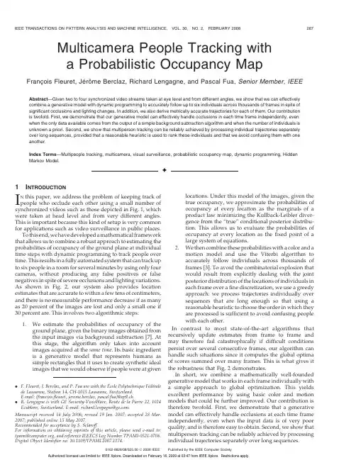
Multicamera People Tracking witha Probabilistic Occupancy MapFranc¸ois Fleuret,Je´roˆme Berclaz,Richard Lengagne,and Pascal Fua,Senior Member,IEEE Abstract—Given two to four synchronized video streams taken at eye level and from different angles,we show that we can effectively combine a generative model with dynamic programming to accurately follow up to six individuals across thousands of frames in spite of significant occlusions and lighting changes.In addition,we also derive metrically accurate trajectories for each of them.Our contribution is twofold.First,we demonstrate that our generative model can effectively handle occlusions in each time frame independently,even when the only data available comes from the output of a simple background subtraction algorithm and when the number of individuals is unknown a priori.Second,we show that multiperson tracking can be reliably achieved by processing individual trajectories separately over long sequences,provided that a reasonable heuristic is used to rank these individuals and that we avoid confusing them with one another.Index Terms—Multipeople tracking,multicamera,visual surveillance,probabilistic occupancy map,dynamic programming,Hidden Markov Model.Ç1I NTRODUCTIONI N this paper,we address the problem of keeping track of people who occlude each other using a small number of synchronized videos such as those depicted in Fig.1,which were taken at head level and from very different angles. This is important because this kind of setup is very common for applications such as video surveillance in public places.To this end,we have developed a mathematical framework that allows us to combine a robust approach to estimating the probabilities of occupancy of the ground plane at individual time steps with dynamic programming to track people over time.This results in a fully automated system that can track up to six people in a room for several minutes by using only four cameras,without producing any false positives or false negatives in spite of severe occlusions and lighting variations. As shown in Fig.2,our system also provides location estimates that are accurate to within a few tens of centimeters, and there is no measurable performance decrease if as many as20percent of the images are lost and only a small one if 30percent are.This involves two algorithmic steps:1.We estimate the probabilities of occupancy of theground plane,given the binary images obtained fromthe input images via background subtraction[7].Atthis stage,the algorithm only takes into accountimages acquired at the same time.Its basic ingredientis a generative model that represents humans assimple rectangles that it uses to create synthetic idealimages that we would observe if people were at givenlocations.Under this model of the images,given thetrue occupancy,we approximate the probabilities ofoccupancy at every location as the marginals of aproduct law minimizing the Kullback-Leibler diver-gence from the“true”conditional posterior distribu-tion.This allows us to evaluate the probabilities ofoccupancy at every location as the fixed point of alarge system of equations.2.We then combine these probabilities with a color and amotion model and use the Viterbi algorithm toaccurately follow individuals across thousands offrames[3].To avoid the combinatorial explosion thatwould result from explicitly dealing with the jointposterior distribution of the locations of individuals ineach frame over a fine discretization,we use a greedyapproach:we process trajectories individually oversequences that are long enough so that using areasonable heuristic to choose the order in which theyare processed is sufficient to avoid confusing peoplewith each other.In contrast to most state-of-the-art algorithms that recursively update estimates from frame to frame and may therefore fail catastrophically if difficult conditions persist over several consecutive frames,our algorithm can handle such situations since it computes the global optima of scores summed over many frames.This is what gives it the robustness that Fig.2demonstrates.In short,we combine a mathematically well-founded generative model that works in each frame individually with a simple approach to global optimization.This yields excellent performance by using basic color and motion models that could be further improved.Our contribution is therefore twofold.First,we demonstrate that a generative model can effectively handle occlusions at each time frame independently,even when the input data is of very poor quality,and is therefore easy to obtain.Second,we show that multiperson tracking can be reliably achieved by processing individual trajectories separately over long sequences.. F.Fleuret,J.Berclaz,and P.Fua are with the Ecole Polytechnique Fe´de´ralede Lausanne,Station14,CH-1015Lausanne,Switzerland.E-mail:{francois.fleuret,jerome.berclaz,pascal.fua}@epfl.ch..R.Lengagne is with GE Security-VisioWave,Route de la Pierre22,1024Ecublens,Switzerland.E-mail:richard.lengagne@.Manuscript received14July2006;revised19Jan.2007;accepted28Mar.2007;published online15May2007.Recommended for acceptance by S.Sclaroff.For information on obtaining reprints of this article,please send e-mail to:tpami@,and reference IEEECS Log Number TPAMI-0521-0706.Digital Object Identifier no.10.1109/TPAMI.2007.1174.0162-8828/08/$25.00ß2008IEEE Published by the IEEE Computer SocietyIn the remainder of the paper,we first briefly review related works.We then formulate our problem as estimat-ing the most probable state of a hidden Markov process and propose a model of the visible signal based on an estimate of an occupancy map in every time frame.Finally,we present our results on several long sequences.2R ELATED W ORKState-of-the-art methods can be divided into monocular and multiview approaches that we briefly review in this section.2.1Monocular ApproachesMonocular approaches rely on the input of a single camera to perform tracking.These methods provide a simple and easy-to-deploy setup but must compensate for the lack of 3D information in a single camera view.2.1.1Blob-Based MethodsMany algorithms rely on binary blobs extracted from single video[10],[5],[11].They combine shape analysis and tracking to locate people and maintain appearance models in order to track them,even in the presence of occlusions.The Bayesian Multiple-BLob tracker(BraMBLe)system[12],for example,is a multiblob tracker that generates a blob-likelihood based on a known background model and appearance models of the tracked people.It then uses a particle filter to implement the tracking for an unknown number of people.Approaches that track in a single view prior to computing correspondences across views extend this approach to multi camera setups.However,we view them as falling into the same category because they do not simultaneously exploit the information from multiple views.In[15],the limits of the field of view of each camera are computed in every other camera from motion information.When a person becomes visible in one camera,the system automatically searches for him in other views where he should be visible.In[4],a background/foreground segmentation is performed on calibrated images,followed by human shape extraction from foreground objects and feature point selection extraction. Feature points are tracked in a single view,and the system switches to another view when the current camera no longer has a good view of the person.2.1.2Color-Based MethodsTracking performance can be significantly increased by taking color into account.As shown in[6],the mean-shift pursuit technique based on a dissimilarity measure of color distributions can accurately track deformable objects in real time and in a monocular context.In[16],the images are segmented pixelwise into different classes,thus modeling people by continuously updated Gaussian mixtures.A standard tracking process is then performed using a Bayesian framework,which helps keep track of people,even when there are occlusions.In such a case,models of persons in front keep being updated, whereas the system stops updating occluded ones,which may cause trouble if their appearances have changed noticeably when they re-emerge.More recently,multiple humans have been simulta-neously detected and tracked in crowded scenes[20]by using Monte-Carlo-based methods to estimate their number and positions.In[23],multiple people are also detected and tracked in front of complex backgrounds by using mixture particle filters guided by people models learned by boosting.In[9],multicue3D object tracking is addressed by combining particle-filter-based Bayesian tracking and detection using learned spatiotemporal shapes.This ap-proach leads to impressive results but requires shape, texture,and image depth information as input.Finally, Smith et al.[25]propose a particle-filtering scheme that relies on Markov chain Monte Carlo(MCMC)optimization to handle entrances and departures.It also introduces a finer modeling of interactions between individuals as a product of pairwise potentials.2.2Multiview ApproachesDespite the effectiveness of such methods,the use of multiple cameras soon becomes necessary when one wishes to accurately detect and track multiple people and compute their precise3D locations in a complex environment. Occlusion handling is facilitated by using two sets of stereo color cameras[14].However,in most approaches that only take a set of2D views as input,occlusion is mainly handled by imposing temporal consistency in terms of a motion model,be it Kalman filtering or more general Markov models.As a result,these approaches may not always be able to recover if the process starts diverging.2.2.1Blob-Based MethodsIn[19],Kalman filtering is applied on3D points obtained by fusing in a least squares sense the image-to-world projections of points belonging to binary blobs.Similarly,in[1],a Kalman filter is used to simultaneously track in2D and3D,and objectFig.1.Images from two indoor and two outdoor multicamera video sequences that we use for our experiments.At each time step,we draw a box around people that we detect and assign to them an ID number that follows them throughout thesequence.Fig.2.Cumulative distributions of the position estimate error on a3,800-frame sequence(see Section6.4.1for details).locations are estimated through trajectory prediction during occlusion.In[8],a best hypothesis and a multiple-hypotheses approaches are compared to find people tracks from 3D locations obtained from foreground binary blobs ex-tracted from multiple calibrated views.In[21],a recursive Bayesian estimation approach is used to deal with occlusions while tracking multiple people in multiview.The algorithm tracks objects located in the intersections of2D visual angles,which are extracted from silhouettes obtained from different fixed views.When occlusion ambiguities occur,multiple occlusion hypotheses are generated,given predicted object states and previous hypotheses,and tested using a branch-and-merge strategy. The proposed framework is implemented using a customized particle filter to represent the distribution of object states.Recently,Morariu and Camps[17]proposed a method based on dimensionality reduction to learn a correspondence between the appearance of pedestrians across several views. This approach is able to cope with the severe occlusion in one view by exploiting the appearance of the same pedestrian on another view and the consistence across views.2.2.2Color-Based MethodsMittal and Davis[18]propose a system that segments,detects, and tracks multiple people in a scene by using a wide-baseline setup of up to16synchronized cameras.Intensity informa-tion is directly used to perform single-view pixel classifica-tion and match similarly labeled regions across views to derive3D people locations.Occlusion analysis is performed in two ways:First,during pixel classification,the computa-tion of prior probabilities takes occlusion into account. Second,evidence is gathered across cameras to compute a presence likelihood map on the ground plane that accounts for the visibility of each ground plane point in each view. Ground plane locations are then tracked over time by using a Kalman filter.In[13],individuals are tracked both in image planes and top view.The2D and3D positions of each individual are computed so as to maximize a joint probability defined as the product of a color-based appearance model and2D and 3D motion models derived from a Kalman filter.2.2.3Occupancy Map MethodsRecent techniques explicitly use a discretized occupancy map into which the objects detected in the camera images are back-projected.In[2],the authors rely on a standard detection of stereo disparities,which increase counters associated to square areas on the ground.A mixture of Gaussians is fitted to the resulting score map to estimate the likely location of individuals.This estimate is combined with a Kallman filter to model the motion.In[26],the occupancy map is computed with a standard visual hull procedure.One originality of the approach is to keep for each resulting connex component an upper and lower bound on the number of objects that it can contain. Based on motion consistency,the bounds on the various components are estimated at a certain time frame based on the bounds of the components at the previous time frame that spatially intersect with it.Although our own method shares many features with these techniques,it differs in two important respects that we will highlight:First,we combine the usual color and motion models with a sophisticated approach based on a generative model to estimating the probabilities of occu-pancy,which explicitly handles complex occlusion interac-tions between detected individuals,as will be discussed in Section5.Second,we rely on dynamic programming to ensure greater stability in challenging situations by simul-taneously handling multiple frames.3P ROBLEM F ORMULATIONOur goal is to track an a priori unknown number of people from a few synchronized video streams taken at head level. In this section,we formulate this problem as one of finding the most probable state of a hidden Markov process,given the set of images acquired at each time step,which we will refer to as a temporal frame.We then briefly outline the computation of the relevant probabilities by using the notations summarized in Tables1and2,which we also use in the following two sections to discuss in more details the actual computation of those probabilities.3.1Computing the Optimal TrajectoriesWe process the video sequences by batches of T¼100frames, each of which includes C images,and we compute the most likely trajectory for each individual.To achieve consistency over successive batches,we only keep the result on the first 10frames and slide our temporal window.This is illustrated in Fig.3.We discretize the visible part of the ground plane into a finite number G of regularly spaced2D locations and we introduce a virtual hidden location H that will be used to model entrances and departures from and into the visible area.For a given batch,let L t¼ðL1t;...;L NÃtÞbe the hidden stochastic processes standing for the locations of individuals, whether visible or not.The number NÃstands for the maximum allowable number of individuals in our world.It is large enough so that conditioning on the number of visible ones does not change the probability of a new individual entering the scene.The L n t variables therefore take values in f1;...;G;Hg.Given I t¼ðI1t;...;I C tÞ,the images acquired at time t for 1t T,our task is to find the values of L1;...;L T that maximizePðL1;...;L T j I1;...;I TÞ:ð1ÞAs will be discussed in Section 4.1,we compute this maximum a posteriori in a greedy way,processing one individual at a time,including the hidden ones who can move into the visible scene or not.For each one,the algorithm performs the computation,under the constraint that no individual can be at a visible location occupied by an individual already processed.In theory,this approach could lead to undesirable local minima,for example,by connecting the trajectories of two separate people.However,this does not happen often because our batches are sufficiently long.To further reduce the chances of this,we process individual trajectories in an order that depends on a reliability score so that the most reliable ones are computed first,thereby reducing the potential for confusion when processing the remaining ones. This order also ensures that if an individual remains in the hidden location,then all the other people present in the hidden location will also stay there and,therefore,do not need to be processed.FLEURET ET AL.:MULTICAMERA PEOPLE TRACKING WITH A PROBABILISTIC OCCUPANCY MAP269Our experimental results show that our method does not suffer from the usual weaknesses of greedy algorithms such as a tendency to get caught in bad local minima.We thereforebelieve that it compares very favorably to stochastic optimization techniques in general and more specifically particle filtering,which usually requires careful tuning of metaparameters.3.2Stochastic ModelingWe will show in Section 4.2that since we process individual trajectories,the whole approach only requires us to define avalid motion model P ðL n t þ1j L nt ¼k Þand a sound appearance model P ðI t j L n t ¼k Þ.The motion model P ðL n t þ1j L nt ¼k Þ,which will be intro-duced in Section 4.3,is a distribution into a disc of limited radiusandcenter k ,whichcorresponds toalooseboundonthe maximum speed of a walking human.Entrance into the scene and departure from it are naturally modeled,thanks to the270IEEE TRANSACTIONS ON PATTERN ANALYSIS AND MACHINE INTELLIGENCE,VOL.30,NO.2,FEBRUARY 2008TABLE 2Notations (RandomQuantities)Fig.3.Video sequences are processed by batch of 100frames.Only the first 10percent of the optimization result is kept and the rest is discarded.The temporal window is then slid forward and the optimiza-tion is repeated on the new window.TABLE 1Notations (DeterministicQuantities)hiddenlocation H,forwhichweextendthemotionmodel.The probabilities to enter and to leave are similar to the transition probabilities between different ground plane locations.In Section4.4,we will show that the appearance model PðI t j L n t¼kÞcan be decomposed into two terms.The first, described in Section4.5,is a very generic color-histogram-based model for each individual.The second,described in Section5,approximates the marginal conditional probabil-ities of occupancy of the ground plane,given the results of a background subtractionalgorithm,in allviewsacquired atthe same time.This approximation is obtained by minimizing the Kullback-Leibler divergence between a product law and the true posterior.We show that this is equivalent to computing the marginal probabilities of occupancy so that under the product law,the images obtained by putting rectangles of human sizes at occupied locations are likely to be similar to the images actually produced by the background subtraction.This represents a departure from more classical ap-proaches to estimating probabilities of occupancy that rely on computing a visual hull[26].Such approaches tend to be pessimistic and do not exploit trade-offs between the presence of people at different locations.For instance,if due to noise in one camera,a person is not seen in a particular view,then he would be discarded,even if he were seen in all others.By contrast,in our probabilistic framework,sufficient evidence might be present to detect him.Similarly,the presence of someone at a specific location creates an occlusion that hides the presence behind,which is not accounted for by the hull techniques but is by our approach.Since these marginal probabilities are computed indepen-dently at each time step,they say nothing about identity or correspondence with past frames.The appearance similarity is entirely conveyed by the color histograms,which has experimentally proved sufficient for our purposes.4C OMPUTATION OF THE T RAJECTORIESIn Section4.1,we break the global optimization of several people’s trajectories into the estimation of optimal individual trajectories.In Section 4.2,we show how this can be performed using the classical Viterbi’s algorithm based on dynamic programming.This requires a motion model given in Section 4.3and an appearance model described in Section4.4,which combines a color model given in Section4.5 and a sophisticated estimation of the ground plane occu-pancy detailed in Section5.We partition the visible area into a regular grid of G locations,as shown in Figs.5c and6,and from the camera calibration,we define for each camera c a family of rectangular shapes A c1;...;A c G,which correspond to crude human silhouettes of height175cm and width50cm located at every position on the grid.4.1Multiple TrajectoriesRecall that we denote by L n¼ðL n1;...;L n TÞthe trajectory of individual n.Given a batch of T temporal frames I¼ðI1;...;I TÞ,we want to maximize the posterior conditional probability:PðL1¼l1;...;L Nül NÃj IÞ¼PðL1¼l1j IÞY NÃn¼2P L n¼l n j I;L1¼l1;...;L nÀ1¼l nÀ1ÀÁ:ð2ÞSimultaneous optimization of all the L i s would beintractable.Instead,we optimize one trajectory after theother,which amounts to looking for^l1¼arg maxlPðL1¼l j IÞ;ð3Þ^l2¼arg maxlPðL2¼l j I;L1¼^l1Þ;ð4Þ...^l Nüarg maxlPðL Nül j I;L1¼^l1;L2¼^l2;...Þ:ð5ÞNote that under our model,conditioning one trajectory,given other ones,simply means that it will go through noalready occupied location.In other words,PðL n¼l j I;L1¼^l1;...;L nÀ1¼^l nÀ1Þ¼PðL n¼l j I;8k<n;8t;L n t¼^l k tÞ;ð6Þwhich is PðL n¼l j IÞwith a reduced set of the admissiblegrid locations.Such a procedure is recursively correct:If all trajectoriesestimated up to step n are correct,then the conditioning onlyimproves the estimate of the optimal remaining trajectories.This would suffice if the image data were informative enoughso that locations could be unambiguously associated toindividuals.In practice,this is obviously rarely the case.Therefore,this greedy approach to optimization has un-desired side effects.For example,due to partly missinglocalization information for a given trajectory,the algorithmmight mistakenly start following another person’s trajectory.This is especially likely to happen if the tracked individualsare located close to each other.To avoid this kind of failure,we process the images bybatches of T¼100and first extend the trajectories that havebeen found with high confidence,as defined below,in theprevious batches.We then process the lower confidenceones.As a result,a trajectory that was problematic in thepast and is likely to be problematic in the current batch willbe optimized last and,thus,prevented from“stealing”somebody else’s location.Furthermore,this approachincreases the spatial constraints on such a trajectory whenwe finally get around to estimating it.We use as a confidence score the concordance of theestimated trajectories in the previous batches and thelocalization cue provided by the estimation of the probabil-istic occupancy map(POM)described in Section5.Moreprecisely,the score is the number of time frames where theestimated trajectory passes through a local maximum of theestimated probability of occupancy.When the POM does notdetect a person on a few frames,the score will naturallydecrease,indicating a deterioration of the localizationinformation.Since there is a high degree of overlappingbetween successive batches,the challenging segment of atrajectory,which is due to the failure of the backgroundsubtraction or change in illumination,for instance,is met inseveral batches before it actually happens during the10keptframes.Thus,the heuristic would have ranked the corre-sponding individual in the last ones to be processed whensuch problem occurs.FLEURET ET AL.:MULTICAMERA PEOPLE TRACKING WITH A PROBABILISTIC OCCUPANCY MAP2714.2Single TrajectoryLet us now consider only the trajectory L n ¼ðL n 1;...;L nT Þof individual n over T temporal frames.We are looking for thevalues ðl n 1;...;l nT Þin the subset of free locations of f 1;...;G;Hg .The initial location l n 1is either a known visible location if the individual is visible in the first frame of the batch or H if he is not.We therefore seek to maximizeP ðL n 1¼l n 1;...;L n T ¼l nt j I 1;...;I T Þ¼P ðI 1;L n 1¼l n 1;...;I T ;L n T ¼l nT ÞP ðI 1;...;I T Þ:ð7ÞSince the denominator is constant with respect to l n ,we simply maximize the numerator,that is,the probability of both the trajectories and the images.Let us introduce the maximum of the probability of both the observations and the trajectory ending up at location k at time t :Èt ðk Þ¼max l n 1;...;l nt À1P ðI 1;L n 1¼l n 1;...;I t ;L nt ¼k Þ:ð8ÞWe model jointly the processes L n t and I t with a hidden Markov model,that isP ðL n t þ1j L n t ;L n t À1;...Þ¼P ðL n t þ1j L nt Þð9ÞandP ðI t ;I t À1;...j L n t ;L nt À1;...Þ¼YtP ðI t j L n t Þ:ð10ÞUnder such a model,we have the classical recursive expressionÈt ðk Þ¼P ðI t j L n t ¼k Þ|fflfflfflfflfflfflfflfflffl{zfflfflfflfflfflfflfflfflffl}Appearance modelmax P ðL n t ¼k j L nt À1¼ Þ|fflfflfflfflfflfflfflfflfflfflfflfflfflfflfflfflffl{zfflfflfflfflfflfflfflfflfflfflfflfflfflfflfflfflffl}Motion modelÈt À1ð Þð11Þto perform a global search with dynamic programming,which yields the classic Viterbi algorithm.This is straight-forward,since the L n t s are in a finite set of cardinality G þ1.4.3Motion ModelWe chose a very simple and unconstrained motion model:P ðL n t ¼k j L nt À1¼ Þ¼1=Z Áe À k k À k if k k À k c 0otherwise ;&ð12Þwhere the constant tunes the average human walkingspeed,and c limits the maximum allowable speed.This probability is isotropic,decreases with the distance from location k ,and is zero for k k À k greater than a constantmaximum distance.We use a very loose maximum distance cof one square of the grid per frame,which corresponds to a speed of almost 12mph.We also define explicitly the probabilities of transitions to the parts of the scene that are connected to the hidden location H .This is a single door in the indoor sequences and all the contours of the visible area in the outdoor sequences in Fig.1.Thus,entrance and departure of individuals are taken care of naturally by the estimation of the maximum a posteriori trajectories.If there are enough evidence from the images that somebody enters or leaves the room,then this procedure will estimate that the optimal trajectory does so,and a person will be added to or removed from the visible area.4.4Appearance ModelFrom the input images I t ,we use background subtraction to produce binary masks B t such as those in Fig.4.We denote as T t the colors of the pixels inside the blobs and treat the rest of the images as background,which is ignored.Let X tk be a Boolean random variable standing for the presence of an individual at location k of the grid at time t .In Appendix B,we show thatP ðI t j L n t ¼k Þzfflfflfflfflfflfflfflfflffl}|fflfflfflfflfflfflfflfflffl{Appearance model/P ðL n t ¼k j X kt ¼1;T t Þ|fflfflfflfflfflfflfflfflfflfflfflfflfflfflfflfflfflffl{zfflfflfflfflfflfflfflfflfflfflfflfflfflfflfflfflfflffl}Color modelP ðX kt ¼1j B t Þ|fflfflfflfflfflfflfflfflfflfflffl{zfflfflfflfflfflfflfflfflfflfflffl}Ground plane occupancy:ð13ÞThe ground plane occupancy term will be discussed in Section 5,and the color model term is computed as follows.4.5Color ModelWe assume that if someone is present at a certain location k ,then his presence influences the color of the pixels located at the intersection of the moving blobs and the rectangle A c k corresponding to the location k .We model that dependency as if the pixels were independent and identically distributed and followed a density in the red,green,and blue (RGB)space associated to the individual.This is far simpler than the color models used in either [18]or [13],which split the body area in several subparts with dedicated color distributions,but has proved sufficient in practice.If an individual n was present in the frames preceding the current batch,then we have an estimation for any camera c of his color distribution c n ,since we have previously collected the pixels in all frames at the locations272IEEE TRANSACTIONS ON PATTERN ANALYSIS AND MACHINE INTELLIGENCE,VOL.30,NO.2,FEBRUARY2008Fig.4.The color model relies on a stochastic modeling of the color of the pixels T c t ðk Þsampled in the intersection of the binary image B c t produced bythe background subtraction and the rectangle A ck corresponding to the location k .。
Lens not includedPanasonic WV-S1131 captures the highest quality images automatically even in very challenging and fast-changingsurveillance environments. Intelligent Auto (iA) allows the camera to automatically adjust the key settings in real-time depending on the scenery and movement, reducing distortion such as motion blur and moving objects. New industry-leading 144dB dynamic range delivers balanced scene exposure in dynamic and extreme-backlit lighting environments. In addition, color night vision provides outstanding low-light performance with accurate color rendition and saturation from i-Pro's 1/3" sensor, rivaling the performance of costlier 1/2" sensor cameras in the market. The adopted H.265 Smart Coding technology, intelligently reduces bandwidth efficiency of up to 95%* more than H.264 for longer recording and less storage. Cameras out-of-the-box, support full data encryption streaming and is compliant to FIPS 140-2 Level 1 standards to keep your video secured.*Value in Advanced mode with Smart Facial Coding. It depends on the scene.Extreme image quality allows evidence to be captured even under challenging conditions-Auto Shutter speed control for fast moving vehicles -Sharp and clear images of a walking person day & night-Outstanding low light performance in true color with low noise for night time applications-Super Dynamic 144dB for backlit situations involving headlights and shadows on night streetsExtreme H.265 compression with new Smart Coding-Longer recording and less storage compared to any H.264 based compression techniques-New self-learning ROI* encoding (Auto VIQS) detects movement within the image and compresses the areas with little motion in order to reduce transmitted data while maintaining the quality of the image.-New “Smart Facial Coding” adds more bandwidth reduction for ID camera applications mainly capturing faces*Region of InterestExtreme Data Security-Full encryption SD card edge recording to keep your data safe -FIPS 140-2 Level 1 compliant-Full end-to-end system encryption with supported VMS and devices to protect from IP snooping/spoofing and detect data alterationiA (intelligent Auto) H.265 Network Camera•Full HD 1080p 60fps •iA (intelligent Auto)•Extreme Super Dynamic 144dB •Color night vision (0.0007 to 0.01 lx)•H.265 Smart Coding•FIPS 140-2 Level 1 compliantKey Features•Public safety (City / Road / Highway / Port)•Transportation (Airport / Train / Subway)•Retail / Bank / Education / Hospital / BuildingApplicationsWV-S1131PJ(Made in JAPAN)DISTRIBUTED BY :https:///PanasonicNetworkCamera(2A-170DA)Trademarks and registered trademarks– iPad and iPhone are registered trademarks of Apple Inc.– Android is a trademark of Google Inc.– ONVIF and the ONVIF logo are trademarks or registered trademarks of ONVIF Inc.– All other trademarks identified herein are the property of their respective owners.• Masses and dimensions are approximate. • Specifications are subject to change without notice.Important– Safety Precaution : Carefully read the Important Information, Installation Guide and operating instructions before using this product.– Panasonic cannot be responsible for the performance of the network and/or other manufacturers' products used on the network.Specifications*2 Super Dynamic function is automatically set off on 60 fps mode.*3 Stabilizer, Smart Facial Coding, i-VMD can not be used at the same time.*4 When “3 mega pixel [4 : 3](30fps mode)” is selected for “Image capture mode”, “90 °” and “270 °” cannot be selected.*5 Used by super resolution techniques*6 Transmission for 4 streams can be individually set.*7 Only use AAC-LC (Advanced Audio Coding - Low Complexity) when recording audio on an SD memory card.*8 Including alarms from Plug-in SoftwareAppearanceOptional AccessoryUnit : mm (inches)Notification sent to the monitoring screen。
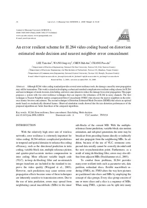
Lee et al./J Z hejiang Univ SCIENCE A 20067(Suppl.I):34-4034An error resilient scheme for H.264video coding based on distortion estimated mode decision and nearest neighbor error concealmentLEE Tien-hsu 1,WANG Jong-tzy 2,CHEN Jhih-bin 3,CHANG Pao-chi 3(1Departm ent of Electrical Engineering,National Chi Nan University,T aiwan 545,Puli,Nantou County)(2Departm ent of Electronic Engineering,J in-W en Ins titute of Technology,T aiwan 231,Shindian,Taipei County)(3Department of Com munication Engineering,National Central University,T aiwan 320,Jhongli,T aoyuan County )E -mail:thlee@.tw;jtwang@.tw;jbchen@.tw;pcchang@.twReceived Dec.2,2005;revision accepted Feb.19,2006Abstract:Although H.264video coding standard provides several error resilience tools,the damage caused by error propagationmay still be tremendous.This work is aimed at developing a robust and standard-compliant error resilient coding scheme for H.264and uses techniques of mode decision,data hiding,and error concealment to reduce the damage from error propagation.This paper proposes a system with two error resilience techniques that can improve the robustness of H.264in noisy channels.The first technique is Nearest Neighbor motion compensated Error Concealment (NNEC)that chooses the nearest neighbors in the refer-ence frames for error concealment.The second technique is Distortion Estimated Mode Decision (DEMD)that selects an optimal mode based on stochastically distorted frames.Observed simulation results showed that the rate-distortion performances of the proposed algorithms are better than those of the compared algorithms.Key words:H.264,Error resilience,Error concealment,Data hiding,Mode decision doi:10.1631/jzus.2006.AS0034Document code:A CLC number:TN919.8INTRODUCTIONWith the relatively high error rate of wireless networks,error resilience is extremely important for video coding.H.264utilizes complicated predictions in temporal and spatial domains to enhance the coding efficiency,such as the directional prediction in intra coding,variable block size,multiple reference picture,and quarter-pixel-accurate motion compensation in inter coding.More efficient variable length code (VLC),in-loop de-blocking filter and no-mismatch integer transform are included in the standard to im-prove the video quality (Wiegand et al.,2003).However,such predictions may cause serious error propagation effects because some of these techniques are inherently sensitive to transmission errors.Due to the use of intra prediction,errors may spread from neighboring causal macroblocks (MBs)to the inner sub-blocks of the current MB.With the multiple-reference-frame prediction,variable-block-size motion estimation,and sub-pixel generation,the error may be broadcast from preceding frames directly or indirectly and also propagate from the neighboring MBs.In ad-dition,because of the use of VLC,erroneous com-pressed data usually cannot be correctly decoded until the next resynchronization point.Furthermore,as a result of using de-blocking filter,errors may also dif-fuse from adjacent MBs (Stockhammer et a l.,2003).To combat these problems,H.264provides many error resilient tools such as parameter sets,data partition,redundant slices,flexible macroblock or-dering (FMO),etc.FMO alters the way how pictures are partitioned into slices and MBs by employing the concept of slice groups.Every slice group consists of one or more slices and a slice is a sequence of MBs.When using FMO,a picture can be split into manyJ ournal of Z hejiang University SCIENCE A ISSN 1009-3095(Print);ISSN 1862-1775(Online)/jzus; E-mail:jzus@L ee et al./J Z hejiang Univ SCIE NCE A20067(Suppl.I):34-4035MB scanning patterns such as interleaved slices. Redundant Slice(RS)allows the encoder to place,in addition to the coded MBs of the slice itself,one or more redundant representations of the same MBs into the same bit stream.RS is useful in that the redundant representation can be coded using different coding parameters,such as QP or reference frame index.The parameter set contains information that is expected to rarely change and enable decoding of a large number of VCL NAL units(Wenger,2003).Unfortunately,the error propagation effect still cannot be entirely eliminated by using the above tools. More research works on error resilience are still in progress.The error resilient encoding approach selects intra coded MBs in random or certain update pattern.A typical work(Wiegand and Girod,2001)considers the use of Lagrangian optimized mode decision when assigning intra MBs with significant improvements in the rate-distortion performance.A rate-distortion op-timization approach for H.26L video coding in packet loss environment is analytically investigated by Stockhammer et a l.(2002).By averaging over several decoders with different channel statistics,the expected MB distortions of decoders are calculated at the en-coder and the optimized mode is selected accordingly. An error resilient coding scheme based on data em-bedding is proposed by Kang and Leou(2005),in which a relatively large volume of important data useful for error concealment are embedded before-hand into video frames at the encoder.The conceal-ment result is satisfactory but15error concealment schemes for an MB must be pre-evaluated at the en-coder.Even so,the error propagation effect still exists.Our goal is to develop a robust and standard-compliant error resilient coding scheme for H.264 without a feedback channel.It utilizes techniques of mode decision,data hiding,and error concealment to reduce the damage from error propagation.This paper is organized as follows.The details of the two pro-posed algorithms,Nearest Neighbor motion com-pensated Error Concealment(NNEC)and Distortion Estimated Mode Decision(DEMD),are described in the next two sections,respectively.Simulation results and comparisons of the proposed algorithms are given in Section4,and at last,this research work is con-cluded in Section5.NEAREST NEIGHBOR ERROR CONCEALMENT (NNEC)The first technique is Nearest Neighbor Error Concealment(NNEC)that performs motion com-pensated error concealment with a better estimation of motion information.It utilizes a data hiding tech-nique to embed the index code of important informa-tion about the most similar neighboring block into the bit stream,presumably the next slice.The hiding information includes the coding mode of current MB, and its corresponding nearest neighboring8×8blocks with the most similar motion vectors and reference frames.The determination of the nearest neighbors for each MB is shown in Fig.1.To simplify the compu-tation,only the modes with block size larger than or equal to8×8are considered.Depending on the mode of an MB,the number of motion vectors and the number of candidates for each MB are different.For instance,a16×16mode has a set of motion vectors chosen from8neighbors that can be represented by3 bits,while a16×8mode has two sets of motion vec-tors chosen from4neighbors each of which can be represented by2bits.The detailed bit assignment of the nearest neighbor that utilizes the principle of Huffman coding is shown in Fig.2.No more than7 bits are needed to represent the nearest neighbors for each MB in terms of the coding mode and motion information.45021367F ig.1Near est neighbor deter mination for eachMB(shaded area)Coding mode MV&Ref T otal bitsSkip2(00)0216×162(01)3(xxx)516×83(100)4(xx xx)78×163(101)4(xx xx)78×83(110)4(x x x x)7Other3(111)03(x)represents the embedded bit,x is0or1Fig.2Huffman coding of NNEC informationLee et al./J Z hejiang Univ SCIENCE A 20067(Suppl.I):34-4036The next problem is how to deliver the NNEC information to the receiving end.In this work,a data hiding method is used.We embed each code bit into one quantized residual DCT coefficient by adjusting the coefficient check sum in a 4×4DCT block (Chang et a l.,2001)to satisfy the rule in Eq.(1).150150121,2.ii ii Embeded bit LEVELM Embeded bit LEVELM ====+==∑∑(1)LEVEL i is the quantized value of the ith coeffi-cient and M is an arbitrary integer.By forcing the checksum to be 0or 1,one bit information can be embedded and extracted successfully.Once the decoder does not receive the correct MB data including its motion vectors,it can use the nearest neighboring blocks with the index codes ex-tracted from the bit steam to perform much more accurate error concealment than the conventional error concealment,like the one used in JM 9.4.By comparing the maximum amount of required hiding bits per MB,NNEC is only 7bits while that in (Kang and Leou,2005)is 48bits.Obviously,the NNEC results in less degradation in the rate-distortion per-formance from data embedding,and requires rela-tively low implementation complexity as well.DISTORTION ESTIMATED MODE DECISION(DEMD)The second technique is Distortion Estimated Mode Decision (DEMD).The overall pixel distortion of the reconstruction frame at the decoding side in-cludes the quantization error,concealment error,and propagation error.In DEMD method,the encoder estimates the decoder distortion by calculating and storing expected pixel mean and variance values frame-by-frame for a given packet error rate.It is assumed that each slice will not be packetized into more than one packet,i.e.,each data slice can be decoded independently except by referring to previ-ous frames.The notations for the signals are listed as follows::i m O Original ith pixel in frame m;:i m D Reconstructed ith pixel in frame m at de-coder;:i m C Concealed ith pixel in frame m;:i m E Reconstructed ith pixel in frame m at en-coder;:p Packet loss probability;:i m d Expected distortion of ith pixel in frame m.The expected distortion can be expressed by Eq.(2):222{()}()2{}+{()}.i i i i i i i m mm m m m m d E O D O O E D E D ==(2)Furthermore,the NNEC technique described in the previous section can also be incorporated into this mode decision technique.Depending on the used error concealment,the concealed image can be ex-pressed as =,i jm mn C D i.e.,it is replaced by the jthpixel in the previous n frames,if NNEC can be suc-cessfully applied;or ,i k mm o C D = i.e.,the k th pixel in the previous o frames,if the NNEC embedded in-formation is unfortunately lost,then a conventional error concealment method is employed.Moreover,{}im E D and 2{()}i m E D are calculated differently inintra and inter coding as follows.Intr a codingA packet will not be lost with probability 1p,then =.ii m m D E Otherwise,a packet will be lost withprobability p,then the error concealment will beperformed and =.i im m D C Moreover,NNEC is per-formed with the probability 1p,i.e.,no packet loss in the data hiding slice,while conventional error con-cealment is performed with the probability p if the data hiding slice is lost.2{}(1){}(1)[(1){}{}](1)(1){}{},ii i m m m ii i m m m ij mm nkmo E D p E pE C p E p p E C pE Cp E p p E Dp E D =+=++=++ (3)2222222222{()}(1)(){()}(1)()[(1){()}{()}](1)()(1){()}{()}.i i i m m m i i m m i mi j m m n k mo E D p E pE C p E p p E C pE Cp E p p E D p E D =+=++=++ (4)L ee et al./J Z hejiang Univ SCIE NCE A 20067(Suppl.I):34-4037Inter codingThe motion compensation is performed in the inter-coding.Assume the jth pixel in the nth previous frame is used to predict the ith pixel in the current frame,the residue,i.e.,the prediction error,is=.i i jm mmn e E E If the decoding end correctly receivesthe residue,motion vector,and the reference frame number,then the reconstructed pixel can be obtainedby =+.i j im m n m D D e If the packet will be lost with prob-ability p,then the concealed pixel i m C will be used to replace this pixel.Therefore,{}i m E D and 2{()}i m E D can be derived as follows:2{}(1){}{}(1){}[(1){}{}](1){}(1){}{},i ji im mn m m ji i m nm m i mj i jmnm mn kmo E D p E D e pE C p E D e p p E C pE C p E D e p p E D p E D =++=+++=+++ (5)22222222{()}(1){()}{()}(1)[{()}2{}+()][(1){()}{()}](1){()2(1){}i ji i m m nm m j i j i m n m m n m i i m mj i jm n m mn E D p E D e pE C p E D e E D e p p E C pE C p E D p e E D =++=+++=+ 2222(1)()(1){()}{()}.(6)i j m mn km o p e p p E D p E D +++Mode decisionWith the above analysis,the expected distortion i m d can be calculated for a given p and then be used as the distortion in the H.264mode decision procedure.Since imd includes the quantization error,concealment error,and error propagation distortion,the mode de-cision procedure will choose an optimum mode that minimizes the distortion for a given p.The encoder and decoder structures of the pro-posed error resilient video coding system are shown in Figs.3and 4,respectively.The procedure at the encoding end is as follows:(1)Calculate the expected distortion based on {}i m E D and 2{()}i m E D in mode decision;(2)After mode decision,store the best mode,motion vector,and the reference frame number in-formation for skip mode,mode 16×16,mode 16×8,mode 8×16,and mode 8×8;(3)After a frame is encoded,compare the re-corded data with neighboring blocks.Determine the NNEC data for each block;(4)Encode the NNEC data on a slice and embed them into Huffman coded bit stream of another slice;(5)Assume each block is lost,perform corre-sponding error concealment,calculate i mC and ;i mC(6)Update {}i m E D and 2{()}i m E D for each frame.At the decoding end,the DEMD with NNEC procedure is listed as follows:(1)Decode a slice based on H.264if the slice is not lost,and extract the NNEC data.If lost,skip this slice,and record the slice position;(2)Perform error concealment starting from frame boundary to the center after a frame is decoded;(3)For lost blocks,if the NNEC data can be ex-tracted successfully,perform NNEC.If not,use the conventional error concealment.The estimates are integrated into a rate-distortion model for optimal switching between various intra and inter coding modes for each MB.The resulting performance is better than the conventional mode decision (without estimating the decoder distortion)provided that the packet error rate can be estimated or fed back by the channel.In addition,unlike the sta-tistical approach introduced in (Stockhammer et al.,2002),the DEMD requires relatively low implemen-tation complexity and is suitable for practical use.SIMULATION RESULTSWe assess the proposed error resilient scheme in environments with random packet loss rates of 5%and 20%.The illustrated test video sequence is QCIF Foreman and the FMO is enabled with two slice groups mapping as a checker-board type.One slice composed of 11MBs is packetized into one packet.We adopt the following abbreviations to represent the results with various techniques applied.(1)JM 9.4Error Free:error free.(2)NNEC Error Free:error free with hidden NNEC information codes.(3)JM 9.4EC:error concealment (EC)used in JM 9.4.(4)NNEC:nearest neighbor motion compen-Lee et al./J Z hejiang Univ SCIENCE A 20067(Suppl.I):34-4038sated EC.(5)DEMD:distortion estimated mode decision.(6)RIR:random intra refresh.By investigating the simulation results,the rate-distortion (R-D)performances of the proposed techniques are better than those of the compared al-gorithms in all experiments.For example,Fig.5shows that the proposed NNEC only degrades the PSNR by about 0.5dB in the error free case.However,NNEC can additionally enhance the error conceal-ment approach suggested in JM 9.4by more than 1.5dB in noisy environment.Obviously,the enhance-ment cannot be further increased especially in a high bit rate situation due to the inherent characteristics that error propagation effects cannot be avoided by simply applying error concealment.In contrast to Fig.6,the proposed DEMD technique can signifi-cantly further improve the video quality by more thanEntropyInve rse Inve rse Da ta Hidi ngR ec ord Codi ng Mode ,MV a nd Re fChoose the best mode that minimize RDCos tExpected decoder pixel distortionE mbed NNE C data into AC coefficientsNNEC dataNNEC concealmentMotionestimationFind NNB and map to NNECdataUpdate expected decoder pixelRecord coding mode,MV and Ref Expected decoderpixelTransformNALE ntropy codingData hiding INTRAMotion compensationInverse quantization QuantizationChannelEDM OINTERFrame storeDe-blockingInvers e trans formFig.3Encoder structure of the proposed error resilience systemNALChannelEntropy codingNNEC dataINTERINTRA Inverse quantization Inverse transformRes tore co ding mode,MV andRefNNEC data interpretationMotion compensationExtract NNEC data from coefficientsDe-blockingIf MB is lost then enable NNEC concealmentNNEC error concealmentFrame storeFig.4Decoder structure of the proposed error resilience systemIntra predictionL ee et al./J Z hejiang Univ SCIE NCE A 20067(Suppl.I):34-40394dB compared with the error concealment or random intra refresh approach especially at the high bit rate of 500kbps and packet loss rate of 20%.Of course,bycombining DEMD with NNEC,the proposed errorresilient scheme achieves the best rate-distortion performance as shown in Fig.7.(d B )(d B )(d B )(d B )(d B )(d B )2829303132333435100000200000300000400000500000Bit RateP S N R 25262728293031100000200000300000400000500000Bit RateP S N R(a)(b)Fig.6R-D comparison of DEMD and RIR at packet loss rates of (a)5%and (b)20%26272829303132100000200000300000400000500000Bit RateP S N R293031323334353637100000200000300000400000500000Bit RateP S N R (a)(b)Fig.7R-D com par ison of DEM D &NNEC a nd RI R &NNEC a t pa c k e t loss r a tes of (a )5%and (b)20%12345Bit rate (×105bps)12345Bit rate (×105bps)12345Bit rate (×105bps )12345Bit rate (×105bps)24262830323436384042100000200000300000400000500000Bit RateP S N R 2931333537394143100000200000300000400000500000Bit Rate P S N R (a)(b)Fig.5R -D com par ison of NNEC and J M 9.4er r or concealment a t pa cket loss r a tes of (a )5%and (b)20%NNECJM 9.4ECNNEC error free JM 9.4error fre e12345Bit rate (×105bps )12345Bit rate (×105bps)NNECJM 9.4ECNNEC error free JM 9.4error fre eDEMDRIRDEMDRIRDEMD &NNECRIR &NNECDEMD &NNECRIR &NN ECLee et al./J Z hejiang Univ SCIENCE A 20067(Suppl.I):34-4040CONCLUSIONThe proposed error-resilient NNEC and DEMD techniques are not mutually exclusive,i.e.,they can be applied together in a system without degrading each individual performance.The combined system performs better than the compared methods without requiring a feedback channel.ACKNOWLEDGEMENTThis work was supported in part by grants from the National Science Council of T aiwan under con-tracts NSC 94-2213-E-008-021and NSC 94-2219-E-260-006.ReferencesChang,P.C.,Wang ,T.H.,Lee,T.H.,2001.An Efficient DataEmbedding Algorithm for H.263Compatible Video Coding.Proc.Data Compression Conference,p.489.Kang,L.W.,Leou,J.J.,2005.An error resilient coding schemefor H.264/AVC video transmission based on data em-bedding.J.Visual Communication and Image Repre-sentation,16(1):93-114.[do i :doi:10.1016/j .j vcir.2004.04.003]Stockhammer,T.,Kontopodis, D.,Wiegand,T.,2002.Rate-Distortion Optimization for JVT/H.26L Video Cod-ing in Packet Loss Environment.Proc.Int.Packet Video Workshop.Pittsburgh,USA.Stockhammer,T.,Hannuksela,M.,Wiegand,T.,2003.H.264/AVC in wireless environments.IEEE Trans.Cir-cuits Syst.Video Technol.,13(7):657-673.[d oi:10.1109/T CS VT.2003.815167]Wenger,S.,2003.H.264/AVC over IP.IEEE Trans.CircuitSyst.Video Technol.,13(7):645-656.[d oi:10.1109/T CS VT.2003.814966]Wiegand,T.,Girod,B.,grangeMultiplier Selection in Hybrid Video Coder Control.Proc.IEEE International Conference on Image Processing,3:542-545.Wiegand,T.,Sullivan,G.J.,Bjontegaard,G.,Luthra,A.,2003.Overview of the H.264/AVC video coding standard.IEEE Trans.Circuits Syst.V ideo Technol.,13(7):560-576.[do i :10.1109/TCS VT.2003.815165]JZUS -A foc us es on “Applied P hys ics &Engine e ring ”We lcome Your Contributions to JZUS-AJourna l of Zhejiang Univ ersity SCIENCE A warmly and sincerely welcomes scientists all overthe world to contribute Reviews,Articles and Science Letters focused on Applied Physics &Engi-neer ing.Especially,Science Letters (34pages)would be published as soon as about 30days (Note:detailed research articles can still be published in the professional journals in the future after Science Letters is published by JZUS-A).SCIENCE AJournal of Zhejiang UniversityEditors-in-Chief:Pan Yun-heISSN 1009-3095(P rin t);ISS N 1862-1775(On lin e ),mo n th ly/jz us ;www.springe jzus@zju.e du.c n。

Performance Series IPPerformance Series IP Embedded NVR Kits 3 Megapixel Full HD IP Cameras and 4 channel embedded NVRIntroducing the new Performance Series IP embedded NVR kits from Honeywell. The kits feature 3 Megapixel Full HD IR-illuminated IP66-rated cameras, and an embedded NVR with a user-friendly set-up and configuration wizard that takes you to live video in minutes. You have a choice of a 1 or 2 TB embedded NVR (Field upgradeable up to 12TB* storage max) and 4 IP ball cameras OR 4 IP bullet cameras. These bundled kits offer the perfect economical and flexible solution for small to medium sized businesses.Fully-featured NVRs• High decoding capability for full HD viewing and recording.• View up to four channels simultaneously on your monitor.• All channels live view and play back at 1080p @ full frame rate and 3MP @ 20 frames per second.• Bidirectional audio communication for the NVR.Fully-featured Cameras• IR LEDs facilitate recording in dimly lit or nighttime scenes.• Waterproof (IP66) camera housings are perfect for outdoor installations.• C amera configurations to improve image quality and reduce image size, and to detect and respond to alarm events.• 1/3” 3MP sensor, no distortion of image in 16:9 display, 12.5% more pixel density than conventional 3MP 4:3 cameras• Easy to Use• The Quick wizard and PoE support of plug-and-play makes setup fast and easy.• P hysical installation within minutes with the help of comprehensive and easy-to-understand quick installation guides for the NVR and IP cameras.Convenient, Flexible Storage Options• Internal storage supports two HDDs up to 12 TB (6 TB each).*• S tore videos and snapshots to external storage, such as the client 's PC, over the Internet.• Store videos and snapshots to an external network storage server such as an FTP site.• Store videos and snapshots to a USB memory device.Dynamic, Accessible Monitoring• M onitor from anywhere using the mobile apps for Apple and Android smartphones, tabletcomputers, and laptops.Privacy Masking• Conceal up to 4 areas of a scene from viewing and recording.Safety Features• Configurable motion detection and camera tamper detection settings, including configurable alarm alerts, such as automatic emails (with attached video or snapshot) and automatic alerts (such as buzzers or flashing lights).• R emote configuration and firmware updating through Honeywell Viewer web client and theHoneywell Config tool. Password-protected access to the camera’s and NVR’s video and network setup.Market Opportunities• The flexible storage options of the Performance Series IP Embedded NVR plus thefully-featured IPIR cameras make this kit perfect for many security applications.Performance Series IP FeaturesImmediately Detect and Respond toEventsThe Performance Series IP NVR/Cameras can beconfigured to automatically detect and respondto events such as motion in the scene, alarminputs, a network failure and/or tampering.Automated responses include:• Sending a notification through email, FTP and/or HTTP.• Uploading still images at the time of the eventthrough email and/or FTP.• Recording a video clip of the event to the client’sPC or network-attached storage.• Enabling a visual or auditory notification (aflashing light, bell or siren).Performance Series IPNVR specifications* Actual bitrate is scene and motion dependent with H.264 stream.** Some development might be required in specific user cases to support some of these protocols in the field as naturally protocols will mature over time.Performance Series IP Camera specificationsPerformance Series IP DimensionsHED3PR3 Ball CameraBullet Camera85,4 мм113,6 мм52,6 ммHSFV-Performance-01-UK(0816)-DS-R © 2016 Honeywell International Inc.For additional information, please visit:/security/ukHoneywell Security GroupAston Fields RoadWhitehouse Industrial Estate RuncornCheshire WA7 3DL Tel************Performance Series IPOrderingNOTE: Honeywell reserves the right, without notification, to make changes in product design or specifications.HEN04122EBXHoneywell Embedded NVR EB = Ball camera Kit BB = Bullet camera Kit X = PAL Version NVR Channels 1 or 2 TB storage1080p。

Key Feature● Up to 4-ch IP camera inputs● H.265+/H.265/H.264+/H.264 video formats● Up to 1-ch@12 MP or 2-ch@8 MP or 4-ch@4 MP or 8-ch@1080p decoding capacity● Up to 40 Mbps incoming bandwidth● Adopt Hikvision Acusense technology to minimize manual effortand security costsSmart Function● All channels support Motion Detection 2.0● 1-ch facial recognition for video stream, or 2-ch facial recognition for face picture● Smart search for the selected area in the video, and smart playback to improve the playback efficiencyProfessional and Reliability● H.265+ compression effectively reduces the storage space by up to 75%● Adopt stream over TLS encryption technology which provides more secure stream transmission serviceHD Video Output● Provide simultaneous HDMI and VGA outputs ● HDMI video output at up to 4K resolutionStorage and Playback● Up to 1 SATA interface for HDD connection (up to 10 TB)● 4-ch synchronous playbackNetwork & Ethernet Access● 1 self-adaptive 10/100/1000 Mbps Ethernet interface ● Hik-Connect for easy network managementSpecificationIntelligent AnalyticsAI by Device Facial recognition, perimeter protection, motion detection 2.0AI by Camera Facial recognition, perimeter protection, throwing objects from building, motion detection2.0, ANPR, VCAFacial RecognitionFacial Detection and Analytics Face picture comparison, human face capture, face picture searchFace Picture Library Up to 16 face picture libraries, with up to 20,000 face pictures in total (each picture ≤ 4 MB, total capacity ≤ 1 GB)Facial Detection and Analytics Performance1-ch, 8 MP Face Picture Comparison2-ch Motion Detection 2.0By Device All channels, 4 MP (when enhanced SVC mode is enabled, up to 8 MP) video analysis for human and vehicle recognition to reduce false alarmBy Camera All channels Perimeter ProtectionBy Device 1-ch, 4 MP (HD network camera, H.264/H.265) video analysis for human and vehicle recognition to reduce false alarmBy Camera All channels Video and AudioIP Video Input4-ch Incoming Bandwidth40 Mbps Outgoing Bandwidth80 MbpsHDMI Output 1-ch, 4K (3840 × 2160)/30 Hz, 2K (2560 × 1440)/60 Hz, 1920 × 1080/60 Hz, 1600 × 1200/60 Hz, 1280 × 1024/60 Hz, 1280 × 720/60 Hz, 1024 × 768/60 HzVGA Output1-ch, 1920 × 1080/60 Hz, 1280 × 1024/60 Hz, 1280 × 720/60 HzVideo Output Mode HDMI1/VGA simultaneous outputCVBS Output N/AAudio Output1-ch, RCA (Linear, 1 KΩ)Two-Way Audio1-ch, RCA (2.0 Vp-p, 1 KΩ, using the audio input)DecodingDecoding Format H.265/H.265+/H.264+/H.264Recording Resolution12 MP/8 MP/6 MP/5 MP/4 MP/3 MP/1080p/UXGA/720p/VGA/4CIF/DCIF/2CIF/CIF/QCIF Synchronous Playback4-chDecoding Capability AI on: 1-ch@12 MP (30 fps)/1-ch@8 MP (30 fps)/3-ch@4 MP (30 fps)/6-ch@1080p (30 fps)AI off: 1-ch@12 MP (30 fps)/2-ch@8 MP (30 fps)/4-ch@4 MP (30 fps)/8-ch@1080p (30 fps)Stream Type Video, Video & AudioAudio Compression G.711ulaw/G.711alaw/G.722/G.726/AACNetworkRemote Connection128API ONVIF (profile S/G); SDK; ISAPICompatible Browser IE11, Chrome V57, Firefox V52, Safari V12, Edge V89, or above versionNetwork Protocol TCP/IP, DHCP, IPv4, IPv6, DNS, DDNS, NTP, RTSP, SADP, SMTP, SNMP, NFS, iSCSI, ISUP, UPnP™, HTTP, HTTPSNetwork Interface 1 RJ-45 10/100/1000 Mbps self-adaptive Ethernet interface Auxiliary InterfaceSATA 1 SATA interfaceCapacity Up to 10 TB capacity for each HDDUSB Interface Front panel: 1 × USB 2.0; Rear panel: 1 × USB 2.0Alarm In/Out N/AGeneralGUI Language English, Russian, Bulgarian, Hungarian, Greek, German, Italian, Czech, Slovak, French, Polish, Dutch, Portuguese, Spanish, Romanian, Turkish, Japanese, Danish, Swedish Language, Norwegian, Finnish, Korean, Traditional Chinese, Thai, Estonian, Vietnamese, Croatian, Slovenian, Serbian, Latvian, Lithuanian, Uzbek, Kazakh, Arabic, Ukrainian, Kyrgyz , Brazilian Portuguese, IndonesianPower Supply12 VDC, 1.5 AConsumption≤ 10 W (without HDD)Working Temperature-10 °C to 55 °C (14 °F to 131 °F)Working Humidity10% to 90%Dimension (W × D × H)320 mm × 240 mm × 48 mm (12.6"× 9.4" × 1.9")Weight≤1 kg (without HDD, 2.2 lb.)CertificationFCC Part 15 Subpart B, ANSI C63.4-2014CE EN 55032: 2015, EN 61000-3-2, EN 61000-3-3, EN 50130-4, EN 55035: 2017 Obtained Certification CE, FCC, IC, CB, KC, UL, Rohs, Reach, WEEE, RCM, UKCA, LOA, BISNote:●Alarm in/out can be optional for certain models. If you select a device model with "/Alarm4+1", then the device will have 4 alarm inputs and 1 alarm outputs.●Facial recognition, motion detection 2.0 or perimeter protection cannot be enabled at the same time.DimensionPhysical InterfaceNo.Description No.Description1LAN network interface6USB interface2AUDIO IN7Power supply3AUDIO OUT8Power switch4HDMI interface9GND5VGA interfaceAvailable ModelDS-7604NXI-K1 (B)。

Premiere特效应用中英文对照一、Adjust(调整)视频特效组1.Auto Color(自动色彩)、Auto Contrast(自动对比度)、Auto Level(自动色阶)这三个命令将对图像的色彩、对比度和色阶按照一定数值进行自动调整.如果图像值与这三个命令的自动值相近的话,图像应用该命令后效果不明显.这三个命令的值也可通过手动修改。
2.Brightness &Contrast(亮度与对比度)本视频滤镜效果将改变画面的亮度和对比度.类似于电视中的亮度和对比度的调节,但在这里调整则是对滑块的移动,3.Channel Mixer(通道合成器)使用本视频滤镜效果,能用几个颜色通道的合成值来修改一个颜色通道。
使用该效果可创建使用其他颜色调整工具很难产生的颜色调整效果,通过从每个颜色通道中选择其中一部分就能合成为高质量的灰度级图像,创建高质量的棕褐色或其他色调的图像,已经交换或复制通道,4.Color Balance(色彩平衡)本视频滤镜效果利用滑块来调整RGB颜色的分配比例,使得某个颜色偏重以调整其明暗程度。
本过滤属于随时间变化的特技,5.Convolution Kernel(明暗锐化)本视频滤镜效果使用一道内定的数学表达式,通过矩阵文本给内定表达式输入数据,来计算每个像素的周围像素的涡旋值,进而得到丰富的视频效果.可以从提供的模式菜单中选择数据模式进行修改,也可以重新输入新的值(只要效果认为在Convolution Matrix(回旋矩阵)文本框中,中心的数字为该像素的亮度计算值(所输入的数字会乘以像素的亮度值),周围的数字是该像素周围的像素所需要的计算值,在此框内所输入的数值会乘以周围像素的亮度值。
在Misc(杂项)框架中的Scale文本框中输入的数将作为除数,像素点包括周围像素点的像素点与输入给“环境中心像素点的数据矩阵”对应点的乘积之和为被除数.Offset文本框是一个计算结果的偏移量(与所得的商相加)。
Arista Networks Multi-Domain Macro-Segmentation Service Group (MSS-G)Group-based Network Segmentation for Enterprise Mobility, IoT and CloudEnterprises are going through digital transformation driven by trends such as migration to the cloud, mobile workforce and explosion of different IT, OT & IoT devices connecting to the network for delivering many new services.This accelerated pace of change coupled with a vanishing network perimeter and ever-changing threat landscapeis posing many security challenges and leading to a rise in various cyberattacks e.g. Ransomware and Malware, vulnerability exploits or many insider threats attacking IoT/endpoints connected to the network. These growing threats need to be identified & contained quickly otherwise could result in huge losses of revenue and customers as well asrisk the company’s reputation.Zero trust is a framework for securing enterprises in today’s modern digital transformation.Zero trust assumes there is no network perimeter & based on the “Never Trust Always Verify” approach, that requires organizations to continuously monitor and validate all users, devices, applications & transactions independent of their location and validate them against the appropriate privileges and several attributes to protect against new threats or any suspicious or out of compliance activities.Arista’s Zero trust Network architecture is aligned with NIST 800-2071 and represented by 3 pillars as depicted in the diagram below.1https:///nistpubs/SpecialPublications/NIST.SP.800-207.pdfArista Zero Trust Networking Architecture is built on the same cloud principles which have become best practices across Datacenter, Campus and Cloud networks that uses Highly available leaf-spine network from Arista, Network Automation using Arista CloudVision, Telemetry for real-time visibility, monitoring and troubleshooting and Programmability & open APIs at every layer to allow faster integration with Arista ecosystem partners or any 3rd party system of choice.This paper covers Arista’s Group-based Multi Domain Segmentation, one of the pillars of Arista Zero Trust Architecture in more detail.While Network Segmentation is an effective way for reducing attack surface and limiting damage caused in one part of the network from proliferating to the entire network, traditional approaches based on network constructs (IP, subnet, VLANs..etc) or Access Control Lists (ACLs) are too rigid & operationally complex to manage, implementing those methods requires not only re-architecting the network but also managing thousands of ACLs manually on device-by-device basis.Enterprises require a segmentation approach that is flexible i.e. independent of the network constructs (IP, subnets, VLANs..Etc.), can scale and be simple to deploy considering both brownfield & greenfield environments.What is MSS-GroupMSS-Group or Group-Based Network Segmentation, part of Arista’s Zero Trust Networking Architecture, allows classification of endpoints into segments and security policy definition between those segments to allow or deny access. A given segment contains a set of endpoints that should have identical security properties within the network. Policies are then defined between segments rather than between endpoints and enforced on Arista EOS devices in hardware.MSS-Group Key Benefits• Flexible: Separates group policy from Network address boundaries• Simplified: No complex overlay protocols to configure & manage• Scalable: Efficient use of Data Plane Resources to overcome ACL Scale challenges• Standards-based Ethernet implementation: No-proprietary tags, can co-exist with 3rd party switches in network as long as enforcement is done on Arista Switches• Dynamic policy integration with ecosystem partners (e.g. Forescout)Use-casesEnterprise with Users, IT & OTCampuses and branches connecting different types of users (Employees, IT admin, Security-staff...etc), IT devices (Printers, Video Conferencing systems, IT Infrastructure e.g Switches/Routers, Servers...etc ) and OT devices (Security Cameras, Badge Readers, Building automation system, HVAC..etc) placed in different segments, irrespective of their location but depending on their security need and controlling access using segment policiesExamples:1. Allow access from Segment-1 (Employees) to Segment-11 (Printers, Video Conferencing)2. Allow access from Segment-2 (Security-staff) to Segment-12 (Security Camera, Badge Readers)3. Allow access from Segment-3 (IT admin) to Segment-13 ( IT Infrastructure)4. Deny access for everything else not matching above policies (Default-Policy)Compliance & RegulationPCI DSS (Payment Card Industry Data Security Standard) and HIPAA (Health Insurance Portability and Accountability Act) require protecting cardholder data and patient health records respectively. Network segmentation using MSS-G can help reduce the scope of compliance assessment by consolidating card holder data or patient health records into selective segments, controlling access thru MSS-G segment policies & thus minimizing the risk.Manufacturing Facility & Distribution CenterSegmenting resources for facilities, plants, production lines & corporate network in different groups and controlling access through MSS-G segment policies.Deployment OptionsCustomers have flexibility to use different options for deployment as below:• Arista CloudVision contains a built-in studio that allows users to define segments, assign devices to segments, create segment policies and apply the policy enforcement across the Network. CloudVision dashboard also provides an easy way to visualize and monitor any inter-segment forwarded and dropped traffic.• For dynamic policy, Forescout EyeSight and EyeSegment integrated with Arista CloudVision’s open APIs deliver a complete Zero Trust Solution by continuous discovery & monitoring of endpoints connected to switches, dynamically assign these endpoints to Groups, define segmentation policies and enforce these policy across the network through Arista CloudVision.• Customers who would prefer their own policy management solution can connect to CloudVision through open APIs or even manage switches directly using Arista EOS CLI or EAPI.Santa Clara—Corporate Headquarters 5453 Great America Parkway,Santa Clara, CA 95054Phone: +1-408-547-5500Fax: +1-408-538-8920Email:***************Ireland—International Headquarters3130 Atlantic AvenueWestpark Business CampusShannon, Co. ClareIrelandVancouver—R&D Office9200 Glenlyon Pkwy, Unit 300Burnaby, British ColumbiaCanada V5J 5J8San Francisco—R&D and Sales Office 1390Market Street, Suite 800San Francisco, CA 94102India—R&D OfficeGlobal Tech Park, Tower A, 11th FloorMarathahalli Outer Ring RoadDevarabeesanahalli Village, Varthur HobliBangalore, India 560103Singapore—APAC Administrative Office9 Temasek Boulevard#29-01, Suntec Tower TwoSingapore 038989Nashua—R&D Office10 Tara BoulevardNashua, NH 03062Copyright © 2022 Arista Networks, Inc. All rights reserved. CloudVision, and EOS are registered trademarks and Arista Networks is a trademark of Arista Networks, Inc. All other company names are trademarks of their respective holders. Information in this document is subject to change without notice. Certain features may not yet be available. Arista Networks, Inc. assumes no responsibility for any errors that may appear in this document. June 21, 2022ConclusionMSS-G or Group-Based Network Segmentation, part of Arista’s Zero Trust Networking Architecture is a simple, non-proprietary, flexible & scalable security solution for segmenting users, IT, OT and IoT devices. MSS-G can effectively reduce attack surface, limit the scope of compliance & regulation assessment & thus overall reduce the risk for organizations.Reference:https:///assets/data/pdf/Whitepapers/Arista-Zero-Trust-Security-for-Cloud-Networking.pdfhttps:///assets/data/pdf/Whitepapers/Network-Automation-CloudVision-Studios-WP.pdf。
u Indoor IP dome camera with varifocal lensu720p resolution for sharp imagesu Regions of interest and E-PTZu Motion, tamper and audio detectionu IR version with 15 m (50 ft) viewing distanceThe 720p indoor dome camera from Bosch is aprofessional surveillance camera that provides highquality HD images for demanding security andsurveillance network requirements. This dome is a trueday/night camera offering excellent performance dayor night.The camera is also available with a built-in activeinfrared illuminator that provides high performance inextreme low-light environments.FunctionsIntelligent Dynamic Noise Reduction reducesbandwidth and storage requirementsThe camera uses Intelligent Dynamic Noise Reductionwhich actively analyzes the contents of a scene andreduces noise artifacts accordingly.The low-noise image and the efficient H.264compression technology provide clear images whilereducing bandwidth and storage by up to 50%compared to other H.264 cameras. This results inreduced-bandwidth streams that still retain a highimage quality and smooth motion. The cameraprovides the most usable image possible by cleverlyoptimizing the detail-to-bandwidth ratio.Area-based encodingArea-based encoding is another feature which reducesbandwidth. Compression parameters for up to eightuser-definable regions can be set. This allowsuninteresting regions to be highly compressed, leavingmore bandwidth for important parts of the scene.Bitrate optimized profileThe average typical optimized bandwidth in kbits/s forvarious image rates is shown in the table:Stylish indoor dome with varifocal lensIdeal for indoor use, the stylish design is suitable forinstallations where appearance and flexible coverageare important. The 3 to 10 mm varifocal lens allowsyou to choose the coverage area to best suit yourapplication. Mounting options are numerous, includingsurface, wall, and suspended-ceiling mounting.Multiple streamsThe innovative multi-streaming feature delivers various H.264 streams together with an M‑JPEG stream. These streams facilitate bandwidth-efficient viewing and recording as well as integration with third-party video management systems.Regions of interest and E-PTZRegions of Interest (ROI) can be user defined. The remote E-PTZ (Electronic Pan, Tilt and Zoom) controls allow you to select specific areas of the parent image. These regions produce separate streams for remote viewing and recording. These streams, together with the main stream, allow the operator to separately monitor the most interesting part of a scene while still retaining situational awareness.Built-in microphone, two-way audio and audio alarm The camera has a built-in microphone to allow operators to listen in on the monitored area. Two-way audio allows the operator to communicate with visitors or intruders via an external audio line input and output. Audio detection can be used to generate an alarm if needed.Tamper and motion detectionA wide range of configuration options is available for alarms signaling camera tampering. A built-in algorithm for detecting movement in the video can also be used for alarm signaling.Edge recordingThe MicroSD card slot supports up to 2 TB of storage capacity. A microSD card can be used for local alarm recording. Pre-alarm recording in RAM reduces recording bandwidth on the network, or — if microSD card recording is used — extends the effective life of the storage medium.Cloud-based servicesThe camera supports time-based or alarm-based JPEG posting to four different accounts. These accounts can address FTP servers or cloud-based storage facilities (for example, Dropbox). Video clips or JPEG images can also be exported to these accounts.Alarms can be set up to trigger an e-mail or SMS notification so you are always aware of abnormal events.Easy installationPower for the camera can be supplied via a Power-over-Ethernet compliant network cable connection. With this configuration, only a single cable connection is required to view, power, and control the camera. Using PoE makes installation easier and more cost-effective, as cameras do not require a local power source.The camera can also be supplied with power from+12 VDC power supplies. To increase system reliability, the camera can be simultaneously connected to both PoE and +12 VDC supplies.Additionally, uninterruptible power supplies (UPS) can be used to ensure continuous operation, even during a power failure.For trouble-free network cabling, the camera supports Auto-MDIX which allows the use of straight or cross-over cables.True day/night switchingThe camera incorporates mechanical filter technology for vivid daytime color and exceptional night-time imaging while maintaining sharp focus under all lighting conditions.Access securityPassword protection with three levels and 802.1x authentication is supported. To secure Web browser access, use HTTPS with a SSL certificate stored in the camera. The video and audio communication channels can be independently AES encrypted with 128-bit keys by installing the optional encryption site license. Complete viewing softwareThere are many ways to access the camera’s features: using a web browser, with the Bosch Video Management System, with the free-of-chargeBosch Video Client, with the video security mobile app, or via third-party software.Video security AppThe Bosch video security mobile App has been developed to enable Anywhere access to HD surveillance images allowing you to view live images from any location. The App is designed to give you complete control of all your cameras, from panning and tilting to zoom and focus functions. It’s like taking your control room with you.This App, together with the separately available Bosch transcoder, will allow you to fully utilize our dynamic transcoding features so you can play back images even over low-bandwidth connections.System integrationThe camera conforms to the ONVIF Profile S specification. This guarantees interoperability between network video products regardless of manufacturer. Third-party integrators can easily access the internal feature set of the camera for integration into large projects. Visit the Bosch Integration Partner Program (IPP) website () for more information.HD standardsComplies with the SMPTE 296M-2001 Standard in:–Resolution: 1280x720–Scan: Progressive–Color representation: complies with ITU-R BT.709–Aspect ratio: 16:9–Frame rate: 25 and 30 frames/sTechnical specificationsSensitivity – (3200K, reflectivity 89%, F1.3, 30IRE)Ordering informationFLEXIDOME IP indoor 4000 HDProfessional IP dome camera for indoor surveillance. Varifocal 3 to 10 mm lens; PSU included; IDNR; ROI; day/night; H.264 quad-streaming; cloud services; motion/tamper/audio detection; 720pOrder number NIN-40012-V3FLEXIDOME IP indoor 4000 IRProfessional IP dome camera for indoor HD surveillance. Varifocal 3 to 10 mm lens; PSU included; IDNR; ROI; day/night; H.264 quad-streaming; cloud services; motion/tamper/audio detection; 720p; InfraredOrder number NII-40012-V3AccessoriesNDA-LWMT-DOME Dome Wall MountSturdy wall L-shaped bracket for dome cameras Order number NDA-LWMT-DOMEVDA-PMT-AODOME Outdoor Pipe MountOutdoor pipe mountOrder number VDA-PMT-AODOMENDA-ADTVEZ-DOME Dome Adapter BracketAdapter bracket (used together with appropriate wallor pipe mount, or surface mount box)Order number NDA-ADTVEZ-DOMEVEZ-A2-WW Wall Mount (White)Wall mount for dome cameras (use together withappropriate dome adapter bracket); whiteOrder number VEZ-A2-WWLTC 9213/01 Pole Mount AdapterFlexible pole mount adapter for camera mounts (usetogether with the appropriate wall mount adapter).Max. 9 kg (20 lb); 3 to 15 inch diameter pole; stainlesssteel strapsOrder number LTC 9213/01NDA-FMT-DOME In-ceiling mountIn-ceiling flush mounting kitOrder number NDA-FMT-DOMENDA-ADT4S-MINDOME 4S Surface Mount BoxSurface mount box for dome cameras (Ø114 / Ø4.49)Order number NDA-ADT4S-MINDOMENDA-SMB-MINISMB Surface Mount BoxSurface mount box (Ø149 mm / Ø5.87 in)Order number NDA-SMB-MINISMBSoftware OptionsBVIP AES 128 Bit EncryptionSite licence for BVIP AES 128‑bit encryption. Enablesencrypted communication between BVIP devices andmanagement stationsOrder number MVS-FENC-AESRepresented by:Americas:Europe, Middle East, Africa:Asia-Pacific:China:America Latina:Bosch Security Systems, Inc. 130 Perinton Parkway Fairport, New York, 14450, USA Phone: +1 800 289 0096 Fax: +1 585 223 9180***********************.com Bosch Security Systems B.V.P.O. Box 800025617 BA Eindhoven, The NetherlandsPhone: + 31 40 2577 284Fax: +31 40 2577 330******************************Robert Bosch (SEA) Pte Ltd, SecuritySystems11 Bishan Street 21Singapore 573943Phone: +65 6571 2808Fax: +65 6571 2699*****************************Bosch (Shanghai) Security Systems Ltd.203 Building, No. 333 Fuquan RoadNorth IBPChangning District, Shanghai200335 ChinaPhone +86 21 22181111Fax: +86 21 22182398Robert Bosch Ltda Security Systems DivisionVia Anhanguera, Km 98CEP 13065-900Campinas, Sao Paulo, BrazilPhone: +55 19 2103 2860Fax: +55 19 2103 2862*****************************© Bosch Security Systems 2015 | Data subject to change without notice 14466461451 | en, V9, 15. Apr 2015。
DatasheetAXIS P3215-V Network CameraStreamlined and versatile varifocal with HDTV1080pAXIS P3215-V is a streamlined fixed dome with HDTV1080p video quality and up to2MP resolution.It features a varifocal lens,P-Iris control and day/night functionality.P-Iris control provides optimal depth of field,resolution,image contrast and clarity.Remote zoom and focus eliminate the need for hands-on fine tuning,and day and night function-ality provide superb image quality both in daylight and dark conditions.AXIS P3215-V provides multiple,individually configurable H.264and Motion JPEG video streams.With a built-in memory card slot,the camera enables local storage of video.The IK08-rated AXIS P3215-V is dust-resistant and impact-resistant.>HDTV1080p and H.264>Day/night functionality>Remote zoom and focus>P-Iris control>IK08impact-resistantAXIS P3215-V Network Camera CameraImage sensor Progressive scan RGB CMOS1/2.8”Lens Varifocal,3.0-10.5mm,F1.4Horizontal angle of view:95°-34°Vertical angle of view:49°-20°Remote focus and zoom,P-Iris control,IR correctedDay and night Automatically removable infrared-cut filterMinimum illumination Color:0.25lux,F1.4 B/W:0.05lux,F1.4Shutter time1/33500s to2sCamera angleadjustmentPan±180°,Tilt90°,Rotation±95°VideoVideo compression H.264(MPEG-4Part10/AVC)Baseline,Main and Baseline Profile Motion JPEGResolutions1920x1080to160x90Frame rate Up to25/30fps with power line frequency50/60Hz in allresolutionsVideo streaming Multiple,individually configurable streams in H.264andMotion JPEGControllable frame rate and bandwidth,VBR/MBR H.264Multi-viewstreaming2individually cropped out view areasImage settings Compression,Color,Brightness,Sharpness,Contrast,Whitebalance,Exposure control(including automatic gain control),Exposure zones,Backlight compensation,Fine tuning of behaviorat different light levels,WDR-Dynamic Contrast,Text and imageoverlay,Mirroring of images,Privacy maskRotation:0°,90°,180°,270°,including Corridor FormatPan/Tilt/Zoom Digital PTZNetworkSecurity Password protection,IP address filtering,HTTPS a encryption,IEEE802.1X a network access control,Digest authentication,Useraccess log,Centralized Certificate ManagementSupported protocols IPv4/v6,HTTP,HTTPS a,SSL/TLS a,QoS Layer3DiffServ,FTP, CIFS/SMB,SMTP,Bonjour,UPnP TM,SNMP v1/v2c/v3(MIB-II), DNS,DynDNS,NTP,RTSP,RTP,SFTP,TCP,UDP,IGMP,RTCP,ICMP, DHCP,ARP,SOCKS,SSHSystem integrationApplication Programming Interface Open API for software integration,including VAPIX®and AXIS Camera Application Platform;specifications at AXIS Video Hosting System(AVHS)with One-Click Connection ONVIF Profile S,specification at Analytics Video motion detection,Active tampering alarmSupport for AXIS Camera Application Platform enablinginstallation of AXIS Video Motion Detection3,AXIS Cross Line Detection,AXIS Digital Autotracking andthird-party applications,see /acapEvent triggers Analytics,Edge storage eventsEvent actions File upload:FTP,SFTP,HTTP,HTTPS,network share and email Notification:email,HTTP,HTTPS,TCP and SNMP trapVideo recording to edge storagePre-and post-alarm video bufferingSend video clipOverlay textData streaming Event dataBuilt-ininstallation aidsRemote zoom,Remote focus,Pixel counterGeneralCasing Aluminum inner camera module with encapsulated electronicsIK08impact-resistant,dust-resistant,polycarbonate casing withdehumidifying membraneColor:White NCS S1002-BFor repainting instructions of skin cover or casing and impact onwarranty,contact your Axis partner.Memory256MB RAM,128MB FlashPower Power over Ethernet IEEE802.3af/802.3at Type1Class2Max4.8W,Typical3.5WConnectors RJ4510BASE-T/100BASE-TX PoEEdge storage Support for microSD/microSDHC/microSDXC cardSupport for recording to dedicated network-attached storage(NAS)For SD card and NAS recommendations see Operatingconditions0°C to50°C(32°F to122°F)Humidity10to85%RH(non-condensing)Storageconditions-40°C to65°C(-40°F to149°F)Approvals EN55022Class B,EN61000-6-1,EN61000-6-2,EN55024,EN50121-4,IEC62236-4,FCC Part15Subpart B Class A+B,ICES-003Class B,VCCI Class B,C-tick AS/NZS CISPR22Class B,IEC/EN/UL60950-1,IEC60068-2-1,IEC60068-2-2,IEC60068-2-6,IEC60068-2-14,IEC60068-2-27,IEC60068-2-78,IEC/EN60529IP42,IEC/EN62262IK08 Weight550g(1.2lb)Dimensions101x149x149mm(4.0x5.9x5.9in)IncludedaccessoriesInstallation Guide,Windows decoder1-user license,Mountingbracket,Cable gasket,Resistorx T20L-key,Drill template OptionalaccessoriesAXIS T90B IlluminatorsAXIS ACI Conduit Bracket BAXIS T94S01S Mounting BracketAXIS ACI Conduit AdaptersAXIS T94K01L Recessed MountAXIS T94K01D Pendant KitAXIS Skin Cover C,BlackVideomanagementsoftwareAXIS Camera Companion,AXIS Camera Station,Videomanagement software from Axis’Application DevelopmentPartners available on /techsup/software Languages German,French,Spanish,Italian,Russian,Simplified Chinese,Japanese,Korean,PortugueseWarranty Axis3-year warranty and AXIS Extended Warranty option,see/warrantya.This product includes software developed by the OpenSSL Project for use in the OpenSSL Toolkit.(),and cryptographic software written by Eric Young(*****************).More information is available at ©2014-2015Axis Communications AB.AXIS COMMUNICATIONS,AXIS,ETRAX,ARTPEC and VAPIX are registered trademarks or trademark applications of Axis AB in various jurisdictions.All other company names and products are trademarks or registered trademarks of their respective companies.We reserve the right to introduce modifications without notice.1 4 9 7 8 1 1 / E N / M 1 . 2 / 0 8 2 0 1 5。
为YouTube优化视频:Adobe Premiere Pro输出技巧YouTube已经成为了全球最大的视频分享平台之一,许多人利用YouTube来展示他们的作品、分享知识或者作为营销渠道。
如果你也想要在YouTube上脱颖而出,将重要的一步就是优化你的视频输出。
而Adobe Premiere Pro软件提供了许多强大的工具和技巧来帮助你实现这一目标。
以下是一些我在使用Adobe Premiere Pro软件优化视频输出方面的经验分享。
首先,确保你的视频符合YouTube的建议规格。
YouTube推荐使用H.264视频编码,AAC音频编码,以及MP4文件容器。
在Adobe Premiere Pro中,你可以在“出口”选项中选择这些设置。
此外,确保你的视频分辨率为最佳值。
YouTube推荐的最佳分辨率是1080p,可以保证视频的清晰度和细节。
除了分辨率,视频的帧率也是需要注意的关键因素。
对于大多数视频内容,YouTube推荐使用30帧/秒的帧率。
这个帧率可以在Adobe Premiere Pro中轻松设置。
在导出设置中选择30帧/秒的帧率,并确保你的项目设置也与此一致。
另一个重要的方面是视频的长度。
较长的视频将会更具挑战性,因为观众往往更喜欢较短的视频。
YouTube的研究表明,3分钟的视频观看时长最高,超过3分钟后观看时长会逐渐下降。
因此,尽量保持你的视频在3分钟之内。
如果你的视频必须更长,确保它具有紧密的节奏和吸引人的内容,以保持观众的兴趣。
此外,音频质量在视频输出中也不容忽视。
许多人会关注视频的画面,但是音频的重要性同样不可忽视。
确保你的音频明确可听,并尽量避免背景噪音和杂音。
在Adobe Premiere Pro中,你可以使用音频效果来改善音频质量。
例如,可以使用降噪效果来减少背景噪声,并使用均衡器来平衡音频频谱。
视频的色彩和对比度也是影响观看体验的重要因素。
如果你想要在YouTube上吸引观众的眼球,你可以使用Adobe Premiere Pro中的“饱和度”和“色彩校正”工具来增强视频的色彩和对比度。
Key Feature● Deep learning-based motion detection 2.0 for all analogchannels● Deep learning-based face picture comparison ● Deep learning-based perimeter protection● H.265 Pro+/H.265 Pro/H.265/H.264+/H.264 video compression ● HDTVI/AHD/CVI/CVBS/IP video inputs ● Audio via coaxial cable● Up to 8/16-ch IP camera inputs (up to 8 MP) ● Up to 10 TB capacity per HDDCompression and Recording● H.265 Pro+ can be enabled to improve encoding efficiency and reduce data storage costs ● Recording at up to 8 MP resolutionStorage and Playback● Smart search for efficient playbackSmart Function● Deep learning-based motion detection, perimeter protection (line crossing and intrusion detection), or facial recognition ● Support multiple VCA (Video Content Analytics) events for both analog and smart IP camerasNetwork & Ethernet Access● Compatible with major Wi-Fi dongle products in the market● Hik-Connect & DDNS (Dynamic Domain Name System) for easy network management ● Output bandwidth limit configurableSpecificationModel iDS-7204HUHI-M1/FA iDS-7208HUHI-M1/FA Face Picture Comparison and Search¹Face picture comparison Face picture comparison, face picture search (1-ch face picture comparison alarm for HD analog camera)Face picture library Up to 16 face picture libraries, with up to 500 face pictures in total (each picture ≤ 1 MB, total capacity ≤ 80 MB)Motion Detection 2.0¹Human/Vehicle Analysis Deep learning-based motion detection 2.0 is enabled by default for all analog channels, it can classify human and vehicle, and extremely reduce false alarms caused by objects like leaves and lights;Quick search by object or event type is supported;Perimeter Protection¹Human/VehicleAnalysisUp to 4-chRecordingVideo compression H.265 Pro+/H.265 Pro/H.265/H.264+/H.264Encoding resolution Main stream:8 MP@8 fps/5 MP@12 fps/3K@12 fps/4MP@15 fps/8 MP Lite@15 fps/3 MP@18fps1080p/720p/WD1/4CIF/VGA/CIF@25 fps(P)/30 fps (N)*: 8 MP@8 fps is only available forchannel 1, 8 MP Lite is only available forchannel 2 to channel 4.Main stream:8 MP@8 fps/5 MP@12 fps/3K@12 fps /4MP@15 fps/3 MP@18 fps1080p/720p/WD1/4CIF/VGA/CIF@25 fps(P)/30 fps (N)Sub-stream:WD1/4CIF/CIF@25 fps (P)/30 fps (N)Video bitrate32 Kbps to 10 Mbps Dual stream SupportStream type Video, Video & Audio Audio compression G.711uAudio bitrate64 KbpsVideo and AudioIP video input22-ch (up to 6-ch)Enhanced IP mode on:4-ch (up to 8-ch), each up to 4 Mbps4-ch (up to 12-ch)Enhanced IP mode on:8-ch (up to 16-ch), each up to 4 Mbps Up to 8 MP resolutionSupport H.265+/H.265/H.264+/H.264 IP camerasAnalog video input 4-ch8-chBNC interface (1.0 Vp-p, 75 Ω), supporting coaxitron connectionHDTVI input 8 MP@15 fps, 5 MP@20 fps, 3K@20 fps, 4MP@30 fps, 4 MP@25 fps, 3 MP@18 fps,1080p@30 fps, 1080p@25 fps, 720p@608 MP@15 fps, 5 MP@20 fps, 3K@20 fps, 4MP@30 fps, 4 MP@25 fps, 3 MP@18 fps,1080p@30 fps, 1080p@25 fps, 720p@60fps, 720p@50 fps, 720p@30 fps, 720p@25 fps fps, 720p@50 fps, 720p@30 fps, 720p@25 fpsAHD input 5 MP, 4 MP, 1080p@25 fps, 1080p@30 fps, 720p@25 fps, 720p@30 fps HDCVI input 4 MP, 1080p@25 fps, 1080p@30 fps, 720p@25 fps, 720p@30 fps CVBS input PAL/NTSCCVBS output 1-ch, BNC (1.0 Vp-p, 75 Ω),resolution: PAL: 704 × 576, NTSC: 704 × 480VGA output 1-ch, 1920 × 1080/60Hz,1280 × 1024/60Hz,1280 × 720/60Hz,HDMI/VGA simultaneous output1-ch, 1920 × 1080/60Hz,1280 × 1024/60Hz,1280 × 720/60Hz,HDMI/VGA simultaneous outputHDMI output 1-ch, 2K (2560 × 1440)/60Hz,1920 × 1080/60Hz,1280 × 1024/60Hz,1280 × 720/60Hz,1024 × 768/60HzHDMI/VGA simultaneous output1-ch, 4K (3840 × 2160)/30Hz,2K (2560 × 1440)/60Hz,1920 × 1080/60Hz,1280 × 1024/60Hz,1280 × 720/60Hz,1024 × 768/60HzHDMI/VGA simultaneous outputAudio input31-ch (up to 4-ch is optional), RCA (2.0 Vp-p, 1 KΩ)1-ch (up to 8-ch is optional), RCA (2.0 Vp-p,1 KΩ)4-ch via coaxial cable8-ch via coaxial cableAudio output1-ch, RCA (Linear, 1 KΩ)Two-way audio1-ch, RCA (2.0 Vp-p, 1 KΩ) (using the first audio input) Synchronous playback4-ch8-ch NetworkRemote connections3264Network protocols TCP/IP, PPPoE, DHCP, Hik-Connect, DNS, DDNS, NTP, SADP, NFS, iSCSI, UPnP™, HTTPS, ONVIFNetwork interface 1, RJ45 10/100 Mbps self-adaptiveEthernet interface1, RJ45 10/100/1000 Mbps self-adaptiveEthernet interfaceWi-Fi Connectable to Wi-Fi network by Wi-Fi dongle through USB interface Auxiliary interfaceSATA 1 SATA interfaceCapacity Up to 10 TB capacity for each diskSerial interface RS-485 (half-duplex)USB interface Front panel: 1 × USB 2.0Rear panel: 1 × USB 2.0Front panel: 1 × USB 2.0Rear panel: 1 × USB 3.0Alarm in/out3N/A (optional to support)GeneralPower supply12 VDC, 1.5 A12 VDC, 2 A Consumption (withoutHDD)≤ 10 W≤ 15 W Working temperature-10 °C to +55 °C (+14 °F to +131 °F)Working humidity10% to 90%Dimension (W × D × H)315 × 242 × 45 mm (12.4 × 9.5 × 1.8 inch)Weight (without HDD)≤ 1.16 kg (2.6 lb)≤ 2 kg (4.4 lb)Note:1: Face picture comparison, motion detection 2.0 and perimeter protection cannot be enabled at the same time. Enable one function will make the other two unavailable.2: Enhanced IP mode might be conflicted with smart events (face picture comparison, motion detection 2.0 and perimeter protection) or other functions, please refer to the user manual for details.3: The number of audio inputs and alarm in/out can be optional. The tag on the package will describe audio input and alarm in/out parameters. For example, “4A+8/4ALM” means your device has 4 audio inputs, 8 alarm inputs and 4 alarm outputs. If your device only has 1 audio input, the tag may not describe it.*: The rear panel of iDS-7204HUHI-M1/FA provides 4 video input interfaces. Physical InterfaceNo. DescriptionNo. Description1 VIDEO IN 7 AUDIO IN, RCA connector2 USB interface 8 LAN network interface3 VIDEO OUT 9 RS-485 serial interface4 HDMI interface 10 12 VDC power input5 VGA interface11 GND 6AUDIO OUT, RCA connectorAvailable ModeliDS-7204HUHI-M1/FA, iDS-7208HUHI-M1/FA04261302010517。
《深度探讨:perceptual path length公式》1. 引言在计算机图形学和计算机视觉领域,perceptual path length公式是一个重要的概念。
它用于衡量人类视觉系统对图像中不同区域对比度变化的感知程度。
本文将对perceptual path length公式进行全面解析,帮助读者深入理解其定义、应用和局限性。
2. 定义与原理分析perceptual path length公式是一种用来计算图像中对比度变化的感知程度的数学公式。
它基于人类视觉系统对不同空间区域的感知敏感度,通过考虑人眼的感知特性,对图像的对比度变化进行加权平均,得到一个全局的感知对比度变化指标。
这个公式通常包括了不同空间尺度的加权平均,以更好地模拟人眼对图像的感知。
3. 深入探讨在实际应用中,perceptual path length公式可以被广泛用于图像处理、视频编码和计算机图形学领域。
通过将其引入到图像处理算法中,可以更好地考虑人类视觉系统对图像的感知特性,从而提高图像的质量和视觉舒适度。
在视频编码中,perceptual path length公式可以帮助优化压缩算法,提高视频压缩的效率和视觉质量。
而在计算机图形学中,它可以被用来优化渲染算法,提高图形渲染的真实感和逼真度。
4. 总结与回顾通过本文的深度探讨,我们对perceptual path length公式有了更全面的认识。
它不仅是一个用来衡量对比度变化感知程度的数学公式,更是在图像处理、视频编码和计算机图形学领域具有重要意义的工具。
然而,我们也要意识到perceptual path length公式也存在局限性,它并不能完全模拟人眼的感知特性,因此在实际应用中仍需谨慎对待。
5. 个人观点个人认为,perceptual path length公式作为一种用来模拟人眼对图像对比度变化感知程度的工具,具有重要的意义。
它在各个领域的应用都能带来实际的效益,但我们也要清醒地认识到它的局限性,尤其是在对人眼感知的复杂情况下,它可能并不适用。
Perceptually-Friendly H.264/A VC Video Coding Based on Foveated Just-Noticeable-DistortionModelZhenzhong Chen,Member,IEEE,and Christine Guillemot,Senior Member,IEEEAbstract—Traditional video compression methods remove spa-tial and temporal redundancy based on the signal statistical correlation.However,to reach higher compression ratios without perceptually degrading the reconstructed signal,the properties of the human visual system(HVS)need to be better exploited. Research effort has been dedicated to modeling the spatial and temporal just-noticeable-distortion(JND)based on the sensitivity of the HVS to luminance contrast,and accounting for spatial and temporal masking effects.This paper describes a foveation model as well as a foveated JND(FJND)model in which the spatial and temporal JND models are enhanced to account for the relationship between visibility and eccentricity.Since the visual acuity decreases when the distance from the fovea increases, the visibility threshold increases with increased eccentricity. The proposed FJND model is then used for macroblock(MB) quantization adjustment in H.264/advanced video coding(A VC). For each MB,the quantization parameter is optimized based on its FJND information.The Lagrange multiplier in the rate-distortion optimization is adapted so that the MB noticeable distortion is minimized.The performance of the FJND model has been assessed with various comparisons and subjective visual tests.It has been shown that the proposed FJND model can increase the visual quality versus rate performance of the H.264/A VC video coding scheme.Index Terms—Bit allocation,foveation model,H.264/advanced video coding(A VC),human visual system(HVS),just-noticeable-distortion(JND),video coding.I.IntroductionT RADITIONAL compression methods,from JPEG[1]to JPEG2000[2],from H.261/263[3],[4],MPEG-1/2/4 [5]–[7]to H.264/advanced video coding(A VC)[8],attempt to remove spatial and temporal statistical redundancies of the visual signal for compression.The commonly used techniques include transform,motion estimation/compensation,intra/inter prediction,entropy coding,etc.To improve the performance of video compression systems,the human visual system needs Manuscript received November21,2008,revised May15,2009and August 24,2009.Date of publication March18,2010;date of current version June 3,2010.This work was carried out during the tenure of an ERCIM“Alain Bensoussan”Fellowship Program.This paper was recommended by Associate Editor Prof.W.Gao.Z.Chen was with INRIA/IRISA,Campus Universitaire de Beaulieu,35042 Rennes Cedex,France and is now with the School of Electrical and Electronic Engineering,Nanyang Technological University,639798,Singapore(e-mail: zzchen@).C.Guillemot is with the Institut National de Recherche en Informatique et Automatique,Campus Universitaire de Beaulieu,Rennes Cedex35042, France(e-mail:christine.guillemot@inria.fr).Digital Object Identifier10.1109/TCSVT.2010.2045912to be well understood and carefully utilized.Early attempts to remove perceptual redundancy in signal compression by exploiting human perception mechanisms can be found in [9],[10].A number of image and video coding methods aiming to account for psychovisual properties of the human visual system(HVS)in the quantization and rate allocation problems have then been proposed[11]–[19].More recently, the authors in[20]have proposed a visual distortion sensitivity model,exploiting the non-uniform spatio-temporal sensitivity characteristics of the HVS,for video coding.Macroblocks (MBs)visual distortion sensitivity is analyzed based on both motion and textural structures.Fewer bits are allocated to MBs in which higher distortion can be tolerated.The bit rate of the whole video can be reduced accordingly.This approach has been further extended in[21]by considering extra spatial and temporal cues based on a better distortion sensitivity model.These cues include motion attention,spatial-velocity visual sensitivity,and visual masking.It is known that human cannot perceive thefine-scale variation of visual signal due to the psychovisual properties of the HVS and the visual sensitivity of HVS can be measured by a spatio-temporal contrast sensitivity function(CSF)[22].The spatio-temporal CSF shows the contrast required to detect aflickering grating of different spatial and temporal frequencies.In addi-tion,the sensitivity of the HVS depends on the background luminance.The just-noticeable-distortion(JND)provides cues for measuring the visibility of the HVS[10].JND refers to the maximum distortion which cannot be perceived by the HVS.It describes the perceptual redundancy of the picture by providing the visibility threshold.The JND model generally exploits the visibility of the minimally perceptible distortion by assuming that the visual acuity is consistent over the whole image.The JND model is used in[23],[24]for image/video coding and transmission.It has been extensively studied and applied in image and video compression and transmission [23]–[27].However,it is also well known that the HVS is not only a function of the spatio-temporal frequency but is also highly space-variant[28].The HVS consists of three major com-ponents:1)eyes,2)visual pathways,and3)visual centers of the brain.When light enters the pupil,it is focused and inverted by the cornea and lens.Then it is projected onto the retina.The retina is a thin layer of neural cells which are responsible for converting light signals into neural signals,1051-8215/$26.00c 2010IEEEFig.1.Visual acuity.which then transit to the brain through the optic nerve.The retina consists of two classes of photoreceptors:1)rods, and2)cones.The rods work under low-ambient light and extract luminance information.The cones are able to perceive finer details and more rapid changes in images since their response times to stimuli are faster than rods.At the center of the retina is the fovea which consists of compact cones and is responsible for our sharp central vision.The HVS is space-variant since the retina in human eye does not have a uniform density of photoreceptor cells.The fovea has the highest density of sensor cells on the retina.The density of the cone and retinal ganglion cells drops with the increased retinal eccentricity.When the visual stimulus is projected on the fovea,it is perceived at the highest resolution.The visual acuity decreases with increased distance,or eccentricity,as shown in Fig.1,from thefixation point.Therefore,a foveation model considered for video compression will lead to a more intelligent representation of visual scenes[29]–[33].As the visual acuity is higher at the foveation point,an object in the scene located at the foveation point should be coded with a better quality[34].Foveated image and video compression algorithms[31],[32],[35]have thus been proposed to deliver high-quality video at reduced bit rates by seeking to exploit this property which results from a nonuniform sampling of the human retina.Similar ideas have been exploited to enhance the quality of regions of interests(ROI)in image and video[36]–[41].In[42],skin color-based face detection is used to locate the ROI,and weighting factors derived from the JND model are used for adapting the rate in the different regions.With the evolution of computational techniques of visual attention [43]–[45]based on feature analysis,attention properties have been considered in recent image and video coding applications [34],[46],[47].The perceptual quality is improved in these image/video coding systems by improving the quality of the region of attention.This paper presents a foveated JND(FJND)model which incorporates both visual sensitivity and foveation features of the HVS.Since the perceptual acuity decreases with increased eccentricity,the visibility threshold of the pixel of the image increases when the distance between the pixel and thefixation point increases.The spatio-temporal JND(STJND)model can thus be improved by accounting for the relationship between visibility and eccentricity.A foveation model isfirst developed and then incorporated to the STJND model.The proposed FJND model is then used in H.264/A VC video coding.For each MB,the quantization parameter is optimized based on the distortion visibility thresholds given by the FJND model.Macroblocks in which larger distortion can be tolerated are more coarsely quantized,and the saved bit rate can be allocated to MBs where visual sensitivity is higher. The Lagrange multiplier in the rate-distortion optimization is thus adapted so that the MB noticeable distortion is minimized. The reminder of this paper is organized as follows.The next section presents the background and motivation of our work. The FJND model is introduced in Section II.The use of the FJND model in H.264/A VC video coding is presented in Section III.Experimental results and the conclusion are given in Sections IV and V,respectively.II.FJND ModelAs we have mentioned in the above section,we consider both the visual sensitivity and space-variant properties of the HVS.The spatio-temporal CSF describes relative sensitivity of the HVS to the distortion at different spatio-temporal frequencies.As indicated by Weber’s law[48],the perceptible luminance difference of a stimulus depends on the surrounding luminance level,i.e.,the HVS is sensitive to luminance contrast rather than the absolute luminance level.For example, the distortion is most visible against a mid-gray background. The distortion in the very dark or very bright background is more difficult to be distinguished.The JND model measures the visibility of the HVS according the characteristics of the visual signal.As studied in the literature,a JND model could be built based on the visual sensitivity according to luminance contrast and masking effects.Masking effect is complicated and generally refers to the perceptibility of one signal in the presence of another signal in its spatial,temporal, or spectral vicinity[10].In addition,the visibility is related to the retinal eccentricity.The visual acuity decreases with increased distance between thefixation point and the pixel and the JND threshold increases accordingly.Therefore,we define the FJND model as a combination of the spatial JND (SJND),temporal JND(TJND),and foveation models FJND(x,y,t,v,e)=f(SJND(x,y),TJND(x,y,t),F(x,y,v,e))(1) where FJND(x,y,t,v,e),SJND(x,y),TJND(x,y,t),and F(x,y,v,e)denote FJND,SJND,TJND,and the foveation model,respectively.t is the frame index,v is the viewing distance,and e is the eccentricity for the point(x,y)relative to thefixation point(x f,y f).Before introducing the proposed foveation and FJND mod-els,let usfirst review the spatial and temporal JND described in[23]and[24],respectively.A.Spatial JND ModelThe perceptual redundancy in the spatial domain is mainly based on the sensitivity of the HVS due to luminance contrast and spatial masking effect.Various computational JND modelsFig.2.View geometry.Fig.3.(a)Spatial JND as a function of background luminance.(b)TemporalJND as a scale factor of spatial JND defined as a function of inter-frame luminance difference.have been developed.In [23],[25],the JND models were built in spatial (pixel)domain.To incorporate the CSF into the JND model,some other models were proposed in sub-band,discrete cosine transform (DCT),and wavelet domains [12],[13],[49],[50].In this paper,we have used the spatial JND model developed in [23].Chou and Li [23]have found that the spatial JND threshold could be modelled as a function of luminance contrast and spatial maskingSJND(x,y )=max {f 1(bg (x,y ),mg (x,y )),f 2(bg (x,y ))}(2)where f 1(bg (x,y ),mg (x,y ))and f 2(bg (x,y ))are functions to estimate the spatial masking and luminance contrast,respec-tively.The quantity f 1(bg (x,y ),mg (x,y ))is defined as f 1(bg (x,y ),mg (x,y ))=mg (x,y )×α(bg (x,y ))+β(bg (x,y ))(3)where mg (x,y )is the maximum weighted average of lumi-nance differences derived by calculating the weighted average of luminance changes around the pixel (x,y )in four directions asmg (x,y )=max k =1,2,3,4|grad k (x,y )|(4)wheregrad k (x,y )=1165i =15j =1p (x −3+i,y −3+i )×G k (i,j ).(5)The operators G k are defined in Fig. 4.The quantities α(bg (x,y ))and β(bg (x,y ))depend on the background lumi-nance and specify the linear relationship between the visibility threshold and the luminance difference [or luminance contrast around the point of coordinate (x,y )],hence model the spatial masking [9].These quantities can be expressed asα(bg (x,y ))=bg (x,y )×0.0001+0.115(6)andβ(bg (x,y ))=µ−bg (x,y )×0.01(7)where µis the slope of the function at higher background luminance level,and bg (x,y )is the average background lumi-nance calculated by a weighted low-pass filter B (see Fig.5),asbg (x,y )=1325i =15j =1p (x −3+i,y −3+i )×B (i,j ).(8)The function f 2(bg (x,y ))computes the visibility threshold from the luminance contrast asf 2(bg (x,y ))=⎧⎪⎨⎪⎩T 0× 1− bg (x,y ) 1/2 + ,bg (x,y )≤127γ×(bg (x,y )−127)+ ,bg (x,y )>127(9)where T 0is the visibility threshold when the backgroundluminance level is 0and denotes the minimum visibility threshold.This function shows that the visibility threshold is a root relationship for low-background luminance and is a linear relationship for higher background luminance.To quantify the function parameters,we have conducted the experiments recommended in [23].In this paper,we have assumed the view distance v to be three times the picture width.In the experiments,a 16×16square has been located in the center of an image with constant gray level G .For the image at each possible gray level G ,noise of fixed amplitude A has been randomly added or subtracted to each pixel in the square.Therefore,the amplitude of the pixel in the square area was either G +A or G −A and bounded by the maximum and minimum luminance values.The amplitude of the noise has been adjusted from 0and increased by 1until the noise was becoming noticeable.By doing so,the visibility threshold for each background luminance level has been determined.In this paper,the T 0,γ,µ,and have been set to 14,3/128,1/4and 2,respectively [Fig.3(a)].B.Temporal JND ModelIn addition to the spatial masking effect,the temporal masking effect should also be considered to build the STJND model for video ually,larger inter-frame luminanceFig.4.Matrix G k .(a)G 1.(b)G 2.(c)G 3.(d)G 4.Fig.5.Matrix B .difference results in larger temporal masking effect.To mea-sure the temporal JND function,we have conducted the same experiments as in [24].A video sequence at 30frames/s has been constructed in which a square of luminance level G moves horizontally over a background of luminance level B .Noise of amplitude A has been randomly added or subtracted to each pixel in small regions as defined in [24].The distortion visibility thresholds have been determined as a function of the inter-frame luminance difference and background luminance.Based on the experimental results [Fig.3(b)],the temporal JND is defined asTJND(x,y,t )=⎧⎪⎪⎪⎪⎪⎨⎪⎪⎪⎪⎪⎩max τ,H 2exp −0.152π( (x,y,t )+255) +τ (x,y,t )≤0max τ,L 2exp −0.152π(255− (x,y,t )) +τ (x,y,t )>0(10)where H =8and L =3.2are model parameters.The valueτ=0.8is based on the conclusion in [24]stating that the scale factor should be reduced to 0.8as (x,y,t )<5,in order to minimize the allowable distortion in stationary regions.The quantity (x,y,t )denotes the average luminance difference between the frame t and the previous frame t −1and is computed as(x,y,t )=p (x,y,t )−p (x,y,t −1)+bg (x,y,t )−bg (x,y,t −1)2.The model shows that larger inter-frame luminance difference results in larger visibility threshold.The inequality H >L indicates that high-to-low luminance changes cause more sig-nificant temporal masking effect than low-to-high luminance changes.The STJND is then defined asSTJND(x,y,t )=[SJND(x,y )]·[TJND(x,y,t )].(11)The STJND model exploits the HVS visual sensitivity to lu-minance contrast,as well as the spatial and temporal maskingeffects.The STJND model provides the visibility threshold of each pixel of an image by assuming that the pixel is projected on the fovea area and is perceived at the highest visual acuity.However,if the pixel is not projected in the fovea region,the visual acuity becomes lower.The STJND model can only provide a local visibility threshold.To measure the global visibility threshold of the whole image,the visibility threshold of the pixel not only depends on the local JND threshold,which is modeled by the STJND model,but also depends on its distance from the nearest fixation point.Therefore,we propose to incorporate a foveation model in the STJND model to build the FJND model.C.FJND ModelTo study the HVS foveation behavior,we first consider the relationship between the visual acuity and the retinal eccentricity.We assume that the position of the fixation point is (x f ,y f )as shown in Fig.2.The retinal eccentricity e for any given point (x,y )can be calculated ase =tan −1d v (12)where v is the viewing distance,and d is the distance between (x,y )and (x f ,y f )given byd =(x −x f )2+(y −y f )2.(13)An analytical model has been developed in [51]to measure thecontrast sensitivity as a function of eccentricity.The contrast sensitivity CS (f ,e )is defined as the reciprocal of the contrast threshold CT (f ,e )CS (f ,e )=1CT (f ,e ).(14)The contrast threshold is defined asCT (f ,e )=CT 0expχfe +e 2e 2(15)where f is the spatial frequency (cycles/degree),e is the retinal eccentricity (degree).The parameters CT 0,χ,and e 2are the minimum contrast threshold,the spatial frequency decay constant,and the half-resolution eccentricity constant,respectively.These quantities are model parameters set toCT 0=164,χ=0.106,and e 2=2.3.The cutoff frequency f c can be obtained,by setting CT to 1.0,asf c (e )=e 2ln 1CTχ(e +e 2)(16)and the corresponding eccentricity e c is given bye c =e 2χf ln1CT 0−e 2.(17)Wang et al.[32]suggested that the display cutoff frequency f d should be half of the display resolution r ,that isf d (v )=r 2≈12×πv180.(18)Therefore,the cutoff frequency can be refined asf m (v,e )=min (f c (e (v )),f d (v )).(19)We build the foveation model based on the cutoff frequency obtained from (19)which is a function of eccentricity.ToFig.6.FJND test.Fig.7.FJND due to background luminance and eccentricity.explore the relationship between the JND and eccentricity,we have conducted the experiment in a dark room to obtain the visibility threshold due to the foveation property of the HVS.A small square area,16×16pixels,has been randomly displayed on the screen based on predefined eccentricity for the fixation point,located in the center of the picture,and shown as the cross in Fig.6.For each possible background luminance level G ,noise of fixed amplitude A has been randomly added or subtracted from the pixels within the small square area.Therefore,the amplitude of the pixel in the square area is either G +A or G −A and bounded by the maximum and minimum luminance values.The amplitude of the noise has been adjusted from 0and increased by 1each time.The visibility threshold for each background luminance level and eccentricity has then been determined.The experimental results are shown in Fig.7.The visibility threshold is not only background-luminance dependent,but also eccentricity dependent.So the foveation model is defined asF(x,y,v,e )=W η(bg (x,y ))f(v,e )(20)where W f (v,e )is the foveated weighting model defined asW f (v,e )=1+ 1−f m (v,e )f m (v,0)γwith γ=1and where η(bg (x,y ))is a function of the background luminance defined asη(bg (x,y ))=0.5+1√2πσexp−(log 2(bg (x,y )+1))−µ)22σ2 with µ=7and σ=0.8.The foveation model reflects the factthat when the eccentricity increases,the visibility threshold increases accordingly.After obtaining the foveation model,we define the FJND model by combining the spatial JND,temporal JND,and the foveation model asFJND(x,y,t,v,e )=[SJND(x,y )]ξ·[TJND(x,y,t )]ψ·[F(x,y,v,e )]ζ(21)where ξ,ψand ζare set to 1s as the temporal JND function TJND(x,y,t )and the foveation model F(x,y,v,e )scale the spatial JND model.The STJND model can be obtained by combining SJND and TJND functions.Similarly,the foveated spatial JND (FSJND)model can be obtained by combining the spatial JND model SJND(x,y )and the foveation model F(x,y,v,e )so the FSJND model could be used for images.Since the human fixation points vary from one observer to the other,there might be multiple fixation points in practice [31].Therefore,we need to adapt the FJND model to multiple fixation points by calculating the foveation model accordingthe possible fixation points (x 1f ,y 1f ),...,(x K f ,y Kf ).When there are multiple fixation points,we haveF(x,y,v,e )=min i ∈{1,...,K }F i (x,y,v,e ).(22)Since we assume a fixed viewing distance v to calculate F(x,y,v,e )for each pixel,F(x,y,v,e )can be calculated by only considering the closest fixation point which results in the smallest eccentricity e and the minimum foveation weight F(x,y,v,e ).The fixation points can be obtained from Itti’s attention model [46].This model is a bottom-up (stimulus-driven)method to locate the conspicuous visual area.The input visual scene is processed into multiscale low-level feature maps such as color,orientation,and motion.The cross-scale center-surround operation is implemented to simulate the center-surround bining the feature maps into the scalar saliency map provides the fixation locations in the visual scene.In this paper,we aim to exploit the contribution of foveation properties of the HVS in the JND model.Therefore,other computational methods which can provide accurate fixation location information can also be employed.As ROI video coding has been widely discussed [40]–[42],[52],we also consider to use skin color detection to define the face as the fixation area.Then we apply the FJND model in ROI video coding based on the ROI-based FJND information.III.Application of the FJND Model in H.264/AVCVideo Coding This section describes the use of the proposed FJND model for MB quantization adjustment in an H.264/A VC video coder.For each MB,the quantization parameter is optimized based on its FJND information.The Lagrange multiplier in the rate-distortion optimization is adapted so that the MB distortion is lower than the noticeable distortion threshold for the MB.A.Macroblock Quantization AdjustmentAs we have discussed,the visibility of the HVS is space variant.For a video frame,different areas have differentvisibility thresholds due to luminance contrast,masking ef-fects,retinal eccentricity,etc.Therefore,different MBs could be represented with different fidelity.Let us consider the distortion measure for each MB given by [53]D =w Q 2(23)where w denotes the distortion weight and is a constant.The distortion weight indicates that the MB can tolerate more or less distortion.Therefore,for a MB with higher distortion weight,a smaller quantization step size should be chosen to reduce the corresponding distortion.In this paper,the distortion weight is defined as a noticeable perceptual distortion weight based on the visibility thresholds given by the FJND model.The MB quantizer parameter is adjusted as follows.Let Q r =f −1(R (Q ))denote the reference quantizer determined by the frame-level rate control [54].The quantizer parameter for the MB of index i is defined asQ i =w rw i Q r (24)where w r =1and w i is defined as a sigmoid function to provide continuous output of the FJND valuew i =a +b 1+m exp(−c s i −¯s¯s)1+n exp(−c s i −¯s)(25)with a =0.7,b =0.6,m =0,n =1,c =4defined empirically.The quantity s i is the average FJND of MB i ,and ¯sis the average FJND of the frame.The noticeable distortion weight w i is obtained from the FJND information of the MB,by (25).A larger weight w i indicates that the MB is more sensitive to noise.Such a MB may be perceived at higher visual acuity,e.g.,projected on fovea due to attention,or cannot tolerate higher distortion due to low-luminance contrast or masking effects.So a smaller quantization parameter should be used to preserve higher fidelity.When the distance between the MB and the fixation point is large,i.e.,the eccentricity is larger,or the MB is less sensitive to noise due to luminance contrast or masking effects,a smaller weight w i will be obtained and a larger quantization parameter will be used.The gain brought by the proposed FJND model has been assessed using the H.264/A VC joint model (JM).Note that new algorithms have been introduced to determine the frame-level quantization parameter as the reference quantizer [55],[56].These frame rate control algorithms outperform the JM rate control.However,the proposed method remains compatible with these new algorithms.B.Rate-Distortion OptimizationThe H.264/A VC video coding solution supports flexible block modes, e.g.,SKIP,INTER16×16,INTER16×8,INTER8×16,INTER8×8,INTRA16×16,and INTRA4×4for P-slice.The rate-distortion optimization (RDO)minimizes the Lagrangian cost function for mode selection [57]J M (M |Q,λM )=D M (M |Q )+λM R M (M |Q )(26)where D M and R M are the distortion and bit rate for various modes,respectively.M is the set of modes,Q is the quantizer,and λM is the Lagrange multiplier.Since J M (M |Q,λM )is convex,the minimization of theLagrangian cost function is given by∂J M (M |Q,λM )∂R M (M |Q )=∂D M (M |Q )∂R M (M |Q )+λM =0(27)leading toλM =−∂D M (M |Q )∂R M (M |Q ).(28)Based on the noticeable distortion in (23)and conclusion in [57],we have the Lagrange multiplier for the MB i asλi =0.85w i ×2(Q i −12)/3.(29)So the Lagrange multiplier λi for the MB i is a function of the noticeable distortion weight.IV .Experimental ResultsTo evaluate the performance of the FJND model,various comparisons and subjective visual tests have been conducted.The subjective visual quality assessment and impairment as-sessment tests have been performed in a typical laboratory viewing environment with normal lighting.The viewing dis-tance has been set to approximately three times the image width.The display system was a 20in SGI CRT display with resolution of 800×600.The assessors were carefully introduced the assessment methods,the quality or impairment factors such as occur,grading scales,and timing.A.Validation Tests for FJNDEleven observers,three females and eight males,have participated in the subjective tests.They were all non-expert with (or corrected-to-)normal visual acuity.The observers were asked to follow the simultaneous double stimulus for continuous evaluation (SDSCE)protocol,as in Rec.ITU-R BT.500[58],to evaluate the impairment of the right video relative to its reference on the left (Fig.11).The sequences used in the tests were Akiyo ,Stefan ,Football ,Bus ,and Flower ,all in common intermediate format (CIF)format.The left reference video was the original video.The noise associated with the FJND visibility threshold has been randomly added or subtracted on each pixel of the original video frame.The distorted video was displayed on the right side.The observers have been watching two videos at the same time.They were asked to check whether the noise was noticeable,to vote during the mid-gray post-exposure period and record their grade (1–5),as recommended in Fig.12.The impairment results in Table I indicate that no noticeable distortion was perceived.We have also calculated the average peak signal-to-noise ratios (PSNRs)for the non-FJND model and FJND model.The non-FJND model is the STJND described in the paper.The PSNR gap is up to 1.6dB.This means that with the foveation properties of the HVS,more distortion can be tolerated.The subjective tests hence demonstrate the usefulness of the FJND model.The JND model provides cues for signal compression algo-rithms to match the human perception properties [10]but it traditionally assumes that visual acuity is consistent over the。