UTMI+ULPI
- 格式:doc
- 大小:308.00 KB
- 文档页数:7
基于FPGA的U盘主控架构与验证设计毕业论文基于FPGA的U盘主控架构与验证设计院 (系):电子与信息工程学院专业年级:08级电子信息科学与技术姓名: 学号:80514073 指导老师:讲师 2012年5月13日基于FPGA的U盘主控架构与验证设计摘要随着市场对U盘的需求越来越大,价格与功能成为各生产商的竞争主力。
对于单价差异不大的U盘,消费者往往更关心的是功能的多元性。
因此,如何让U盘控制器更具兼容性与扩展性,已成为当前各主控厂商最关注的问题。
然而由于商业技术保密,加上研发人员对该领域很少问津等原因,导致U盘的性能难以得到快速更新。
本文从U盘的核心出发,深入研究主控制器芯片内部结构与设计方案。
通过研究分析,该结构主要由USB收发器、USB串行引擎、8位/16位专用处理器、FIFO控制器、NAND FLASH与ECC控制器组成。
本文重点讲述专用处理器的架构与设计流程,根据计算机内存管理机制和任务调度机制,基于FPGA 设计ASIC的方法,实现数字前端设计,并在USB2.0开发套件EP1C6Q240N+CY7C68013上得到验证。
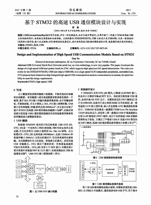
关键词:,FPGA,U盘主控,ASIC,专用处理器,USB,NAND FLASHmaseter of architercture and verification of design based on FPGA UdiskAbstractwith the growing market demand for U disk,the price and function asthe main competition of the manufacturers,U disk unit price difference is small consumers are oftern more concerned with the diversity of functions.Therefore,how to make aUdisk controller more compatibility and scalability,has become the greatest concern of the current master manufacturers.However,due to the confidentiality of commercial technology,coupled with R&D personnel in this area rarely cares and other reasons,leading to U disk erformance is difficult to get quick updates.Deparature from the core of the U disk,in-depth study of the internal structure and design of the main controller chip.Through research amd analysis of the structure by the USB transceiver,USB serial engine,8/16 a dedicated processor ,FIFO controller,NAND Flash ECC controller composition.KEY words;FPGA,Udisk master,ASIC,dedicated processor,USB,nand flash摘要 21 U盘 41.1 U盘概要 41.2 U盘主控方案 51.3 FLASH晶片类型 52 协议概要 52.1 ULPI协议 52.1.1 ULPI主要功能及原理 62.1.2工作模式82.1.3 UMTI+特性82.1.4 传输与接收命令92.2 USB Mass storage协议102.2.1命令块数据包(CBW) 102.2.2命令状态包(CSW) 122.2.3 19种指令132.2.4 U盘初始化流程命令: 143 U盘系统架构153.1系统架构对比15由于USB接口流程复杂,且涉及很多电气规范,本文则不讨论XCVR和SIE。
UTMI+ Low Pin Interface (ULPI)SpecificationRevision 1.1October 20, 2004Revision HistoryDate CommentRevision Issue0.9 November 12, 2003 Pre-release.1.0rc1 January 3, 2004 Introduce PHY interface “modes”.Update interface timings. Clarify 4-bit data clocking.Clarify sending of RX CMD’s and interrupts.Introduce AutoResume feature.Route int pin to data(3) during 6-pin Serial Mode.Explain VBUS thresholds.Add T&MT diagram and updated text.Add new section to explain how PHY is aborted by Link.Various clarifications.1.0rc2 January 13, 2004 Add block diagram.Tighten interface timing.Modify suspend protocol to more closely resemble UTMI.Add SPKR_L and SPKR_MIC to signal list and T&MTconnector.Various clarifications.1.0rc3 January 19, 2004 Specify that PHY must send RX CMD after Reset.Link + PHY clock startup time of no more than 5.6ms for aperipheral is now mandatory.PHY output delay reduced from 10ns to 9ns.Added link decision time numbers for low speed.Various Clarifications.1.0 February 2, 2004 1.0rc3 adopted as 1.0 release.1.1rc1 September 1, 2004 Various clarifications and fixes to hold time numbers, sendingRXCMDs, FsLsSerialMode, Vbus control and monitoring,Test_J and Tesk_K signalling, Low Power Mode,Hostdisconnect, ID detection, HS SOF packets, interrupts,Carkit Mode, interface protection, No SYNC/EOP mode,linestate filtering, and AutoResume.1.1rc2 October 4, 2004 Re-arranged text in section 3.8.7.3. Updated contributors list.1.1 October 20, 2004 1.1rc2 adopted as 1.1 release.The present Specification has been circulated for the sole benefit of legally-recognized Promoters, Adopters and Contributors of the Specification. All rights are expressly reserved, including but not limited to intellectual property rights under patents, trademarks, copyrights and trade secrets. The respective Promoter's, Adopter's or Contributor's agreement entered into by Promoters, Adopters and Contributors sets forth their conditions of use of the Specification.iiPromotersARC International Inc.Conexant Systems, Inc.Mentor Graphics CorporationPhilipsSMSCTransDimension, Inc.ContributorsVertenten PhilipsBartOkur PhilipsBatuhanBillAnderson MotorolaMcInerney TransDimensionBillBooker CypressBrianARCBelangerChrisKolb ARCChrisChrisSchell PhilipsChung Wing Yan PhilipsSrokaPhilipsDaveWang PhilipsDavidWooten TransDimensionDavidSMSCEricKawamotoPhilipsMackayFarranFrazier ConexantFrankFredRoberts SynopsysFarooqConexantHassanLee TransDimensionHyunParr MentorIanStandiford TransDimensionJayPhilipsTjiaJeromeMentorSaundersMarkMohamed Benromdhane ConexantSMSCMorganMonksISINabilTaklaTengstrand ARCPeterRamanand Mandayam ConexantDouglas MentorRobSaleemMohamed Synopsys(Author)ShaunReemeyer PhilipsCypressSimonNguyenSubramanyam Sankaran PhilipsTexasInstrumentsViningSueRemple QualcommTerryChen ConexantTimothyConexantChangVincentQuestions should be emailed to lpcwg@.iiiTable of Contents1.Introduction (1)1.1General (1)1.2Naming Convention (1)1.3Acronyms and Terms (1)1.4References (1)2.Generic Low Pin Interface (2)2.1General (2)2.2Signals (2)2.3Protocol (3)2.3.1Bus Ownership (3)2.3.2Transferring Data (3)2.3.3Aborting Data (4)3.UTMI+ Low Pin Interface (5)3.1General (5)3.2Signals (6)3.3Block Diagram (7)3.4Modes (9)3.5Power On and Reset (10)3.6Interrupt Event Notification (10)3.7Timing (11)3.7.1Clock (11)3.7.2Control and Data (13)3.8Synchronous Mode (15)3.8.1ULPI Command Bytes (15)3.8.2USB Packets (18)3.8.3Register Operations (30)3.8.4Aborting ULPI Transfers (37)3.8.5USB Operations (39)3.8.6Vbus Power Control (internal and external) (52)3.8.7OTG Operations (52)3.9Low Power Mode (55)3.9.1Data Line Definition For Low Power Mode (55)3.9.2Entering Low Power Mode (55)3.9.3Exiting Low Power Mode (56)3.9.4False Resume Rejection (57)3.10Full Speed / Low Speed Serial Mode (Optional) (58)3.10.1Data Line Definition For FsLsSerialMode (58)3.10.2Entering FsLsSerialMode (59)3.10.3Exiting FsLsSerialMode (60)3.11Carkit Mode (Optional) (61)3.12Safeguarding PHY Input Signals (62)4.Registers (65)4.1Register Map (65)4.2Immediate Register Set (67)4.2.1Vendor ID and Product ID (67)4.2.2Function Control (68)4.2.3Interface Control (69)4.2.4OTG Control (71)4.2.5USB Interrupt Enable Rising (72)4.2.6USB Interrupt Enable Falling (73)4.2.7USB Interrupt Status (74)4.2.8USB Interrupt Latch (75)4.2.9Debug (76)4.2.10Scratch Register (76)4.2.11Carkit Control (77)4.2.12Carkit Interrupt Delay (77)iv4.2.13Carkit Interrupt Enable (78)4.2.14Carkit Interrupt Status (78)4.2.15Carkit Interrupt Latch (79)4.2.16Carkit Pulse Control (79)4.2.17Transmit Positive Width (80)4.2.18Transmit Negative Width (80)4.2.19Receive Polarity Recovery (80)4.2.20Reserved (81)4.2.21Access Extended Register Set (81)4.2.22Vendor-specific (81)4.3Extended Register Set (81)4.4Register Settings for all Upstream and Downstream signalling modes (81)5.T&MT Connector (83)5.1General (83)5.2Daughter-card (UUT) Specification (83)vFiguresFigure 1 – LPI generic data bus ownership (3)Figure 2 – LPI generic data transmit followed by data receive (3)Figure 3 – Link asserts stp to halt receive data (4)Figure 4 – Creating a ULPI system using wrappers (5)Figure 5 – Block diagram of ULPI PHY (7)Figure 6 – Jitter measurement planes (12)Figure 7 – ULPI timing diagram (13)Figure 8 – Clocking of 4-bit data interface compared to 8-bit interface (14)Figure 9 – Sending of RX CMD (17)Figure 10 – USB data transmit (NOPID) (18)Figure 11 – USB data transmit (PID) (19)Figure 12 – PHY drives an RX CMD to indicate EOP (FS/LS LineState timing not to scale) (20)Figure 13 – Forcing a full/low speed USB transmit error (timing not to scale) (21)Figure 14 – USB receive while dir was previously low (22)Figure 15 – USB receive while dir was previously high (23)Figure 16 – USB receive error detected mid-packet (24)Figure 17 – USB receive error during the last byte (25)Figure 18 – USB HS, FS, and LS bit lengths with respect to clock (26)Figure 19 – HS transmit-to-transmit packet timing (29)Figure 20 – HS receive-to-transmit packet timing (29)Figure 21 – Register write (30)Figure 22 – Register read (31)Figure 23 – Register read or write aborted by USB receive during TX CMD byte (31)Figure 24 – Register read turnaround cycle or Register write data cycle aborted by USB receive (32)Figure 25 – USB receive in same cycle as register read data. USB receive is delayed (33)Figure 26 – Register read followed immediately by a USB receive (33)Figure 27 – Register write followed immediately by a USB receive during stp assertion (34)Figure 28 – Register read followed by a USB receive (34)Figure 29 – Extended register write (35)Figure 30 – Extended register read (35)Figure 31 – Extended register read aborted by USB receive during extended address cycle (36)Figure 32 – PHY aborted by Link asserting stp. Link performs register write or USB transmit (37)Figure 33 – PHY aborted by Link asserting stp. Link performs register read (38)Figure 34 – Link aborts PHY. Link fails to drive a TX CMD. PHY re-asserts dir (38)Figure 35 – Hi-Speed Detection Handshake (Chirp) sequence (timing not to scale) (40)Figure 36 – Preamble sequence (D+/D- timing not to scale) (41)Figure 37 – LS Suspend and Resume (timing not to scale) (43)Figure 38 – FS Suspend and Resume (timing not to scale) (44)Figure 39 – HS Suspend and Resume (timing not to scale) (46)Figure 40 – Low Speed Remote Wake-Up from Low Power Mode (timing not to scale) (47)Figure 41 – Full Speed Remote Wake-Up from Low Power Mode (timing not to scale) (48)Figure 42 – Hi-Speed Remote Wake-Up from Low Power Mode (timing not to scale) (49)Figure 43 – Automatic resume signalling (timing not to scale) (50)Figure 44 – USB packet transmit when OpMode is set to 11b (51)Figure 45 – RX CMD V A_VBUS_VLD ≤Vbus indication source (54)Figure 46 – Entering low power mode (55)Figure 47 – Exiting low power mode when PHY provides output clock (56)Figure 48 – Exiting low power mode when Link provides input clock (56)Figure 49 – PHY stays in Low Power Mode when stp de-asserts before clock starts (57)Figure 50 – PHY re-enters Low Power Mode when stp de-asserts before dir de-asserts (57)Figure 51 – Interface behaviour when entering Serial Mode and clock is powered down (59)Figure 52 – Interface behaviour when entering Serial Mode and clock remains powered (59)Figure 53 – Interface behaviour when exiting Serial Mode and clock is not running (60)Figure 54 – Interface behaviour when exiting Serial Mode and clock is running (60)Figure 55 – PHY interface protected when the clock is running (62)Figure 56 – Power up sequence when PHY powers up before the link. Interface is protected (63)Figure 57 – PHY automatically exits Low Power Mode with interface protected (63)Figure 58 – Link resumes driving ULPI bus and asserts stp because clock is not running (64)viFigure 59 – Power up sequence when link powers up before PHY (ULPI 1.0 compliant links) (64)Figure 60 – Recommended daughter-card configuration (not to scale) (83)viiTablesTable 1 – LPI generic interface signals (2)Table 2 – PHY interface signals (6)Table 3 – Mode summary (9)Table 4 – Clock timing parameters (11)Table 5 – ULPI interface timing (13)Table 6 – Transmit Command (TX CMD) byte format (15)Table 7 – Receive Command (RX CMD) byte format (16)Table 8 – USB specification inter-packet timings (26)Table 9 – PHY pipeline delays (27)Table 10 – Link decision times (28)Table 11 – OTG Control Register power control bits (52)Table 12 – Vbus comparator thresholds (52)Table 13 – RX CMD VbusValid over-current conditions (53)Table 14 – Vbus indicators in the RX CMD required for typical applications (54)Table 15 – Interface signal mapping during Low Power Mode (55)Table 16 – Serial Mode signal mapping for 6-pin FsLsSerialMode (58)Table 17 – Serial Mode signal mapping for 3-pin FsLsSerialMode (58)Table 18 – Carkit signal mapping (61)Table 19 – Register map (66)Table 20 – Register access legend (67)Table 21 – Vendor ID and Product ID register description (67)Table 22 – Function Control register (68)Table 23 – Interface Control register (70)Table 24 – OTG Control register (71)Table 25 – USB Interrupt Enable Rising register (72)Table 26 – USB Interrupt Enable Falling register (73)Table 27 – USB Interrupt Status register (74)Table 28 – USB Interrupt Latch register (75)Table 29 – Rules for setting Interrupt Latch register bits (75)Table 30 – Debug register (76)Table 31 – Scratch register (76)Table 32 – Carkit Control Register (77)Table 33 – Carkit Interrupt Delay register (77)Table 34 – Carkit Interrupt Enable register (78)Table 35 – Carkit Interrupt Status Register (78)Table 36 – Carkit Interrupt Latch register (79)Table 37 – Carkit Pulse Control (79)Table 38 – Transmit Positive Width (80)Table 39 – Transmit Negative Width (80)Table 40 – Receive Polarity Recovery (81)Table 41 – Upstream and downstream signalling modes (82)Table 42 – T&MT connector pin view (84)Table 43 – T&MT connector pin allocation (84)Table 44 – T&MT pin description (85)viii1. Introduction1.1 GeneralThis specification defines a generic PHY interface in Chapter 2.In Chapter 3, the generic interface is applied to the UTMI+ protocol, reducing the pin count for discrete USB transceiver implementations supporting On-The-Go, host, and peripheral application spaces.Convention1.2 NamingEmphasis is placed on normal descriptive text using underlined Arial font, e.g. must.Signal names are represented using the lowercase bold Arial font, e.g. clk.Registers are represented using initial caps, bold Arial font, e.g. OTG Control.Register bits are represented using initial caps, bold italic Arial font, e.g. USB Interrupt Enable Falling. 1.3 Acronyms and TermsA-device Device with a Standard-A or Mini-A plug inserted into its receptacleB-device Device with a Standard-B or Mini-B plug inserted into its receptacleDeviceDRD Dual-RoleFPGA Field Programmable Gate ArraySpeedFS FullHNP Host Negotiation ProtocolHS Hi-SpeedLink ASIC, SIE, or FPGA that connects to an ULPI transceiverLPI Low Pin InterfaceSpeedLS LowOTG On-The-GoPHY Physical Layer (Transceiver)PLL Phase Locked LoopSE0 Single Ended ZeroSIE Serial Interface EngineSRP Session Request ProtocolT&MT Transceiver and Macrocell TesterULPI UTMI+ Low Pin InterfaceUSB Universal Serial BusUSB-IF USB Implementers ForumUTMI USB 2.0 Transceiver Macrocell InteraceUUT Unit Under Test1.4 References[Ref 1] Universal Serial Bus Specification, Revision 2.0[Ref 2] On-The-Go Supplement to the USB 2.0 Specification, Revision 1.0a[Ref 3] USB 2.0 Transceiver Macrocell Interface (UTMI) Specification, v1.05[Ref 4] UTMI+ Specification, Revision 1.0[Ref 5] CEA-2011, OTG Transceiver Specification[Ref 6] CEA-936A, Mini-USB Analog Carkit Interface Specification[Ref 7] USB 2.0 Transceiver and Macrocell Tester (T&MT) Interface Specification, Version 1.212. Generic Low Pin Interface2.1 GeneralThis section describes a generic low pin interface (LPI) between a Link and a PHY. Interface signals are defined and the basic communication protocol is described. The generic interface can be used as a common starting point for defining multiple application-specific interfaces.Chapter 3 defines the UTMI+ Low Pin Interface (ULPI), which is based on the generic interface described here. For ULPI implementations, the definitions in chapter 3 over-ride anything defined in chapter 2.2.2 SignalsThe LPI transceiver interface signals are described in Table 1. The interface described here is generic, and can be used to transport many different data types. Depending on the application, the data stream can be used to transmit and receive packets, access a register set, generate interrupts, and even redefine the interface itself. All interface signals are synchronous when clock is toggling, and asynchronous when clock is not toggling. Data stream definition is application-specific and should be explicitly defined for each application space for inter-operability.Control signals dir, stp, and nxt are specified with the assumption that the PHY is the master of the data bus. If required, an implementation can define the Link as the master. If the Link is the master of the interface, the control signal direction and protocol must be reversed.Signal Direction DescriptionPHY Interfaceclock I/O Interface clock. Both directions are allowed. All interface signals are synchronous to clock.data I/O Bi-directional data bus, driven low by the Link during idle. Bus ownership is determined by dir. The Link and PHY initiate data transfers by driving a non-zero pattern onto the data bus. LPI defines interface timing for single-edge data transfers with respect to rising edge of clock. An implementation may optionally define double-edge data transfers with respect to both rising and falling edges of clock.dir OUT Direction. Controls the direction of the data bus. When the PHY has data to transfer to the Link, it drives dir high to take ownership of the bus. When the PHY has no data to transfer it drives dir low and monitors the bus for Link activity. The PHY pulls dir high whenever the interface cannot accept data from the Link. For example, when the internal PHY PLL is not stable.stp IN Stop. The Link asserts this signal for 1 clock cycle to stop the data stream currently on the bus. If the Link is sending data to the PHY, stp indicates the last byte of data was on the bus in the previous cycle. If the PHY is sending data to the Link, stp forces the PHY to end its transfer, de-assert dir and relinquish control of the the data bus to the Link.nxt OUT Next. The PHY asserts this signal to throttle the data. When the Link is sending data to the PHY, nxt indicates when the current byte has been accepted by the PHY. The Link places the next byte on the data bus in the following clock cycle. When the PHY is sending data to the Link, nxt indicates when a new byte is available for the Link to consume.Table 1 – LPI generic interface signals22.3 ProtocolOwnership2.3.1 BusThe PHY is the master of the LPI bi-directional data bus. Ownership of the data bus is determined by the dir signal from the PHY, as shown in Figure 1. When dir is low, the Link can drive data on the bus. When dir is high, the PHY can drive data on the bus. A change in dir causes a turnaround cycle on the bus during which, neither Link nor PHY can drive the bus. Data during the turnaround cycle is undefined and must be ignored by both Link and PHY.The dir signal can be used to directly control the data output buffers of both PHY and Link.Figure 1 – LPI generic data bus ownershipData2.3.2 TransferringAs shown in the first half of Figure 2, the Link continuously drives the data bus to 00h during idle. The Link transmits data to the PHY by driving a non-zero value on the data bus. To signal the end of data transmission, the Link asserts stp in the cycle following the last data byte.In the second half of Figure 2, the Link receives data when the PHY asserts dir. The PHY asserts dir only when it has data to send to the Link, and keeps dir low at all other times. The PHY drives data to the Link after the turnaround cycle.The nxt signal can be used by the PHY to throttle the data during transmit and receive. During transmit, nxt may be asserted in the same cycle that the Link asserts stp.Figure 2 – LPI generic data transmit followed by data receive2.3.3 AbortingDataThe PHY can assert dir to interrupt any data being transmitted by the Link. If the Link needs to interrupt data being received from the PHY, it asserts stp for one clock cycle, as shown in Figure 3. This causes the PHY to unconditionally1 de-assert dir and accept a complete data transmit from the Link. The PHY may re-assert dir again only when the data transmit from the Link has completed.Figure 3 – Link asserts stp to halt receive data1 The PHY will not de-assert dir if the ULPI interface is not usable. For example, if the internal PLL is not stable.3. UTMI+ Low Pin Interface3.1 GeneralThis section describes how any UTMI+ core can be wrapped to convert it to the smaller LPI interface. The generic interface described in chapter 2 is used as a starting point. This section always over-rides anything stated in chapter 2. While this specification details support of UTMI+ Level 3, PHY implementers may choose to support any of the Levels defined in UTMI+.ULPI defines a PHY to Link interface of 8 or 12 signals that allows a lower pin count option for connecting to an external transceiver that may be based on the UTMI+ specification. The pin count reduction is achieved by having relatively static UTMI+ signals be accessed through registers and by providing a bi-directional data bus that carries USB data and provides a means of accessing register data on the ULPI transceiver.This specification relies on concepts and terminology that are defined in the UTMI+ specification [Ref 4]. Specifically, if a ULPI PHY design is based on an internal UTMI+ core, then that core must implement the following UTMI+ features.Linestate must accurately reflect D+/D- to within 2-3 clocks. It is up to individual Link designers to use Linestate to time bus events.Filtering to prevent spurious SE0/SE1 states appearing on Linestate due to skew between D+ and D-. Filtering of 14 clock cycles is required in Low Speed, and 2 clock cycles in Full Speed and Hi-Speed modes.The PHY must internally block the USB receive path during transmit. The receive path can be unblocked when the internal Squelch (HS) or SE0-to-J (FS/LS) is seen.TxReady must be used for all types of data transmitted, including Chirp.Due to noise on the USB, it is possible that RxActive asserts and then de-asserts without any valid data being received, and RxValid will not assert. The Link should operate normally with these data-less RxActive assertions.As shown in Figure 4, a PHY or Link based on this specification can be implemented as an almost transparent wrapper around existing UTMI+ IP cores, preserving the original UTMI+ packet timing, while reducing pin count and leaving all functionality intact. This should not be taken to imply that other implementations are not possible.Figure 4 – Creating a ULPI system using wrappers3.2 SignalsTable 2 describes the ULPI interface on the PHY. The PHY is always the master of the ULPI bus. USB and Miscellaneous signals may vary with each implementation and are given only as a guide to PHY designers.Signal Direction DescriptionPHY Interfaceclock I/O Interface clock. The PHY must be capable of providing a 60MHz output clock. Support for an input 60MHz clock is optional. If the PHY supports both clock directions, it must not use the ULPI control and data signals for setting the clock direction.Data bus. Driven to 00h by the Link when the ULPI bus is idle. Two bus widths are allowed:• 8-bit data timed on rising edge of clock.data I/O• (Optional) 4-bit data timed on rising and falling edges of clock.dir OUT Controls the direction of the data bus2. The PHY pulls dir high whenever the interface cannot accept data from the Link. For example, when the internal PLL is not stable. This applies whether Link or PHY is the clock source.stp IN The Link must assert stp to signal the end of a USB transmit packet or a register write operation, and optionally to stop any receive. The stp signal must be asserted in the cycle after the last data byte is presented on the bus.nxt OUT The PHY asserts nxt to throttle all data types, except register read data and the RX CMD. Identical to RxValid during USB receive, and TxReady during USB transmit. The PHY also asserts nxt and dir simultaneously to indicate USB receive activity (RxActive), if dir was previously low. The PHY is not allowed to assert nxt during the first cycle of the TX CMD driven by the Link.USB InterfaceD+ I/O D+ pin of the USB cable. Required.D- I/O D- pin of the USB cable. Required.ID IN ID pin of the USB cable. Required for OTG-capable PHY’s.VBUS I/O V BUS pin of the USB cable. Required for OTG-capable PHY’s. Required for driving V BUS and the V BUS comparators.MiscellaneousXI IN Crystal input pin. Vendors should specify supported crystal frequencies. XO OUT Crystal output pin.C+ I/O Positive terminal of charge pump capacitor.C- I/O Negative terminal of charge pump capacitor.SPKR_L IN Optional Carkit left/mono speaker input signal.SPKR_MIC I/O Optional Carkit right speaker input or microphone output signal.RBIAS I/O Bias current resistor.Table 2 – PHY interface signals2 UTMI+ wrapper developers should note that data bus control has been reversed from UTMI to ensure that USB data reception is not interrupted by the Link.3.3 BlockDiagramAn example block diagram of a ULPI PHY is shown in Figure 5. This example is based on an internal UTMI+ Level 3 core [Ref 4], which can interface to peripheral, host, and On-The-Go Link cores. A description of each major block is given below.ULPI InterfaceUSBCableChargePumpCapacitor Figure 5 – Block diagram of ULPI PHYUTMI+ Level 3 PHY coreThe ULPI PHY may contain a core that is compliant to any UTMI+ level [Ref 4]. Signals for 16-bit data buses are not supported in ULPI. While Figure 5 shows the typical blocks for a Level 3 UTMI+ core, the PHY vendor must specify the intended UTMI+ level, and provide the functionality necessary for compliance to that level.ULPI PHY WrapperThe ULPI PHY wrapper of Figure 5 reduces the UTMI+ interface to the Low Pin Interface described in this document. All signals shown on the UTMI+ Level 3 PHY core are reduced to the ULPI interface signals clock, data, dir, stp, and nxt. The Register Map stores the relatively static signals of the UTMI+ interface. Crystal Oscillator and PLLWhen a crystal is attached to the PHY, the internal clock(s) and the external 60MHz interface clock are generated from the internal PLL. When no crystal is attached, the PHY may optionally generate the internal clock(s) from an input 60MHz clock provided by the Link.General BiasingInternal analog circuits require an accurate bias current. This is typically generated using an external, accurate reference resistor.DrvVbusExternal and ExternalVbusIndicatorThe PHY may optionally control an external VBUS power source via the optional pin DrvVbusExternal. For example, the external supply could be a charge pump or 5V power supply controlled using a power switch. The external supply is controlled by the DrvVbus and the optional DrvVbusExternal bits in the OTG Control register. The polarity of the DrvVbusExternal output pin is implementation dependent.If control of an external VBUS source is provided the PHY may optionally provide for a VBUS power source feed back signal on the optional pin ExternalVbusIndicator. If this pin is provided, the use of the pin is defined by the optional control bits in the OTG Control and Interface Control registers. See Section 3.8.6.3 for further detail.Power-On-ResetA power-on-reset circuit must be provided in the PHY. When power is first applied to the PHY, the power-on-reset will reset all circuitry and leave the ULPI interface in a usable state.Carkit OptionThe PHY may optionally support Carkit Mode [Ref 6]. While in Carkit Mode, the PHY routes speaker and microphone signals between the Link and the USB cable. In carkit mono mode, SPKR_L inputs a mono speaker signal and SPKR_MIC outputs the microphone signal, MIC. In carkit stereo mode, SPKR_L inputs the left speaker signal, and SPKR_MIC inputs the right speaker signal, SPKR_R.3.4 ModesThe ULPI interface can operate in one of five independent modes listed in Table 3. The interface is in Synchronous Mode by default. Other modes are enabled by bits in the Function Control and Interface Control registers. In Synchronous Mode, the data bus carries commands and data. In other modes, the data pins are redefined with different functionality. Synchronous Mode and Low Power Mode are mandatory.Mode Name Mode DescriptionSynchronous Mode This is the normal mode of operation. The clock is running and is stablewith the characteristics defined in section 3.6. The ULPI interface carriescommands and data that are synchronous to clock.Low Power Mode The PHY is powered down with the clock stopped. The PHY keeps dirasserted, and the data bus is redefined to carry LineState and interrupts.See section 3.9 for more information.6-pin FS/LS Serial Mode (optional) The data bus is redefined to 6-pin serial mode, including 6 pins to transmit and receive serial USB data, and 1 pin to signal interrupt events. The clock can be enabled or disabled. This mode is valid only for implementations with an 8-bit data bus. See section 3.10 for more information.3-pin FS/LS Serial Mode (optional) The data bus is redefined to 3-pin serial mode, including 3 pins to transmit and receive serial USB data, and 1 pin to signal interrupt events. The clock can be enabled or disabled. See section 3.10 for more information.Carkit Mode (optional) The data bus is redefined to Carkit mode [Ref 6], including 2 pins for serial UART data, and 1 pin to signal interrupt events. The clock may optionally be stopped. See section 3.11 for more information.Table 3 – Mode summary。

关于攀登珠穆朗玛峰的英语范例Mount Everest, the towering giant of the Himalayas, beckons adventurers from around the globe with its mystique and challenge. The allure of summiting the world's highest peak, standing at a staggering 8,848 meters above sea level, is a dream shared by many, yet achieved by few. Embarking on an expedition to climb Mount Everest is a monumental undertaking, requiring meticulous planning, physical endurance, mental fortitude, and a deep respect for the mountain's formidable power.The journey to the summit of Everest begins long before setting foot on its icy slopes. Months, if not years, of preparation are essential to increase the chances of a successful ascent and ensure the safety of climbers. Physical training is paramount, with climbers focusing on building strength, endurance, and agility to navigate the treacherous terrain of the Himalayas. Cardiovascular exercises, strength training, and high-altitude simulation are all integral components of a climber's fitness regimen.Equally important is mental preparation. Climbing Everest is as much a test of mental resilience as it is physical prowess. The extreme altitude, harsh weather conditions, and inherent risks of high-altitude mountaineering demand unwavering determination and mental discipline. Climbers must cultivate a mindset of adaptability, perseverance, and humility, recognizing that the mountain is ultimately in control.Logistical planning is another critical aspect of preparing for an Everest expedition. From securing permits and organizing logistics to assembling a skilled team of Sherpas, guides, and support staff, every detail must be carefully orchestrated to ensure a smooth and safe ascent. Experienced mountaineering outfitters play a vital role in coordinating the myriad logistics involved in a Himalayan expedition, providing climbers with essential support services, equipment, and expertise.As climbers make their way through the Khumbu Valley and ascend the flanks of Everest, they are greeted by a landscape of breathtaking beauty and unforgiving terrain.The Khumbu Icefall, notorious for its towering seracs and precarious ice bridges, poses one of the most significant challenges of the climb. Navigating this ever-shifting maze of ice requires skill, concentration, and a healthy dose of courage.Above the Icefall lies the Western Cwm, a vast, bowl-shaped valley of snow and ice flanked by towering peaks. Climbers must carefully pace themselves as they ascend through the thin air of the high Himalayas, acclimatizing to the altitude and conserving their energy for the final push to the summit.The final leg of the ascent takes climbers along the Southeast Ridge, a narrow and exposed route that teststheir endurance and resolve. Battling fatigue, altitude sickness, and the biting cold, climbers inch their way closer to the summit with each arduous step. The infamous Hillary Step, a near-vertical rock face just below the summit, presents one last formidable obstacle before reaching the rooftop of the world.Standing atop the summit of Mount Everest is a moment of unparalleled triumph and humility. Surrounded by the vast expanse of the Himalayas, with the world spread out below, climbers experience a profound sense of awe and reverence. Yet, the summit is only half the journey, and the descent presents its own set of challenges and dangers.Descending safely from the summit is imperative, as fatigue and altitude-related illnesses can pose significant riskson the descent. Climbers must carefully monitor their physical and mental condition, pacing themselves as they make their way back down the mountain. The support and expertise of Sherpas and guides are invaluable during this critical phase of the expedition, providing assistance and guidance to ensure a safe return to base camp.Reaching the safety of base camp marks the end of an epic journey, but the memories and lessons learned on Everestwill endure a lifetime. The mountain has a way of leavingan indelible mark on those who dare to challenge its slopes, instilling a profound respect for the power and majesty of the natural world. As climbers reflect on their journey,they are reminded that true greatness lies not in conquering mountains, but in the humility and reverence with which we approach them.。
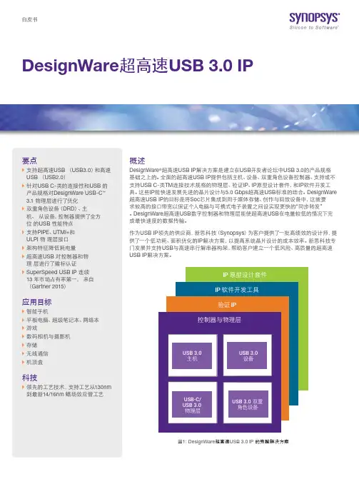
白皮书DesignWare超高速USB 3.0 IP要点``支持超高速USB (USB3.0)和高速USB (USB2.0)``针对USB C-类的连接性和USB 的产品规格对DesignWare USB-C™3.1 物理层进行了优化``双重角色设备(DRD)、主机、从设备,控制器提供了全方位的USB 性能特点``支持PIPE、UTMI+和ULPI 物理层接口``架构特征降低耗电量``超高速USB 对控制器和物理层进行了徽标认证``SuperSpeed USB IP 连续13 年市场占有率第一,来自(Gartner 2015)应用目标``智能手机``平板电脑、超级笔记本、网络本``游戏``数码相机与摄影机``存储``无线通信``机顶盒科技``领先的工艺技术,支持工艺从130nm到最新14/16nm 鳍场效应管工艺概述DesignWare®超高速USB IP解决方案是建立在USB开发者论坛中USB 3.0的产品规格基础之上的。
全面的超高速USB IP提供包括主机、设备、双重角色设备控制器、支持或不支持USB C-类TM连接技术规格的物理层、验证IP、IP原型设计套件,和IP软件开发工具。
这些IP能快速发展先进的晶片设计与5.0 Gbps超高速USB标准的结合。
DesignWare超高速USB IP的目标是将Soc芯片集成到用于媒体存储、创作与回放设备中,这就要求较高的接口带宽以保证个人电脑与可携式电子装置之间设实现更快的“同步转发”。
DesignWare超高速USB数字控制器和物理层能使超高速USB在电量较低的情况下完成最快速度的数据传输。
作为USB IP领先的供应商,新思科技(Synopsys)为客户提供了一批高绩效的设计师,提供了一个低功耗、面积优化的IP解决方案,以提高系统晶片设计的成本效率。
新思科技专门发展并支持USB与高速串行解串器构架,帮助客户建立一个低风险、高质量的超高速USB IP解决方案。

UTMI+ SpecificationRevision 1.0Revision HistoryRevision Issue Date Comment0.7 April 24th, 2002 Initial version0.71 April 29th, 2002 Reworked the different levels0.72 June 4th, 2002 Extended definition of OpModeAdded outline on how to implement multi-port host controllers usingUTMI+0.8 June 17th, 2002 Promoted to version 0.8 to allow review by OTG workgroup members0.81 July 3rd, 2002 Clarified Optional charge pump, rewording for grammer and clarity0.82 July 22nd, 2002 Added signal IdPullupAdded signal FsSerialMode and legacy interface signalsAdded signal TxBitstuffEnable / TxBitstuffEnableHRemoved signal SessEnd0.83 October 23rd, 2002 Changed FsSerialMode into FsLsSerialModeAdded SessEnd signal back because there is still uncertainty that anOTG system will work without this signal in all conditions.Added clarifications0.9rc January 8th, 2003 Added clarification of long EOP generationModified suspend/resume behaviour in host modeChanged IdPullup timingAdded chapter on T&MT connector0.9rc2 January 17th, 2003 Added section on ambiguities in UTMI v1.05 specAdded clarification on HostDisconnect signal when PHY is in suspend0.9rc3 February 7th, 2003 Changed TermSelect definition for LS devicesChanged clarification for RxActive/RxValid during transmitAdded clarification for LineState0.9 February 21st, 2003 Added more clarification to LineStatePromoted to version 0.9 by OTG workgroup0.91 October 13th, 2003 Changed time between IdPullup being asserted and IdDig having a validvalue.Updated LineState tablesChanged behaviour of OpMode during chirp sequenceUpdated disclaimer0.92 November 13th, 2003 Changed time T1 during resume to be minimum 16 LS bit times. Thisallows the transceiver to complete the resume signaling in a correctway.1.0 February 25th, 2004 Version approved by the Promoters and Adopters of UTMI+/ULPI"The present Specification has been circulated for the sole benefit of legally-recognized Promoters, Adopters and Contributors of the Specification. All rights are expressly reserved, including but not limited to intellectual property rights under patents, trademarks, copyrights and trade secrets. The respective Promoter's, Adopter'sor Contributor's agreement entered into by Promoters, Adopters and Contributors sets forth their conditions of use of the Specification."Table of Contents1.Introduction (6)1.1Purpose (6)1.2Audience (6)1.3Disclaimers (6)1.4Relevant Documents (6)2.Definition of Different levels (7)2.1UTMI+ level 0 : USB2.0 peripherals (7)2.1.1Additional requirements and clarifications on top of UTMI (8)2.2UTMI+ level 1 : USB2.0 peripherals, host controllers and On-the-Go devices (HS and FS only) (9)2.2.1Additional signals for UTMI+ level 1 (9)2.2.2Generation of long EOP (15)2.2.3Data line pulsing (16)2.2.4HS keep-alive generation (16)2.2.5UTMI+ level 1 transceiver core used in a USB2.0 peripheral (17)2.3UTMI+ level 2 : USB2.0 peripherals, host controllers and On-the-Go devices (HS / FS / LS / no hubsupport) (17)2.3.1XcvrSelect(1:0) (18)2.3.2LS keep-alive generation (19)2.3.3LineState (19)2.4UTMI+ level 3 : USB2.0 peripherals, host controllers and On-the-Go devices (HS / FS / LS / preamble)202.4.1XcvrSelect(1:0) (20)2.4.2Multi-port host controllers (21)3.Explanation of different signaling modes (22)3.1Chirp sequence (22)3.2Suspend / Resume signaling for downstream facing ports (22)3.3Transmit error reporting for downstream facing ports (24)3.4Selection of different signaling modes for upstream and downstream facing ports (25)4.T&MT Connector (26)FiguresFigure 1 : UTMI+ levels (7)Figure 2 : UTMI+ level 0 entity diagram (16-bit interface) (8)Figure 3 : UTMI+ level 1 entity diagram (10)Figure 4 : HostDisconnect behaviour (signals are not on scale) (14)Figure 5 : Data line pulsing for a Dual-Role B-device (16)Figure 6 : HS keep-alive generation (16)Figure 7 : UTMI+ level 2 entity diagram (18)Figure 8 : LS keep-alive generation (19)Figure 9 : Reset sequence for a HS peripheral connected to a HS Host Controller (22)Figure 10 : Resume signaling on downstream facing ports (23)Figure 11 : Transmit error reporting for downstream facing ports (24)TablesTable 1 : Filtering of LineState (9)Table 2 : UTMI+ level 1 transceiver core used in a USB2.0 peripheral (17)Table 3 : LineState for upstream facing ports (DpPulldown and DmPulldown = 0) (20)Table 4 : LineState for downstream facing ports(DpPulldown and DmPulldown = 1) (20)Table 5 : Different signaling modes for upstream and downstream facing ports (25)Table 6 : T&MT connector pinning[1] (26)Acronyms and TermsFS Full-SpeedHS High-SpeedIC Integrated CircuitLS Low-SpeedOTG On-The-GoSE0 Single Ended ZeroUSB Universal Serial BusUSB-IF USB Implementers ForumUTMI USB 2.0 Transceiver Macrocell InterfaceContributorsBart Vertenten PhilipsSrinivas Pattamatta PhilipsJerome Tjia PhilipsChung Wing Yan PhilipsFarran Mackay PhilipsChris Kolb ARCChristopher Meyers ARCDavid Cobbs CypressDavid Wooten CypressEric Huang SynopsysRavikumar Govindaraman SynopsysSaleem Mohammad SynopsysMichael Pennell SMSCNabil Takla InnovativePaul Berg MCCIPeter Hirt ST MicroelectronicsAlok Kaushik ST MicroelectronicsRob Douglas Mentor GraphicsAndy King Mentor GraphicsZong Liang Wu TransDimensionHemal Doshi Portalplayer Inc1. Introduction1.1 PurposeThe purpose of this document is to specify an interface to which USB 2.0 ASIC, ASSP, discrete PHY, system peripherals and IP vendors can develop USB2.0 products. The existing UTMI specification describes an interface only for USB2.0 peripherals. The UTMI specification can not be used to develop USB 2.0 host or On-The-Go peripherals. The intention of this UTMI+ specification is to extend the UTMI specification to standardize the interface for USB 2.0 hosts and USB 2.0 On-The-Go peripherals. The UTMI+ specification defines and standardizes the interoperability characteristics with existing USB 2.0 hosts and peripherals.1.2 AudienceThis document is intended for developers and vendors of USB 2.0 ASIC, ASSP, discrete PHY, system, peripheral and IP products.1.3 DisclaimersThis document is a recommendation of the contributors indicated in the title pages. It does not necessarily reflect the position of their respective companies, the OTG working group, or the position of the USB-IF.1.4 Relevant Documents• USB 2.0 Transceiver Macrocell Interface Specification, version 1.05, Steve McGowan, March 29th, 2001• USB 2.0 Transceiver and Macrocell Tester(T&MT) Interface Specification, Wes Talarek, version 1.2, April 4th, 2001• On-The-Go Supplement to the USB 2.0 Specification (/developers/onthego)• USB 2.0 Specification (/developers/docs.html)• OTG Certification Specification Revision 0.7• ECN_27%_ Resistor (/app/members/ecn_html)• OTG Labeling Specification Revision 0.632. Definition of Different levelsThe level of complexity needed for a high-speed USB On-The-Go peripheral can be very different. Especially the complexity needed for the host controller part is very dependent on the targeted peripheral list. Therefore the UTMI+ specification is built up in progressive levels. The base (level 0) for UTMI+ is the UTMI specification version 1.05[1]. Level 1 is targeted for USB On-The-Go Dual-Role-Devices that must be capable of generating HS and FS traffic. Level 2 adds the possibility of generating LS traffic towards LS devices that are directly connected to the USB On-The-Go DRD. Finally, Level 3 adds the possibility to have also USB 2.0 FS hubs in the USB tree and let the host controller part of the USB On-The-Go DRD communicate with LS devices that are connected to the USB FS hub controller.Any transceiver core that is developed to a given level shall be compliant with all levels below that level.In Figure 1, a general overview is given on how the different levels layer on each other.Figure 1 : UTMI+ levels2.1 UTMI+ level 0 : USB2.0 peripheralsThe base of the UTMI+ specification is the UTMI specification version 1.05. This is defined as UTMI+ level 0. The transceiver cores that pretend to be UTMI+ level 0 compliant can be used in a USB2.0 peripheral design. These cores cannot be used to implement USB2.0 Hosts or On-the-Go peripherals without additional logic.Figure 2 : UTMI+ level 0 entity diagram (16-bit interface)During the implementation of UTMI+, it was found that some parts of the UTMI spec were not clearly specified or could be interpreted in different ways. This caused that integration of UTMI transceiver from one vendor with the USB device core from another vendor was not always working. To remove these problems from future designs any core that is UTMI+ compliant must implement the requirements described in section 2.1.1.For more details on how to implement a UTMI+ level 0 transceiver see also the UTMI spec[1]. In Figure 2 a general overview is given of all interface signals needed for UTMI+ level 0 transceiver with 16-bit interface. For a UTMI+ level 0 transceiver with 8-bit interface the TXValidH, RXValidH, DataBus16_8, DataIn(15:8) and DataOut(15:8) signals are not needed.2.1.1 Additional requirements and clarifications on top of UTMI2.1.1.1 Use of LineState for timersThe UTMI spec mentions several times that LineState is the most accurate signal to be used for timing a certain state on the USB bus. It is not a hard requirement for the USB device core designer to use this signal. He can use whatever method he wants as long as correct behavior on the USB bus is guaranteed without forcing additional constraints on the PHY design.2.1.1.2 LineState filteringMinimal filtering should be applied to LineState to ensure that skew on the DP/DM signals does not generate unwanted SE0 or SE1 states between J and K states. For instance, for FS mode Table 7-9 of the USB 2.0 Specification identifies the “Width of SE0 interval during differential transition” to be 14ns max. These SE0 states are noise to the SIE and shouldnot be propagated by LineState. To be able to filter worst case SE0 noise, the transceiver should implement filtering as indicated in Table 1.Filtering should only occur on an SE0. If during filtering the SE0 a non-SE0 event occurs then the filtering should stop and linestate behaviour continues as previously.Bus speed 8-bit interface (CLK = 60MHz) 16-bit interface (CLK = 30 MHz) Low-speed mode filtering 14 CLK cycles 7 CLK cyclesFull-speed mode filtering 2 CLK cycles 1 CLK cycleHigh-speed mode filtering 2 CLK cycles 1 CLK cycleTable 1 : Filtering of LineState2.1.1.3 RxActive/RxValid during transmitThe UTMI PHY must internally block the USB receive path once a USB transmit has begun. The receive path can be unblocked when the internal Squelch (HS) or SE0-to-J (FS/LS) is seen.2.1.1.4 TxReady behavior when not bitstuffingTxReady must be used in chirp mode. If TxReady is not asserted by the UTMI PHY when the USB device core was sending a chirp, it can cause the device core to lock-up if the device core is holding the transmit data on the bus until it sees TxReady asserted. By explicitly requiring that TxReady must be asserted for all transmit data including chirp data, this problem can be avoided.2.1.1.5 Receive End DelayAt the end of page 59 of the UTMI spec v.1.05 there is a contradiction between the number of bit times and the number of clock cycles for Total Receive End Delay for an interface running at 30MHz. 6 30 MHz clock cycles is actually 96 bit times. For a 16 bit transceiver interface, the Total Receive End Delay must be between 32-96 bit times or 2-6, 30 MHz CLKs2.2 UTMI+ level 1 : USB2.0 peripherals, host controllers and On-the-Go devices (HSand FS only)Any transceiver core that has an interface compliant with UTMI+ level 1, has all signals compliant with UTMI+ level 0. A transceiver core with UTMI+ level 1 interface can be used for USB2.0 peripheral, host or On-the-Go device designs that support only HS and FS traffic. If a host controller needs to be able to communicate with a LS device some additional functions are required that are not part of level1 (cfr section 2.3).Transceivers implementing level 1 may optionally include an integrated charge pump to supply VBUS current to the On-The-Go connector. If the charge pump is integrated within the transceiver macrocell then a description of the charge pump must be given in the transceiver datasheet to allow integrators to build a complete USB On-The-Go peripheral. If the charge pump is not integrated within the transceiver macrocell then the optional DrvVbus signal may be omitted from the macrocell.2.2.1 Additional signals for UTMI+ level 1.USB On-The-Go peripherals have some additional capabilities and therefore some new signals need to be implemented.1. A USB On-The-Go dual role peripheral needs to be capable to distinguish between a mini-A and mini-B plug.2. A USB On-The-Go peripheral has to know if Vbus is below or above a certain voltage level.3. A USB On-The-Go peripheral must be able to drive Vbus and charge or discharge Vbus.4. A USB On-The-Go dual role peripheral needs to be able to switch the pull-up resistor on DP and the pull-downresistor on both DP and DM.5. The downstream facing port of a host controller must have 15 kOhm pull-down resistors on both DP and DM lines.Some signals are needed to do the correct switching of the resistors6. The host controller must be able to detect a disconnect of a peripheral. This is possible for a FS peripheral by usingLineState, but it is not possible for HS peripherals using the current UTMI specification. Therefore an additional signal needs to be implemented. To make the design of the digital SIE easier, this new disconnect signal will be used in both speeds (HS/FS) to indicate if there is a device connected or not.In Figure 3 an overview is given of all signals needed for the UTMI+ level 1 interface.Figure 3 : UTMI+ level 1 entity diagram2.2.1.1 IdDig / IdPullupThe id signal is indicating the state of the ID pin on the USB mini receptacle. This pin makes it able to determine which kind of plug is connected. To save power, there is also an IdPullup signal. Only when this IdPullup signal is high, the analog Id line will be sampled and the IdDig signal will indicate the correct value.IdPullup Signal that enables the sampling of the analog Id line.0b : Sampling of Id pin is disabled. IdDig is not valid1b : Sampling of Id pin is enabled.IdDig Indicates whether the connected plug is a mini-A or mini-B. This is only valid when IdPullup is set to 1b. It must be valid within 50ms after IdPullup is set to 1b.0b : connected plug is a mini-A1b : connected plug is a mini-B2.2.1.2 AValidThe AValid signal is used to indicate if the session for an A-peripheral is valid. This signal is 1b when Vbus is above 2V. Avalid Indicates if the session for an A-peripheral is valid (0.8V < Vth < 2V).0b : Vbus < 0.8V1b : Vbus > 2V2.2.1.3 BValidThe BValid signal is used to indicate if the session for a B-peripheral is valid. This signal is 1b when Vbus is above 4V. Bvalid Indicates if the session for an B-peripheral is valid (0.8V < Vth < 4V).0b : Vbus < 0.8V1b : Vbus > 4V2.2.1.4 VbusValidThe VbusValid signal is used to determine whether or not the voltage on Vbus is at a valid level for operation. The minimum threshold for the Vbus comparator is 4.4VVbusValid Indicates if the voltage on Vbus is at a valid level for operation (4.4V < Vth < 4.75V).0b : Vbus < 4.4V1b : Vbus > 4.75V2.2.1.5 SessEndThe SessEnd signal is used to determine if the voltage on Vbus is below its B-Device Session End threshold. SessEnd Indicates if the voltage on Vbus (0.2V < Vth < 0.8V).1b : Vbus < 0.2V0b : Vbus > 0.8VAccording to the definition in the OTG supplement of the USB 2.0 specification, it must be possible to build a USB OTG DRD without the SessEnd signal. The detection can be done in the digital controller section. 50ms after Vbus is discharged, the voltage on Vbus must be below the B-device Session End Threshold. This is correct in a normal working environment. However it is always possible that in systems for some reason the Vbus does not go down to levels less than SessEnd (e.g. standard host, short circuit on the charge pump so that Vbus is always on, etc). Therefore it is seen that this signal is a must and is preferred to be used in order to have a correct working system in all cases.2.2.1.6 DrvVbusThe DrvVbus is an enable signal to drive 5V on Vbus. The DrvVbus signal is optional for transceiver implementations,depending on whether an integrated charge pump is implemented. The DrvVbus signal is mandatory for SIE implementing an interface that is compliant with level 2 of UTMI+.DrvVbus This signal enables to drive 5V on Vbus0b : do not drive Vbus1b : drive 5V on Vbus2.2.1.7 DischrgVbusIf DischrgVbus is active then Vbus will be pulled down through a resistor to ground. This is needed to discharge Vbus before initiating SRP. B-peripherals use this signal to ensure that Vbus is at a low enough voltage before starting SRP. The minimum time that DischrgVbus needs to be asserted is 50 ms.DischrgVbus The signal enables discharging Vbus.1b : discharge Vbus through a resistor (this has to be active for at least 50 ms)0b : do not discharge Vbus through a resistor2.2.1.8 ChrgVbusIf ChrgVbus is active then Vbus will be pulled up through a resistor. This is done to initiate SRP.The minimum time that ChrgVbus needs to be asserted is 30 ms.ChrgVbus The signal enables charging Vbus.1b : charge Vbus through a resistor (this has to be active for at least 30 ms)0b : do not charge Vbus through a resistor2.2.1.9 DpPulldown / DmPulldownDpPulldown This signal enables the 15k Ohm pull-down resistor on the DP line.0b : Pull-down resistor not connected to DP1b : Pull-down resistor connected to DPDmPulldown This signal enables the 15k Ohm pull-down resistor on the DM line.0b : Pull-down resistor not connected to DM1b : Pull-down resistor connected to DMThese two signals are used to switch on the 15k Ohm pull-down resistors on both DP and DM for a host.These signals should not been toggled during normal operation.Using the TermSelect signal can do switching the pull-up resistor for a peripheral.For a peripheral both signals should been set to 0b. For a host controller both signals should been set to 1b.2.2.1.10 HostDisconnectHostDisconnect This signal is used for all types of peripherals connected to it. It is only valid whenDpPulldown and DmPulldown are 1b. If DpPulldown and DmPulldown are not 1b then thebehaviour of HostDisconnect is undefined.As long as there is no peripheral connected, this signal will be 1b. If a peripheral isconnected, then the value of this signal will be 0b.Internally there are two disconnect signals, one that detects disconnect in HS mode and one that detects connect/disconnect in FS mode. Depending on XcvrSelect one of these signals is routed to the actual output port HostDisconnect. If in HS mode a disconnect is detected, the HostDisconnect signal will be set to 1b. At that moment the Macrocell will be switched to FS mode (XcvrSelect = 01b).In FS/LS mode, a disconnect condition occurs if the transceiver detects a SE0 signaling f or 2.5 us and a connect condition occurs if the transceiver detects non-SE0 signaling for 2.5 us. If a disconnect is detected, hostdisconnect is asserted and if a connect is detected it is deasserted.In HS mode, a disconnect condition is evaluated every time a HS SOF packet is sent. If a disconnect is detected, hostdisconnect is asserted.When hostdisconnect is asserted in high-speed mode the transceiver is placed into full-speed mode by the host core. Also when the host core wants to put the USB bus (which has a hi-speed device connected) into suspend mode, it switches the transceiver from hi-speed mode into full-speed mode. At that moment the connected hi-speed device is still in hi-speed and the USB bus state is still in SE0. To prevent false full-speed connect/disconnects, the hostdisconnect signal cannot be updated for 4 ms from the transition into full-speed. After the 4 ms recovery time the status of the full-speed connect/disconnect can be determined and the hostdisconnect signal updated accordingly. The 4 ms of recovery time allows the peripheral device connected to the host to detect the suspend signaling on the USB bus, move into the FS suspend mode and bring the USB bus to the Full Speed Idle state (Jstate).However if the transceiver is put into power down (which can happen for power consumption reasons), the hostdisconnect signal is deasserted immediately (in both cases : device connected or not) and the 4 ms recovery time is not required. The core attached must look at LineState to see if the state of the USB bus changes. If it does, the core should bring the transceiver out of power down and look at the hostdisconnect signal. When the transceiver comes out of power down the hostdisconnect signal must have the correct value within 1 ms after the clock is back up and running.Disconnect of HS peripheralTransition from operational to suspendHS disconnectSOF tokens on USB busHi-speed device Device goes into suspendFigure 4 : HostDisconnect behaviour (signals are not on scale)2.2.1.11 OpModeOpMode(1:0)These signals select between various operational modes :00b : Normal operation (The UTMI+ transceiver automatically appends the SYNC and EOP pattern)01b : Non-driving10b : Disable bit stuffing and NRZI encoding11b : Normal operation without automatic generation of SYNC and EOP. NRZI encoding is always enabled. Bit stuffing depends on the value of TxBitstuffEnable andTxBitstuffEnableH. This is only valid when XcvrSelect is set to 00b. If OpMode is set to 11b together with XcvrSelect not equal to 00b, the behavior of the transceiver is undefined.The extension of OpMode is done to have control on all bits that are sent on the USB bus. This mode has to be used in order to send a HS keep-alive packet on the USB bus (cfr. section 2.2.4).2.2.1.12 TxBitstuffEnable / TxBitstuffEnableHThese signals is only used when Opm ode is set to 11b. While OpMode is set to 11b the automatic generation of SYNC and EOP is disabled. However if for some reason somebody wants to have control over generation the SYNC and EOP pattern, there must be a way to indicate to the transceiver that a Bitstuff error must be generated on the bus for the EOP. These signals make it also possible to transmit high-speed USB packets while the transceiver is put into OpMode = 11b. TxBitstuffEnable Indicates if the data on the DataOut(7:0) lines needs to be bitstuffed or not.0b : Bitstuffing is disabled1b : Bitstuffing is enabledTxBitstuffEnableH Indicates if the data on the DataOut(15:8) lines needs to be bitstuffed or not.0b : Bitstuffing is disabled1b : Bitstuffing is enabledThis signal is only required when the 16 bit mode is selected.2.2.1.13 FsLsSerialModeThe FsLsSerialMode signal indicates how the digital core signals the FS and LS packets to the transceiver. If this signal is set to 0b, the packets are communicated via the parallel interface as defined in the UTMI spec.If the signal is set to 1b, the packets are communicated using the serial interface as indicated below.The reason to add this to the interface is to make it possible to reuse existing FS/LS host controller IP without changing its interface. This also makes that if this interface is used for the host controller part, it is possible to implement complete host controller functionality using a UTMI+ level 1 compliant interface. This could be seen as a contradiction with the actual naming of the levels. However the leveling naming is referring to the situation where only the parallel interface is used.FsLsSerialMode 0b : FS and LS packets are sent using the parallel interface.1b : FS and LS packets are sent using the serial interface.Tx_Enable_N Active low output enable signal.Tx_DAT Differential data at D+/D- outputTx_Se0 Force Single-Ended ZeroRx_DP Single-ended receive data, positive terminal.The data is only valid if FsLsSerialMode is set to 1bRx_DM Single-ended receive data, negative terminalThe data is only valid if FsLsSerialMode is set to 1bRx_RCV Receive dataThe data is only valid if FsLsSerialMode is set to 1b2.2.2 Generation of long EOPMost of the HS USB packets that are generated consist of an 8-bit EOP. Only when a SOF has to be sent on the USB bus, the EOP must be 40 bits. To generate the correct packets on the USB bus, the transceiver must check the PID value of every packet that is transmitted in HS mode. When the PID is equal to SOF, the transceiver m ust generate a 40-bit EOP. In all other HS cases the transceiver generates an 8-bit EOP on the USB bus2.2.3 Data line pulsingData line pulsing can be implemented by using the XcvrSelect, DpPullDown, DmPullDown and TermSelect signals. In the figure 5 the period T has to be between 5 and 10 ms.Figure 5 : Data line pulsing for a Dual-Role B-device2.2.4 HS keep-alive generationIn certain cases the debug port of an EHCI compliant host controller needs to be able to transmit a HS keep-alive SYNC packet. This is a SYNC pattern without any other data or EOP. The figure underneath indicates how this HS keep-alive can be generated.TxValid DataIn(7:0)OpMode(1:0)XcvrSelect(1:0)TxReady CLK 00h00b11b80hFigure 6 : HS keep-alive generation2.2.5 UTMI+ level 1 transceiver core used in a USB2.0 peripheralA transceiver core that is compliant to UTMI+ level 1 can be used together with a SIE that is compliant with the UTMI specification to develop a USB 2.0 peripheral. To be able to do some signals have to be tied off or can be left open. This is indicated in Table 1.Signal Direction Value when used in USB2.0 peripheralDpPulldown In 0bDmPulldown in 0bHostDisconnect out OpenIdDig out OpenIdPullup in 0bAValid out OpenBValid out OpenVbusValid out same use as defined in UTMI+ level 20b : Vbus < 4.4V1b : Vbus > 4.75VSessEnd out OpenDrvVbus in 0bDischrgVbus in 0bChrgVbus in 0bTxBitStuffEnable in 0bTxBitStuffEnableH in 0bFsLsSerialMode in 0bTx_Enable_N in 1bTx_DAT in 0bTx_SE0 in 0bRx_DP out OpenRx_DM out OpenRx_RCV out OpenTable 2 : UTMI+ level 1 transceiver core used in a USB2.0 peripheral2.3 UTMI+ level 2 : USB2.0 peripherals, host controllers and On-the-Go devices (HS/ FS / LS / no hub support)If a host controller must be able to handle LS traffic some more extensions are needed. This level covers all USB 2.0 traffic described in the USB specification except a host sending a LS packet to a USB LS device that is connected through a FS hub (PRE PID handling). This is covered in the next level.• The host controller must be able to transmit packets at LS.• The host controller must be able to send LS keep-alive packets on a low-speed bus. A LS keep-alive packet is equal to a LS EOP.Figure 7 gives an overview of all signals.。
From: 1. UTMI USB2.0 Transceiver Macrocell Interacedefines an interface between two IP blocks: the USB Tran sceiver Macrocell (IP) and the USB Link layer (SIE). The UTM I interface provides functionality for USB peripherals only, not f or USB hosts or On-The-Go.2. UTMI+adds host and On-The-Go capabilities to the USB system.UTMI+ incrementally adds new functionality and interface si gnals to the Link and PHY.UL PI: UTMI+ Low3. ULPI: UTMI+ Low Pin InterfaceThe ULPI specification reduces the Link to PHY interface t o 12 or 8 signals, with support for all the features needed byUSB peripherals, hosts, and OTG. The result is a package si ze as small as 32 pins or less, compared with 64 to 80 pins for UTMI+.4. ULPI PHY Register SetThere are four main types of registers:ID Registers These registers provide a unique identifier to the USB system. If necessary,system software can change b ehavior based on different PHY attachment. This is not genera lly needed because PHY capabilities are chosen at hardware design time.Mode Registers These registers control how the PHY beh aves. Many signals from UTMI+ are changed only when the U SB is idle, so they are placed in registers that are accessed only when the ULPI bus is idle. Several new features have al so been introduced, including Carkit Mode.Interrupt Registers These registers inform the Link of stat us changes in the PHY. Many signals in UTMI+ convey inform ation to the Link that is not timing critical. Those signals have been replaced with status bytes and interrupt signaling. Statu s information is sent only when the ULPI bus is idle.Extra Registers Additional register space is provided for t wo reasons. Some addresses have been reserved for future u se, while other registers are available for vendorspecific use.。

伊瓜苏大瀑布介绍英语作文Iguaçu Falls, located on the border of Brazil and Argentina, is one of the most spectacular waterfalls in the world. The waterfall system consists of 275 individual falls, with the majority of them located on the Argentine side. The most famous of these falls is called the Devil's Throat, which is 82 meters high and 150 meters wide.The Iguaçu Falls are surrounded by lush, subtropical rainforest, providing a beautiful and diverse ecosystem. The area is home to a wide variety of plant and animal species, including toucans, parrots, and monkeys. The falls and surrounding area have been designated as a UNESCO World Heritage site, recognizing its natural beauty and ecological importance.Visitors to Iguaçu Falls can experience the power and majesty of the falls up close by taking a boat ride thatventures right up to the base of the falls. There are also numerous hiking trails that allow visitors to explore the surrounding rainforest and enjoy stunning views of the falls from different vantage points.The nearby town of Foz do Iguaçu in Brazil and Puerto Iguazú in Argentina offer a range of accommodation optionsfor visitors, as well as a variety of restaurants serving traditional Brazilian and Argentine cuisine.Overall, Iguaçu Falls is a must-see destination for nature lovers and adventure seekers. Its breathtaking beauty, rich biodiversity, and unique experiences make it a truly unforgettable destination. Visiting Iguaçu Falls is an opportunity to witness the awesome power of nature and immerse oneself in the stunning natural surroundings.。
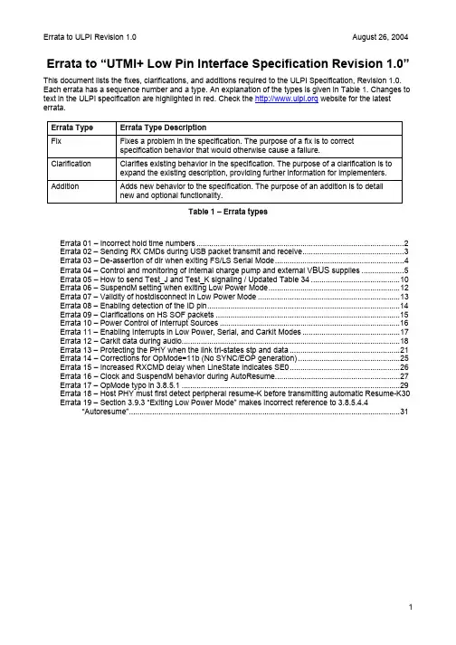
Errata to “UTMI+ Low Pin Interface Specification Revision 1.0” This document lists the fixes, clarifications, and additions required to the ULPI Specification, Revision 1.0. Each errata has a sequence number and a type. An explanation of the types is given in Table 1. Changes to text in the ULPI specification are highlighted in red. Check the website for the latest errata.Errata Type Errata Type DescriptionFix Fixes a problem in the specification. The purpose of a fix is to correctspecification behavior that would otherwise cause a failure.Clarification Clarifies existing behavior in the specification. The purpose of a clarification is toexpand the existing description, providing further information for implementers. Addition Adds new behavior to the specification. The purpose of an addition is to detailnew and optional functionality.Table 1 – Errata typesErrata 01 – Incorrect hold time numbers (2)Errata 02 – Sending RX CMDs during USB packet transmit and receive (3)Errata 03 – De-assertion of dir when exiting FS/LS Serial Mode (4)Errata 04 – Control and monitoring of internal charge pump and external V BUS supplies (5)Errata 05 – How to send Test_J and Test_K signaling / Updated Table 34 (10)Errata 06 – SuspendM setting when exiting Low Power Mode (12)Errata 07 – Validity of hostdisconnect in Low Power Mode (13)Errata 08 – Enabling detection of the ID pin (14)Errata 09 – Clarifications on HS SOF packets (15)Errata 10 – Power Control of Interrupt Sources (16)Errata 11 – Enabling Interrupts in Low Power, Serial, and Carkit Modes (17)Errata 12 – Carkit data during audio (18)Errata 13 – Protecting the PHY when the link tri-states stp and data (21)Errata 14 – Corrections for OpMode=11b (No SYNC/EOP generation) (25)Errata 15 – Increased RXCMD delay when LineState indicates SE0 (26)Errata 16 – Clock and SuspendM behavior during AutoResume (27)Errata 17 – OpMode typo in 3.8.5.1 (29)Errata 18 – Host PHY must first detect peripheral resume-K before transmitting automatic Resume-K30 Errata 19 – Section 3.9.3 “Exiting Low Power Mode” makes incorrect reference to 3.8.5.4.4 “Autoresume” (31)Errata 01 – Incorrect hold time numbersType:Fix.Issue:The hold time numbers given in Table 5 were calculated wrongly, and given the wrong polarity.Resolution:The correct numbers must be given in Table 5.Documentation Changes:Table 5 must be replaced with the table below to update the hold time numbers.UnitsMaxMinParameter SymbolOutput clockSetup time (control in, 8-bit data in) T SC, T SD 6.0 nsHold time (control in, 8-bit data in) T HC, T HD 0.0 nsOutput delay (control out, 8-bit data out) T DC, T DD9.0 nsnsSetup time (4-bit data in) (optional) T SDD 3.0Hold time (4-bit data in) (optional) T HDD-0.8 nsOutput delay (4-bit data out) (optional) T DDD 4.0nsInput clock (optional)Setup time (control in, 8-bit data in) T SC, T SD 3.0 nsHold time (control in, 8-bit data in) T HC, T HD 1.5 nsOutput delay (control out, 8-bit data out) T DC, T DD 6.0 nsnsSetup time (4-bit data in) T SDD 2.5Hold time (4-bit data in) T HDD0.8 nsnsOutput delay (4-bit data out) T DDD 3.5Table 5 – ULPI Interface TimingErrata 02 – Sending RX CMDs during USB packet transmit and receive Type:Clarification.Issue:It is not clear what the PHY should do when an RX CMD needs to be sent when the ULPI bus is carrying USB transmit or receive data.Resolution:An RX CMD should never abort USB transmit or receive data. Instead, the PHY must flag the RX CMD internally and send an RX CMD when nxt is de-asserted or when the receive packet has completed. Documentation Changes:For clarification on USB packet receive, the following text should be appended to the end of paragraph 1 in section 3.8.2.4.“All RX CMD changes during the USB packet receive must be signaled when nxt is low. If nxt is never low during the packet receive, all RX CMD changes must be replaced with a single RX CMD update that is sent at the end of the USB packet receive, when the ULPI bus is available. The RX CMD update must always convey the current RX CMD values, not a previous or old value.”Similarly, text in the USB packet transmit sections 3.8.2.1 and 3.8.2.2 should also be updated to reflect the text below.“All RX CMD changes during the USB packet transmit must be replaced with a single RX CMD update that is sent at the end of the USB transmit, when the ULPI bus is available. The RX CMD update must always convey the current RX CMD values, not a previous or old value.”Errata 03 – De-assertion of dir when exiting FS/LS Serial ModeType:Clarification.Issue:In section 3.10.3 “Exiting FsLsSerialMode”, the text describing the de-assertion of dir when exiting serial mode with the clock running is wrong, and does not match Figure 52. This also applies to exiting Carkit mode, where it is defined that “Entering and exiting Carkit mode is identical to Serial mode”. Resolution:The dir signal does not need to be de-asserted in the cycle after the link asserts stp to exit serial mode, but can be de-asserted 1 or more cycles after the link asserts stp.Documentation Changes:The second paragraph in section 3.10.3 should be replaced with the text below. Figure 53 should be replaced with the figure below.“If the clock is running, the Link signals the PHY to exit FsLsSerialMode by asserting stp. The PHY will de-assert dir1 or more cycles after it detects stp asserted, as shown in Figure 53. The Link de-asserts stp in the cycle following the de-assertion of dir. Like Low Power Mode, there is a single cycle of bus turnaround on data in the cycle following the de-assertion of dir. During the turnaround cycle, the value on data is not valid. The PHY stops driving the serial mode signals immediately before the turnaround cycle.”Errata 04 – Control and monitoring of internal charge pump and external V BUS suppliesType:Fix, clarification, and addition.Issue:Control of the internal V BUS charge pump or external V BUS supply causes an unnecessary burden on link hardware. Also, when the V BUS supply is external to the PHY, it is not clear how the Link is informed whenV BUS has an over-current condition.Resolution:This issue applies only to controllers with host capability.For control of the V BUS source, the definition of DrvVbus and DrvVbusExternal can be simplified, leading to a more practical link architecture.For monitoring an external V BUS supply, the external V BUS valid or fault indicator should be routed to an input pin on the PHY, replacing any internal V A_VBUS_VLD comparator. This removes the need for extra pins on the link and keeps all V BUS indicators in-band to the ULPI bus.Documentation Changes:This change effects the external pin descriptions, the OTG Operations section and the Immediate Register Set description.The following paragraphs and table should replace the paragraph titled DrvVbusExternal in section 3.3. The optional VbusValidExternal pin should also be shown on Figure 5.DrvVbusExternal and ExternalVbusIndicatorThe PHY may optionally control an external V BUS power source via the optional pin DrvVbusExternal. For example, the external supply could be a charge pump or 5V power supply controlled using a power switch. The external supply is controlled by the DrvVbus and the optional DrvVbusExternal bits in the OTG Control register. The polarity of the DrvVbusExternal output pin is implementation dependent.If control of an external V BUS source is provided the PHY may optionally provide for a V BUS power source feed back signal on the optional pin ExternalVbusIndicator. If this pin is provided, the use of the pin is defined by the optional control bits in the OTG Control and Interface Control registers. See Section 3.8.6.3 for further detail.The following text will be appended to section 3.8.6.Vbus Power Control (internal and external)The link turns on V BUS by setting the DrvVbus bit in the OTG Control Register. If the Vbus supply is external to the PHY, the link sets DrvVbus and the optional DrvVbusExternal bit in the OTG Control register. TheV BUS control settings are detailed in Table XX.DrvVbus DrvExternalVbus Power Source used0 X Internal and external V BUS power sources disabled.1 0V BUS charge pump enabled.Internal1 1 External 5V V BUS supply enabled.Table XX – OTG Control register power control bitsSection 3.8.6.3 will be replaced with the following text, table, and figure.Vbus Comparator ThresholdsIf the V BUS power supply is external to the PHY, and the external supply provides a signal indicating when V BUS is valid, it is recommended that this signal be an input to the PHY on an optional pin ExternalVbusIndicator, and that the state of that pin be reflected to the Link via the V A_VBUS_VLD ≤V BUS indication in the RX CMD byte. The optional UseExternalVbusIndicator bit in the OTG Control register selects between the internal and external VbusValid indicators.To support industry standard USB power control devices, the PHY may optionally support two additional bits in the Interface Control register, IndicatorPassThru and IndicatorComplement. These two bits allow the optional ExternalVbusIndicator pin to interoperate with either a power valid signal or an over-current fault output from the power control device, and to adapt to either active high or active low signals from the power control device. When a power fault signal is provided on the ExternalVbusIndicator pin, the PHY must use a logical combination of the output from the internal VbusValid comparator and the external power fault signal to generate the V A_VBUS_VLD ≤V BUS indication. Table YY defines the use of the UseExternalVbusIndicator, IndicatorPassThru and IndicatorComplement register bits to control the use of the ExternalVbusIndicator input pin and the internal VbusValid comparator output to generate theV A_VBUS_VLD ≤V BUS indication in the RX CMD byte. Table YY also indicates typical applications of each setting. Figure YY provides a graphical representation of the logical combination of the internal and external VbusValid sources, and how the control register bits effect the V A_VBUS_VLD ≤V BUS indication in the RX CMD byte. The UseExternalVbusIndicator, IndicatorPassThru and IndicatorComplement control register bits are individually optional. The PHY may implement any combination of the optional control bits, however, if the control bits are implemented they must provide the function defined in Table YY. If any of the control bits are not implemented it is the responsibility of the PHY to define how the optional ExternalVbusIndicator pin effects the state of the V A_VBUS_VLD ≤V BUS indication in the RX CMD byte.Typical Application UseExternalVbusIndicatorIndicatorPassThruIndicatorComplementRxCmd V BUS Valid source0 don’t care don’t care Internal V A_VBUS_VLD comparator.1 1 0 External active high V A_VBUS_VLD signal.1 1 1 External active low V A_VBUS_VLD_Nsignal.1 0 1 External active high power fault signalqualified with internal V A_VBUS_VLDcomparator.OTG Device1 0 0 External active low power fault signalqualified with internal V A_VBUS_VLDcomparator.1 1 0 External active high power fault signal. Standard Host1 1 1 External active low power fault signal.StandardPeripheral0 don’t care don’t care Internal V A_VBUS_VLD comparator.1Table YY – RxCmd V BUS Valid over-current conditions1 A standard peripheral should not use Vbus Valid to begin operation. The internal VbusValid may not indicate Vbus is valid on the 5th hub tier, which is allowed to be as low as 4.375V. Therefore the peripheral should use Session Valid.Figure YY – RxCmd V A_VBUS_VLD ≤V BUS indication sourceDepending on the application, the link should enable or disable the appropriate Vbus interrupts. Example settings for typical applications are given in Table ZZ.Application VbusValid2 SessValid SessEndStandard Host Yes No NoStandard Peripheral No Yes NoOTG A-Device Yes Yes NoOTG B-Device No Yes YesTable ZZ – Vbus indicators in the RXCMD required for typical applications2 The VbusValid indicator in the RXCMD comes from either the internal VbusValid comparator, or the external Vbus indicator input.A new register bit is defined in the OTG Control register replacing reserved bit 7 as follows:Field name Bit Access Reset DescriptionUseExternal VbusIndicator 7 rd/wr/s/c 0b Tells the PHY to use an external V BUS over-currentindicator. This bit is optional. Refer to 3.8.6.3.0b: Use the internal OTG comparator (V A_VBUS_VLD)or internal V BUS valid indicator (default).1b: Use external V BUS valid indicator signalTwo new register bits are defined in the Interface Control register replacing reserved bits 5 and 6 as follows:Field name Bit Access Reset Description IndicatorComplement 5 rd/wr/s/c 0b Tells the PHY to invert the ExternalVbusIndicatorinput signal, generating the Complement Output.Refer to 3.8.6.3 and Figure YY for more details.0b: PHY will not invert ExternalVbusIndicator signal(default).1b: PHY will invert ExternalVbusIndicator signal.IndicatorPassThru 6 rd/wr/s/c 0b Controls whether the Complement Output is qualifiedwith the Internal VbusValid comparator before beingused in the Vbus State in the RXCMD. Refer to 3.8.6.3and Figure YY for more details.0b: Complement Output signal is qualified with theInternal VbusValid comparator.1b: Complement Output signal is not qualified with theInternal VbusValid comparator.The DrvVbus and DrvVbusExternal are redefined in the OTG Control register as follows.Field name Bit Access Reset DescriptionDrvVbus 5 rd/wr/s/c 0b Signals the internal charge pump or external supply todrive 5V on Vbus.0b : do not drive Vbus(default).1b : drive 5V on VbusDrvVbusExternal 6 rd/wr/s/c 0b Selects between the internal and the external 5V Vbussupply. This bit is optional and does not need to bepresent if only one Vbus power source is supported.0b : Drive Vbus using the internal charge pump(default). Support of an internal charge pump isoptional.1b : Drive Vbus using external supply. Support of anexternal Vbus power source is optional.The following change will be made to the Vbus State bits in the RXCMD byte definition in 3.8.1.2.Encoded Vbus Voltage stateValue V BUS Voltage SessEnd SessValid VbusValid 300 V BUS < V B_SESS_END 1 0 0 01 V B_SESS_END ≤ V BUS < V SESS_VLD 0 0 0 10 V SESS_VLD ≤ V BUS < V A_VBUS_VLDX1 03:2 Vbus State11V A_VBUS_VLD ≤ V BUSX X 13The VbusValid indicator in the RXCMD comes from either the internal VbusValid comparator, or the external Vbusindicator input.Errata 05 – How to send Test_J and Test_K signaling / Updated Table 34Type:Clarification.Issue:It is not clear how a ULPI PHY can send Test_J and Test_K signaling, as required by USB section 7.1.20.Also, the contents of Table 34 (Signalling Modes) are difficult to read and are causing confusion for implementers.Resolution:For peripherals, Test_J and Test_K signalling is already detailed in UTMI section 5.16.1. The link controller places the PHY into HS mode, and disables bit stuffing and NRZI encoding. The link controller then transmits a constant stream of 1’s to generate the Test_J, or a constant stream of 0’s to generate the Test_K. The same applies to peripheral, host, and OTG devices.The contents of Table 34 should be clarified using groupings.Documentation Changes:The following changes should be made to Table 34 in section 4.4.Register SettingsResistor Settings Signalling modeX c v r S e l e c tT e r m S e l e c tO p M o d eD p P u l l d o w nD m P u l l d o w n r p u _d p _e nr p u _d m _e nr p d _d p _e nr p d _d m _e n h s t e r m _e nGeneral Settings Tristate DriversXXb Xb01b XbXb0b 0b 0b 0b 0b Power-up or Vbus < Vth(SESSEND ) 01b 0b 00b 1b 1b0b 0b 1b 1b 0bHost Settings Host Chirp 00b 0b 10b 1b 1b 0b 0b 1b 1b 1b Host Hi-Speed 00b 0b 00b 1b 1b 0b 0b 1b 1b 1b Host Full Speed X1b 1b 00b 1b 1b 0b 0b 1b 1b 0b Host HS/FS Suspend 01b 1b 00b 1b 1b 0b 0b 1b 1b 0b Host HS/FS Resume 01b 1b 10b 1b 1b 0b 0b 1b 1b 0b Host Low Speed10b 1b 00b 1b 1b 0b 0b 1b 1b 0b Host Low Speed Suspend 10b 1b 00b 1b 1b 0b 0b 1b 1b 0b Host Low Speed Resume 10b 1b 10b 1b 1b 0b 0b 1b 1b 0b Host Test_J/Test_K 00b 0b 10b 1b 1b0b 0b 1b 1b 1bPeripheral Settings Peripheral Chirp 00b 1b 10b 0b 0b 1b 0b 0b 0b 0b Peripheral Hi-Speed00b 0b 00b 0b 0b0b 0b 0b 0b 1bPeripheral Full Speed 01b 1b 00b 0b 0b1b 0b 0b 0b 0b Peripheral HS/FS Suspend 01b 1b 00b 0b 0b1b 0b 0b 0b 0b Peripheral HS/FS Resume 01b 1b 10b 0b 0b1b 0b 0b 0b 0b Peripheral Low Speed 10b 1b 00b 0b 0b0b 1b 0b 0b 0b Peripheral Low Speed Suspend 10b 1b 00b 0b 0b0b 1b 0b 0b 0b Peripheral Low Speed Resume 10b 1b 10b 0b 0b0b 1b 0b 0b 0b Peripheral Test_J/Test_K 00b 0b 10b 0b 0b0b 0b 0b 0b 1b OTG device, Peripheral Chirp 00b 1b 10b 0b 1b1b 0b 0b 1b 0b OTG device, Peripheral Hi-Speed 00b 0b 00b 0b 1b0b 0b 0b 1b 1b OTG device, Peripheral Full Speed 01b 1b 00b 0b 1b1b 0b 0b 1b 0b OTG device, Peripheral HS/FS Suspend 01b 1b 00b 0b 1b1b 0b 0b 1b 0b OTG device, Peripheral HS/FS Resume 01b 1b 10b 0b 1b1b 0b 0b 1b 0b OTG device, Peripheral Test_J/Test_K 00b 0b 10b 0b 1b0b 0b 0b 1b 1b Table 34 – Upstream and downstream signaling modesErrata 06 – SuspendM setting when exiting Low Power ModeType:Clarification.Issue:In section 3.9.3, Figure 46 and Figure 47, of the ULPI specification, it is not clear if it is the responsibility of the link or the PHY to set the SuspendM register bit to a 1 after exiting Low Power Mode. Unless a clear responsibility is stated, both link and PHY might assume that the other sets SuspendM to 1b, resulting in a hung bus that is always in Low Power Mode.Resolution:This is clarified in the SuspendM definition in Table 19, which states “The PHY must automatically set this bit to ‘1’ when Low Power Mode is exited.”To make this even clearer to the reader, a clarification should be added to section 3.9.3. Documentation Changes:The following changes will be added to the first paragraph of section 3.9.3.“As shown in Figure 46 and Figure 47, the Link signals the PHY to exit Low Power Mode by asynchronously asserting stp. The PHY immediately starts to wake up its internal circuitry. When the PHY clock meets ULPI timing requirements, the PHY de-asserts dir. The PHY must ensure a minimum of 5 cycles of clock have been driven prior to de-asserting dir. The PHY must also ensure that the SuspendM register is automatically set to 1b prior to de-asserting dir. The Link de-asserts stp in the cycle following the de-assertion of dir. There is one cycle of data bus turnaround provided after the de-assertion of dir, during which the value on data is not valid. The PHY stops driving the signals of Table 12 immediately before the turnaround cycle.”Figure 46 will also be changed to reflect that the SuspendM register bit must be set to 1b prior to de-asserting dir.Errata 07 – Validity of hostdisconnect in Low Power ModeType:Clarification.Issue:It is not clear if hostdisconnect is valid when the PHY is acting as a host and Low Power Mode is enabled. Resolution:This is clarified in the UTMI+ specification, but should be indicated in ULPI for clarity. The hostdisconnect status signal must be reset to 0b when the PHY enters Low Power Mode. Since the disconnect detection circuitry is powered down in Low Power Mode, no detection is possible. The link must look at LineState on the data bus for connect and disconnect events.Documentation Changes:The hostdisconnect description in Table 24 already states that “Applicable only in host mode”. This text must be expanded to state that:“Applicable only in host mode. Automatically reset to 0b when Low Power Mode is entered.”Errata 08 – Enabling detection of the ID pinType:Clarification.Issue:It is not clear when the IdGnd status is valid.Resolution:This is clarified in the UTMI+ specification, but should also be clarified in ULPI. The IdGnd status is valid50ms after IdPullup is set to 1b, and the OTG state machines should sample IdGnd only after the 50ms time. Documentation Changes:The IdGnd definition in Tables 22, 23, 24, and 25 require the following extra text:“IdGnd is valid 50ms after IdPullup is set to 1b, otherwise IdGnd is undefined and should be ignored.”Errata 09 – Clarifications on HS SOF packetsType:Clarification.Issue:HS SOF packets are not mentioned in the specification. This can cause confusion and could lead to implementations with different behaviors.Resolution:There are two important items to mention. First, the PHY must automatically append a 40-bit EOP when executing a TX CMD with the PID field set to A5. Second, HS SOF packets have a larger TX End Delay. Documentation Changes:The following text will be added to section 3.8.2.2:"For all PID packets, the PHY must automatically prepend a SYNC pattern and append an EOP pattern. In High Speed, when the PID field of the TX CMD is 5h, the PHY must recognize that this is a Start-Of-Frame (SOF) packet and automatically append a long EOP."A new row will be added to Table 9 to expand the TX End Delay parameters, as shown below.TX End Delay2-5 N/A N/ANumber of clocks between the PHY detecting stp on theULPI bus to completing transmission of EOP on the USBbus. Used for HS packets only. The Link can use TX EndDelay to calculate when the packet has completedtransmitting on the USB.HS EOP is completed when all 8 consecutive 1’s havefinished transmitting on the USB bus.FS and LS packets finish many clock cycles after stp isasserted. The Link must look for RX CMD bytes indicatingSE0-to-J transition to determine when the transmission hascompleted on the USB bus.6-9 N/A N/A HS SOF packets have a long EOP. The link must wait atleast 9 clocks or for an RX CMD indicating squelch(LineState = 00b) before transmitting the next packet.Errata 10 – Power Control of Interrupt SourcesType:Clarification.Issue:It is not known which interrupts should be powered down in each mode.Resolution:To ensure multi-vendor interoperability, the link must control the power state of the interrupts. Whenever an interrupt rising/falling enable bit is set, the associated circuit must be powered, regardless of the mode. There are two exceptions:1. IdGnd is gated with IdPullup.2. Hostdisconnect is never valid during Low Power Mode.Documentation Changes:The following text will be added to the first paragraph of Section 3.6, Interrupt Event Notification.“If an interrupt is enabled, the PHY must power the needed circuitry regardless of which mode the PHY is in. The only exceptions are the HostDisconnect interrupt which is valid only in Synchronous Mode, and the IdGnd interrupt which is controlled by IdPullup.”The following change will be made to the first paragraph of Section 3.9, Low Power Mode.“The Link can optionally place the PHY into Low Power Mode when the USB bus is suspended. The PHY can power down all circuitry except the interface pins and full speed receiver. The bus resistors must also be powered if V BUS is present. Any function must be powered if its corresponding register bit is set, including interrupt sources and the charge pump. If the PLL is powered down, the clock must be stopped without glitches.”The following change will be made to the first paragraph of Section 3.10, Full Speed / Low Speed Serial Mode.“Full Speed / Low Speed Serial Mode (FsLsSerialMode) gives the Link direct access to the FS/LS serial analog transmitter and receiver. Two types of serial mode are defined in ULPI: 3-pin FsLsSerialMode, and 6-pin FsLsSerialMode. Both modes are optional. The PHY can power down all circuitry except the interface pins, full speed transmitter and receiver. Any function must be powered if its corresponding register bit is set, including interrupt sources and the charge pump.”The following line will be added to the text describing interrupt registers in sections 4.2.5, 4.2.6, 4.2.7, and 4.2.8.“Interrupt circuitry can be powered down in any mode when both rising and falling edge enables are disabled.”Errata 11 – Enabling Interrupts in Low Power, Serial, and Carkit Modes Type:Clarification.Issue:It is not known if both rising and falling edges should be enabled when the clock is powered down. Resolution:A clarification will be added that the link/software should set both the rising and falling interrupt enables whenever entering a mode where clock is off, such as Low Power Mode and Serial Mode. Documentation Changes:The following line will be added to the text describing interrupt registers in sections 3.6, 4.2.5, 4.2.6, 4.2.7, and 4.2.8.“To ensure interrupts are detectable when clock is powered down, the link should enable both rising and falling edges.”Errata 12 – Carkit data during audioType:Addition.Issue:The carkit specification was not complete at the time of releasing ULPI 1.0. New additions are required to the ULPI register set to comply with the latest carkit specification. Specifically, carkit has added a data during audio feature.Resolution:Four new registers at a total of 6 addresses are required in the reserved area of the ULPI register set to provide the data during audio feature.Documentation Changes:The following text will be added to Section 3.11, Carkit.In cases of conflict between this specification and the Carkit specification, the Carkit specification shall take precedence.Four new registers are defined in Table 16, replacing 6 of the reserved addresses.Address (6 bits)Field nameSize (bits) Rd Wr Set Clr Immediate Register SetCarkit Pulse Control (Optional) 8 22-24h 22h 23h 24h Transmit Positive Width (Optional) 8 25h 25h - - Transmit Negative Width (Optional) 8 26h 26h - - Receive Polarity Recovery (Optional)8 27h 27h - -Register details will be inserted after section 4.2.15 as follows:4.2.16 Carkit Pulse ControlAddress: 22h-24h (Read), 22h (Write), 23h (Set), 24h (Clear).This register is optional. It controls the operation of the carkit data-during-audio function within the PHY. The TxPlsEn and RxPlsEn bits are ignored if the CarkitMode bit in the Interface Control register is not set.Refer to [Ref 7] for more information on carkit.Field name Bits Access Reset Description TxPlsEn 0rd/wr/s/c0bEnables data-during-audio pulse transmitRxPlsEn 1 rd/wr/s/c 0b Enables data-during-audio pulse receive SpkrLeftBiasEn 2 rd/wr/s/c 0b Enables bias for left speaker. SpkrRightBiasEn3rd/wr/s/c0bEnables bias for right speaker.Reserved 7:4 - 0000b Reserved.Table 2 – Carkit Pulse ControlTxPlsEnWhen the TxPlsEn bit is set, and the SpkLeftEn bit in the Carkit Control register is set, then the PHY shall output a positive pulse followed by a negative pulse on the D- line after each rising or falling edge on the data(0) line. When generating such a pulse pair, the PHY shall perform the steps, as defined in the Carkit specification [Ref 7]. The following list of steps provides information on the intent of the Carkit specification.• tri-state the speaker buffer that drives the D- line• drive the D- line to a voltage of 3.3V +/- 10%• wait for the time specified in the Transmit Positive Width register• drive the D- line to ground• wait for the time specified in the Transmit Negative Width register• stop driving the D- line to ground• enable the speaker buffer that drives the D- lineRxPlsEnWhen the RxPlsEn bit is set, and the MicEn bit in the Carkit Control register is set, then the PHY shall toggle the data(1) output each time a falling edge is detected on the D+ line that crosses the carkit interrupt threshold of V PH_DP_LO. When the RxPlsEn bit is set, the Receive Polarity Recovery timer shall be enabled.4.2.17 Transmit Positive WidthAddress: 25h (Read), 25h (Write)This register is optional. It specifies the width of the positive pulse that is output on the D- line when the TxPlsEn bit is set. The time is measured in units of 60MHz clock periods. The minimum TxPosWdth that must be supported is 8. The maximum TxPosWdth that must be supported is 64.Refer to [Ref 7] for more information on carkit.Field name Bits Access Reset DescriptionTxPosWdth 7:0 rd/wr 10h Transmit positive pulse widthTable 3 – Transmit Positive Width4.2.18 Transmit Negative WidthAddress: 26h (Read), 26h (Write)This register is optional. It specifies the width of the negative pulse that is output on the D- line when the TxPlsEn bit is set. The time is measured in units of 60MHz clock periods. The minimum TxNegWdth that must be supported is 8. The maximum TxNegWdth that must be supported is 64.Refer to [Ref 7] for more information on carkit.Field name Bits Access Reset DescriptionTxNegWdth 7:0 rd/wr 20h Transmit negative pulse widthTable 4 – Transmit Negative Width4.2.19 Receive Polarity RecoveryAddress: 27h (Read), 27h (Write)This register is optional.When the data-during-audio feature is enabled in the Carkit [Ref 7], then the carkit sends UART data to the phone by converting the non-return-to-zero (NRZ) UART signal into a series of pulses, and transmitting。
XS1-L Hardware Design ChecklistDocument Revision1.3Publication Date: 2011/06/06Copyright©2011XMOS Limited,All Rights Reserved.1IntroductionThis document is intended for use by hardware designers using the XMOS XS1-L family of devices.It is a checklist of items that should be included in all XS1-L designs to ensure correct operation.For further details refer to the relevant device datasheet. 2ChecklistEach of the following sections contains items to check for each design using an XS1-L series device.2.1Ground PadThe centre ground pad for all XS1-L packages is the main device ground and must be connected to circuit ground.Multiple vias should be used from the centre pad to the circuit ground plane to minimise impedance and conduct heat away from the device.2.2Power supply sequencingThe VDDIO(and OTP_VDDIO if present)supply must be within specification(3.0V-3.6V)before the VDD(core)supply is turned on.Specifically,the VDDIO supplies should be within specification before VDD core reaches0.4V.2.3VDD ramp rateThe VDD(core)supply should ramp monotonically(constantly rising)from0V to its final value(0.95V-1.05V)within10ms to ensure correct startup.2.4VDD(core)supply capabilityThe VDD(core)supply should be capable of supplying at least300mA for an L1and 600mA for an L2device assuming they may be operating at full capacity.2.5Power supply decouplingEnsure the design has multiple decoupling capacitors per supply placed close to the relevant supply pins.An example would be a minimum of4x0402or0603size surface mount capacitors of100nF in value,per supply.The ground side of the decoupling capacitors should have as short a path back to the ground pins of the device(mainly the centre pad)as possible.A bulk decoupling capacitor of at least 10uF should be placed on each supply.2.6PLL_AVDDA low passfilter is highly recommended on this pin to avoid noise affecting the internal PLL.An RCfilter is used on the XMOS reference designs with a1uF or100nF ceramic capacitor and a4.7R(L1)or2.2R(L2)resistor.Thefilter(and especially the capacitor)should be placed close to the PLL_AVDD pin.2.7Power on resetThe RST_N and TRST_N pins must be asserted(low)during or after power up.The device should not be used until these resets have taken place.As the errata in the datasheets show,the internal pullups on these two pins can occasionally provide stronger than normal pullup currents.For this reason,an RC type reset circuit is discouraged as behaviour would be unpredictable.A voltage supervisor type reset device is recommended to guarantee a good reset.This also has the benefit of resetting the system should the relevant supply go out of specification.2.8Clock inputThe CLK input pin should be supplied with a clock with monotonic rising edges and low jitter levels.Note that the PCU_CLK pin(only on some packages)must also be supplied with a clock for the device to function correctly,even if the PCU is not being used.The main CLK input can be tied to the PCU_CLK input to satisfy this condition.2.9SPI bootIf booting the device from a SPI Flash,ensure the MODE pins are set correctly(MODE3 =1,MODE2=1)and that the SPI Flash is connected to the correct ports as shown below:Pin Name SPI Signal DescriptionX0D0MISO Data-Master In Slave OutX0D1SS Slave SelectX0D10SCLK ClockX0D11MOSI Data-Master Out Slave InIf code debug via JTAG is required(e.g.code development)then make sure the MODE pins are set to boot from JTAG(i.e.don’t boot anything,wait to have code loaded over JTAG).This condition requires MODE3=0,MODE2=0and can be set with a jumper or similar.2.10USB ULPI ModeThe XS1-L1contains support for connecting to a USB transceiver using the UTMI+ Low Pin Interface(ULPI).When using the XS1-L1with ULPI,the ULPI signals must only be connected to specific ports as shown in the following table.When using ULPI,some ports on the same core are used internally and so are not available for use by user software.These are shown greyed out in the table.The available ports are shown in green.All ports on other cores are unaffected.Note that this limitation only applies when the ULPI is enabled,the greyed out ports can still be used before or after the ULPI is being used.2.11USB ULPI Port Table3Device ConfigurationExample XS1-L designs including schematics and layouts can be found on the XMOS website at:/support/silicon4Related DocumentsInformation about XMOS technology is primarily available from the XMOS website; please see /documentation for the latest documents or click on one of the links below tofind out more information.Document Document referenceXS1-L148TQFP Datasheet xs1-l1-48tqfp-datasheetXS1-L164LQFP Datasheet xs1-l1-64lqfp-datasheetXS1-L1128TQFP Datasheet xs1-l1-128tqfp-datasheetXS1-L2124QFN Datasheet xs1-l2-124qfn-datasheetXS1-L System Specification xsystemlXS1-L Clock Frequency Control Application Note xs1l_clkXS1Port I/O Timing Application Note xs1_port_timingXS1-L Link Performance and Design Guidelines xs1l_linksEstimating Power Consumption For XS1-L Devices xs1l_powerDevice Package User Guide package_user_guide5Document HistoryDate Release Comment2010-04-20 1.0First release2010-04-22 1.1Added ULPI interface information2011-04-26 1.2Added XS1-L1-48TQFP&Device Package User Guide Links 2011-06-06 1.3Added ground pad requirementsCopyright©2011XMOS Limited,All Rights Reserved.XMOS Limited is the owner or licensee of this design,code,or Information(collectively,the“Information”) and is providing it to you“AS IS”with no warranty of any kind,express or implied and shall have no liability in relation to its use.XMOS Limited makes no representation that the Information,or any particular implementation thereof,is or will be free from any claims of infringement and again,shall have no liability in relation to any such claims.XMOS and the XMOS logo are registered trademarks of XMOS Limited in the United Kingdom and other countries,and may not be used without written permission.All other trademarks are property of their respective owners.Where those designations appear in this book,and XMOS was aware of a trademark claim,the designations have been printed with initial capital letters or in all capitals.。
天然奇观新西兰的蒂阿纳努伊新西兰,这个拥有绝美风光的南太平洋岛国,以其壮丽的自然景观而闻名于世。
在这片土地上,有着无数令人叹为观止的天然奇观,其中之一就是蒂阿纳努伊(Te Anau)- 一个让人心醉神迷的地方,也是追寻自然魅力的绝佳去处。
蒂阿纳努伊位于新西兰南岛西南部,是世界上最大的地下湖系统之一。
它以其独特而壮观的地貌景观而闻名,被誉为“堕落在天空中的天堂”。
在蒂阿纳努伊之旅中,你将有幸探索马洛昆(Milford Sound)和邦尼威尔(Doubtful Sound),这是这一地区最知名的湖泊。
马洛昆是最著名的景点之一,被列为世界文化遗产。
湖泊周围高耸的山峦、壮丽的瀑布和蓝绿色的湖水构成了一幅美不胜收的画面。
在邦尼威尔,你可以感受到被大自然所包围的宁静,仿佛回到了世界的起源。
除了湖泊和山脉之外,蒂阿纳努伊还拥有令人惊叹的地下洞穴网络。
蓝色洞穴是蒂阿纳努伊最独特的地下奇观之一。
当阳光透过洞穴顶部的水面照射下来时,洞穴内的水变成了令人难以置信的蓝色,美得几乎令人窒息。
这是一场绝妙的视觉盛宴,让人流连忘返。
在蒂阿纳努伊的旅程中,你还可以参观开普林(Kepler Track)和密尔福德小径(Milford Track)等著名的徒步旅行路线。
这些路线穿越了壮丽的山谷、森林和草地,让你有机会近距离欣赏到新西兰独特的植被和野生动物。
无论你是冒险爱好者还是自然爱好者,这里的自然美景都能满足你的所有期待。
除此之外,蒂阿纳努伊还有丰富多样的动植物世界。
在这个地区,你可以看到各种各样的鸟类,包括几种独特的几维鸟(Kiwi)和信天翁。
在湖水中,你还可以看到一些罕见的淡水鱼类,其中最著名的是恐龙鱼(Paua)和翡翠鱼(Kōkopu)。
这些独特的物种丰富了这片土地的生态系统,并使之成为一个令人惊叹的动植物乐园。
综上所述,蒂阿纳努伊无疑是一个天然奇观的宝库。
无论你是想远足徒步,还是想近距离感受大自然的美丽,这个地方都不会让你失望。
DESIGNWARE IP数据手册/designware 简介借助DesignWare® 嵌入式USB 2.0 (eUSB2) PHY、eUSB2中继器、USB数字控制器、验证IP和IP子系统方面的专业知识,新思科技为设计人员提供了适用于低功耗移动和消费类产品的USB 2.0 IP解决方案,例如采用业界最先进工艺节点设计的智能手机、平板电脑、笔记本电脑、游戏和 AR/VR,以及无线设备。
USB Type-C“Chip to World”“Chip to World”图1:eUSB2用例业内最先进的工艺节点不支持USB 2.0规范要求的3.3V信号和5V容限。
3.3V 信号最初在1994年的USB 1.0规范中定义,需要向后兼容。
eUSB2 规范为低功耗芯片间通信定义了新的更低电压的USB信号。
eUSB2中继器在标准USB 2.0和eUSB2信号电平之间转换,允许旧有USB 2.0设备与配有eUSB2 PHY的片上系统 (SoC) 连接。
DesignWare USB IP的设计依托客户多年来使用新思科技通过硅晶验证的USB PHY产品线取得的成功,而且该产品线已移植到180nm 到 5nm 的100多个工艺节点中。
通过与DesignWare主机、设备或双角色数字控制器结合使用,并使用新思科技的验证IP进行验证,DesignWare eUSB2 IP可为高级SoC设计提供完整的USB 2.0解决方案。
要点• 符合eUSB2 1.1规范• 可用于USB主机、设备和双角色应用中• eUSB2 PHY和eUSB2中继器支持 USB2.0 480Mbps(高速)、12Mbps(全速)和 1.5Mbps(低速)数据速率• eUSB2 PHY专为不支持3.3V信号和5V容限的最先进工艺节点而设计• eUSB2 PHY接口:UTMI+ 3级规范• eUSB2中继器专为支持3.3V信号和5V容限的成熟工艺节点而设计目标应用• 智能手机• 平板电脑• 轻薄型 PC 和混合型 PC• 笔记本和台式电脑• 游戏、AR/VR• 高级无线设备(5G调制解调器、WiFi 6)技术• eUSB2 PHY: 5nm, 7nm• USB2中继器:28nm eUSB2 IP解决方案eUSB2 PHY IP特性• 专为高级工艺节点(7nm及以下)设计• 最大限度地减少由于工艺、电压、温度、封装和板卡寄生参数的变化而产生的影响• 支持USB 2.0 480Mbps(高速)、12Mbps(全速)和1.5Mbps(低速)数据速率• 与新思科技的DesignWare USB 2.0、3.0、3.1和3.2主机、设备及双角色控制器连接• 最低功耗:对于用于eUSB2 芯片间通信的高级移动设备,可延长电池寿命Transceiver Common图2:eUSB2 PHY框图eUSB2中继器IP特性• 在eUSB2和USB 2.0信号电平间转换,使配有eUSB2 PHY的SoC能够与旧有USB 2.0产品连接• 专为成熟工艺节点而设计• 可集成到PMIC、音频、Wi-Fi、组合式无线芯片中,或作为独立(多端口)中继器芯片实施• 支持USB 2.0 480Mbps(高速)、12Mbps(全速)和1.5Mbps(低速)数据速率• 高级内置自检 (BIST)、可调性和诊断图3:eUSB2中继器框图2USB控制器IP特性• DesignWare USB 2.0、3.0、3.1和3.2数字控制器与DesignWare eUSB2 PHY兼容验证IP特性• 支持USB 3.2、3.1、3.0、2.0和 eUSB2• 100%原生SystemVerilog• 主机、设备和集线器仿真• 内置覆盖和验证计划• 全面的回调、消息处理和错误注入• 与Verdi Protocol Analyzer 3集成• 协议层–控制、中断和ISOC–数据突发–SuperSpeed批量数据流–LMP、SOF和ITP生成• 链路层–具有完全控制权的L TSSM可在任何状态启动–SuperSpeed电源管理–电缆连接和断开–速度增大和减小–测试模式• PHY层–SuperSpeed PIPE,与时钟恢复同步–USB 2.0 UTMI、ULPI接口IP子系统专业知识特性• 通过新思科技IP协议和SoC设计专家根据独特的SoC要求而配置和定制USB子系统,满足严格的项目进度要求• 通过专门针对SoC集成的子系统和验证测试,最大限度地减少子系统集成工作量同时使设计人员能够专注于发挥关键技能• 降低总体开发成本,©2021 Synopsys, Inc. All rights reserved. Synopsys is a trademark of Synopsys, Inc. in the United States and other countries. A list of Synopsys trademarksis available at /copyright.html . All other names mentioned herein are trademarks or registered trademarks of their respective owners.08/31/21.CS743817698 eUSB2 DS simplified chinese.。
带 ULPI 接口的 USB 2.0 高速 OTG 收发器特性▪符合 USB 2.0 修订版 1.3 的 OTG 补码和 ULPI 修订版 1.1▪支持 480 Mbps、12 Mbps 和 1.5 Mbps USB2.0 速度-集成终端电阻,满足 USB2.0 电阻 ECN-集成串行器和解串器-根据需要插入和删除填充位-USB 时钟与数据恢复可达±150pp▪支持USB OTG修订版1.3主机协商协议(HNP)和会话申请协议(SRP)▪15 kV ESD,IEC 61000 电路板级,空气间隙应用▪机顶盒视频照相机, MP3播放器▪移动电话,数字照相机,PDA▪DVD录像机, 扫描仪,打印机说明FUSB2805是UTMI+低引脚接口(ULPI) USB2.0 OTG收发器。
它符合通用串行总线规格修订版 2.0 (USB 2.0)、ULPI 规范修订版 1.1 和 USB 2.0 修订版 1.3 On-The-Go (OTG) 附录的规定。
FUSB2805 可通过 ULPI 链接器将 USB2.0 主机、外设或OTG 控制器连接到 USB 连接器进行优化。
可通过 12 位(SDR) 接口以高速 (480Mbps)、全速 (12Mbps) 和低速(1.5 Mbps) 三种速率传输和接收数据。
相关资源UTMI+ 低引脚接口规范 (ULPI) 修订版 1.1,2004 年 10 月 20 日。
UTMI+ 规范修订版 1.0,2004 年 2 月 22 日。
如果您需要更多的性能信息,请联系analogswitch@。
订购信息器件编号顶标工作温度范围封装FUSB2805MLX FUSB2805 -40 至+85°C 32 端子模塑无铅封装 (MLP),四通道,JEDEC MO-220FUSB2805 — 带 ULPI 接口的 USB 2.0 高速 OTG 收发器图1. 功能框图引脚布局Reg ister M apUS B D ata D eserializerTerm inatio n Resisto rsFreq uency S electP LLV o ltag e Reg ulato rP o wer-On ResetGlo b al Clo cksP ORID D etecto rOTG M o d uleE xternal V B US &Fault D etectio n Co ntro l B lo ck A nalo g Ref erence M o d uleS TP NX T CHIP _S E LE CT_NCFG1CLK IN V IOV CC3V 3V CC1V 2V CC 0.1µF4.7µF0.1µF4.7µFD MIDV B USV R E FReset_NFA ULTRRE FP S W100kIC (Flo at)Test (Flo at)400k50kID _P ULLUPV D D 3V 30.1µFGNDExposed DiePad12345D1D0VIO DM RREF 2423222120D 2C H I P _S E L E C T _ND 3V I OC G F 1C L O C KD 4D 53231252627282930D6D7NXTSTP VIOFUSB2805 — 带 ULPI 接口的 USB 2.0 高速 OTG 收发器DM AI/O USB D-引脚。
用于高速USB收发器的ULPI接口规范公布
佚名
【期刊名称】《《世界电子元器件》》
【年(卷),期】2005(000)009
【摘要】ULPI工作组日前宣布,首个用于高速通用串行总线(USB)和便携式USB(USB On-the-Go,OTG)收发器芯片的UTMI+低引脚数接LI(ULPI)行业规范已经公开发行。
专用集成电路(ASIC)、系统级芯片(SoC)及现场可编
程门阵列(FPGA)设计人员可通过该规范开发符合业界标准的接口,将现成的高速USB收发器整合剑他们的设计中。
这样就节省了设计开发时间,简化了验证和
产品测试过稃,还能保证嵌入式USB核心逻辑器件与高速USB收发器的互联互通。
【总页数】1页(P16)
【正文语种】中文
【中图分类】TP336
【相关文献】
1.用于独立高速USB收发器的ULPI接口规范公开发行 [J],
B333x/334x:ULPI收发器系列 [J],
3.TRANSDIMENSION与SMSC合作推出ULPI控制器和收发器获得USB-IF认证[J],
4.已获USB-IF认证的ULPI控制器和收发器 [J],
5.ULPI高速USB收发器 [J],
因版权原因,仅展示原文概要,查看原文内容请购买。
From:
1. UTMI USB
2.0 Transceiver Macrocell Interace
defines an interface between two IP blocks: the USB Tran sceiver Macrocell (IP) and the USB Link layer (SIE). The UTM I interface provides functionality for USB peripherals only, not f or USB hosts or On-The-Go.
2. UTMI+
adds host and On-The-Go capabilities to the USB system.
UTMI+ incrementally adds new functionality and interface si gnals to the Link and PHY.
UL PI: UTMI+ Low
3. ULPI: UTMI+ Low Pin Interface
The ULPI specification reduces the Link to PHY interface t o 12 or 8 signals, with support for all the features needed by
USB peripherals, hosts, and OTG. The result is a package si ze as small as 32 pins or less, compared with 64 to 80 pins for UTMI+.
4. ULPI PHY Register Set
There are four main types of registers:
ID Registers These registers provide a unique identifier to the USB system. If necessary,system software can change b ehavior based on different PHY attachment. This is not genera lly needed because PHY capabilities are chosen at hardware design time.
Mode Registers These registers control how the PHY beh aves. Many signals from UTMI+ are changed only when the U SB is idle, so they are placed in registers that are accessed only when the ULPI bus is idle. Several new features have al so been introduced, including Carkit Mode.
Interrupt Registers These registers inform the Link of stat us changes in the PHY. Many signals in UTMI+ convey inform ation to the Link that is not timing critical. Those signals have been replaced with status bytes and interrupt signaling. Statu s information is sent only when the ULPI bus is idle.
Extra Registers Additional register space is provided for t wo reasons. Some addresses have been reserved for future u se, while other registers are available for vendorspecific use.。