Rabi oscillations, Ramsey fringes and spin echoes in an electrical circuit
- 格式:pdf
- 大小:321.23 KB
- 文档页数:8
布宜诺斯艾利斯的特色食物英文作文Buenos Aires, the capital of Argentina, is known for its vibrant culture, rich history, and delicious cuisine. The city is a melting pot of flavors, influenced by its diverse immigrant population and local traditions. When it comes to food, Buenos Aires offers a wide range of options, from traditional Argentinean dishes to fusion cuisine with a modern twist. In this essay, we will explore some of the unique and delicious foods that make Buenos Aires a food lover's paradise.One of the most iconic dishes in Buenos Aires is the Argentine steak, or "asado." Asado is a traditional barbecue that typically features several cuts of meat, such as beef ribs, chorizo, and blood sausages, cooked over an open flame. The meat is seasoned with chimichurri sauce, a tangy herb sauce made from parsley, garlic, vinegar, and olive oil. Asado is more than just a meal in Buenos Aires – it is a social event that brings friends and family together to enjoy good food and conversation.Empanadas are another popular food in Buenos Aires, and they can be found in nearly every corner of the city. Empanadas are pastries filled with a variety of ingredients, such as beef, chicken, cheese, or vegetables, and then baked or fried until golden brown. These savory treats are perfect for a quick snackor a light meal on the go. Empanadas can be enjoyed at local cafes, food trucks, or even at traditional empanada shops known as "empanaderias."If you have a sweet tooth, Buenos Aires has plenty of options to satisfy your cravings. Dulce de leche is a popular sweet spread made from caramelized milk and sugar, and it is used in a variety of desserts, such as alfajores, a type of sandwich cookie filled with dulce de leche and coated in chocolate or powdered sugar. Another popular dessert in Buenos Aires is helado, or Argentine ice cream, which is known for its creamy texture and bold flavors. From traditional flavors like dulce de leche and chocolate to more unique options like mate or malbec wine, helado is a must-try treat in Buenos Aires.In addition to traditional Argentinean dishes, Buenos Aires also offers a variety of international cuisines influenced by its immigrant communities. For example, Italian immigrants brought their culinary traditions to Buenos Aires, leading to the popularity of dishes like pizza and pasta in the city. Japanese and Peruvian immigrants have also made their mark on Buenos Aires food scene, contributing to the rise of sushi and ceviche restaurants in the city. These fusion cuisines showcase thediversity of flavors and ingredients that can be found in Buenos Aires.Overall, Buenos Aires is a food lover's paradise, with a rich culinary heritage that combines traditional Argentinean dishes with international flavors. Whether you are craving a juicy steak, a savory empanada, or a sweet dulce de leche treat, Buenos Aires has something for every palate. So, if you find yourself in the "Paris of South America," be sure to indulge in the city's delicious and diverse cuisine – you won't be disappointed.。

北极冻土层英文阅读理解The Arctic tundra, a vast expanse of frozen soil, holds secrets that have been frozen in time for centuries. With layers of permafrost extending deep beneath the surface,it's a natural freezer for ancient remains and organisms.Exploring the tundra feels like stepping into a world untouched by modern civilization. The cold air bites at your nose, and the quiet is so absolute, you can almost hear the earth breathe. Beneath the snow and ice, there's a story that's slowly being revealed to us.The frozen soil acts as a time capsule, preserving things that have been lost to the rest of the world. From ancient mammals to mysterious microbes, the tundra is a treasure trove for scientists. But as the climate warms, these fragile ecosystems are under threat.Walking across the tundra, you can see evidence of how the environment is changing. Pools of meltwater form whereonce there was solid ice. Plants are beginning to grow in areas that were once barren. It's a reminder of thefragility of our planet and the need to protect these unique habitats.And yet, there's beauty in this desolate landscape. The stark contrast between the white snow and the blue sky is breathtaking. The silence is deafening, yet it's a silence that feels cleansing and pure. In the Arctic tundra, nature is at its most raw and unforgiving, yet it's also its most captivating.。
More informationPhase Noise and Frequency Stability in OscillatorsPresenting a comprehensive account of oscillator phase noise and frequency stability,this practical text is both mathematically rigorous and accessible.An in-depth treatmentof the noise mechanism is given,describing the oscillator as a physical system,andshowing that simple general laws govern the stability of a large variety of oscillatorsdiffering in technology and frequency range.Inevitably,special attention is given to am-plifiers,resonators,delay lines,feedback,andflicker(1/f)noise.The reverse engineeringof oscillators based on phase-noise spectra is also covered,and end-of-chapter exercisesare given.Uniquely,numerous practical examples are presented,including case studiestaken from laboratory prototypes and commercial oscillators,which allow the oscillatorinternal design to be understood by analyzing its phase-noise spectrum.Based on tuto-rials given by the author at the Jet Propulsion Laboratory,international IEEE meetings,and in industry,this is a useful reference for academic researchers,industry practitioners,and graduate students in RF engineering and communications engineering.Additional materials are available via /rubiola.Enrico Rubiola is a Senior Scientist at the CNRS FEMTO-ST Institute and a Professorat the Universit´e de Franche Comt´e.With previous positions as a Professor at theUniversit´e Henri Poincar´e,Nancy,and in Italy at the University Parma and thePolitecnico di Torino,he has also consulted at the NASA/Caltech Jet PropulsionLaboratory.His research interests include low-noise oscillators,phase/frequency-noisemetrology,frequency synthesis,atomic frequency standards,radio-navigation systems,precision electronics from dc to microwaves,optics and gravitation.More informationThe Cambridge RF and Microwave Engineering SeriesSeries EditorSteve C.CrippsPeter Aaen,Jaime Pl´a and John Wood,Modeling and Characterization of RF andMicrowave Power FETsEnrico Rubiola,Phase Noise and Frequency Stability in OscillatorsDominique Schreurs,M´a irt´ın O’Droma,Anthony A.Goacher and Michael Gadringer,RF Amplifier Behavioral ModelingFan Y ang and Y ahya Rahmat-Samii,Electromagnetic Band Gap Structures in AntennaEngineeringForthcoming:Sorin V oinigescu and Timothy Dickson,High-Frequency Integrated CircuitsDebabani Choudhury,Millimeter W aves for Commercial ApplicationsJ.Stephenson Kenney,RF Power Amplifier Design and LinearizationDavid B.Leeson,Microwave Systems and EngineeringStepan Lucyszyn,Advanced RF MEMSEarl McCune,Practical Digital Wireless Communications SignalsAllen Podell and Sudipto Chakraborty,Practical Radio Design TechniquesPatrick Roblin,Nonlinear RF Circuits and the Large-Signal Network AnalyzerDominique Schreurs,Microwave Techniques for MicroelectronicsJohn L.B.Walker,Handbook of RF and Microwave Solid-State Power AmplifiersPhase Noise and Frequency Stability in OscillatorsENRICO RUBIOLAProfessor of Electronics FEMTO-ST Institute CNRS and Universit´e de Franche Comt´e Besanc ¸on,FranceMore informationMore informationCAMBRIDGE UNIVERSITY PRESSCambridge,New Y ork,Melbourne,Madrid,Cape Town,Singapore,S˜a o Paulo,DelhiCambridge University PressThe Edinburgh Building,Cambridge CB28RU,UKPublished in the United States of America by Cambridge University Press,New Y orkInformation on this title:/9780521886772C Cambridge University Press2009This publication is in copyright.Subject to statutory exceptionand to the provisions of relevant collective licensing agreements,no reproduction of any part may take place withoutthe written permission of Cambridge University Press.First published2009Printed in the United Kingdom at the University Press,CambridgeA catalog record for this publication is available from the British LibraryISBN978-0-521-88677-2hardbackCambridge University Press has no responsibility for the persistence oraccuracy of URLs for external or third-party internet websites referred toin this publication,and does not guarantee that any content on suchwebsites is,or will remain,accurate or appropriate.More informationContentsForeword by Lute Maleki page ixForeword by David Leeson xiiPreface xv How to use this book xviSupplementary material xviii Notation xix 1Phase noise and frequency stability11.1Narrow-band signals11.2Physical quantities of interest51.3Elements of statistics91.4The measurement of power spectra131.5Linear and time-invariant(LTI)systems191.6Close-in noise spectrum221.7Time-domain variances251.8Relationship between spectra and variances291.9Experimental techniques30Exercises33 2Phase noise in semiconductors and amplifiers352.1Fundamental noise phenomena352.2Noise temperature and noisefigure372.3Phase noise and amplitude noise422.4Phase noise in cascaded amplifiers492.5 Low-flicker amplifiers522.6 Detection of microwave-modulated light62Exercises65 3Heuristic approach to the Leeson effect673.1Oscillator fundamentals673.2The Leeson formula72More informationvi Contents3.3The phase-noise spectrum of real oscillators753.4Other types of oscillator824Phase noise and feedback theory884.1Resonator differential equation884.2Resonator Laplace transform924.3The oscillator964.4Resonator in phase space1014.5Proof of the Leeson formula1114.6Frequency-fluctuation spectrum and Allan variance1164.7 A different,more general,derivation of the resonatorphase response1174.8 Frequency transformations1215Noise in delay-line oscillators and lasers1255.1Basic delay-line oscillator1255.2Optical resonators1285.3Mode selection1305.4The use of a resonator as a selectionfilter1335.5Phase-noise response1385.6Phase noise in lasers1435.7Close-in noise spectra and Allan variance1455.8Examples1466Oscillator hacking1506.1General guidelines1506.2About the examples of phase-noise spectra1546.3Understanding the quartz oscillator1546.4Quartz oscillators156Oscilloquartz OCXO8600(5MHz AT-cut BV A)156Oscilloquartz OCXO8607(5MHz SC-cut BV A)159RAKON PHARAO5MHz quartz oscillator162FEMTO-ST LD-cut quartz oscillator(10MHz)164Agilent10811quartz(10MHz)166Agilent noise-degeneration oscillator(10MHz)167Wenzel501-04623(100MHz SC-cut quartz)1716.5The origin of instability in quartz oscillators1726.6Microwave oscillators175Miteq DRO mod.D-210B175Poseidon DRO-10.4-FR(10.4GHz)177Poseidon Shoebox(10GHz sapphire resonator)179UWA liquid-N whispering-gallery9GHz oscillator182More informationContents vii6.7Optoelectronic oscillators185NIST10GHz opto-electronic oscillator(OEO)185OEwaves Tidalwave(10GHz OEO)188 Exercises190Appendix A Laplace transforms192References196Index202More informationForeword by Lute MalekiGiven the ubiquity of periodic phenomena in nature,it is not surprising that oscillatorsplay such a fundamental role in sciences and technology.In physics,oscillators are thebasis for the understanding of a wide range of concepts spanningfield theory and linearand nonlinear dynamics.In technology,oscillators are the source of operation in everycommunications system,in sensors and in radar,to name a few.As man’s study ofnature’s laws and human-made phenomena expands,oscillators have found applicationsin new realms.Oscillators and their interaction with each other,usually as phase locking,and withthe environment,as manifested by a change in their operational parameters,form thebasis of our understanding of a myriad phenomena in biology,chemistry,and evensociology and climatology.It is very difficult to account for every application in whichthe oscillator plays a role,either as an element that supports understanding or insight oran entity that allows a given application.In all thesefields,what is important is to understand how the physical parametersof the oscillator,i.e.its phase,frequency,and amplitude,are affected,either by theproperties of its internal components or by interaction with the environment in whichthe oscillator resides.The study of oscillator noise is fundamental to understanding allphenomena in which the oscillator model is used in optimization of the performance ofsystems requiring an oscillator.Simply stated,noise is the unwanted part of the oscillator signal and is unavoidablein practical systems.Beyond the influence of the environment,and the non-ideality ofthe physical elements that comprise the oscillator,the fundamental quantum nature ofelectrons and photons sets the limit to what may be achieved in the spectral purity of thegenerated signal.This sets the fundamental limit to the best performance that a practicaloscillator can produce,and it is remarkable that advanced oscillators can reach it.The practitioners who strive to advance thefield of oscillators in time-and-frequencyapplications cannot be content with knowledge of physics alone or engineering alone.The reason is that oscillators and clocks,whether of the common variety or the advancedtype,are complex“systems”that interact with their environment,sometimes in waysthat are not readily obvious or that are highly nonlinear.Thus the physicist is needed toidentify the underlying phenomenon and the parameters affecting performance,and theengineer is needed to devise the most effective and practical approach to deal with them.The present monograph by Professor Enrico Rubiola is unique in the extent to which itsatisfies both the physicist and the engineer.It also serves the need to understand bothMore informationx Forewordsthe fundamentals and the practice of phase-noise metrology,a required tool in dealingwith noise in oscillators.Rubiola’s approach to the treatment of noise in this book is based on the input–output transfer functions.While other approaches lead to some of the same results,this treatment allows the introduction of a mathematical rigor that is easily tractable byanyone with an introductory knowledge of Fourier and Laplace transforms.In particular,Rubiola uses this approach to obtain a derivation,fromfirst principles,of the Leesonformula.This formula has been used in the engineering literature for the noise analysisof the RF oscillator since its introduction by Leeson in1966.Leeson evidently arrivedat it without realizing that it was known earlier in the physics literature in a differentform as the Schawlow–Townes linewidth for the laser oscillator.While a number ofother approaches based on linear and nonlinear models exist for analyzing noise inan oscillator,the Leeson formula remains particularly useful for modeling the noisein high-performance oscillators.Given its relation to the Schawlow–Townes formula,it is not surprising that the Leeson model is so useful for analyzing the noise in theoptoelectronic oscillator,a newcomer to the realm of high-performance microwave andmillimeter-wave oscillators,which are also treated in this book.Starting in the Spring of2004,Professor Rubiola began a series of limited-timetenures in the Quantum Sciences and Technologies group at the Jet Propulsion Labo-ratory.Evidently,this can be regarded as the time when the initial seed for this bookwas conceived.During these visits,Rubiola was to help architect a system for themeasurement of the noise of a high-performance microwave oscillator,with the sameexperimental care that he had previously applied and published for the RF oscillators.Characteristically,Rubiola had to know all the details about the oscillator,its principleof operation,and the sources of noise in its every component.It was only then that hecould implement the improvement needed on the existing measurement system,whichwas based on the use of a longfiber delay in a homodyne setup.Since Rubiola is an avid admirer of the Leeson model,he was interested in applyingit to the optoelectronic oscillator,as well.In doing so,he developed both an approachfor analyzing the performance of a delay-line oscillator and a scheme based on Laplacetransforms to derive the Leeson formula,advancing the original,heuristic,approach.These two treatments,together with the range of other topics covered,should makethis unique book extremely useful and attractive to both the novice and experiencedpractitioners of thefield.It is delightful to see that in writing the monograph,Enrico Rubiola has so openlybared his professional persona.He pursues the subject with a blatant passion,andhe is characteristically not satisfied with“dumbing down,”a concept at odds withmathematical rigor.Instead,he provides visuals,charts,and tables to make his treatmentaccessible.He also shows his commensurate tendencies as an engineer by providingnumerical examples and details of the principles behind instruments used for noisemetrology.He balances this with the physicist in him that looks behind the obvious forthe fundamental causation.All this is enhanced with his mathematical skill,of which healways insists,with characteristic modesty,he wished to have more.Other ingredients,missing in the book,that define Enrico Rubiola are his knowledge of ancient languagesMore informationForewords xi and history.But these could not inform further such a comprehensive and extremelyuseful book on the subject of oscillator noise.Lute MalekiNASA/Caltech Jet Propulsion Laboratoryand OEwaves,Inc.,February2008More informationForeword by David LeesonPermit me to place Enrico Rubiola’s excellent book Phase Noise and Frequency Stabilityin Oscillators in context with the history of the subject over the pastfive decades,goingback to the beginnings of my own professional interest in oscillator frequency stability.Oscillator instabilities are a fundamental concern for systems tasked with keeping anddistributing precision time or frequency.Also,oscillator phase noise limits the demod-ulated signal-to-noise ratio in communication systems that rely on phase modulation,such as microwave relay systems,including satellite and deep-space parablyimportant are the dynamic range limits in multisignal systems resulting from the mask-ing of small signals of interest by oscillator phase noise on adjacent large signals.Forexample,Doppler radar targets are masked by ground clutter noise.These infrastructure systems have been well served by what might now be termedthe classical theory and measurement of oscillator noise,of which this volume is acomprehensive and up-to-date tutorial.Rubiola also exposes a number of significantconcepts that have escaped prior widespread notice.My early interest in oscillator noise came as solid-state signal sources began to beapplied to the radars that had been under development since the days of the MIT RadiationLaboratory.I was initiated into the phase-noise requirements of airborne Doppler radarand the underlying arts of crystal oscillators,power amplifiers,and nonlinear-reactancefrequency multipliers.In1964an IEEE committee was formed to prepare a standard on frequency stability.Thanks to a supportive mentor,W.K.Saunders,I became a member of that group,whichincluded leaders such as J.A.Barnes and L.S.Cutler.It was noted that the independentuse of frequency-domain and time-domain definitions stood in the way of the develop-ment of a common standard.To promote focused interchange the group sponsored theNovember1964NASA/IEEE Conference on Short Term Frequency Stability and editedthe February1966Special Issue on Frequency Stability of the Proceedings of the IEEE.The context of that time included the appreciation that self-limiting oscillators andmany systems(FM receivers with limiters,for example)are nonlinear in that theylimit amplitude variations(AM noise);hence the focus on phase noise.The modestfrequency limits of semiconductor devices of that period dictated the common usage ofnonlinear-reactance frequency multipliers,which multiply phase noise to the point whereit dominates the output noise spectrum.These typical circuit conditions were secondnature then to the“short-term stability community”but might not come so readily tomind today.More informationForewords xiii Thefirst step of the program to craft a standard that would define frequency stabilitywas to understand and meld the frequency-and time-domain descriptions of phaseinstability to a degree that was predictive and permitted analysis and optimization.Bythe time the subcommittee edited the Proc.IEEE special issue,the wide exchange ofviewpoints and concepts made it possible to synthesize concise summaries of the workin both domains,of which my own model was one.The committee published its“Characterization of frequency stability”in IEEE Trans.Instrum.Meas.,May1971.This led to the IEEE1139Standards that have served thecommunity well,with advances and revisions continuing since their initial publication.Rubiola’s book,based on his extensive seminar notes,is a capstone tutorial on thetheoretical basis and experimental measurements of oscillators for which phase noiseand frequency stability are primary issues.In hisfirst chapter Rubiola introduces the reader to the fundamental statistical de-scriptions of oscillator instabilities and discusses their role in the standards.Then in thesecond chapter he provides an exposition of the sources of noise in devices and circuits.In an instructive analysis of cascaded stages,he shows that,for modulative or parametricflicker noise,the effect of cascaded stages is cumulative without regard to stage gain.This is in contrast with the well-known treatment of additive noise using the Friisformula to calculate an equivalent input noise power representing noise that may originateanywhere in a cascade of real amplifiers.This example highlights the concept that“themodel is not the actual thing.”He also describes concepts for the reduction offlickernoise in amplifier stages.In his third chapter Rubiola then combines the elements of thefirst two chapters toderive models and techniques useful in characterizing phase noise arising in resonatorfeedback oscillators,adding mathematical formalism to these in the fourth chapter.Inthefifth chapter he extends the reader’s view to the case of delay-line oscillators suchas lasers.In his sixth chapter,Rubiola offers guidance for the instructive“hacking”ofexisting oscillators,using their external phase spectra and other measurables to estimatetheir internal configuration.He details cases in which resonatorfluctuations mask circuitnoise,showing that separately quantifying resonator noise can be fruitful and that devicenoisefigure and resonator Q are not merely arbitraryfitting factors.It’s interesting to consider what lies ahead in thisfield.The successes of today’sconsumer wireless products,cellular telephony,WiFi,satellite TV,and GPS,arise directlyfrom the economies of scale of highly integrated circuits.But at the same time thisintroduces compromises for active-device noise and resonator quality.A measure ofthe market penetration of multi-signal consumer systems such as cellular telephonyand WiFi is that they attract enough users to become interference-limited,often fromsubscribers much nearer than a distant base station.Hence low phase noise remainsessential to preclude an unacceptable decrease of dynamic range,but it must now beachieved within narrower bounds on the available circuit elements.A search for new understanding and techniques has been spurred by this requirementfor low phase noise in oscillators and synthesizers whose primary character is integrationand its accompanying minimal cost.This body of knowledge is advancing througha speculative and developmental phase.Today,numerical nonlinear circuit analysisMore informationxiv Forewordssupports additional design variables,such as the timing of the current pulse in nonlinearoscillators,that have become feasible because of the improved capabilities of bothsemiconductor devices and computers.Thefield is alive and well,with emerging players eager tofind a role on the stage fortheir own scenarios.Professionals and students,whether senior or new to thefield so ablydescribed by Rubiola,will benefit from his theoretical rigor,experimental viewpoint,and presentation.David B.LeesonStanford UniversityFebruary2008More informationPrefaceThe importance of oscillators in science and technology can be outlined by two mile-stones.The pendulum,discovered by Galileo Galilei in the sixteenth century,persistedas“the”time-measurement instrument(in conjunction with the Earth’s rotation period)until the piezoelectric quartz resonator.Then,it was not by chance that thefirst inte-grated circuit,built in September1958by Jack Kilby at the Bell Laboratories,was aradio-frequency oscillator.Time,and equivalently frequency,is the most precisely measured physical quantity.The wrist watch,for example,is probably the only cheap artifact whose accuracy ex-ceeds10−5,while in primary laboratories frequency attains the incredible accuracy ofa few parts in10−15.It is therefore inevitable that virtually all domains of engineeringand physics rely on time-and-frequency metrology and thus need reference oscillators.Oscillators are of major importance in a number of applications such as wireless com-munications,high-speed digital electronics,radars,and space research.An oscillator’srandomfluctuations,referred to as noise,can be decomposed into amplitude noise andphase noise.The latter,far more important,is related to the precision and accuracy oftime-and-frequency measurements,and is of course a limiting factor in applications.The main fact underlying this book is that an oscillator turns the phase noise of itsinternal parts into frequency noise.This is a necessary consequence of the Barkhausencondition for stationary oscillation,which states that the loop gain of a feedback oscillatormust be unity,with zero phase.It follows that the phase noise,which is the integral ofthe frequency noise,diverges in the long run.This phenomenon is often referred to asthe“Leeson model”after a short article published in1966by David B.Leeson[63].Onmy part,I prefer the term Leeson effect in order to emphasize that the phenomenon isfar more general than a simple model.In2001,in Seattle,Leeson received the W.G.Cady award of the IEEE International Frequency Control Symposium“for clear physicalinsight and[a]model of the effects of noise on oscillators.”In spring2004I had the opportunity to give some informal seminars on noise in oscil-lators at the NASA/Caltech Jet Propulsion Laboratory.Since then I have given lecturesand seminars on noise in industrial contexts,at IEEE symposia,and in universities andgovernment laboratories.The purpose of most of these seminars was to provide a tuto-rial,as opposed to a report on advanced science,addressed to a large-variance audiencethat included technicians,engineers,Ph.D.students,and senior scientists.Of course,capturing the attention of such a varied audience was a challenging task.The stimu-lating discussions that followed the seminars convinced me I should write a workingMore informationxvi Prefacedocument1as a preliminary step and then this book.In writing,I have made a seriouseffort to address the same broad audience.This work could not have been written without the help of many people.The gratitudeI owe to my colleagues and friends who contributed to the rise of the ideas containedin this book is disproportionate to its small size:R´e mi Brendel,Giorgio Brida,G.JohnDick,Michele Elia,Patrice F´e ron,Serge Galliou,Vincent Giordano,Charles A.(Chuck)Greenhall,Jacques Groslambert,John L.Hall,Vladimir S.(Vlad)Ilchenko,LaurentLarger,Lutfallah(Lute)Maleki,Andrey B.Matsko,Mark Oxborrow,Stefania R¨o misch,Anatoliy B.Savchenkov,Franc¸ois Vernotte,Nan Yu.Among them,I owe special thanks to the following:Lute Maleki for giving me theopportunity of spending four long periods at the NASA/Caltech Jet Propulsion Labora-tory,where I worked on noise in photonic oscillators,and for numerous discussions andsuggestions;G.John Dick,for giving invaluable ideas and suggestions during numerousand stimulating discussions;R´e mi Brendel,Mark Oxborrow,and Stefania R¨o misch fortheir personal efforts in reviewing large parts of the manuscript in meticulous detail andfor a wealth of suggestions and criticism;Vincent Giordano for supporting my effortsfor more than10years and for frequent and stimulating discussions.I wish to thank some manufacturers and their local representatives for kindness andprompt help:Jean-Pierre Aubry from Oscilloquartz;Vincent Candelier from RAKON(formerly CMAC);Art Faverio and Charif Nasrallah from Miteq;Jesse H.Searles fromPoseidon Scientific Instruments;and Mark Henderson from Oewaves.Thanks to my friend Roberto Bergonzo,for the superb picture on the front cover,entitled“The amethyst stairway.”For more information about this artist,visit the website.Finally,I wish to thank Julie Lancashire and Sabine Koch,of the Cambridge editorialstaff,for their kindness and patience during the long process of writing this book.How to use this bookLet usfirst abstract this book in one paragraph.Chapter1introduces the language ofphase noise and frequency stability.Chapter2analyzes phase noise in amplifiers,includ-ingflicker and other non-white phenomena.Chapter3explains heuristically the physicalmechanism of an oscillator and of its noise.Chapter4focuses on the mathematics thatdescribe an oscillator and its phase noise.For phase noise,the oscillator turns out to bea linear system.These concepts are extended in Chapter5to the delay-line oscillatorand to the laser,which is a special case of the latter.Finally,Chapter6analyzes indepth a number of oscillators,both laboratory prototypes and commercial products.Theanalysis of an oscillator’s phase noise discloses relevant details about the oscillator.There are other books about oscillators,though not numerous.They can be divided intothree categories:books on radio-frequency and microwave oscillators,which generallyfocus on the electronics;books about lasers,which privilege atomic physics and classical1E.Rubiola,The Leeson Effect–Phase Noise in Quasilinear Oscillators,February2005,arXiv:physics/0502143,now superseded by the present text.PrefacexviideeperreadingbasictheoreticaladvancedtheoreticallegendexperimentalistlecturerdeeperreadingFigure1Asymptotic reading paths:on the left,for someone planning lectures on oscillatornoise;on the right,for someone currently involved in practical work on oscillators.optics;books focusing on the relevant mathematical physics.The present text is uniquein that we look at the oscillator as a system consisting of more or less complex interactingblocks.Most topics are innovative,and the overlap with other books about oscillatorsor time-and-frequency metrology is surprisingly small.This may require an additionaleffort on the part of readers already familiar with the subject area.The core of this book rises from my experimentalist soul,which later became con-vinced of the importance of the mathematics.The material was originally thought anddrafted in the following(dis)order(see Fig.1):3Heuristic approach,6Oscillator hack-ing,4Feedback theory,5Delay-line oscillators.Thefinal order of subjects aims at amore understandable presentation.In seminars,I have often presented the material in the3–6–4–5order.Y et,the best reading path depends on the reader.T wo paths are suggestedin Fig.1for two“asymptotic”reader types,i.e.a lecturer and experimentalist.Whenplanning to use this book as a supplementary text for a university course,the lecturer More information。
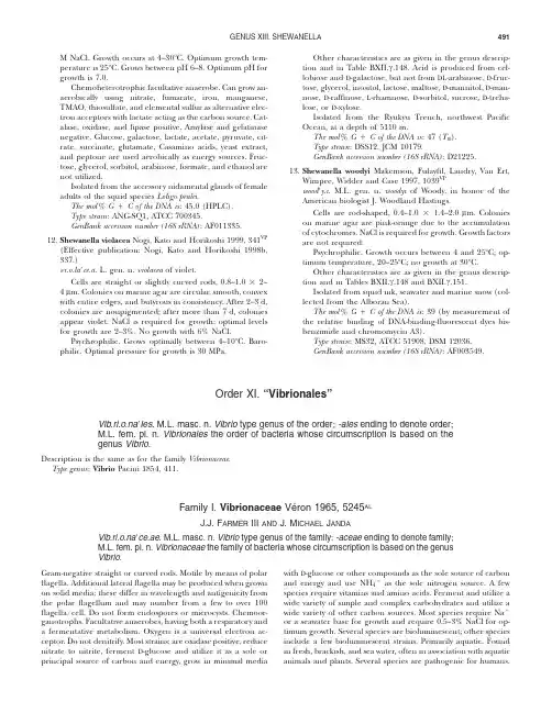
GENUS XIII.SHEWANELLA491M NaCl.Growth occurs at4–30ЊC.Optimum growth tem-perature is25ЊC.Grows between pH6–8.Optimum pH for growth is7.0.Chemoheterotrophic facultative anaerobe.Can grow an-aerobically using nitrate,fumarate,iron,manganese, TMAO,thiosulfate,and elemental sulfur as alternative elec-tron acceptors with lactate acting as the carbon source.Cat-alase,oxidase,and lipase positive.Amylase and gelatinase negative.Glucose,galactose,lactate,acetate,pyruvate,cit-rate,succinate,glutamate,Casamino acids,yeast extract, and peptone are used aerobically as energy sources.Fruc-tose,glycerol,sorbitol,arabinose,formate,and ethanol are not utilized.Isolated from the accessory nidamental glands of female adults of the squid species Loligo pealei.The mol%GםC of the DNA is:45.0(HPLC).Type strain:ANG-SQ1,ATCC700345.GenBank accession number(16S rRNA):AF011335.12.Shewanella violacea Nogi,Kato and Horikoshi1999,341VP(Effective publication:Nogi,Kato and Horikoshi1998b, 337.)Јce.a.L.gen.n.violacea of violet.Cells are straight or slightly curved rods,0.8–1.0ן2–4l m.Colonies on marine agar are circular,smooth,convex with entire edges,and butyrous in consistency.After2–3d, colonies are nonpigmented;after more than7d,colonies appear violet.NaCl is required for growth;optimal levels for growth are2–3%.No growth with6%NaCl.Psychrophilic.Grows optimally between4–10ЊC.Baro-philic.Optimal pressure for growth is30MPa.Other characteristics are as given in the genus descrip-tion and in Table BXII.c.148.Acid is produced from cel-lobiose and d-galactose,but not from dl-arabinose,d-fruc-tose,glycerol,inositol,lactose,maltose,d-mannitol,d-man-nose,d-raffinose,l-rhamnose,d-sorbitol,sucrose,d-treha-lose,or d-xylose.Isolated from the Ryukyu Trench,northwest Pacific Ocean,at a depth of5110m.The mol%GםC of the DNA is:47(T m).Type strain:DSS12,JCM10179.GenBank accession number(16S rRNA):D21225.13.Shewanella woodyi Makemson,Fulayfil,Landry,Van Ert,Wimpee,Widder and Case1997,1039VPwoodЈy.i.M.L.gen.n.woodyi of Woody,in honor of the American biologist J.Woodland Hastings.Cells are rod-shaped,0.4–1.0ן1.4–2.0l m.Colonies on marine agar are pink-orange due to the accumulation of cytochromes.NaCl is required for growth.Growth factors are not required.Psychrophilic.Growth occurs between4and25ЊC;op-timum temperature,20–25ЊC;no growth at30ЊC.Other characteristics are as given in the genus descrip-tion and in Tables BXII.c.148and BXII.c.151.Isolated from squid ink,seawater and marine snow(col-lected from the Alboran Sea).The mol%GםC of the DNA is:39(by measurement of the relative binding of DNA-binding-fluorescent dyes bis-benzimide and chromomycin A3).Type strain:MS32,ATCC51908,DSM12036.GenBank accession number(16S rRNA):AF003549.Order XI.“Vibrionales”Vib.ri.o.naЈles.M.L.masc.n.Vibrio type genus of the order;-ales ending to denote order;M.L.fem.pl.n.Vibrionales the order of bacteria whose circumscription is based on thegenus Vibrio.Description is the same as for the family Vibrionaceae.Type genus:Vibrio Pacini1854,411.Family I.Vibrionaceae Ve´ron1965,5245ALJ.J.F ARMER III AND J.M ICHAEL J ANDAVib.ri.o.naЈce.ae.M.L.masc.n.Vibrio type genus of the family;-aceae ending to denote family;M.L.fem.pl.n.Vibrionaceae the family of bacteria whose circumscription is based on the genusVibrio.Gram-negative straight or curved rods.Motile by means of polar flagella.Additional lateralflagella may be produced when grown on solid media;these differ in wavelength and antigenicity from the polarflagellum and may number from a few to over100flagella/cell.Do not form endospores or microcysts.Chemoor-ganotrophs.Facultative anaerobes,having both a respiratory and a fermentative metabolism.Oxygen is a universal electron ac-ceptor.Do not denitrify.Most strains:are oxidase positive,reduce nitrate to nitrite,ferment d-glucose and utilize it as a sole or principal source of carbon and energy,grow in minimal media with d-glucose or other compounds as the sole source of carbon and energy and use NH4םas the sole nitrogen source.A few species require vitamins and amino acids.Ferment and utilize a wide variety of simple and complex carbohydrates and utilize a wide variety of other carbon sources.Most species require Naםor a seawater base for growth and require0.5–3%NaCl for op-timum growth.Several species are bioluminescent;other species include a few bioluminescent strains.Primarily aquatic.Found in fresh,brackish,and sea water,often in association with aquatic animals and plants.Several species are pathogenic for humans.FAMILY I.VIBRIONACEAE 492Other species are pathogenic forfish,eels,and other aquatic animals.The mol%GםC of the DNA is38–51%.The family is classified in the phylum Proteobacteria in the class Gammapro-teobacteria.Type genus:Vibrio Pacini1854,411.Historical overview A history of the family Vibrionaceae as it has appeared in Bergey’s Manual is given in Table BXII.c.152. Related families include Enterobacteriaceae,Aeromonadaceae,and Pasteurellaceae.The family Vibrionaceae has undergone intense study since thefirst edition of Bergey’s Manual of Systematic Bac-teriology(Krieg and Holt,1984)was published in1984.In their chapter on the family Vibrionaceae in that edition,Baumann and Schubert(1984)included the genera Vibrio,Photobacterium,Ae-romonas,and Plesiomonas.These are the same four genera in-cluded in the original classification of the family proposed by Ve´ron almost twenty years earlier(Ve´ron,1965).In this Manual Aeromonas and Plesiomonas are classified in other families(Table BXII.c.152).For practical identification schemes,it is still useful to consider Aeromonas and Plesiomonas together with other oxidase positive genera of fermentative bacteria such as Vibrio and Pho-tobacterium(Table BXII.c.153).A detailed history of changes in the classification of Vibrio and related genera that occurred as new methods were introduced has been given by Farmer(1992). These methods include examinations of the structure,function, and regulation of proteins;comparison of mol%GםC content; DNA–DNA hybridization;rRNA–DNA hybridization;5S rRNA cataloging and sequence comparisons;and16S rRNA gene se-quence comparisons(Fig.BXII.c.157).The family Vibrionaceae presently includes three genera:Genus1.Vibrio(the type genus)Genus II.PhotobacteriumGenus III.SalinivibrioThe type strain of the type and only species of the genus Allomonas,Allomonas enterica,is very closely related to Vibrioflu-vialis by DNA–DNA hybridization studies and phenotypic analysis (Kalina et al.,1984).Allomonas and Allomonas enterica are not described separately in this edition of the Manual;the reader is referred to the description of V.fluvialis.The two species of the genus Listonella,Listonella anguillarum(the type species)and Lis-tonella pelagia,are included in the genus Vibrio in this edition of the Manual as Vibrio anguillarum and Vibrio pelagius.*F URTHER DESCRIPTIVE INFORMATIONHabitats The ecological niches of members of the family Vibrionaceae have been described by Campbell(1957);Baumann and Baumann(1981a);Sakazaki and Balows(1981);and Simidu and Tsukamoto(1985)).In humans,some vibrios cause diarrhea, wound infections,and occasionally other extraintestinal infec-tions.In aquatic animals,vibrios cause wound and generalized infections.Many vibrios and related organisms are also widely distributed in aquatic environments.Many factors govern the distribution of these organisms,but the most important probably include:particular human,animal or plant hosts;inorganic nu-trients and carbon sources available;temperature;salinity;dis-solved oxygen;and depth below the surface for the species that are found in the ocean(Simidu and Tsukamoto,1985).A few species are adapted to particular hosts.For example,Vibrio chol-erae serogroup O1is adapted to humans and is the cause of cholera,a life-threatening diarrheal disease.Recent studies have shown that the ecology of this organism is more complex than originally thought.Photobacterium leiognathi is usually isolated fromfish in shallow tropical water,and P.phosphoreum is usually found in the luminous organs offish that live at depths of200–1200meters(Hastings and Nealson,1981).Isolation Most members of the Vibrionaceae grow well on ordinary complex media.Samples are spread onto solid medium or diluted in an enrichment broth.NaCl concentrations of0.5–0.85%satisfy the requirements of most species,although a few require greater concentrations of NaCl.Incubation temperatures are also important.A few species grow only at temperatures Ͻ25ЊC;others grow at25ЊC but not at35–37ЊC.General and selective media for Vibrionaceae are described in the chapter on the genus Vibrio.Identification Methods for the isolation and identification of Vibrio spp.from clinical specimens and non-clinical samples are discussed in detail in the chapter describing the genus Vibrio. Assignment of non-clinical isolates to a species can be problem-atic because over50species of Vibrio and Photobacterium must be considered and because comparative data for these organisms are sparse relative to data available for clinically important spe-cies.The US Centers for Disease Control and Prevention maintain computer programs and databases for the identification of iso-lates subjected to a battery of45–60phenotypic tests;for details contact the Vibrio Laboratory at the CDC.These alternatives to phenotypic methods are now being used routinely and have proven extremely useful in a research setting. It will be important to evaluate the sensitivity and specificity,and to understand the advantages and disadvantages of these meth-ods.In the United States,the reporting of cultures from human specimens is subject to specific government regulations(the Clin-ical Laboratory Improvement Amendments of1988),which has limited the application of these approaches in clinical and public health laboratories.A CKNOWLEDGMENTSWe dedicate this chapter to M.Ve´ron for giving us the name Vibrionaceae and for all his contributions to our understanding of the family,its or-ganisms,and their close and distant relatives.F URTHER R EADINGBaumann,P.and L.Baumann.1977.Biology of the marine enterobac-teria:genera Beneckea and Photobacterium.Ann.Rev.Microbiol.31:39–61.Baumann,P.and L.Baumann.1981.The marine Gram-negative eubac-teria.In Starr,Stolp,Tru¨per,Balows and Schlegel(Editors),The Pro-karyotes,a Handbook on Habitats,Isolation and Identification of Bacteria,1st Ed.,Springer-Verlag,New York.pp.1352–1394. Baumann,P.,L.Baumann,S.S.Bang and M.J.Woolkalis.1980.Reeval-uation of the taxonomy of Vibrio,Beneckea,and Photobacterium:aboli-tion of the genus Beneckea.Curr.Microbiol.4:127–132. Baumann,P.,L.Baumann and M.Mandel.1971.Taxonomy of marine bacteria:the genus Beneckea.J.Bacteriol.107:268–294. Baumann,P.,A.L.Furniss and J.V.Lee.1984.Genus I.Vibrio.In Krieg and Holt(Editors),Bergey’s Manual of Systematic Bacteriology,1st Ed.,Vol.1,The Williams&Wilkins Co.,Baltimore.pp.518–538. Baumann,P.and R.H.W.Schubert.1984.Family II.Vibrionaceae.In Krieg and Holt(Editors),Bergey’s Manual of Systematic Bacteriology,1st Ed.,Vol.1,The Williams&Wilkins Co.,Baltimore.pp.516–517. Brenner,D.J.,G.R.Fanning,F.W.Hickmann-Brenner,J.V.Lee,A.G.Stei-FAMILY VIBRIONACEAE493gerwalt,B.R.Davis and J.J.Farmer.1983a.DNA relatedness among Vibrionaceae,with emphasis on the Vibrio species associated with human infection.INSERM Colloq.114:175–184.Chakraborty,S.,G.B.Nair and S.Shinoda.1997.Pathogenic vibrios in the natural aquatic environment.Rev.Environ.Health.12:63–80. Farmer,J.J.1992.The family Vibrionaceae.In Balows,Tru¨per,Dworkin,Harder and Schleifer(Editors),The Prokaryotes.A Handbook on the Biology of Bacteria:Ecophysiology,Isolation,Identification,Ap-plications,2nd Ed.,Vol.3,Springer-Verlag,New York.pp.2938–2951. Farmer,J.J.,M.J.Arduino and F.W.Hickman-Brenner.1992.Aeromonas and Plesiomonas.In Balows,Tru¨per,Dworkin,Harder and Schleifer (Editors),The Prokaryotes.A Handbook on the Biology of Bacteria:FAMILY I.VIBRIONACEAE 494GENUS I.VIBRIO495FIGURE BXII.c.157.Relationship of most of the species of Vibrio and relatives based on16S rRNA gene sequences.* Only the type strain of each species was included.The distances in the tree were calculated using1101positions (the least-squares method,Jukes-Cantor model).(Courtesy T.Lilburn of the Ribosomal Database Project.)*Editorial Note:Photobacterium damselae subsp.damselae is a junior objective synonym of Vibrio damsela.Vibrio pelagius and Vibrio anguillarum are synonyms of Listonella pelagia and Listonella anguillarum,respectively.and volume(15–67%)and a conversion of rods into coccal forms called spherical ultramicrocells(Holmquist and Kjelleberg,1993; Kondo et al.,1994;Nelson et al.,1997).As the length of nutrient starvation increases,cytoplasmic inclusions and granules disap-pear,cell cultivability decreases,and the nuclear region becomes compressed(Hood et al.,1986).There are also noticeable dif-ferences in the integrity of the outer membrane and cell wall. Some changes may be linked to specific nutrient starvation(for example,nitrogen starvation produces longfilaments and phos-phorus starvation produces swollen large rods),whereas others occur regardless of the type of nutritional stress(Holmquist and Kjelleberg,1993).“Non-culturable”V.cholerae O1strains pro-duced in response to nutrient deprivation display a number of ultrastructural changes,which include an undulating outer mem-brane,a surface layer offinefibers,and a thicker peptidoglycan layer(Kondo et al.,1994).FAMILY I.VIBRIONACEAE 496Poly-b-hydroxybutyrate granules(PHB)can be found in a number of Vibrio species,including V.cholerae O1and O139and V.harveyi(Hood et al.,1986;Sun et al.,1994;Finkelstein et al., 1997).In V.cholerae,accumulation of PHB appears to be related to colonial opacity and growth on glycerol-containing media(Fin-kelstein et al.,1997).In V.harveyi,PHB accumulation is de-pendent on cell density and is controlled by the autoinducer,N-(3-hydroxybutanoyl)homoserine lactone(Sun et al.,1994). Other kinds of granules can be found in vibrios,including elec-tron dense lipoid particles and electron translucent inclusions of unknown composition(Sun et al.,1994;Finkelstein et al., 1997).Cell wall composition Vibrios contain the same three lipo-polysaccharide(LPS)elements found in other Gram-negative bacteria:lipid A,core polysaccharide,and an O polysaccharide side chain that determines serological specificity.The most ex-tensive work on biochemical characterization of Vibrio LPS has been done on V.cholerae.The lipid A portion consists of a b(1Ј-6)-linked glucosamine disaccharide backbone with two phos-phoryl groups(Janda,1998).Pyrophosphorylethanolamine is linked to one of these phosphoryl groups at the C-1position of the reducing sugar,and a phosphate group ester is bound to the nonreducing glucosamine residue(Manning et al.,1994).Three fatty acids are ester linked at hydroxyl positions to this disaccha-ride backbone:tetradecanoic acid(C14:0),hexadecanoic acid (C16:0),and3-hydroxydodecanoic acid(C12:03OH).A fourth,3-hydroxytetradecanoic acid(C14:03OH),is connected to the back-bone by an amide bond.The core oligosaccharide region of V.cholerae contains KDO (keto-3-deoxy-d-mannose-octulosonic acid),d-glucose,heptose (l-glycero-d-manno-heptose),d-fructose,and ethanolamine phosphate(Manning et al.,1994).KDO,a normal constituent of the core oligosaccharide of enteric LPS,was originally thought to be absent in Vibrio species.However,when conventional per-iodate-thiobarbituric acid tests were replaced by strong acid hy-drolysates,KDO was detected in Vibrio(Janda,1998).The KDO molecule of V.cholerae differs in several aspects from those of enteric bacteria such as Escherichia coli and the genus Salmonella: only a single KDO molecule has been detected in the core oli-gosaccharide of V.cholerae,and the KDO moiety is phosphory-lated at the C4position(Kondo et al.,1990;Manning et al., 1994).The C5position binds to a distal portion of the core region (heptose)similar to the KDO-C5binding of l-glycero-d-manno-heptose(Janda,1998).The other sugars form the remaining portion of the core oligosaccharide region and often contain additional sugar substitutions at various positions.The O-polysaccharide side chain of V.cholerae O1is a homo-polymer of d-perosamine(4,6-dideoxy-d-mannose)approxi-mately17–18units in length(Manning et al.,1994;Knirel et al., 1997).The amino groups of perosamine units are commonly acetylated with3-deoxy-l-glycero-tetronic acid.Another com-pound,quinovosamine,is thought to be a“capping sugar”on either the distal or the proximal end of the O antigen(Manning et al.,1994).An unusual sugar,4-amino-4,6-dideoxy-2-O-methyl-mannose is present only in the LPS of serogroup Ogawa and may have a role in serological specificity(Itoh et al.,1994).The LPS composition of V.cholerae O139—a second serotype capable of causing pandemic cholera—is remarkably similar to that of O1(Hisatsune et al.,1993;Isshiki et al.,1996).The lipid A moieties of O1and O139,including fatty acid substitutions, appear to be identical(Hisatsune et al.,1993).The core oligo-saccharide region contains two subtle differences:the presence of2-aminoethyl phosphate,which is the O-acetyl group,and the presence of a second fructose molecule(Knirel et al.,1997).The most profound differences between O-groups1and139occur in the O-polysaccharide side chain.Unlike serogroup O1,which has long O-polysaccharide side chains,V.cholerae O139has a short chain LPS similar to“SR strains”(Knirel et al.,1997).These truncated side chains migrate with the core oligosaccharide-lipid A fraction in LPS SDS-PAGE gels(Waldor et al.,1994).Classic “ladder-like”profiles of silver stained LPS side chains in SDS-PAGE gels are absent in O139strains(Hisatsune et al.,1993; Nandy et al.,1995).Perosamine,the main component of the O1 side chain,is also absent in O139strains(Hisatsune et al.,1993); instead,the unique sugar colitose(3,6-dideoxy-l-galactose)—which is not found in any other Vibrio species—is the main side chain subunit in O139strains(Hisatsune et al.,1993).The ab-breviated O-polysaccharide side chain of V.cholerae O139appears to be a hexasaccharide containing colitose residues and a cyclic phosphate group(Knirel et al.,1997).The LPS of other Vibrio species is similar in many aspects to that of O139.KDO-phosphate has been detected in V.parahaemolyticus by gas chromatography-mass spectrometry analysis(Janda,1998).The O-polysaccharide side chains of Vibrio species produce only a single fast-migrating band on silver-stained SDS-PAGE gels(Amaro et al.,1992;Iguchi et al.,1995).This result suggests that the side chains are short;a chain length ofՅ10monosaccharides has been proposed for V.parahaemolyticus(Iguchi et al.,1995).Some species however (e.g.,V.vulnificus)may exhibit ladder-like patterns by immu-noblotting with whole cell antisera;this result suggests that the LPS O-polysaccharide side chains are mbert et al.(1983) studied the cellular fatty acids of most of the Vibrionaceae and postulated that differences among the Vibrio species might prove useful for identification.Flagella Two types offlagella are synthesized by vibrios in different environments.In liquid culture,swimmer cells predom-inate due to production of a single sheathed polarflagellum in most species(Figs.BXII.c.158and BXII.c.159).The sheath is an extension of the outer membrane(Fig.BXII.c.160).The polar flagella are24–30nm in diameter with a central core14–16nm in thickness with a wavelength of1.4–1.8l m(Baumann et al., 1984b;Janda,1998).Some Vibrio species(e.g.,V.harveyi,V.fischeri, V.logei,and V.salmonicida)produce tufts(3–12)of polarflagella (Fig.BXII.c.161)with a wavelength of approximately3.6l m (Baumann et al.,1984b;Ishimaru et al.,1996).Polarflagella provide chemotactic motility in liquid media and derive their energy from the sodium membrane potential(McCarter,1995). In some marine vibrios(e.g.,V.anguillarum),the polarflagellum appears critical for disease production in estuarinefish(Milton et al.,1996;O’Toole et al.,1996).When vibrios come into contact with solid surfaces,a series of morphogenetic changes are ini-tiated that result in the conversion of swimmer cells into swarmer cells in some marine species such as V.parahaemolyticus,V.algi-nolyticus,V.diabolicus,and V.pectenicida(Rague´ne`s et al.,1997a; Lambert et al.,1998).During this process,cell septation ceases, the cells elongate from1to30l m,and numerous lateralflagella are formed(Fig.BXII.c.162)(McCarter and Silverman,1990). These lateralflagella,14–15nm in diameter with a wavelength of0.9l m,are distinct from polarflagella.They are unsheathed, have a different protein subunit composition,and are internally driven by the protonmotive force(Baumann et al.,1984b; McCarter,1995).Formation of lateralflagella permits swarmerGENUS I.VIBRIO497FIGURE BXII.c.158.Leifsonflagella stain of Vibrio cholerae.(Source:CDC archive,courtesy of EdEwing.)FIGURE BXII.c.159.Electron micrograph of Vibrio alginolyticus grown in liquid medium.Note the sheathed polarflagellum and absence of pe-ritrichousflagella.Shadowed preparation.ן13,000.(Reproduced with permission from C.Golten and W.A.Scheffers,Netherlands Journal of Sea Research9:351–364,1975,᭧Netherlands Institute for SeaResearch.)FIGURE BXII.c.160.Electron micrograph of a polarflagellum of Vibrio alginolyticus.Note that the sheath has partially disintegrated exposing the inner core.Negatively stained preparation.ן30,000.(Courtesy of R.D. Allen.)migration across solid surfaces and results in progressive spread-ing of the bacterial colony(McCarter and Silverman,1990),a phenomenon called swarming.Swarming in many vibrio species is dependent upon a number of factors including agar concen-tration,media composition,iron availability,temperature,and relative viscosity(Baumann et al.,1984b;McCarter and Silver-man,1990).The microscopic morphology of vibrio cells removed from different concentric zones of swarming has been studied in some Vibrio strains(Sar and Rosenberg,1989).Innermost zones consist of irregular cells including bent rods that pro-gressively evolve into short rods and then into large rods with bundles of detachedflagella(Fig.BXII.c.163),whereas cells inFAMILY I.VIBRIONACEAE498FIGURE BXII.c.161.Electron micrograph of Vibriofischeri.Note the tufts of sheathed polarflagella.Negatively stained preparation.ן23,000. (Reproduced with permission from:J.L.Reichelt and P.Baumann,Ar-chives of Mikrobiology94:283–330,1973,᭧Springer-Verlag,Berlin.)FIGURE BXII.c.162.Electron micrograph of Vibrio alginolyticus grown on solid medium.Note the thick,sheathedflagellum and numerous un-sheathed lateralflagella.Shadowed preparation.ן18,000.(Reproduced with permission from W.E.de Boer et al.,Netherlands Journal of Sea Research9:197–213,1975,᭧Netherlands Institute for Sea Research.)the outermost circles of swarming colonies consist of longfila-mentous forms.Fimbriae Fimbriae are produced by a number of pathogenic vibrios such as V.cholerae O1and non-O1,V.parahaemolyticus, and V.vulnificus(Hall et al.,1988;Honda et al.,1988;Gander and LaRocco,1989;Nakasone and Iwanaga,1990).Several dif-ferent morphologic types offimbriae have been described in V. cholerae O1.These include both wavy pili3nm in diameter and rigidfilaments5–6nm wide and180–800nm in length(Hall et al.,1988).The most important of these pili is composed of the protein TcpA;these pili are5–6nm wide and form bundles of parallel undulatingfilaments up to15l m long(Hall et al.,1988). TcpA formation is coregulated with cholera toxin expression and is a key determinant of in vivo colonization.The gene encoding TcpA appears to reside on a pathogenicity island.Capsules Capsules have been detected surrounding cells of strains of V.cholerae O139and V.vulnificus strains with a variety of staining techniques such as uranyl acetate,polycationic fer-ritin,and ruthenium red(Janda,1998).The V.vulnificus poly-saccharide capsule is60nm thick and has a low electron density (Amako et al.,1984;Hayat et al.,1993).The carbohydrate com-position of the capsule of V.vulnificus varies from strain to strain. Sugars detected in different isolates include␣-N-acetyl quino-vosamine,␣-N-acetyl galactosamine uronic acid,rhamnosamine, and fucosamine(Hayat et al.,1993).Colonial morphology Most vibrios grow well on a variety of media,including protein-based agars and marine and seawater media,if sufficient Naםis present(Baumann et al.,1984b; Farmer and Hickman-Brenner,1992).On most selective media, vibrios appear as smooth,buff-to-cream-colored colonies2–5mm in diameter,with an entire margin after overnight incubation (Baumann et al.,1984b;Janda,1998).Some species tend to pro-duce grayish colonies,particularly on blood agar.Considerable variation in colonial morphology has been reported for some species,and this is best demonstrated by observing colonies with a dissecting microscope at10–25magnification with oblique lighting.V.cholerae strains can have several different colonial mor-phologies(smooth,rough,and rugose forms)in response to different growth conditions.Rugose colonies are often chlorine-resistant.They are usually found in older cultures and are com-posed of an amorphous intercellular matrix of aggregated bac-teria and exopolysaccharide material(Morris et al.,1996).For-mation of rugose colonies can be enhanced by growth in en-richment broths such as alkaline peptone water(APW)or by picking the growth that has migrated up the sides of a culture tube.They can largely be avoided by picking a smooth colony and freezing it.In addition to these colony types,several path-GENUS I.VIBRIO499FIGURE rge bundle offlagella in a culture of Vibrio harveyi. These bundles are frequently observed in cultures grown on solid me-dium.Negatively stained preparation.ן13,000.(Courtesy of R.D.Allen.) ogenic vibrios,including V.cholerae and V.vulnificus,produce opaque and translucent varieties of smooth colonies on common media such as heart infusion and meat extract agars(Simpson et al.,1987;Finkelstein et al.,1992,1997).Cells from colonies of these different morphologies differ from each other in a num-ber of characteristics,including encapsulation,cell surface com-position,cellular metabolism,and ability to survive under adverse conditions.Pigmentation Several Vibrio species produce pigmented col-onies.V.nigripulchritudo produces an insoluble blue-black pig-ment that accumulates in a crystalline form within the colonies (Baumann et al.,1984b).Other Vibrio species also produce blue-black crystals under various growth conditions,but typically do not produce the characteristic blue-black colonies of V.nigripul-chritudo.Similar blue-black colonies are produced by a few strains of Kluyvera(Farmer et al.,1981a).Other pigmented species in-clude V.gazogenes(red)and V.fischeri and V.logei(yellow-orange).A few strains of V.cholerae produce a brown diffusible melanin-like pigment(Ivins and Holmes,1980).Life cycles The marine environment is the natural habitat of vibrios,and the life cycle of these organisms is probably quite complex.A model for the life of V.cholerae in Gulf Coast estuaries has been proposed(Hood et al.,1984).Depending on nutrient scarcity and the density/availability of particulate matter,V.chol-erae can exist in several states.An epibiotic form attached to plankton predominates during periods of relatively high nu-trient/particulate matter concentrations;this form changes to a microvibrio form(small rounded cells)during times of nutrient and particulate deprivation(Hood et al.,1984;Janda,1998).This latter form may be analogous to the“viable but nonculturable state”(Colwell,1984)that has been described for many Vibrio species including V.cholerae,V.parahaemolyticus,V.vulnificus,V. anguillarum,V.campbellii,V.harveyi,and V.fischeri during colder seasons of the year(Oliver,1995).The microvibrio and“non-culturable”stages may be dormant phases for vibrios in winter from which subsequent blooms are triggered in response to in-creasing temperatures in spring and summer.However,it is still unclear whether any dormant state actually exists and whether blooms are due to the growth of a small number of cultivable cells(present at all times)or the actual resuscitation of dormant cells(Ravel et al.,1995;Bogosian et al.,1998).Nutrition and growth conditions Vibrio species vary in their nutrition and growth requirements.The most important feature is that Naםis required for or stimulates growth.Minimum con-centrations of Naםrequired for optimal growth(Fig.BXII.c.164) range from5–15mM(0.029–0.087%)for V.cholerae and V.metsch-nikovii to600–700mM(3.5–4.1%)for Salinivibrio costicola(Bau-mann et al.,1984b).Most species grow well in solid or liquid media containing0.5–2%NaCl.Some species(Photobacterium ili-opiscarium)form bacterial aggregates in broth culture containing 2%NaCl(Onarheim et al.,1994).The“salt requirement”of a strain will often depend on the test conditions.The main variables are temperature,the growth medium used prior to testing,the suspending medium,and the testing medium.All Vibrio species except V.cholerae and V.mimicus have an absolute requirement for Naם(Fig.BXII.c.164).In some instances,this requirement may be partially offset by concentra-tions of Mg2םor Ca2םsimilar to those normally present in sea-water(Baumann et al.,1984b).However,most species exhibit a specific requirement for Naם(Pujalte and Garay,1986;Borrego et al.,1996).The range and optimum concentrations of NaCl supporting growth of some of the more recently described Vibrio species are listed in Table BXII.c.154.No single medium or NaCl concentration is optimal for the recovery or growth of all Vibrio species.Many vibrios will grow in mildly alkaline conditions.Al-though most species prefer a pH range of7–8(Rague´ne`s et al., 1997a),some species,including V.cholerae and V.metschnikovii, will even grow at a pH of10(Baumann et al.,1984b).Vibrios also vary in their temperature requirements for growth.Almost all Vibrio species grow well at18–22ЊC.Some will grow at0–4ЊC,whereas others can grow at temperatures up to 45ЊC.The temperature at which vibrios can grow is also de-pendent upon other factors including the composition of the medium and the NaCl concentration(Onarheim et al.,1994).Most Vibrio species do not require specific organic growth factors such as vitamins or amino acids,although amino acid supplementation may be required to revive some strains stored for prolonged periods(Baumann et al.,1984b).Complex nu-trients are required to induce growth of some species(Baumann et al.,1984b;Rague´ne`s et al.,1997a).Such required supplements include yeast extract(for V.anguillarum,Moritella marina,and V. logei)and a seawater base(for V.diabolicus).Vibrios use a variety of compounds as carbon and energy。
Mirror stageLacan's first official contribution to psychoanalysis was the mirror stage, which he described as "formative of the function of the I as revealed in psychoanalytic experience." By the early 1950s, he came to regard the mirror stage as more than a moment in the life of the infant; instead, it formed part of the permanent structure of subjectivity. In "the Imaginary order," their own image permanently catches and captivates the subject. Lacan explains that "the mirror stage is a phenomenon to which I assign a twofold value. In the first place, it has historical value as it marks a decisive turning-point in the mental development of the child. In the second place, it typifies an essential libidinal relationship with the body-image".[35]As this concept developed further, the stress fell less on its historical value and more on its structural value.[36] In his fourth Seminar, "La relation d'objet," Lacan states that "the mirror stage is far from a mere phenomenon which occurs in the development of the child. It illustrates the conflictual nature of the dual relationship."The mirror stage describes the formation of the Ego via the process of objectification, the Ego being the result of a conflict between one's perceived visual appearance and one's emotional experience. This identification is what Lacan called alienation. At six months, the baby still lacks physical co-ordination. The child is able to recognize themselves in a mirror prior to the attainment of control over their bodily movements. The child sees their image as a whole and the synthesis of this image produces a sense of contrast with the lack of co-ordination of the body, which is perceived as a fragmented body. The child experiences this contrast initially as a rivalry with their image, because the wholeness of the image threatens the child with fragmentation—thus the mirror stage gives rise to an aggressive tension between the subject and the image. To resolve this aggressive tension, the child identifies with the image: this primary identification with the counterpart forms the Ego.[36] Lacan understands this moment of identification as a moment of jubilation, since it leads to an imaginary sense of mastery; yet when the child compares their own precarious sense of mastery with the omnipotence of the mother, a depressive reaction may accompany the jubilation.[37]Lacan calls the specular image "orthopaedic," since it leads the child to anticipate the overcoming of its "real specific prematurity of birth." The vision of the body as integrated and contained, in opposition to the child's actual experience of motor incapacity and the sense of his or her body as fragmented, induces a movement from "insufficiency to anticipation."[38] In other words, the mirror image initiates and then aids, like a crutch, the process of the formation of an integrated sense of self.In the mirror stage a "misunderstanding" (méconnaissance) constitutes the Ego—the "me" (moi) becomes alienated from itself through the introduction of an imaginary dimension to the subject. The mirror stage also has a significant symbolic dimension, due to the presence of the figure of the adult who carries the infant. Having jubilantly assumed the image as their own, the child turns their head towards this adult, who represents the big Other, as if to call on the adult to ratify this image.[39]35. Lacan, J., "Some Reflections on the Ego" in Écrits36.Dylan Evans, An Introductory Dictionary of Lacanian Psychoanalysiscan, J., "La relation d'objet" in Écrits.can, J., "The Mirror Stage as Formative of the Function of the I", in Écrits: a selection, London, Routledge Classics, 2001; p. 5can, Tenth Seminar, "L'angoisse," 1962–1963。

《冰与火之歌》专有名词中英文对照表A song of ice and fire 冰与火之歌一、人名Eddard艾德Catelyn 凯特琳Rob 罗柏Arya艾莉亚Brandon(Bran) 布兰登(布兰)Rickon 瑞肯Sansa 珊莎Maester Luwin 鲁温学士Jon Snow 琼恩?雪诺Samwell Tarly 山姆威尔塔利Jeor Mormont 杰奥莫尔蒙Qhorin Halfhand 科林断掌Benjen Stark 班扬史塔克Maester Aemon伊蒙学士Robert 劳勃Melisandre梅莉珊卓Davos Seaworth 戴佛斯席渥斯V arys 瓦里斯Brienne of Tarth 塔斯的布蕾妮Sandor Clegane 桑铎克里冈Lysa Arryn 莱莎艾林Loras Tyrell 洛拉斯提利尔Margaery Tyrell 玛格利提利尔Olenna Tyrell 奥莲娜提利尔Mace Tyrell梅斯提利尔Tyrion Lannister(Imp)提利昂.兰尼斯特(小恶魔)Ser Bronn波隆爵士Podrick Payne(Pod)波德瑞克.派恩(波德)Lord Tywin Lannister泰温.兰尼斯特公爵Ser Addam Marbrand亚当.马尔布兰爵士Ser Meryn Trant马林.特兰爵士Ser Osmund Kettleblack奥斯慕.凯特布雷克爵士Queen Cersei瑟曦太后Ser Mandon Moore曼登.穆尔爵士Hound猎狗Ser Jacelyn Bywater(Ironhand)杰斯林.拜瓦特爵士(铁手) King Joffery乔佛里国王Osney奥斯尼Osfryd奥斯弗德Jaime詹姆Shagga夏嘎Timett提魅Chella齐拉Alayaya(Y aya)爱拉雅雅(雅雅)Shae雪伊Tommen托曼Stannis史坦尼斯Renly蓝礼Robb Stark(Y oung Wolf)罗柏.史塔克(少狼主)Lord Tarly塔利伯爵Ser Kevan凯冯爵士Margaery Tyrell玛格丽.提利尔Maester Frenken法仁肯学士Lord Rowan罗宛大人Lord Redwyne雷德温大人Lord Baelish(Littlefinger)贝里席大人(小指头)Tyrek提瑞克Tygerr提盖特Lady Ermesande艾弥珊德伯爵小姐Hayford海佛德Maester Ballabar巴拉巴尔学士Helman Tallhard赫曼.陶哈Robbet Clover罗贝特.葛洛佛Ser Gregor Clegane格雷果.克里冈爵士Roose Bolton卢斯.波顿Aerys伊里斯Baratheon拜拉席恩Myrcella弥赛拉Ser Arys Oakheart亚历斯.奥克赫特爵士Princess Arianne爱瑞安公主Prince Trystane崔斯丹亲王Martell马泰尔Prince Doran道朗亲王Tysha泰莎二、地名THE FROZEN SHORE 冰封海岸BAY OF ICE 寒冰湾BEAR’S ISLAND 熊岛SEA DRAGON POINT 海龙角DEEPWOOD MOTTE 深林堡WOLFSWOOD 狼林THE HAUNTED FORSET 鬼影森林THE WALL 绝境长城SHADOW TOWER 影子塔CASTLE BLACK 黑城堡EASTWA TCH-BY-THE-SEA 东海望LAST HEARTH 最后壁炉城SKAGOS 斯卡格斯岛QUEEN’S CROWN 后冠镇KARHOLD 卡霍城THE DREADFORT 恐怖堡THE LAST RIVER 末江THE KING’S ROAD 国王大道LONG LAKE 长湖WINTERFELL 临冬城TORRHEN’S SQUARE 托伦方城BARROWLANDS 先民荒冢THE RILLS 溪流地STONY SHORE 磐石海岸BLAZEWA TER BAY 明焰湾SAL TSPEAR 盐矛滩CAPE KRAKEN 海怪角SEAGUARD 海疆城THE TWINS 孪河城GRA YWA TER WA TCH 灰水望IRONMAN’S BA Y 铁民湾IRON ISLANDS 铁群岛blacktyde 黑潮岛orkmont 奥克蒙岛harlaw 哈尔洛岛old wyk 老威克岛great wyk 大威克岛salt cliffe 盐崖岛pyke 派克岛GREEN FORK 绿叉河BLUE FORK 蓝叉河RED FORK 红叉河tumblestone 腾石河riverrun 奔流城V ALE OF ARRYN 艾林谷THE EYRIE 鹰巢城BLOODY GA TE 血门THE FINGERS 五指半岛THE BITE 咬人湾THREE SISTER 三姐妹群岛pebble 卵石岛THE PAPS 乳头岛THE NECK 颈泽MOA T CALIN 卡林湾WHITE HARBOUR 白港WHTIE KNIFE 白刃河BAY OF SEALS 海豹湾WIDOW’S WA TCH 寡妇望THE FLINT CLIFFS 菲林特悬崖FLINT'S FINGER 菲林特之指THREE SISTERS 三姐妹群岛THE FINGERS 五指半岛pebble 卵石岛THE PAPS 乳头岛longbow hall 长弓厅heart's home 心宿城ironoaks 铁橡城old anchor 老锚地runestone 符石城Gulltown 海鸥镇THE TWINS 孪河城CAPE OF EAGLES 雄鹰角seagard 海疆城GREENFORK 绿叉河KINGSROAD 国王大道THE TRDIENT 三叉戟河BLUE FORK 蓝叉河Oldstones 荒石城FAIRMARKET 美人市集RED FORK 红叉河saltpans 盐场镇tumblestone 腾石河INN OF THE KNEELING MAN 屈膝之栈IRON ISLANDS 铁群岛blacktyde 黑潮岛orkmont 奥克蒙岛harlaw 哈尔洛岛old wyk 老威克岛great wyk 大威克岛salt cliffe 盐崖岛pyke 派克岛IRONMAN'S BAY 铁民湾riverrun 奔流城high heart 高尚之心acorn hall 橡果厅pinkmaiden 红粉城GOLDEN TOOTH 金牙城THE CRAG 峭岩城ASHMARK 烙印城FAIR ISLE 仙女群岛faircastle 仙女城CASTERL Y ROCK 凯岩城feastfires 宴火城RIVER ROAD 河间大道GOLD ROAD 黄金大道kayce 凯切镇stony sept 石堂镇lannisport 兰尼斯港lord harroway's town 哈罗威伯爵的小镇GOD’EYE 神眼湖ISLE OF FACES 千面屿HARRENDAL 赫伦堡MAIDENPOOL 女泉城BAY OF CRABS 螃蟹湾CRACKCLA W POINT 蟹爪半岛dragonstone 龙石岛driftmark 潮头岛rosby 罗斯比城duskendale 暮谷城KING’S LANDING 君临ROSE ROAD 玫瑰大道MANDER 曼德河blackwater RUSH 黑水河BLACKEWARER BAY 黑水湾the gullet 喉道sharp point 尖角SIL VERHILL 银山城CRAKEHALL 秧鸡厅OLD OAK 古橡城THE REACH 河湾地OCEAN ROAD 滨海大道BITTERBRIDGE 苦桥goldengrove 金树城blue byrn 蓝布恩河grassy vale 绿谷城longtable 长桌堡ashford 白杨滩cider hall 果酒厅cockleswent 舟徙河highgarden 高庭shield islands 盾牌列岛brightwater keep 亮水城hornhill 角陵nightsong 夜歌城honeyholt 蜂巢城honeywine 蜂酒河old town 旧镇three towers 三塔堡blackcrown 黑冠城whispering sound 低语湾KING’S WOOD 御林WENDWA TER 文德河MASSEY'S HOOK 马赛岬bronzegate 铜门城TARTH 塔斯岛evenfall 暮临厅storm's end 风息堡summerhall 盛夏厅blackhaven 黑港boneway 骨路CAPE WARTH 风怒角rainwood 雨林estermont 伊斯蒙岛mistwood 雾林城greenstone 绿石堡wyl 维尔城blackmont 布莱蒙城kingsgrave 王冢城yronwood 伊伦伍德城prince's pass 亲王隘口starfall 星坠城sandstone 沙石城brimstone 硫磺河hellholt 狱门堡the scourge 祸江the vaith 万斯河V AITH 万斯城salt shore 盐海岸greenblood 绿血河lemonwood 柠檬林sunspear 阳戟城THE TOR 托尔城ghosthill 魂丘THE BROKEN ARM 断臂角THE ARBOR 青亭岛三、其它High Septon大主教Kingsguard(White Swords)御林铁卫(白剑士) City Watch都城守备队Stone Crows石鸦部Burned Men灼人部Black Ears黑耳部Lyseni里斯人seven hells七层地狱Hand首相pyromancer火术士wildfire 野火clansmen高山部族。

医学英语术语解密_福建医科大学中国大学mooc课后章节答案期末考试题库2023年1.The combining form indicating a collection of capillaries in the kidneyis_______.答案:glomerul/o2.At the end stage of renal failure, there would be little or no production ofurine. This condition is termed _________.答案:anuria3.The outer part of the kidney is called_______________.答案:cortex4. A ____________ is a surgical incision into the kidney to remove stones.答案:nephrolithotomy5.The temporary reservoir for urine in the body is___________.答案:bladder6.Surgical repair of the rectum is called__________.答案:rectoplasty7. A dangerous twisting of the colon is called__________.答案:volvulus8.The condition known as stomatitis occurs in the __________.答案:mouth9.Paralytic obstruction is also known as_____________ obstruction.答案:Adynamic10._________ thermometer can be used in taking temperature for achild.答案:Rectal11.What is the test used to examine the nasal passages and the pharynx todiagnose structural abnormalities?答案:Nasopharyngoscopy.12.The air sacs through which gases are exchanged in the lungs are the___________.答案:alveoli13.The membrane surrounding the lungs is ___________.答案:pleura14.The term for the measurement of the movement of air in and out of the lungsduring various breathing maneuvers is ___________, which is the mostimportant pulmonary function test.答案:spirometry15.The __________ is the inner lining of the heart.答案:endocardium16.The two upper receiving chambers of the heart are called the right and left_________.答案:atria17.The mitral valve has __________ cusps or leaflets that open and close.答案:two18.__________ refers to the contraction phase of the ventricles in the heartbeatcycle.答案:Systole19.__________ is any irregularity of heart rhythm, such as an altered heart rate,extra beats, or a change in the pattern of the beat.答案:Arrhythmia20.The word "osteorrhaphy" should be pronounced as ________.答案:/ˌɔsti'ɔrəfi/21.Which of the following the correct pronunciation of "stomatoplasty"?答案:/ˈstəʊmətəˌplæstɪ/22.Which suffix indicates stopping, controlling?答案:-stasis23.Which suffix indicates discharge?答案:-rrhea24.Which prefix indicates between, among?答案:inter-25. A ______ is the smallest meaningful unit of a language.答案:morpheme26.How to pronounce the word peritonitis?答案:/ˌperɪtəˈnaɪtɪs/27.An orthodontist a dentist specializing in the prevention or correction ofirregularities of the teeth.答案:正确28.Etymology refers to the study of the origins of words.答案:正确29. The rod of Asclepius, a snake-entwined staff, remains a symbol of medicinetoday.答案:正确30.The plural form of "metastasis" is "metastases".答案:正确31.The terminology for the surgical removal of a kidney and a ureter isnephroureterectomy.答案:正确32.Jennie complained of painful urination. The medical term for this ishematuria.答案:错误33.Urethritis is the inflammation of urethra due to injury or infection.答案:正确34.Any minute globular particle is called corpus.答案:错误35. A dilatation of a calix of the kidney, usually due to obstruction or infection isnamed caliectasis.答案:正确36. A cell that engulfs and digests debris and invading microorganisms is knownas phagocyte.答案:正确37.Appendectomy is the surgical removal of appendix.答案:正确38.The combining form for “arteriole” is “arteri/o”.答案:错误39.“Thrombectomy” means excision of a clot from a blood vessel.答案:正确40.The word meaning pertaining to the pericardium is “pericardiac”.答案:错误41.The synonym for spir/o is hal/o.答案:正确。
21-centimeter line, 21厘米线AAbsorption, 吸收Addition of angular momenta, 角动量叠加Adiabatic approximation, 绝热近似Adiabatic process, 绝热过程Adjoint, 自伴的Agnostic position, 不可知论立场Aharonov-Bohm effect, 阿哈罗诺夫-玻姆效应Airy equation, 艾里方程;Airy function, 艾里函数Allowed energy, 允许能量Allowed transition, 允许跃迁Alpha decay, 衰变;Alpha particle, 粒子Angular equation, 角向方程Angular momentum, 角动量Anomalous magnetic moment, 反常磁矩Antibonding, 反键Anti-hermitian operator, 反厄米算符Associated Laguerre polynomial, 连带拉盖尔多项式Associated Legendre function, 连带勒让德多项式Atoms, 原子Average value, 平均值Azimuthal angle, 方位角Azimuthal quantum number, 角量子数BBalmer series, 巴尔末线系Band structure, 能带结构Baryon, 重子Berry's phase, 贝利相位Bessel functions, 贝塞尔函数Binding energy, 束缚能Binomial coefficient, 二项式系数Biot-Savart law, 毕奥-沙法尔定律Blackbody spectrum, 黑体谱Bloch's theorem, 布洛赫定理Bohr energies, 玻尔能量;Bohr magneton, 玻尔磁子;Bohr radius, 玻尔半径Boltzmann constant, 玻尔兹曼常数Bond, 化学键Born approximation, 玻恩近似Born's statistical interpretation, 玻恩统计诠释Bose condensation, 玻色凝聚Bose-Einstein distribution, 玻色-爱因斯坦分布Boson, 玻色子Bound state, 束缚态Boundary conditions, 边界条件Bra, 左矢Bulk modulus, 体积模量CCanonical commutation relations, 正则对易关系Canonical momentum, 正则动量Cauchy's integral formula, 柯西积分公式Centrifugal term, 离心项Chandrasekhar limit, 钱德拉赛卡极限Chemical potential, 化学势Classical electron radius, 经典电子半径Clebsch-Gordan coefficients, 克-高系数Coherent States, 相干态Collapse of wave function, 波函数塌缩Commutator, 对易子Compatible observables, 对易的可观测量Complete inner product space, 完备内积空间Completeness, 完备性Conductor, 导体Configuration, 位形Connection formulas, 连接公式Conservation, 守恒Conservative systems, 保守系Continuity equation, 连续性方程Continuous spectrum, 连续谱Continuous variables, 连续变量Contour integral, 围道积分Copenhagen interpretation, 哥本哈根诠释Coulomb barrier, 库仑势垒Coulomb potential, 库仑势Covalent bond, 共价键Critical temperature, 临界温度Cross-section, 截面Crystal, 晶体Cubic symmetry, 立方对称性Cyclotron motion, 螺旋运动DDarwin term, 达尔文项de Broglie formula, 德布罗意公式de Broglie wavelength, 德布罗意波长Decay mode, 衰变模式Degeneracy, 简并度Degeneracy pressure, 简并压Degenerate perturbation theory, 简并微扰论Degenerate states, 简并态Degrees of freedom, 自由度Delta-function barrier, 势垒Delta-function well, 势阱Derivative operator, 求导算符Determinant, 行列式Determinate state, 确定的态Deuterium, 氘Deuteron, 氘核Diagonal matrix, 对角矩阵Diagonalizable matrix, 对角化Differential cross-section, 微分截面Dipole moment, 偶极矩Dirac delta function, 狄拉克函数Dirac equation, 狄拉克方程Dirac notation, 狄拉克记号Dirac orthonormality, 狄拉克正交归一性Direct integral, 直接积分Discrete spectrum, 分立谱Discrete variable, 离散变量Dispersion relation, 色散关系Displacement operator, 位移算符Distinguishable particles, 可分辨粒子Distribution, 分布Doping, 掺杂Double well, 双势阱Dual space, 对偶空间Dynamic phase, 动力学相位EEffective nuclear charge, 有效核电荷Effective potential, 有效势Ehrenfest's theorem, 厄伦费斯特定理Eigenfunction, 本征函数Eigenvalue, 本征值Eigenvector, 本征矢Einstein's A and B coefficients, 爱因斯坦A,B系数;Einstein's mass-energy formula, 爱因斯坦质能公式Electric dipole, 电偶极Electric dipole moment, 电偶极矩Electric dipole radiation, 电偶极辐射Electric dipole transition, 电偶极跃迁Electric quadrupole transition, 电四极跃迁Electric field, 电场Electromagnetic wave, 电磁波Electron, 电子Emission, 发射Energy, 能量Energy-time uncertainty principle, 能量-时间不确定性关系Ensemble, 系综Equilibrium, 平衡Equipartition theorem, 配分函数Euler's formula, 欧拉公式Even function, 偶函数Exchange force, 交换力Exchange integral, 交换积分Exchange operator, 交换算符Excited state, 激发态Exclusion principle, 不相容原理Expectation value, 期待值FFermi-Dirac distribution, 费米-狄拉克分布Fermi energy, 费米能Fermi surface, 费米面Fermi temperature, 费米温度Fermi's golden rule, 费米黄金规则Fermion, 费米子Feynman diagram, 费曼图Feynman-Hellman theorem, 费曼-海尔曼定理Fine structure, 精细结构Fine structure constant, 精细结构常数Finite square well, 有限深方势阱First-order correction, 一级修正Flux quantization, 磁通量子化Forbidden transition, 禁戒跃迁Foucault pendulum, 傅科摆Fourier series, 傅里叶级数Fourier transform, 傅里叶变换Free electron, 自由电子Free electron density, 自由电子密度Free electron gas, 自由电子气Free particle, 自由粒子Function space, 函数空间Fusion, 聚变Gg-factor, g-因子Gamma function, 函数Gap, 能隙Gauge invariance, 规范不变性Gauge transformation, 规范变换Gaussian wave packet, 高斯波包Generalized function, 广义函数Generating function, 生成函数Generator, 生成元Geometric phase, 几何相位Geometric series, 几何级数Golden rule, 黄金规则"Good" quantum number, "好"量子数"Good" states, "好"的态Gradient, 梯度Gram-Schmidt orthogonalization, 格莱姆-施密特正交化法Graphical solution, 图解法Green's function, 格林函数Ground state, 基态Group theory, 群论Group velocity, 群速Gyromagnetic railo, 回转磁比值HHalf-integer angular momentum, 半整数角动量Half-life, 半衰期Hamiltonian, 哈密顿量Hankel functions, 汉克尔函数Hannay's angle, 哈内角Hard-sphere scattering, 硬球散射Harmonic oscillator, 谐振子Heisenberg picture, 海森堡绘景Heisenberg uncertainty principle, 海森堡不确定性关系Helium, 氦Helmholtz equation, 亥姆霍兹方程Hermite polynomials, 厄米多项式Hermitian conjugate, 厄米共轭Hermitian matrix, 厄米矩阵Hidden variables, 隐变量Hilbert space, 希尔伯特空间Hole, 空穴Hooke's law, 胡克定律Hund's rules, 洪特规则Hydrogen atom, 氢原子Hydrogen ion, 氢离子Hydrogen molecule, 氢分子Hydrogen molecule ion, 氢分子离子Hydrogenic atom, 类氢原子Hyperfine splitting, 超精细分裂IIdea gas, 理想气体Idempotent operaror, 幂等算符Identical particles, 全同粒子Identity operator, 恒等算符Impact parameter, 碰撞参数Impulse approximation, 脉冲近似Incident wave, 入射波Incoherent perturbation, 非相干微扰Incompatible observables, 不对易的可观测量Incompleteness, 不完备性Indeterminacy, 非确定性Indistinguishable particles, 不可分辨粒子Infinite spherical well, 无限深球势阱Infinite square well, 无限深方势阱Inner product, 内积Insulator, 绝缘体Integration by parts, 分部积分Intrinsic angular momentum, 内禀角动量Inverse beta decay, 逆衰变Inverse Fourier transform, 傅里叶逆变换KKet, 右矢Kinetic energy, 动能Kramers' relation, 克莱默斯关系Kronecker delta, 克劳尼克LLCAO technique, 原子轨道线性组合法Ladder operators, 阶梯算符Lagrange multiplier, 拉格朗日乘子Laguerre polynomial, 拉盖尔多项式Lamb shift, 兰姆移动Lande g-factor, 朗德g-因子Laplacian, 拉普拉斯的Larmor formula, 拉摩公式Larmor frequency, 拉摩频率Larmor precession, 拉摩进动Laser, 激光Legendre polynomial, 勒让德多项式Levi-Civita symbol, 列维-西维塔符号Lifetime, 寿命Linear algebra, 线性代数Linear combination, 线性组合Linear combination of atomic orbitals, 原子轨道的线性组合Linear operator, 线性算符Linear transformation, 线性变换Lorentz force law, 洛伦兹力定律Lowering operator, 下降算符Luminoscity, 照度Lyman series, 赖曼线系MMagnetic dipole, 磁偶极Magnetic dipole moment, 磁偶极矩Magnetic dipole transition, 磁偶极跃迁Magnetic field, 磁场Magnetic flux, 磁通量Magnetic quantum number, 磁量子数Magnetic resonance, 磁共振Many worlds interpretation, 多世界诠释Matrix, 矩阵;Matrix element, 矩阵元Maxwell-Boltzmann distribution, 麦克斯韦-玻尔兹曼分布Maxwell's equations, 麦克斯韦方程Mean value, 平均值Measurement, 测量Median value, 中位值Meson, 介子Metastable state, 亚稳态Minimum-uncertainty wave packet, 最小不确定度波包Molecule, 分子Momentum, 动量Momentum operator, 动量算符Momentum space wave function, 动量空间波函数Momentum transfer, 动量转移Most probable value, 最可几值Muon, 子Muon-catalysed fusion, 子催化的聚变Muonic hydrogen, 原子Muonium, 子素NNeumann function, 纽曼函数Neutrino oscillations, 中微子振荡Neutron star, 中子星Node, 节点Nomenclature, 术语Nondegenerate perturbationtheory, 非简并微扰论Non-normalizable function, 不可归一化的函数Normalization, 归一化Nuclear lifetime, 核寿命Nuclear magnetic resonance, 核磁共振Null vector, 零矢量OObservable, 可观测量Observer, 观测者Occupation number, 占有数Odd function, 奇函数Operator, 算符Optical theorem, 光学定理Orbital, 轨道的Orbital angular momentum, 轨道角动量Orthodox position, 正统立场Orthogonality, 正交性Orthogonalization, 正交化Orthohelium, 正氦Orthonormality, 正交归一性Orthorhombic symmetry, 斜方对称Overlap integral, 交叠积分PParahelium, 仲氦Partial wave amplitude, 分波幅Partial wave analysis, 分波法Paschen series, 帕邢线系Pauli exclusion principle, 泡利不相容原理Pauli spin matrices, 泡利自旋矩阵Periodic table, 周期表Perturbation theory, 微扰论Phase, 相位Phase shift, 相移Phase velocity, 相速Photon, 光子Planck's blackbody formula, 普朗克黑体辐射公式Planck's constant, 普朗克常数Polar angle, 极角Polarization, 极化Population inversion, 粒子数反转Position, 位置;Position operator, 位置算符Position-momentum uncertainty principles, 位置-动量不确定性关系Position space wave function, 坐标空间波函数Positronium, 电子偶素Potential energy, 势能Potential well, 势阱Power law potential, 幂律势Power series expansion, 幂级数展开Principal quantum number, 主量子数Probability, 几率Probability current, 几率流Probability density, 几率密度Projection operator, 投影算符Propagator, 传播子Proton, 质子QQuantum dynamics, 量子动力学Quantum electrodynamics, 量子电动力学Quantum number, 量子数Quantum statics, 量子统计Quantum statistical mechanics, 量子统计力学Quark, 夸克RRabi flopping frequency, 拉比翻转频率Radial equation, 径向方程Radial wave function, 径向波函数Radiation, 辐射Radius, 半径Raising operator, 上升算符Rayleigh's formula, 瑞利公式Realist position, 实在论立场Recursion formula, 递推公式Reduced mass, 约化质量Reflected wave, 反射波Reflection coefficient, 反射系数Relativistic correction, 相对论修正Rigid rotor, 刚性转子Rodrigues formula, 罗德里格斯公式Rotating wave approximation, 旋转波近似Rutherford scattering, 卢瑟福散射Rydberg constant, 里德堡常数Rydberg formula, 里德堡公式SScalar potential, 标势Scattering, 散射Scattering amplitude, 散射幅Scattering angle, 散射角Scattering matrix, 散射矩阵Scattering state, 散射态Schrodinger equation, 薛定谔方程Schrodinger picture, 薛定谔绘景Schwarz inequality, 施瓦兹不等式Screening, 屏蔽Second-order correction, 二级修正Selection rules, 选择定则Semiconductor, 半导体Separable solutions, 分离变量解Separation of variables, 变量分离Shell, 壳Simple harmonic oscillator, 简谐振子Simultaneous diagonalization, 同时对角化Singlet state, 单态Slater determinant, 斯拉特行列式Soft-sphere scattering, 软球散射Solenoid, 螺线管Solids, 固体Spectral decomposition, 谱分解Spectrum, 谱Spherical Bessel functions, 球贝塞尔函数Spherical coordinates, 球坐标Spherical Hankel functions, 球汉克尔函数Spherical harmonics, 球谐函数Spherical Neumann functions, 球纽曼函数Spin, 自旋Spin matrices, 自旋矩阵Spin-orbit coupling, 自旋-轨道耦合Spin-orbit interaction, 自旋-轨道相互作用Spinor, 旋量Spin-spin coupling, 自旋-自旋耦合Spontaneous emission, 自发辐射Square-integrable function, 平方可积函数Square well, 方势阱Standard deviation, 标准偏差Stark effect, 斯塔克效应Stationary state, 定态Statistical interpretation, 统计诠释Statistical mechanics, 统计力学Stefan-Boltzmann law, 斯特番-玻尔兹曼定律Step function, 阶跃函数Stem-Gerlach experiment, 斯特恩-盖拉赫实验Stimulated emission, 受激辐射Stirling's approximation, 斯特林近似Superconductor, 超导体Symmetrization, 对称化Symmetry, 对称TTaylor series, 泰勒级数Temperature, 温度Tetragonal symmetry, 正方对称Thermal equilibrium, 热平衡Thomas precession, 托马斯进动Time-dependent perturbation theory, 含时微扰论Time-dependent Schrodinger equation, 含时薛定谔方程Time-independent perturbation theory, 定态微扰论Time-independent Schrodinger equation, 定态薛定谔方程Total cross-section, 总截面Transfer matrix, 转移矩阵Transformation, 变换Transition, 跃迁;Transition probability, 跃迁几率Transition rate, 跃迁速率Translation,平移Transmission coefficient, 透射系数Transmitted wave, 透射波Trial wave function, 试探波函数Triplet state, 三重态Tunneling, 隧穿Turning points, 回转点Two-fold degeneracy , 二重简并Two-level systems, 二能级体系UUncertainty principle, 不确定性关系Unstable particles, 不稳定粒子VValence electron, 价电子Van der Waals interaction, 范德瓦尔斯相互作用Variables, 变量Variance, 方差Variational principle, 变分原理Vector, 矢量Vector potential, 矢势Velocity, 速度Vertex factor, 顶角因子Virial theorem, 维里定理WWave function, 波函数Wavelength, 波长Wave number, 波数Wave packet, 波包Wave vector, 波矢White dwarf, 白矮星Wien's displacement law, 维恩位移定律YYukawa potential, 汤川势ZZeeman effect, 塞曼效应。
佛罗里达州气候温和In a warm climate, in Florida,这位男士正在追寻自己的梦想this man is chasing his dream.他在寻找完美的番茄He's in pursuit of the perfect tomato.这个时代有些人There are people who are growing up today从没尝过真正美味的番茄who have never tasted a really good tomato,甚至不知道什么是好番茄that don't even know what a good tomato is我们需要解决这个问题and we need to fix that.他想打造一种水果He wanted to create a fruit比货架上的其他水果that is juicier, tastier and sweeter更美味多汁香甜可口than any you're likely to find on a shelf.他已经做到了And he's done it.这些番茄之所以甜美The reason these tomatoes are sweet是因为他收集在这些罐子里的香气is because of smells he's captured in these jars.他可能发现了不加任何糖分So he may have found a way of making things taste sweeter 就能让食物变更甜的方法without adding any extra sugar.这是个大脑耍的小把戏And that's because of a trick that happens in your brain.你能骗过大脑吗Now, can you fool the brain?你能提供给它不含糖又安全的甜味吗Can you provide it with sweet that's safe and that isn't sugar? 这就是我们的目标I think that's the Holy Grail.味觉是最真切最恣意的感官Taste is our most sensuous and indulgent of senses.我们爱吾所爱的原因It turns out that the story of why we like what we like 比你想象中更有趣is a lot more surprising than you think.■地平线地平线地平线地平线地平线地平线味觉奥秘食物美味可口Food... Mmm, yummy!我们都有最爱的食物We all have a favourite food.食物的质感味道All the textures, the flavours,气味真是太棒了the smells...and it's just wonderful!有些人喜欢吃甜的For some of us, it's sweet.巧克力布朗尼或者巧克力奶油蛋糕Chocolate brownie or rich chocolate torte.有些人喜欢吃咸辣的For others, it's savoury.我爱贝类海鲜和章鱼I love shellfish and I love octopus.这是我的最爱That's probably my ideal.每个人对食物的喜好就像指纹一样独特What you love eating is as unique as a fingerprint.奶油干酪那种会变胖的奶油干酪Cream cheese, like, really fattening cream cheese, like, 真的非常好吃you know, that's just delicious and that.所有的感官中Of all our senses,味觉更多地与"享受"联♥系♥到一起taste is the one we most associate with pleasure.好吃的熟苹果泥还有黏黏的太妃布丁Good old apple crumble and sticky toffee pudding.外脆里嫩还冒着热气Crunchy on the outside and warm on the inside.但品尝出味道的过程绝不简单Yet the story of what happens when you taste is anything but simple. 若真想了解味觉是如何运作的If you really want to understand how taste works,你得找到一个you need an environment远离厨房♥杂乱的地方far removed from the clutter of a kitchen.最近一群人来到伯克郡的一处实验室Today, a group of people have come to this lab in Berkshire进行一项特殊测试to undergo a rather special test.他们要看看自己是否拥有They want to find out whether they have what it takes做专业试味员的资格to be a professional taster.专业试味员会评判你所吃食物的味道Someone who can judge the taste of the food you might one day eat. 测试分两部分There'll be two parts to the test.第一部分是熟悉五种味道The first part will be a familiarisation of the five tastes我会给你们五个样本and I will give you five samples并一一说明这五个样本是什么and take you through what these five samples are.大部分味道是我们所熟悉的Most of these tastes are ones we all recognise.746号♥ 这是甜的746 - this one is sweet.625号♥ 这是酸的625 - this sample is sour.苦味和咸味我们也很熟悉Bitter and salty are also pretty well known.但第五种咸辣或鲜味就不那么常见But the fifth one, savoury, or umami, is a lot trickier.多种氨基酸和核苷酸共同作用产生的第五味觉198号♥ 多尝几口198 - and take a couple of sips,请专心品尝这是鲜味really focus on this one - this one is umami.对于这些准专家来说When it comes to our would-be professionals,这可不是熟悉的味道it's not a familiar one.我承认有一种味道我没尝过There was one, I admit, that I didn't know.就是那个什么"藓味"Um... "Mumba"...that one."阿玛尼"吗Is it "amani"?感觉... 以前从没听说过That was a bit... never heard of that one before.从没听说过是"陷"味吗Never heard of... what is it, umagi?根本不知道是什么今天我要搞明白I don't even know what that is, but I'm going to find out today. 熟悉过味道测验正式开始了With the familiarisation over, the test really starts.他们拿到的是淡得多的五种基本味道They are given much weaker versions of the basic five tastes. 然后要辨认出每种味道They have to work out which is which.测试的难点在于无法获得任何What makes it so difficult is that there are no other cues我们早已习以为常的线索that we all normally take for granted.没有特别的颜色质感和气味来帮助判断No colours, textures, smells to help them decide.测验期间不要交流No talking during this test,我要你们自己的想法it's your own opinions that I want.746号♥746.625号♥625.有的味道更容易分辨出来Already, some candidates are finding it easier than others.苦味和酸味是最难分辨的Bitter and sour are often the hardest to tell apart.有几个我挺有把握的There were some that I thought I was OK with,但总体来说还是挺难的but, on the whole, it was quite difficult.我觉得鲜味很好辨认I think the umami was pretty easy to work out.这些味道非常难区分Very difficult to distinguish the flavours,只有一点点差异很细微they were quite slight, very delicate.咸味和甜味比较好辨认The salty was OK and the sweet.苦味很难辨认Bitter was very hard.购于2012年洋茴香现在试味员要进行第二场测试But now, tasters have to undergo a second test出其不意的测试that they weren't expecting.他们要辨认几种不同的东西They will have to identify a different variety of substances, 但是不能用嘴品尝but not with their mouths.他们拿到的东西有迷迭香They'll be given a variety ranging from rosemary,生姜fresh ginger...还有香草to vanilla.我需要你们What I'd like you to do is在对应的三位数编码旁边write next to the corresponding three-digit code写下你们认为的试管里的味道what aroma you think is in the tube.这项测试比第一项更难This test will be even harder than the first.如果你不确定闻到的是什么If you are not entirely sure what it is that you can smell, 请写下你们联想到的东西put something down that it reminds you of这也有可能让你得分and you still might get a point for that.通常我问别人你能闻出来吗I'm normally the one that says, "Oh, can you smell that?"他们一般都闻不出来所以拭目以待吧and nobody else can, so let's see.我觉得我应该闻出了一大半I think I probably got about half of them.感觉挺不错的I'd say it's pretty good.好像比品尝测试简单点Maybe a bit easier than the taste.比我想象的难It was harder than I thought, actually.我猜不出到底是什么味道I haven't actually got the actual smell,但是知道个大概but I know what it's like.本次测验十四个人中只有五个具备Today, only 5 out of the 14 were found to have the potential成为专业试味员的潜力to go on to be a professional.这样的测试结果很正常That's normal for a test like this.他们可能会是你明天食物的品尝者They could be the ones who taste the food you'll have tomorrow. 我不喜欢咖喱和豌豆泥I didn't like curry, mushy peas.味道很古怪Taste is bizarre.我不能忍♥受蘑菇Mushrooms, I couldn't stand them.蛾螺什么的Anything like whelks.我以前很反感蘑菇I used to be scared of mushrooms.对食物的感觉时刻在变It doesn't even stay the same.我们都记得曾经讨厌的食物We all remember foods we used to hate.橄榄我尝过几次很讨厌Olives, I tried them a few times and I hated them.深恶痛绝现在却成了我的最爱I hated them! But they're my favourite now.肝脏我现在爱吃但以前很讨厌Liver. I like liver now, but I hated it then.我以前很讨厌蘑菇I used to hate mushrooms松子青酱:罗勒叶松子干酪蒜等调制而成的酱料现在洋菇汉堡配松子青酱and now, I can think of nothing better when it comes to a burger 简直就是人间极品美味than a portobello with pesto.很明显我们每个人It's clear that each of us都有着各自不同的喜好develops a highly individual set of likes and dislikes over our lives. 但获得和改变食物喜好的过程But the process by which you acquire and change your tastes正慢慢揭开隐藏其中的奥秘is starting to reveal its secrets.在伯明翰大学At Birmingham University,杰奇·布利赛特教授正在试图了解Professor Jackie Blissett has been trying to understand整个过程的最初阶段the very earliest part of this process.孩童的饮食方式令人着迷Children's eating is absolutely fascinating,你会想着为什么每个孩子对食物when you think of the individual differences that you see杰奇·布利赛特教授伯明翰大学有不同的对待方式就比如尝试新东西in children's willingness, for example, to try new foods.这促使我要更好地了解That really drove me to try and understand a little bit more到底这是由孩子自己的本能about the factors that were either intrinsic to themselves还是由他们所处的环境所导致or in their environments that make the difference有的孩子乐意品尝任何食物between those children who are happy to taste pretty much anything 有的孩子却不愿做任何尝试and the kids who are really, really reluctant to try.说到味觉人天生就有偏爱When it comes to taste, you're born with some preferences -这是与生俱来的they're intrinsic.还有一些是通过后天经历获得的Others happen because of tastes you experience -通过周遭的环境your environment.这边亲爱的This way, love.杰奇正在探寻这两者是如何相辅相成的Jackie is trying to discover how these two fit together.这会是很有趣的一次品尝This is going to be a really special tasting game, I think.孩子们会拿到八种不同的食物The children will be offered eight different foods.有些是他们不喜欢的Some they already know they don't like其他的则是陌生的食物Others are brand new.他们的挑战是品尝每种食物Their challenge is to try to taste them all.第一位小孩是阿本娜The first child is Abenna.她的妈妈告诉杰奇她很挑食Her mother has told Jackie that she is a picky eater.你以前吃过这些吗Have you ever had those before?没有No.杰奇很在意为什么有些食物她不爱吃Jackie is interested in why there are ones she doesn't like.你觉得哪个看起来最好吃Which one of those do you think looks the most yummy?-那个 -那个看起来最美味为什么- That! - That one looks the most yummy, why?石榴因为我以前吃过这个The pomegranate, cos I've tasted them before...面对陌生的食物Faced with some unfamiliar sights,阿本娜凭着自己的直觉Abenna follows her instincts,与生俱来的直觉instincts we're all born with,直接挑选了甜味的食物and goes straight for something sweet.婴儿在生命的最初阶段Babies, very, very early in life就对甜味有偏好have this preference for sweeter taste,这并不令人惊讶因为乳汁就是甜的not surprisingly, because the taste of milk is sweet.高甜度高脂肪含量High levels of sweetness, fattiness,如此种种都是高热量的标志all of these things indicate good calorie sources.接下来你要选择另一个美味的食物And then, if you had to choose another really yummy one... 无花果The figs?试试看Try it.甜味的食物都选过了The sweet tastes go first,现在选择变得更加困难so now her choice becomes more difficult.我不喜欢球芽甘蓝I don't like sprouts...阿本娜的直觉再次发挥了作用Again, Abenna's instincts cut in她避开了苦的食物she's wary of bitter.这类食物样子看起来都差不多Things like this, it looks all like...大自然对人类的设计We are all programmed, really,让人类自觉地避开任何苦味的食物to avoid bitter tastes wherever we can,它们可能含有大量的毒素they might be poisonous, they might have high levels of toxin. 所以对家长来说要让他们的孩子So bitter tastes are often very problematic吃苦味的食物并非易事for parents, in particular, to introduce to their children.我不喜欢蘑菇I don't like mushrooms...-它们都被压扁了 -压扁了- They're all squashed. -Oh, squashed.目前为止大自然的设计So far, Abenna is reacting决定了阿本娜对不同食物的反应as nature has programmed her to do她偏爱甜味而有意避开了苦味she's drawn to sweet and tries to avoid bitter.但现在另一个因素开始影响她的选择But now, another influence starts to exert itself -她的个人经历her own experience.现在你觉得哪个看起来最美味呢Which one do you think looks the most yummy now?有些难选Oh, it's difficult.球芽甘蓝因为我以前吃过这个Sprouts, cos I've tasted them before.球芽甘蓝你想试试看吗Sprouts? Do you want to try it?还不错They're all right.她认为自己的选择差强人意She's thinks she's chosen the least worst option,但接着却发生了一个值得关注的现象but then something telling happened -这次她讨厌的球芽甘蓝尝起来还不错this time, the sprout she thought she hated tasted fine.因为她以前吃过这种蔬菜Because she's been exposed to the vegetable before,这个经历帮她克服了对苦味的直觉性厌恶it overcame her intrinsic dislike of bitter.对于蔬菜一类的食物When you see something like vegetables,孩子们必须通过多次接触children are going to have to have a number of exposures 来慢慢产生对它们的熟悉感to those vegetables to find them familiar,通过多次尝试to have tasted them often enough来建立对它们的喜爱to have acquired a reasonable preference for them.没有什么神奇方法能让他们瞬间爱上蔬菜So there isn't a magic, overnight effect.让孩子们学会喜爱自己天生不爱的食物It is often a long process of gradually learning to like是一个循序渐进的漫长过程the tastes that aren't particularly innately preferred.这也是个人口味形成的关键And this is the key to how we all develop our tastes -我们会喜欢上自己一直吃的食物we develop a liking if we keep tasting it.如果孩子在两三岁时Children at around two or three years old,比较挑食的话if they're relatively fussy eaters,他们的整个童年甚至成年后都会如此those patterns track through childhood and into adulthood, 所以在孩子们到达这个年龄之前so it's absolutely important, really, really important要尽量丰富他们日常膳食that dietary range is as broad as it can be这是至关重要的before those children reach that kind of age.这个怎么样What about this one?这些荔枝怎么样你以前吃过这个吗What about the litchi, have you tried that one before?但还有另一个令人惊讶的因素But there's another surprise也许能解释人们对口味较重食物的偏爱that may explain why you like some rather strong tastes.即使在胎儿时期Even when you're tiny.如果你的母亲在怀孕时摄入大量If a mother is consuming a large amount类似于大蒜的食物of something like garlic when she's pregnant,我们知道we know that这种味道会进入羊水中that flavour passes into the amniotic fluid,更有研究表明and some research has shown在子♥宫♥中就熟悉了某种味道的胎儿that babies who are exposed to some specific flavours in utero 在之后会保持对此口味的喜爱actually continue to show preferences for those flavours later. 想试试这个吗Do you want to give it a little try?对大蒜是如此对辣椒和洋葱也一样And what's true of garlic may also be true of chilli and onions. 现在你想试试看吗Do you want to try some now?婴幼儿时期的食物对我们有很大影响What we taste when we're little has a powerful influence on us. 但科学家们也同时发现But scientists have also人们味觉的敏感程度会随年龄而改变found your sensitivity changes as you age.对苦味的感觉渐渐消退Your sense of bitter fades.从前无法喜爱的食物So those foods you found it hard to like也开始变得有些讨人喜欢了can become that bit easier to start to enjoy.但这并非对所有人来说都如此简单But it isn't as simple as that for all of us.在佛罗里达州的盖恩斯维尔市Gainesville, Florida.这位是琳达·巴托舒克教授This is Professor Linda Bartoshuk.琳达也许并不是个家喻户晓的名字Linda may not be a household name,但她在职业生涯中but she's probably done more in her career却比任何人都更加致力于研究人们的味觉to understand your sense of taste than anyone else alive.食物就其味道来说Food, in the sense of taste,与我们如何享受生活有很大的关系is very much involved in our appreciation of life,味道为我们提供许多愉悦的感觉it produces enormous pleasure.让琳达着迷的不仅是人们喜爱的味道本身What intrigued Linda was not just which tastes we each like, 还有人们对其的喜爱程度but how strong some of us seemed to like them.为什么有些人喜欢在食物中加入大量辣酱Why do some people cover their food with hot sauces有些人却连碰也不碰它们呢and others never touch them?我在多年前开始研究味觉When I started working in taste, and it was a lot of years ago, 在烹饪品尝的过程中we knew a great deal about observational tastes,我们对感知到的味道已有相当的了解from people cooking, paying attention to what they ate,但对其运行机制我们还知之甚少we didn't know very much about the mechanisms.她对不同的人对相同食物的She was interested in how sensitive敏感程度非常感兴趣different people were to the same food.基础测试非常简单It's easy to do a basic test.如果你有冒险精神If you are adventurous,就可以一次把整片放到嘴里you can put the whole thing in your mouth.如果你想循序渐进If you want to take it a little slower,就先试试纸片的一小角taste the little corner of the paper,没感觉到什么味道就再多尝一点and if you don't taste it, put a little bit more in.她的测试材料很简单Her testing equipment is simple.是一种在极苦的药剂中浸泡过的纸片A piece of paper soaked in a very bitter chemical.-我什么也没尝到 -什么也没尝到吗- I don't really taste anything. - You don't taste it?-尝到一点 -好的- Very little. - OK.但对于有些人来说它的确很苦Well, for some, it is.太苦了It's very bitter.这类测试多次证明This sort of test has shown over and over again不同的人对相同味道的确反应不同that different people do have different reactions to the same taste. 琳达想知道这是否有解剖学方面的原因Linda wanted to see if there was an anatomical reason for this.她的任务颇为艰巨Her task was daunting.需要近距离观察数千条舌头She had to take an extremely close look at thousands of tongues. 多位于舌尖与舌缘呈蘑菇状内有味蕾味蕾藏在人们所谓的菌状乳♥头♥下方Taste buds are buried in what are called fungiform papillae.当舌头表面被着色时它们就会显露出来They will stand out when you stain the surface.但还是得一个个地数它们But you still have to count them.数这些乳状突起可不是什么有趣的工作Counting papillae is not the most fun in the world琳达·巴托舒克教授佛罗里达大学最好的方法是拍一张照片but the best thing to do is take a picture.如果有了照片就可以进行回顾And if you've got a picture, you can go back,看照片计数这就是我们的任务look at it, count and that's what we did.诚然对味道异常敏感的人And indeed the group of people who were intensely sensitive拥有更多菌状乳♥头♥actually had more fungiform papillae.菌状乳♥头♥较少的人对味道的感觉则较迟钝Those with fewer, tasted less.如果正好每六毫米有五个菌状乳♥头♥Five per six millimetres, it's that precise,那么你的菌状乳♥头♥数量是最少的and you're at the bottom of the scale.每毫米有六十个的人将会被称作60 and she has a new name for you -超味觉者supertaster.菌状乳♥头♥数目较少的人The people at the end with five感知到的味道相当微弱are really having pastel experiences with taste in food.拥有最多的菌状乳♥头♥The people at the end with 60,食物的味道就非常丰富taste in food are neon to them,并且相当浓烈they're extremely intense.今天琳达要将Today, Linda's comparing the tongues of Jenny,珍妮自认为敏感的舌头who's thinks she has a very strong sense of taste,与德里克自认为迟钝的舌头做对比with Derek, who's thinks he hasn't.如果珍妮是一个超味觉者If Jenny is a supertaster,她的舌头构造将异于常人she should be anatomically different.观察屏幕马上就可以发现I look at this screen and I can tell right away这是超味觉者的舌头这是普通人的this is a supertaster tongue, this is not.你可以看到这里有更多的菌状乳♥头♥We see many, many more fungiform papillae here,而这里则较少且体积较大many fewer here, larger here than these.这是两种味觉的典型代表And that's typical of these two groups.我们已经知道了We already know that珍妮佛比德里克对味道更为敏感Jennifer tastes things more intensely than Derek,所以我预测她会是so I expected her tongue to show超味觉者结果的确如此that she's a supertaster and it does.事实上大约百分之十五的测试者In fact, around 15% of the people she studied都是超味觉者are supertasters.但问题在于是否味觉的敏感程度But the question is whether how intensely you taste会影响对食物的选择affects what you eat.也许你会问You know, you might ask,作为一个超味觉者是好事还是坏事is it better or worse to be a supertaster?实际上这与你所处的情况有关Well, the truth is, it depends on what you're asking about.某些情况下作为超味觉者较有好处Supertasters are better off in some circumstances某些情况下则并非如此and worse off in others.一个超味觉者体验到的辣椒的辣味A supertaster is going to experience at least three times至少是普通人的三倍the burn from a chilli pepper as another person.抽烟喝酒对于超味觉者来说更是难以忍♥受Smoking and drinking have rather unpleasant characteristics to supertasters 所以他们鲜少有此嗜好and they don't do as much of that.他们对苦味更为敏感Bitter is going to be more intense苦是我们都不喜欢的味道and bitter is something we don't like,蔬菜口味偏苦so vegetables tend to be bitter,所以超味觉者并不会吃很多蔬菜supertasters don't eat as many vegetables.那琳达自己怎样呢So what about Linda?虽然不想承认但作为该领域研究人员I hate to admit, as a person working in this area,我离超味觉者的标准还差很远that I am about as far away from a supertaster as you can get. 我自己很清楚And I know it's true,我的味觉世界更加柔和并无极端感受my taste world is pastel, nothing is terribly strong.我从未觉得一样东西非常甜Never in my life have I perceived anything to be too sweet,大多数人都不会像我这样most people can't say that.再次回想我们最爱的食物So think again of your favourite meal.面包和黄油布丁搭配丝滑奶油蛋羹Bread and butter pudding with a smooth, creamy custard.简直棒极了That's just divine!你所喜好皆有成因What you like, you like for good reasons.它可能是天生的本能感受Partly, it's because of the instincts you were born with.巧克力我爱巧克力Chocolate, I love chocolate.任何甜食Anything sweet.甜食就是我的喜好That's my thing, really. Sweet things.有些味觉可能和你年幼时所吃的食物相关Your tastes will be partly what you ate as a child.对于食物的最初记忆就是我儿时吃的蛋糕The earliest memory of food I have in childhood is cake.味觉可能与你出生前They could be partly because of what your mother ate你母亲的饮食相关before you were even born.我爱吃辣椒I love my chilli.吃它的时候身上会冒汗I like it so that I'm actually breaking out a bit of a sweat.我不知道为何人们会喜欢会令他们I don't know why anyone would like something流泪的食物但是我就是喜欢that made them cry, but I do.但与我们吃下的食物相比一些事物But there is something that shapes your taste在味觉的形成过程中扮演着更重要角色even more than what you're putting into your mouths.莫莉·伯恩鲍姆一直对食物充满兴趣Molly Birnbaum's has had a lifetime fascination with food.在2005年她决定In 2005, she was determined将这个兴趣作为事业来追求that this interest was something she wanted to pursue.上大学时我与食物及烹饪结下情愫When I was in college, I fell in love with food, with cooking,喜欢在厨房♥里锅灶旁with being by the stove,通过烹制佳肴为大家架起沟通的桥梁with bringing people together into my kitchen and feeding them. 我读的菜谱比课本还多简直不能自已I read more cookbooks than I did textbooks, I was obsessed.我确定自己想成为一名厨师I knew that's what I wanted to be - a chef.莫莉找到一份得心应手的培训生工作Molly got her first job as a trainee and was in her element.我每天凌晨才能回家I would get home, in the wee hours of the morning,浑身都是小牛排黄油smelling like veal stock and butter和炸锅里的加工脂肪味and the fat from the deep fryer,但我很喜欢but I loved it.我知道这会是我终生的事业I knew I wanted to spend the rest of my life doing it.她找到了人生的目标She had found her purpose.并即将去美国烹饪学院学习And was about to enrol in the Culinary Institute of America.这就是我希望从事的工作This is what I wanted to do,莫莉·伯恩鲍姆这是我成为一名厨师的第一步this was the first of many steps towards becoming a chef,我在做自己喜欢的事something that I loved并确定自己会竭尽余生当好一名厨师and knew I wanted to spend the rest of my life doing.但在八月的一个早晨我外出跑步But then, one morning in August, I went for a jog.那是一个阴霾的清晨It was a drizzly morning,我在这个早上遭遇了车祸it was an early morning and I was hit by a car.莫莉全身多处受伤Molly had multiple injuries,包括骨盆破裂和颅骨骨折including a broken pelvis and a fractured skull.渐渐地她的身体开始痊愈Slowly, her body began to heal.但是头部的外伤But the head trauma she had suffered造成的其他损伤开始显现started to reveal other damage.一个月后我发现身体的其他部分也出了问题It was a month before I realised that something else was wrong. 当时我的继母And that happened when my stepmother,辛迪在烘焙苹果酥Cindy, baked an apple crisp.那是我最爱的甜点之一It's one of my favourite desserts.那种混合着肉桂黄油和水果的香味The scent of that dessert is just one of the most beautiful things, 让我觉得这是世上最美好的事物之一I think, that exists, with the cinnamon and the butter and the fruit. 但当她拉出烤箱时But when she pulled it out of the oven,房♥间里的每个人都沉浸在这种香气中everyone in the room was oohing and ahing over this smell她把苹果酥举到我面前让我可以闻到and she held it underneath my face so I could inhale我能感到一股温暖浓郁的气息进入鼻腔and I could feel the steam in my nose, which was warm and thick, 却闻不到任何味道but there was no smell whatsoever.就在那时她知道自己失去了嗅觉In that moment, she realised she had lost her sense of smell.我能尝到脆浆果酱的口感I could feel the texture of the crisp berry topping,也能感知温度I could feel the temperature,同时还能感知到喝到嘴里的粥是甜的and I could just feel them in my mouth, this mush, sweet mush.但我却再也闻不到But everything that made it apple crisp,自己深爱熟悉终生难忘的苹果酥香了the flavour that I loved and recognised and remembered, was gone. 剩下的只是索然无味It was just nothingness.实际上她的味觉并未受损In fact, her sense of taste was not damaged.所以她能尝出例如酸和甜的味道So she could taste sweet and sour, for instance.但是由于不能闻出味道But because she couldn't smell,便无法拥有嗅觉享受there was no flavour to enjoy.我通过口感温度色泽来区分食物I relied on texture, on temperature, on the visuals of food.两碗冰淇淋一碗巧克力味一碗香草味Two bowls of ice cream, chocolate and vanilla,不看它们的颜色差异without looking at the colour,味道尝起来便没有任何区别they would taste exactly the same to me.肉吃起来毫无味道嚼起来黏糊糊的Eating meat was flavourless, texture blob,有些肉吃起来就像在嚼纸板。
法布里珀罗基模共振英文The Fabryperot ResonanceOptics, the study of light and its properties, has been a subject of fascination for scientists and researchers for centuries. One of the fundamental phenomena in optics is the Fabry-Perot resonance, named after the French physicists Charles Fabry and Alfred Perot, who first described it in the late 19th century. This resonance effect has numerous applications in various fields, ranging from telecommunications to quantum physics, and its understanding is crucial in the development of advanced optical technologies.The Fabry-Perot resonance occurs when light is reflected multiple times between two parallel, partially reflective surfaces, known as mirrors. This creates a standing wave pattern within the cavity formed by the mirrors, where the light waves interfere constructively and destructively to produce a series of sharp peaks and valleys in the transmitted and reflected light intensity. The specific wavelengths at which the constructive interference occurs are known as the resonant wavelengths of the Fabry-Perot cavity.The resonant wavelengths of a Fabry-Perot cavity are determined bythe distance between the mirrors, the refractive index of the material within the cavity, and the wavelength of the incident light. When the optical path length, which is the product of the refractive index and the physical distance between the mirrors, is an integer multiple of the wavelength of the incident light, the light waves interfere constructively, resulting in a high-intensity transmission through the cavity. Conversely, when the optical path length is not an integer multiple of the wavelength, the light waves interfere destructively, leading to a low-intensity transmission.The sharpness of the resonant peaks in a Fabry-Perot cavity is determined by the reflectivity of the mirrors. Highly reflective mirrors result in a higher finesse, which is a measure of the ratio of the spacing between the resonant peaks to their width. This high finesse allows for the creation of narrow-linewidth, high-resolution optical filters and laser cavities, which are essential components in various optical systems.One of the key applications of the Fabry-Perot resonance is in the field of optical telecommunications. Fiber-optic communication systems often utilize Fabry-Perot filters to select specific wavelength channels for data transmission, enabling the efficient use of the available bandwidth in fiber-optic networks. These filters can be tuned by adjusting the mirror separation or the refractive index of the cavity, allowing for dynamic wavelength selection andreconfiguration of the communication system.Another important application of the Fabry-Perot resonance is in the field of laser technology. Fabry-Perot cavities are commonly used as the optical resonator in various types of lasers, providing the necessary feedback to sustain the lasing process. The high finesse of the Fabry-Perot cavity allows for the generation of highly monochromatic and coherent light, which is crucial for applications such as spectroscopy, interferometry, and precision metrology.In the realm of quantum physics, the Fabry-Perot resonance plays a crucial role in the study of cavity quantum electrodynamics (cQED). In cQED, atoms or other quantum systems are placed inside a Fabry-Perot cavity, where the strong interaction between the atoms and the confined electromagnetic field can lead to the observation of fascinating quantum phenomena, such as the Purcell effect, vacuum Rabi oscillations, and the generation of nonclassical states of light.Furthermore, the Fabry-Perot resonance has found applications in the field of optical sensing, where it is used to detect small changes in physical parameters, such as displacement, pressure, or temperature. The high sensitivity and stability of Fabry-Perot interferometers make them valuable tools in various sensing and measurement applications, ranging from seismic monitoring to the detection of gravitational waves.The Fabry-Perot resonance is a fundamental concept in optics that has enabled the development of numerous advanced optical technologies. Its versatility and importance in various fields of science and engineering have made it a subject of continuous research and innovation. As the field of optics continues to advance, the Fabry-Perot resonance will undoubtedly play an increasingly crucial role in shaping the future of optical systems and applications.。
“There’s a mathematical analogy here, a neat and beautiful one. But they’re not magnetic monopoles”Steven Bramwell, a physicist at University College London who pioneered work on monopoles in spin ices, says摘录自原文,和以往一样,不是真正的磁单极子,所以nature才会没有放在最头条这是一个很古老的问题了, 三个月前就被提了出来. 但我最近才对这篇文章所做的工作有所了解. (因为前几天组会提到这篇文章了...) 虽然现在这个问题可能已经不受关注了, 但由于与我所研究的领域紧密相关, 我还是决定把答案写下来.(本答案前几段只需要普通物理和微积分的基本知识. 涉及文章内容的部分需要有关spinor BEC 以及超流的知识, 但我还是尽量用通俗的语言将实验内容描述了一遍. )首先应当简要介绍一下Dirac磁单极子. 我们知道在Maxwell方程组中, 电场是有源的而磁场是无源的:<-磁场无源, 不存在"磁荷".并且磁场也不会产生电场对应的"磁流":<-不存在"磁流".因而Maxwell方程组对于电和磁是不对称的. 在电磁学的初期人们曾经类比电荷提出过磁荷的概念, 但那只是naive的想法, 最终被实验否决了. 磁单极子真正现代的讨论起源于1931年Dirac在提出相对论量子力学时, 发现磁单极子具有一些奇特的性质: 考虑一个强度为的磁单极子和强度为的电单极子(即电荷)同时存在在空间里, 则磁荷和电荷必须量子化. 在自然单位制下, 这个结果可以写成, 其中是整数. 因此磁单极子的存在将会导致电荷量子化, 而电单极子的存在将会导致磁荷量子化. [1] 我们还需要了解所谓"Dirac弦"的概念. 这个概念的核心是说, 描述磁单极子的磁矢势必然是奇异的: 考虑在原点的一个磁单极子, 以及一个围绕原点而半径为的球体. 假如存在一个无奇点的, 则根据Stokes定理,, 结果取0是因为闭曲面的边界是0. 但对于磁单极子, 磁通量, 矛盾. 因此在球面上至少有一个奇异点. 将所有的所对应的这些奇异点连起来, 就得到了一条从原点到无穷远的Dirac弦. [2]下面便可以介绍题目中所提到的Observation of Dirac monopoles in a synthetic magnetic field这篇文章. 简单说来, 这里所指的"Dirac monopoles"和上文所提到的Dirac磁单极子(Dirac magnetic monopoles, 注意文章标题中并没有magnetic)除了数学结构上一样之外, 没有物理上的关联.文章中将一团spinor BEC放入一系列人工设置的磁场中. 在绝热近似下, 自旋所感受到的磁场, locally正是如同磁单极子的磁场. 这会导致superfluid velocity的形式与磁单极子的磁矢势的形式完全相同, 即, 而的奇异点, 即所谓Dirac弦, 就是下图中红色的与z轴平行的部分. 由于vorticity是, 因此vorticity的形式与磁单极子的磁场相同, 即.如果用经典的模型解释这个实验, 粗略地说来是在极低温下将一团没有粘滞阻力的液体即超流液体放置在用激光调制的精心设计的人工磁场中. 这样液体流动的速度场和磁单极子的磁矢势相似, 液体流动的涡量场(就是速度场的旋度, 描述液体旋涡运动程度)和磁单极子的磁场相似. 这样磁单极子的磁矢势和磁场就完全以相同的数学结构类比到spinor BEC的superfluid velocity和vorticity上去了, 这就是文章所声称的"Dirac monopoles". 但是这个类比和之前所说的磁单极子导致电荷量子化等等没有任何关系, 这里的Dirac monopoles的结构不导致任何量子化. 不过这篇文章从冷原子的角度说, 还是有一些有意思的结果. 比如上图中的Dirac弦最终将会reduce到两根vortex lines, 这阐明了上述结果实际上是两根vortex lines 并到一起的极限情况. (不同vortex lines的vortex方向是相反的, 因此并到一起会抵消. 只有在原点留下奇异点. )其实人家也没说这是Dirac magnetic monopole, 只说是Dirac monopole...只是因为有些人会错意了而已... 因此实际上这个问题的标题应该改成: "如何看待2014 年1 月30 日《自然》关于狄拉克单极子的文章?" 其实Nature为了求新求异经常没节操地发表一些不大靠谱的文章, 例子太多实在不甚枚举. 对于Nature上的文章还应该谨慎对待.[1] 现在我们用局域规范不变性导出电荷量子化, 而不依赖于磁单极子, 但那时还没有这样的理论.[2] Dirac弦具体形式依赖于所选取的磁矢势的规范. 值得一提的是, 上述证明最早来自于杨振宁. 他基于此利用数学上纤维丛的概念, 发展了规范场的理论. 他指出所谓规范场就是主丛上的联络, DIrac的磁单极量子化就是丛按照第一陈类进行分类的结果. 有关于此, 他自己有一篇很精彩的科普性文章: MAGNETIC MONOPOLES, FIBER BUNDLES, AND GAUGE FIELDS.此文有中文翻译.【知乎用户的回答(19票)】:赞同@欧阳月空的答案。
Lapière's ExperimentIn the field of linguistics, Lapière's experiment, also known as the Lapière brothers' experiment, was a groundbreaking study conducted by French linguists Jean and Henry Lapière in the early 20th century. The aim of the experiment was to investigate the relationship between language and social class.The experiment was conducted in Paris, where the Lapière brothers collected data by asking passersby for directions. They did this in two different ways: first, by using the formal language of the upper classes, and then by using the informal language of the lower classes. They found that when they used the formal language, they were more likely to receive directions from upper-class individuals, while when they used the informal language, they received directions from lower-class individuals.This experiment demonstrated that language use is influenced by social class and that different social groups have distinct linguistic patterns. It also highlighted the importance of language in maintaining social boundaries and distinctions between different groups.The Lapière brothers' exper iment has had a significant impact on the study of linguistics, particularly in the field of sociolinguistics. It has helped to shape our understanding of the role of language in social identity and interaction, and has provided valuable insights into the complex relationship between language and society.。
Instruments and Experimental Techniques, Vol. 45, No. 2, 2002, pp. 231–236. Translated from Pribory i Tekhnika Eksperimenta, No. 2, 2002, pp. 94–99. Original Russian Text Copyright © 2002 by Lebedev, Ivanov.The phenomenon of dynamic chaos, which substan-tially determines the behavior of a complex self-sus-tained oscillation system, obviously manifests itself in coupled oscillators. While in-sync modes in coupled oscillators are investigated quite well, chaotic dynam-ics of such systems continues to attract attention of researchers. This is explained by the prospects of their implementation for producing coupled oscillators (noise generators) as well as in noise radio communica-tion devices and in information technologies for read-ing, writing, and the protection of information [1–4]. The numerical analysis of such systems, especially in the microwave range, is difficult, because constructing mathematical models described by systems of low-order equations is impossible; the latter can be regarded as qualitative models of their low-frequency analogs with respect to actual systems.For the purpose of producing chaotic dynamic devices with predetermined statistical and performance characteristics, experimental investigations of two self-sustained oscillation system were conducted in this work: the first one is based on oscillators with identical parameters, and the second is based on oscillators with substantially different parameters.The factors, which determine chaotic dynamics of self-sustained oscillation systems in general and cou-pled oscillators in particular, were taken into account when producing the experimental specimen. These fac-tors are the active-element operating mode, the nonlin-earity of its dynamic characteristics, and parameters of the self-sustained oscillation system: the passband, feedback coefficient, sluggishness, and the signal delay in the feedback circuit.Microwave bipolar transistors 2T610, 2T640A-2, and 2T647A-2 are used as active elements. The possi-bility of changing the transistor operating mode within wide ranges is provided. An oscillating system of the nonresonance type and a broadband feedback circuit are features of the investigated oscillators, which pro-vide conditions for exciting a series of fundamental oscillations and their harmonic components of higher orders and undertones.The system of coupled oscillators with identical parameters (Fig. 1a) is based on a multitransistor design using a microstrip technique and contains simi-lar active elements 1, oscillatory circuits 2, and a com-mon delayed-feedback circuit. The oscillators are cou-pled with the help of capacitive elements 3. The partial oscillators differ only by the operating frequencies. This difference is determined by their location on the board relatively to the delayed feedback circuit.The system of oscillators with different parameters contains two coupled oscillators (Fig. 1b). The first one with delayed feedback and lagged self-bias is a master oscillator. It sets the system’s natural frequencies and contains a nonlinear amplifier 1, oscillating system with distributed parameters 2, delayed feedback circuit 3, and sluggish self-bias circuit 5. The second oscillator is a slave oscillator and works in the mode of external start-up from the first oscillator. It contains a nonlinear amplifier 1, oscillating system 2, and adjustable delayed-feedback circuit 3, with which the positions of the natural frequencies of this oscillator can be varied relative to those of the first oscillator. The capacitive coupler 4 connects the first oscillator output to the sec-ond-oscillator input.Before considering systems of coupled oscillators as a whole, we note the features of performance of a single oscillator, because, in this case, chaotic modes are also possible, being caused by several reasons, in particular, by sluggishness and delay. An altered char-acter of the oscillatory processes in the investigated systems upon changes of a parameter is reflected in a bifurcational diagram (Fig. 2) and spectrograms (Fig. 3).Chaotic OscillatorsM. N. Lebedev and V. P. IvanovInstitute of Radio Engineering and Electronics, Fryazino Branch, Russian Academy of Science, pl. Akademika Vvedenskogo 1, Fryazino, Moscow oblast, 141120 RussiaReceived March 26, 2001; in final form, July 10, 2001Abstract— The results of the experimental research of various kinds of coupled oscillators in the meter and centimeter wavelength ranges are presented. Chaotic dynamics of a system with identical partial oscillators and a system of oscillators with essentially different parameters are investigated. General scenarios of the transition of oscillations to chaos, as well as particularities of their behavior in the autonomous operating mode and under external action, are determined. A RF masking device circuit based on a system of coupled oscillators is pre-sented.0020-4412/02/4502-$27.00 © 2002 åAIK “Nauka/Interperiodica”0231232INSTRUMENTS AND EXPERIMENTAL TECHNIQUES V ol. 45 No. 2 2002LEBEDEV, IVANOVThe supply voltage is chosen here as a parameter ( U / U 0 in Fig. 2, where U 0 = 1V), which determines the gain in the system. Adjusting the supply voltage allows one to observe all the variety of oscillation processes. In case of a small gain, when the amplitude generationconditions are fulfilled only at a single frequency, a mono-chromatic oscillation is excited (zone A , Fig. 2) at a rela-tive frequency equal to 960 F / F 0 , where F 0 = 1000 MHz (conventional frequency).As the gain increases ( U / U 0 ≅ 2.5 ), conditions for exiting oscillations (modes) at several natural frequen-cies (zone Ç , Fig. 2) separated by ∆ f = 1/ T , where í is a signal delay in the feedback circuit, are met. In this case, the transistor operates in the overvoltage mode. In this mode, the gain of a small signal exceeds the gain of a large signal for their simultaneous application to the amplifier input, and minor disturbances in the system grow from one signal pass to another in the oscillator feedback circuit [5, 6].A synchronous mode, characterized by the locking of some oscillation modes by the appropriate frequency components of interaction of other modes, establishes in the system if the number of exited modes in the oscil-lator is not large. The amplitude conditions of excita-tion at a larger number of natural frequencies are ensured by increasing the oscillator supply voltage. In this case, self-mode locking turns out to be impossible (right edge of zone Ç , Fig. 2), since, even at a small dis-persion in the delayed-feedback circuit, the detuning of separately exited oscillations relative to the correspond-ing synchronizing components of interaction of other modes increases occurs.In this case, oscillations are unstable, and each mode is entrained by other modes in different ways. Such an asynchronous mode is characterized by chaotically altering phase differences between oscillations at dif-ferent natural frequencies. A chaotic pulsation of amplitudes then takes place, because the gain at any natural frequency is a complex function of amplitudes of all other asynchronously interacting oscillations [7].Besides that, an additional nonlinear signal transfor-mation using a self-bias circuit occurs [5, 8]. A control voltage produced by a self-bias circuit is determined by the amplitude of preceding oscillations; i.e., the posi-tion of the working point and the gain of the nonlinear oscillator element with a delayed feedback changes from travel to travel of the signal over the delayed feed-back circuit.Since, as the result of the avalanche multiplication of intermodulation components, chaotic oscillations establish in the oscillator (zone ë , Fig. 2), the self-bias circuit also produces a chaotic low-frequency control voltage, which arrives at the oscillator input and ran-domly changes the position of the working point of the nonlinear amplifier. This leads to an additional modula-tion of the resulting signal, and the oscillation spectrum extends to lower frequencies.Hence, three zones can be distinguished in the bifur-cation diagram: Ä , monochromatic oscillation zone; Ç ,multifrequency oscillation zone; and ë , chaotic (sto-chastic) oscillation zone.(b)0.11.01.924U / U 0F / F 0 ABCFig. 1. Block diagram of the investigated oscillators: (a)system of coupled oscillators with identical parameters; (b)system of coupled oscillators with different parameters; ( 1 )active element; ( 2 ) oscillatory circuit; ( 3 ) delayed-feedback circuit; ( 4 ) coupling element; and ( 5 ) sluggish self-bias cir-cuit.Fig. 2. Bifurcation diagram: A, B , and Cmonochromatic,multifrequency, and chaotic oscillation zones, respectively.INSTRUMENTS AND EXPERIMENTAL TECHNIQUES V ol. 45 No. 2 2002CHAOTIC OSCILLATORS233Qualitatively, scenarios of change to chaotic oscilla-tions in the oscillators considered are analogous, and the width of the generation zones and the number of bifurcations depend on the parameters of circuit com-ponents and the transistor operating modes. Spectro-grams of the oscillations for zone Ç (Fig. 2) of I oscil-lators, which are included in the investigated systems at equal values of parameters U / U 0 = 3.5 and í = 5.6 ns,are presented in Figs. 3a and 3b. It is obvious that the oscillator in Fig. 1a is characterized by a deterministic dynamics with a multifrequency oscillation spectrum (Fig. 3a), whereas the dynamics of the oscillator in Fig. 1b is close to chaotic (Fig. 3b), and its oscillation spectrum has many nonequidistant components. This is due to the fact that a sluggish self-bias circuit intro-duced into the oscillator in Fig. 1b causes an additional instability of this oscillator and determines the differ-ences in energy spectra.A combined operation of two coupled oscillators is characterized by a more complex oscillation dynamics.In the case of nonmultiple partial oscillation frequen-cies, when a synchronous operation is impossible or unstable, a beats mode takes place. It is accompanied by self-modulation phenomena with a subsequent tran-sition to chaos via a sequence of period-doubling bifur-cations with an increase in the supply voltage.Scenarios of the transition to chaos may contain var-ious numbers of bifurcations depending on the whole totality of the system’s parameters: the signal delays í in the feedback circuit, the ratios of partial oscillation frequencies, the coupling between oscillators, etc.Along with this, disseminations of chaotic oscillations (stochastic spikes), determining scenarios of the transi-tion to chaos via intermittency [9], are available in zone Ç (Fig. 2). The intermittency is based on the system’s inability to attain the phase locking as a result of mode competition.Oscillation spectrograms for the joint operation of two coupled oscillators (Fig. 3c for system in Fig. 1a and Fig. 3d, for system Fig. 1b) are presented in Figs. 3c and 3d for the following main parameters: the delay is T = 5.6 ns, the ratio of partial frequencies is100.1S 20304050 1.01.9 F 0(a)(b)(d)Fig. 3. Oscillation spectrograms: (a, b) I partial oscillators (Fig. 1), included in the investigated systems at U / U 0 = 3.5, í = 5.6 ns;(c, d) systems of coupled oscillators with identical and different parameters, respectively, í = 5.6 ns, F 1 / F 2 = 1.13, U / U 0= 5.0.234INSTRUMENTS AND EXPERIMENTAL TECHNIQUES V ol. 45 No. 2 2002LEBEDEV, IVANOV F 1 / F 2 = 1.13, and U / U 0 = 5.0. Comparing the dynamics of the oscillation processes in the investigated systems,we note that the chaos zone for the system of oscillators with different parameters is wider at the expense of the narrowing of the first two zones and may occupy at most half the range of U / U 0 variation. The system of oscillators with identical parameters is more stable with respect to self-mode-locking regimes, and a transition to chaos occurs at higher voltage values ( U / U 0 > 4.0).Moreover, partial self-mode locking in a system of identical oscillators can be observed in the chaotic oscillation mode. This is testified by the stable charac-ter of chaotic oscillations, which holds under both changes of the supply voltage (in a range of 3–5% U 0 )and an external action. This means that, by analogy with ordinary mutual locking of sine-wave oscillators, certain lock-in range (synchronization range) exists for chaotic systems, within which a significant increment of the sys-tem output power is observed: ê out = 0.8 – 0.9( ê 1 + ê 2 ) ,where ê 1 and ê 2 are the output powers of the partial oscillators. In this case, partial mutual locking takes place. This phenomenon is of special interest and is beyond the framework of this study [10, 11].External noise nuisance is an additional factor for increasing the chaotic oscillation stability. As is known,an external noise signal normalizes the oscillation pro-cess in a chaotic dynamic system and reduces its sensitiv-ity to changes of its parameters [12]. For example, a decrease in the spectral-power-density nonuniformity of a high-frequency noise signal by 3–5 dB is observed under the action of external low-frequency noise ( U ext = 1.5 V).As a whole, the investigations performed allow us to conclude that systems of coupled oscillators both with identical and different parameters generate chaotic oscillations in certain operating modes via a sequence of bifurcations of period doubling. It is expedient toSpectral density, µV/(m · kHz 1/2)Hz1010101010Fig. 4. Simplified circuit of the RF masking device: (1) source of low-frequency noise (Q 1, Q 2 – KT3172A9, Q 3 – KT665A9, D –2É4016); (2) noise generator (Q 4 – KT610A, Q 5 – 2T939A); (3) antenna; and (4) serviceability test circuit.Fig. 5. Normalized levels of masking and informative signals: (1) RF masking device for a SONY monitor (Trinitron); (2) 800 × 6003 SVGA; and (3) 1024 × 768 × 85 SVGA.CHAOTIC OSCILLATORS235apply systems of coupled oscillators with different parameters while constructing broadband noise gener-ators, because chaotic oscillations formed by them are less critical to external and internal destabilizing factors (supply voltage, temperature, spread of parameters of active elements, and change in the load), and static characteristics are close to those of white noise.As an example of particular implementation, Fig. 4 presents a circuit of a device for RF masking subsidiary electromagnetic radiations and pickups (SERAP) of computer aids while processing confidential data [13]. This device was developed on the basis of the results of this study. Taking into consideration the SERAP levels, necessary spectral and energy characteristics of the device, which forms the noise electromagnetic masking field in a given frequency range, were determined. The RF masking device contains a noise generator, a broad-band antenna, a low-frequency noise source, and a ser-viceability test circuit.The noise generator represents a system of two cou-pled oscillators on transistors Q4 and Q5. The first oscil-lator on Q4 contains a delayed feedback circuit (T = 5.5 ns) and a sluggish self-bias circuit R3,C2. The interval between the natural frequencies of this oscillator amounts to ~180 MHz. The position of the Q4 transistor operating point is determined by a voltage divider on resistors R1 and R2 and by the voltage drop across the elements of the self-bias circuit, which depends on the emitter current flowing through the transistor, the ratio between the charge and discharge time constants of capacitor C2, and the signal delay time in the feedback circuit.The second oscillator is based on Q5 and contains an adjustable delayed feedback circuit (T = 3.0 ns) built as a microstrip line. As the capacitance of ë3 changes, the natural frequency of this oscillator is adjusted in a fre-quency range of 270–350 MHz. The oscillators are cou-pled with capacitor C1.A noise diode D operating in the mode of the ava-lanche breakdown of the p–n junction and a three-stage amplifier on transistors Q1–Q3 are used as a low-fre-quency noise source. This source forms noise signals in a frequency band from a few kilohertz to ~6 MHz. The noise signal arrives at the input of the first oscillator from the Q3 output.A loop broadband antenna WA (magnetic dipole) is included in the Q5 collector circuit in such a way that the total collector current of this transistor flows through the antenna. The current through the antenna and, consequently, the integral level of the formed noise electromagnetic field can be adjusted with resistor R4.The serviceability test circuit, based on the double signal detection principle, makes it possible to perma-nently analyze the generated signal incoming from the antenna to its input and appropriately indicates the absence of the noise signal at the antenna input. The RF masking device is supplied from a 12-V dc voltage source.Measurements of the spectra levels of the electro-magnetic field formed by the RF masking device in a frequency band of 0.01–1000 MHz were carried out using SMV-6.5 and SMV-8.5 (Germany) selective microvoltmeters and showed that, in the entire fre-quency range of informative radiations of computer aids, the masking signal intensity exceeds the SERAP intensity of computer aids (printer, SVGA and VGA monitors, and plotter) and, thus, the reliable masking and protection of the processed information are pro-vided (Fig. 5). The entropy coefficient of the masking signal quality [14, 15] measured for three masking-device specimens using an X6-5 (Russia) device for investigating the correlation characteristic, which was at least 0.95, satisfies the qualifying standards for such devices.One device ensures the masking the SERAP of com-puter aids located in a room with an area of ~40 m2. It is necessary to use several sets of masking devices, placing them over the periphery of the protected object, for protecting computer aids in large computing cen-ters, terminal halls, etc. The maximal distance between neighbor RF masking devices should not exceed 20 m. The RF masking device is certified according to the safety requirements by the State Technical Commission and Ministry of Public Health of the Russian Federa-tion and is presently delivered on order of organiza-tions.REFERENCES1.Vakin, S.A. and Shustov, L.I., Osnovy radioprotivo-deistviya i radiotekhnicheskoi razvedki (Fundamentals of Radio Counteraction and Radiotechnical Surveil-lance), Moscow: Sovetskoe Radio, 1968.2.Dmitriev, A.S. and Kislov, V.Ya., Stokhasticheskie kole-baniya v radiofizike i elektronike (Stochastic Oscilla-tions in Radiophysics and Electronics), Moscow: Nauka, 1989.3.Rabinovich, M.I. and Trubetskov, D.I., Vvedenie v teo-riyu kolebanii i voln (Introduction to the Theory of Oscillations and Waves), Moscow: Nauka, 1984.4.Parker, T.S. and Chua, L.O., Proc. IEEE, 1987, vol. 75,no. 8.5.Sudakov, Yu.I., Amplitudnaya modulyatsiya i avtomodu-lyatsiya tranzistornykh generatorov (teoriya i raschet) (Amplitude Modulation and Self-Modulation of Transis-tor Generators: Theory and Calculation), Moscow: Energiya, 1969.6.Kaganov, V.I., SVCh poluprovodnikovye radiopere-datchiki (Microwave Semiconductor Transmitters), Moscow: Radio i Svyaz’, 1981.7.Kal’yanov, E.V., Ivanov, V.P., and Lebedev, M.N.,Radiotekh. Elektron. (Moscow), 1982, vol. 27, no. 5, p. 982.INSTRUMENTS AND EXPERIMENTAL TECHNIQUES V ol. 45No. 22002236INSTRUMENTS AND EXPERIMENTAL TECHNIQUES V ol. 45 No. 2 2002LEBEDEV, IVANOV8.Dmitriev, A.S., Ivanov, V .P., and Lebedev, M.N.,Radiotekh. Elektron. (Moscow), 1988, vol. 23, no. 5,p. 1085.9.Anishchenko, V .S., Stokhasticheskie kolebaniya v radiofizicheskikh sistemakh (Stochastic Oscillations in Radiophysical Systems), Saratov: Saratov. Gos. Univ.,1986, part 2.10.Anishchenko, V .S., Astakhov, V .V ., and Shabunin, A.V .,Radiotekh. Elektron. (Moscow), 2000, vol. 45, no. 2,p. 196. 11. Dmitriev, A.S., Kyarginskii, B.E., Maksimov, N.A., et al.,Radiotekhnika (Moscow), 2000, no. 3, p. 9.12.Kal’yanov, E.V ., Ivanov, V .P., and Lebedev, M.N.,Radiotekh. Elektron. (Moscow), 1990, vol. 35, no. 8,p. 1682.13.Bezrukov, V .A., Ivanov, V .P., Kalashnikov, V .S., andLebedev, M.N., RF Patent 2170493, Byull. Izobret.,2001, no. 19, p. 337.14.Nicolis, J.S., Dynamics of Hierarchical Systems: AnEvolutionary Approach , Berlin: Springer, 1986. Trans-lated under the title Dinamika ierarkhicheskikh sistem.Evolyutsionnoe predstavlenie , Moscow: Mir, 1989.15.Kharkevich, A.A., Ocherki obshchei teorii svyazi(Sketches on General Communication Theory), Mos-cow: GINTL, 1955.。
物理与工程 Vo l.18 No.1 2008 1 特约稿件2007年度诺贝尔物理奖简介都有为*(南京大学物理系,江苏省纳米技术重点实验室,江苏南京 210093)(收稿日期:2007 12 13)瑞典皇家科学院诺贝尔奖评委会2007年10月9日宣布,法国科学家阿尔贝 费尔(Albert Fert)和德国科学家彼得 格林贝格尔(Peter Gr nberg)因发现 巨磁电阻 (Giant Magnetoresistance)(GMR)效应而共同获得2007年诺贝尔物理学奖.图1为二位科学家的肖像.图1 2007年度诺贝尔物理奖获得者,法国Albert Fert 教授与德国Peter Gr nberg之肖像瑞典皇家科学院评价说,基于 巨磁电阻 效应开发的 用于读取硬盘数据的技术 ,被认为是 前途广阔的纳米技术领域的首批实际应用之一 .磁电阻效应,即磁致电阻的变化,是指材料的电阻值随磁场变化的现象.原则上考虑,运动的载流子在磁场中将会受到罗仑兹力的作用,从而改变运动的轨迹,导致材料电阻的变化,通常称为正常磁电阻效应(OMR),其值为正,电阻值随磁场呈抛物线型增长,这是十分普遍的现象.但除铋、石墨以及一些半导体外对大多数材料其值甚低,在10Oe磁场下电阻变化率仅为10-8%,通常不予考虑.1857年英国物理学家开尔文勋爵(T. Thom son)首次发现,铁、钴、镍,及其磁性合金材料的电阻与磁场和电流的相对方向相关,其值较大,被称为各向异性磁电阻效应(AM R),产生该磁电阻效应源于自旋-轨道的耦合,例如NiFe、NiCo合金的最大AM R可高达5%(RT),低场灵敏度可达0.3%/Oe.1990年用于硬盘读出磁头,存储密度可达2~3Gb/in2,现已被GM R磁头所取代,但在磁传感器中依然有一定应用.1988年,费尔和格林贝格尔各自独立在(Fe/ Cr)夹层膜与多层膜中发现非常显著的电阻变化.相对于上述的磁电阻效应大一个数量级以上,这一效应被称为 巨磁电阻 效应,此外,其物理机制也不同于上述的二类磁电阻效应,而源于电子自旋在磁性薄膜界面与自旋相关的散射作用,根据这一效应开发的小型大容量硬盘已得到广泛应用.一台1954年的体积占满整间屋子的电脑其容量还不如一个如今非常普通、手掌般大小的硬盘.目前所有的微机中磁盘的读出磁头均已采用GM R效应磁头,存储密度目前已达150Gb/in2, 50多年来磁记录密度增加107倍,其产值已达350亿美元.鉴于其巨大的经济效益与社会影响,以及发展磁电子学新学科的奠基作用,他二人获诺贝尔物理奖是众望所归.图2 (F e/Cr)n多层膜的巨磁电阻效应1988年费尔教授的科研组报道了在(Fe/Cr)多层膜中发现巨磁电阻效应之后[1],引起了科学*编者按 都有为教授为中国科学院院士.2 物理与工程 Vol.18 No.1 2008界广泛的兴趣与重视,迅速地发展成为一门新兴的学科 磁电子学.格林贝格尔教授研究了两铁磁层间的耦合作用,也独立发现了磁电阻效应,富有商业头脑的他同时申报了专利,后来美国购买了他的专利,在20世纪90年代迅速实用化,形成高科技产业,而全球最大的读出磁头生产基地却在中国深圳.磁电子学与传统的电子学或微电子学的主要区别在于传统的电子学是用电场控制载流子电荷的运动,而磁电子学是用磁场控制载流子自旋的运动.巨磁电阻效应的发现为人们获得与控制极化自旋流开拓了现实的可能性.多层膜巨磁电阻效应是源于载流子在输运过程中与自旋相关的散射作用.继多层膜磁电阻效应后,颗粒膜磁电阻效应,隧道磁电阻效应(TM R T unneling Mag netoresistance),以及锰钙钛矿化合物的庞磁电阻效应(CMR Co lossal Mag netoresistance)相继被发现或取得重大的进展,磁电阻效应发展的历程如表1所示.表1 磁电阻效应发展简史Y ear M R M ateria ls Reference 1856A M R N i,Fe,M ag netic metals Lo rd Kelvin1936A M R Per malloy(N iF e Allo y)4%.<1O e(RT)L.M.M o K eehan1955L M R(CM R)L a Ca M nO Per ovskite<RT,Bulk1975T M R Fe/Ge/Co,14%.4.2K Jullier e1988GM R(F e/CR)n80%.4.2K20T A F ert(P.Gr unberg)1992GM R Gr anular films,Cu/Co,Co/A g A.E.Ber kow itz;C.L.Chien1994CM R Per ov skites T hin F ilm(L aBa)M nO3,60%,6T,RT(L aCa)M nO3,127000%,6T,77KR.V on.H elmoltS.Jin1995T M R Fe/A l2O3/Fe,18%R TCoF e/A l2O3/Co.11.8%RTT.M iyazakiJ.S.M oo der a1999T M R CoF e/A l2O3/Co Fe,42%RT S.S.P arkin 2003T M R Fe/M gO/F e,~100(80K);67%RT J.Faure V incent表中,以MgO为绝缘层的TMR效应取得突破性的进展,用它制备的磁传感器性能已显著地超过GMR效应器件,已在读出磁头等领域进入商业化阶段,隧道磁电阻效应是由(铁磁薄膜/绝缘薄膜/铁磁薄膜)所构成的夹层膜纳米结构,电子通过与自旋相关的隧道效应输运所产生的磁电阻效应.细心的读者会发现,图2的巨磁电阻效应,虽然磁电阻效应很大,但所需的饱和磁场也很高,甚至高达20kOe,显然其磁场灵敏度很低,约10-3量级,远低于坡莫合金的各向异性磁电阻效应,因此是没有应用价值的.1991年达尼(Dieny)等人[2]提出了自旋阀的结构,见图3.图3 自旋阀的示意图。
a r X i v :c o n d -m a t /0209315v 1 [c o n d -m a t .m e s -h a l l ] 13 S e p 2002Rabi oscillations,Ramsey fringes and spin echoes in an electricalcircuitD.Vion,A.Aassime,A.Cottet,P.Joyez,H.Pothier,C.Urbina,D.Esteve and M.H.Devoret ∗Quantronics Group,Service de Physique de l’Etat Condens´e ,D´e partement des Sciences de la Mati`e re,CEA-Saclay91191Gif-sur-Yvette,FranceAbstractWe present a superconducting tunnel junction circuit which behaves as a controllable atom,and whose ground and first excited state form an effective spin 1/2.By applying microwave pulses,we have performed on this circuit experiments demonstrating the controlled manipulation of the spin :Rabi precession,Ramsey interferences,and spin echoes.The state variables of an electrical circuit,like voltages and currents can be made to behave quantum mechanically by minimizing the coupling to external degrees of freedom through a proper design.Circuits based on superconducting tunnel junctions have displayed signatures of macroscopic quantum behavior [1,2,3,4,5,6,7],but the level of coherence of the quantum states remained until now much smaller than for isolated atoms or ions.In the “quantronium”circuit presented here,a coherence quality factor of more than 104has been obtained,thus allowing the coherent manipulation of the state of the system like in atomic physics and NMR experiments [8].The quantronium consists of a superconducting loop interrupted by two adjacent small Josephson tunnel junctions with capacitance C j /2and Josephson energy E J /2each,which define a low capacitance superconducting electrode called the “island”,and by a large Josephson junction with large Josephson energy (E J 0≈20E J )(see Fig.1).The island is biased by a voltage source U through a gate capacitance C g .In addition to E J ,the quantronium has a second energy scale which is the Cooper pair Coulomb energy E CP =(2e )2/2(C g +C j ).The temperature T and the superconducting gap ∆satisfy k B T ≪∆/ln N and E CP <∆−k B T ln N ,where N is the total number of paired electrons in the island.The number of excess electrons is then even [9,10],and the system has discrete quantum states which arein general quantum superpositions of several charge states with different number ˆNof excess Cooper pairs in the island.Neglecting the loop inductance and the charging energy of the large junction,the Hamiltonian of the circuit isˆH =E CP ˆN −N g 2−E J cos(ˆγ+φ∗Presentaddress:Applied Physics Department,Yale University,New Haven,CT 06520,USAjunctionFigure 1:Left :Idealized circuit diagram of the “quantronium”,a quantum coherent circuit with its tuning,preparation and readout blocks.The circuit consists of an island (black node)delimited by two small Josephson junctions (crossed boxes)in a superconducting loop.The loop also includes a third,much larger Josephson junction shunted by a capacitance C .The Josephson energies of the island and of the large junction are E J and E J 0.The Cooper pair number in the island N and the phases δand γare the degrees of freedom of the circuit.A dc voltage U applied to the gate capacitance C g and a dc current I φapplied to a coil producing a flux Φin the circuit loop tune the quantum energy levels.Microwave pulses u (t )applied to the gate prepare arbitrary quantum states of the circuit.The states are readout by applying a current pulse I b (t )to the large junction and by monitoring the voltage V (t )across it.Right:Scanning electron micrograph of a sample.by applying microwave pulses u (t )with frequency ν≃ν01to the gate,and any superposition |Ψ =α|0 +β|1 can be prepared,starting from |0 .In a frame rotating around the quantization axis z at frequency ν,the microwave voltage acts on s as an effective dc magnetic field in the x z plane,with x and z components proportional to the microwave amplitude and to the detuning ∆ν=ν−ν01,respectively.For readout,we have implemented a strategy reminiscent of the Stern and Gerlach experiment [12],in which the information about the spin of silver atoms is transferred onto their transverse position .In our experiment,the information on s is transferred onto the phase ˆγ,and the two states are discriminated through the supercurrent in the loop ˆI = ∂ˆH/∂ˆδ /ϕ0,where ˆδ=ˆγ+φis the phase difference acrossthe series combination of the two small junctions [13,14,15].For this purpose,a trapezoidal readoutpulse I b (t )with a peak value slightly below the critical current I 0=E J 0/ϕ0is applied to the circuit (see Fig.2).When starting from ˆδ ≈0,the phases ˆγ and ˆδgrow during the current pulse,and consequently an s -dependent supercurrent develops in the loop.The loop current is the analog of the transverse acceleration experienced by a silver atom in the magnetic field gradient.This current adds to the bias-current in the large junction,and by precisely adjusting the amplitude and duration of the I b (t )pulse,the large junction switches during the pulse to a finite voltage state with a large probability p 1for state |1 and with a small probability p 0for state |0 [13].A switching event corresponds to the impact of a silver atom on the top spot of the screen.The absence of switching corresponds to the impact of a silver atom on the bottom spot of the screen.For the parameters of the experiment,the efficiency of this projective measurement should be η=p 1−p 0=0.95for optimum readout rge ratios E J 0/E J and C/C j provide further protection from the environment.An actual “quantronium”sample is shown on the right side of Fig.1.It was fabricated with standard technique of aluminum evaporation through a shadow-mask obtained by e-beam lithography.With an external microwave capacitor C =1pF,the plasma frequency of the large junction with I 0=0.77µA is ωp /2π≃8GHz.The sample and last filtering stage were anchored to the mixing chamber of a dilution refrigerator with 15mK base temperature.The switching of the large junction to the voltage state is detected by measuring the voltage across it with a room temperature preamplifier followed by a discriminator with a threshold voltage V th well above the noise level (Fig.2).By repeating theV thu(t)V(t)t dR10Figure 2:Signals involved in quantum state manipulations and measurement of the “quantronium”.Top:microwave voltage pulses are applied to the gate for state manipulation.Middle:a readout current pulse I b (t )with amplitude I p is applied to the large junction t d after the last microwave pulse.Bottom:voltage V (t )across the junction.The occurence of a pulse depends on the occupation probabilities of the energy eigenstates.A discriminator with threshold V th converts V (t )into a boolean 0/1output for statistical analysis.experiment (typically a few 104times),we can determine the switching probability,and hence,theoccupation probabilities |α|2and |β|2.The readout part of the circuit was tested by measuring the switching probability p as a function of the pulse height I p ,for a current pulse duration of τr =100ns,at thermal equilibrium .The discrimination between the currents corresponding to the |0 and |1 states was found to have an efficiency of η=0.6,which is lower than the expected η=0.95.Measurements of the switching probability as a function of temperature and repetition rate indicate that the discrepancy between the theoretical and experimental readout efficiency could be due to an incomplete thermalization of our last filtering stage in the bias current line.Spectroscopic measurements of ν01were performed by applying to the gate a weak continuous mi-crowave irradiation suppressed just before the readout current pulse.The variations of the switching probability as a function of the irradiation frequency display a resonance whose center frequency evolves as a function of the dc gate voltage and flux as the Hamiltonian (1)predicts,reaching ν01≃16.5GHz at the optimal working point (see Fig.3).The small discrepancy between theoretical and experimen-tal values of the transition frequency at nonzero magnetic flux is attributed to flux penetration in the small junctions not taken into account in the model.We have used these spectroscopic data to precisely determine the relevant circuit parameters and found i 0=18.1nA and E J /E CP =1.27.The linewidth ∆ν01is given in the bottom panels in Fig.3as a function of φand N g .At the optimal working point,the linewidth was found to be minimal with a 0.8MHz full width at half-maximum,corresponding to a quality factor Q =2×10⁴.The lineshape was found to be irreproducible,probably because of slight shifts of the resonance frequency during the measurement,related to low frequency charge or noise on the phase δ.If one considers the narrowest lines recorded,the linewidth varies linearly when departing from the optimal point (N g =1/2,φ=0,I b =0),the proportionality coefficients being ∂∆ν01/∂N g ≃250MHz and ∂∆ν01/∂(φ/2π)≃430MHz.These values can be translated into RMS deviations ∆N g =0.004and ∆(δ/2π)=0.002during the time needed to record the resonance.The residual linewidth at the optimal working point can be explained by the second order contribution of these noises.The amplitude of the charge noise is in agreement with measurements of 1/f charge noise [16],and its effect could be minimized by increasing the E J /E C ratio.By contrast,the amplitude of the phase noise corresponds to a large flux noise [17],but it could be also attributed to bias current noise.When varying the delay between the end of a resonant irradiation and the measurement pulse at the optimal working point,the switching probability decays with a time constant T 1=1.8µs (see Fig.4).Supposing that the energy relaxation of the system is only due to the bias circuitry,a calculation along the lines of Ref.[19]predicts that T 1∼10µs for a crude discrete element model.This result shows that no detrimental sources of dissipation have been seriously overlooked in our circuit design.We have then performed controlled rotations of s with large amplitude microwave pulses.Prior to readout,a single pulse at the transition frequency with variable amplitude U µw and duration τwasg∆ν (G H z )01ν (G H z )01ν (MHz)p (%)N = 0.5gφ = 0 , ν 01Figure 3:Left:Measured center frequency ν01(top panels,symbols)and full width at half maximum ∆ν01(bottom panels,symbols)of the resonance as a function of reduced gate charge N g for reduced flux φ=0(right panels),and as a function of φfor N g =0.5(left panels),at 15mK.Spectroscopy is performed by measuring the switching probability p when a continuous microwave irradiation of variable frequency is applied to the gate before readout (t d <100ns).Continuous lines in top panels:theo-retical best fit (see text).Dotted lines in bottom panels correspond to ∂∆ν01/∂N g ≃250MHz and ∂∆ν01/∂(φ/2π)≃430MHz .They give a lower bound to the measured ∆ν01.Right:Lineshape measured at the optimal working point φ=0and N g =0.5(dots).Lorentzian fit with a FWHM ∆ν01=0.8MHz and a center frequency ν01=16463.5MHz (solidline).s w i t c h i n g p r o b a b i l i t y p (%)t d (µs)Figure 4:Decay of the switching probability as a function of the delay time t d after a continuous excitation at the center frequency of the resonance line.The solid line is an exponential fit (vertically offset by the signal measured without microwave applied to the gate),from which the relaxation time T 1=1.8µs is obtained.pulse duration τ (ns)s w i t c h i n g p r o b a b i l i t y p (%)R a b i f r e q u e n c y (M H z )nominal U µw ( V)Figure 5:Left:Rabi oscillations of the switching probability p (5×10⁴events)measured just after a resonant microwave pulse of duration τ.Data taken at 15mK for nominal pulse amplitudes U µw =122,87,61,and 43µV (dots,from top to bottom).The Rabi frequency is extracted from sinusoidal fits (continuous lines).Right:the Rabi frequency (dots)varies linearly with U µw ,as expected.The four points labelled a to d correspond to the curves on the left.applied.The resulting change in switching probability is an oscillatory function of the product U µw τ(see Fig.5),in agreement with the theory of Rabi oscillations [18].It provides direct evidence that the resonance indeed corresponds to an effective spin rather than to a spurious harmonic oscillator resonance in the circuit.The proportionality ratio between the Rabi period and U µw τwas used to calibrate microwave pulses for the application of controlled rotations of s .The measurement of the coherence time of s during free evolution was obtained by performing a Ramsey-fringes-like experiment [20].One applies on the gate two phase coherent microwave pulses corresponding each to a π/2rotation around x [21]and separated by a delay ∆t during which the spin precesses freely around z .For a given detuning ∆νof the microwave frequency,the switching probability displays decaying oscillations of frequency ∆ν(see Fig.6),which correspond to the “beating”of the spin precession with the external microwave field.The envelope of the oscillations yields the coherence time T ϕ≃0.5µs.Given the transition period 1/ν01≃60ps,this means that s can perform on average 8000coherent free precession turns.When the circuit is biased away from the optimal point,the coherence time T ϕof the oscillation is strongly reduced,as shown in the top panel of Fig.7for N g =1/2+0.02,φ=0.In order to determine the contribution to dephasing of low frequency charge noise,we have performed spin echo experiments:an intermediate πpulse is inserted between the two π/2pulses of the Ramsey sequence (see Fig.7,right side).The effect of the πpulse is to make the phases accumulated during the two free evolution time intervals t 1and t 2to subtract one from the other (see Fig.7).By symmetry,when t 1=t 2,the total phase accumulated is independent of ∆νif ∆νis constant over the complete pared to the Ramsey fringes experiment,where coherence during ∆t is revealed by the periodic evolution of cos [2π∆ν∆t ] ,the echo signal varies as (1− cos [2π∆ν(t 2−t 1)] )/2and is therefore less sensitive to fluctuations of ∆νfrom sequence to sequence when t 1∼t 2.In the experiment,we have recorded the switching probability at fixed values of ∆t,as a function of the delay t 1(left panels of Fig.7).Up to ∆t ≃1µs,fringes emerge around t 1=t 2=(∆t −τ)/2(here,τ∼15ns),indicating that during pulse sequences of this duration,coherence was at least partly conserved.As expected,the period of the oscillations is twice as short in the echo experiment than in the Ramsey experiment.The observation of spin echoes at time scales much larger than the decay time of the Ramsey fringes indicates that in this situation decoherence was essentially due to charge fluctuations at frequencies lower than 1/∆t ≈1MHz .No echo was seen intime between pulses ∆t (µs)s w i t c h i n g p r o b a b i l i t y p (%)Figure 6:Ramsey fringes of the switching probability p after two π/2microwave pulses separated by ∆t .Dots:data at 15mK.The total acquisition time was 5mn.Continuous grey line:fit by exponentially damped sinusoid with frequency 20.6MHz,equal to the detuning frequency ∆ν,and decay time constant T ϕ=0.5µs.experiments performed at φ=0,suggesting that the relevant phase noise was at higher frequencies.In all our time domain experiments,the oscillation period of the switching probability closely agrees with theory,meaning a precise control of the preparation of s and of its evolution.However,the amplitude of the oscillations is smaller than expected by a factor of three to four.This loss of contrast is likely to be due to a relaxation of the level population during the measurement itself.In principle the current pulse,whose rise time is 50ns,is sufficiently adiabatic not to induce transitions directly between the two levels.Nevertheless,it is possible that the readout or even the preparation pulses excite resonances in the bias circuitry which in turn could induce transitions in our two-level manifold.Experiments using better shaped readout pulses and a bias circuitry with better controlled high-frequency impedance are needed to clarify this point.In conclusion we have designed and operated a superconducting tunnel junction circuit which behaves as a tunable two-level atom that can be decoupled from its environment.When the readout is off,the coherence of this “quantronium”atom is of sufficient quality (Q ϕ=2.5×10⁴)that an arbitrary quantum evolution can be programmed with a series of microwaves pulses.Coupling several of these circuits can be achieved using on-chip capacitors.The ability to tune and address them individually would allow to produce entangled states and probe their quantum correlations.These fundamental physics experiments could lead to the realization of quantum logic gates,an important step towards the practical implementation of solid-state quantum processors [22].Acknowledgements:The indispensable technical work of Pief Orfila is gratefully acknowledged.This work has greatly benefited from direct inputs from J.M.Martinis and Y.Nakamura.The authors acknowledge discussions with P.Delsing,G.Falci,D.Haviland,H.Mooij,R.Schoelkopf,G.Sch¨o n and G.Wendin.This work is partly supported by the European Union through contract IST-10673SQUBIT and by the Conseil G´e n´e ral de l’Essonne (EQUM project).References[1]M.H.Devoret et al ,in Quantum Tunneling in Condensed Media edited by Y.Kagan and A.J.Leggett (Elsevier Science Publishers,1992).[2]V.Bouchiat,D.Vion,P.Joyez,D.Esteve,and M.H.Devoret,Phys.Scr.T76,165(1998).π/2ππ/20.00.20.40.60.8323436p (%)p (%)p (%)p (%)p (%)p (%)Ramsey∆t (µs)333435∆t = 0.39 s333435∆t = 0.59 s333435∆t = 0.79 s 333435∆t = 0.99 s0.00.20.40.60.8333435∆t = 1.19 st (µs)1t 1π/2π/2t - t ) 12Figure 7:Top panel:Ramsey fringes measured at N g =0.52,φ=0and ∆ν=41MHz .The decaytime constant of the fringes is here T ϕ∼30ns.Lower panels :echo signals obtained with the pulse sequence schematically described on the right side,for various sequence durations ∆t .A first π/2pulse brings the spin s on the −y axis.Follows a free precession by an angle α=2π∆νt 1during a time t 1.A subsequent πpulse brings the spin in the symmetric position with respect to x axis.Follows a second free precession during time t 2,which brings the spin at an angle ε=2π∆ν(t 2−t 1)with the y axis.The last π/2pulse results in a final z component of the spin equal to cos ε.The average switching probability p =(1− cos ε )/2,obtained by repeating the sequence,is an oscillating function of t 2−t 1.The amplitude of the oscillations is damped away from t 1=t 2(thick tick in each panel)due to fluctuations of ∆ν.[3]Y.Nakamura,C.D.Chen,and J.S.Tsai,Phys.Rev.Lett.79,2328(1997);Y.Nakamura,Yu.A.Pashkin,J.S.Tsai,Nature398,786(1999);Y.Nakamura,Yu.A.Pashkin,T.Yamamoto,J.S.Tsai,Phys.Rev.Lett.88,047901(2002).[4]C.H.van der Wal et al,Science290,773(2000).[5]Siyuan Han,R.Rouse,J.E.Lukens,Phys.Rev.Lett.84,1300(2000).[6]Siyuan Han,Yang Yu,Xi Chu,Shih-I Chu,Zhen Wang,Science293,1457(2001).[7]J.M.Martinis,S.Nan,J.Aumentado,C.Urbina(unpublished)have recently obtained Qϕ’s reaching1000for a current biased Josephson junction.[8]D.Vion,A.Aassime,A.Cottet,P.Joyez,H.Pothier,C.Urbina,D.Esteve,and M.H.Devoret,Science296,886(2002).[9]M.T.Tuominen,J.M.Hergenrother,T.S.Tighe,M.Tinkham,Phys.Rev.Lett.69,1997(1992).[10]farge,P.Joyez,D.Esteve,C.Urbina,M.H.Devoret,Nature365,422(1993).[11]V.Bouchiat,D.Vion,P.Joyez,D.Esteve,M.H.Devoret,Phys.Scr.T76,165(1998).[12]O.Stern and W.Gerlach,Z.Phys.8,110(1922).[13]A.Cottet,D.Vion,P.Joyez,A.Aassime,D.Esteve,M.H.Devoret,Physica C367,197(2002).[14]Another two-port design has been proposed by A.B.Zorin,Physica C368,284(2002).[15]A different readout scheme using a large Josephson junction is discussed by F.W.J.Hekking,O.Buisson,F.Balestro,and M.G.Vergniory,in Electronic Correlations:from Meso-to Nanophysics, T.Martin,G.Montambaux and J.Trˆa n Thanh Vˆa n,eds.(EDP Sciences,2001),p.515.[16]H.Wolf et al,IEEE Trans.on Instrum.and Measurement46,303(1997).[17]F.C.Wellstood,C.Urbina,J.Clarke,Appl.Phys.Lett.50,772(1987).[18]I.I.Rabi,Phys.Rev.51,652(1937).[19]A.Cottet,A.H.Steinbach,P.Joyez,D.Vion,H.Pothier,D.Esteve,and M.E.Huber,in Macroscopicquantum coherence and quantum computing,edited by D.V.Averin,B.Ruggiero,and P.Silvestrini (Kluwer Academic,Plenum publishers,New-York,2001),p.111.[20]N.F.Ramsey,Phys.Rev.78,695(1950).[21]In practice,the rotation axis does not need to be x,but the rotation angle of the two pulses is alwaysadjusted so as to bring a spin initially along z into a plane perpendicular to z.[22]M.A.Nielsen,I.L.Chuang,Quantum Computation and Quantum Information(Cambridge Univer-sity Press,Cambridge,2000).。