关闭SIS
上一个画面
产品:GENERATOR SET
型号:3512B GENERATOR SET PTM
配置:3512B Generator Set Oil Field Land Rig PTM00001-UP
系统运统运行行—基本原理
Electrical System for All Caterpillar Products
媒体媒体编编号-SEGV3008-01 发布日期-01/06/2004更新日期-28/06/2004
i02104634
Charging System
SMCS -1400
Introduction to the Charging System
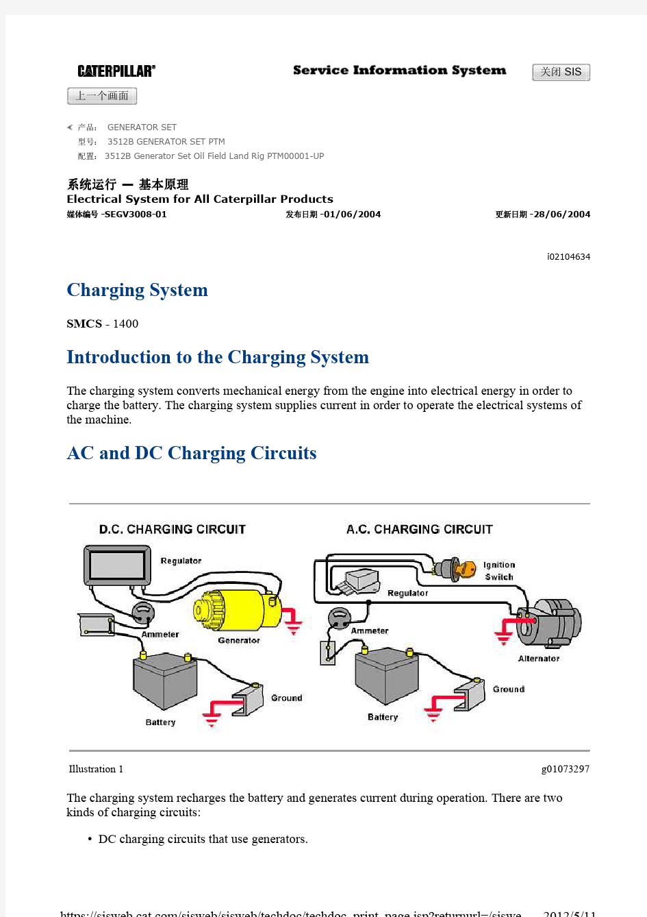
The charging system converts mechanical energy from the engine into electrical energy in order to charge the battery. The charging system supplies current in order to operate the electrical systems of the machine. AC and DC Charging Circuits
Illustration 1g01073297The charging system recharges the battery and generates current during operation.There are two kinds of charging circuits:
DC charging circuits that use generators.?
AC charging circuits that use alternators.
?
Both circuits generate an alternating current(AC). The difference in the circuits are in the way the circuits rectify the AC current to direct current (DC). DC charging circuits have a generator and a regulator.
The generator supplies the electrical power. The generator rectifies the current mechanically by using commutators and brushes.
The regulator has three functions:
?
The regulator opens the charging circuit. The regulator closes the charging circuit.
?
The regulator prevents the battery from overcharging.
?
The regulator limits the generators output to safe rates.
AC charging circuits include an alternator and a regulator. The alternator is really an AC generator. The alternator produces AC current, like the generator, but rectifies the current by using diodes. Alternators are generally more compact than generators of equal output. Alternators supply a higher current at low engine speeds.
The regulator in AC charging circuits limits the alternator voltage to a safe preset level. Transistorized models are used in many of the modern charging circuits.
Charging Circuit Operation
Illustration 2g01073299
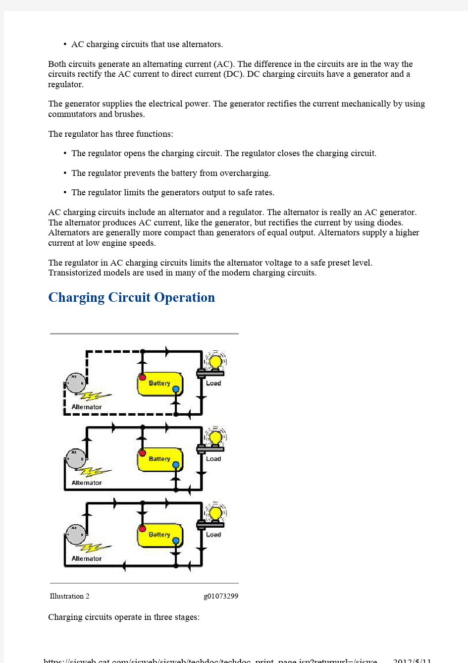
Charging circuits operate in three stages:
?
During starting, the battery supplies all the load current
?
During peak operation, the battery helps the generator (or alternator) supply current
?
During normal operation, the generator (or alternator) supplies all current and recharges the
battery
In both charging circuits, the battery starts the circuit when the battery supplies current to the starting motor in order to start the engine (Illustration 2, top diagram). The engine then drives the generator (or alternator). This produces current to take over the operation of the ignition, lights, and accessory loads in the whole system.
The center diagram (Illustration 2) shows that the battery supplies current during peak operation when the electrical loads are too high for the generator (or alternator).
Once the engine is started, the generator (or alternator)provides the current to the machine electrical systems (Illustration 2, bottom diagram). The generator supplies current as long as the engine is running above the idle speed. When the engine is at idle or stops, the battery takes over part or all of the load. However, an alternator will continue to supply current during engine idling.
Generators
Illustration 3g01073301
Generators in DC charging circuits will be covered briefly. The generator is still found on some older machines. To service this equipment, you should have a working knowledge of how the charging system functions. The majority of this lesson will focus on AC charging circuits, which have replaced DC charging circuits in the late model machines.
The generator produces electrical energy by using electromagnetic induction. Electromagnetic induction is used to generate electricity in the charging system. Electromagnetic induction occurs when there is relative movement between a conductor and a magnetic field. As the conductor cuts through the field a voltage is induced in the conductor. This voltage causes current flow when the conductor is connected to a circuit. The amount of output depends on the strength of the magnetic field, the speed at which the magnetic field is cut, and the number of conductors cutting the field. The basic generator has two components:
Armature-a rotating wire loop(conductor)
Magnetic poles-stationary magnetic field
As the armature rotates through the magnetic field of the poles, voltage is generated.The ends of the armature loop are connected to a split ring that is called a commutator. Brushes contact the commutator and wires connect the brushes to a load. Current will flow since the circuit is complete. To ensure a strong current and proper flow, wires are wound around the magnetic poles and the wires are attached to the brushes. The wiring is called the field circuit of the generator.
Illustration 4g01073303
The basic generator produces an alternating current when the armature rotates. The armature reverses the polarity of the current on each side of the loop.
During the first half of the revolution, the top of the armature side (A) cuts through the magnetic field first, while the bottom of side (B) is first to cut through the field. Current flows toward side (A) and away from side (B). The conventional theory (+ to -) gives the polarities shown (+) for (A) and (-) for (B) .
During the second half of the revolution, the top of side (B) is the leading edge, while the bottom of side (A) is leading. Now (B) is (+) while (A)is (-). The armature loop ends reverse polarity during each revolution. The result is alternating current.
Illustration 5g01073305
The commutator and brushes allow the AC current to flow to the load in the same direction. Twice during each rotation, the armature is vertical to the magnetic field. The armature loop is not passing through the field and no voltage is generated at this point. This is the static neutral point.
The commutator is split into two parts with the open areas matching the neutral point of the armature. This means that there is an air gap as the commutator passes the brushes. The other half of the commutator contacts the brushes past this point.Since the coil is in the same relative position as during the preceding one half revolution, current flow to the brush stays in the same direction. This results in direct current.
Illustration 6g01073307
Direct current systems will automatically provide more field current as generator output increases. This increase in field current will result in an increase in generator output. If the current is left unregulated, the continuous increase will result in current and voltage levels that will destroy the generator, other electrical circuits, and the battery.
The generator cannot control the amount of voltage that is produced. Therefore, an external unit that is called a voltage regulator is used in the field circuit. A voltage regulator has a shunt coil and contact points to control the strength of the magnetic field. The result is limiting the voltage that is generated.
Alternator
An alternator operates on the same principle as a generator. An alternator converts mechanical energy into electrical energy. The alternator could be called an AC generator.The difference between the generator and alternator is the way the alternator rectifies AC current to DC current. The alternator rectifies current electronically by using diodes.
Alternators are generally more compact than generators. Alternators can supply a higher current at low engine speeds. Since late model machines include many electrical accessories, the alternator can best supply the current output for the increased electrical loads.
Illustration 7g01073308
In the alternator, the magnetic field rotates inside the wire loop. This rotating magnetic field is generated by a rotor. The wire loop, which is stationary, is the conductor.
Magnetic lines of force move across the conductors. Magnetic lines induce current flow in the lines. Since the conductors are stationary, the conductors can be directly connected instead of using brushes. This reduces heat and wear.
Voltage will be induced in a conductor when a magnetic field is moved across the conductor. For example, consider a bar magnet with the magnetic field rotating inside a loop of wire. When the magnet is rotating, and with the(S) pole of the magnet is directly under the top portion of the loop and the (N)pole is directly over the bottom portion, the induced voltage will cause current to flow in the circuit in the direction shown. Since current flows from positive to negative through the external or load circuit, the end of the loop of wire that is marked (A) will be positive polarity and the end that is marked (B) will be negative polarity.
After the bar magnet has moved through one half revolution, the (N) pole will have moved directly under the top conductor and the (S) pole will have moved directly over the bottom conductor. The induced voltage will now cause current to flow in the opposite direction. The end of the loop wire that is marked (A) will become negative polarity, and the end that is marked (B) will become positive polarity. The polarity of the ends of the wire has changed. After a second one half revolution, the bar magnet will be back at the starting point where (A) is positive and (B) is negative. Consequently,current will flow through the load or through the external circuit first in one direction and then in the other direction. This is an alternating current, which is developed internally by an alternator.
How Voltage is Induced
Illustration 8g01073309
Very little voltage and current are produced with a bar magnet that is rotating inside a single loop of wire. When the loop of wire and the magnet are placed inside an iron frame, a conducting path for the magnetic lines of force is created. Since iron conducts magnetism very easily, adding the iron frame greatly increases the number of lines of force between the (N) pole and the (S)pole.
A large number of magnetic lines of force are at the center of the tip of the magnet. Therefore, a strong magnetic field exists at the center of the magnet and a weak magnetic field exists at the leading and trailing edges. This condition results when the air gap between the magnet and field frame is greater at the leading and trailing edges than at the center of the magnet.
The amount of voltage that is induced in a conductor is proportional to the number of lines of force which cut across the conductor in a given length of time. The voltage will also increase if the bar magnet turns faster because the lines of force cut across the wire in a shorter time period.
The rotating magnet in an alternator is called the rotor and the loop of wire and frame assembly is called the stator.
Illustration 9g01073310 In Illustration 9 the single loop of wire acting as a stator winding and the bar magnet acting as a rotor illustrate how an AC voltage is produced in a basic alternator. When two more separate loops of wire,
spaced 120 degrees apart, are added to the basic alternator, two more separate voltages will be produced.
When the (S) pole of the rotor is directly under the (A) conductor, the voltage at (A) will be maximum in magnitude and positive in polarity.
After the rotor has turned through 120 degrees, the (S) pole will be directly under the (B) conductor and the voltage at (B) will be maximum positive. Also 120degrees later, the voltage at (C) will be maximum positive. The peak positive voltages at (A) , (B), (C) in each loop of wire occur 120 degrees apart. These loop voltages are also shown in Illustration 9.
Illustration 10g01073311
When the ends of the loops of wire marked (A1), (B1) and (C1) are connected to the ends marked (B), (C), and (A ) respectively, a basic three-phase delta wound stator is formed (Illustration 10). The three AC voltages ( (BA), (CB) and (AC)) available from the delta wound stator are identical to the three voltages previously discussed.
Illustration 11g01073312 When the ends of the loops of wire marked (A1), (B1) and (C1) are connected together,a basic three-phase Y wound stator is formed (Illustration 11). Each of these voltages consist of the voltages in two loops of wire that are added together.Three AC voltages that are spaced 120 degrees apart are available from the Y stator.
In delta windings, each of the individual windings is connected to the end of another winding (Illustration 10). This creates parallel connections in the delta stator, which generally allows for higher current output than the Y wound stator. In the Y wound stator the windings are connected in order to form pairs of series connections (Illustration 11). The series connections generally provide higher voltages but lower current output than the delta wound stators.
The following modifications are used to increase the output of the alternator:
?
Increase the number of conductors in each of the phase windings.
?
Increase the strength of the magnetic fields.
?
Increase the speed of rotation.
Magnetic field generation
?
Current Rectification Using Y or Delta Wound Stators
Illustration 12g01073314
Even though the alternator seems complete, the current that is being generated from the alternator is still alternating. The electrical system requires direct current. In order for the output of the alternator to be of any value, the alternator must be converted from AC to DC.
The ideal device for this task is the diode. The diode is compact. The diode will conduct current in one direction only. The diode can be easily installed in the alternator housing.
Diodes are normally used in the alternator in two groups of three. Since there are three phases or windings in the alternator, three positive diodes and three negative diodes are required. In systems that require higher output, more diodes may be required.
A battery that is connected to the DC output terminal will have the energy restored as the alternator provides charging current. The blocking action of the diodes prevents the battery from discharging directly through the rectifier.
Illustration 13g01073316
The three AC voltage curves that are provided by the Y type stator have been divided into six periods. These periods are shown in Illustration 13. Each period represents one sixth of a rotor revolution, or 60 degrees.
Illustration 14g01073318 During period 1, the maximum voltage that is being induced appears across stator terminals (BA). This means the current flows from (B) to (A) in the stator winding during this period, and through the diodes as illustrated in Illustration 14.
The peak phase voltage that is developed from (B) to (A) is16 volts. This means that the potential at (B) is 0 volts and the potential at(A) is 16 volts. From the voltage curves, the phase voltage from (C) to (B) at this instant is negative 8 volts. This means that the potential at (C) is 8volts, since (C) to (B), or 8 to zero, represents a negative 8 volts. At this same time, the phase voltage from (A) to C is also negative 8 volts since (A) to(C), or 16 to 8, represents a negative 8 volts. The voltage potentials are shown in Illustration 13.
Only two of the diodes will conduct current, since these are the only diodes in which current can flow in the forward direction. The other diodes will not conduct current because these are reverse biased. The voltages that exist at the rectifier and the biasing of the diodes determine the current flow directions. These voltages are represented by the phase voltage curves in Illustration 13, which are the voltages that actually appear at the rectifier diodes. Following the same procedure for periods 2 through 6, the current flows can be determined.
Illustration 15g01073321
The voltage that is obtained from the stator-rectifier combination when connected to a battery is not perfectly flat, but is so smooth that the output may be considered to be a nonvarying DC voltage. Illustration 15 shows the voltage that is obtained from the phase voltage curves.
Illustration 16g01073323
A delta type stator that is wound to provide the same output as a Y stator will also provide a smooth voltage and current output when the stator is connected to a six diode rectifier. For explanation purposes, the three-phase voltage curves that are obtained from the basic delta connection for one rotor revolution are reproduced here, and the curves are divided into six periods.
Illustration 17g01073324
During period 1 (Illustration 17), the maximum voltage that is being developed in the Delta stator is in phase (BA). The current flow through the rectifier is exactly the same as for the Y stator since the voltage potentials on the diodes are identical. The difference between the Delta stator and the Y stator is that the Y stator conducts current through only two windings throughout one period. The delta stator conducts current through all three windings.
Phase (BA) is in parallel with phase (BC) and (CA). Since the voltage from (B ) to (A) is 16, the voltage from (B) to (C) to (A) also must be 16 because 8 volts is developed in each of these two phases ( (B) to (C) and (C) to (A). Following the same procedure for periods 2-6, the current flows can be determined.
Alternator Construction
Illustration 18g01073327
When current is passed through the coil assembly, a magnetic field is created in each of the rotor pole pieces. One set of fingers will become north poles while the other set of fingers will become south poles.
Since the rotor fingers overlap each other, many individual flux loops will be formed between the alternator north and south poles. Instead of passing one magnetic field past each winding during one revolution of the rotor, many fields will pass the windings, which will increase the output of the stator.
Since the rotor must be supplied with current to create the magnetic field, the coil assembly inside the pole piece is connected to slip rings. These slip rings are provided so that brushes can be used to provide current to the moving field. Slip rings are pressed onto the shaft and insulated from the shaft. The coil conductors are soldered to the slip rings in order to form a complete circuit that is insulated from the shaft.
Because the rotor will be spinning at high speed, the rotor must be supported by bearings. The front end of the shaft has a bearing that is mounted in the drive end housing assembly (Illustration 18).
Note: Spacers are added to place the rotor in the correct position once the alternator is assembled. This will keep the fan from hitting the housing.
Since the generation of electricity creates heat, a fan is included in order to provide a flow of air through the assembly for cooling. A pulley is attached to the end of the rotor shaft. The pulley is driven by a belt.
Illustration 19g01073328
The end housing supports the slip ring end of the rotor shaft. The end housing provides a mounting surface for the brushes, rectifier assembly, stator and regulator (if equipped). The drive end housing with the rotor and the slip ring end housing with the components are assembled as a unit. The stator is held in between. This assembly is held together with through capscrews.
The stator assembly is a laminated soft iron ring with three groups of coils or windings.One end of each stator winding is connected to a positive diode and a negative diode. The other ends of the stator windings can be connected in either a Y type stator configuration or a delta stator configuration.
The rectifier assembly converts the (AC) current to (DC) current. Three positive diodes and three negative diodes are mounted to the rectifier assembly.
The alternator is designed to provide minimal clearance between the rotor and stator, in order to maximize the effects of the magnetic field. The alternator is a compact assembly that is capable of generating high current flow in order to satisfy the needs of the electrical system.
The brushes are in contact with the copper slip rings in order to provide the necessary current for production of the magnetic field in the rotor. Since good contact is important for good conductivity, the brushes are held against the slip rings by small coil springs.
There are two brushes,which are usually contained in a brush holder assembly. This assembly can be easily attached to the slip ring end housing of the alternator.
Regulating the Alternator Output
Illustration 20g01073329
If the alternator were allowed to operate uncontrolled, the alternator would produce voltages too high to be used in the machine. This would result in damage to the components. The regulator controls alternator output.
Current output is limited by the construction of the alternator. Current output is indicated as a maximum on the housing. For example, a housing may have a listing such as 12V85A. This indicates that the maximum output is 85 amperes and the alternator is designed for a 12 volt system. The regulation circuit controls the voltage output of the alternator by changing the strength of the magnetic field that is produced by the rotor. The regulator circuit does this by controlling the amount of current that flows through the brushes to the rotor coil.
The regulator is sensitive to the voltage of the battery. The regulator is sensitive to the electrical load that is being placed on the system. The regulator can then adjust the amount of current to the rotor in order to satisfy the demand.
If the battery voltage is low and the demand from electrical accessories is high,the voltage regulator will increase the output of the alternator to charge the battery. This provides sufficient current to operate accessories. When battery voltage is high and the electrical demands are low, the voltage regulator will reduce output from the alternator.
Alternator regulators can be of three different designs:
?
Electro-mechanical (older machines)
?
Electronic external regulators
?
Electronic integral regulators
Electro-mechanical regulators can be found on some older systems. These regulators use relays to operate contact points. The double contact voltage regulator controls alternator output by regulating the amount of current flow to the rotor. Reducing current flow will reduce the strength of the magnetic field and result in lower output from the stator.
Electronic Voltage Regulators
Illustration 21g01073331
Electronic voltage regulators perform the same function as the electro-mechanical regulators. In the electronic regulator, the field circuit is switched ON and OFF by electronic circuits. These circuits controll switching transistors. These electronic devices can be switched more quickly and carry more current than the contact points in the electro-mechanical regulators. Higher output from the alternator can be obtained because of greater current flow through the field circuit.
Electronic regulators use Zener diodes as part of the voltage sensing circuit. These special diodes allow current to flow in reverse of normal flow when a specific voltage across the diode is reached. When the current flows back through the Zener diode the field transistor is turned off and current flow is stopped in the field rotor. The electronic components can switch on and off several thousand times a second. This provides very smooth, accurate control of alternator output.
Most electronic regulators are not adjustable. If the regulators do not accurately control the output of the alternator, the regulator must be replaced.
Electronic Regulator Operation at Engine Start-Up
Illustration 22g01073332 When the starter switch is turned ON, the circuit is completed (Illustration 22).Battery current flows to the starter solenoid and the starter key switch, as shown by the red lines. The key start switch directs current flow to the alternator indicator lamp and the regulator.
As the current flows into the regulator, different voltage values govern the course of the current. The voltage across resistors (R7) and (R8) is below the Zener diode critical or below the breakdown voltage. Therefore, the voltage that is felt at the base of(TR2), is the same as the voltage at the emitter. So the current cannot flow through (TR2) (as shown by the blue lines).
Thus the voltage difference in the emitter base circuit of (TR1) allows current to flow from the emitter through the base and collector. The collector current then goes on to excite the alternator field (vertical red line). At the same time, a slight amount of current flow travels to the alternator ground.
Regulator Operation During Engine Operation
Illustration 23g01073333 Regulator operation at the beginning of engine operation (Illustration 23) is similar to the engine start -up period, except that as the engine speeds up the alternator field around the rotor generates voltage in order to supply electrical loads.
However, the voltage values are still the same and transistor (TR1)still conducts the current to the alternator field as shown by the vertical red line.
Illustration 24g01073334 As the engine operates and load requirements begin to decrease, the alternator voltage increases (Illustration 24). This causes the voltage across the resistors to also increase. Then the voltage across (R7) and (R8) becomes greater than the Zener diode critical voltage. The Zener diode immediately breaks down allowing current to flow in the reverse direction. This turns on transistor (TR2) and current is able to flow through (TR2's) emitter, base and collector. When current flows through
(TR2), the voltage at the base of (TR1) is equal to or greater than the emitter, which prevents current from flowing though(TR1) to the alternator field. The field collapses,alternator output is reduced and the circuit is protected.
The system voltage then drops below the critical voltage of the Zener diode. The Zener diode stops conducting. This turns off(TR2) and turns off (TR1). Current again flows to the alternator field. This operation is repeated many times a second. The two transistors act as switches that control the voltage and alternator output.
When (TR1) turns off, the alternator field current cannot drop immediately to zero, because the rotor windings cause the current to continue to flow. Before the current reaches zero,the system voltage and the regulator start current flow again. However, the decreasing field current flow induces a high voltage which can damage the transistor.
The field discharge diode that is shown in Illustration 24prevents damage to transistor (TR1) . Internal electronic regulators
Illustration 25g01073337
Internal alternator regulators are mounted either inside or outside of the slip ring end housing of the alternator. This type of regulator eliminates the wiring harness between the alternator and regulator simplifying the system. This type of regulator is usually much smaller than other types and uses electronic circuits known as integrated circuits or ICs. ICs are miniaturized electronics with much of the circuit on one small chip. Integral regulators perform the same function as the external electronic regulators.
Some alternators with integral regulators have only one wire that is going to the regulator. This wire is the alternator output wire. The ground circuit is completed through the housing to the engine block. Current for the integral regulator is fed from the stator through a diode trio. The alternator starts charging by using the small amount of permanent magnetism in the rotor. This small amount of output is fed back into the field which increases the output. This continues until full output that is determined by the regulator is reached.
Regulator Circuits
Illustration 26g01073339 There are two basic field circuit connections for an alternator A circuit and B circuit.
An A type circuit alternator (Illustration 26) uses two insulated brushes in the alternator. One brush is connected directly to the battery, while the other brush is connected to ground with the regulator and ignition switch or relay in series. The regulator is located after the field, between the field and the alternator ground or negative diodes. Full alternator output is obtained by grounding the field windings. Some alternators have a tab in a test hole so that the field is grounded by placing a screwdriver against the tab end and the alternator frame. This type of circuit is used with integral regulators and some external electronic regulators.
Illustration 27g01073340 B type circuits use a brush that is grounded inside the alternator (Illustration27). The other brush is connected to the battery in series with the regulator and the ignition switch or the relay. In a B circuit alternator the regulator is located before the field. The current flow is usually from the regulator terminal of the alternator to the regulator. After the regulator, the current flows to the field coil in the rotor, then to ground, and finally to the negative or return diode assembly. Full alternator output is obtained by connecting the field terminal to the regulator terminal or the output terminal. Charge Indicators
燃油压力调节器 喷油器的喷油量取决于喷孔截面,喷油时间和喷油压差。ECU通过控制喷油嘴开启时间来控制喷油量,因此,在喷孔面积一定时还要保持一定的压差。 喷油压差是指输油管内燃油压力和进气歧管内气体压力的差值,而进气歧管内气压随转速和负荷(节气门开度)变化,要保持恒定的喷油压力必须根据进气管压力变化来调节燃油压力。不知道你有没有这个东西的图,我这里上不了图,就大概的讲一下:压力调节器的上方一般会有个开口用橡胶软管跟进气管连接,在内部这个开口的下方是个弹簧,弹簧下面是个膜片,膜片下面是个柱塞状的东西,堵住一个孔,这个孔就是连接回油软管的,工作时,膜片上方的压力为弹簧压力和进气压力之和,膜片下方为燃油压力,膜片上下压力相等时就会处在平衡位置,当进气管压力下降时,膜片上移回油阀开度上升,会油量上升,这样油轨中的油压就下降到原来水平。反之,气压上升时,膜片下移,回油阀开度变小,回油量变小油压就会上升到原来水平,这样油压就会控制到制造时要求的大小,也就是膜片位于平衡位置的弹力 燃油压力调节器的功用是调节至喷油器的燃油压力,使油路中的燃油压力与进气管压力之差保持常数,这样从喷油器喷出的燃油量便唯一地取决于喷油器的开启时间,使电控单元能够通过控制电脉冲宽度来精确控制喷油量。 油压调节器的构造如图5.19 所示。膜片4 将油压调节器分隔成上下两个腔。上腔有进油口1 连接燃油分配管,回油口2 与汽油箱连通。下腔通过真空接管6 与节气门后的进气管相连。当燃油压力与进气管压力之差超过预调的压力值时,膜片上方的燃油就推动膜片向下压缩弹簧,打开回油阀,超压的燃油流回燃油箱,以保持一定的燃油压力。燃油供给系统的压力与进气管压力之差由油压调节器中的弹簧5 的弹力限定,调节弹簧预紧力即可改变两者的压力差,也就是改变喷油压力。燃油压力调节器装在燃油分配管的一端,可使燃油压力调节在正常范围内(图5.20)。
常用压力传感器原理分析 振膜式谐振压力传感器 振膜式压力传感器结构如图(a)所示。振膜为一个平膜片,且与环形壳体做成整体结构,它和基座构成密封的压力测量室,被测压力 p经过导压管进入压力测量室内。参考压力室可以通大气用于测量表压,也可以抽成真空测量绝压。装于基座顶部的电磁线圈作为激振源给膜片提供激振力,当激振 频率与膜片固有频率一致时,膜片产生谐振。没有压力时,膜片是平的,其谐振频率为 f0;当有压力作用时,膜片受力变形,其张紧力增加,则相应的谐振频率也随之增加,频率随压力变化且为单值函数关系。 在膜片上粘贴有应变片,它可以输出一个与谐振频率相同的信号。此信号经放大器放大后,再反馈给激振线圈以维持膜片的连续振动,构成一个闭环正反馈自激振荡系统。如图(b)所示 压电式压力传感器 某些电介质沿着某一个方向受力而发生机械变形(压缩或伸长)时,其内部将发生极化现象,而在其某些表面上会产生电荷。当外力去掉后,它又会重新回到不带电 的状态,此现象称为“压电效应”。常用的压电材料有天然的压电晶体(如石英晶体)和压电陶瓷(如钛酸钡)两大类,它们的压电机理并不相同,压电陶瓷是人造 多晶体,压电常数比石英晶体高,但机械性能和稳定性不如石英晶体好。它们都具有较好特性,均是较理想的压电材料。 压电式压力传感器是利用压电材料的压电效应将被测压力转换为电信号的。由压电材料制成的压电元件受到压力作用时产生的电荷量与作用力之间呈线性关系: Q=kSp 式中 Q为电荷量;k为压电常数;S为作用面积;p为压力。通过测量电荷量可知被测压力大小。 图1为一种压电式压力传感器的结构示意图。压电元件夹于两个弹性膜片之间,压电元件的一个侧面与膜片接触并接地,另一侧面通过引线将电荷量引出。被测压力 均匀作用在膜片上,使压电元件受力而产生电荷。电荷量一般用电荷放大器或电压放大器放大,转换为电压或电流输出,输出信号与被测压力值相对应。 除在校准用的标准压力传感器或高精度压力传感器中采用石英晶体做压电元件外,一般压电式压力传感器的压电元件材料多为压电陶瓷,也有用高分子材料(如聚偏二氟乙稀)或复合材料的合成膜的。
CT过电压保护器的功能 1、正常工作时,流入保护器的电流不超过0.1mA,不影响CT正常工作。 2、当A(或B、C),N两端电压超过150V时RCT6-1D短接A(或B、C、),N。 3、继电器的接点容量大于15A。所以故障时,能使CT二次侧可靠短路。 4、继电器接点具有保持功能,按压“复位”按钮,才能解除保护。 5、若是在停电状态下解除了故障,掉电后装置自动复位。 6、装置提供一对转换接点。可接各种声光报警器或提供给综合保护装置使信息远传。当保护动作时,常开闭合,常闭打开。 CT过电压保护器的接线原理 一般情况下,互感器均连接在A、B、C三相上,少数连接在两相上,个别连接在一相上。绝大多数均为星形连接,少数三角形连接。本产品电流互感器保护器为二次绕组星形连接。二次绕组A、B、C对应连接在保护器为A、B、C接线端子上。A、B、C三相二次中心点(虚地N)连接在保护器的N接线端子上。 若只用A、C绕组,B相可以不接线,不会影响保护器正常工作。 交流220V50Hz电源接入保护器供内部电器元件用。三根无源信号线引出供用户使用。外接交流或直流均可。例如,公共端与常闭线连接绿色信号灯,亮灯时表示保护器正常工作。公共端和常开线连接红色灯或报警器,工作时表示保护器检测到某二次绕组有开路故障。 艾驰商城是国内最专业的MRO工业品网购平台,正品现货、优势价格、迅捷配送,是一站式采购的工业品商城!具有10年工业用品电子商务领域研究,以强大的信息通道建设的优势,以及依托线下贸易交易市场在工业用品行业上游供应链的整合能力,为广大的用户提供了传感器、图尔克传感器、变频器、断路器、继电器、PLC、工控机、仪器仪表、气缸、五金工具、伺服电机、劳保用品等一系列自动化的工控产品。 如需进一步了解相关仪器仪表产品的选型,报价,采购,参数,图片,批发等信息,请关注艾驰商城。https://www.doczj.com/doc/1b15615445.html,/
一、电压比较器原理 电压比较器是集成运放非线性应用电路,常用于各种电子设备中,那么什么是电压比较器呢? 它将一个模拟量电压信号和一个参考固定电压相比较,在二者幅度相等的附近,输出电压将产生跃变,相应输出高电平或低电平。比较器可以组成非正弦波形变换电路及应用于模拟与数字信号转换等领域。 图1所示为一最简单的电压比较器,UR为参考电压,加在运放的同相的输入端,输入电压ui加在反相的输入端。 图1电压比较器原理图(a)及传输特性(b) (a)电路图 (b)传输特性当ui<U R时,运放输出高电平,稳压管Dz反向稳压工作。输出端电位被其箝位在稳压管的稳定电压U Z,即 u O=U Z 当ui>U R时,运放输出低电平,DZ正向导通,输出电压等于稳压管的正向压降U D,即 uo=-U D 因此,以U R为界,当输入电压ui变化时,输出端反映出两种状态,高电位和低电位。 表示输出电压与输入电压之间关系的特性曲线,称为传输特性。图1(b)为(a)图比较器的传输特性。 常用的电压比较器有过零电压比较器、具有滞回特性的过零比较器、滞回电压比较器,窗口(双限)电压比较器。 二、集成电压比较器简介 作用:可将模拟信号转换成二值信号,即只有高电平和低电平两种状态的离散信号。应用:作为模拟电路和数字电路的接口电路。 特点:比集成运放的开环增益低,失调电压大,共模抑制比小;但其响应速度快,传输延迟时间短,而且不需外加限幅电路就可直接驱动TTL、CMOS和ECL等集成数字电路;有些芯片带负载能力很强,还可直接驱动继电器和指示灯(例如LM311)。 三、电压比较器的应用 电压比较器(以下简称比较器)是一种常用的集成电路。它可用于报警器电路、自动控制电路、测量技术,也可用于V/F变换电路、A/D变换电路、高速采样电路、电源电压监测电路、振荡器及压控振荡器电路、过零检测电路等。本文主要介绍其基本概念、工作原理及典型工作电路,并介绍一些常用的电压比较器。 电压比较器是对两个模拟电压比较其大小(也有两个数字电压比较的,这里不介绍),并判断出其中哪一个电压高,如图1所示。图1(a)是比较器,它有两个输入端:同相输入端(“+”端) 及反相输入端(“-”端),有一个输出端Vout(输出电平信号)。另外有电源V+及地(这是个单电源比较器),同相端输入电压V A,反相端输入V B。V A和V B的变化如图1(b)所示。
(1) 1 dR d R dA A 四种压力传感器的基本工作原理及特点 一:电阻应变式传感器 1 1电阻应变式传感器定义 被测的动态压力作用在弹性敏感元件上, 使它产生变形,在其变形的部位粘 贴有电阻应变片,电阻应变片感受动态压力的变化,按这种原理设计的传感器称 为电阻应变式压力传感器。 1.2电阻应变式传感器的工作原理 电阻应变式传感器所粘贴的金属电阻应变片主要有丝式应变片与箔式应变片 箔式应变片是以厚度为0.002―― 0.008mm 的金属箔片作为敏感栅材料,,箔 栅宽度为0.003――0.008mm 。丝式应变片是由一根具有高电阻系数的电阻丝 (直 径0. 015--0. 05mm ),平行地排成栅形(一般2――40条),电阻值60――200 ?, 通常为 120 ?,牢贴在薄纸片上,电阻纸两端焊有引出线,表面覆一层薄纸,即 制成了纸基的电阻丝式应变片。测量时,用特制的胶水将金属电阻应变片粘贴于 待测的弹性敏感元件表面上,弹性敏感元件随着动态压力而产生变形时, 电阻片 也跟随变形。如下图所示。B 为栅宽,L 为基长。 I 绘式应吏片 b )笹式应变片 材料的电阻变化率由下式决定:
式中; R—材料电阻2
3 —材料电阻率 由材料力学知识得; K —金属电阻应变片的敏感度系数 式中K 对于确定购金属材料在一定的范围内为一常数,将微分 dR 、dL 改写成增 量出、/L,可得 由式(2)可知,当弹性敏感元件受到动态压力作用后随之产生相应的变形 而形应变值可由丝式应变片或箔式应变片测出,从而得到了 ZR 的变化,也就得 到了动态压力的变化,基于这种应变效应的原理实现了动态压力的测量。 1.3电阻应变式传感器的分类及特点 「测低压用的膜片式压力传感器 常用的电阻应变式压力传感器包括彳测中压用的膜片一一应变筒式压力传感器 -测高压用 的应变筒式压力传感器 1.3.1膜片一一应变筒式压力传感器的特点 该传感器的特点是具有 较高的强度和抗冲击稳定性,具有优良的静态特性、 动态特性和较高的自震频率,可达30khz 以上,测量的上限压力可达到9.6mp a 。 适于测量高频脉动压力,又加上强制水冷却。也适于高温下的动态压力测量,如 火箭发动机的压力测量,内燃机、压气机等的压力测量。 1.3.2膜片式应变压力传咸器的特点 A 这种膜片式应变压力传感器不宜测量较大的压力,当变形大时,非线性 较大。但小压力测量中由于变形很小,非线性误差可小于 0.5%,同时又有较高 的灵敏度,因此在冲击波的测量中,国内外都用过这种膜片式压力传感器。 B 这种传感器与膜片一应变筒式压力传感器相比, 自振频率较低,因此在低dR "R [(1 2 ) C(1 2 )]
以下是电源系统SPD选择的要点: 欧阳学文 1、根据被保护线路制式,例如:单相220V、三相 220/380V TNC/TNS/TT等,选择合适制式SPD 2、根据被保护设备的耐冲击电压水平,选择SPD的电压保护水平Up。一般终端设备的耐冲击电压1.5kV,具体可参照GB 503435.4。Up值小于其耐冲击电压即可。 3、根据线路引入方式,有无因直击雷击中而传到雷电流的风险,选择一级或者二级SPD。一级SPD是有雷电流泄放参数的10/350波形的。 4、根据GB 500576.3.4里的分流计算,计算线路所需的泄放电流强度,选择合适放电能力的SPD,需要SPD标称放电电流参数大于线路的分流电涌电流即可。 至于型号,不同厂家型号不一,没什么参考价值。建议选择知名品牌,现在防雷市场鱼龙混杂,不要贪图便宜而使用劣质产品。 浪涌保护器设计原理、特性、运用范畴 设计原理
在最常见的浪涌保护器中,都有一个称为金属氧化物变阻器(Metal Oxide Varistor,MOV)的元件,用来转移多余的电压。如下图所示,MOV将火线和地线连接在一起。MOV由三部分组成:中间是一根金属氧化物材料,由两个半导体连接着电源和地线。 这些半导体具有随着电压变化而改变的可变电阻。当电压低于某个特定值时,半导体中的电子运动将产生极高的电阻。反之,当电压超过该特定值时,电子运动会发生变化,半导体电阻会大幅降低。如果电压正常,MOV会闲在一旁。而当电压过高时,MOV可以传导大量电流,消除多余的电压。随着多余的电流经MOV转移到地线,火线电压会恢复正常,从而导致MOV的电阻再次迅速增大。按照这种方式,MOV仅转移电涌电流,同时允许标准电流继续为与浪涌保护器连接的设备供电。打个比方说,MOV的作用就类似一个压敏阀门,只有在压力过高时才会打开。 另一种常见的浪涌保护装置是气体放电管。这些气体放电管的作用与MOV相同——它们将多余的电流从火线转移到地线,通过在两根电线之间使用惰性气体作为导体实现
减压阀是气动调节阀的一个必备配件,主要作用是将气源的压力减压并稳定到一个定值,以便于调节阀能够获得稳定的气源动力用于调节控制。 1.调节手柄; 2.调压弹簧; 3.溢流阀; 4.膜片; 5.阀杆; 6.反馈导管; 7.进气阀门; 8.复位弹簧 上图所示为一种常用的直动式减压阀结构。 压力为P1的压缩空气,由左端输入经进气阀门节流后,压力降为P2输出。P2的大小可由调压弹簧2进行调节。若顺时针旋转调节手柄,调压弹簧被压缩,推动膜片和阀杆下移,进气阀门打开,在输出口有气压输出。同时,输出气压经反馈导管作用在膜片上产生向上的推力。该推力与调压弹簧作用力相平衡时,阀便有稳定的压力输出。 若输出压力超过调定值,则膜片离开平衡位置而向上变形,使得溢流阀打开,多余的空气经溢流口排入大气。当输出压力降至调定值时,溢流阀关闭,膜片上的受力保持平衡状态。若逆时针放置手柄,调压弹簧放松,作用在膜片上的气压力大于弹簧力,溢流阀打开,输出压力降低直到为零。台湾DPC气动提醒您,反馈导管的作用是提高减压阀的稳压精度。另外,能改善减压阀的动
态性能,当负载突然改变或变化不定时,反馈导管起着阻尼作用,避免振荡现象发生。 若输入压力瞬时升高,输出将随之升高,使膜片气室内压力升高,在膜片上产生的推力相应增大,此推力破坏了原来力的平衡,使膜片向上移动,有少部分气流经溢流孔、排气孔排出。在膜片上移的同时,因复位弹簧的作用,使阀芯也向上移动,关小进气阀口,节流作用加大,使输出压力下降,直至达到新的平衡为止,输出压力基本又回到原来值。 若输入压力瞬时下降,输出压力也下降、膜片下移,阀芯随之下移,进气阀口开大,节流作用减小,使输出压力也基本回到原来值。逆时针旋转旋钮。使调节弹簧放松,气体作用在膜片上的推力大于调压弹簧的作用力,膜片向上曲,靠复位弹簧的作用关闭进气阀口。再旋转旋钮,进气阀芯的顶端与溢流阀座将脱开,膜片气室中的压缩空气便经溢流孔、排气孔排出,使阀处于无输出状态。 二、减压阀的基本性能 (1)?调压范围:它是指减压阀输出压力P2的可调范围,在此范围内要求达到规定的精度。调压范围主要与调压弹簧的刚度有关。 (2)?压力特性:它是指流量g为定值时,因输入压力波动而引起输出压力波动的特性。输出压力波动越小,减压阀的特性越好。
压力传感器是压力检测系统中的重要组成部分,由各种压力敏感元件将被测压力信号转换成容易测量的电 信号作输出,给显示仪表显示压力值,或供控制和报警使用。 压力传感器的种类繁多,如压阻式压力传感器、应变式压力传感器、压电式压力传感器、电容式压力传感 器、压磁式压力传感器、谐振式压力传感器及差动变压器式压力传感器,光纤压力传感器等。 一、压阻式压力传感器 固体受力后电阻率发生变化的现象称为压阻效应。压阻式压力传感器是基于半导体材料(单晶硅)的压阻效应原理制成的传感器,就是利用集成电路工艺直接在硅平膜片上按一定晶向制成扩散压敏电阻,当硅膜片 受压时,膜片的变形将使扩散电阻的阻值发生变化。 压阻式具有极低的价格和较高的精度以及较好的线性特性。 1、压阻式压力传感器基本介绍 压阻式传感器有两种类型:一种是利用半导体材料的体电阻做成粘贴式应变片,称为半导体应变片,因此 应变片制成的传感器称为半导体应变式传感器,另一种是在半导体材料的基片上用集成电路工艺制成的扩 散电阻,以此扩散电阻的传感器称为扩散型压阻传感器。 半导体应变式传感器半导体应变式传感器的结构形式基本上与电阻应变片传感器相同,也是由弹性敏感元件等三部分组成,所不同的是应变片的敏感栅是用半导体材料制成。半导体应变片与金属应变片相比,最 突出的优点是它的体积小而灵敏高。它的灵敏系数比后者要大几十倍甚至上百倍,输出信号有时不必放大 即可直接进行测量记录。此外,半导体应变片横向效应非常小,蠕变和滞后也小,频率响应范围亦很宽, 从静态应变至高频动态应变都能测量。由于半导体集成化制造工艺的发展,用此技术与半导体应变片相结 合,可以直接制成各种小型和超小型半导体应变式传感器,使测量系统大为简化。但是半导体应变片也存 在着很大的缺点,它的电阻温度系统要比金属电阻变化大一个数量级,灵敏系数随温度变化较大它的应变 —电阻特性曲线性较大,它的电阻值和灵敏系数分散性较大,不利于选配组合电桥等等。 扩散型压阻式传感器扩散型压阻传感器的基片是半导体单晶硅。单晶硅是各向异性材料,取向不同时特性不一样。因此必须根据传感器受力变形情况来加工制作扩散硅敏感电阻膜片。 利用半导体压阻效应,可设计成多种类型传感器,其中压力传感器和加速度传感器为压阻式传感器的基本 型式。 硅压阻式压力传感器由外壳、硅膜片(硅杯)和引线等组成。硅膜片是核心部分,其外形状象杯故名硅杯,在硅膜上,用半导体工艺中的扩散掺杂法做成四个相等的电阻,经蒸镀金属电极及连线,接成惠斯登电桥 再用压焊法与外引线相连。膜片的一侧是和被测系数相连接的高压腔,另一侧是低压腔,通常和大气相连,也有做成真空的。当膜片两边存在压力差时,膜片发生变形,产生应力应变,从而使扩散电阻的电阻值发 生变化,电桥失去平衡,输出相对应的电压,其大小就反映了膜片所受压力差值。
过电压保护器防雷原理解析 防雷器(Surge protection Device)是电子设备雷电防护中不可缺少的一种装置,过去常称为“避雷器”或“过电压保护器”英文简写为SPD。防雷器的作用是把窜入电力线、信号传输线的瞬时过电压限制在设备或系统所能承受的电压范围内,或将强大的雷电流泄流入地,保护被保护的设备或系统不受冲击而损坏。 防雷器元件从响应特性看,有软硬两种。属于硬响应特性的放电元件有火花间隙(基于斩弧技术的角型火花隙和同轴放电火花隙)和气体放电管,属于软响应特性的放电元件有金属氧化物压敏电阻和瞬态抑制二极管。这些元件的区别在于放电能力、响应特性和残压,避雷器就是利用它们不同的优缺点,扬长避短,组合成各种避雷器,保护电路。 二、SPD的基本元器件及其工作原理: 放电间隙(又称保护间隙): 它一般由暴露在空气中的两根相隔一定间隙的金属棒组成,其中一根金属棒与所需保护设备的电源相线L1或零线(N)相连,另一根金属棒与接地线(PE)相连接,当瞬时过电压袭来时,间隙被击穿,把一部分过电压的电荷引入大地,避免了被保护设备上的电压升高。这种放电间隙的两金属棒之间的距离可按需要调整,结构较简单,其缺点时灭弧性能差。改进型的放电间隙为角型间隙,它的灭弧功能较前者为好,它是靠回路的电动力F作用以及热气流的上升作用而使电弧熄灭的。 2.气体放电管: 它是由相互离开的一对伶阴板封装在充有-定的惰性气体(Ar)的玻璃管或陶瓷管内组成的。为了提高放电管的触发概率,在放电管内还有助触发剂。这种充气放电管有二极型的,也有三极型的, 气体放电管的技术参数主要有:直流放电电压Udc;冲击放电电压Up(- -般情况下Up=(2~ 3)Udc;工频而授电流In;冲击而授电流lp;绝缘电阻R(》109);极间电容(1- 5PF) 气体放电管可在直流和交流条件下使用,其所选用的直流放电电压Udc分别如下:在
比较器原理,比较器的工作原理 电压比较器(以下简称比较器)是一种常用的集成电路。它可用于报警器电路、自动控制电路、测量技术,也可用于V/F变换电路、A/D变换电路、高速采样电路、电源电压监测电路、振荡器及压控振荡器电路、过零检测电路等。本文主要介绍其基本概念、工作原理及典型工作电路,并介绍一些常用的电压比较器。 什么是电压比较器以其原理 简单地说,电压比较器是对两个模拟电压比较其大小(也有两个数字电压比较的,这里不介绍),并判断出其中哪一个电压高,如图1所示。图1(a)是比较器,它有两个输入端:同相输入端(“+”端)及反相输入端(“-”端),有一个输出端Vout(输出电平信号)。另外有电源V+及地(这是个单电源比较器),同相端输入电压VA,反相端输入VB。VA和VB的变化如图1(b)所示。在时间0~t1时,VA>VB;在t1~t2时,VB>VA;在t2~t3时,VA>VB。在这种情况下,Vout的输出如图1(c)所示:VA>VB时,Vout输出高电平(饱和输出);VB>VA时,Vout输出低电平。根据输出电平的高低便可知道哪个电压大。 比较器原理:对两个或多个数据项进行比较,以确定它们是否相等,或确定它们之间的大小关系及排列顺序称为比较。能够实现这种比较功能的电路或装置称为比较器。比较器是将一个模拟电压信号与一个基准电压相比较的电路。比较器的两路输入为模拟信号,输出则为二进制信号,当输入电压的差值增大或减小时,其输出保持恒定。 比较器两大类别 1.模拟比较器 将模拟量与一标准值进行比较,当高于该值时,输出高(或低)电平.反之,则输出低(或高)电平.例如,将一温度信号接于运放的同相端,反相端接一电压基准(代表某一温度),当温度高于基准值时,运放输出高电平,控制加热器关闭,反之当温度信号低于基准值时,运放输出低电平,将加热器接通.这一运放就是一个简单的比较器,因为输入与输出同相,称为同相比较器..有的模拟比较器具有迟滞回线,称为迟滞比较器,用这种比较器,有助于消除寄生在信号上的干扰. 2.数字比较器 用来比较二组二进制数是否相同,相同时输出(或低)高电平,反之,则输出相反的电平. 最简单的数字比较器是一位二进制数比较器,是一个异或门(或同或门). 比较器的工作原理 比较器是由运算放大器发展而来的,比较器电路可以看作是运算放大器的一种应用电路。由于比较器电路应用较为广泛,所以开发出了专门的比较器集成电路。 图4(a)由运算放大器组成的差分放大器电路,输入电压VA经分压器R2、R3分压后接在同相端,VB通过输入电阻R1接在反相端,RF为反馈电阻,若不考虑输入失调电压,则其输出电压Vout与VA、VB及4个电阻的关系式为:Vout= (1+RF/R1)·R3/(R2+R3)VA-(RF/R1)VB。若R1=R2,R3=RF,则Vout=RF/R1(VA-VB),RF/R1为放大器的增益。当R1=R2=0(相当于R1、R2短路),R3=RF=∞(相当于R3、R F开路)时,Vout=∞。增益成为无穷大,其电路图就形成图4(b)的样子,差分放大器处于开环状态,它就是比较器电路。实际上,运放处于开环状态时,其增益并非无穷大,而Vout输出是饱和电压,它小于正负电源电压,也不可能是无穷大。
压力传感器 压力传感器是工业实践、仪器仪表控制中最为常用的一种传感器,并广泛应用于各种工业自控环境,涉及水利水电、铁路交通、生产自控、航空航天、军工、石化、油井、电力、船舶、机床、管道等众多行业。 力学传感器的种类繁多,如电阻应变片压力传感器、半导体应变片压力传感器、压阻式压力传感器、电感式压力传感器、电容式压力传感器、谐振式压力传感器及电容式加速度传感器等。但应用最为广泛的是压阻式压力传感器,它具有极低的价格和较高的精度以及较好的线性特性。下面我们主要介绍这类传感器。 1、压阻式压力传感器原理与应用: 压阻式压力传感器是利用单晶硅材料的压阻效应和集成电路技术制成的传感器。压阻式传感器常用于压力、拉力、压力差和可以转变为力的变化的其他物理量(如液位、加速度、重量、应变、流量、真空度)的测量和控制。 压阻效应 当力作用于硅晶体时,晶体的晶格产生变形,使载流子从一个能谷向另一个能谷散射,引起载流子的迁移率发生变化,扰动了载流子纵向和横向的平均量,从而使硅的电阻率发生变化。这种变化随晶体的取向不同而异,因此硅的压阻效应与晶体的取向有关。硅的压阻效应不同于金属应变计,前者电阻随压力的变化主要取决于电阻率的变化,后者电阻的变化则主要取决于几何尺寸的变化(应变),而且前者的灵敏度比后者大50~100倍。 压阻式压力传感器结构 压阻式压力传感器采用集成工艺将电阻条集成在单晶硅膜片上,制成硅压阻芯片,并将此芯片的周边固定封装于外壳之内,引出电极引线。压阻式压力传感器又称为固态压力传感器,它不同于粘贴式应变计需通过弹性敏感元件间接感受外力,而是直接通过硅膜片感受被测压力的。硅膜片的一面是与被测压力连通的高压腔,另一面是与大气连通的低压腔。硅膜片一般设计成周边固支的圆形,直径与厚度比约为20~60。在圆形硅膜片(N型)定域扩散4条P杂质电阻条,并接成全桥,其中两条位于压应力区,另两条处于拉应力区,相对于膜片中心对称。硅柱形敏感元件也是在硅柱面某一晶面的一定方向上扩散制作电阻条,两条受拉应力的电阻条与另两条受压应力的电阻条构成全桥。
电涌保护器(Surge protection Device)是电子设备雷电防护中不可缺少的一种装置,过去常称为“避雷器”或“过电压保护器”英文简写为SPD。电涌保护器的作用是把窜入电力线、信号传输线的瞬时过电压限制在设备或系统所能承受的电压范围内,或将强大的雷电流泄流入地,保护被保护的设备或系统不受冲击而损坏。 电涌保护器的类型和结构按不同的用途有所不同,但它至少应包含一个非线性电压限制元件。用于电涌保护器的基本元器件有:放电间隙、充气放电管、压敏电阻、抑制二极管和扼流线圈等。 一、SPD的分类: 1、按工作原理分: 1.开关型:其工作原理是当没有瞬时过电压时呈现为高阻抗,但一旦响应雷电瞬时过电压时,其阻抗就突变为低值,允许雷电流通过。用作此类装置时器件有:放电间隙、气体放电管、闸流晶体管等。 2.限压型:其工作原理是当没有瞬时过电压时为高阻扰,但随电涌电流和电压的增加其阻抗会不断减小,其电流电压特性为强烈非线性。用作此类装置的器件有:氧化锌、压敏电阻、抑制二极管、雪崩二极管等。 3.分流型或扼流型 分流型:与被保护的设备并联,对雷电脉冲呈现为低阻抗,而对正常工作频率呈现为高阻抗。 扼流型:与被保护的设备串联,对雷电脉冲呈现为高阻抗,而对正常的工作频率呈现为低阻抗。 用作此类装置的器件有:扼流线圈、高通滤波器、低通滤波器、1/4波长短路器等。 按用途分:(1)电源保护器:交流电源保护器、直流电源保护器、开关电源保护器等。 (2)信号保护器:低频信号保护器、高频信号保护器、天馈保护器等。 二、SPD的基本元器件及其工作原理: 1.放电间隙(又称保护间隙): 它一般由暴露在空气中的两根相隔一定间隙的金属棒组成(如图15a),其中一根金属棒与所需保护设备的电源相线L1或零线(N)相连,另一根金属棒与接地线(PE)相连接,当瞬时过电压袭来时,间隙被击穿,把一部分过电压的电荷引入大地,避免了被保护设备上的电压升高。这种放电间隙的两金属棒之间的距离可按需要调整,结构较简单,其缺点时灭弧性能差。改进型的放电间隙为角型间隙,它的灭弧功能较前者为好,它是*回路的电动力F 作用以及热气流的上升作用而使电弧熄灭的。 2.气体放电管: 它是由相互离开的一对冷阴板封装在充有一定的惰性气体(Ar)的玻璃管或陶瓷管内组成的。为了提高放电管的触发概率,在放电管内还有助触发剂。这种充气放电管有二极型的,也有三极型的, 气体放电管的技术参数主要有:直流放电电压Udc;冲击放电电压Up(一般情况下Up≈(2~3)Udc;工频而授电流In;冲击而授电流Ip;绝缘电阻R(>109Ω);极间电容(1-5PF) 气体放电管可在直流和交流条件下使用,其所选用的直流放电电压Udc分别如下:在直流条件下使用:Udc≥1.8U0(U0为线路正常工作的直流电压) 在交流条件下使用:U dc≥1.44Un(Un为线路正常工作的交流电压有效值) 3.压敏电阻: 它是以ZnO为主要成分的金属氧化物半导体非线性电阻,当作用在其两端的电压达到一定数值后,电阻对电压十分敏感。它的工作原理相当于多个半导体P-N的串并联。压敏电阻的特点是非线性特性好(I=CUα中的非线性系数α),通流容量大(~2KA/cm2),常
电压比较器工作原理及应用实例 时间:2011-11-24来源:作者:方佩敏 来源:https://www.doczj.com/doc/1b15615445.html, 本文主要介绍电压比较器基本概念、工作原理及典型工作电路,并介绍一些常用的电压比较器。 电压比较器(以下简称比较器)是一种常用的集成电路。它可用于报警器电路、自动控制电路、测量技术,也可用于V/F变换电路、A/D变换电路、高速采样电路、电源电压监测电路、振荡器及压控振荡器电路、过零检测电路等。 什么是电压比较器 简单地说,电压比较器是对两个模拟电压比较其大小(也有两个数字电压比较的,这里不介绍),并判断出其中哪一个电压高,如图1所示。图1(a)是比较器,它有两个输入端:同相输入端(“+”端)及反相输入端(“-”端),有一个输出端Vout(输出电平信号)。另外有电源V+及地(这是个单电源比较器),同相端输入电压VA,反相端输入VB。VA和VB的变化如图1(b)所示。在时间0~t1时,VA>VB;在t1~t2时,VB>VA;在t2~t3时,VA>VB。在这种情况下,Vout 的输出如图1(c)所示:VA>VB时,Vout输出高电平(饱和输出);VB>VA时,Vout 输出低电平。根据输出电平的高低便可知道哪个电压大。 如果把VA输入到反相端,VB输入到同相端,VA及VB的电压变化仍然如图1(b)所示,则Vout输出如图1(d)所示。与图1(c)比较,其输出电平倒了一下。输出电平变化与VA、VB的输入端有关。 图2(a)是双电源(正负电源)供电的比较器。如果它的VA、VB输入电压如图
1(b)那样,它的输出特性如图2(b)所示。VB>VA时,Vout输出饱和负电压。 如果输入电压VA与某一个固定不变的电压VB相比较,如图3(a)所示。此VB称为参考电压、基准电压或阈值电压。如果这参考电压是0V(地电平),如图3(b)所示,它一般用作过零检测。 比较器的工作原理 比较器是由运算放大器发展而来的,比较器电路可以看作是运算放大器的一种应用电路。由于比较器电路应用较为广泛,所以开发出了专门的比较器集成电路。 图4(a)由运算放大器组成的差分放大器电路,输入电压VA经分压器R2、R3分压后接在同相端,VB通过输入电阻R1接在反相端,RF为反馈电阻,若不考虑输入失调电压,则其输出电压Vout与VA、VB及4个电阻的关系式为: Vout=(1+RF/R1)·R3/(R2+R3)VA-(RF/R1)VB。若R1=R2,R3=RF,则 Vout=RF/R1(VA-VB),RF/R1为放大器的增益。当R1=R2=0(相当于R1、R2短路),R3=RF=∞(相当于R3、RF开路)时,Vout=∞。增益成为无穷大,其电路图就形成图4(b)的样子,差分放大器处于开环状态,它就是比较器电路。实际上,运放处于开环状态时,其增益并非无穷大,而Vout输出是饱和电压,它小于正负电源电压,也不可能是无穷大。
压力变送器的工作原理 压力变送器的工作原理 压力变送器主要由测压元件传感器(也称作压力传感器)、放大电路和支持结构件三类组成。它能将测压元件传感器测量到的气体、液体等物理压力参数变化转换成电信号(如4~20mA等),以提供指示报警仪、记载仪、调理器等二次仪表进行显示、指示和调整。 压力变送器用于测量液体、气体或蒸汽的液位、密度和压力,然后转换为成4~20mA 信号输出。 压差变送器也称差压变送器,主要由测压元件传感器、模块电路、显示表头、表壳和过程连接件等组成。它能将接收的气体、液体等压力差信号转变成标准的电流电压信号,以供给指示报警仪、记录仪、调节器等二次仪表进行测量、指示和过程调节。 差压变送器根据测压范围可分成一般压力变送器(0.001MPa~20MPA)和微差压变送器(0~30kPa)两种。 差压变送器的测量原理是:流程压力和参考压力分别作用于集成硅压力敏感元件的两端,其差压使硅片变形(位移很小,仅μm级),以使硅片上用半导体技术制成的全动态惠斯登电桥在外部电流源驱动下输出正比于压力的mV级电压信号。由于硅材料的强性极佳,所以输出信号的线性度及变差指标均很高。工作时,压力变送器将被测物理量转换成mV级的 电压信号,并送往放大倍数很高而又可以互相抵消温度漂移的差动式放大器。放大后的信号经电压电流转换变换成相应的电流信号,再经过非线性校正,最后产生与输入压力成线性对应关系的标准电流电压信号。 压力传感器工作原理 压力传感器是工业实践中最为常用的一种传感器,其广泛应用于各种工业自控环境,涉及水利水电、铁路交通、智能建筑、生产自控、航空航天、军工、石化、油井、电力、船舶、机床、管道等众多行业,下面就简单介绍一些常用传感器原理及其应用 1 、应变片压力传感器原理与应用 力学传感器的种类繁多,如电阻应变片压力传感器、半导体应变片压力传感器、压阻式
实验十电压比较器的安装与测试 一.实验目的 1.了解电压比较器的工作原理。 2.安装和测试四种典型的比较器电路:过零比较器、电平检测器、滞回比较器和窗口比较器。 二.预习要求 1.预习过零比较器、电平检测器、滞回比较器和窗口比较器的工作原理。 2.预习使用示波器测量信号波形和电压传输特性的方法。 三.实验原理 电压比较器的基本功能是能对两个输入电压的大小进行比较,判断出其中那一个比较大。比较的结果用输出电压的高和低来表示。电压比较器可以采用专用的集成比较器,也可以采用运算放大器组成。由集成运算放大器组成的比较器,其输出电平在最大输出电压的正极限值和负极限值之间摆动,当要和数字电路相连接时,必须增添附加电路,对它的输出电压采取箝位措施,使它的高低输出电平,满足数字电路逻辑电平的要求。 下面讨论几种常见的比较器电路。 基本过零比较器(零电平比较器) 过零比较器主要用来将输入信号与零电位进行比较,+15V 以决定输出电压的极性。电路如图1所示:u i 2 7 放大器接成开环形式,信号u i从反向端输入,同μA7416u o 相端接地。当输入信号u i< 0时,输出电压u o为正极限34 值U OM;由于理想运放的电压增益A u→∞,故当输-15V 入信号由小到大,达到u i = 0 时,即u -= u + 的时刻, 输出电压u o 由正极限值U OM 翻转到负极限值-U OM。图 1 反向输入过零比较器 当u i >0时输出u o为负极限值-U OM。因此,输出翻转的临界条件是u + = u - = 0。 即:+U OM u i< 0 u o = (1) -U OM u i >0 其传输特性如图2(a)所示。所以通过该电路输出的电压值,就可以鉴别输入信号电压u i是大于零还是小于零,即可用做信号电压过零的检测器。
冷凝压力调节阀的工作原理 冷凝压力调节阀用于调理介质的流量、压力和液位。依据调理部位旌旗灯号,主动节制阀门的开度,然后到达介质流量、压力和液位的调理。冷凝压力调节阀分电动冷凝压力调节阀、气动冷凝压力调节阀和液动冷凝压力调节阀等。 冷凝压力调节阀由电动执行机构或气动执行机构和冷凝压力调 节阀两局部构成。冷凝压力调节阀凡间分为纵贯单座式冷凝压力调节阀和纵贯双座式冷凝压力调节阀两种,后者具有流畅才能大、不服衡办小和操作不变的特点,所以凡间特殊合用于大流量、高压降和走漏少的场所。 流畅才能Cv是选择冷凝压力调节阀的首要参数之一,冷凝压力调节阀的流畅才能的界说为:当冷凝压力调节阀全开时,阀两头压差为0.1MPa,流体密度为1g/cm3时,每小时流径冷凝压力调节阀的流量数,称为流畅才能,也称流量系数,以Cv透露表现,单元为t/h,液体的Cv值按下式核算。 依据流畅才能Cv值巨细查表,就可以确定冷凝压力调节阀的公
称通径DN。 冷凝压力调节阀的流量特征,是在阀两头压差坚持恒定的前提下,介质流经冷凝压力调节阀的相对流量与它的开度之间关系。冷凝压力调节阀的流量特征有线性特征,等百分比特征及抛物线特征三种。三种注量特征的意义如下: (1)等百分比特征(对数)等百分比特征的相对行程和相对流量不成直线关系,在行程的每一点上单元行程转变所惹起的流量的转变与此点的流量成正比,流质变化的百分比是相等的。所以它的长处是流量小时,流质变化小,流量大时,则流质变化大,也就是在分歧开度上,具有一样的调理精度。 (2)线性特征(线性)线性特征的相对行程和相对流量成直线关系。单元行程的转变所惹起的流质变化是不变的。流量大时,流量相对值转变小,流量小时,则流量相对值转变大。 (3)抛物线特征流量按行程的二方成比例转变,大体具有线性和等百分比特征的中心特征。 从上述三种特征的剖析可以看出,就其调理功能上讲,以等百分比特征为最优,其调理不变,调理功能好。而抛物线特征又比线性特征的调理功能好,可依据运用场所的要求分歧,遴选个中任何一种流
压力传感器是工业实践、仪器仪表控制中最为常用的一种传感器,并广泛应用于各种工业自控环境,涉及水利水电、铁路交通、生产自控、航空航天、军工、石化、油井、电力、船舶、机床、管道等众多行业,下面就简单介绍一些常用传感器原理及其应用。 力学传感器的种类繁多,如电阻应变片压力传感器、半导体应变片压力传感器、压阻式压力传感器、电感式压力传感器、电容式压力传感器、谐振式压力传感器及电容式加速度传感器等。但应用最为广泛的是压阻式压力传感器,它具有极低的价格和较高的精度以及较好的线性特性。下面我们主要介绍这类传感器。 1、应变片压力传感器原理与应用: 在了解压阻式力传感器时,我们首先认识一下电阻应变片这种元件。电阻应变片是一种将被测件上的应变变化转换成为一种电信号的敏感器件。它是压阻式应变传感器的主要组成部分之一。电阻应变片应用最多的是金属电阻应变片和半导体应变片两种。金属电阻应变片又有丝状应变片和金属箔状应变片两种。通常是将应变片通过特殊的粘和剂紧密的粘合在产生力学应变基体上,当基体受力发生应力变化时,电阻应变片也一起产生形变,使应变片的阻值发生改变,从而使加在电阻上的电压发生变化。这种应变片在受力时产生的阻值变化通常较小,一般这种应变片都组成应变电桥,并通过后续的仪表放大器进行放大,再传输给处理电路(通常是A/D转换和CPU)显示或执行机构。 1.1、金属电阻应变片的内部结构:它由基体材料、金属应变丝或应变箔、绝缘保护片和引出线等部分组成。根据不同的用途,电阻应变片的阻值可以由设计者设计,但电阻的取值范围应注意:阻值太小,所需的驱动电流太大,同时应变片的发热致使本身的温度过高,不同的环境中使用,使应变片的阻值变化太大,输出零点漂移明显,调零电路过于复杂。而电阻太大,阻抗太高,抗外界的电磁干扰能力较差。一般均为几十欧至几十千欧左右。 1.2、电阻应变片的工作原理:金属电阻应变片的工作原理是吸附在基体材料上应变电阻随机械形变而产生阻值变化的现象,俗称为电阻应变效应。金属导体的电阻值可用下式表示: 式中:ρ——金属导体的电阻率(Ω·cm2/m) S——导体的截面积(cm2) L——导体的长度(m)
过压保护原理 Joachim Schimanski 工程师 著 本报告向初次涉足过压保护者介绍其基本原理。要保护电气和电子系统重要的是在电磁兼容性保护区内设置一套包容全部有源导线在内的完整的电位补偿系统。过压保护装置中放电器元件的物理特性在实际应用中既有优点,亦有缺点,因此采用多和元件组合的保护电路运用得更为广泛。 近年来使用人员和保险公司要求在电气和电子设备中安装过压放电器和雷击电流放电器的呼声越来越强烈,其原因是由过电压造成的损失越来越多,而一代接一代的电器和设备却越来越敏感。 根据这种市场需求,在过去七到十年间有许多公司加强了对过压保护的研究,因而有大量过压保护产品系列的问世。 但是能满足包括从具有当代技术水平的能传导10/350us脉冲电流的雷击电流放电器;用于二次配电的可插式过压放电器;电器电源保护装置直到电源滤波器所有技术要求的产品系列却是极为少见的。 同样这种产品系列应该包括用于所有电路,即除电源外,还应包括用于测量、控制、调节技术电路和电子数据处理传输电路以及适用于无线和有线通讯的放电器,以便客户使用。 简单而草率地把放电器装在各种线路中并不意味着最优的过压保护。只有正确安装才能使放电器达到预期效果。 电位补偿系统 放电器正常发挥效用的前提是将过压而引起的电流以最短的途径通过电位补偿系统接地。因此,建立一个合格的电位补偿系统至关重要。在安装电位补偿系统时,应使相互间必须进行信息交换的电路和电子设备与电位补偿系统的导线连接保持最短距离。 ??? 根据感应定理,电感量越大,瞬变电流在电路中产生的电压越高;U=L?di/dt 电感量主要和导线长度有关,而和导线截面关系不大,因此,应使导线尽可能地短。多条导线的并联连接可显著地降低电位补偿系统的电感量。为了将这两条付诸实践,理论上可以把应与电位补偿装置连在一起的所有电路和设备连在同一块金属板上。基于金属板的构想在补装电位补偿系统时可采用线状、星状或网状结构。设计新的设备时原则上应只采用网状电位补偿装置。 将有源线路引入电位补偿装置 瞬变电压或瞬变电流意味着其存在时间仅为微秒或毫微秒。 过压保护的基本原理是,在瞬态过电压存在的极短时间内,在被保护区域内的所有导电部件之间建立起一个等电位。这种导电部件也包括电路中的有源导线。人们需要响应速度快于微秒的元件,对于静电放电甚至快于毫微秒。这种元件能够在极短的时间间隔内,将非常强大直到高达数倍于十千安的电流导出。在预期的雷击情况下按10/350us脉冲计算,电流高达50千安。通过完备的电位补偿装置,可以在极短的时间内形成一个等电位岛,这个等电位岛对于远处的电位差甚至可高达数十万伏。重要的是,在需要保护的区域内,所有导电部件都可认为具有接近相等或绝对相等的电位,因而不存在显著的电位差。 放电器的安装及其作用 过压放电器元件从响应特性来看,有软硬之分。 属于硬响应特性的放电元件有气体放电管和放电间隙型放电器,二者要么是基于斩弧技术(Arc-Chopping)的角型火花隙,要么是同轴放电火花隙。属于软响应特性的放电元件有压敏电阻和抑制二极管。所有这些元件的区别在于放电能力,响应特性以及残余电压。由于这些元件各有其优缺点,人们将其组合成特殊保护电路,以扬长避短。 闪电电流和闪电后续电流需要放电性能极强的放电器。为了将闪电电流通过电位补偿系统导入接地装置,建议使用根据斩弧技术带角型火花隙的雷击电流放电器。只有用它才能传导大于50千安的10/350us脉冲电流而且可以实现自动灭弧,这种产品的应用的额定电压可达400伏。此外这种放电器当短路电流达4千安时,不会引起额定电流为125安的保险丝熔断。 由于这些良好的参数的组合,使得在保护区域内安装的仪器和设备的不间断工作特性得以大大提高。特别要指出的是,这里不仅取决于幅值很高的电流可以进行处理,更重要的是脉冲形式起着决定性的作用。二者必须同时考虑。因此,虽然角型火花隙也能够输导最高达100千安的电流,但以其脉冲形式为缩短的(8/80us)。这种脉冲是冲击电流脉冲,1992年10月以前作为开发雷击电流放电器的基础。 尽管雷击电流放电器放电能力很好,但总有其缺点:其剩余电压高达2.5至3.5千伏。因此,在整体安装雷击电流放电器时,应与其它的放电器组合使用。 为了将强电流从数据处理电路以及测量、控制和调节技术电路中传导出,可使用气体放电管,常规的气体放电管可以在试验脉冲8/20us情况下,将10千安的电流传导出。在这种信息线路中预期不会出现更为强大的放电电流,因为所接入导线的截面相对较小,通常也不再能承载较大的瞬态电流。 气体放电管的响应时间在毫微秒范围中段,虽已应用于电信设备数十年,却不光只有优点。 缺点之一是与时间相关的点火性能。上升时间长的瞬态电流使得保护电平会达到与气体放电器额定电压相应的水平。特别快的瞬态电流会在一点与点火特征曲线会合,此点的电压是气体放电管额定电压的十倍。另一个缺点是,电压大于12伏和电流大于100毫安时会产生电源后续电流,这种电源后续电流只有在预置保险丝熔断的情况下才能消除,其结果是电路中断。 压敏电阻其功能相当于很多与串联和并联在一起的双向抑制二极管。工作原理如同与电压相关的电阻。电压超过规定电压,压敏电阻可以导电;电压低于规定电压,压敏电阻则不导电。这样压敏电阻可起到很好电压限位作用。压敏电阻工作极为迅速,响应时间在毫微秒范围下段。 电源上常用的压敏电阻可输导极限可达40千安8/20us脉冲的电流。因而很适合做电源第二级放电器。但作为雷击电流放电器则不合适。国际电子技术委员会IEC 1024-1文献中记载,要处理脉冲为10/350us的电荷量,相当于8/20us脉冲情况下电荷量的200倍。Q(10/350)us=200×Q(8/20)us 从这条公式可以看出,不仅要注意放电电流的幅度,而且一定要注意脉冲形式,这是至关重要的。 压敏电阻的缺点是易老化和电容较高,老化是指压敏电阻内的二极管元件被击穿。由于大多数情况下pn-结过载时会造成短路,依其负载的频繁程度,压敏电阻开始吸引泄漏电流,泄漏电流会在敏感的测试电路中引起测量数据误差,同时,特别是在额定电压高的电路中,会造成强烈发热。