General Description
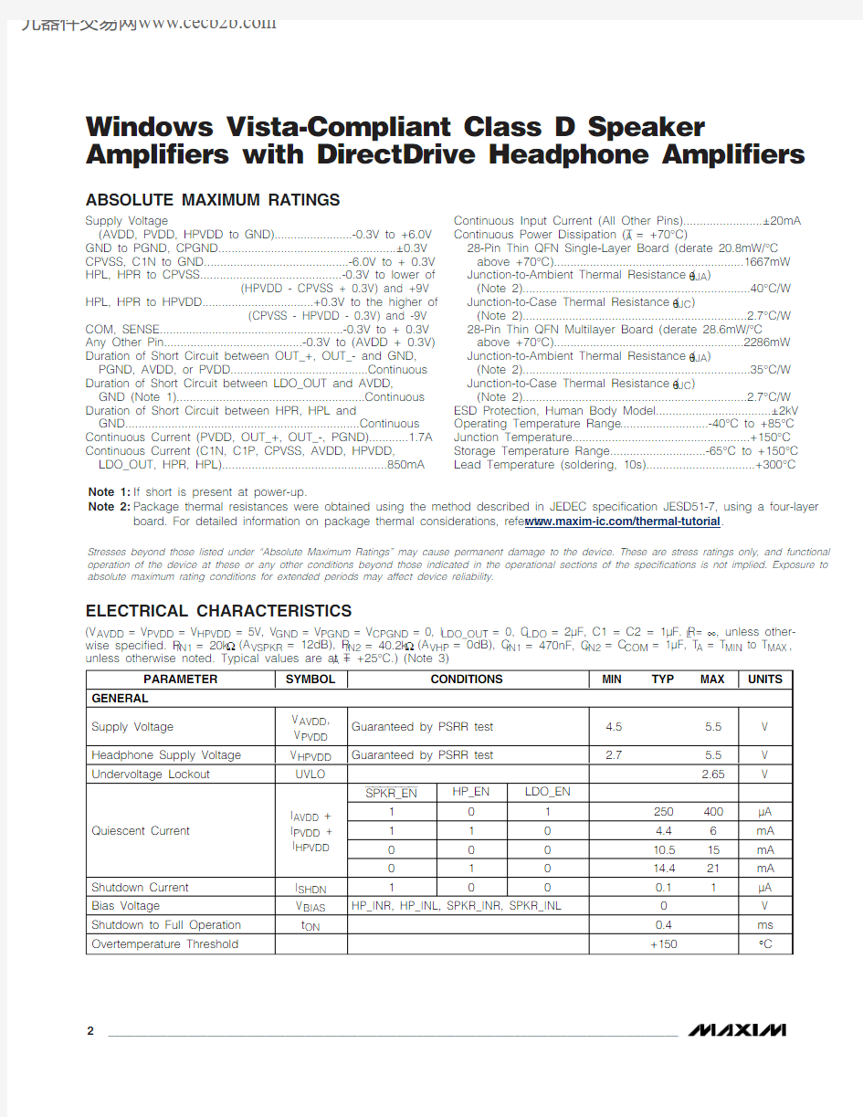
The MAX9791 combines a stereo 2W Class D power amplifier, a stereo 180mW DirectDrive ?headphone amplifier, and a 120mA low-dropout (LDO) linear regu-lator in a single device. The MAX9792 combines a mono 3W Class D power amplifier, a stereo 180mW DirectDrive headphone amplifier, and a 120mA LDO linear regulator in a single device.
The MAX9791/MAX9792 feature Maxim’s patented**DirectDrive headphone amplifier architecture that pro-duces a ground-referenced output from a single supply,eliminating the need for large DC-blocking capacitors,saving cost, board space, and component height. High 107dB DC PSRR and low 0.006% THD+N ensure clean,low-distortion amplification of the audio signal.
The ground sense feature senses and corrects for the voltage difference between the output jack ground and device signal ground. This feature minimizes head-phone amplifier crosstalk by sensing the impedance in the ground return trace and correcting for it at the out-put jack. This feature also minimizes ground-loop noise when the output socket is used as a line out connection to other grounded equipment (for example, a PC con-nected to a home hi-fi system).
The MAX9791/MAX9792 feature low RF susceptibility,allowing the amplifiers to successfully operate in close proximity to wireless applications. The MAX9791/MAX9792 Class D amplifiers feature Maxim’s patented ?spread-spectrum modulation and patented ??active emissions limiting circuitry. Industry-leading click-and-pop suppression eliminates audible transients during power-up and shutdown cycles.
The MAX9791/MAX9792 wake-on-beep feature wakes up the speaker and headphone amplifiers when a qual-ified beep signal is detected at the BEEP input.
For maximum flexibility, separate speaker and head-phone amplifier control inputs provide independent shutdown of the speaker and headphone amplifiers.Additionally the LDO can be enabled independently of the audio amplifiers.
The MAX9791/MAX9792 feature thermal-overload and output short-circuit protection. The devices are avail-able in 28-pin TQFN packages and are specified over the -40°C to +85°C extended temperature range.
Applications
Notebook Computers Tablet PCs
Portable Multimedia Players
Features
?Windows Vista?Premium Compliant
?Low EMI Filterless Class D Speaker Amplifiers Pass EN55022B Emissions Limit with 30cm of Speaker Cable
?180mW DirectDrive Headphone Amplifier ?Excellent RF Immunity ?Integrated 120mA LDO
?Eliminates Headphone Ground Loop Noise ?Wake-on-Beep Function ?Click-and-Pop Suppression
?Short-Circuit and Thermal-Overload Protection ?Thermally Efficient, Space-Saving Package
28-Pin TQFN-EP (4mm x 4mm x 0.75mm)
MAX9791/MAX9792
Windows Vista-Compliant Class D Speaker
Amplifiers with DirectDrive Headphone Amplifiers
________________________________________________________________Maxim Integrated Products
1
19-4217; Rev 0; 11/08
For pricing, delivery, and ordering information,please contact Maxim Direct at 1-888-629-4642,or visit Maxim’s website at https://www.doczj.com/doc/1e13353434.html,.
Ordering Information
Note:All devices are specified over the -40°C to +85°C extended temperature range.
+Denotes a lead-free/RoHS-compliant package.*EP = Exposed pad.
Windows Vista is a registered trademark of Microsoft Corp.Simplified Block Diagrams
DirectDrive is a registered trademark of Maxim Integrated Products, Inc.
**U.S. Patent #7,061,327.?U.S. Patent #6,847,257.??U.S. Patent #7,190,225.
M A X 9791/M A X 9792
Windows Vista-Compliant Class D Speaker
Amplifiers with DirectDrive Headphone Amplifiers 2_______________________________________________________________________________________
ABSOLUTE MAXIMUM RATINGS
ELECTRICAL CHARACTERISTICS
(V AVDD = V PVDD = V HPVDD = 5V, V GND = V PGND = V CPGND = 0, I LDO_OUT = 0, C LDO = 2μF, C1 = C2 = 1μF. R L = ∞, unless other-wise specified. R IN1= 20k Ω(A VSPKR = 12dB), R IN2= 40.2k Ω(A VHP = 0dB), C IN1= 470nF, C IN2= C COM = 1μF, T A = T MIN to T MAX ,unless otherwise noted. Typical values are at T
= +25°C.) (Note 3)
Stresses beyond those listed under “Absolute Maximum Ratings” may cause permanent damage to the device. These are stress ratings only, and functional operation of the device at these or any other conditions beyond those indicated in the operational sections of the specifications is not implied. Exposure to absolute maximum rating conditions for extended periods may affect device reliability.
Supply Voltage
(AVDD, PVDD, HPVDD to GND)........................-0.3V to +6.0V GND to PGND, CPGND......................................................±0.3V CPVSS, C1N to GND............................................-6.0V to + 0.3V HPL, HPR to CPVSS...........................................-0.3V to lower of
(HPVDD - CPVSS + 0.3V) and +9V
HPL, HPR to HPVDD..................................+0.3V to the higher of
(CPVSS - HPVDD - 0.3V) and -9V
COM, SENSE........................................................-0.3V to + 0.3V Any Other Pin..........................................-0.3V to (AVDD + 0.3V)Duration of Short Circuit between OUT_+, OUT_- and GND,PGND, AVDD, or PVDD..........................................Continuous Duration of Short Circuit between LDO_OUT and AVDD,
GND (Note 1).........................................................Continuous Duration of Short Circuit between HPR, HPL and
GND.......................................................................Continuous Continuous Current (PVDD, OUT_+, OUT_-, PGND)............1.7A Continuous Current (C1N, C1P, CPVSS, AVDD, HPVDD,
LDO_OUT, HPR, HPL)..................................................850mA
Continuous Input Current (All Other Pins)........................±20mA Continuous Power Dissipation (T A = +70°C)
28-Pin Thin QFN Single-Layer Board (derate 20.8mW/°C
above +70°C)..........................................................1667mW Junction-to-Ambient Thermal Resistance (θJA )
(Note 2).....................................................................40°C/W Junction-to-Case Thermal Resistance (θJC )
(Note 2)....................................................................2.7°C/W 28-Pin Thin QFN Multilayer Board (derate 28.6mW/°C
above +70°C)..........................................................2286mW Junction-to-Ambient Thermal Resistance (θJA )
(Note 2).....................................................................35°C/W Junction-to-Case Thermal Resistance (θJC )
(Note 2)....................................................................2.7°C/W ESD Protection, Human Body Model...................................±2kV Operating Temperature Range ...........................-40°C to +85°C Junction Temperature......................................................+150°C Storage Temperature Range.............................-65°C to +150°C Lead Temperature (soldering, 10s).................................+300°C
Note 1:If short is present at power-up.
Note 2:Package thermal resistances were obtained using the method described in JEDEC specification JESD51-7, using a four-layer
board. For detailed information on package thermal considerations, refer to https://www.doczj.com/doc/1e13353434.html,/thermal-tutorial .
MAX9791/MAX9792
Windows Vista-Compliant Class D Speaker
Amplifiers with DirectDrive Headphone Amplifiers
ELECTRICAL CHARACTERISTICS (continued)
(V AVDD = V PVDD = V HPVDD = 5V, V GND = V PGND = V CPGND = 0, I LDO_OUT = 0, C LDO = 2μF, C1 = C2 = 1μF. R L = ∞, unless other-wise specified. R = 20k Ω(A = 12dB), R = 40.2k Ω(A = 0dB), C = 470nF, C = C = 1μF, T = T to T ,
M A X 9791/M A X 9792
Windows Vista-Compliant Class D Speaker
Amplifiers with DirectDrive Headphone Amplifiers 4_______________________________________________________________________________________
ELECTRICAL CHARACTERISTICS (continued)
(V AVDD = V PVDD = V HPVDD = 5V, V GND = V PGND = V CPGND = 0, I LDO_OUT = 0, C LDO = 2μF, C1 = C2 = 1μF. R L = ∞, unless other-wise specified. R IN1= 20k Ω(A VSPKR = 12dB), R IN2= 40.2k Ω(A VHP = 0dB), C IN1= 470nF, C IN2= C COM = 1μF, T A = T MIN to T MAX ,unless otherwise noted. Typical values are at T A = +25°C.) (Note 3)
MAX9791/MAX9792
Windows Vista-Compliant Class D Speaker
Amplifiers with DirectDrive Headphone Amplifiers
_______________________________________________________________________________________5
ELECTRICAL CHARACTERISTICS (continued)
(V AVDD = V PVDD = V HPVDD = 5V, V GND = V PGND = V CPGND = 0, I LDO_OUT = 0, C LDO = 2μF, C1 = C2 = 1μF. R L = ∞, unless other-
M A X 9791/M A X 9792
Windows Vista-Compliant Class D Speaker
Amplifiers with DirectDrive Headphone Amplifiers 6_______________________________________________________________________________________
Note 3:All devices are 100% production tested at room temperature. All temperature limits are guaranteed by design.
Note 4:Testing performed with a resistive load in series with an inductor to simulate an actual speaker load. For R L = 3Ω, L = 22μH.
For R L = 4Ω, L = 33μH. For R L = 8Ω, L = 68μH.
Note 5:Specified at T A = +25°C with an 8Ω+ 68μH load connected across BTL output for speaker amplifier. Specified at T A = +25°C
with a 32Ωresistive load connected between HPR, HPL and GND for headphone amplifier. Speaker and headphone mode transitions are controlled by SPKR_EN and HP_EN inputs, respectively.
Note 6:Amplifier Inputs AC-coupled to GND.
Note 7:Guaranteed by ATE characterization; limits are not production tested.
TOTAL HARMONIC DISTORTION + NOISE vs. FREQUENCY (MAX9792 SPEAKER MODE)
FREQUENCY (kHz)
T H D +N (d B F S )
0.1
1
10
-90-80-50-40-30-70-60-20-100-100
0.01
100
TOTAL HARMONIC DISTORTION + NOISE
vs. FREQUENCY (MAX9791 SPEAKER MODE)
FREQUENCY (kHz)
T H D +N (d B F S )
0.1
1
10
-90-80
-50-40-30-70-60-20-100-100
0.01
100
TOTAL HARMONIC DISTORTION + NOISE vs. FREQUENCY (MAX9791 SPEAKER MODE)
FREQUENCY (kHz)
T H D +N (d B F S )
0.1
1
10-90-80-50-40-30-70
-60-20-100
-100
0.01
100
TOTAL HARMONIC DISTORTION + NOISE vs. OUTPUT POWER (MAX9792 SPEAKER MODE)
OUTPUT POWER (W)
T H D +N (%)
1.0
2.0
3.0
0.01
0.11
10
100
0.001
4.0
0.5
1.5
2.5
3.5
TOTAL HARMONIC DISTORTION + NOISE vs. OUTPUT POWER (MAX9791 SPEAKER MODE)
OUTPUT POWER (W)
T H D +N (%)
2.0
1.5
1.0
0.01
0.11
10
100
0.001
3.0
2.5
0.5
TOTAL HARMONIC DISTORTION + NOISE vs. OUTPUT POWER (MAX9791 SPEAKER MODE)
OUTPUT POWER (W)
T H D +N (%)
0.5 1.0
0.01
0.11
10
100
0.001
0 2.0
1.5Typical Operating Characteristics
(V AVDD = V PVDD = V HPVDD = 5V, V GND = V PGND = V CPGND = 0, I LDO_OUT = 0, C LDO = 2 x 1μF, C1 = C2 = 1μF. R L = ∞, unless oth-erwise specified. R IN1= 20k Ω(A VSPKR = 12dB), R IN2= 40.2k Ω(A VHP = 0dB), C IN1= 470nF, C IN2= C COM = 1μF, measurement BW = 20kHz AES17, T A = +25°C, unless otherwise noted. Speaker mode: SPKR_EN = 0, HP_EN = 0. Headphone mode: SPKR_EN = 1,HP_EN = 1.)
SPEAKER
ELECTRICAL CHARACTERISTICS (continued)
(V AVDD = V PVDD = V HPVDD = 5V, V GND = V PGND = V CPGND = 0, I LDO_OUT = 0, C LDO = 2μF, C1 = C2 = 1μF. R L = ∞, unless other-wise specified. R IN1= 20k Ω(A VSPKR = 12dB), R IN2= 40.2k Ω(A VHP = 0dB), C IN1= 470nF, C IN2= C COM = 1μF, T A = T MIN to T MAX ,unless otherwise noted. Typical values are at T A = +25°C.) (Note 3)
MAX9791/MAX9792
Windows Vista-Compliant Class D Speaker
Amplifiers with DirectDrive Headphone Amplifiers
_______________________________________________________________________________________7
OUTPUT POWER vs. LOAD RESISTANCE
(MAX9792 SPEAKER MODE)
LOAD RESISTANCE (Ω)O U T P U T P O W E R (W )
10
1.02.03.04.05.001.52.53.54.50.51
100
OUTPUT POWER vs. LOAD RESISTANCE
(MAX9791 SPEAKER MODE)
LOAD RESISTANCE (Ω)
O U T P U T P O W E R (W )
10
1.02.0
3.00
1.5
2.50.51100
EFFICIENCY vs. OUTPUT POWER (MAX9792 SPEAKER MODE)
OUTPUT POWER (W)
E F F I C I E N C Y (%)
1.0
2.0
3.0
708090100110
2010304050600
4.0
0.5
1.5
2.5
3.5
EFFICIENCY vs. OUTPUT POWER (MAX9791 SPEAKER MODE)
OUTPUT POWER (W)
E F F I C I E N C Y (%)
1.50.9
0.6
70809010020103040506000
1.81.2
0.3
POWER-SUPPLY REJECTION RATIO vs. FREQUENCY (SPEAKER MODE)
FREQUENCY (kHz)
P S R R (d B )
1
-30-20-10-80-90-70-60-50-40-100
0.01100
0.1100CROSSTALK vs. FREQUENCY
(SPEAKER MODE)
FREQUENCY (kHz)
C R O S S T A L K (d B )
1
-30-20-10-80-90-100-70-60-50-40-110
0.01
100
0.1
10
Typical Operating Characteristics (continued)
(V AVDD = V PVDD = V HPVDD = 5V, V GND = V PGND = V CPGND = 0, I LDO_OUT = 0, C LDO = 2 x 1μF, C1 = C2 = 1μF. R L = ∞, unless oth-erwise specified. R IN1= 20k Ω(A VSPKR = 12dB), R IN2= 40.2k Ω(A VHP = 0dB), C IN1= 470nF, C IN2= C COM = 1μF, measurement BW = 20kHz AES17, T A = +25°C, unless otherwise noted. Speaker mode: SPKR_EN = 0, HP_EN = 0. Headphone mode: SPKR_EN = 1,HP_EN = 1.)
SPEAKER
M A X 9791/M A X 9792
Windows Vista-Compliant Class D Speaker
Amplifiers with DirectDrive Headphone Amplifiers 8
_______________________________________________________________________________________
SPEAKER STARTUP WAVEFORM
MAX9791 toc13
SPKR_EN 2V/div SPEAKER OUT
200μs/div SPEAKER SHUTDOWN WAVEFORM
MAX9791 toc14
SPKR_EN 2V/div
SPEAKER OUT
200μs/div
WIDEBAND OUTPUT SPECTRUM
(SPEAKER MODE)
FREQUENCY (MHz)
O U T P U T A M P L I T U D E (d B V )
10
1
-110-100-90-80-70-60-50-40-30-20-100
-120
100
OUTPUT FREQUENCY SPECTRUM
(SPEAKER MODE)
FREQUENCY (kHz)
O U T P U T M A G N I T U D E (d B V )
10-100-600-140
-80-40-20-120120
515Typical Operating Characteristics (continued)
(V AVDD = V PVDD = V HPVDD = 5V, V GND = V PGND = V CPGND = 0, I LDO_OUT = 0, C LDO = 2 x 1μF, C1 = C2 = 1μF. R L = ∞, unless oth-erwise specified. R IN1= 20k Ω(A VSPKR = 12dB), R IN2= 40.2k Ω(A VHP = 0dB), C IN1= 470nF, C IN2= C COM = 1μF, measurement BW = 20kHz AES17, T A = +25°C, unless otherwise noted. Speaker mode: SPKR_EN = 0, HP_EN = 0. Headphone mode: SPKR_EN = 1,HP_EN = 1.)
SPEAKER
MAX9791/MAX9792
Windows Vista-Compliant Class D Speaker
Amplifiers with DirectDrive Headphone Amplifiers
_______________________________________________________________________________________9
TOTAL HARMONIC DISTORTION + NOISE vs. FREQUENCY (HEADPHONE MODE)
FREQUENCY (kHz)
T H D +N (d B F S )
1
-80
-90
-70
-60-100
0.01
100
0.1
10
-50
TOTAL HARMONIC DISTORTION + NOISE vs. FREQUENCY (HEADPHONE MODE)
FREQUENCY (kHz)
T H D +N (d B F S )
1
-80
-90
-70-60-100
0.01
100
0.1
10
-50
TOTAL HARMONIC DISTORTION + NOISE vs. FREQUENCY (HEADPHONE MODE)
FREQUENCY (kHz)
T H D +N (d B F S )
1
-80-90
-70
-60-100
0.01
100
0.1
10
-50
TOTAL HARMONIC DISTORTION + NOISE
vs. FREQUENCY (HEADPHONE MODE)
FREQUENCY (kHz)
T H D +N (d B F S )
1
-80-90
-70
-60-100
0.01
100
0.1
10
-50
TOTAL HARMONIC DISTORTION + NOISE vs. OUTPUT POWER (HEADPHONE MODE)
OUTPUT POWER (mW)T H D +N (%)
160
0.10.01
1
100.001
200
120
40
80
100
TOTAL HARMONIC DISTORTION + NOISE vs. OUTPUT POWER (HEADPHONE MODE)
OUTPUT POWER (mW)
T H D +N (%)
0.1
0.01
1
100.001
50
250
200
150
100
100
TOTAL HARMONIC DISTORTION + NOISE vs. OUTPUT POWER (HEADPHONE MODE)
OUTPUT POWER (mW)
T H D +N (%)
10
0.10.01
1
100.001
50
40
90
80
70
60
30
20
100
TOTAL HARMONIC DISTORTION + NOISE
vs. OUTPUT POWER (HEADPHONE MODE)
OUTPUT POWER (mW)
T H D +N (%)
10
0.1
0.01
1
100.001
50
40
70
60
30
20
100
OUTPUT POWER vs. LOAD RESISTANCE
(HEADPHONE MODE)
LOAD RESISTANCE (Ω)
O U T P U T P O W E R (m W )
10
50
150
250
01002001
100
Typical Operating Characteristics (continued)
(V AVDD = V PVDD = V HPVDD = 5V, V GND = V PGND = V CPGND = 0, I LDO_OUT = 0, C LDO = 2 x 1μF, C1 = C2 = 1μF. R L = ∞, unless oth-erwise specified. R IN1= 20k Ω(A VSPKR = 12dB), R IN2= 40.2k Ω(A VHP = 0dB), C IN1= 470nF, C IN2= C COM = 1μF, measurement BW = 20kHz AES17, T A = +25°C, unless otherwise noted. Speaker mode: SPKR_EN = 0, HP_EN = 0. Headphone mode: SPKR_EN = 1,HP_EN = 1.)
HEADPHONE
M A X 9791/M A X 9792
Windows Vista-Compliant Class D Speaker
Amplifiers with DirectDrive Headphone Amplifiers 10______________________________________________________________________________________
OUTPUT POWER vs. LOAD RESISTANCE
(HEADPHONE MODE)
LOAD RESISTANCE (Ω)O U T P U T P O W E R (m W )
100
507090060801030204010
1000POWER DISSIPATION vs. OUTPUT POWER
(HEADPHONE MODE)
PER CHANNEL OUTPUT POWER (mW)P O W E R D I S S I P A T I O N P E R C H A N N E L (m W )
50
1001502002503005010015035040000
20025
75
125175
POWER DISSIPATION vs. OUTPUT POWER
(HEADPHONE MODE)
PER CHANNEL OUTPUT POWER (mW)
P O W E R D I S S I P A T I O N P E R C H A N N E L (m W )
2010015020050250300
0100
804060
HEADPHONE OUTPUT POWER
vs. HPVDD VOLTAGE
V HPVDD (V)
H E A D P H O N E O U T P U T P O W E R (m W )
3.5
100
150200
50
25003.0
5.5
5.0
4.0
4.5
POWER-SUPPLY REJECTION RATIO vs. FREQUENCY (HEADPHONE MODE)
FREQUENCY (kHz)
P S R R (d B )
0.1
1
10
-90-80-110
-100-50-40-30-70-60-20-100-120
0.01
100
CROSSTALK vs. FREQUENCY
(HEADPHONE MODE)
FREQUENCY (kHz)
C R O S S T A L K (d B )
0.1
1
10
-90-80
-50-40-30-70-60-20
-100
0.01
100
OUTPUT FREQUENCY SPECTRUM
(HEADPHONE MODE)
FREQUENCY (kHz)
O U T P U T F R E Q U E N C Y S P E C T R U M (d B )
5
1015
-120-100-40-200-80-60-140
20
MAX9791 toc33
HP_EN 2V/div
HP_
500mV/div
200μs/div
STARTUP WAVEFORM
Typical Operating Characteristics (continued)
(V AVDD = V PVDD = V HPVDD = 5V, V GND = V PGND = V CPGND = 0, I LDO_OUT = 0, C LDO = 2 x 1μF, C1 = C2 = 1μF. R L = ∞, unless oth-erwise specified. R IN1= 20k Ω(A VSPKR = 12dB), R IN2= 40.2k Ω(A VHP = 0dB), C IN1= 470nF, C IN2= C COM = 1μF, measurement BW = 20kHz AES17, T A = +25°C, unless otherwise noted. Speaker mode: SPKR_EN = 0, HP_EN = 0. Headphone mode: SPKR_EN = 1,HP_EN = 1.)
HEADPHONE
MAX9791/MAX9792
Windows Vista-Compliant Class D Speaker
Amplifiers with DirectDrive Headphone Amplifiers
______________________________________________________________________________________11
-130
-90-110-50
-70-30
-10500
1500
1000
2000
2500
3000
HEADPHONE RF IMMUNITY
vs. FREQUENCY
FREQUENCY (MHz)A M P L I T U D E (d B V )
MAX9791 toc34
HP_EN 2V/div
HP_
500mV/div
200μs/div
SHUTDOWN WAVEFORM
HEADPHONE
Typical Operating Characteristics (continued)
(V AVDD = V PVDD = V HPVDD = 5V, V GND = V PGND = V CPGND = 0, I LDO_OUT = 0, C LDO = 2 x 1μF, C1 = C2 = 1μF. R L = ∞, unless oth-erwise specified. R IN1= 20k Ω(A VSPKR = 12dB), R IN2= 40.2k Ω(A VHP = 0dB), C IN1= 470nF, C IN2= C COM = 1μF, measurement BW = 20kHz AES17, T A = +25°C, unless otherwise noted. Speaker mode: SPKR_EN = 0, HP_EN = 0. Headphone mode: SPKR_EN = 1,HP_EN = 1.)
M A X 9791/M A X 9792
Windows Vista-Compliant Class D Speaker
Amplifiers with DirectDrive Headphone Amplifiers 12______________________________________________________________________________________
TOTAL HARMONIC DISTORTION + NOISE vs. FREQUENCY (HEADPHONE MODE)
FREQUENCY (kHz)
T H D +N (d B F S )
0.1
1
10
-90-100-80-50-40
-30-70-60-20-100-110
0.01
100TOTAL HARMONIC DISTORTION + NOISE vs. FREQUENCY (HEADPHONE MODE)
FREQUENCY (kHz)
T H D +N (d B F S )
0.11
10-90-100-80-50-40-30-70-60-20-100-110
0.01100
TOTAL HARMONIC DISTORTION + NOISE vs. OUTPUT POWER (HEADPHONE MODE)
OUTPUT POWER (mW)
T H D +N (%)
1.0
2.0
3.00.001
0.010.1110100
0.0001
0 4.0
0.5 1.5 2.5 3.5Typical Operating Characteristics (continued)
(V AVDD = V PVDD = V HPVDD = 5V, V GND = V PGND = V CPGND = 0, I LDO_OUT = 0, C LDO = 2 x 1μF, C1 = C2 = 1μF. R L = ∞, unless oth-erwise specified. R IN1= 20k Ω(A VSPKR = 12dB), R IN2= 40.2k Ω(A VHP = 0dB), C IN1= 470nF, C IN2= C COM = 1μF, measurement BW = 20kHz AES17, T A = +25°C, unless otherwise noted. Speaker mode: SPKR_EN = 0, HP_EN = 0. Headphone mode: SPKR_EN = 1,HP_EN = 1.)
LINE OUT
TOTAL HARMONIC DISTORTION + NOISE vs. OUTPUT POWER (HEADPHONE MODE)
OUTPUT POWER (mW)
T H D +N (%)
2.0
1.5
1.0
0.001
0.010.11101000.0001
3.0
2.5
0.5
CROSSTALK vs. FREQUENCY
(HEADPHONE MODE)
FREQUENCY (kHz)
C R O S S T A L K (d B )
0.1
1
10
-90-80-110-100
-50-40-30-70-60-20
-120
0.01
100
OUTPUT FREQUENCY SPECTRUM
(HEADPHONE MODE)
FREQUENCY (kHz)
O U T P U T F R E Q U E N C Y S P E C T R U M (d B )
5
1015
-120-100-40-200-80-60-140
20
MAX9791/MAX9792
Windows Vista-Compliant Class D Speaker
Amplifiers with DirectDrive Headphone Amplifiers
______________________________________________________________________________________13
SUPPLY CURRENT vs. SUPPLY VOLTAGE
SUPPLY VOLTAGE (V)
S U P P L Y C U R R E N T (m A )
4.75
5.00
510
1520-54.50
5.50
5.25
SHUTDOWN CURRENT vs. SUPPLY VOLTAGE
SUPPLY VOLTAGE (V)
S H U T D O W N C U R R E N T (μA )
4.75
5.00
0.04
0.08
0.120.16
0.20
04.50
5.50
5.25
Typical Operating Characteristics (continued)
(V AVDD = V PVDD = V HPVDD = 5V, V GND = V PGND = V CPGND = 0, I LDO_OUT = 0, C LDO = 2 x 1μF, C1 = C2 = 1μF. R L = ∞, unless oth-erwise specified. R IN1= 20k Ω(A VSPKR = 12dB), R IN2= 40.2k Ω(A VHP = 0dB), C IN1= 470nF, C IN2= C COM = 1μF, measurement BW = 20kHz AES17, T A = +25°C, unless otherwise noted. Speaker mode: SPKR_EN = 0, HP_EN = 0. Headphone mode: SPKR_EN = 1,HP_EN = 1.)
GENERAL
M A X 9791/M A X 9792
Windows Vista-Compliant Class D Speaker
Amplifiers with DirectDrive Headphone Amplifiers 14______________________________________________________________________________________
LDO OUTPUT ACCURACY vs. LOAD CURRENT
M A X 9791 t o c 44
LOAD CURRENT (mA)L D O O U T P U T A C C U R A C Y (%)
125
75
-1.0-1.500.51.0-0.51.52.0-2.0
15025
100
50
POWER-SUPPLY REJECTION RATIO
vs. FREQUENCY LDO
FREQUENCY (kHz)
P S R R (d B )
101
0.1-80-60-40-2002040-100
0.01100
010050200
1502503000
100
15050
200
250
300
LDO DROPOUT VOLTAGE vs. LOAD
I LOAD (mA)
L D O D R O P O U T V O L T A G E (m V )
LDO OUTPUT NOISE
FREQUENCY (kHz)
L D O O U T P U T N O I S E (μV )
101
0.17510012515017520050
0.01100
LDO OUTPUT ACCURACY vs. TEMPERATURE
TEMPERATURE (°C)
L D O O U T P U T A C C U R A C Y (%)
603510-15-0.5
0.5
1.0
-1.0
-40
85
LDO OUTPUT ACCURACY vs. AMPLIFIER OUTPUT POWER
M A X 9791 t o c 45
AMPLIFIER OUTPUT POWER (mW)L D O O U T P U T A C C U R A C Y (%)
300
0.040.030.020.010.060.070.080.050.090.100
1500
1200
600
900
Typical Operating Characteristics (continued)
(V AVDD = V PVDD = V HPVDD = 5V, V GND = V PGND = V CPGND = 0, I LDO_OUT = 0, C LDO = 2 x 1μF, C1 = C2 = 1μF. R L = ∞, unless oth-erwise specified. R IN1= 20k Ω(A VSPKR = 12dB), R IN2= 40.2k Ω(A VHP = 0dB), C IN1= 470nF, C IN2= C COM = 1μF, measurement BW = 20kHz AES17, T A = +25°C, unless otherwise noted. Speaker mode: SPKR_EN = 0, HP_EN = 0. Headphone mode: SPKR_EN = 1,HP_EN = 1.)
LDO
MAX9791/MAX9792
Windows Vista-Compliant Class D Speaker
Amplifiers with DirectDrive Headphone Amplifiers
______________________________________________________________________________________
15
CROSSTALK vs. FREQUENCY
SPEAKER TO LDO
FREQUENCY (kHz)
C R O S S T A L K (d B )
101
0.1-120-110-100-90-80-70-60-50-40-30-20-100-130
0.01100
Typical Operating Characteristics (continued)
(V AVDD = V PVDD = V HPVDD = 5V, V GND = V PGND = V CPGND = 0, I LDO_OUT = 0, C LDO = 2 x 1μF, C1 = C2 = 1μF. R L = ∞, unless oth-erwise specified. R IN1= 20k Ω(A VSPKR = 12dB), R IN2= 40.2k Ω(A VHP = 0dB), C IN1= 470nF, C IN2= C COM = 1μF, measurement BW = 20kHz AES17, T A = +25°C, unless otherwise noted. Speaker mode: SPKR_EN = 0, HP_EN = 0. Headphone mode: SPKR_EN = 1,HP_EN = 1.)
LDO
200μs/div
SHUTDOWN RESPONSE
LDO_EN 2V/div
MAX9791 toc52
V LDO_EN 2V/div
100ms/div
LOAD-TRANSIENT RESPONSE
I LDO_OUT 50mV/div
MAX9791 toc51
AC-COUPLED V LDO_OUT 10mV/div
1.00ms/div
LINE-TRANSIENT RESPONSE
CH1 LOW 4.560V
CH1 HIGH 5.500V CH2 HIGH 1.000mV
CH2 LOW 800.0μV MAX9791 toc50
M A X 9791/M A X 9792
Windows Vista-Compliant Class D Speaker
Amplifiers with DirectDrive Headphone Amplifiers 16______________________________________________________________________________________
MAX9791 Pin Description
MAX9791/MAX9792
Windows Vista-Compliant Class D Speaker
Amplifiers with DirectDrive Headphone Amplifiers
______________________________________________________________________________________17
Detailed Description
The MAX9791 combines a stereo 2W Class D power
amplifier, a stereo 175mW DirectDrive headphone amplifier, and a 120mA LDO linear regulator in a single device. The MAX9792 combines a mono 3W Class D power amplifier, a stereo 175mW DirectDrive head-phone amplifier, and a 120mA LDO linear regulator in a single device.
The MAX9791/MAX9792 feature wake-on-beep detec-tion, comprehensive click-and-pop suppression, low-power shutdown mode, and excellent RF immunity.These devices incorporate an integrated LDO that serves as a clean power supply for CODEC or other cir-cuits. The MAX9791/MAX9792 are Windows Vista Premium compliant. See Table 1 for a comparison of the Windows Vista Premium specifications and MAX9791/MAX9792 specifications.
The MAX9791/MAX9792 feature spread-spectrum mod-ulation and active emission limiting circuitry that offers significant improvements to switch-mode amplifier tech-nology. These devices offer Class AB performance with Class D efficiency in a minimal board-space solution.The headphone amplifiers use Maxim’s patented DirectDrive architecture to eliminate the bulky output DC-blocking capacitors required by traditional head-phone amplifiers. A charge pump inverts the positive supply (HPVDD) to create a negative supply (CPVSS).The headphone amplifiers operate from these bipolar supplies with their outputs biased about GND. The ben-efit of the GND bias is that the amplifier outputs no longer have a DC component (typically V DD /2). This feature eliminates the large DC-blocking capacitors required with conventional headphone amplifiers to
MAX9792 Pin Description
M A X 9791/M A X 9792
Windows Vista-Compliant Class D Speaker
Amplifiers with DirectDrive Headphone Amplifiers 18______________________________________________________________________________________
conserve board space and system cost, as well as improve low-frequency response and distortion.
The MAX9791/MAX9792 amplifiers feature an under-voltage lockout that prevents operation from an insuffi-cient power supply and click-and-pop suppression that eliminates audible transients on startup and shutdown.The amplifiers include thermal overload and short-cir-cuit protection.
Class D Speaker Amplifier
The MAX9791/MAX9792 integrate a filterless class D amplifier that offers much higher efficiency than class AB amplifiers. The high efficiency of a Class D amplifier is due to the switching operation of the output stage tran-sistors. In a Class D amplifier, the output transistors act as current steering switches and consume negligible additional power. Any power loss associated with the Class D output stage is mostly due to the I2R loss of the MOSFET on-resistance and quiescent current overhead.The theoretical best efficiency of a linear amplifier is 78%, however, that efficiency is only exhibited at peak output power. Under normal operating levels (typical music reproduction levels), efficiency falls below 45%,whereas the MAX9791/MAX9792 exhibit 67% efficiency under the same conditions (Figure 1).
Ultra-Low EMI Filterless Output Stage
In traditional Class D amplifiers, the high dv/dt of the rising and falling edge transitions resulted in increased electromagnetic-interference (E MI) emissions, which required the use of external LC filters or shielding to meet EN55022B EMI regulation standards. Limiting the dv/dt normally results in decreased efficiency. Maxim’s active emissions limiting circuitry actively limits the dv/dt of the rising and falling edge transitions, providing reduced E MI emissions while maintaining up to 83%efficiency.
Figure 1. MAX9791 Efficiency vs. Class AB Efficiency
ments standards.
MAX9791/MAX9792
Windows Vista-Compliant Class D Speaker
Amplifiers with DirectDrive Headphone Amplifiers
______________________________________________________________________________________19
In addition to active emission limiting, the MAX9791/MAX9792 feature patented spread-spectrum modulation that flattens the wideband spectral components.Proprietary techniques ensure that the cycle-to-cycle variation of the switching period does not degrade audio reproduction or efficiency (see the Typical Operating Characteristics ). In spread-spectrum modulation mode,the switching frequency varies randomly by ±15kHz around the center frequency (530kHz). The effect is to reduce the peak energy at harmonics of the switching frequency. Above 10MHz, the wideband spectrum looks like noise for EMI purposes (see Figure 2).
Speaker Current Limit
When the output current of the speaker amplifier exceeds the current limit (2A, typ) the MAX9791/MAX9792 disable the outputs for approximately 100μs.At the end of 100μs, the outputs are re-enabled. If the fault condition still exists, the MAX9791/MAX9792 con-tinue to disable and re-enable the outputs until the fault condition is removed.
DirectDrive Headphone Amplifier
Traditional single-supply headphone amplifiers bias the outputs at a nominal DC voltage (typically half the sup-ply). Large coupling capacitors are needed to block this DC bias from the headphone. Without these capac-itors, a significant amount of DC current flows to the headphone, resulting in unnecessary power dissipation and possible damage to both headphone and head-phone amplifier.
Maxim’s patented DirectDrive architecture uses a charge pump to create an internal negative supply volt-age. This allows the headphone outputs of the MAX9791/MAX9792 to be biased at GND while operat-ing from a single supply (Figure 3). Without a DC com-ponent, there is no need for the large DC-blocking capacitors. Instead of two large (220μF, typ) capaci-tors, the MAX9791/MAX9792 charge pump requires two small 1μF ceramic capacitors, conserving board space,reducing cost, and improving the frequency response of the headphone amplifier.
The MAX9791/MAX9792 feature a low-noise charge pump. The nominal switching frequency of 530kHz is well beyond the audio range, and thus does not inter-fere with audio signals. The switch drivers feature a controlled switching speed that minimizes noise gener-ated by turn-on and turn-off transients. By limiting the switching speed of the charge pump, the di/dt noise caused by the parasitic trace inductance is minimized.
FREQUENCY (MHz)
100
30
1000
Figure 2. EMI with 30cm of Speaker Cable
Figure 3. Traditional Amplifier Output vs. MAX9791/MAX9792DirectDrive Output
M A X 9791/M A X 9792
Windows Vista-Compliant Class D Speaker
Amplifiers with DirectDrive Headphone Amplifiers 20______________________________________________________________________________________
Common-Mode Sense
Windows Vista-compliant platforms are restricted to only 115m Ωof ground return impedance. If the headphone jack ground is connected close to the audio device ground using a solid ground plane, the return path resis-tance can be quite low. However, it is often necessary to locate some jacks far from the audio device. The MAX9791/MAX9792 COM and SE NSE inputs allow the headphone jack to be placed further away from the device without degrading crosstalk performance.
The MAX9791/MAX9792 SENSE and COM inputs sense and correct for the difference between the headphone return and device ground. When using common-mode sense, connect COM through a resistor to GND of the device (Figure 4). For optimum common-mode rejec-tion, use the same value resistors for R IN2and R COM .To improve AC CMRR, add a capacitor equal to C IN2between GND and R COM .
Configuring SENSE and COM in this way improves sys-tem crosstalk performance by reducing the negative effects of the headphone jack ground return resistance.
The headphone amplifier output impedance, trace resistance, and contact resistance of the jack are grouped together to represent the source resistance,R S . The resistance between the load and the sleeve,the sleeve contact resistance, and the system ground return resistance are grouped together to represent the ground resistance, R G .
Assuming a typical source resistance of 5Ω, the ground return impedance would need to be limited to 115m Ωto meet Windows Vista’s crosstalk specification of 50dB (Figure 5). This is further complicated by the fact that the impedance of the sleeve connection in the 3.5mm stereo jack can make up 30m Ω–90m Ωalone.
The MAX9791/MAX9792 COM and SE NSE inputs reduce crosstalk performance by eliminating effects of 28.5m Ωof ground return path resistance. If ground sensing is not required, connect COM directly to GND and leave SENSE unconnected (Figure 6).
Wake-on-Beep
The MAX9791/MAX9792 beep-detection circuit wakes up the device (speaker and headphone amplifiers)once a qualified beep signal is detected at BE E P and the LDO is enabled. The amplifier wake command from the beep-detection circuit overrides the logic signal applied at HP_EN and SPKR_EN
.
Figure 4. Connecting COM for Ground Sense
Figure 5. Crosstalk vs. Ground Resistance