Noble Metal Coated Single-Walled Carbon Nanotubes for
- 格式:pdf
- 大小:7.11 MB
- 文档页数:9
金属靶材英语半导体Metal target materials are essential components in the production of semiconductors. These materials are used in physical vapor deposition (PVD) processes, such as sputtering, to deposit thin films of metal onto semiconductor substrates. Metal targets are made from various high-purity metals, including aluminum, copper, titanium, and others, depending on the specificrequirements of the semiconductor manufacturing process.Metal targets play a crucial role in the semiconductor industry by providing a source of metal atoms for thin film deposition. During the sputtering process, high-energy ions bombard the metal target, causing atoms to be ejected from the target surface and deposit onto the semiconductor wafer, creating a thin film. The properties of the metal target, such as purity, uniformity, and grain size, directly impact the quality and performance of the deposited thin films.The selection of metal target materials is based on thedesired properties of the thin film being deposited. For example, aluminum targets are used for the deposition of aluminum thin films, which are commonly used in integrated circuits and other semiconductor devices. Similarly, copper targets are used for the deposition of copper thin films, which are essential for interconnects and wiring in semiconductor devices.In addition to the choice of metal material, the fabrication and quality of the metal targets are also critical. High-purity metals with low levels of impurities are required to ensure the integrity of the thin films and the overall performance of the semiconductor devices. Furthermore, the uniformity of the target material and its microstructure can impact the uniformity and adhesion of the deposited thin films.In summary, metal target materials are integral to the production of semiconductors through PVD processes. The selection of the appropriate metal target material, along with its purity, uniformity, and microstructure, directly influences the quality and performance of the thin filmsdeposited on semiconductor substrates. Therefore, the careful consideration of metal target materials is crucial in the manufacturing of high-quality semiconductor devices.。

化学气相沉积法制备多壁碳纳米管第35卷第11期2007年11月化工新型材料NEWCHEMICALMATERIALSV ol.35No.1137?化学气相沉积法制备多壁碳纳米管张璐朱红林海燕曹旭东(1.北京交通大学理学院化学所,北京100044;2.渥太华大学化学工程学院,加拿大渥太华KIN6N5)摘要以带程序升温装置的管式电阻炉为实验装置,采用化学气相沉积法,在一定的工艺条件下裂解二茂铁与双鸭山精煤的混合物制备出多壁碳纳米管.采用透射电镜,Raman光谱以及X射线衍射技术对碳纳米管产物进行袁征,同时研究了碳纳米管的生长机理.关键词碳纳米管,煤,化学气相沉积Synthesisofmulti—walledcarbonnanotubesbychemicalvapordepositionmethodZhangLuZhuHongLinHaiyanCaoXudong(1.DepartmentofChemistry,SchoolofScience,BeijingJiaotongUniversity,Beiiing10004 4;2.DepartmentofChemicalEngineering,UniversityofOttawa,Ottawa,Ontario,Canada,KI N6N5)AbstractMulti-walledcarbonnanotubes(MWNTs)weresuccessfullypreparedbychemical vapordepositionmethodwiththemixtureofferroceneandShuangyashanfinecoalasreactants.Ahorizontaltu bereactorwithaprogram- mableheatingsysthemwasusedastheexperimentalinstrument.TheMWNTsproductswere characterizedbytransmissionelectronmicroscopy(TEM),RamanspectroscopyandX-raydiffractiontechniques.Thegro wthmechanismofMWNTswasstudied.Keywordscarbonnanotube,coal,chemicalvapordeposition自碳纳米管(CNTs)发现以来_I],就以其独特的性质和潜在的应用前景引起了人们的广泛关注.有关CNTs的制备以及表征已经有大量的报道.CNTs的制备方法包括电弧法_2],激光蒸发法_3],化学气相沉积法(C,厂D)]等.其中,前两种方法需要较高的温度条件,制备的CNTs质量好,然而产量低,不适合工业化生产.相反,人们已证明CVD法可以用来大规模制备CNTs,它所需要的温度也相对较低(550~IO00~C)E.本研究采用CVD法,以带程序升温装置的管式电阻炉为实验装置,在一定的工艺条件下裂解二茂铁与双鸭山精煤的混合物制备多壁碳纳米管(MWNTs),同时研究了CNTs的生长机理.1实验部分1.1煤样固定碳和挥发分是表征煤中主要成分有机质性质的主要工艺性指标,灰分是煤中矿物质含量多少的度量指标_8].一般认为煤中固定碳含量高,意味着在化学气相沉积法中参与纳米碳材料形成的活性碳离子浓度高,从总体上有利于碳纳米管的形成.本方法采用的双鸭山精煤的固定碳含量达8O以上.对煤样进行粉碎,过140目筛.1-2化学气相沉积制备MWNTs反应装置是带有程序升温装置的管式电阻炉.其结构如图1所示.石英管的内径为18ram,长度为ll0cm.管式炉的有效温度区为300ram,位于石英管的中间部位.图1煤制多壁碳纳米管的实验装置图oeouples取适量精煤,与二茂铁以质量比1:3均匀混合,将其装入瓷舟中,再将瓷舟放入石英管的中央部位(反应区),通Nz50mL/min约15min排空.设置好反应时间3h和反应温度1000~C,开始加热.整个实验过程在N2保护下进行.实验结束后,在石英管管壁上及瓷舟中收产物.1.3M的表征用透射电镜(TEM,JEM-2010)观察碳纳米管粗产物的形貌,尺寸和结构.用Raman光谱(RenishawRM2000,632.8基金项目:国家863项目(2006AA03Z226);北京自然科学基金(29051001);国际合作项目(2OO6DFA6124O)作者简介:张璐(1985一),女,在读硕士,主要从事碳纳米管的研究.38化工新型材料第35卷nlTlHe-Nelaser)对产物的结构进行表征.产物的物相组成通过x射线衍射(XRD,XD-D1)观察.2结果与讨论为了研究碳纳米管的生长机理,采用TEM对产物进行表征,如图2所示.从图2a可以看出,有大量碳纳米管生成,同时存在一些杂质如催化剂颗粒和无定形炭等;图2b是单根碳纳米管的透射电镜图.可以看出,管径分布较均匀,碳管的端部封闭,含有金属催化剂颗粒,碳管管体中也存在一些金属颗粒,说明金属颗粒的催化作用可以在两侧同时进行,在制备过程中这些颗粒受到来自两侧的推力,被包覆在管体中_g,并造成碳管在颗粒处拐弯和变形的现象,如图2c所示.从图2c也可以看出,生成的碳管为MWNTs,碳管的内径和外径分布范围分别在4~10nm,24~40nm之间.图2碳纳米管的TEM图图3是碳纳米管的Raman光谱图.Raman光谱在1593.8cm处的G峰表明,制备的碳纳米管为MWNTs,与透射电镜的结果一致,这是由两个E2拉曼活性振动模式产生.G峰指示的是有序的石墨层结构;而出现在1329.2cm1处的D峰,由拉曼非活性呼吸振动模式A1造成的.它指示石墨层结构上的缺陷(不封闭的端口,无定形炭等)l】.两峰的强度比Ig/Id~l,说明合成的MWNTs有较大的缺陷,含有无定性炭等杂质,与TEM结果一致(图2所示),在其它以Fe为催化剂采用CVD法制备碳纳米管的文献中也有类似的发现_】3_. 没有出现呼吸振动峰(RBM),说明产物中没有单壁碳纳米管生成,进而说明该方法的合成选择性高.鼍想魑图3碳纳米管的Raman光谱碳纳米管粗产物的XRD谱图见图4.在20—26.处,该峰是碳纳米管的特征峰(002),它对应于石墨层片的间距0.34nm,说明MWNTs的层间距约为0.34nm.在20~45.左右,还发现了很强的峰,它是Fe和Fe3C的重叠峰.此峰的强度比碳纳米管的特征峰的强度高很多,说明产物中金属杂质占很大的比例.为了研究碳纳米管的生长机理,在相同的温度和时间条件下分别对二茂铁与精煤做了空白实验.TEM表征结果发现,单独裂解精煤时,产物中几乎没有碳纳米管;而单独裂解二茂铁时,产物中有许多纳米碳管,与裂解二者的混合物相比,该碳管的管长较短,管径较粗,约为6O~100nm;产物中也含有更多无定性炭,金属催化剂颗粒等杂质.该结果说明,采图4碳纳米管的XRD图用CVD法裂解二者混合物制备碳纳米管过程中,二茂铁作为催化物前驱体,在高温下分解出纳米级Fe原子和C原子,这两种原子形成Fe-C的固溶体,然后C原子从过饱和的固溶体析出,长出碳管;同时,Fe原子的催化作用是在碳管两侧同时进行的,导致生成的MWNTs管壁上缺陷多,石墨结构不完整,如图2和图3所示.精煤是许多有机和无机化合物的混合物,这些物质的化学结构间存在弱键,在一定条件下可断键释放出一系列烃类活性组分如烷烃和芳香烃等l2].在金属催化剂Fe原子的作用下,活性组分为CNTs的生长提供碳源此外,煤中含有较高含量的灰分物质表明,它可以提高纳米碳管的石墨化程度并促进金属的催化作用以致提高碳管产率[1415].裂解精煤与二茂铁混合物所得碳管形貌比单独裂解二茂铁所得碳管形貌好,杂质含量少,说明精煤中含有的灰分物质对碳管生长也起促进作用.3结论采用化学气相沉积法,在反应时间为2h,温度为1000℃,精煤与二茂铁的质量比为1:3的条件下,裂解精煤与二茂铁的混合物制得MWNTs.研究MWNTs的生长机理结果表明,二茂铁作为催化剂前驱体同时为碳纳米管的生长提供碳源;精煤既作为碳源,同时煤中含有的灰分物质在碳纳米管的生长过程中起到了重要作用.第11期张璐等:化学气相沉积法制备多壁碳纳米管?39?参考文献[1]Iijimas.Helicalmicrotubulesofgraphiticcarbon[J].Nature, 1991,354(7):56.L1OJ[2]JieshanQiu,ZhiyuWang,ZongbinZhao,eta1.Synthesisofdouble-walledcarbonnanotubesfromcoalinhydrogen-freeat一[111 mosphere[J].Fuel,2007,86:282—286.[3]程大典,余荣清,刘朝阳,等.碳纳米管的激光溅射产生[J].高等学校化学,1995,16(6):948—949.[121[4]ChengHM,LiF,SuG,etaLLarge-scaleandlow-costsyn—thesisofsingle-walledcarbonnanotubesbythecatalyticpyroly—sisofhydrocarbons[J].ApplPhysLett,1998,72:3282—3284.L13] [5]陈萍,王培峰,林国栋,等.低温催化裂解烷烃法制备碳纳米管[J].高等学校化学,1995,16(11):1783—1784.[6]孙晓刚,曾效舒.化学气相沉积法制备多壁碳纳米管研究[J]. 中国粉体技术,2002,8(5):34—36.L14j[7]DasguptaK,RamaniV enugopalan,SathiyamoorthynThe productionofhighpuritycarbonnanotubeswithhighyieldu—singcobaltformatecatalystoncarbonblack[J].MateLett,Ll5J 2007.,[8]邱吉山,韩红梅,周颖,等.由两种烟煤制备碳纳米管的探索性研究[J].新型炭材料,2001,16(4):1-5.GiuseppeG,RicardoV,JulienA,eta1.C2H6asanactivecar—bonsourceforalargescalesynthesisofcarbonnanotubasby chemicalvapordeposition[J].ApplCatal,2005,279:89—97.田亚峻,谢克昌,攀友三.用煤合成碳纳米管新方法[J].高等学校化学,2001,22(9):1456—1458.BakerRTK,HarrisPS,ThomasRB,eta1.Forraationof filamentouscarbonfromiron,cobaltandchromiumcatalyzed decompositionofacetylen[J].Catal,1973,30:86—95. KasuyaA,SakakiY,SaitoY,eta1.Evidenceforsize-depend—entdiscretedispersionsinsingle-wallnanotubes.PhysRevLett,1997:78:4434.QiuJS,AnYL,ZhaoZB,eta1.Catalyticsynthesisofsingle-walledcarbonnanotubesfromcoalgasbychemicalvapordepo—sitionmethod[J].FuelProcessingTechnology,2004,85:913—920.SaitoY,NakahiraT,UemuraSGrowthconditionsofdouble- walledcarbonnanotubesinarcdischarge[J].JPhysChem,2003,107(B):931—934.LiHJ,GuanLh,ShiZJ,eta1.Directsynthesisofhighpurl—tysingle-walledcarbonnanotubesfibersbyarcdischarge[J].J PhysChem,2004,108(B):4573—4575.收稿日期:2007-06-29lllllllllllllllllllllllllllllllllllllll,llllllllllllllllllllllllllllllllllllllllllllllllllllllll (上接第36页)因此可以预测,用NHFePO4作为前驱体来制备LiFePO4可行的,而且将会很好地改善LiFePO4电池的电化学性能.邑{嘤波数/era图1样品的FTIR谱图20/(.)图2样品的XRD谱图一■a)最佳:I艺条件的样晶(b)正交宴验l的样品图3样品的SEM谱图图3是NH4FePO4的SEM谱图,样品(a)是最佳工艺条是件下制备的材料,样品(b)是按正交实验1的条件所制备的材料.从图中可以看出,样品(a)颗粒基本上是球形颗粒,平均粒径为1.6m,通过测试,其振实密度为1.73g/cm3.而样品(b)则是以不规则形状的颗粒为主,其振实密度也只有1.57g/cm3.3结论(1)用共沉淀法成功地合成出球形NH4FePO4.(2)用正交实验得到了共沉淀法合成NHFePO的最佳工艺条件:pH值为5.5,混合液流速为225mL/h,搅拌速度为120r/min,Fe浓度为1.0mol/L,反应体系温度为45.C,柠檬酸用量为混合液体积的6,NHs?HzO浓度为2.0mol/L.(3)在最佳工艺条件下,所得到NHFePO4的振实密度达到1.73g/cm3,为球形颗粒.参考文献[1]Y angSF,SongYN,NgalaK,eta1.PerformanceofLiFeP04 aslithiumbatterycathodeandcomparisonwithmanganeseand vanadiumoxides_J].PowerSources,003,119:239—246.[2]HuangH,YinSC,NazarLF.Approachingtheoreticalcapac—ityofLiFePO4atroomtemperatureathighrates[J].Electro—chemicalandSolid—Stateletters,2001,10(4):A170一A172. [3]ParkKS,SonJT,ChungHT,eta1.Surfacemodificationby silvercoatingforimprovingelectrochemicalpropertiesofLiFe—PO4_J].SolidStateCommunications,2004,129:311-314.[4]ProsiniPP,CarewskaM,ScacciaSLong—termcyclbilityof nanostructuralLiFePO4rJ_.ElectrochemicalActa,2003.48: 4205—4211.[5]卢俊彪,唐子龙,张中太,等.镁离子掺杂对LiFePO4/C材料电池性能的影响[J].物理化学,2005,21:319—323.[6]吴江,宋志方,罗新文,等.MH—Ni电池正极材料球形氢氧化镍的研究[J].江西化工,2005,3;75—78.收稿日期:2007-06-20《,。
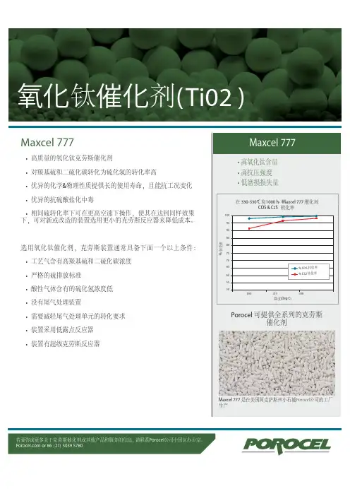
Maxcel 777
• 高质量的氧化钛克劳斯催化剂
• 对羰基硫和二硫化碳转化为硫化氢的转化率高
• 优异的化学&物理性质提供长的使用寿命,且能抗工况变化
• 优异的抗硫酸盐化中毒
• 相同硫转化率下可在更高空速下操作,使其在达到同样效果
下,可对新或改造的装置选用更小的克劳斯反应器来降低成本。
选用氧化钛催化剂,克劳斯装置通常具备下面一个以上条件:
• 工艺气含有高羰基硫和二硫化碳浓度
• 严格的硫排放标准
• 酸性气体含有的硫化氢浓度低
• 没有尾气处理装置
• 需要减轻尾气处理单元的转化要求
• 装置采用低露点反应器
• 装置有超级克劳斯反应器
Maxcel 777 是在美国阿克萨斯州小石城Porocel公司的工厂
生产
若要咨询更多关于克劳斯催化剂或其他产品和服务的信息,请联系Porocel公司中国区办公室。
or 86(21)5039 5780。

1、前言达克罗(Dacromet)技术诞生于20世纪70年代初,是美国Diamond Shamrock公司为解决由融雪盐引起的汽车锈蚀问题而研制的一种全新的金属防腐系统。
与传统的电镀、热浸镀等工艺相比,达克罗涂层具有高耐蚀性、高耐热性、高耐候性、无氢脆、与环境友好等优点,自问世以来,在许多工业部门包括在汽车的防腐中得到了广泛应用。
目前,世界上、许多汽车公司如德国大众、美国通用、福特、戴姆勒-克莱斯勒、韩国现代以及日本丰田、日产、本田、三菱等均已采用达克罗技术,并明确规定某些零件只能采用达克罗涂层防腐。
除普通钢制件外,达克罗涂层还可用于铸铁、粉末冶金材料、铝合金等零件的表面防腐处理。
达克罗技术的应用,大大延长了汽车的使用寿命。
在多年的应用中,各汽车公司已逐步形成了达克罗技术的处理规范和涂层质量检测标准,如大众的TL245、TL193,TL233,通用的GME 0025-F,福特的WSD-M2 1P11-B1等标准。
2、达克罗涂层的防腐机理达克罗涂层主要由鳞片状锌片、铝片以及无定形复合铬酸盐聚合物(nCrO3,mCr203)组成。
金属片在基体表面层层叠加,铬酸盐聚合物填塞在金属片之间,并通过树脂固化反应,使金属片之间以及金属片与基体牢固地粘结在一起,形成一种特殊的片状交错叠层结构。
达克罗涂层对基体的保护作用主要体现在以下3个方面。
a.机械屏蔽作用达克罗涂层的交错叠层结构本身就是一个非常有效的机械阻卜挡层,而且.絮状无定形的铬酸盐聚合物填塞在金属片之间,大大减少了涂层的空隙率,使涂层更为致密。
此外,锌的腐蚀产物与空气中的CO2反应,生成不溶于水的碳酸锌,不断恢复其机械阻挡功能。
因此,达克罗涂层能在零件表面形成良好的机械屏蔽层,使腐蚀介质很难找到进人金属基体的通道。
b.自钝化作用锌、铝金属片与铬酸发生化学反应,在各自表面生成致密的钝化膜,并通过无机盐粘结在一起,使整个涂层完全由带有钝化膜的铝、锌片紧密叠加而成,形成“超厚”钝化膜。
丝网:wire mesh玻璃纤维网(网格布):fiber-glass-mesh电焊网:welded wire mesh六角网:hexagonal wire mesh窗纱:window screening轧花网:crimped wire mesh勾花网:chain link mesh石笼网(格宾网):gabion mesh黄铜丝网:Brass Wire Cloth荷兰编织网:Dutch Woven Wire金属板网(扩张金属网):Expanded Metal Cloth镀锌铁丝网:Galvanized Iron Wire六角网:Hexagonal Wire Cloth镍丝网:Nickel Wire Cloth尼龙网:Nylon Wire Cloth塑料平网:Plastic Flat Mesh聚酯纤维网:Polyester Wire ClothPVC涂塑网:PVC Coated Wire Mesh不锈钢丝布:Stainless Steel Wire Cloth不锈钢丝:Stainless Steel Wire窗纱:Window Screen 窗纱丝径:wire diameter BWG SWG经丝:line wire/ warp wire纬丝:weft wire /cross wire孔径(网孔大小):aperture材质:material不锈钢:stainless steel/SS抗腐蚀:rust-resistance涂层:coated用途:End Usages抗化学品能力:Chemical Resistance镀铝(硅)钢片–日工标准(JIS G3314):Hot-aluminum-coated sheets and coils to JIS G 3314 镀铝(硅)钢片–美材试标准(ASTM A-463-77)35.7 JIS G3314镀热浸铝片的机械性能:Mechanical Properties of JIS G 3314 Hot-Dip Aluminum-coated Sheets and Coils公差:Size Tolerance镀铝(硅)钢片及其它种类钢片的抗腐蚀性能比较:Comparsion of various resistance of aluminized steel & other kinds of steel镀铝(硅)钢片生产流程:Aluminum Steel Sheet, Production Flow Chart焊接能力:Weldability镀铝钢片的焊接状态(比较冷辘钢片) :Tips on welding of Aluminized sheet in comparasion with cold rolled steel strip钢板:Steel Plate钢板用途分类及各国钢板的工业标准包括日工标准及美材试标准:Type of steel Plate & Related JIS, ASTM and Other Major Industrial Standards钢板生产流程:Production Flow Chart钢板订货需知:Ordering of Steel Plate不锈钢:Stainless Steel不锈钢的定义:Definition of Stainless Steel不锈钢之分类,耐腐蚀性及耐热性:Classification, Corrosion Resistant & Heat Resistance of Stainless Steel铁铬系不锈钢片:Chrome Stainless Steel马氏体不锈钢:Martensite Stainless Steel低碳马氏体不锈钢:Low Carbon Martensite Stainless Steel含铁体不锈钢:Ferrite Stainless Steel镍铬系不锈钢:Nickel Chrome Stainless Steel释出硬化不锈钢:Precipitation Hardening Stainless Steel铁锰铝不锈钢:Fe / Mn / Al / Stainless Steel不锈钢的磁性:Magnetic Property & Stainless Steel不锈钢箔、卷片、片及板之厚度分类:Classification of Foil, Strip, Sheet & Plate by Thickness 表面保护胶纸:Surface protection film不锈钢片材常用代号:Designation of SUS Steel Special Use Stainless表面处理:Surface finish薄卷片及薄片(0.3至 2.9mm厚之片)机械性能:Mechanical Properties of Thin Stainless Steel(Thickness from 0.3mm to 2.9mm) –strip/sheet不锈钢片机械性能(301, 304, 631, CSP):Mechanical Properties of Spring use Stainless Steel不锈钢–种类,工业标准,化学成份,特点及主要用途:Stainless Steel –Type, Industrial Standard, Chemical Composition, Characteristic & end usage of the most commonly used Stainless Steel不锈钢薄片用途例:End Usage of Thinner Gauge不锈钢片、板用途例:Examples of End Usages of Strip, Sheet & Plate不锈钢应力退火卷片常用规格名词图解:General Specification of Tension Annealed Stainless Steel Strips耐热不锈钢:Heat-Resistance Stainless Steel镍铬系耐热不锈钢特性、化学成份、及操作温度:Heat-Resistance Stainless Steel铬系耐热钢:Chrome Heat Resistance Steel镍铬耐热钢:Ni - Cr Heat Resistance Steel超耐热钢:Special Heat Resistance Steel抗热超级合金:Heat Resistance Super Alloy耐热不锈钢比重表:Specific Gravity of Heat –resistance steel plates and sheets stainless steel 不锈钢材及耐热钢材标准对照表:Stainless and Heat-Resisting Steels发条片:Power Spring Strip发条的分类及材料:Power Spring Strip Classification and Materials上链发条:Wind-up Spring倒后擦发条:Pull Back Power Spring圆面("卜竹")发条:Convex Spring Strip拉尺发条:Measure Tape魔术手环:Magic Tape魔术手环尺寸图:Drawing of Magic Tap定型发条:Constant Torque Spring定型发条及上炼发条的驱动力:Spring Force of Constant Torque Spring and Wing-up Spring定型发条的形状及翻动过程:Shape and Spring Back of Constant Torque Spring定型发条驱动力公式及代号:The Formula and Symbol of Constant Torque Spring边缘处理:Edge Finish硬度:Hardness高碳钢化学成份及用途:High Carbon Tool Steel, Chemical Composition and Usage每公斤发条的长度简易公式:The Length of 1 Kg of Spring Steel StripSK-5 & AISI-301 每公斤长的重量/公斤(阔100-200公厘) Weight per one meter long (kg) (Width 100-200mm)SK-5 & AISI-301 每公斤之长度(阔100-200公厘) Length per one kg (Width 100-200mm)SK-5 & AISI-301 每公尺长的重量/公斤(阔2.0-10公厘):Weight per one meter long (kg) (Width 2.0-10mm)SK-5 & AISI-301 每公斤之长度(阔2.0-10公厘):Length per one kg (Width 2.0-10mm)高碳钢片:High Carbon Steel Strip分类:Classification用组织结构分类:Classification According to Grain Structure用含碳量分类–即低碳钢、中碳钢及高碳钢:Classification According to Carbon Contains 弹簧用碳钢片:CarbonSteel Strip For Spring Use冷轧状态:Cold Rolled Strip回火状态:Annealed Strip淬火及回火状态:Hardened & Tempered Strip/ Precision –Quenched Steel Strip贝氏体钢片:Bainite Steel Strip弹簧用碳钢片材之边缘处理:Edge Finished淬火剂:Quenching Media碳钢回火:Tempering回火有低温回火及高温回火:Low & High Temperature Tempering高温回火:High Temperature Tempering退火:Annealing完全退火:Full Annealing扩散退火:Diffusion Annealing低温退火:Low Temperature Annealing中途退火:Process Annealing球化退火:Spheroidizing Annealing光辉退火:Bright Annealing淬火:Quenching时间淬火:Time Quenching奥氏铁孻回火:Austempering马氏铁体淬火:Marquenching高碳钢片用途:End Usage of High Carbon Steel Strip冷轧高碳钢–日本工业标准:Cold-Rolled (Special Steel) Carbon Steel Strip to JIS G3311 电镀金属钢片:Plate Metal Strip简介:General电镀金属捆片的优点:Advantage of Using Plate Metal Strip金属捆片电镀层:Plated Layer of Plated Metal Strip镀镍:Nickel Plated镀铬:Chrome Plated镀黄铜:Brass Plated基层金属:Base Metal of Plated Metal Strip低碳钢或铁基层金属:Iron & Low Carbon as Base Metal不锈钢基层金属:Stainless Steel as Base Metal铜基层金属:Copper as Base Metal。

第六代水性金属免除锈防腐漆久江水性金属免除锈防腐漆,是本公司以美国特殊的进口自除锈防腐蚀树脂为主要原料,配以美国进口的多种除锈助剂及防锈材料精致而成,专门针对化工行业和沿海地区的企业研发的水性环保型带锈、除锈的重防腐漆。
本防锈漆用于未经处理的金属表面防锈,对已锈蚀的金属件,可免除打磨、酸洗、磷化、抛丸等复杂的除锈工程,减少施工工序、材料和人工成本,极大地提高涂装工效。
给企业节省了巨额成本,又提高了防腐效果。
除锈,防腐,底漆一遍即成!水性体系,低气味,极低VOC,不燃、不爆、安全、无污染。
本漆粘度低,易涂刷,对已生锈的未经预处理的钢铁表面提供长久高效的保护,防锈漆能渗入锈层与锈点产生化学反应,转化为微黑色防锈膜,涂刷几分钟后与金属表面的锈蚀发生化学反应,即转化得到一层坚韧、致密的黑色惰性保护层,是基于新的化学螯合将表面的锈蚀转化为疏水钝化层,其膜层在金属表面形成牢固致密的保护膜、紧紧贴在钢材上,隔绝水气、氧及其它腐蚀因子的侵蚀。
并为金属表面的活性基团反应而“键合”具有优良的防腐蚀性能,应用金属表面的装饰与保护。
使得金属材料表面呈“疏水性”,同时涂层材料可与金属表面以化学键相结合,极大地增强了涂膜的附着力和防腐性能,具有优异的抗再锈蚀性能,是理想的环保防腐涂料。
和传统体系相比,该免除锈防腐蚀系统在再次锈蚀发生之前提供更长久的保护。
施工要求:1、施工前要清除干净金属钢件表面的灰尘污物,特别要彻底清洗干净表面的机油油污,因机油与水性漆不相融,会隔绝防锈漆渗入基层,造成与基材分层,影响附着力。
(特别是新钢件管材表面的防锈油脂、旧设备表面油污及夹缝的机油黄油),对锈蚀极严重的金属表面,如果已形成锈片,要先清除后再涂刷,用风吹净或用水洗净残留的锈尘再施工。
2、可用刷涂、喷涂、浸涂或辊涂的方法施工于干的或潮湿的金属表面。
最好的方法是用刷涂的方法以提供更高的渗透性。
和绝大多数水性涂料一样,不应于5℃以下施工。
在涂层干燥期间,应避免有结露或下雨情况。
英文回答:Bremstone, as amon silicate mineral, has extensive applications in surface protective material。
Its superior chemical stability and resistance make it an ideal additive to paint, paint and waterproof materials in the construction field to enhance the durability and corrosivity of materials。
Bomstone is also often used in the manufacture of glass and ceramic materials to achieve surface resistance and durability。
The application of Bomstone in surface—protective materials helps to improve the performance of materials and to extend their useful life, in line with our current needs for building materials and our national development strategy。
勃姆石,作为一种常见的硅酸盐矿物,在表面防护层材料中具有广泛的应用。
其优异的化学稳定性和耐磨性使其成为建筑领域中涂料、油漆和防水材料的理想添加剂,以增强材料的耐久性和抗腐蚀性。
勃姆石也常被用于制造玻璃和陶瓷材料,以实现表面的抗污染和耐用性。
勃姆石在表面防护层材料中的应用,有助于改善材料的性能,并延长材料的使用寿命,符合当前我国建筑材料需求和国家发展战略。
2021年1月Jan.2021第35卷第1期(总第135期)Vol.35No.1(Sum.No.135)桂林师范高等专科学校学报Journal of Guilin Normal College胡萝卜水热法一步合成荧光生物质碳点用于细胞成像杨克琴(桂林师范高等专科学校化学与药学系,广西桂林541199)摘要:荧光碳点由于其优异的光学和化学性能,近年来引起了人们的广泛关注。
本研究以天然生物质胡萝卜为原料,通过水热法一步合成了粒径均匀的荧光生物质碳点(BCDs)。
制备过程简单环保,所合成的荧光BCDs具有良好的耐光漂白能力和生物相容性,并成功应用于人膀胱癌活细胞荧光成像中。
关键词:胡萝卜;生物质碳点;细胞成像中图分类号:0613文献标识码:A—、弓I言荧光碳点(CDs)是一种粒径小于10nm 的新的零维碳纳米材料[1],在2004年由Xu团队在合成单壁碳纳米管的过程中首次发现叫近年来,由于CDs具有独特的荧光特性、光学稳定性、毒性低、良好的生物相容性、尺寸小以及制备成本低等优点[3,4]而受到广泛的关注。
传统的半导体量子点由于在制备过程中常掺杂镉、铅等重金属,存在较高的细胞毒性,限制了其在生物学中的应用叫与传统的半导体量子点比较,CDs具有原材料来源广泛、制备简单、价格低廉等长处。
CDs主要由碳、氢、氧等元素构成,细胞毒性较低[6],能克服有机荧光染料的易光漂白和发光不稳定等缺点[7]o作为一种多功能的碳纳米材料,文章编号:1001-7070(2021)01-0086-06CDs凭借其良好的生物相容性、较好的光稳定性、良好的水溶性以及低细胞毒性等优点被广泛应用于生物成像、生物传感及药物输送等领域[8-10],并且已经替代了传统的半导体量子点,成为一种新型生物标记试剂。
因此,绿色合成发光性能好的CDs并将其应用在生物或分析化学等领域,是非常有意义的。
本文以生物质胡萝卜为原料,通过水热法一步合成了一种绿色的荧光生物质碳点BCDs,该BCDs在495nm处有很强的荧光发射峰。
Engineered CoatingsISO9001 CERTIFIED MANUFACTURING 248-647-4500This document may contain confidential and privileged information. Copyright 2013 © The Magni Group, Inc. All rights reserved.Performance Data:Military Specifications:Other Specifications:4-2013MAGNI 565 MilitaryMagni 565 is a chrome free duplex fastener coating system that combines an inorganic zinc-rich basecoat with an aluminum-rich organic topcoat.Magni 565 has been formulated as a two-coat system, providing a cost advantage while maintaining superior corrosion resistance. Friction modifiers are integrated into the Magni 565 topcoat, providing repeatable torque tension characteristics during assembly.Magni 565 is designed for use on externally threaded fasteners, stampings and other types of hardware. This product can be applied via dip-spin or spray and is available in a variety of colors. Magni 565 is currently the preferred finish on fasteners at many automotive manufacturers.M A G N I 565 Amonix 90400026 Arvin Meritor P91 ASTM A490, F2833 Grade 1 BAE 3000009 Bobcat PS-106A B M W GS90010 Briggs & Stratton Brose BN590295-106 Case New Holland MAT0320, Type 1, Class A Chrysler PS-5873 (ref: PS-10633 non-threaded), PS-10633, PS-10378 Cummins 74045 Daimler-Benz DBL 8440 .20/.22 Delphi DX551801, DX45501804, DX551810, DX44501804 Denso DDS6700-008 DF3-BT Dometic 12-67 E2 Fiat 9.57513/Tipo IV Ford S439 (WSS-M21P37-A1) GE F69A4 General Motors GM7114M, GMW3359 Honda HES D2008-1 ISO 10683 JLG 4150701 John Deere JDM F13 Land Rover LRES.21.ZS.05 Navistar TMS-4518, Type I Nissan M 4601 Porsche PTL 7529PSA B15 3320 Renault Trucks 01.71.4002/H Tacom/US Army 12469117 Trane S 3201063A1 TRW TS 2-25-60, Class A Volkswagen TL 233 Ofl-t330/Ofl-t350/Ofl-t650 Volvo VCS5737.29, .19 Arvin Meritor P91 BAE 3000099 Case New Holland MAT0320, Type 1, Class A JLG 4150701 Navistar TMS-4518, Type I Tacom/US Army 12469117 Textron Land & Marine MS16998-M Chrome-FreeSalt Spray 1000 Hours ASTM B117 Cyclic Corrosion Resistance GM9540P 60 cycles SAEJ2334 120 cycles Volvo VCS 1027,149 tbdCoefficient of Friction 0.13 (other levels available) Coefficient of Friction Tested per ISO 16047 +.03 Coating Thickness 13 microns No Hydrogen Embrittlement Concerns Excellent Bi-Metallic Corrosion Resistance Heat Resistance 250o F (long term) 500o F (short term)Resistant to Automotive Fuels and Fluids Paintable RoHS, WEEE, and ELV Compliant。
专利名称:Braze-metal coated articles and process formaking same发明人:Steven W. Webb,Gaurav Aggarwal申请号:US12287123申请日:20081006公开号:US20090092823A1公开日:20090409专利内容由知识产权出版社提供专利附图:摘要:In one embodiment, a carbide-containing article includes a carbide body with an attached optional superabrasive layer. A braze metal coating is attached to a surface the carbide substrate. The coating primarily is made of particles of a metal having a meltingpoint of less than 1200° C., the particles having a size of less than 0.1 mm. In another embodiment, a process for applying a braze metal coating to a carbide body of a superabrasive or other article includes depositing finely divided particles of a low melting point metal onto the carbide body by spraying the particles and gas onto the body at a velocity that is between 500 km/sec and 2 km/sec, with volumetric delivery of the particles being less than 50 grams per minute.申请人:Steven W. Webb,Gaurav Aggarwal地址:Worthington OH US,Columbus OH US国籍:US,US更多信息请下载全文后查看。
专利名称:Noble metal alkali borosilicate glasscomposition发明人:Pedro M. Buarque de Macedo申请号:US11893257申请日:20070814公开号:US20080045398A1公开日:20080221专利内容由知识产权出版社提供专利附图:摘要:An embodiment of the present invention comprises a ceramic catalystcomprising a porous ceramic/silica glass substrate having substantially interconnecting pores with an average pore size of approximately 2 micron or less and particlescomprising one or more noble metals on the surface of the substantially interconnecting pores. The noble metal particles may be either amorphous and/or crystalline nano-particles. The noble metals preferably may comprise silver, gold, rhodium, and/or palladium. The average pore size may be approximately 1 micron or less, 0.5 microns or less, 0.3 microns or less, 0.2 microns or less, 100 nanometers or less, 50 nanometers or less, or between 50 nanometers and 150 nanometers. Other embodiments of the present invention are directed to methods of manufacturing the ceramic catalyst and novel glass compositions used to manufacture the ceramic catalyst and using the ceramic catalyst at temperatures above 200° C. to produce hydrogen gas and to store hydrogen gas.申请人:Pedro M. Buarque de Macedo地址:Bethesda MD US国籍:US更多信息请下载全文后查看。
Chinese Journal of Catalysis 41 (2020) 227–241催化学报 2020年 第41卷 第2期 | a v a i l ab l e a t w w w.sc i e n c ed i re c t.c o mj o u r n a l h o m e p a g e : w w w.e l s e v i e r.c o m /l o c a t e /c h n j cReviewApplication of atomic layer deposition in fabricating high-efficiency electrocatalystsHuimin Yang a , Yao Chen b , Yong Qin a,*a State Key Laboratory of Coal Conversion, Institute of Coal Chemistry, Chinese Academy of Sciences, Taiyuan 030001, Shanxi, China bSchool of Life Sciences, Northwestern Polytechnical University, Xi’an 710072, Shaanxi, ChinaA R T I C L E I N F OA B S T R A C TArticle history:Received 17 May 2019 Accepted 5 July 2019Published 5 February 2020Electrocatalysis is a promising approach to clean energy conversion due to its high efficiency and low environmental pollution. Noble metal materials have been studied to show high activity toward electrocatalyltic reactions, although such applications remain restricted by the high cost and poor durability of the noble metals. By precisely adjusting the catalyst composition, size, and structure, electrocatalysts with excellent performance can be obtained. Atomic layer deposition (ALD) is a technique used to produce ultrathin films and ultrafine nanoparticles at the atomic level. It pos-sesses unique advantages for the controllable design and synthesis of electrocatalysts. Furthermore, the homogenous composition and structure of the electrocatalysts prepared by ALD favor the ex-ploration of structure-reactivity relationships and catalytic mechanisms. In this review, the mecha-nism, characteristics, and advantages of ALD in fabricating nanostructures are introduced first. Subsequently, the problems associated with existing electrocatalysts and a series of recently devel-oped ALD strategies to enhance the activity and durability of electrocatalysts are presented. For example, the deposition of ultrafine Pt nanoparticles to increase the utilization and activity of Pt, fabrication of core–shell, overcoat, nanotrap, and other novel structures to protect the noble-metal nanoparticles and enhance the catalyst stability. In addition, ALD developments in synthesizing non-noble metallic electrocatalysts are summarized and discussed. Finally, based on the current studies, an outlook for the ALD application in the design and synthesis of electrocatalysts is pre-sented.© 2020, Dalian Institute of Chemical Physics, Chinese Academy of Sciences.Published by Elsevier B.V. All rights reserved.Keywords:Atomic layer deposition Electrocatalysis PtCatalyst stabilityMetal-support interaction1. IntroductionWith the increase in energy demands and the reduction in non-renewable fossil fuels, humanity is facing a severe energy crisis [1,2]. Developing sustainable and clean pathways to pro-duce chemicals and fuels is vital for meeting human energy requirements and protecting the environment. Electrocatalysis is a promising method for clean energy conversion. It is able toconvert molecules in the atmosphere, such as H 2O, CO 2, and N 2, into higher-value H 2, hydrocarbons, oxygenates, and NH 3 products by coupling to clean electric energy [3–7]. Additional-ly, it can convert the chemical energy of fuels, including H 2, methanol, ethanol, and formic acid, directly into electrical en-ergy via an efficient and clean mechanism compared to the case with other power generation methods and allows for a diverse range of applications in portable and transportation power* Corresponding author. Tel: +86-351-4040081; E-mail: qinyong@This work was supported by the National Natural Science Foundation of China (21872160, 21802094, 21673269), the National Science Fund for Distinguished Young Scholars (21825204), the National Key R&D Program of China (2017YFA0700101), and the Natural Science Basic Research Plan in Shaanxi Province of China (2018JQ2038).DOI: S1872-2067(19)63440-6 | /science/journal/18722067 | Chin. J. Catal., Vol. 41, No. 2, February 2020228Huimin Yang et al. / Chinese Journal of Catalysis 41 (2020) 272–241generation [8–10].Electrocatalysts are crucial in these energy conversion technologies for increasing the rate and selectivity of the chemical transformations involved. Pt-based catalysts have been proven to exhibit high activity in many important elec-trochemical reactions, such as the hydrogen evolution reaction (HER), oxygen evolution reaction (OER), oxygen reduction re-action (ORR), and electrooxidation of small-molecule alcohols and acids [5,8–11]. However, large-scale commercialization of Pt-based catalysts is restricted by the low abundance and high price of the Pt noble metal. In addition, Pt-based electrocata-lysts are confronted with instability. Pt nanoparticles are usu-ally loaded on carbon supports with a high surface area and good conductivity to provide more active sites and improve the Pt utilization. However, carbon materials are prone to be oxi-dized to CO2 under the severe conditions of the electrochemical environment, such as high humidity, high potentials, and high oxygen concentrations. The corrosion of carbon supports can induce the detachment and agglomeration of Pt nanoparticles and the subsequent degradation of the Pt catalytic activity. The weak interaction between Pt and carbon supports also leads to the migration and coalescence of Pt nanoparticles. Further-more, in the electrooxidation of methanol, ethanol, formic acid, etc., the intermediate products, e.g., CO, can be strongly ad-sorbed on the surface of Pt and result in catalyst poisoning. Therefore, the development of electrocatalysts with both high activity and stability is imperative.Intensive efforts have been devoted to enhancing the cata-lytic properties of Pt electrocatalysts. Reducing the size of Pt to small nanoparticles, clusters or even single atoms can expose more Pt active sites per unit mass, thus significantly increasing the catalyst activity and improving Pt utilization. Pt clusters below 0.5 nm loaded on graphene nanosheets exhibited an extremely higher activity toward methanol electrooxidation in comparison with that of a commercial 20 wt.% Pt/C black cat-alyst [12]. Pt single atoms showed a 4-times-higher mass activ-ity toward the HER than that of commercial Pt/C [11]. Mean-while, manufacturing core-shell structures with Pt as the shell and a second metal as the core can also decrease the Pt usage and enhance the catalytic properties. The composition of core–shell nanoparticles and the thickness of the Pt shell sig-nificantly affect the catalyst activity. Pt-Pd core-shell nanopar-ticles with a shell thickness of one monolayer of Pt exhibited a 5-fold activity enhancement toward the ORR over that of monometallic Pt nanoparticles. The improved catalytic activity of this core-shell structure originated from the nanosize- and mismatch-induced surface contraction, which weakened the oxygen binding energy on the Pt surface and facilitated the ORR process [13].To inhibit the migration and agglomeration of Pt nanoparti-cles and improve the stability of Pt electrocatalysts, materials more corrosion-resistant than carbon black, e.g., ZrC, SiC, TiO2, and TiB2, have been utilized as catalyst supports [14–17]. In-creasing the interaction between Pt and the support can also help to stabilize the Pt nanoparticles. Studies have shown that doping carbon supports with heteroatoms such as sulfur, ni-trogen, or phosphorus can effectively stabilize Pt nanoparticles [18–20]. Pt catalysts incorporated with metal oxide supports exhibit enhanced electrocatalytic activity and stability due to the strong metal-support interactions [21–23]. For example, a strong metal-support interaction led to a Pt–O bond formation between Pt clusters and TiO2and ultrahigh stability of Pt na-noparticles. The synthesized Pt/TiO2 catalyst lost only 5.6% of its initial activity toward the HER, while the commercial Pt/C lost 27.9% of its initial activity after the accelerated degrada-tion tests [15]. Encapsulation of Pt nanoparticles in a metal oxide is also an effective way to stabilize Pt catalysts, while the content and structure of the metal oxide should be carefully modulated [24].Notwithstanding these advancements, it is still challenging to precisely control the constituent, size, and morphology of electrocatalysts to achieve the desired activity and stability using traditional methods. Atomic layer deposition (ALD) pro-duces ultrathin films or ultrafine nanoparticles through succes-sive and alternative surface reactions between gaseous pre-cursors and a substrate surface [25,26]. The self-limiting nature of ALD makes it possible to deposit conformal and uniform films or nanoparticles on high-aspect-ratio structures, and the film thickness and particle size can be controlled at the atomic level [27]. ALD for electrocatalyst synthesis has been rapidly developed in the past few years. In this review, state-of-the-art developments in ALD applications toward the design and syn-thesis of electrocatalysts are presented. Firstly, some funda-mental studies on ALD are given. Based on these studies, dif-ferent strategies for improving the efficiency and stability of noble metal Pt electrocatalysts are discussed. Secondly, the synthesis of desirable noble bimetallic electrocatalysts via the ALD method, particularly bimetallic electrocatalysts with a core-shell structure is introduced. Lastly, the ALD production of non-noble metal electrocatalysts, such as transition metal ox-ides, nitrides, sulfides, and carbides is demonstrated.2. Noble monometallic Pt electrocatalysts2.1. The mechanism of Pt ALDUnderstanding the ALD mechanism can help to better con-trol the deposition and obtain materials with desirable mor-phologies and structures. Pt ALD represents a typical metal ALD. Here, we adopt Pt ALD as an example to briefly introduce the ALD mechanism. During the Pt ALD process, two kinds of substances participate in the reactions: Pt organometallic pre-cursor and counter reactant. Taking the reaction of (methylcy-clopentadienyl)trimethylplatinum (MeCpPtMe3) and O2as a model, the Pt ALD process contains the following steps. (i) The substrate is exposed to the MeCpPtMe3vapor, and the MeCpPtMe3 molecules react with the oxygen functional groups on the substrate surface. The ligands of MeCpPtMe3are par-tially oxidized, producing H2O and CO2 as byproducts. The reac-tion stops when the oxide groups on the substrate surface are depleted. (ii) The unreacted precursor molecules and byprod-ucts are purged by an inert gas. (iii) The substrate is exposed to O2. The Pt precursor molecules chemisorbed on the substrate surface are completely oxidized, and Pt atoms are produced.Huimin Yang et al. / Chinese Journal of Catalysis 41 (2020) 227–241 229Meanwhile, a new layer of oxygen functional groups is formed on the surface of Pt (Fig. 1). By alternatingly exposing the sub-strate to MeCpPtMe 3 and O 2, the two reactions proceed indi-vidually and terminate automatically once the surface reactive sites are consumed. By repeating the above steps, Pt is depos-ited on the surface of the substrate [28–30]. At the initial stage of ALD, the Pt nanoparticles undergo island growth owing to their weak infiltration between the Pt precursor and substrate or to the limited number of active sites on the substrate surface. When conducting further ALD cycles, the Pt nanoparticles coa-lesce and form a continuous Pt film. Owing to the self-limiting nature of ALD, the size of the Pt particles and the thickness of the Pt film can be controlled at the atomic level by adjusting the number of ALD cycles.2.2. The effect of carbon supports on the ALD processCarbon materials with good conductivity and high specific surface area are suitable and widely applied supports for elec-trocatalysts. Though Pt, Pd, and some other metal nanoparticles have been successfully deposited on carbon materials to pro-duce high-efficiency electrocatalysts, pristine carbon supports are actually unfavorable for ALD owing to the absence of func-tional groups [32–34]. Here, functional groups refer to some oxygen-containing groups and ionic species on the substrate surface. They play a vital role since nucleation occurs at these active sites upon initiation of ALD. The chemically inert surfac-es of pristine carbon materials lack adequate functional groups, and this will result in nucleation delay and island growth when the ALD process is initiated [35–37].Increasing the number of functional groups on the surface of a carbon support can provide more active sites for the ALD nucleation and promote uniform deposition. A variety of methods to create functional groups on carbon supports has been reported. Hsueh et al. [37] found that an HNO 3 pretreat-ment could implant oxygen groups including ether (C–O), car-bonyl (C=O), and carboxyl (O–C=O) on the surface of the carbon nanotubes (CNTs). Subsequently, dense and uniform Pt nano-particles could be synthesized on the surface of the pretreated CNTs, while few Pt nanoparticles were formed on the surface ofpristine CNTs when applying the same number of Pt ALD cycles [38]. Perng et al. [39] discovered that the number of oxy-gen-containing functional groups on the surface of the CNTs could be increased by prolonging the acid treatment time. The authors deposited Pt nanoparticles via the ALD method on CNTs pretreated with nitric acid for 9 h and incorporated the synthesized Pt/CNT catalyst into a membrane electrode as-sembly (MEA). The MEA, composed of an ALD-deposited anode (with a Pt loading of 0.019 mg cm –2) and cathode (with a Pt loading of 0.044 mg cm –2), exhibited a specific power density in an H 2/O 2 PEMFC that was 11-times higher than that of the MEA composed of commercial Pt/C electrodes (with a Pt loading of 0.5 mg cm –2) [39]. Hsieh et al. [40] reported that the oxy-gen-containing functional groups on graphene oxide (GO) not only favored the dispersion of Pt nanoparticles but also facili-tated the oxidation of strongly adsorbed CO intermediates and the regeneration of poisoned Pt sites, thereby enhancing the activity and CO-resistance stability in the formic acid elec-trooxidation reaction. H 2SO 4, HClO 4, and citric acid can also be used to create oxygen-containing groups on the surface of car-bon supports [29,41,42].In addition to liquid-phase acid oxidation, gas-phase func-tionalization routes have been developed. Dameron et al. [43] functionalized CNT arrays using either molecular deposition to create a trimethylaluminum (TMA) monolayer, which could offer a chemical site that is more reactive with the Pt ALD pre-cursor, or O 2 plasma to increase the defect density and number of oxygen-containing functional groups on the surface of the CNTs. Both TMA and O 2-plasma treatments could facilitate Pt nucleation and accelerate the ALD growth rate [43]. Qin et al. [44] used O 3 as the counter reactant, instead of O 2, during the Pt ALD process, producing homogenous Pt particles on the surface of the CNTs. O 3 could in situ activate the CNT surface during the ALD reaction; thus, a pre-functionalization treat-ment could be omitted [44]. Pt ALD, with O 3 as the counter re-actant, exhibits a higher growth rate than that with O 2 [45]. The usage of O 3 can also result in a deposition temperature as low as 150 °C, whereas most Pt ALD experiments are conducted at 300 °C with O 2 as the counter reactant [45]. The low deposition temperature is suitable for substrates with poor thermostabil-ity.Doping carbon materials with nitrogen benefits the disper-sion of Pt nanoparticles as well [46,47]. Stambula et al. [48] synthesized N-doped graphene by heating graphene at 900 °C in an NH 3/Ar atmosphere. Diverse N-dopant species, consisting of amino, pyridinic, and pyrrolic dopants, infiltrated the gra-phene lattice by forming covalent bonds, while the basic struc-ture of graphene was preserved. The N-dopants helped to sta-bilize Pt; only single atoms and clusters (but no nanoparticles) of Pt were formed on the N-doped graphene, even after 150 cycles of Pt ALD [48].2.3. The metal–support interactions synthesized by ALD A strong metal–support interaction (SMSI) plays an im-portant role in enhancing the catalytic activity and stability by improving the charge redistribution between the metalandFig. 1. Schematic of the Pt ALD mechanism [31]. © Springer Nature Publishing AG 2013.230 Huimin Yang et al. / Chinese Journal of Catalysis 41 (2020) 272–241support [49]. This action usually occurs between a metal and oxide support, and it is achieved through a high-temperature treatment in a reducing atmosphere. However, high tempera-tures can induce the sintering of metal nanoparticles and also induce oxide migration onto the surface of the metal particles, thereby blocking the active catalytic sites on the surface of the metal [50].The weak interaction between Pt and carbon supports of the catalysts synthesized through conventional chemical re-duction methods is one of the reasons for the aggregation of the Pt nanoparticles and the consequent degradation of the Pt cat-alytic activity [24,51]. When synthesizing Pt catalysts by chem-ical reduction methods, Pt nanoparticles are firstly formed in a solution and subsequently attached to the surface of the sup-port mainly through physical adsorption. Whereas ALD-prepared metal catalysts are considered to possess a rela-tively strong interaction between the metal nanoparticles and the support. While using the ALD method, Pt precursor mole-cules adsorb on the surface of the support through strong chemical bonds, and the physically adsorbed precursor mole-cules are purged with inert gas. As the number of ALD cycles increases, Pt is produced layer by layer by chemical reactions between the precursor molecules and counter reactants; even-tually, nanoparticles are formed on the surface of the support. This method for growing Pt NPs contributes to the strong in-teraction between the metal and support (Fig. 2).Sun’s group [14] compared the Pt/ZrC catalysts synthesized by a conventional chemical reduction method (denoted as CW-Pt/ZrC) with those by the ALD method. It was found that the ALD-Pt nanoparticles were hemispherically shaped on the ZrC surface, and the lattices of Pt(111) and ZrC(111) were well matched, while the CW-Pt nanoparticles were spherically shaped on the ZrC surface. In addition, XANES showed that the Pt/ZrC catalysts prepared by the ALD method possessed a rela-tively high total unoccupied density of states with a Pt 5d char-acter. These results confirmed the existence of an enhanced interaction between the ALD Pt nanoparticles and ZrC. The strong metal–support interaction adjusted the Pt electronic state, resulting in intermediate binding energy for oxygen on the Pt surface, and finally contributed to an improved ORR ac-tivity. The strong interaction between Pt and ZrC for ALD-Pt/ZrC also helped to enhance the catalyst stability, with a 17% loss of initial electrochemical surface area (ECSA) on ALD-Pt/ZrC after accelerated durability tests, whereas the ECSA decreased by 52% and 78% for CW-Pt/ZrC and commer-cial Pt/C, respectively [14]. Saha et al. [52] investigated the metal–support interaction of an ALD-synthesized Pt/Mo 2C catalyst by surveying the lattice spacing of the crystal particlesby HRTEM. The lattice spacing was 0.26 nm for bare Mo 2C and 0.21 nm for Pt(111). On the ALD-synthesized Pt/Mo 2C, it was found that the Pt(111) fringes were expanded to 0.24 nm for small Pt particles. For relatively large Pt nanoparticles, the lat-tice spacing was approximately 0.21 nm in the center area, and it was expanded to 0.24 nm near the edge. This phenomenon of lattice expansion demonstrated the strong interaction between the ALD Pt and Mo 2C. The strong interaction between the metal and support in ALD-synthesized Pt/Mo 2C enhanced the cata-lytic activity and stability. The ALD Pt/Mo 2C catalyst with a 4.4% Pt loading exhibited a comparable HER activity to that of a commercial 20 wt.% Pt/C; no decrease in current density was observed for the Pt/Mo 2C ALD after the 48-h durability test, while the commercial Pt/C lost 24% of its initial current densi-ty [52].2.4. Pt electrocatalysts designed by ALD2.4.1. Fabricating highly active Pt electrocatalysts through ALD Improving the utilization of Pt is immensely required con-sidering the low abundance and high price of Pt. Decreasing the Pt particle size can provide more active sites, thus reducing the Pt usage and catalyst cost. Pt with a diameter ranging from those of single atoms to clusters and to nanoparticles has been deposited on various supports through ALD by simply adjust-ing the ALD cycle number. Hsieh et al. [29] synthesized highly dispersed Pt nanoparticles with an average diameter of ap-proximately 2.1 nm on a carbon powder (CP) support through ALD. The catalyst presented an ultralow Pt loading of 0.05 mg cm –2, nearly ten times less than that of commercial Pt/C (0.47 mg cm –2), but it exhibited a higher activity toward methanol electrooxidation and a better CO tolerance. The apparent acti-vation energies for both the dehydrogenation of methanol (I F , direct methanol oxidation pathway) and the oxidation of ad-sorbed CO intermediates (I B , indirect methanol oxidation pathway) were determined to be smaller on ALD-Pt than on commercial Pt/C, indicating a lower potential barrier on the ALD Pt/CP catalyst. This was ascribed to the small Pt particle size and oxidized Pt surface that effectively accelerated the dissociative adsorption of methanol and promoted the oxida-tion of CO intermediates adsorbed on Pt sites [29]. A sin-gle-atom Pt/graphene catalyst fabricated by ALD exhibited a dramatically improved methanol electrooxidation activity (ap-proximately 10 times higher than that of the state-of-the-art commercial Pt/C catalyst). X-ray absorption fine structure (XAFS) analyses ascribed this improvement to the low-coordination and partially unoccupied density of states of the 5d orbital of Pt atoms [31]. Single Pt atoms supported on N-doped graphene were also fabricated through ALD and ex-hibited a greatly enhanced HER activity (approximately 37 times higher) and high stability compared with those of the commercial Pt/C catalyst [18].Three-dimensional (3D) supports possess a large specific surface area and high porosity, which can offer a highly acces-sible electrochemical surface and facilitate mass and electron transfers during the electrocatalytic reactions. The usage ofmonolithic, porous, and conductive 3D supports can also pre-Fig. 2. Schematic of the ALD-Pt growth on a ZrC support [14]. © The Royal Society of Chemistry 2015.Huimin Yang et al. / Chinese Journal of Catalysis 41 (2020) 227–241231vent the addition of polymeric binders, surfactants, and other additives, which are required when preparing a catalyst coating for the electrode with a powder catalyst and which often cause problems of dead volumes, blocking of active sites, and ob-struction of mass and charge transfers. Depositing materials onto the inner surface of 3D supports with a high aspect ratio is challenging. It is difficult to create uniform particles or a con-tinuous thin film by solution deposition techniques, and the support collapses easily once the solution is removed. Chemical vapor deposition and sputter deposition techniques have lim-ited penetration into deep interior surfaces. ALD allows for the conformal and uniform coating of nanoparticles or thin films on complex 3D structures by employing saturated, self-limiting surface chemistry reactions. Nayak et al. [53] synthesized a Pt-based catalyst with a monolithic laser-scribed graphene scaffold (LSG) as a support through the ALD method. The SEM elemental mapping illustrated that the entire LSG was covered by uniform and conformal Pt nanoparticles. Owing to the ul-trafine and homogenous Pt nanoparticles, the ALD Pt/LSG cat-alyst with an ultralow loading of 0.04 mg cm–2, nearly an order of magnitude lower than that of commercial 10 wt.% Pt/C (0.5 mg cm–2), exhibited a very similar HER performance to that of the control [53]. Figure 3 illustrates the ultrafine and uniformly dispersed Pt particles deposited on various supports through the ALD method.In addition to nanoparticles, various nanostructures of Pt have been successfully synthesized through ALD and applied in electrochemical reactions. Bent et al. [55] deposited a uniform Pt film on a graphite surface using active O3 as the counter re-actant, whereas Pt was only deposited on the step edges of the graphite surface and formed Pt nanowires when O2 was used as the counter reactant. Cheng et al. [56] fabricated ordered hol-low Pt nanotube arrays (NTAs) by ALD using ZnO nanorod arrays as a template. The Pt NTAs presented improved metha-nol electrooxidation activity and CO tolerance in comparison with those of a commercial Pt/C catalyst owing to the 3D po-rous hollow structures and abundant Pt active sites [56]. A robust 3D porous Pt structure was created by initially deposit-ing Pt on a zeolite and subsequently digesting the silica tem-plate using hydrogen fluoride. The fully connected Pt structures exhibited significant impedance improvement and remarkable HER performance in comparison with those of the reference Pt electrodes [57].2.4.2. Enhancing the stability of Pt electrocatalysts by the ALD methodPt nanoparticles undergo dissolution and coalescence under severe electrochemical conditions, resulting in the reduction of their active specific surface and catalytic activity. Different strategies have been developed to improve the stability of Pt electrocatalysts. Overcoating a conformal oxide or carbon film can help stabilize metal nanoparticles from migration and ag-glomeration. However, poor film layers cover the catalyst sur-face and increase the mass transfer resistance, resulting in the loss of catalytic activity. ALD has been studied as a powerful method to deposit protective overcoats since the composition and thickness of the overcoating films can be precisely con-trolled at the atomic level to minimize the mass transport re-sistance. Lu et al. [58] discovered that 1–16 cycles of Al2O3 ALD on Pd remarkably inhibited the sintering of the metal nanopar-ticles without decreasing the catalyst activity toward methanol decomposition reaction. Within 16 cycles of ALD, Al2O3 prefer-entially nucleated and grew at the edges and corners of Pd, which were not active catalytic active sites for the reaction. Increasing the ALD cycles induced the gradual coverage of ac-tive catalytic Pd(111) sites and the degradation of the catalyst activity. Upon conducting 32 and more Al2O3 ALD cycles, the Pd nanoparticles were completely encapsulated and deactivated [58].When depositing protective overcoat films, it is crucial to create pores within the ALD overcoat to allow the reagents access the metal particles. Several methods have been pro-posed to generate and control the porosity within ALD films.(i) High-temperature treatment. By removing the ALD-derived carbon residues and excluding the dehydration effect, pores can be generated within oxide films after high-temperature treatment. For example, new pores with diameters of approximately 2 nm were generated in an ALD Al2O3 overcoat after treatment at 700 °C for 2 h in 10% O2/He. CO DRIFTS showed that by increasing the temperature of the heat treatment from 500 to 700 °C, the intensity of the CO chemisorption peaks on Pd gradually increased, indicating that a more porous structure was generated to provide access to the Pd sites for the reagent [59]. Porous carbon films can be ob-tained by carbonizing organic polymer films at a high temper-ature in an inert or H2 atmosphere. Qin et al. [47] overcoated porous N-doped carbon films on a Pt/CNT catalyst by carbon-izing ALD polyimide films at 600 °C for 2 h in 5% H2/N2. The activity and stability of the catalyst toward methanol elec-trooxidation were remarkably enhanced due to the protective effect of the overcoated porous carbon films [47].Fig. 3. (a) TEM images of ultrafine and uniform Pt nanoparticles depos-ited via ALD on 1D CNTs [54]. © The Royal Society of Chemistry 2017.(b) 2D graphene [31]. © Springer Nature Publishing AG 2013. (c) Cross-sectional SEM images of a 3D graphene scaffold and (d) its cor-responding elemental mapping image for Pt [53]. © The Royal Society of Chemistry 2017.。
Noble Metal Coated Single-Walled Carbon Nanotubes for Applications in Surface Enhanced Raman Scattering Imaging and Photothermal TherapyXiaojing Wang,†Chao Wang,†Liang Cheng,†Shuit-Tong Lee,‡and Zhuang Liu*,††Jiangsu Key Laboratory for Carbon-Based Functional Materials&Devices,Institute of Functional Nano&Soft Materials Laboratory (FUNSOM),Soochow University,Suzhou,Jiangsu215123,China‡Center of Super-Diamond and Advanced Films(COSDAF)and Department of Physics and Materials Science,City University of Hong Kong,Hong Kong SAR,China*Supporting Informationthe excitation source,targeted Raman imaging of cancernanocomposite(SWNT-Au-PEG-FA)is realized,with images acquirednonenhanced SWNT Raman probes.Owing to the strongshell,the SWNTs-Au-PEG-FA nanocomposite also offerswork presents a facile approach to synthesize water-solublelabeling and fast Raman spectroscopic imaging of biologicalnanocomposite developed here may thus be an interestingINTRODUCTIONCarbon nanotubes,especially singe-walled carbon nanotubes (SWNTs),have attracted significant interest in the area of biomedicine,for potential applications in biological detection, drug delivery,phototherapies,and biomedical imaging.1−7 Owing to their unique one-dimensional(1-D)structure, SWNTs exhibit strong resonance Raman scattering due to their sharp electronic density of states at the van Hove singularities.1SWNTs have several distinctive Raman scattering features,including the radial breathing mode(RBM)and tangential mode(G-band),8which are sharp and strong peaks that can be easily distinguished fromfluorescence backgrounds and are thus suitable for optical Raman imaging.Raman imaging of SWNTs in live cells wasfirst reported by Heller et al.in2005.9Targeted in vivo Raman imaging was already realized by Zavaleta et al.10in2008.SWNTs with different isotope compositions showed shifted G-band peaks11and could be used as different“colors”for Raman imaging under a single laser excitation.7,12Compared withfluorescence dyes,Raman scattering of SWNTs is resistant to quenching and photo-bleaching,1suitable for long-term tracking and labeling.13,14However,although SWNTs likely exhibit the strongest inherent Raman scattering among all“single molecules”(one nanotube can be deemed as a single conjugated molecule),a relatively long spectral acquisition time(0.5−1s)is usually needed at each pixel during Raman spectroscopic imaging,resulting in a rather long imaging time to obtain one Raman image(a few hours for a100×100image).Surface enhanced Raman scattering(SERS)is able to enhance Raman signals of molecules adsorbed on rough noble metal surfaces or nanoparticles by as high as many orders of magnitude,and it has been widely investigated in the past few decades for applications in single molecule detection and in chemical and biological sensing,as well as biomedical imaging.15−18SERS studies with SWNTs have also gained particular interest.19−23Chen and co-workers made a network of silver nanoparticle-deposited SWNTs,which showed a strong correlation between localized surface plasmon resonance wavelength,particle size and density,laser excitation wave-Received:January5,2012Published:April9,2012length,and degree of Raman enhancement.19To detect every nanotube on surface-grown SWNTs,Li and co-workers developed an chemical deposition method comprised of seed formation and subsequent seeded growth to deposit gold nanoparticles on the surface of SWNTs.20The average SERS enhancement factors of G-band intensity after gold decoration were 6.4,54,and 97upon excitation with laser wavelengths of 442,633,and 785nm,respectively.Utilizing on-substrate SERS of SWNTs (∼60times of SERS enhancement),ultrasensitive sensing of biological molecules was achieved by Dai and co-workers.21Besides depositing noble metal nanoparticles on substrate and solid samples of SWNTs for SERS studies,soluble-phase SERS of SWNTs has also been reported by attaching/growing gold nanoparticles on covalently functional-ized SWNTs (e.g.,oxidized SWNTs).22,23However,covalent functionalization could largely destroy the nanotube structure and drastically decrease Raman signals of SWNTs by many orders of magnitude.To develop SWNT-based nanoprobes with ultrastrong Raman signals for fast Raman imaging of biological samples,pristine SWNTs with noncovalent function-alization have to be used to fabricate water-soluble SERS nanocomposites in the solution phase,which unfortunately have not yet been achieved to our best knowledge.Here,we report an in situ solution phase synthesis method to grow noble metal nanoparticles onto noncovalently function-alized SWNTs (Scheme 1).Single-strand DNA (ssDNA)is employed to functionalize pristine SWNTs,o ffering negatively charged DNA coated nanotubes,onto which positively charged poly(allylamine hydrochloride)(PAH)is adsorbed by electro-static force.After attaching negatively charged gold seeds to the surface of DNA/PAH coated SWNTs (SWNT-DNA-PAH),a seeded nanocrystal growth is carried out to obtain SWNT-Au and SWNT-Ag nanocomposites,which are further stabilized by the biocompatible PEG coating.The noble metal coated SWNTs gain excellent SERS e ffects,with the maximal enhancement factor of over 20.After conjugating the SWNT-Au-PEG nanocomposite with a targeting ligand,folic acid (FA),selective cancer cell labeling and fast Raman imaging are realized using SWNT-Au-PEG-FA,which can also serve as an excellent photothermal agent for cancer cell ablation.■RESULTS AND DISCUSSIONSWNT-metal nanocomposites were synthesized in the solution phase using in situ gold seed attachment and seeded growth methods through a layer-by-layer (LBL)self-assembly procedure.Raw SWNTs were first modi fied by ssDNA throughnoncovalent binding to acquire water solubility.A cationic polymer,PAH,was then used to coat DNA functionalized SWNTs (SWNT-DNA)by electrostatic interaction,o ffering SWNTs positive charges.No obvious aggregation of nanotubes was noticed during this step after PAH binding (Supporting Information Figure S1).The ζpotential increased from −23mV for SWNT-DNA to +24mV for SWNT-DNA-PAH (Supporting Information Figure S2),indicating the successful PAH binding on SWNT-DNA.Negatively charged gold seeds grown in aqueous NaOH were then added in large excess and attached to the surface of SWNT-DNA-PAH.After removal of unattached gold seeds,the ζpotential of nanotubes was measured to be −15.1mV,a remarkable decrease from that of SWNT-DNA-PAH as the result of gold seeds attachment.Small gold seeds attached on the surface of SWNTs then acted as nucleation sites to induce seeded gold/silver growth,after which both SWNT-Au and SWNT-Ag nanocomposites with fine structures were synthesized.Lipoic acid modi fied PEG (LA-PEG)was then introduced to stabilize the nano-composites,obtaining SWNT-Au-PEG and SWNT-Ag-PEG stable in various physiological solutions including serum (Supporting Information Figure S3).SEM and TEM images (Figure 1a −c)of the synthesized SWNT-Au-PEG nano-composite at the optimized condition (added with 4mM of gold growth solution)revealed that gold nanoparticles with relatively uniform sizes of about 40−50nm were densely decorated on the SWNT −surface after seeded growth,while adding lower or higher concentrations of gold growth solutions resulted in much di fferent structures (Supporting Information Figure S4).Compared to SWNT-Au-PEG,silver nanoparticles in the SWNT-Ag-PEG sample were obviously bigger in size,with diameters of 70−150nm (Figure 1d −f).The elemental composition determined by energy-dispersive X-ray spectros-copy (EDS)further evidenced the composition of SWNT-metal composites (Figure 1g).UV/vis/NIR spectra of SWNT-DNA and SWNT-metal composites (Figure 1h)displayed the absorption peaks around 440nm for SWNT-Ag-PEG and about 580nm for SWNT-Au-PEG,both of which showed a dramatic increase compared to DNA functionalized SWNTs.It is worth noting that after the growth of gold shells surrounding cylinder SWNTs,a continuous absorption band from the visible to NIR regions appeared for SWNT-Au-PEG (Figure 1h,the red line).The strong surface plasmon resonance NIR absorption contributed by the gold shell on SWNTs could be utilized to enhance Raman scattering of nanotubes by SERS under NIR excitation,and it also could be useful for enhanced photothermal ablation of cancer cells.24−26We next carefully studied the SERS enhancement factors (EFs)of SWNT-Au-PEG and SWNT-Ag-PEG samples prepared under varied conditions.The digital photos of SWNT-Au-PEG and SWNT-Ag-PEG solutions synthesized by introducing di fferent concentrations of aged Au/Ag growth solutions (Figure 2a and b)clearly showed the color change as addition of growth solutions.Raman spectra of various SWNT-Au-PEG and SWNT-Ag-PEG nanocomposites at the same nanotube concentration were recorded under two di fferent laser excitations (633and 785nm)(Figure 2c −h).As for SWNT-Au-PEG,under both 633nm and 785nm laser excitations,the SERS EFs first rose as the increase of added growth solution concentrations and reached the optimum condition at ∼4mM,after which an obvious decrease of EF values was observed by further increasing the concentration of gold growth solution (Figure 2c −e),likely owing to theScheme 1.Schematic Illustration of the Synthetic Procedure of SWNTs-MetalNanocompositeformation of irregular aggregates with large sizes (Supporting Information Figure S4).The maximal SERS EFs at the optimum condition (4mM gold aged growth solution)were ∼7.7and ∼12.6,under 633and 785nm excitation,respectively.The SERS enhancement of SWNT-Ag-PEG under 633-nm excitation followed the same trend as that of SWNT-Au-PEG,with the maximal EF of 26.5at 5mM of silver growth solution (Figure 2f and h).However,when excited with the 785nm laser,the EFs of SWNT-Ag-PEG were much lower,showing a maximal EF of ∼8.7(Figure 2g and h),likely due to the relatively weak plasmonic absorption of Ag nanostructures at longer wavelength.At the optimized preparation conditions for SWNT-Au-PEG and SWNT-Ag-PEG,10nM of SWNTs was coated with 0.38mg/mL of Au and 2.69mg/mL of Ag,respectively,as determined by inductively coupled plasma-atomic emission spectrometry (ICP-AES)measurement.Under 785nm excitation,both exciting and scattering photons are in the NIR window (700−900nm)with the lowest tissue absorption and auto fluorescence background,ideal for optical imaging in biological systems.1,12SWNT-Au-PEG exhibits stronger NIR plasmonic absorption and higher SERS EF under 785nm excitation than SWNT-Ag-PEG.Moreover,compared to silver,gold is more inert in its chemical property and may show relatively better biocompatibility.24,27−29We thus chose SWNT-Au-PEG for our followed biomedical studies.A standard cell toxicity test was carried out first to determine the cytotoxicity of the as synthesized SWNT-Au-PEG before it was used for further biological experiments.The experimental results revealed no obvious toxic e ffect of our SWNT-Au-PEG on treated cells at tested concentrations (Supporting Information Figure S5).To achieve selective labeling of a speci fic type of cancer cells,folic acid conjugated LA-PEG (LA-PEG-FA)was used to stabilize as-made SWNT-Au,obtaining SWNT-Au-PEG-FA to target the folate receptor (FR),which is widely known to be up-regulated in many types of cancer cells.FR-positive human epidermoid carcinoma KB cells cultured in an FA-free medium and FR-negative HeLa cells cultured in a normal medium were incubated with SWNT-Au-PEG or SWNT-Au-PEG-FA (5nM)for 30min and washed extensively with phosphate bu ffered saline (PBS)before Raman imaging (Figure 3a −d).SWNT-PEG and SWNT-PEG-FA (5nM)were used as the controltoFigure 1.Characterization of SWNT-Au-PEG and SWNT-Ag-PEG nanocomposites.(a −c)Representative SEM (a)and TEM (b and c)images of the SWNT-Au-PEG nanocomposite.The inset in (b)is a TEM image of DNA modi fied SWNTs.(d −f)Representative SEM (d)and TEM (e and f)images of the SWNT-Ag-PEG nanocomposite.(g)EDS of the SWNT-Au-PEG (red line)and SWNT-Ag-PEG (black line)nanocomposites under the STEM pattern.(h)UV/vis/NIR absorption spectra of SWNT-DNA (10nM),SWNT-Au-PEG,and SWNT-Ag-PEG solutions (1nM by SWNT content).The above characterization data were obtained using selected SWNT-Au-PEG and SWNT-Ag-PEG samples with the optimum SERS e ffect (Figure 2).reveal the bene fit of SERS for SWNT-based cell labeling and Raman imaging (Figure 3e −h).Raman imaging of cells was conducted by a Horiba-JY confocal Raman microscope using a 785nm laser as the excitation source.To ensure fast Raman scanning,a rather short integration time (0.1s per pixel)was used in combination with the SWIFT ultrafast Raman mapping model.Under ourimaging condition,strong Raman signals were observed for KB cells incubated with SWNT-Au-PEG-FA,while cells incubated with SWNT-Au-PEG showed much weaker signals,suggesting selective binding of SWNT-Au-PEG-FA on FR positive cancer cells,which was also evidenced by TEM images of cell samples (Supporting Information Figure S6).As expected,no obvious Raman signals were noted fromHeLaFigure 2.Studies on the SERS e ffects.(a and b)Photos of SWNT-Au-PEG (a)and SWNT-Ag-PEG (b)solutions prepared by adding di fferent concentrations of aged growth solutions.From left to right were samples added with increasing concentrations of growth solutions (0mM to 7mM).All the samples were diluted 5times by DI water before photos were taken.(c and d)Raman spectra of SWNT-Au-PEG prepared by adding di fferent concentrations of growth solutions taken under 633nm (c)and 785nm (d)laser excitation.(f and g)Raman spectra of SWNT-Ag-PEG samples prepared by adding di fferent concentrations of silver growth solutions taken under 633nm (f)and 785nm (g)laser excitation.(e and h)SERS EFs of SWNT-Au-PEG (e)and SWNT-Ag-PEG (h)samples with increasing concentrations of growth solutions.Error bars were based on three parallel measurements for each sample.cells after incubation with either SWNTs-Au-PEG or SWNTs-Au-PEG-FA.In marked contrast,KB cells labeled with SWNT-PEG-FA showed neglectable Raman signals at our experimental conditions (0.1s integration time per pixel),due to the relatively low Raman intensity of nanotubes without SERS.As semiquanti fication,all Raman spectra in each Raman spectroscopic image were integrated (Figure 3j),showing excellent labeling speci ficity of SWNT-Au-PEG-FA and dramatically increased Raman labeling performance of Au coated SWNTs as compared to plain SWNTs without SERS.The key bene fit of using Au decorated SWNTs as Raman probes for cell imaging is the short imaging time owing to the strongly enhanced Raman signals by SERS.The time taken to acquire one Raman image could be as short as a few minutes in this work,a remarkable decrease from the few hours needed in previous SWNT-based Raman imaging of cells (1−2s integration time at each pixel).In another control experiment,we compared Raman images of SWNT-Au-PEG-FA labeled KBcells and SWNT-PEG-FA labeled cells (Supporting Informa-tion Figure S7).While a 0.1s integration time (∼6min for one 50×50image)was enough to obtain su fficient Raman signals using SWNT-Au-PEG-FA as the Raman probe,a long integration time of 1s at each pixel (∼1h for one 50×50image)is necessary to collect su fficient signals for a decent Raman spectroscopic image of cells labeled with unmodi fied SWNT-PEG-FA (Supporting Information Figure S7).The absolute signals in the latter image were still slightly weaker than the former,despite the 10×imaging time used.Both carbon nanotubes and gold nanomaterials with strong light absorbing capabilities have been widely explored in the photothermal therapy (PTT)of cancer.3,25,26,30,31The growth of the gold shell dramatically increased the optical absorbance of the SWNT-based nanocomposite in the NIR region.We thus explored the enhanced photothermal ablation of cancer cells with our SWNT-Au-PEG nanocomposites.When exposed to an 808nm NIR laser at a power density of 1W/cm 2,theFigure 3.Raman imaging of cells.(a −h)Raman images of SWNT-Au-PEG-FA (a and b),SWNT-Au-PEG (c and d),SWNT-PEG-FA (e and f),and SWNT-PEG (g and h)labeled KB (a,c,e,g)and HeLa (b,d,f,h)cells.The nanotube concentrations in all samples were kept constant at 5nM.(i)High-resolution Raman image of a SWNTs-Au-PEG-FA labeled KB cell.The insets in parts a −i corresponded to bright field images of cells.(j)Averaged Raman spectra in each image from (a)to (h).The step size was 8μm in images (a −h)and 1.5μm in (i).The intensity of the SWNT Raman G-band peak at 1590cm −1was used to contrast the above Raman spectroscopic images.SWNT-Au-PEG solution (1nM by SWNT content)showed a nearly 30°C of temperature rise within 5min.In contrast,the temperature change of the SWNT-PEG solution (5nM)was much less signi ficant under the same laser irradiation conditions.For targeted cancer cell ablation,KB cells were incubated with SWNT-Au-PEG-FA,SWNT-Au-PEG,SWNT-PEG-FA,and SWNT-PEG,respectively,at the same nanotube concentration.After laser irradiation of 808nm for 5min at the power density of 1W/cm 2,relatively cell viabilities were determined (Figure 4b).The majority of KB cells treated with SWNT-Au-PEG-FA were killed after laser irradiation,while SWNT-Au-PEG treated cells showed much less cell death after exposure to the NIR laser.In contrast,either SWNT-PEG-FA or SWNT-PEG treated cells showed negligible cell death after laser irradiation.Bright field microscopy images of trypan blue stained cells and confocal fluorescence microscopy images of Calcein AM/Propidium iodide (PI)costained cells after various treatments (Figure 4c −j)provided the same information.These results clearly demonstrate that the SWNT-Au nano-composite has much better photothermal therapeutic e ffect than plain SWNTs.Control experiments on FR negative HeLa cells uncovered no appreciable cell death after SWNT-Au-PEG-FA incubation and laser irradiation,further evidencing that the photothermal ablation of cancer cells was highly selective (Supporting Information Figure S8).To demonstrate the advantage of our SWNT-Au nano-composite over gold nanostructures used in PTT,we compared its photostability with gold nanorods (AuNRs,length =41−45nm,width =11−13nm).After 808-nm laser irradiation for 60min at 1W/cm 2,PEGylated AuNRs (AuNR-PEG)solution lost the majority of its absorbance at 808nm,while the SWNT-Au-PEG solution merely decreased to 87%of its initial absorbance (Figure 5a −c).The color of AuNR-PEG changed from dark pink to nearly colorless,while the color of SWNT-Au-PEG showed no apparent change (Figure 5d).The decrease in the absorbance of AuNRs under laser irradiation is a problem in AuNR-based PTT applications,and owing to themorphologyFigure 4.Targeted photothermal ablation of cancer cells.(a)The heating curves of water and the SWNT-PEG (5nM)and SWNT-Au-PEGnanocomposites (1nM by SWNT)under 808nm laser irradiation at a power density of 1W/cm 2.(b)Relative cell viabilities of SWNT-Au-PEG-FA,SWNT-Au-PEG,SWNT-PEG-FA,and SWNT-PEG treated KB cells with or without laser irradiation (808nm,1W/cm 2,5min).(c −f)Optical microscopy images of trypan blue stained KB cells after being incubated with SWNT-PEG (c),SWNT-PEG-FA (d),SWNT-Au-PEG (e),or SWNT-Au-PEG-FA (f),and then exposed to the laser irradiation.The nanotube concentration was 5nM in all above samples.(g −j)Confocal fluorescence images of calcein AM (green,live cells)/propidium iodide (red,dead cells)costained KB cells bearing the same PTT treatment as that in parts c −f.change (melting)of nanorods under local heating (Supporting Information Figure S9).32,33With a nanotube as the backbone,the SWNT-Au nanostructure,which also looks like a “nanorod ”,may be more resistant to melting under photo-induced local heating.■CONCLUSIONSIn summary,an in situ synthetic method has been developed to decorate noble metal nanoparticles onto noncovalently functionalized SWNTs with high density in the solution phase,obtaining SWNT-Au-PEG and SWNT-Ag-PEG nano-composites which exhibit excellent concentration and excita-tion-source dependent SERS e ffects.Utilizing FA conjugated SWNT-Au-PEG-FA,selective cancer cell labeling and Raman imaging is realized,with remarkably shortened imaging time compared to that of using a nonenhanced SWNT-nanoprobe,owing to the strongly enhanced Raman signals of nanotubes by SERS.Moreover,the SWNT-Au-PEG-FA nanocomposite also exhibits dramatically improved photothermal cancer cell killing e fficacy due to the strong surface plasmon resonance absorption contributed by the gold shell grown on the nanotube surface.The photothermal stability of SWNT-Au-PEG is found to be signi ficantly higher than that of bining the intrinsic properties of both SWNTs and gold,the SWNT-Au nanocomposite developed here may be an interesting nanoplatform promising in biosensing,optical imaging,and phototherapy.■EXPERIMENTAL SECTIONSeed-Mediated Ag/Au Growth on SWNTs.Noncovalent Coating of Charged Polymers on SWNTs.Noncovalent function-alization of SWNTs with DNA has been well established inearlier reports.34−37A DNA solution with the sequence of 5′-ATTCGCGAGTCGCGA-3′(Sangon Biotech)at a concen-tration of 20μM was sonicated with raw Hipco SWNTs (0.15mg/mL)for 1h.The SWNT-DNA suspension was then centrifuged at 14000rpm for 1h to remove aggregates.Excess DNA in the supernatant was then removed by filtration through 100kDa ultracentifugal filter devices (Millipore Amicon Ultra).DNA coated SWNTs with negative charges were then modi fied by poly(allylamine hydrochloride)(PAH,purchased form Sigma Inc.).One milliliter of PAH (10mg/mL)was added to 5mL of 200nM SWNT-DNA (calculated by the extinction coe fficient at 808nm:ε808nm =7.9×10⁶M/cm)38under rigorous stirring.After continued stirring over-night,the mixture was brie fly sonicated for a few seconds to obtain a homogeneous solution,which was then thoroughly washed with deionized (DI)water by filtration through 100-nm filter membrane (Millipore)to remove excess PAH.Attachment of Gold Seeds on SWNTs.Negatively charged gold seeds were synthesized following a reported protocol 39by reduction of hydrogen tetrachloroaurate (III)hydrate (HAuCl 4)with tetrakis-(hydroxymethyl)phosphonium chloride (THPC)in a solution of NaOH.SWNT-DNA-PAH was attached with gold seeds by mixing 2mL of 200nM SWNT-DNA-PAH with 20mL of gold seeds solution.After stirring at room temperature for 4h,excess unattached gold seeds were removed by centrifugation at 14800rpm with supernatants discard,and washed with DI water for 2−3times.Preparation of Growth Solutions.An aged gold growth solution was prepared by mixing 2mL of 25mg/mL potassium carbonate (K 2CO 3)with 4mL of 1wt %HAuCl 4in 200mL of DI water.The color of the mixture changed from yellow to colorless within 30min.Silver growth solution was prepared using an analogous procedure (added 2mL of 1wt %AgNO 3instead of HAuCl 4·H 2O).The solution was aged for 1day before use.40Seed Mediated Au/Ag Growth on SWNTs.SWNT-Au and SWNT-Ag nanocomposites were then synthesized by a seededgrowthFigure parison of photostability between SWNT-Au-PEG and AuNR-PEG under 808-nm laser irradiation.(a and b)UV/vis/NIR absorption spectra of AuNR-PEG (a)and SWNT-Au-PEG (b)solutions before and after laser irradiation (1W/cm 2for 1h).(c)Change of relative absorbance at 808nm for SWNT-Au-PEG and AuNR-PEG solutions under laser exposure at di fferent power densities (0.2−1W/cm 2).(d)Photos of SWNT-Au-PEG and AuNR-PEG solutions before irradiation (B.I.)and after the laser irradiation (A.I.)at 1W/cm 2for 1h.procedure,with small gold seeds attached on the surface of SWNTs as nucleation centers.To grow gold nanoparticles onto SWNTs,200μL of gold seeds attached SWNTs(50nM)was added with varying amounts of aged gold growth solution(1.7−11.9mL).After stirring the mixture for10min,various volumes of formaldehyde(37%,8.5−59.5μL)were added as the reducing agent.The solution color changed from colorless to pink and then purple during the reaction. SWNT-Ag nanocomposite was prepared in the same manner,but with a mixture of formaldehyde and ammonium hydroxide(25−175μL)as the reducing agent.For the control samples,DI water was added instead of aged Au/Ag growth solutions.PEGylation of SWNT−Metal Nanocomposites.Lipoic acid modified PEG(LA-PEG)and folic acid conjugated LA-PEG(LA-PEG-FA)were synthesized following a reported protocol41and used to stabilize as-made SWNT-Ag and SWNT-Au nanocomposites.To1 mL of SWNT-Ag or SWNT-Au solution,5mg of LA-PEG or LA-PEG-FA was added at∼20min after the Ag/Au nanoparticle growth was initiated(by adding reducing agents).Excess reagents were removed by centrifugation at14800rpm and repeated water washing. For biological experiments,SWNT-Au-PEG and SWNT-Au-PEG-FA were further dialyzed against DI water using3500Da MWCO membranes to remove residual ions.Synthesis of SWNT-PEG and SWNT-PEG-FA.PEG-grafted poly(maleic anhydride-alt-1-octadecene)(PMHC18-mPEG)and the one with folic acid modification(PMHC18-mPEG-FA)was synthe-sized following our previously reported protocols.3,42,43SWNT-PEG and SWNT-PEG-FA were synthesized by sonicating raw SWNTs(0.2 mg/mL)in aqueous solutions of PMHC18-mPEG or PMHC18-mPEG-FA(3mg/mL),respectively,for1h.The PEGylated SWNT suspensions were then centrifuged at14000rpm for1h to remove aggregates.The supernatants were thoroughly washed with DI water byfiltration through a100nmfilter membrane(Millipore)to remove excess polymers.Synthesis of AuNR-PEG.AuNRs were synthesized following a well established protocol in a solution of cetyl-trimethylammonium bromide(CTAB).44After removal of excess CTAB from as-made AuNRs by centrifugation and water washing,LA-PEG(5mg/mL)was added to stabilize AuNRs.After stirring for4−6h,the remaining CTAB,which fell down from Au nanorods by ligand exchange as well as excess LA-PEG,was also removed by centrifugation. Characterizations.Scanning electron microscopy(SEM)images were taken by using a FEI Quanta200F scanning electron microscope. Transmission electron microscopy(TEM)images were obtained using a Philips CM300transmission electron microscope operating at an acceleration voltage of200kV.All TEM samples were deposited on 300mesh holey carbon-coated copper grids and dried overnight before examination.UV/vis spectra were obtained with a PerkinElmer Lambda750UV/vis spectrophotometer over the wavelength range 200−1000nm.Raman spectra were taken using a Raman spectrometer (Horiba LabRam HR800)for SWNT samples in the solution phase loaded in capillary tubes,with the laser beam focused on the center of a tube in both the longitude and transverse directions.Raman Imaging of Cells.All cell culture-related agents were purchased from Invitrogen.Human carcinoma KB cells and HeLa cells obtained from the American Type Culture Collection(ATCC)were cultured in folate acid free RPMI-1640and completed high-glucose DMEM cell medium,respectively,both supplemented with10%fetal bovine serum(FBS)and1%penicillin/streptomycin.For Raman imaging,200μL of KB or Hela cells were incubated with SWNT-PEG, SWNT-PEG-FA,SWNT-Au-PEG,and SWNT-Au-PEG-FA solutions for0.5h at4°C.Thefinal concentrations in these incubation solutions were all5nM in term of nanotube concentration.After washing with phosphate buffered saline(PBS)for three times,cells werefixed by2.5%glutaraldehyde and imaged under a Raman confocal microscope(Horiba LabRam HR800)with a785nm laser(80mW) as the excitation light source.A drop of cell suspension(about10−20μL)was sealed between two thin quartz cover-slides for imaging.A 50×objective lens(∼1μm laser spot size)was used,and the pinhole was selected as400μm.Each Raman spectroscopic map(Figure3a−i) contains at least50×50spectra,with0.1s integration time for each spectrum.Step sizes of8μm and1.5μm were used for Raman mapping to obtain large area images(Figure3a−h)and high resolution images(Figure3i),respectively.Selective Photothermal Ablation of Cancer Cells.For photothermal therapy,KB cells were precultured in96-well cell culture plates at1×104/well for24h and then added with SWNT-PEG,SWNT-PEG-FA,SWNT-Au-PEG,or SWNT-Au-PEG-FA at the tested concentration(5nM).After incubation for0.5h at4°C,cells were washed with PBS to remove excess nanomaterials and then incubated at37°C for another2h to allow the internalization of nanotubes.An808nm NIR laser was used to irradiate cells at a power density of1W/cm2for5min.The standard cell viability assay using3-(4,5-dimethylthiazol-2-yl)-2,5-diphenyltetrazolium bromide(MTT, Sigma Inc.)was carried out to determine the cell viabilities relative to the control cells incubated with the same volume of PBS.For trypan blue staining,KB cells(2×10⁵cells)grown in the FBS containing medium cultured in35mm culture dishes were irradiated by the808 nm laser after incubation with SWNT-PEG,SWNT-PEG-FA,SWNT-Au-PEG,or SWNT-Au-PEG-FA,washed with PBS,and stained with 0.04%Trypan blue solution(Sigma Inc.)for5min.Microscopicimages of cells were then taken using a Leica microscope.■ASSOCIATED CONTENT*Supporting InformationZeta potential measurement during the synthesis procedure, characterization of SWNT-DNA-PAH,photos of SWNT-Au-PEG and SWNT-Ag-PEG in various physiological solutions,in vitro cellular toxicity assay of SWNT-Au-PEG,TEM images of cell samples,Raman imaging of KB cells incubated with SWNT-Au-PEG-FA and SWNT-PEG-FA,and TEM images of AuNR-PEG before and after laser irradiation.This material isavailable free of charge via the Internet at .■AUTHOR INFORMATIONCorresponding Authorzliu@NotesThe authors declare no competingfinancial interest.■ACKNOWLEDGMENTS(This work was supported by the National Basic Research Program(973Program)of China(2012CB932601, 2011CB911002),the National Natural Science Foundation of China(51072126,51002100,51132006),the Research Grants Council of Hong Kong SAR-CRF Grant(CityU5/CRF/08), and a Project Funded by the Priority Academic ProgramDevelopment of Jiangsu Higher Education Institutions.■REFERENCES(1)Liu,Z.;Tabakman,S.;Welsher,K.;Dai,H.Nano Res.2009,2,85.(2)Liu,Z.;Yang,K.;Lee,S.-T.J.Mater.Chem.2011,21,586.(3)Liu,X.;Tao,H.;Yang,K.;Zhang,S.;Lee,S.-T.;Liu,Z. Biomaterials2011,32,144.(4)Yang,W.;Ratinac,K.R.;Ringer,S.P.;Thordarson,P.;Gooding, J.J.;Braet,F.Angew.Chem.,Int.Ed.2010,49,2114.(5)Kam,N.W.S.;Dai,H.J.Am.Chem.Soc.2005,127,6021.(6)Kam,N.;Liu,Z.;Dai,H.J.Am.Chem.Soc.2005,127,12492.(7)Liu,Z.;Li,X.;Tabakman,S.;Jiang,K.;Fan,S.;Dai,H.J.Am. Chem.Soc.2008,130,13540.(8)Rao,A.M.;Richter,E.;Bandow,S.;Chase,B.;Eklund,P.C.; Williams,K.A.;Fang,S.;Subbaswamy,K.R.;Menon,M.;Thess,A.; Smalley,R.E.;Dresselhaus,G.;Dresselhaus,M.S.Science1997,275, 187.(9)Heller,D.A.;Baik,S.;Eurell,T.E.;Strano,M.S.Adv.Mater. 2005,17,2793.。