RFID indoor location identi ?cation for construction projects
Ali Montaser ?,Osama Moselhi 1
Department of Building,Civil &Environmental Engineering,Concordia University,1455de Maisonneuve Blvd.West,Montréal,Québec H3G 1M8,Canada
a b s t r a c t
a r t i c l e i n f o Article history:
Accepted 21June 2013Available online xxxx Keywords:RFID
Indoor location identi ?cation RSSI
Triangulation Proximity
Material tracking
This paper presents a low cost indoor location identi ?cation and material tracking methodology for construction projects using Ultra High Frequency (UHF)passive Radio Frequency Identi ?cation (RFID)technology.Onsite location aware information is an emerging area that focuses on automating delivery of spatial information pertinent to location of materials,workforce,and equipment.This spatial information can be used to derive knowledge about construction project status.A two-step algorithm is presented to automate the process of location estimation and material tracking in near-real-time.In this methodology,a number of passive RFID tags are distributed onsite where work is progressing,and a mobile RFID reader is carried by a worker onsite.Each passive RFID tag is deployed as a reference point with a known location (landmark)within a prede ?ned zone.Reference tags of known locations are used to determine the location of the worker and eventually locate and track surrounding materials.The methodology uses Received Signal Strength Indicator (RSSI)for signal measurements.Two localization methods (triangulation and proximity)were used to identify the location of the worker.Testing this methodology was carried out on an actual construction jobsite,where ?ve test beds were setup at different locations and within different construction time spans.In addition,one test bed was set up in a lab environment.The results presented in this study demonstrate the potential for a low-cost method for location estimation and material tracking of indoor construction.The results show a mean error of 1.0m and 1.9m for user location identi ?cation and material tracking using the triangulation method,respectively.The results also show a mean error of 1.9m and 2.6m for location identi ?cation of the worker and for material tracking using the proximity method,respectively.The proposed methodology detects the zones of worker and material location with 100%accuracy.
?2013Elsevier B.V.All rights reserved.
1.Introduction
Object localization is used to determine the absolute and/or relative location information of objects with given observations and spatial relationships between these objects and a set of known references [1].The Global Positioning System (GPS)has well met the need for outdoor location sensing,with centimeter accuracy [2–4].However,when it comes to indoor areas,GPS is not reliable due to poor reception of satellite signals.As well,GPS is expensive for deployment to automate tracking of individual material items [5].A wide range of technologies were used for indoor location sensing such as infrared positioning systems [6],indoor GPS-based solutions [7],Ultra Wide Band (UWB)[8–10]and Wireless Local Area Network (WLAN)[11].Signal measure-ments used in indoor location sensing technologies are Received Signal Strength Indicator (RSSI),Angle of Arrival (AOA)and Time of Arrival (TOA)[12].TOA measures signal travel time between the source and receiver on a designated channel and the system has to prede ?ne the
velocity of the signal on that channel [13].AOA is a category of signal measurement,which considers the direction of signal propagation [14].Signal strength has a close relationship with the distance between the sender and receiver.Certain types of signals such as radio frequency,ultrasound,and vibration can be attenuated on the transmission media,and the localization system can estimate spatial information using the degree of signal attenuation.RSSI measurements are made so that the distance can be estimated using a path loss model.Signal strength measurement based localization systems,have two main advantages:cost effectiveness and straightforward implementation [15].
RFID technology is also used in this respect.RFID data can be stored in tags and retrieved with readers that can communicate with these tags,using radio frequency waves [16–18].Time and angle of arrival sig-nal measurement methods are not used for RFID location identi ?cation because signals are affected by their respective multipath effect [25].Li and Becerik-Gerber (2011)[20]conducted a comparative study of eight indoor location sensing technologies taking into consideration accura-cy,affordability,line of sight,wireless communication,context inde-pendence,on-board data storage,power supply,and wide application in the building industry.Based on that study they concluded that RFID technology is the most suitable indoor location sensing technology.Choi (2011)[15]arrived at the same conclusion;stating that passive UHF RFID based localization overcomes the drawbacks of conventional
Automation in Construction xxx (2013)xxx –xxx
?Corresponding author.Tel.:+15148482424x7037;fax:+15148487965.E-mail addresses:al_ib@encs.concordia.ca (A.Montaser),moselhi@encs.concordia.ca (O.Moselhi).1
Tel.:+15148482424x3190;fax:+15148487965.
AUTCON-01615;No of Pages 13
0926-5805/$–see front matter ?2013Elsevier B.V.All rights reserved.Contents lists available at SciVerse ScienceDirect
Automation in Construction
j o u r n a l h o m e p a g e :w w w.e l s e v i e r.c o m/l o c a t e /a u t c on
indoor localization systems.According to Aryan (2011)[9],UWB has challenges associated with its installation and its use in construction jobsites.For example,it requires repeated calibrations especially when the power supply is down.Furthermore,the study showed that UWB measurement accuracy is highly dependent upon the line of sight of the point to be located.This accordingly has to do with the positions of the UWB receivers that cover the area under study and calls for rectangular con ?guration of these receivers to insure higher accuracy.Such a requirement may not be fully attainable in many construction sites.
Three main methods have been developed to locate an object using RFID:triangulation,proximity and scene analysis.Triangulation is a technique of determining the location of an object,based on geo-metric properties.Triangulation determines the position of an object by measuring its distance from several reference positions [21].The proximity method requires the measurement of the nearness of a set of neighboring reference points,which have ?xed and known locations,and are close to the target [9].Thus,the proximity algorithm guarantees the most simple and easy implementation for object localization [20].The scene analysis technique estimates the location of a signal source using a pre-observed data set about the monitoring scene.How-ever,it requires extra information and data storage to maintain pre-observation and is not practical for dynamically changing environments such as construction jobsites [11,22].Most RFID literature focuses on deployment of active RFID tags for tracking without localization [23–25],tracking with localization [26]or outdoor localization support-ed by the Global Positioning System (GPS)[27].However,active tags are expensive and have a limited battery life time (5–10years)[28].In addition,the use of active tags may result in undesirable interference,in view of their relatively wide range and likely obstruction objects onsite during construction.So,short read range passive RFID tags could reduce the impact of obstructions in case of using them on zone level.Although,the deployment of passive RFIDs entails the deploy-ment of a larger numbers of tags than active RFIDs,its lower cost makes it even more economically feasible than active RFIDs.
Tracking materials and accessing onsite related information can be challenging tasks in view of the dynamic nature of onsite operations including material delivery and utilization [29].Onsite material management was identi ?ed as one of the areas that has the greatest potential for improvement and the greatest positive impact on engi-neering construction work processes [30].Unlike methods presented in the literature,which are focused on built facilities and not on construction jobsites,the proposed methodology enables practical applications during construction.To identify the capabilities of the developed method and its limitations,it was applied during the construction of a building project in the Montreal area.The results validate the effectiveness of the developed method for location identi ?cation and for tracking materials on site.The
developed
Localization Database
Triangulation OR
Proximity Method
Identify User Location
Change Location
1
12
23
34
4556
6Step
One
Triangulation OR Proximity Method Identify Material
Location
Step Two
7
78
89
9Fig.1.Main components of the developed methodology.
Start
Assign RFID Reference Tags to each Zone at each Floor Landmarks
Identify Coordinate (xi,yi)for each Referance
Tag
End
Reference Tag ID,Zone &Coordinate (xi.yi)
Localization
DB
sos
2 A.Montaser,O.Moselhi /Automation in Construction xxx (2013)xxx –xxx
methodology utilizes RFID along with two RSSI based localization methods (triangulation and proximity)and a specially designed rela-tional database to capture,store and process the transmitted signals.2.Proposed methodology
The developed methodology utilizes passive RFIDs and localization methods integrated in a two-step algorithm supported by a specially designed relational database to identify locations of worker(s)who are equipped with RFID readers and materials onsite.The main compo-nents of the developed methodology are outlined in Fig.1.In the ?rst step of the algorithm,the worker location is identi ?ed making use of the captured signals from a set of passive reference tags deployed on
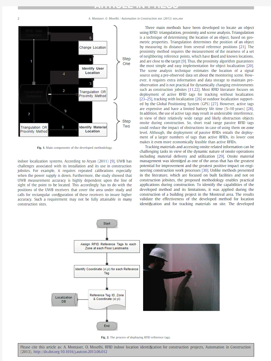
site and processing them using the triangulation or proximity method.In the second step of the algorithm,material location is identi ?ed making use of the mobile worker locations,which were identi ?ed in the ?rst step,and the captured signals from material tags;similarly processed as in the ?rst step using the triangulation or proximity meth-od.RFID reference tags are used as a reference point with a known loca-tion (landmark)within a prede ?ned zone.In this approach,passive RFID tags are distributed on the jobsite,and mobile worker(s)are equipped with RFID reader(s).In this study reinforced concrete columns,shear walls,curtain walls and wall edges were used as land-marks for the placement of reference tags.The known locations of the reference tags are used to estimate the location of the user,based on the RSSI received from these tags.
Locations of reference tags are identi ?ed with subscript (i),and the location of the workers (site personnel who carry the mobile RFID readers)is identi ?ed with subscript (j).It should be noted that materials are tagged in the fabricator's shop and hold the same ID as that in the 3D Building information Model (BIM)for the building.Prefabricated materials such as electromechanical equipment,curtain walls,precast concrete panels,etc.are tagged using encapsulated rugged tags attached via screws or epoxy adhesive according to the speci ?cation of each material.For packed materials such as wooden doors and frames,gypsum board panels,etc.,they are tagged using printed label RFID tags.One tag is for the pack itself to include informa-tion about the packed quantity and another printed label tag attached to each item inside the pack,if possible.For items such as bricks,it will not be bene ?cial or possible to tag each item.Loose materials such as concrete or excavated materials will not be tagged —other methods should be used to track this type.Subscript (k)is used for tracked material temporal location onsite and subscript (f)is used to represent the respective ?nal locations of the tracked materials.Fig.2illustrates the process of deploying RFID reference tags,which start with assigning RFID reference tags to each zone's landmarks.The coordinates (x i ,y i )of each reference tag (i)are then stored in the database knowing that all reference tags are deployed at the same height,which is 1.5m from ?oor level.This step is performed one time per ?oor and is used as input for location identi ?cation and tracking
purposes.
Fig.3.Path loss regression
model.
3
A.Montaser,O.Moselhi /Automation in Construction xxx (2013)xxx –xxx
The triangulation method requires a path loss model to convert RSSI to distance (D).Therefore,a set of experiments were conducted by the authors to develop a path loss model.The model was devel-oped using 6704data sets of laboratory experiments.Each data set consists of a number of signals captured at a speci ?c distance.Linear regression was carried out using the average of the captured signals'strength and the associated distance.Distance (r)was varied at an interval of 10cm.The developed relation is represented by Eq.(1)(See Fig.3).For more details about path loss,different regression models and the basis for deploying the linear model refer to Razavi et al.(2012)[19].r ?–0:1618RSSI –5:2863
e1T
Start
RFID Reader Current Location Lj Set j =1
Start Collecting Data Using Mobile
RFID Reader at t =to
Calculate Average (RSSI)i for each Reference Tag at Current Location Lj Convert Average (RSSI)i to Distance ri Move to Next Location
Set j =j +1
Date,Time &Location Lj (Xj,Yj)
End
RFID DB
Stop Collecting Data at t =to +Δt
D a t a C o l l e c t i o n
Path Loss Model r =f(RSSI)
Is All Zones Covered?Yes
No
Filter Reference Tags
Draw Circle at each Sensed Reference Tag
(xi,yi)with Radius ri
Identify the Intersection Area for the
Generated Circles
One Intersection Area Only?Calculate the Centroid for the Intersection
Area,Current Location (Xj,Yj)
Yes
Calculate ∑(r)for each Intersection Area
No
Select the intersection area with Minimum ∑(r)Trilateration Method
Append
Generate Report
Calculate Average (RSSI)i for each Reference Tag at Current Location Lj
Convert Average (RSSI)i to Weight Wi
Calculate Current Location (Xj,Yj)
W =f(RSSI)Xj =f(xi,W)Yi =f(yi,W)
Proximity Method
Fig.6.Flowchart for user location identi ?cation using the proximity method.
4 A.Montaser,O.Moselhi /Automation in Construction xxx (2013)xxx –xxx
3.Location of the mobile worker
The ?rst step in the developed algorithm is to identify the worker's stationary location using signals captured from reference tags as shown in Fig.4-a and the ?owchart shown in Fig.5.The worker L j at a given location (X j ,Y j )operates his RFID reader at a time t o and captures the signals received from the reference tags and materials at that loca-tion and time.This process is repeated at a set of time intervals;referred to here as Δt.In the ?eld experiments,Δt ranged from 15to 30s.The tag ID is used to distinguish RFID reference tags from material tags.A relational database was developed to ?lter these tags based on their respective IDs,and to ensure the use of signals,in the ?rst step of the developed algorithm,from related reference tags only.If a tag ID is for tracking materials,then it will be stored in the database for later processing in the second step.
The triangulation method determines the position of the mobile worker by measuring his distance from several reference tags.All readings collected from each reference tag are averaged and converted into an equivalent distance (r i ),using Eq.(1).When the localization algorithm identi ?es at least a set of three distances from different refer-ence tags,the algorithm generates circles;their respective centers are the known positions of the reference tags (x i ,y i ).The intersection of
Start
Filter Material Tags Data &
User Location Data Localizatrion
DB
Count #of Sensed Material Tags k
Let k =1to n
Set k =1
Does material k sensed in more than 2locations?
Location Could be Roughly Identified
Yes
Yes No
Is k =n?
Date,Time &
Material Location Lk
(Xk,Yk)
End
Move to Next Location
Set k =k +1
Yes
No
No A p p e n d
Calculate Average (RSSI)j for each Location
Lj Convert Average (RSSI)j to Distance rj Path Loss Model r =f(RSSI)
Draw Circle at each Location Lj (Xj,Yj)with
Radius rj
Identify the Intersection Area for the
Generated Circles
One Intersection Area Only?Calculate the Centroid for the Intersection
Area,Material Location (Xk,Yk)
Yes
Calculate ∑(r)for each Intersection Area
No
Select the intersection area with Minimum ∑(r)Trilateration Method
Generate Report
5
A.Montaser,O.Moselhi /Automation in Construction xxx (2013)xxx –xxx
these circles determines the expected signal source's location.In case the intersection is not in a point,but rather an area,the center of gravity (C.G.)of that area is used instead.Accordingly,the coordinates of the worker could be calculated (X j ,Y j ).It is worth noting that,in many cases,there is more than one intersection area.In such cases,the
following heuristic rule is applied.Rule:“if more than one area of inter-section exists,then the C.G.of the area formed by the circles having the least summation of their radii is used ”.This rule acts as a useful ?lter of noisy out-of zone-signals.The user moves to the next location in the same zone or another zone on site and the same procedure is repeated.The generated locations L j (X j ,Y j )will be stored in the database with their corresponding time for further utilization in the second step of the algorithm.
The proximity method can also be applied using the same process followed in the triangulation method.However,the proximity method uses Received Signal Strength Indicator (RSSI)as a weighting method to express how near the reader is to the reference tags.RSSI is a measurement of the power of the received radio signal.Therefore,the higher the RSSI number (or the less negative in some devices)is,the stronger the signal;indicating that the mobile worker is closer to that tag.The readings collected for each reference tag were averaged and converted into a related weight (W i ),which represents how much closer the reader is to that tag (See Fig.5).The coordinates of the worker (X j ,Y j )are calculated using Eq.(2).Fig.4-a,depicts the worker standing in a zone surrounded by three reference tags having coordinates (x 1,y 1),(x 2,y 2)and (x 3,y 3)and corresponding average signal strength
Material
Material
Tag
Has
Mobile RFID Reader
Read
1
M
1
1
Xf
Xf Name Name Arrival Date Arrival Date Price
Price Yf
Yf Project
No.
Project No.Quantity Quantity ID
ID Xk
Xk Yk
Yk ID
ID Date
Date Date
Date Time
From
Time From Yj
Yj Xj
Xj Deploy
Zones
Reference
Tag
ID
ID Floor No.
Floor No.ID
ID xi
xi 1
M
yi
yi Has
M
1
Located
Area
Area Entity
Attribute
Attribute Primary
Key
Primary Key Relationship
Time
To
Time To RFID
Signals
Capture
Date
Date ID
ID Time
Time RSSI
RSSI (RSSI)j
(RSSI)j Serial #
Serial #Period ID
Period ID M
1
N
Calculate Average (RSSI)j for each
Location Lj
Convert Average (RSSI)j to Weight Wj
Calculate Material Location (Xk,Yk)
W =f(RSSI)Xk =f(Xj,W)Yk =f(Yj,W)
Proximity Method
Proximity Method Fig.8.Flowchart for material location identi ?cation using the proximity method.
6 A.Montaser,O.Moselhi /Automation in Construction xxx (2013)xxx –xxx
(RSSI)1,(RSSI)2and (RSSI)3.This provides suf ?cient data to determine his location (X 1,Y 1)(Fig.6).xj ?
∑n
i ?1x i ?W i
∑n
i ?1W i
&Y j ?
∑n
i ?1y i ?W i
∑n
i ?1W i
e2T
4.Material location
After successful delivery of materials on site,it is distributed for use at different locations on site.While the mobile worker's location can be calculated in a straightforward manner as described earlier in step one of the algorithm,this is not the case for material location.The signals received from a material may indicate that it is near the user,but the directions of the received signals are unknown.The user moves to
another location to capture RFID signals and repeats step one of the algorithm to determine his new location.At this second location,the user again receives tagged material signals,and material location can be roughly estimated based on the region between these two locations.However,to increase the accuracy of calculating material locations L k ,the user moves to a third location and repeats the procedure performed at the previous two locations.After moving to the third location and receiving material signals from that location,the triangulation or prox-imity method is applied to identify material location L k based on the identi ?ed locations of the mobile worker.
The triangulation method determines the position of the material by measuring its distance from previously-identi ?ed locations of the worker.All collected material readings from each worker location are averaged and converted into an equivalent distance (r),using Eq.(1).When the localization algorithm identi ?es a set of at least
a) RFID mobile reader
b) RFID encapsulated tag
d) RFID tag printer
c) RFID label tag
Fig.11.RFID hardware used.
Table 1
Characteristics of test beds.Test bed #
Test bed 1Test bed 2Test bed 3Test bed 4Test bed 5Test bed 6Case study I
I
I
I
I
II
Date 01/12/2010
03/12/2010
08/12/2010
01/3/2011
14/04/2011
24/12/2011
Location
Jobsite (3rd ?oor)Jobsite (2nd ?oor)Jobsite (3rd ?oor)Jobsite (2nd ?oor)Jobsite (3rd ?oor)Lab environment Total number of prede ?ned locations 181818151545Total no.of samples 4184944517294385915Covered area (m 2)75.2475.2475.2410812061No.of deployed tags
2424242533252
Fig.10.(a)Case study I (b)Case study II.
7
A.Montaser,O.Moselhi /Automation in Construction xxx (2013)xxx –xxx
three distances from different locations of the mobile worker,the algorithm generates circles,the centers of which are the respective positions of the mobile worker (X j ,Y j ).Similarly,by applying the pro-cedure described earlier for worker's location,material locations are calculated.Fig.4-b shows the sequential steps of the procedure applied and Fig.7shows the ?owchart for the proposed method of material location identi ?cation using the triangulation method,which represents the second step in the proposed two-step
algorithm.
8 A.Montaser,O.Moselhi /Automation in Construction xxx (2013)xxx –xxx
As shown in Fig.4-b,the user moves to another location,for example L2(X2,Y2)and the RFID reader again receives signals from material(k). Also,when moving to a third location L3(X3,Y3),the reader keeps on receiving a signal form the same material(k).After receiving a signal from material(k)from at least three different locations,the location of material(k)can be calculated(X k,Y k).Fig.8shows a?owchart for the procedure used for material location identi?cation using the proximity method and using Eq.(3)to calculate the coordinates of each material being tracked.It should be noted that the three different locations should not be on the same line.Another reason for choosing three different locations instead of only two is that the material location would be on the line connecting the two locations and so would be automatically calculated as being closer to the location where the signal is stronger,which may give rise to higher errors.This process is repeated daily during the worker's walkthrough for data collection.At that point, material location could be identi?ed and tracked on a daily basis.Mate-rial temporal location,L k is compared to material?nal location L f captured from3D BIM in order to know whether the material is placed and/or installed in its?nal location or still in handling processes.
X k?
∑3j?1X j?W j
∑j?1W j
&Y k?
∑3j?1Y j?W j
∑j?1W j
e3T
5.Localization database
The developed RFID localization database is at the core of the pro-posed methodology.It contains relatively structured data relationships and schema designs.It is used for?ltering different types of tags and for data processing.Relational database management systems are better suited for the application at hand.The database consists of six entities or tables.The entities of the database are RFID signals,material,material tag,reference tag,mobile RFID reader and zone as shown in Fig.9.RFID
9 A.Montaser,O.Moselhi/Automation in Construction xxx(2013)xxx–xxx
signal entity is considered the main repository for the captured RFID data.It consists of six attributes and they are serial number,period ID, ID,data,time and RSSI.The serial number is automatically generated number to represent how many records have been captures by the RFID mobile reader.Period ID is used to?lter each of the data sets pertinent to worker's location.As such,the period ID increases incre-mentally as the worker moves from one location to another.A many to one relationship connects RFID signal and mobile RFID reader entity.
Mobile RFID entity represents the location of the mobile worker, which is calculated in near-real-time using the procedure described above and the quires and data stored for the RFID signal entity.This entity has?ve attributes:date,time from,time to,X j and Y j.A one to many relationship connects the mobile RFID entity and material tag entity.Material tag entity characterizes RFID tags attached to materials,and it has?ve attributes.The most valuable attributes in the material tag entity are X k and Y k.This is the material temporal location onsite,which is tracked daily with the date attribute.The “Material”and“Material Tag”entities have a one-to-many relationship. This relationship was created on the basis that one material or equip-ment is assigned one tag only.The relationship for“Zone”entity and “Reference Tag”entity was designed to be one-to-many.Material and Zone entities can either be extracted from project drawings or from the3D BIM of the project.
6.Experimental studies
For validating the proposed method and demonstrating the use of its components,experiments were conducted in two case studies. Case study I makes use of the construction of the Center for Structural and Functional Genomics at Concordia University(Fig.10-a).Other experiments were conducted in the Construction Automation Lab,at Concordia University(Fig.10-b).The RFID hardware components used in the two case studies are RFID mobile readers,RFID encapsu-lated tags,RFID label tags and a RFID label tag printer(Fig.11).The RFID hardware could collect data in dirty,harsh,and hazardous conditions.For example,the encapsulated RFID tag used,could work in temperatures ranging from?40°C to66°C and could be attached using screws,rivets,double-sided adhesive strips or a variety of other methods.Regarding its memory size,it has a capacity of512-bit-on-chip.In addition,the RFID mobile readers could work under similar harsh conditions such as temperatures ranging from?15°C to50°C, and are protected from dirt,dust,oil,other non-corrosive materials, and splashing water.The readers'connectivity could be Ethernet or Wi-Fi and can host applications written in Java,JavaScript,https://www.doczj.com/doc/108781387.html, or C#.Net.The read range for encapsulated tags is5m for and3m for label tags.The encapsulated RFID tag shown in Fig.11-b costs approxi-mately$5per tag.The passive RFID tags used in these experiments were printed RFID labels,which cost2cents each.The tag labels and the printer are shown in Fig.11(c&d),respectively[31].
Five test beds were setup at different time spans and different locations on site.Carrying out the tests at different time spans was required to prove that the proposed methodology is feasible during construction operations.Test bed6was setup in a lab environment. Table1shows the characteristics of each test bed,including the total number of data samples collected,date,location,test bed area and number of tags used in the test bed.Fig.12(a&c)shows the setup and images of test bed3where the rectangles refer to the loca-tions of attached reference tags.Fig.12-b shows a graphical display of the error in the calculated location of the mobile worker,which is the distance in meters between the estimated and actual locations. The triangles represent the worker's previously marked locations where he/she stands and starts capturing RFID signals.The circles and squares represent,respectively,the calculated location using the triangulation and proximity methods.A summary of statistical analysis for both the triangulation and proximity methods is
https://www.doczj.com/doc/108781387.html,parison between triangulation and proximity method(Case Study
I).
10 A.Montaser,O.Moselhi/Automation in Construction xxx(2013)xxx–xxx
developed methodology in identifying locations of the worker obtained from all test beds.Fig.14shows a comparison between the two methods.There are?ve sensed reference tags.Four of them related to the user zone and the?fth one is far away from the user https://www.doczj.com/doc/108781387.html,ing the triangulation method automatically selects the inter-section area of most circles and due to the?fth reading being away from that intersection,it will not be considered in calculations. However,the proximity method considers all readings and does not have this mechanism so the results are affected more by noise from reference tags that far from the user zone.
Fig.15shows a tracking material labeled C8utilizing user location numbers14,15and18.Similarly,a statistical analysis was performed for material location identi?cation and the results are summarized in Fig.16(a&b)for both methods(triangulation and proximity).The developed methodology yields100%accuracy for zone identi?cation of the worker and for the tracked material in all test beds.This proves its suitability for zone identi?cation on construction jobsites and/or operational built facilities.A Cumulative Distribution Function(CDF) was used to show the localization error and to measure the localiza-tion performance at a given con?dence level(see Fig.17).The CDF also indicates the error accumulation in material location due to the dependency on worker location.It is clear from Fig.17that in case of the triangulation method the error accumulated and increased rapidly.However,in case of the proximity method the error accumu-lation is steady.
The results indicate that the triangulation method is relatively more accurate than the proximity method for both user and material localiza-tion.However,the triangulation method suffers from drawbacks such as the dependency on path loss models(location-environment depen-dent models),which are not robust enough to represent the character-istics of radio waves and their interference in a dynamically changing construction environment.In addition,the computational time re-quired for identifying location using the triangulation method is much more than that for the proximity method due to the mathematical
11 A.Montaser,O.Moselhi/Automation in Construction xxx(2013)xxx–xxx
complexity of the triangulation method,which gives an advantage to proximity method in near-real-time localization.Further work is needed to address the impact of metal media proximity to RFID tags, optimum duration for data capturing,number of RFID tags employed, the distance between them and zone con?guration to provide guide-lines to the users of RFID technology for localization in building construction.
The proposed methodology is part of an ongoing research that integrates different automated data acquisition technologies for ef?-cient tracking and control of constriction operations through continu-ous monitoring of their respective tasks and activities[32,33].A project manager can analyze this data for different purposes such as safety and timing,taking corrective actions as needed.Therefore, the user identi?ed location in step one is crucial for this purpose and needs to be in near-real-time.After?nishing the?rst zone,the user moves to the next zone for data collection.These steps are repeated until all zones have been covered.The second step of the proposed algorithm will be used to track material locations and it does not need to be in real time.Materials such as electromechanical equipment can be directly identi?ed and tracked by attaching an RFID tag directly to the item and utilizing the same methodology.The second step of the algorithm will provide the project manager with
a daily layout of the materials per?oor.
7.Conclusion
This study presents a detailed methodology on utilizing a low cost location identi?cation and material tracking for indoor construction using a two-step algorithm.The proposed method utilizes UHF passive RFID technology for capturing spatial data in an indoor environment.In this study,the work-active area is divided into exclusive zones,and each zone is spatially covered with a number of passive RFID tags.The user and material locations are estimated using two different RFID methods(triangulation and proximity)based on RSSI signal measure-ment.A specially designed relational database was used to store and organize RFID captured signals.The methodology has been experimented on a construction facility in Montreal and a lab environ-ment.The results are presented and compared for5different test beds in different construction time intervals and1test bed in a lab environment.The results shows a mean error of1.0m and1.9m for user location identi?cation and material tracking using the triangula-tion method,respectively.The results shows a mean error of1.9m and2.6m for user location identi?cation and material tracking using the proximity method,respectively.The proposed methodology detects user location and material zones with100%accuracy.The results range RFIDs in location estimation and material tracking with a cost-effective manner for indoor construction jobsites.The developed method for location identi?cation and material tracking using RFID technology can be used to obtain information required for scalable and near-real-time decision-making,timely tracking of the project status and proactive safety monitoring.The study could be used in different types of buildings such as steel structure buildings.However, the tags should be encapsulated tags to reduce the impact of interfer-ence between radio waves and metals.The main limitations of the developed methodology are the need to generate a path-loss model for each type of tag used in case of using the triangulation method, the variability associated with deployment of tags,the uncontrolled in?uence of noisy signals and potential interference from equipment and/or vehicles located between tags and between tags and the mobile reader.
References
[1] C.Tzeng,Y.Chiang,C.Chiang,https://www.doczj.com/doc/108781387.html,i,Combination of radio frequency identi?cation
(RFID)and?eld veri?cation tests of interior decorating materials,Automation in Construction18(1)(2008)16–23.
[2] C.Caldas,D.Grau,C.Haas,Using global positioning systems to improve materials-
locating processes on industrial projects,Journal of Construction Engineering and Management(ASCE)132(7)(2006)741–749.
[3] A.Montaser,I.Bakry,A.Alshibani,O.Moselhi,Estimating productivity of earth-
moving operations using spatial technologies,Proceedings,Annual Conference—Canadian Society for Civil Engineering,3rd International/9th Construction Specialty Conference,Ottawa,Ontario,3,2011,pp.2318–2327.
[4]R.Navon,E.Goldschmidt,Monitoring labor inputs:automated-data collection
model and enabling technologies,Journal of Automation Construction12(2002) 185–199.
[5]J.Song,C.Haas,C.Caldas,E.Ergen,B.Akinci,Automating the task of tracking the
delivery and receipt of fabricated pipe spools in industrial projects,Journal of Automation in Construction15(2)(2006)166–177.
[6]R.Want,A.Hopper,V.Falcao,J.Gibbons,The active badge location system,ACM
Transactions on Information Systems40(1)(1992)91–102.
[7] F.V.Diggelen,Indoor GPS theory and implementation,Proceedings of the IEEE
Position Location and Navigation Symposium,IEEE,Piscataway,NJ,USA,2002, pp.240–247.
[8]J.Teizer,https://www.doczj.com/doc/108781387.html,o,M.Sofer,Rapid automated monitoring of construction site activities
using ultra-wideband,24th international Symposium on Automation&Robotics in Construction(ISARC),Madras,Oregon,USA,2007,pp.23–28.
[9] A.Aryan,Evaluation of ultra-wideband sensing technology for position location
in indoor construction environments.Masters'thesis,presented to University of Waterloo,Ontario,Canada,2011.
[10]Ubisense?Company,Product Fact Sheets,https://www.doczj.com/doc/108781387.html,/en/2012,
(accessed on28December).
[11]S.Woo,S.Jeong,E.Mok,L.Xia,C.Choi,M.Pyeon,J.Heo,Application of WiFi-Based
indoor positioning system for labor tracking at construction sites:a case study in Guangzhou MTR,Journal of Automation in Construction20(1)(2011)3–13. [12]J.Hightower,G.Borriello,Location systems for ubiquitous computing,Computer
34(8)(2001)57–66.
[13]K.Al Nuaimi,H.Kamel,A survey of indoor positioning systems and algorithms,
International Conference on Innovations in Information Technology proceedings (2011)185–190.
[14]N.Patwari,J.N.Ash,S.Kyperountas,A.O.Hero,R.L.Moses,N.S.Correal,Locating
the nodes:cooperative localization in wireless sensor networks,Signal Processing Magazine(IEEE)22(4)(2005)54–69.
[15]J.S.Choi,Accurate and Cost Ef?cient Object Localization Using Passive UHF RFID.
(PhD thesis)presented to the Faculty of the Graduate School of the University of Texas at Arlington,2011.
[16] E.Jaselskis,T.El-Misalami,Implementing radio frequency identi?cation in the
construction process,Journal of Construction Engineering and Management (ASCE)129(6)(2003)680–688.
[17]S.Chae,T.Yoshida,Application of RFID Technology to prevention of collision
accident with heavy equipment,Journal of Automation in Construction19(2010) 368–374.
[18] C.Legner,F.Thiesse,RFID-Based maintenance at Frankfurt airport,IEEE Pervasive
Computing5(1)(2006)34–39.
[19]S.N.Razavi, A.Montaser,O.Moselhi,RFID deployment protocols for indoor
construction,Journal of Construction Innovation:Information,Process,Management 12(2)(2012)239–258.
[20]N.Li,B.Becerik-Gerber,Performance-Based evaluation of RFID-Based indoor
location sensing solutions for the built environment,Advanced Engineering Informatics25(3)(2011)535–546.
[21]G.Gon?alo,S.Helena,A novel approach to indoor location systems using propa-
gation models in WSNs,International Journal on Advances in Networks and Services2(4)(2009)251–260.
[22]Q.Fu,G.Retscher,Active RFID trilateration and location?ngerprinting based on
Fig.17.Cumulative distribution function for estimated error for user and material location
identi?cation.
12 A.Montaser,O.Moselhi/Automation in Construction xxx(2013)xxx–xxx
[23]P.Goodrum,M.McLaren,A.Durfee,The application of active radio frequency
identi?cation technology for tool tracking on construction job sites,Journal of Automation in Construction15(3)(2006)291–302.
[24] E.Jaselskis,M.R.Anderson,C.T.Jahren,Y.Rodriguez,S.Njos,Radio frequency
identi?cation applications in construction industry,Journal of Construction Engineering and Management(ASCE)121(2)(1995)189–196.
[25] A.Montaser,O.Moselhi,RFID+for tracking earthmoving operations,Proceedings of
Construction Research Congress(CRC2012)ASCE,West Lafayette,IN,USA,2012, pp.1011–1020.
[26] E.Ergen,B.Akinci,B.East,J.Kirby,Tracking components and maintenance history
within a facility utilizing radio frequency identi?cation technology,Journal of Computing in Civil Engineering(ASCE)21(1)(2007)11–20.
[27] E.Ergen,B.Akinci,R.Sacks,Tracking and locating components in a precast
storage yard utilizing radio frequency identi?cation technology and GPS,Journal of Automation in Construction16(3)(2007)354–367.[28]K.Dziadak,B.Kumar,J.Sommerville,Model for the3D location of buried assets
based on RFID technology,Journal of Computing in Civil Engineering(ASCE)23 (2009)148–159.
[29]W.J.Rasdorf,M.J.Herbert,Automated identi?cation systems—focus on bar
coding,Journal of Computing in Civil Engineering(ASCE)4(3)(1990)279–296.
[30]M.C.Vorster,G.Lucko,Construction Technology Needs Assessment Update,
Research Report173–11,Construction Industry Institute(CII),Austin,TX,2002.
[31]Intermec Solutions.Inc.,RFID Products,http://www.intermec.ca/products/r?d/
index.aspx2012,(accessed December15,2012).
[32] A.Montaser,O.Moselhi,4D and Tablet PC for Progress Reporting,Proceedings of
International Symposium on Automation and Robotics in Construction(ISARC 2012),Eindhoven,Netherlands,2012.
[33] A.Montaser,O.Moselhi,RFID and BIM for Automated Progress Reporting,AACE
International Transactions,56th Annual Meeting,San Antonio,Texas,United States, 2012.
13
A.Montaser,O.Moselhi/Automation in Construction xxx(2013)xxx–xxx
RFID 保密设备及机要文件资产管理方案 项目背景及需求分析: 应用技术背景:近年来,RFID技术已经在社会众多领域开始应用,对改善人们的生活质量、提高企业经济效益、加强公共安全以及提高社会信息化水平产生了重要影响。根据预测,RFID标签技术将在未来2~5年逐渐开始大规模应用,到2008年RFID标签仅在全球供应链领域的市场需求将达到40亿美元。在未来的几年中,RFID技术将继续保持高速发展的势头。电子标签、读写器、系统集成软件、公共服务体系、标准化等方面都将取得新的进展。随着关键技术的不断进步,RFID产品的种类将越来越丰富,应用和衍生的增值服务也将越来越广泛。 RFID芯片设计与制造技术的发展趋势是芯片功耗更低,作用距离更远,读写速度与可靠性更高,成本不断降低。芯片技术将与应用系统整体解决方案紧密结合。 RFID标签封装技术将和印刷、造纸、包装等技术结合,导电油墨印制的低成本标签天线、低成本封装技术将促进RFID标签的大规模生产,并成为未来一段时间内决定产业发展速度的关键因素之一。 RFID读写器设计与制造的发展趋势是读写器将向多功能、多接口、多制式,并向模块化、小型化、便携式、嵌入式方向发展。同时,多读写器协调与组网技术将成为未来发展方向之一。 RFID技术与条码、生物识别等自动识别技术,以及与互联网、通信、传感网络等信息技术融合,构筑一个无所不在的网络环境。海量RFID信息处理、传
输和安全对RFID的系统集成和应用技术提出了新的挑战。RFID系统集成软件将向嵌入式、智能化、可重组方向发展,通过构建RFID公共服务体系,将使RFID 信息资源的组织、管理和利用更为深入和广泛。 本项目的用户背景:政府的机要单位,机要局是系统的建设和使用单位,其工作职责主要涉及: (一)承担密码领导小组的日常工作,负责党政系统的密码通信和密码管理;(二)负责密码电报的翻译、传输、批抄、传送、上呈下达; (三)负责上级明传电报、信息的接收、抄送; (四)负责市、区加密通信网络、党务内网和办公自动化规划、建设和管理;(五)负责政府各种通知、文件和信息的网上发布及下达; 这其中最主要的就是密码设备及文档,这套系统建设的意义就在于这些涉密资产的安全管理工作,系统建设的主要目的是运用RFID的技术运用手段对现有涉密级别比较高的文档和设备的安全进行管理。 需求分析及系统设计原则:由于此类客户对于资产及文件管理的安全系数要求极高,在系统的保密安全设计上必须考虑定义复杂的加密手段以及严谨的监控手段来达到较为合适的安保级别。 首先在RFID的标签选型上,选用带有逻辑加密功能的类型,其中几种比较合适的类型如下表所示: 逻辑加密电子标签
客户关系管理实习心得体会范文5篇 “客户经理与客户的关系不仅是业务关系,更是一种人的关系;客户经理的服务要有创意,要走在客户的前面。”下面是我收集推荐的客户关系管理实习心得,欢迎阅读参考。 精选客户关系管理实习心得(一) 通过两个星期的客户关系管理实习,让我明白了什么是CRM,让我更进一步了解到CRM对一个企业的重要性,最深的体会就是明白了实施CRM过程中一定要让客人明白自己的重要性,感觉到自己的意见是会被接纳了,自己也有发言的权利,让自己公司的服务能够远远超越客人的预期的,那么客人就会很满意,要用心去帮助客人,尝试站在客人的立场去看一件事,不要只想着一时的利益,因为假如你能够让客人满意的话,他们会变成你们的常客,就有一笔很可观的利益;但是,你的服务差的话,他们就不会再在你那里买东西,倒头来还不是亏了。从上海通用的实施过程可以看出,实施CRM是一个从硬件到软件,从营销理念到营销手段,从营销管理到生产管理的系统工程,而贯彻始终的是“以客户为中心”的经营思想。始于客户、终于客户,是CRM成功的关键。 有句话是这么说的“不学,不问没有学问;学习、不复习、不练习等于没出息”。经过这次的学习学到了很多东西,这些方法对以后的工作必然会有很大的帮助。为以后怎么跟客户打交道指明了方向。用“悟”的眼光去着眼未来的“大客户”,让客户不只是为了满足而只是付出的是价格,应该是让客户成为我们忠诚的客户,为的是价值。
在我的理解里面,我觉得这就是这次实习最大的收获,即是——知行合一。首先,知中有行,行中有知。二者互为表里,不可分离。知必然要表现为行,不行不能算真知。其次,以知为行,知决定行。知是行的主意,行是在的工夫;知是行之始,行是知之成。有了继续前进的动力,可以不断地知,不断地行。从书本里学,从老师处学,从同学处学,从自己处学——求知;在学习中行,在工作中行,在生活中行——行动、实践。 参考客户关系管理实习心得(二) 学习了《客户关系管理》课程,使我了解了许多关于客户方面的知识。就现代意义上说,你的客户就是你“服务的对象”。而这个对象有没有向你付钱并不重要,重要的是他从你处获得了服务,而你有某种义务保证这个服务的质量。而如今是供过于求的时代,作为“被追求方”的客户一般是比较挑剔的,只要有一个让他感觉不好,都可能导致企业的努力前功尽弃。所以做好客户关系管理是必不可少的。 crm是一种新经济背景下的管理理念,其核心是以客户满意度为目标的协同管理思想。crm同时也是一种基于以客户为中心思想的管理方式,围绕客户生命周期的发生、发展,采用精确营销的方法,通过协同工作,为分类的、不同价值客户提供满足个性化需要的产品和服务,从而达到留住客户、提高销售的目的。 通过学习了解到虽然客户关系管理这一现代企业经营管理模式给了我们很好的启示,虽然现在我国企业的经营者也十分清楚客户是重要的,客户是企业盈利的主体,但遗憾的是,我国很多企业的经营者却并不是很清楚企业该如何赢得客户,如何识别客户,如何管理客户,如何用crm去打造企业的核心竞争力。这些企业的经营理念、业务流程、组织结构、企业文化都还不能适应这样的管理模
R F I D固定资产管理系统 解决方案 Company Document number:WUUT-WUUY-WBBGB-BWYTT-1982GT
RFID 固定资产管理系统解决方案 一、系统目标 当前的资产管理借助于传统的人工管理方法和手段,数据的采集和录入一直都是手工操 作,效率低下、差错率高,且资产实物信息与管理系统信息无法实时同步。RFID技术作为 物理世界与现有 IT系统的桥梁,可将资产日常管理活动与资产管理系统有效的整合在一起, 从而达到实物信息与系统信息的实时同步一致。 通过 RFID这项新技术实现远程、动态、实时的设备资产数据采集,替换传统资产管理 方式的前台人工数据采集,更好的与后台计算机数据库结合,实现对日常管理中的资产信息 进行实时监控、记录和自动更新,同时采集人员信息,真正实现“帐、卡、物、人”相符; 并且按照国内固定资产折旧的实际情况和惯例,对固定资产自动进行计提折旧。将原来分散 的资产管理信息集中起来,组合成为一个整体的资产管理信息平台,从而避免因人为因素造 成的信息失真引起管理效能的下降。为单位领导、网络规划投资与设计等部门提供更准确、 实时的网络资产实物信息,提高资产使用效率,有效降低和控制日常管理和生产成本,对涉 密的资产进行严格监控并防盗,从而创造良好的社会及经济效益。 二、系统架构 系统简介 资产管理示意图如图 2,资产管理包括资产的新增、调拨、闲置、报废、维修和盘点等 操作,它包含了设备从购置、投入使用到报废的全过程。设备投入使用前加装电子标签,标 签内写入资产的信息,每次进行资产管理操作时,读写器都会读到资产上的电子标签并将信 息发送到资产管理系统服务器进行处理,从而实现资产的跟踪管理。
RFID智能仓库管理系统方案1 基于RFID技术的智能仓库管理系统解决方案 一、系统背景 仓储管理在物流管理中占据着核心的地位。传统的仓储业是以收保管费为商业模式的,希望自己的仓库总是满满的,这种模式与物流的宗旨背道而驰。现代物流以整合流程、协调上下游为己任,静态库存越少越好,其商业模式也建立在物流总成本的考核之上。由于这两类仓储管理在商业模式上有着本质区别,但是在具体操作上如入库、出库、分拣、理货等又很难区别,所以在分析研究必须注意它们的异同之处,这些异同也会体现在信息系统的结构上。 随着制造环境的改变,产品周期越来越短,多样少量的生产方式,对库存限制的要求越来越高,因而必须建立及执行供应链管理系统,借助电脑化、信息化将供应商、制造商、客户三者紧密联合,共担库存风险。仓储管理可以简单概括为8个关键管理模式:追-收-查-储-拣-发-盘-退。 库存的最优控制部分是确定仓库的商业模式的,即要(根据上一层设计的要求)确定本仓库的管理目标和管理模式,如果是供应链上的一个执行环节,是成本中心,多以服务质量、运营成本为控制目标,追求合理库存甚至零库存。因此精确了解仓库的物品信息对系统来说至关重要,所以我们提出要解决精确的仓储管理。 仓储管理及精确定位在企业的整个管理流程中起着非常重
要的作用,如果不能保证及时准确的进货、库存控制和发货,将会给企业带来巨大损失,这不 仅表现为企业各项管理费用的增加,而且会导致客户服务质量难以得到保证,最终影响企业的市场竞争力。所以我们提出了全新基于RFID射频识别技术的仓库系统方案来解决精确仓储管理问题。 使用RFID仓储物流管理系统,对仓储各环节实施全过程控制管理,并可对货物进行货位、批次、保质期、配送等实现RFID 电子标签管理,对整个收货、发货、补货等各个环节的规范化作业,还可以根据客户的需求制作多种合理的统计报表。RFID技术引入仓储物流管理,去掉了手工书写输入的步骤,解决库房信息陈旧滞后的弊病。RFID技术与信息技术的结合帮助商业企业合理有效地利用仓库空间,以快速、准确、低成本的方式为客户提供最好的服务。 二、系统优势 1.读取方便快捷:数据的读取无需光源,甚至可以透过外包装来进行。有效识别距离更长,采用自带电池的主动标签时,有效识别距离可达到30米以上; 2.识别速度快:标签一进入磁场,阅读器就可以即时读取其中的信息,而且能够同时处理多个标签,实现批量识别; 3.穿透性和无屏碍阅读:条形码扫描机必须在近距离而且没有物体阻挡的情况下,才可以辨读条形码。RFID能够穿透纸张、木材和塑料等非金属和非透明的材质,进行穿透性通信,不需要
RFID 固定资产管理系统解决方案 一、系统目标 当前的资产管理借助于传统的人工管理方法和手段,数据的采集和录入一直都是手工操作,效率低下、差错率高,且资产实物信息与管理系统信息无法实时同步。RFID技术作为物理世界与现有IT系统的桥梁,可将资产日常管理活动与资产管理系统有效的整合在一起,从而达到实物信息与系统信息的实时同步一致。 通过RFID这项新技术实现远程、动态、实时的设备资产数据采集,替换传统资产管理方式的前台人工数据采集,更好的与后台计算机数据库结合,实现对日常管理中的资产信息进行实时监控、记录和自动更新,同时采集人员信息,真正实现“帐、卡、物、人”相符;并且按照国内固定资产折旧的实际情况和惯例,对固定资产自动进行计提折旧。将原来分散的资产管理信息集中起来,组合成为一个整体的资产管理信息平台,从而避免因人为因素造成的信息失真引起管理效能的下降。为单位领导、网络规划投资与设计等部门提供更准确、实时的网络资产实物信息,提高资产使用效率,有效降低和控制日常管理和生产成本,对涉密的资产进行严格监控并防盗,从而创造良好的社会及经济效益。 二、系统架构 2.1 系统简介 资产管理示意图如图2,资产管理包括资产的新增、调拨、闲置、报废、维修和盘点等操作,它包含了设备从购置、投入使用到报废的全过程。设备投入使用前加装电子标签,标签内写入资产的信息,每次进行资产管理操作时,读写器都会读到资产上的电子标签并将信息发送到资产管理系统服务器进行处理,从而实现资产的跟踪管理。
图2、资产管理示意图 2.2 系统架构 RFID应用解决方案系统架构如图3,包含对象层、采集层和应用层;对象层主要是贴标的受控资产、文件和人员;采集层主要包括固定式RFID数据采集系统和手持式RFID数据采集系统,固定式RFID数据采集系统安装在各监控出入口,识别的数据通过局域网与应用层进行通讯,手持式RFID数据采集系统可用来对资产、文件或人员进行稽查和盘点等,通过WIFI、GPRS或USB与应用层进行通讯;应用层通过与采集层的数据通讯和数据处理实现各种管理功能。
实习心得 CRM是一个获取、保持和增加可获利客户的方法和过程,也是企业利用IT技术和互联网技术实现对客户的整合营销,是以客户为核心的企业营销的技术实现和管理的实现。CRM是一种技术手段,它的根本目的是通过不断改善客户关系、互动方式、资源调配、业务流程和自动化程度等,达到降低运营成本、提高企业销售收入、客户满意度和员工生产力。企业以追求最大赢利为最终目的,进行好客户关系管理是达到上述目的的手段,从这角度可以不加掩饰的说,CRM的应用是立足企业利益的,同时方便了客户,让客户满意。 刚开始接触这套系统时就是感觉东西太多、很乱,都不知道哪一部分是用来干什么的,数据又是从哪里输入,又怎么进行统计处理。后来经过摸索,才有数据出来,才实现了这套系统的一小部分的功能。经过这次软件实习,我才知道,管理是那么复杂的一套过程,而且拥有管理的知识还是不够的,还需要会使用系统,只有会用,才能发挥系统的作用,提高管理的效率,促使企业管理好经营好。所以还需要去学更多专业的知识,这样才能让我们在以后的工作中有东西可以用,而不是空壳子!所有数据都是我们小组成员随机编写,然后根据我们所输入的数据进行模拟实验,在实践过程中得到有关此软件的更多知识的使用数据,对CRM系统有了更深入的掌握,同时也发现了我们这类“使用者”的问题: 1、业务流程的不熟悉,应当加强对相关业务认知了解。 2、软件操作的生疏,应当将此类管理软件继续使用,在将来能够达到举一反三的效果。 3、模拟数据的不合理性,应当深入了解管理软件所涉及的行业的基本情况。 4、对于软件的增值功能没有完全发掘出来,今后加强此方面的研究的探索。 5、我们自己的能力还是不强,应用能力,管理能力,实践能力,适应能力。 现在,我们正处在一个一切都随手可及的E时代,客户可以极方便的获取信息,并且更多地参与到商业过程中。这表明,现在我们已经进入客户导向时代,深入了解客户需求,及时将客户意见反馈到产品、服务设计中,为客户提供更加个性化、深入化得服务,将成为企业成功的关键。 21世纪,对于任何企业而言,有两个方面最为重要,第一是企业品牌,第二就是顾客的满意度,但顾客的满意和忠诚不是通过简单的削价可以换来,也不是通过折扣、积分等暂时的经济利益可以换来的,要靠顾客关系管理(CRM)系统,从与顾客的交流互动中更好的了解顾客需求来实现。忠诚、持久而稳定的顾客群成为企业最宝贵的资源。 此外,CRM系统的实施需要具有扎实业务操作经验的人才;敏捷、富于创造性,最少受行业束缚的人才;来自IT并熟悉本行业业务的人才;来自本行业并熟悉技术应用的人才;具有新环境销售潜力的人才;具有熟练的数学和统计才能的人才;在与客户交流环境中能熟练应用信息的人才。这也对我们21世纪的大学生提出了严峻的挑战。面对时代对我们提出的新要求,我感到了自己肩上担子的沉重,业明白了自己应该承担的责任和需要履行的义务。但我坚定地相信:我们完全有这个能力来完成这一历史使命,并且会完成得很出色! 另外,我觉得无论在什么情况下团队精神都是很重要的。我们小组成员在这次实习中,每个人都积极参与到每个环节中去,积极地思考,积极地解决遇到的每一个问题。希望我们在以后的学习、工作和生活中不断地学习、思考,充实自己,取得更大的成功。
三、系统特点 RFID的无线即时远距离读取方式、大容量和高速数据处理能力以及高度的自动化,使它具备不可替代的技术优势; 货物,货车等数据可实时于因特网上查对、管理; 虚拟库存跟踪; 系统易于安装维护; 数据获取高效,准确; 系统实时跟踪人,货物,托盘,叉车,货车等所有物流环节; 物流的所有环节和流程都被实时监控。 四、系统组成 1、阅读器:本系统采用UHF915MHz阅读器,分别为固定安装阅读器和手持式阅读器,阅读器通过天线感应标签,并读取标签内的数据信息。固定安装阅读器对标签读取的距离可以达到八米以内,而手持式阅读器的读取距离为1米左右。(见下图)
2、标签:标签有各种款式,如卡片式,信用卡大小,安装在货车、集装箱上,安装在托盘,货物,包裹上,标签有各种封装形式,可针对性地选择。每个标签拥有一个全球唯一的ID 号码,在实际的应用中,它被赋予被安装物件、货物的信息以做识别、读取,并可回收利用。标签可以十分方便地附着安装在待识别物体上。(下图) 3、管理软件:阅读器在获取大量标签的数据后可以直接接入计算机/掌上电脑/笔记本电脑的端口,即时自动输入系统数据库,由管理软件进行管理。管理软件为网络版,这意味着在全球的任何一台因特网电脑上,管理者或者用户都可以实时对货物进行查验、管理,了解货车的所在位置等。信息上传到一个普通的Internet平台,这样货物端到端实时运动的可视化场景就能获得。 五、系统实现 5.工作人员或者叉车司机可以通过手持读卡器查在仓库内的货物进行信息收集,查找,快速便捷,大大提高了仓储盘点,查货的效率和准确率。(见附图E)在汽车的挡风玻璃上安装标签,在集装箱上安装标签,在大宗货物的容器和包装上安装标签。标签放在汽车挡风玻璃上,它可利用内部写入的唯一识别码或直接写入车辆信息(车牌号、所载货物)等来标识汽车及其装载货物。标签将内存数据调制反射给天线的微波信号上。货车经过各站点,由安置在各站点的阅读器识别经过的货车,记下货车到达该点的时间,货车内托盘及货物的信息,自动连接数据库比对,并上传因特网系统,达到实时跟踪的效果。最后,通过计算机局域网络,送至有关人员的计算机终端,实现了管理者不出门就能掌握货场车辆运用情况,控制车辆及其装载货物进出的目的。而当运载集装箱和大宗货物的交通工具经过运输网点RFID阅读器的感应范围时,集装箱和货物将被自动识别,并传输给计算机。(见附图)
客户关系管理实习心得体会范文5篇 精选客户关系管理实习心得 (一) 通过两个星期的客户关系管理实习,让我明白了什么是CRM,让我更进一步了解到CRM对一个企业的重要性,最深的体会就是明白了实施CRM过程中一定要让客人明白自己的重要性,感觉到自己的意见是会被接纳了,自己也有发言的权利,让自己公司的服务能够远远超越客人的预期的,那么客人就会很满意,要用心去帮助客人,尝试站在客人的立场去看一件事,不要只想着一时的利益,因为假如你能够让客人满意的话,他们会变成你们的常客,就有一笔很可观的利益;但是,你的服务差的话,他们就不会再在你那里买东西,倒头来还不是亏了。从上海通用的实施过程可以看出,实施CRM是一个从硬件到软件,从营销理念到营销手段,从营销管理到生产管理的系统工程,而贯彻始终的是“以客户为中心”的经营思想。始于客户、终于客户,是CRM成功的关键。 有句话是这么说的“不学,不问没有学问;学习、不复习、不练习等于没出息”。经过这次的学习学到了很多东西,这些方法对以后的工作必然会有很大的帮助。为以后怎么跟
客户打交道指明了方向。用“悟”的眼光去着眼未来的“大客户”,让客户不只是为了满足而只是付出的是价格,应该是让客户成为我们忠诚的客户,为的是价值。 在我的理解里面,我觉得这就是这次实习最大的收获,即是——知行合一。首先,知中有行,行中有知。二者互为表里,不可分离。知必然要表现为行,不行不能算真知。其次,以知为行,知决定行。知是行的主意,行是在的工夫;知是行之始,行是知之成。有了继续前进的动力,可以不断地知,不断地行。从书本里学,从老师处学,从同学处学,从自己处学——求知;在学习中行,在工作中行,在生活中行——行动、实践。 参考客户关系管理实习心得 (二) 学习了《客户关系管理》课程,使我了解了许多关于客户方面的知识。就现代意义上说,你的客户就是你“服务的对象”。而这个对象有没有向你付钱并不重要,重要的是他从你处获得了服务,而你有某种义务保证这个服务的质量。而如今是供过于求的时代,作为“被追求方”的客户一般是比较挑剔的,只要有一个让他感觉不好,都可能导致企业的努力前功尽弃。所以做好客户关系管理是必不可少的。
软件主要功能: RFID仓库管理系统软件平台,主要将RFID技术特性与仓库管理的流程结合,在软 件上实现更科学、可视化的管理。下面针对软件上其几个重要的功能进行介绍: 1、入库管理 在仓库的门口部署RFID固定式读写器,同时根据现场环境进行射频规划,比如可以 安装上下左右四个天线,保证RFID电子标签不被漏读。接到入库单后,按照一定的规则 将产品进行入库,当RFID电子标签(超高频)进入RFID固定式读写器的电磁波范围内会 主动激活,然后RFID电子标签与RFID固定式读写器进行通信,当采集RFID标签完成后,会与订单进行比对,核对货物数量及型号是否正确,如有错漏进行人工处理,最后将 货物运送到指定的位置,按照规则进行摆放。RFID在仓库管理应用中最主要的优势非接 触式远距离识别,且能够批量读取,提高效率与准确性。 2、出库管理 根据提货的计划,出库的货物进行分拣处理,并进行出库管理。如果出库数量较多时,将货物呈批推到仓库门口,利用固定式读写器与标签通信,对出库的货物的RFID电子标 签采集,检查是否与计划对应,如有错误,尽快的人工处理。对于少量的货物,可以使用RFID手持式终端进行RFID电子标签的信息采集(手持扫描枪或RFID平板电脑),出现 错误时,会发出警报,工作人员应该及时的处理,最后把数据发送到管理中心更新数据库 完成出库。
3、盘点管理 按照仓库管理的要求,进行定期不定期的盘点。传统的盘点,耗时耗力,且容易出错。而这一切RFID把这些问题解决了,当有了盘点计划的时候,利用RFID手持式的终端进 行货物盘点扫描,盘点服装的信息,可以通过无线网络传入后台数据库,并与数据库中的 信息进行比对,生成差异信息实时的显示在RFID手持终端上,供给盘点工作人员核查。 在盘点完成后,盘点的信息与后台的数据库信息进行核对,盘点完成。在盘点的过程中, 系统通过RFID非接触式读取(通常可以在1~2米范围内)非常快速方便地读取服装货物信息,与传统的模式相比,会提高很多效率和盘点的准确性。
目录 1. 前言 (3) 2. 系统简述 (4) 2.1. 系统特点 (4) 2.2. 系统优势 (5) 3. 系统架构 (6) 3.1. 总体架构 (6) 3.2. RFID系统组件 (7) 3.2.1. 手持机 (7) 3.2.2. 电子标签 (7) 3.2.3. 发卡机 (7) 3.2.4. 基于RFID技术的资产管理系统 (7) 4. 系统功能 (8) 4.1. 资产日常管理功能 (8) 4.2. 资产折旧 (8) 4.3. 固定资产月报 (8) 4.4. 固定资产综合查询 (9) 4.5. 盘点功能 (9) 4.6. 系统维护功能 (10) 4.7. 安全管理功能 (10) 5. 系统流程.................................................................................................................................... 11 5.1. 资产新增操作 (11) 5.2. 资产调拨操作 (12) 5.3. 资产维修操作 (13) 5.4. 资产报废操作 (14) 5.5. 资产盘点操作 (14) 6. 系统效益.................................................................................................................................... 15 7. 系统设备介绍............................................................................................................................ 16 7.1. 手持读写器 (16) 7.2. 桌面式超高频读写器 (17) 7.3. 电子标签 (17) 杭州紫钺科技有限公司Impinj增值分销商 3 1.前言
RFID智能仓库管理解决方案 背景: 江山天安是一件专业的非标钢质门生产的大型企业,以非标钢质门的加工生产为主。企业生产基本是按单生产,基本是一单一门。仓库的一般情况下的出入库数量在1000套门左右,高峰期可达到2000左右。同时,在库的成品门一般保持在10000套左右。仓库面积234X30M,在这样大的库房及库容量的库房中执行出入库、盘点等业务是相对比较复杂的。人工操作的稍有不慎,就可能会造成出入库差错、帐物不符、寻找困难等情况出现,给企业的生产经营带来诸多困难。 随着企业的发展与企业生存环境的变化,对我们的管理提出了更高的要求。RFID技术是一种无线射频识别技术。具有非可视识读、远距离识读、多目标识读、环境适应性强等诸多特点,相对于生产、仓储和运输等环节对设备的要求而言具有比较高的可靠性。 一.系统结构 企业目前已经部署ERP系统,RFID系统的数据最终需要汇集到现有的ERP系统处理。
ERP 系统 固定式设备固定式设备 手持设备 W i f i 手持设备 1. 包装入库 包装入库人员在对成品门打包包装的同时将RFID 标签以合适方式固定在门上,同时采用手持机读取标签数据,并在手持终端软件系统中填写相关信息。 在仓库的各个货位上部署标签,标识货位信息,并在软件系统中建立基于RFID 标签标识的仓库货位信息表。包装入库人员在将门安放进制定货位时,先识读当前货位标签,确定(或选择)货位,并与即将放入的门绑定。这样就保障了成品门进入准确的货位。 手持终端设备通过部署的WIFI 网络实时连接到企业ERP 系统,若网络系统存在故障,手持设备可以保存数据,在网络恢复是上载,或手动上载入库数据信息。 入库完成后系统可以自动产生入库单,由仓库管理人员
Rfid固定资产管理解决方案 关键词:rfid,资产管理,RFID技术,电子标签,紫钺, 简介 杭州紫钺科技有限公司专注于射频识别领域,为客户提供有价值的射频识别解决方案。紫钺科技作为Impinj中国大陆首家增值产品分销商。基于全球领先的Impinj产品与技术为客户提供固定式读写器、芯片、天线、各种封装形式的电子标签等产品与服务,提供物流仓储、城市交通、高校、生产线检测、食品安全与追溯等领域的关键解决方案服务。 1、系统简述 资产管理包括资产的新增、调拨、闲置、报废、维修和盘点等操作,固定资产管理是企业管理中的一个重要组成部分,固定资产具有价值高,使用周期长、管理难度大等特点。针对这些问题,本系统运用RFID 技术,从而实现固定资产的信息化管理。 1.1、系统特点 1)系统功能更实用 固定资产管理系统包括资产增加、变更、报废、毁损、折旧、借出、归还、分配使用部门、使用部门变更、管理人员设定、资产在部门间调换、各种报表打印、组合查询等。对于每一件固定资产都可以查询出该资产从购入、入帐、投入使用、使用部门、折旧情况、以至退出使用的全部信息都可以有详尽地记录。动态查询功能可以保证管理人
员在第一时间掌握全面的信息资料,资产成批折旧可以减少大量重复劳动并保证了数据的准确性。自动报表编制打印迅速准确,可以节约大量手工编制报表的时间。固定资产管理系统将原来分散的管理信息集中起来,组合成为一个具有整体功能的管理平台。 2)先进的管理方式 每一件新购入资产的相关数据输入计算机以后,都会根据相应软件将信息写入RFID标签内,RFID标签的内容可由用户自己设定,其中包括固定资产名称、购入日期、保管(使用部门)等内容。将不通种类的RFID标签贴在固定资产实物上,既明显地区分固定资产的使用部门,又给盘点带来极大的方便,盘点人员不必通过记录资产编码、核对帐本的方式进行盘点,只须通过手持读写器对固定资产上的RFID 标签识读,从而达到资产信息的比对。 3)高效的数据传输 固定资产管理系统不但能够在本机查询固定资产情况,还可通过企业内部网(Intranet)以及互联网(Internet),实现双向传输,使各种信息数据在同一时刻被其他用户共享。 4)独特的权限管理 在固定资产管理系统中充分地考虑到每一个操作员的职责不同,为每一个操作员制定了相应地操作权限,通过用户的身份和密码识别,保证不同操作员只能在其职责范围内进行有限的操作。这样既保证了制度的固定性,又能具有一定的灵活性以加强适应能力。 5)友好的用户界面、简便易学
. 客户关系管理实验报告 班级:电子商务1301 班 学号: 02132012 姓名:杨烨 文档资料Word
. 目录 实验一了解CRM系 统 (1) 1. 1登 陆 (1) 1.2系统选项和个性化管理 ................................................. 1 1.3自定义设 置 (1) 1.4用户管 理 (1) 1.5权限设 置 (2) 实验二客户管 理 (3) 2.1新增、编辑和删除客户 ................................................. 3 2.2渠道管 理 (8) 2.3供应商管 理 (8) 2.4 检索中 心 (10) 2.5 机会-项目-后期维护管理器 (11) 2.6 服务管 理 (12) 2.7 来电处 理 (12) 实验三进销存管 理 (13) 3.1 商品管 理 (13) 3.2采购管 理 (14) 3.3 付款管 理 (14) 3.4 采购退 货 (15) 3.5 销售管
3.6 收款管 理 (16) 3.7 发货管 理 (16) 3.8 销售退 货 (17) 实验四营销中 心 (17) 4.1 报价管 理 (17) 4.2合同管 理 (18) 4.3 费用管 理 (19) 4.4 绩效考 核 (19) 4.5 市场活 动 (19) 4.6 成本分 析 (20) 4.7 统计分 析 (20) 实验五我的办公 室 (22) 5.1 工作安 排 (22) 5.2 日程安 排 (23) 5.3 文件中 心 (24) 5.4 通讯 录 (24) 5.5 知识 库 (25) 实验六通讯中 心 (26) 6.1 公告 栏 (26) 6.2 短信管 理 (26) 文档资料Word . 6.3 邮件管
RFID智能仓库管理 应用方案 2017年2月
目录 1 项目背景 (1) 2 方案简介 (2) 2.1 应用框架流程图 (2) 2.2 软件系统简介 (3) 2.3 硬件简介 (4) 2.4 工作流程简介 (6) 3 系统优势 (7) 4 系统实施步骤 (10)
1 项目背景 当前物流环节存在的费用高、效率低的实际情况,依时利通过调研拜访第三方物流仓库经营企业、工厂自用仓库企业等仓库一线用户,发现传统仓库管理存在如下问题: 入库通知:货物都要入库了,入库单还没有送下来,不能立即投入工作。 入库完成:送货车辆都走了好久了,一查,货物还是未入库状态。 入库:货物已经搬入仓库摆放整齐了,入库完成了吗?没有,还要记录货物存放信息,但面对一批货物要放入几十上百个货架库位,普通的仓库管理系 统难以快速维护。 单据:五花八门的送货单、出库单、载货清单,没有一个标准,换个新人,先培训1个月再说。 业务:业务兴隆是好事情,可管理跟不上,只能看着客户流失。 理货:发现货物放置不合适,想调整下位置,担心造成货物存放位置不正确。 理货:一个理货员,每天理货的库位位置很多,能记清楚每个位置的货物存放么? 理货:仓库面积大,库位数量多,理货怎么安排?加人也不能有效的解决问题。 盘点:一盘就是几天,效率真低,效率低还算了,老出错,咋整? 面对当前物流企业市场激烈的行业竞争和社会对物流费用、物流效率提升的迫切要求,依时利RFID智能仓库系统从一开始就着手于解决物流关键环节:仓库内部的物流效率与管理效率提升,通过摆放仓库企业一线用户,调查其业务状况,管理状况,软件系统状况,我们分析出仓库管理存在以上问题的关键: 1、仓储管理数据提交不实时,导致数据与实物不符合。 2、仓库管理不够科学,没有形成标准化。 3、仓库现有机械设备没有处理自动处理业务的设备基础. 为解决这两个核心问题,依时利通过与仓库企业合作,历时2年,开发出了一套可以解决实际仓库管理难题、明显提升管理效率的软硬件集成系统。
. 企业资产管理解决方案 1.背景 资产设备是每个企业单位正常生产运营的重要物质基础,然而随着企业规模的不 断扩大,资产数目和种类的逐渐增加,其管理和调配成为日益繁琐的工作。如何才能高效的管理,提高设备利用率,减少闲置资产,节约资金,成了企业关注的焦点。 目前传统的方式主要是通过人工,数据的采集和录入都是手工操作,效率低下、差错率高,资产实物信息与系统信息无法实时同步导致资产缺乏跟踪管理,比如安装、移动、调拨、维修、报废没有历史记录,账目与实物不符等。诸多的问题 使得一种新型的资产管理模式显得十分必要。因此RFID技术在资产管理方面应运而生。 2.RFID应用前景分析 RFID(Radio Frequency Identification,射频识别技术),作为一种新兴的非接触式的自动识别技术,因其操作便捷高效,无需人工干预,可在各种恶劣环境下,通过射频信号自动识别目标并获取相关数据. 亦可识别高速运动中的物体,或同时识别多个标签,已逐渐成为21世纪全球自动识别技术发展的主要方向。 与传统的前台人工数据采集不同,RFID技术通过远程、动态、实时的设备资产 数据采集,更好的与后台计算机数据库结合,对日常管理中的资产新增、调拨和盘点等信息进行实时监控、记录并自动更新,实现了实物与系统信息的实时同步。同时采集人员信息,避免因人为因素造成的信息失真引起的管理效能下降。资料word . 实现了资产的日常管理活动与其系统有效整合,高效快捷,大大降低运作成本,提高资产利用率。 RFID资产管理特点 每件固定资产拥有各自电子身份证,方便登记与查找
快速识别、盘点与统计实物,可远距离,多目标操作。 帐、卡、物信息匹配清晰准确 轻松地知道每件物品的位置信息 资产跟踪管理活动完整,历史记录具体可查。具体管理操作记录及时可行。如安装、移动、调拨、维修、报废、保修、报废销账等。 目前,我国企业采用RFID技术进行资产管理的仍不多。尽管RFID技术已在仓储、物流、图书管理等很多领域得到广泛应用,但仍有一些因素制约着RFID技术的快速发展和大规模应用。 (一)标准问题。标准化是推动产品广泛获得市场接受的必要措施,但射频识别 读/写机与标签技术仍未统一,因此无法一体适用。目前各产品制造商、自动识别实验室与国际标准组织正在致力于制定射频识别技术的标准,以求所有的标签能够被任何读/写机兼容。 (二)成本问题。RFID系统建立成本分为初建费用和运行费用。初建费用包括:RFID接收读取器、电子标签、管理用微机等设备费用和搭建网络的费用。至于网络,企业可利用现有网络。RFID系统的设备功率都很小,很少需要维护, 其运行费用比较低。项目需要进行设备采购、系统搭建、软件编制和系统授权等方面的投资,此外还需支付项目组成员的工资、咨询公司的咨询服务费和集成 公司的项目集成费。因此,客观全面地评价RFID技术投资回报率是一个比较复资料word . 杂的课题,随着技术的突破、成本的降低将会逐步实现。 (三)技术完善问题。虽然单项技术已经趋于成熟,但RFID电子标签总体上产 品技术还不够成熟,还存在较高的差错率。识别距离方面,采用高频频段的 RFID标签的有效识别距离仅为1米,采用超高频频段的识别距离可以达到3米~6米,还不能达到理论上的识别距离(10米)。此外,射频识别标签与读写器具有方向性,且射频识别信号容易被物体所阻断,环境中的建筑结构尤其是金属结构的排列、数量会对RFID系统的安装和识别效果产生影响,这些都是RFID 技术未来发展的重大挑战。 (四)集成应用问题。当前企业的众多管理系统在设计时大多以条形码和磁条技
昊天科技RFID仓储管理系统项目经验分享1标识方式 1.1货位标识方式 标识方式每个货位一个电子标签。 标识类型背胶粘贴。 标识位置1)高位货架的货位,将电子标签粘贴在托盘上。货架 和托盘上原有的一维条形码仍然保留,便于仓储管理员核对。 2)自动化立体库的货位,将电子标签粘贴在周转箱上。 3)阁楼式货架的货位,将电子标签粘贴在货箱上。 4)地铺和悬臂式货架的货位,将电子标签粘贴在原有 的一维条形码旁边。 如果是高位货架上的货位,将电子标签粘贴在托盘上,作为货位的唯一标识,如下图所示:
如果是周转箱或货箱,将电子标签粘贴在一侧,如下图所示: 1.1.1 叉车标识方式 在叉车的两侧处,粘贴电子标签各一枚,如下图所示:
1.1.2 备件标识方式 不可独立标识的备件,如弹簧垫圈、钢绞线等,需与供应商合同约定,提供适合张贴电子标签的物资包装方式,将备件放入包装内,如包装袋、包装箱等,电子标签固定或悬挂在包装上。 备件摆放原则: 1)备件如果叠放,电子标签不能被遮掩。 2)可独立标识的备件,电子标签应固定或悬挂在备件一侧,当 备件摆放在托盘或货位上时,应当将电子标签的朝向一致, 并朝向通道或人员,以提高读取准确率。 下图是可固定的备件标签:
下图是可悬挂的备件标签: 3)不可独立标识的备件,电子标签应固定或悬挂在外包装上, 当备件摆放在托盘或货位上时,应当将电子标签朝向上方, 以提高读取准确率。 4)周转箱内的备件,遵循上述原则。 标识方式每个可独立标识的备件,固定一个电子标签。不可独立标识的备件,更改包装方式后,固定或悬挂在外包装上。标识类型固定或悬挂。
RFID固定资产管理系统 解决方案 201200908
目录 1. 前言 (3) 2. 系统简述 (3) 2.1系统特点 (4) 2.2系统优势 (5) 3. 系统架构 (6) 3.1总体架构 (6) 3.2 RFID系统组件 (7) 3.2.1手持机 (7) 3.2.2电子标签 (7) 3.2.3发卡机 (8) 3.2.4基于RFID技术的资产管理系统 (8) 4. 系统功能 (8) 4.1资产日常管理功能 (8) 4.2资产折旧 (8) 4.3固定资产月报 (9) 4.4固定资产综合查询 (9) 4.5盘点功能 (10) 4.6系统维护功能 (10) 4.7安全管理功能 (11) 5. 系统流程 (11) 5.1资产新增操作 (11) 5.2资产调拨操作 (13) 5.3资产维修操作 (14) 5.4资产报废操作 (15) 5.5资产盘点操作 (15) 6. 系统设备 (16) 6.1 RFID标签转化系统 (16) 6.2 进口 RFID手持读写器 (17) 6.3 国产手持机 (18) 6.4 无线蓝牙RFID手持采集设备(可选) (20) 6.5 RFID门禁系统 (21) 6.6 RFID标签RFID标签 (21) 6.7 RFID打印机 (23) 6.8 DATAMAX RFID打印机A-4212 (24) 7. 资产管理案例 (25) 7.1 电力局资产管理 (25) 7.2 某学校资料盘点 (26)
1.前言 随着高科技信息行业的迅猛发展,以及经济全球化竞争的形成,使得改进生产方式、提高运行效率、降低经营成本及改善服务质量等管理工作成为目前各个公司的重中之重。在目前的管理模式下,资产变动信息在传递过程中认为因素造成的信息失真和滞后引起账实无法同步一致,致使大量资产闲置浪费,严重影响财务报告的真实性。RFID技术作为物理世界与现有IT系统的桥梁、可将资产日常管理活动与资产管理系统有效的整合在一起,从而达到实物信息与系统信息的同步一致。因此,建立一套基于RFID技术的资产管理系统实现自动管理已成为可能。 固定资产作为企业单位资产的重要的组成部分,与企业资金、无形资产等一起构成企业价值。固定资产根据行业的不同在其企业资产总值中所占的比例而有所差异,从20%-75%不等。作为企业管理中的组成部分,由于固定资产具有价值高,使用周期长、使用地点分散等特点,在实际工作中不容易做到账、卡、物的一一对应,对实物的使用、监管、变更、置换、损耗、盘点清理等工作带来一定的难度。对基于其基础之上的数据报表统计,资产结构分析,资产评估及企业上市重组等存在着直接和密切的影响,对企业的迅速发展有着重要的实际意义。 2.系统简述 资产管理包括资产的新增、调拨、闲置、报废、维修和盘点等操作,固定资产管理是企业管理中的一个重要组成部分,固定资产具有价值高,使用周期长、管理难度大等特点。针对这些问题,本系统运用RFID技术,从而实现固定资产的信息化管理。
成品仓储出入库R F I D 项目解决方案 Document serial number【NL89WT-NY98YT-NC8CB-NNUUT-NUT108】
成品仓储出入库RFID项目解决方案 编制单位(加盖公章):XXXXXXXXXXXXXXX 单位负责人:XXXXXXXXXXXXXX 计划负责人:XXXXXXXXXXXXXX 项目负责人:XXXXXXXXXXXXXX 编制日期:年月日 目录
1项目概况 1.1项目背景 仓储管理在物流管理中占据着核心地位,传统的仓储业中存在诸多问题,如:进出库人员操作混乱、库存报告不及时、仓库货品属性不清晰、堆放混乱、盘点不准确等,都需要一个基于信息化管理的技术进行彻底的改造。 基于RFID技术的仓库管理,将改变传统的仓库管理的工作方式与流程,把所有关键的因素通过贴上RFID标签,在仓库管理的核心业务流程:出库、入库、盘点、库存控制上实现更高效精确的管理。RFID技术以识别距离远,快速,不易损坏,容量大等条码无法比拟的优势,简化繁杂的工作流程,有效改善仓库管理效率和透明度,保持企业业务运营的精益。 像世界零售巨头沃尔玛这样的大型零售商已经开始在他们的物品仓库和配货中心部署RFID仓储管理系统。一些研究机构估测,沃尔玛的RFID系统每天产生大约7兆字节的数据。因此,对于RFID仓储管理系统,如何存储和检索海量RFID数据也是一个迫切需要解决的问题 1.2项目目标 仓库管理系统(WMS)作为某一公司的核心业务系统,利用计算机软件模拟实施仓库管理的系统流程,其综合性要求达到简明实用、提高仓库管理的质量和效率的目的。 将物资集中放置在一定的场所需要利用科学的方法进行管理,并且实现高效准确的出入库操作,在保证基本效率的前提下,及时的将货物更新信息提交到服务器数据库;上层的管理系统要保证货物在存储期间数量不发生变化、维护相应的出入库记录和定期盘点信息。 在货物存储时要达到空间利用的最大化,劳动力和设备要达到最大程度和最有效的利用,货物能够方便的存取,在需要时能够做到快速的定位。另一方面,此管理系统要实现高效准确的出入货验证审核机制,使得在有限的工作时间内再无差错的基础上更多数量的完成入货和出货的操作,从最大程度上节省人力资源消耗,避免人为因素导致错误的发生。 2项目需求 2.1仓库管理系统需求 传统的仓储管理,一般依赖于一个非自动化的,以纸质文件为基础的系统与人工记忆相结合来实现库存管理。这种方式不仅费时费力,而且容易出错,