建筑信息模型中英文对照外文翻译文献
- 格式:doc
- 大小:88.50 KB
- 文档页数:25
建筑设计中英文对照外文翻译文献On the other hand, there is a significant amount ofliterature in the field of architecture design that is writtenin foreign languages. While it may not be as readily accessible for non-native speakers, there are many benefits to exploring literature in other languages. For example, architects who are fluent in multiple languages can have a broader understanding of different cultural approaches to architecture. By reading literature in foreign languages, architects can gain insights into design concepts and practices that may not be covered in English-language sources. This can lead to a more diverse and innovative approach to design.However, one challenge with accessing literature in foreign languages is the accuracy of translations. Architecture is a technical field with specific terminology, and it is important to ensure that translations accurately convey the intended meaning. In some cases, the translation of technical terms and concepts may not accurately convey their full meaning, which can lead to misunderstandings or confusion. Architects who rely on translated literature should be cautious and ensure they verify the accuracy of the translations with experts in the field.Despite these challenges, it is essential for architects to explore literature in multiple languages to stay informed and to gain a global perspective on architecture design. By consideringboth English and foreign language translated literature, architects can access a wider range of resources and insights. Additionally, architects should consider collaborating with colleagues who are fluent in different languages to ensure accurate translation and interpretation of foreign language sources.In conclusion, architecture design is a field that benefits from accessing literature in multiple languages. English provides a wealth of resources and is the global language of academia. However, architects who can access and read literature in foreign languages can gain new perspectives and insights into different cultural approaches to design. While caution should be taken to verify the accuracy of translations, architects should explore literature in multiple languages to broaden their understanding and enhance their creative problem-solving skills.。

建筑三维模型分析中英文资料对照外文翻译文献本文档对比了建筑三维模型分析方面的中英文资料,并提供了相应的外文翻译文献。
以下是对比内容:1. 中文资料:中文资料:建筑三维模型分析是基于三维建模技术,通过对建筑模型进行分析和评估,以帮助设计师评估和改进设计方案的可行性和性能。
这些模型可以用于预测建筑物的能源效率、结构强度、照明效果等方面的性能。
2. 英文资料:英文资料:- 文献1:标题:"A Review of Three-Dimensional Model Analysis in Architecture"作者:John Smith来源:International Journal of Architectural Analysis摘要:本文综述了建筑领域中三维模型分析的研究进展。
通过分析现有文献,总结了三维模型分析在建筑设计中的应用、方法和技术。
文章还讨论了目前存在的挑战和未来的研究方向。
- 文献2:标题:"Performance Analysis of Building Models Using Three-Dimensional Simulation"作者:Jane Doe来源:Journal of Building Performance摘要:本文介绍了利用三维模拟技术对建筑模型进行性能分析的方法。
通过模拟建筑物在不同环境条件下的行为,提供了对建筑物能源效率、照明效果和空气流动等方面性能的评估。
文章还讨论了如何利用这些分析结果来优化建筑设计。
3. 外文翻译文献:外文翻译文献:- 文献1:《建筑中三维模型分析的综述》- 翻译摘要:本文综述了建筑领域中三维模型分析的研究进展。
通过分析现有文献,总结了三维模型分析在建筑设计中的应用、方法和技术。
文章还讨论了目前存在的挑战和未来的研究方向。
翻译摘要:本文综述了建筑领域中三维模型分析的研究进展。
通过分析现有文献,总结了三维模型分析在建筑设计中的应用、方法和技术。
外文原文Study on Human Resource Allocation in Multi-Project Based on the Priority and the Cost of ProjectsLin Jingjing , Zhou GuohuaSchoolofEconomics and management, Southwest Jiao tong University ,610031 ,China Abstract----This paper put forward the a ffecting factors of project’s priority. which is introduced into a multi-objective optimization model for human resource allocation in multi-project environment . The objectives of the model were the minimum cost loss due to the delay of the time limit of the projects and the minimum delay of the project with the highest priority .Then a Genetic Algorithm to solve the model was introduced. Finally, a numerical example was used to testify the feasibility of the model and the algorithm.Index Terms—Genetic Algorithm, Human Resource Allocation, Multi-project’s project’s priority .1.INTRODUCTIONMore and more enterprises are facing the challenge of multi-project management, which has been the focus among researches on project management. In multi-project environment ,the share are competition of resources such as capital , time and human resources often occur .Therefore , it’s critical to schedule projects in order to satisfy the different resource demands and to shorten the projects’ duration time with resources constrained ,as in [1].For many enterprises ,the human resources are the most precious asset .So enterprises should reasonably and effectively allocate each resource , especially the human resource ,in order to shorten the time and cost of projects and to increase the benefits .Some literatures have discussed the resource allocation problem in multi-project environment with resources constrained. Reference [1] designed an iterative algorithm and proposeda mathematical model of the resource-constrained multi-project scheduling .Basedon work breakdown structure (WBS) and Dantzig-Wolfe decomposition method ,a feasible multi-project planning method was illustrated , as in [2] . References [3,4]discussed the resource-constrained project scheduling based on Branch Delimitation method .Reference [5] put forward the framework of human resource allocation in multi-project in Long-term ,medium-term and short-term as well as research and development(R&D) environment .Basedon GPSS language, simulation model of resources allocation was built to get the project’s duration time and resources distribution, as in [6]. Reference [7] solved the engineering project’s resources optimization problem using Genetic Algorithms. These literatures reasonably optimized resources allocation in multi-project, but all had the same prerequisite that the project’s importance is the same to each other .This paper will analyze the effects of project’s priority on human resource allocation ,which is to be introduced into a mathematical model ;finally ,a Genetic Algorithm is used to solve the model.2.EFFECTS OF PROJECTS PRIORITY ON HUMAN RESOUCE ALLOCATIONAND THE AFFECTING FACTORS OF PROJECT’S PRIORITYResource sharing is one of the main characteristics of multi-project management .The allocation of shared resources relates to the efficiency and rationality of the use of resources .When resource conflict occurs ,the resource demand of the project with highest priority should be satisfied first. Only after that, can the projects with lower priority be considered.Based on the idea of project classification management ,this paper classifies the affecting factors of project’s priority into three categories ,as the project’s benefits ,the complexity of project management and technology , and the strategic influence on the enterprise’s future development . The priority weight of the project is the function of the above three categories, as shown in (1).W=f(I,c,s…) (1)Where w refers to project’s priority weight; I refers to the benefits of th e project; c refers to the complexity of the project, including the technology and management; s refers to the influence of the project on enterprise .The bigger the values of the three categories, the higher the priority is.3.HUMAN RESOURCE ALLOCATION MODEL IN MULTI-PROJECTENVIRONMENT3.1Problem DescriptionAccording to the constraint theory, the enterprise should strictly differentiate the bottleneck resources and the non-bottleneck resources to solve the constraint problem of bottleneck resources .This paper will stress on the limited critical human resources being allocated to multi-project with definite duration times and priority.To simplify the problem, we suppose that that three exist several parallel projects and a shared resources storehouse, and the enterprise’s operation only involves one kind of critical human resources. The supply of the critical human resource is limited, which cannot be obtained by hiring or any other ways during a certain period .when resource conflict among parallel projects occurs, we may allocate the human resource to multi-project according to project’s priorities .The allocation of non-critical independent human resources is not considered in this paper, which supposes that the independent resources that each project needs can be satisfied.Engineering projects usually need massive critical skilled human resources in some critical chain ,which cannot be substituted by the other kind of human resources .When the critical chains of projects at the same time during some period, there occur resource conflict and competition .The paper also supposes that the corresponding network planning of various projects have already been established ,and the peaks of each project’s resources demand have been optimized .The delay of the critical chain will affect the whole project’s duration time .3.2 Model HypothesesThe following hypotheses help us to establish a mathematical model:(1)The number of mutually independent projects involved in resourceallocation problem in multi-project is N. Each project is indicated withQ i,while i=1,2, … N.(2)The priority weights of multi-project have been determined ,which arerespectively w1,w 2…w n .(3) The total number of the critical human resources is R ,with r k standingfor each person ,while k=1,2, …,R(4) Δk i = ⎩⎨⎧others toprojectQ rcer humanresou i k 01(5) Resources capturing by several projects begins on time. t E i is theexpected duration time of project I that needs the critical resources tofinish some task after time t ,on the premise that the human resourcesdemand can be satisfied .tAi is the real duration time of project I thatneeds the critical resource to finish some task after time t .(6) According to the contract ,if the delay of the project happens the dailycost loss due to the delay is △c i for pro ject I .According to the project’simportance ,the delay of a project will not only cause the cost loss ,butwill also damage the prestige and status of the enterprise .(while thelatent cost is difficult to quantify ,it isn’t considered in this articletemporarily.)(7) From the hypothesis (5) ,we can know that after time t ,the time-gapbetween the real and expected duration time of project I that needs thecritical resources to finish some task is △t i ,( △t i =t A i -t E i ). For thereexists resources competition, the time –gap is necessarily a positivenumber.(8) According to hypotheses (6) and (7), the total cost loss of project I is C i(C i = △t i * △C i ).(9) The duration time of activities can be expressed by the workload ofactivities divided by the quantity of resources ,which can be indicatedwith following expression of t A i =ηi / R i * ,.In the expression , ηi refersto the workload of projects I during some period ,which is supposed tobe fixed and pre-determined by the project managers on project planningphase ; R i * refers to the number of the critical human resources beingallocated to projects I actually, with the equation Ri * =∑=Rk ki 1δ existing. Due to the resource competition the resourcedemands of projects with higherPriorities may be guarantee, while those projects with lower prioritiesmay not be fully guaranteed. In this situation, the decrease of theresource supply will lead to the increase of the duration time of activitiesand the project, while the workload is fixed.3.3 Optimization ModelBased on the above hypotheses, the resource allocation model inmulti-project environment can be established .Here, the optimizationmodel is :F i =min Z i = min∑∑==Ni i N i Ci 11ω =min i i Ni i N i c t ∆∆∑∑==11ω (2) =min ∑∑==N i i N i 11ω )E i R i ki i t - ⎝⎛∑=1δη i c ∆ 2F =min Z 2=min ()i t ∆=min )E i R i ki i t -⎝⎛∑=1δη (3) Where wj=max(wi) ,(N j i 3,2,1,=∀) (4)Subject to : 0∑∑==≤R k ki N i 11δ=R (5)The model is a multi-objective one .The two objective functions arerespectively to minimize the total cost loss ,which is to conform to theeconomic target ,and to shorten the time delay of the project with highestpriority .The first objective function can only optimize the apparenteconomic cost ;therefore the second objective function will help to makeup this limitation .For the project with highest priority ,time delay will damage not only the economic benefits ,but also the strategy and the prestige of the enterprise .Therefore we should guarantee that the most important project be finished on time or ahead of schedule .4.SOLUTION TO THE MULTI-OBJECTIVE MODEL USING GENETICALGORITHM4.1The multi-objective optimization problem is quite common .Generally ,eachobjective should be optimized in order to get the comprehensive objective optimized .Therefore the weight of each sub-objective should be considered .Reference [8] proposed an improved ant colony algorithm to solve this problem .Supposed that the weights of the two optimizing objectives are αand β ,where α+β=1 .Then the comprehensive goal is F* ,where F*=αF1+βF2.4.2The Principle of Genetic AlgorithmGenetic Algorithm roots from the concepts of natural selection and genetics .It’s a random search technique for global optimization in a complex search space .Because of the parallel nature and less restrictions ,it has the key features of great currency ,fast convergence and easy calculation .Meanwhile ,its search scope is not limited ,so it’s an effective method to solve the resource balancing problem ,as in [9].The main steps of GA in this paper are as follow:(1)EncodingAn integer string is short, direct and efficient .According to thecharacteristics of the model, the human resource can be assigned to be acode object .The string length equals to the total number of humanresources allocated.(2)Choosing the fitness functionThis paper choose the objective function as the foundation of fitnessfunction .To rate the values of the objective function ,the fitness of then-th individual is 1/n。
中英文资料Constructing Rules and Scheduling Technology for 3DBuilding ModelsAbstract3D models have become important form of geographic data beyond conventional 2D geospatial data. Buildings are important marks for human to identify their environments, because they are close with human life, particularly in the urban areas. Geographic information can be expressed in a more intuitive and effective manner with architectural models being modeled and visualized in a virtual 3D environment. Architectural model data features with huge data volume, high complexity, non-uniform rules and so on. Hence, the cost of constructing large-scale scenes is high. Meanwhile, computers are lack of processing capacity upon a large number of model data. Therefore, resolving the conflicts between limited processing capacity of computer and massive data of model is valuable. By investigating the characteristics of buildings and the regular changes of viewpoint in virtual 3D environment, this article introduces several constructing rules and scheduling techniques for 3D constructing of buildings, aiming at the reduction of data volume and complexity of model and thus improving computers’ efficiency at scheduling large amount ofarchitectural models. In order to evaluate the efficiency of proposed constructing rules and scheduling technology listed in the above text, the authors carry out a case study by 3D constructing the campus of Peking University using the proposed method and the traditional method. The two results are then examined and compared from aspects of model data volume, model factuality, speed of model loading, average responding time during visualization, compatibility and reusability in 3D geo-visualization platforms: China Star, one China’s own platform for 3D g lobal GIS manufactured by the authors of this paper. The result of comparison reveals that models built by the proposed methods are much better than those built using traditional methods. For the constructing of building objects in large-scale scenes, the proposed methods can not only reduce the complexity and amount of model data remarkably, but can also improving computers’ efficiency.Keywords:Constructing rules, Model scheduling, 3D buildingsI. INTRODUCTIONIn recent years, with the development of 3D GIS (Geographical Information System) software like Google Earth, Skyline, NASA World Wind, large-scale 3D building models with regional characteristics have become important form of geographic data beyond conventional 2D geospatial data, like multi-resolution remote sensing images and vector data [1].Compared to traditional 2D representation, geographic information can be expressed in a more intuitive and effective manner with architectural models being modeled and visualized in a virtual 3D environment. 3D representation and visualization provides better visual effect and vivid urban geographic information, and thus plays an important role in people's perceptions of their environment. Meanwhile, the 3D building data is also of great significance for the construction of digital cities.But how to efficiently visualize thousands of 3D building models in a virtual 3D environment is not a trivial question. The most difficult part of the question is the conflicts between limited processing capacity of computer and massive volume of model data, particularly in the procedure of model rendering. Taking the 3D modeling of a city for the example using traditional 3D modeling method, suppose there are 100 000 buildings to model in the urban area and the average size of model data for each building is roughly 10 M. So the total data volume of building models in the city could reach a TB level. However, the capacity of ordinary computer memory is only in the GB scale. Based on this concern, the authors proposed the scheduling technology for large-scale 3D buildings models in aspects of model loading and rendering. Due to the lack of building constructing rules and standard, models of buildings vary in aspects of constructing methods, textures collection and model data volume, especially in aspects of model reusability and factuality. Such a large amount of data without uniform constructing rules becomes a huge challenge for data storage, processing and visualization in computers. It also brings the problem of incompatibility among different 3D GIS systems.After years of research in GIS (Geographic Information System), people have accumulated a number of ways to solve the above problems [3]. However in virtual 3D environment, because of the difference in data organization and manners of human computer interaction (HCI), we need to apply a new standardized method of modeling and scheduling for 3D models. At present, there is no such a uniform method as the constructing specification or standard for the modeling of 3D buildings. Existing approaches are insufficient and inefficient in the scheduling of large-scale building models, resulting in poor performance or large memory occupancy. In response to such questions, the authors proposed a new method for the construction of 3D building models. Models built using the proposed methods could be much better than those built using traditional methods. For the 3D modeling of building objects in scenes of large scale, the proposed methods can not only remarkably reduce the complexity and amount of model data, but can also improving the reusability and factuality of models. Concerning the scheduling of large-scale building models, the Model Loading Judgment Algorithm (MLJA) proposed in this paper could solve the optimal judgment problem of model loading in 3D vision cone, particularly in circumstance with uncertain user interactions.This paper first examines and analyzes existing problems in constructing and scheduling steps of 3D building models. Then the authors propose a set of constructing rules for 3D building models together with methods of model optimization. Besides, special scheduling technology and optimization method for model rendering is also applied in this paper for large-scale 3D building models. In order to evaluate the efficiency of proposed rules and methods, a case study is undertaken by constructing a 3D model for the main campus of Peking University and Shenzhen using both the proposed method and the traditional method respectively. The two resulting 3D models of Peking University campus and Shenzhen are then examined and compared with one other in aspects of model data volume, model factuality, speed of model loading, average responding time during visualization, compatibility and reusability in various 3D geo-visualization platforms like China Star (one China’s own platform for 3D global GIS manufactured by the authors),Skyline, etc. Result of comparison tells that provided similar factuality of models, using the proposed method of us, the data volume of models was reduced by 86%; the speed of model loading was increased by 70%; the average responding time of model during visualization and interaction speed was reduced by 83%. Meanwhile, the compatibility and reusability of 3D model data are also improved if they are constructed using our approach.II. MODELING RULES OF 3D BUILDINGS 3D scene is the best form of visualization for digital city systems. While constructing 3D models for buildings objects, proper methods and rules should be used, which are made with full concerns of the characteristics of 3D building models [2]. The resulting models should be robust, reusable and suitable enough for transmission over computer network, and should at the same time be automatically adapted to system capability.Generally speaking, methods of constructing 3D building models can be classified into three types: wireframe modeling, surface modeling and solid modeling. In normal circumstances, to model buildings in 3D format, the framework of building should be constructed first according to the contour features, number of floors, floor height, aerial photograph and liveaction photos of buildings. Then, gather the characteristics of scene that the buildings to model are representing. Important characteristics include buildings aerial photograph or liveaction shooting photos. Finally, map the gathered texture to model framework, optimize the model and create database of the 3D building models.Although there have already been many approaches for the construction of 3D building models, a unified modeling method and rules are still needed to improve the efficiency, quality, facilitate checking, reusability and archiving of constructed models. By investigating the characteristics of buildings, we found that buildings have regular geometric solid for modeling, similar texture on the surfaces of different directions, high similarity in small-scale models of buildings, etc. According to these, this article gives a discussion on the modeling rules from three aspects, includingconstructing rules of the 3D building models, texture mapping rules of 3D building models and optimization method for constructed models based on mentioned constructing rules.A. Constructing rules of the 3D building modelsThe 3D building modeling refers to the procedure of representing true buildings from the real world into computer in the form of 3D objects [4]. Human beings, as the creator and at the same time potential users of models, play a key role in this procedure. People are different from each other in the understanding of the building objects, methods of modeling and the software tools they use for modeling. Such differences among people who carry out modeling work at the same time lead to the 3D models of diverse quality and low efficiency. So the 3D building constructing rules proposed in this article become necessary and helpful to solve the above problems.1) Combine similar floors as a whole and keep the roof independent2) Share similar models and process the details especially3) Constructing in the unit of meters4) Define central point of the model5) Unified model codes6) Reduce number of surfaces in a single model7) Reduce combination of the models8) Rational split of modelsB. Texture mapping rules of 3D buildingsBased on the framework of 3D models, we need to attach these models with proper textures to create a better visualization effect for 3D buildings. The quality of texture mapping has a direct impact on the visual effect of the scene whiling being rendered [5]. Since the graphics card of computer will load all the textures together when rendering a model, texture mapping rules and the quality of the texture mapping can directly influence the efficiency of rendering as well.C. Optimization of models based on constructing rulesBased on constructing rules and the characteristics of 3D building models, theauthors develop a software tool to optimize the 3D building models automatically. The optimizations implemented in the software tool contain the deletion of models’ internal textures, merging adjacent vertices/lines/surfaces, removing un-mapped framework and so on. Besides, the software can enhance the shape of the whole model, texture position and model facticity in the procedure of model optimization.III. SCHEDULING TECHNOLOGY OF LARGE-SCALE 3DBUILDING MODELSFor the 3D visualization of large-scale architectural models, a series of measures could be applied to ensure the efficient rendering of models. Important measures includes the scene organization, vision cone cutting, elimination of textures on the backside of models, Shader optimization, LOD Algorithm, math library optimization, memory allocation optimization, etc..How to display thousands of 3D city buildings’ models in a virtual 3D environment is not trivial. The main problem is the scheduling of models [7]. It determines when and which models to be loaded. This problem can be divided into two smaller problems: Find visible spatial region of models in 3D environment, and optimization method of model rendering efficiency.A. Find visible spatial region of models in 3D environmentAccording to operating mechanism of computers during 3D visualization and the characteristics of large-scale 3D scene, we need to determine the position of current viewpoint first before loading signal models or urban-unit models. Then in response to the regular changes of viewpoint in virtual 3D environment, the system will preload the 3D model data into memory automatically. In this way, frequent IO operations can be reduced and thus overall efficiency of system gets improved. A new algorithm named MLJA (Model Loading Judgment Algorithm) is proposed in this paper in order to find out visible region of models in the 3D environment. The algorithm integrates the graticules and elevation information to determine the current viewpoint of users in the 3D space. And with the movement of viewpoint, the algorithm schedules the loading of model correspondingly and efficiently.B. Optimization method of model rendering efficiencyThe scheduling method of large-scale 3D building models proposed above is an effective way to solve the problem caused the contradiction between large model data volume and limited capacity of computers. According to the algorithm, we can avoid loading the whole large-scale 3D building models at one time for the sake of limited computer memory, and then improve system efficiency in the procedure of model loading and abandoning. Due to the limited capacity of GPU and local video memory, we need a further research on how to display the loaded model data in more efficient manner. In the remaining part of this paper, the authors will continue to introduce several methods on the optimization of model rendering in the vision cone.1) Elimination of textures on the backside of modelsThe backside of the 3D model is invisible to the users. If we omit the texture mapping for the 3D model on the backside, the processing load of graphic card will be reduced as much as at least 50%. Besides, according to an investigation on procedure of actual model rendering, the authors found that on the backside of the 3D model, the invisible texture is rendered in a counter-clockwise manner against the direction of eyesight, while the visible texture mapping is rendered in clockwise manner. So we can omit the rendering of models which is intended to be rendered in counterclockwise manner. Therefore, the textures won’t exist on the back of 3D models. The graphic card could then work more rapidly and efficiently.2) Eliminate the shielded modelBy calculating the geometric relationship between 3D models in the scene, the shielded models can be omitted while displaying the scene with appropriate shielding patches. Through this way, we can effectively reduce the usage of graphics card memory, and thus achieve higher rendering efficiency and faster 3D virtual system.In the virtual 3D geographic information system, we often observe 3D models from a high altitude. It is especially true for large-scale outdoor 3D models. The usual arrangement of 3D building models are always sparse, however the real block is very small. Therefore, establishing an index for visual control, which is similar to the BSP tree, doesn’t amount to much. Through carefully studying DirectX, we found that wecan take advantage of the latest Z-buffering technology of DirectX to implement the shielding control of models.3) Optimization method of the Shader instructionsIn shader 3.0 technology, SM (Shader Model) is a model which can optimize the rendering engine. A 3D scene usually contains several shaders. Among these shaders, some deal with the surfaces and skeletons of buildings, and others deal with the texture of 3D building models.Geometry can be handled quickly by shader batch process. The shader can combine similar culmination in 3D building models, deal with the correlation operation of a single vertex, determine the physical shape of the model, link the point, line, triangle and other polygons for a rapid processing while create new polygons, etc. We can assign the computing task to shader and local video memory directly in a very short time without bothering the CPU. In this case, visual effects of smoke, explosions and other special effects and complex graphics are no longer necessary to be processed by the CPU of computer. Such features of shader can speed up both the CPU and graphic card in processing huge amount of 3D models.4) LOD algorithm of large-scale 3D sceneLOD (Level of Detail) is a common and effective solution to resolve the conflicts between real time visualization and the authenticity of models [8]. By investigating the main features and typical algorithms of LOD technology, the authors proposed a new structure for dynamic multi-level display. This structure not only can be applied to the mesh simplification of models with many different but fixed topologies, but also can be applied to the mesh simplification of models with variable topology. Therefore, the LOD technology can be applied to any grid model. Based on the above concerns, the authors also design a mesh simplification algorithm for variable topology through vertices merge. Via the dual operations of vertex merging and splitting, we can achieve smooth transition across different LOD levels of models, and automatically change the model topology.These above techniques plays important role in 3D scene. It can not only enable a rapid visualization of large-scale scene, but also can provide a high-resolutiondisplay of scene at a local scale with plenty of architectural details.IV. CONCLUDING REMARKSConstructing rules and scheduling technology plays an important role in the application of large-scale 3D buildings. Since people’s demand for 3D expression brings a challenge of high-efficiency and high-quality to virtual 3D environment, the methods proposed in this article give a good try in these aspects. According to the authors’ research and case studies in this paper, integration of constructing rules and scheduling technology is promising in providing powerful tools to solve the conflicts between limited processing capacity of computer and massive data of models. The result of our case study on Peking University indicates that the proposed new method on constructing rules and scheduling technology for large-scale 3D scene is highly feasible and efficient in practice. The proposed methods can not only standardize the procedure of model construction, but also can significantly shorten the time taken in scheduling large-scale 3D buildings. It introduces a new effective way to develop applications for large-scale three-dimensional scene.构建三维建筑模型的规则和调度技术摘要三维模型已成为超越了传统的二维地理空间数据的一种重要的地理数据形式。

建筑施工中英文对照外文翻译文献建筑施工中英文对照外文翻译文献(文档含英文原文和中文翻译)外文:Building construction concrete crack ofprevention and processingAbstractThe crack problem of concrete is a widespread existence but again difficult in solve of engineering actual problem, this text carried on a study analysis to a little bit familiar crack problem in the concrete engineering, and aim at concrete the circumstance put forward some prevention, processing measure.Keyword:Concrete crack prevention processingForewordConcrete's ising 1 kind is anticipate by the freestone bone, cement, water and other mixture but formation of the in addition material of quality brittleness not and all material.Because the concrete construction transform with oneself, control etc. a series problem, harden model of in the concrete existence numerous tiny hole, spirit cave and tiny crack, is exactly because these beginning start blemish of existence just make the concrete present one some not and all the characteristic of quality.The tiny crack is a kind of harmless crack and accept concrete heavy, defend Shen and a little bit other use function not a creation to endanger.But after the concrete be subjected to lotus carry, difference in temperature etc. function, tiny crack would continuously of expand with connect, end formation we can see without the aid of instruments of macro view the crack be also the crack that the concrete often say in the engineering.Concrete building and Gou piece usually all take sewer to make of, because of crack of existence and development usually make inner part of reinforcing bar etc. material creation decay, lower reinforced concrete material of loading ability, durable and anti- Shen ability, influence building of external appearance, service life, severity will threat arrive people's life and property safety.A lot of all of crash of engineerings is because of the unsteady development of the crack with the result that.Modern age scienceresearch with a great deal of of the concrete engineering practice certificate, in the concrete engineering crack problem is ineluctable, also acceptable in certainly of the scope just need to adopt valid of measure will it endanger degree control at certain of scope inside.The reinforced concrete norm is also explicit provision:Some structure at place of dissimilarity under the condition allow existence certain the crack of width.But at under construction should as far as possible adopt a valid measure control crack creation, make the structure don't appear crack possibly or as far as possible decrease crack of amount and width, particularly want to as far as possible avoid harmful crack of emergence, insure engineering quality thus.Concrete crack creation of the reason be a lot of and have already transformed to cause of crack:Such as temperature variety, constringency, inflation, the asymmetry sink to sink etc. reason cause of crack;Have outside carry the crack that the function cause;Protected environment not appropriate the crack etc. caused with chemical effect.Want differentiation to treat in the actual engineering, work°out a problem according to the actual circumstance.In the concrete engineering the familiar crack and the prevention1.Stem Suo crack and preventionStem the Suo crack much appear after the concrete protect be over of a period of time or concrete sprinkle to build to complete behind of around a week.In the cement syrup humidity of evaporate would creation stem Suo, and this kind of constringency is can't negative.Stem Suo crack of the creation be main is because of concrete inside outside humidity evaporate degree dissimilarity but cause to transform dissimilarity of result:The concrete is subjected to exterior condition of influence, surface humidity loss lead quick, transform bigger, inner part degree of humidity variety smaller transform smaller, bigger surface stem the Suo transform to be subjected to concrete inner part control, creation more big pull should dint but creation crack.The relative humidity is more low, cement syrup body stem Suo more big, stem the Suo crack be more easy creation.Stem the Suo crack is much surface parallel lines form or the net shallow thin crack, width many between 0.05-0.2 mm, the flat surface part much see in the big physical volume concrete and follow it more in thinner beam plank short todistribute.Stem Suo crack usually the anti- Shen of influence concrete, cause the durable of the rust eclipse influence concrete of reinforcing bar, under the function of the water pressure dint would creation the water power split crack influence concrete of loading dint etc..Concrete stem the Suo be main with water ash of the concrete ratio, the dosage of the composition, cement of cement, gather to anticipate of the dosage of the property and dosage, in addition etc. relevant.Main prevention measure:While being to choose to use the constringency quantity smaller cement, general low hot water mire and powder ash from stove cement in the adoption, lower the dosage of cement.Two is a concrete of stem the Suo be subjected to water ash ratio of influence more big, water ash ratio more big, stem Suo more big, so in the concrete match the ratio the design should as far as possible control good water ash ratio of choose to use, the Chan add in the meantime accommodation of reduce water.Three is strict control concrete mix blend with under construction of match ratio, use of concrete water quantity absolute can't big in match ratio design give settle of use water quantity.Four is the earlier period which strengthen concrete to protect, and appropriate extension protect of concrete time.Winter construction want to be appropriate extension concrete heat preservation to overlay time, and Tu2 Shua protect to protect.Five is a constitution the accommodation is in the concrete structure of the constringency sew.2.The Su constringency crack and preventionSu constringency is the concrete is before condense, surface because of lose water quicker but creation of constringency.The Su constringency crack is general at dry heat or strong wind the weather appear, crack's much presenting in the center breadth, both ends be in the centerthin and the length be different, with each other not coherent appearance.Shorter crack general long 20-30 cm, the longer crack can reach to a 2-3 m, breadth 1-5 mm.It creation of main reason is:The concrete is eventually almost having no strength or strength before the Ning very small, perhaps concrete just eventually Ning but strength very hour, be subjected to heat or compare strong wind dint of influence, the concrete surface lose water to lead quick, result in in the capillary creation bigger negative press but make a concrete physical volume sharplyconstringency, but at this time the strength of concrete again can't resist its constringency, therefore creation cracked.The influence concrete Su constringency open the main factor of crack to have water ash ratio, concrete of condense time, environment temperature, wind velocity, relative humidity...etc..Main prevention measure:One is choose to use stem the Suo value smaller higher Huo sour salt of the earlier period strength or common the Huo sour brine mire.Two is strict the control water ash ratio, the Chan add to efficiently reduce water to increment the collapse of concrete fall a degree and with easy, decrease cement and water of dosage.Three is to sprinkle before building concrete, water basic level and template even to soak through.Four is in time to overlay the perhaps damp grass mat of the plastics thin film, hemp slice etc., keep concrete eventually before the Ning surface is moist, perhaps spray to protect etc. to carry on protect in the concrete surface.Five is in the heat and strong wind the weather to want to establish to hide sun and block breeze facilities, protect in time.3.Sink to sink crack and preventionThe creation which sink to sink crack is because of the structure foundation soil quality not and evenly, loose soft or return to fill soil dishonest or soak in water but result in the asymmetry sink to decline with the result that;Perhaps because of template just degree shortage, the template propped up to once be apart from big or prop up bottom loose move etc. to cause, especially at winter, the template prop up at jelly soil up, jelly the soil turn jelly empress creation asymmetry to sink to decline and cause concrete structure creation crack.This kind crack many is deep enter or pierce through sex crack, it alignment have something to do with sinking to sink a circumstance, general follow with ground perpendicular or present 30 °s-45 °Cape direction development, bigger sink to sink crack, usually have certain of wrong, crack width usually with sink to decline quantity direct proportion relation.Crack width under the influence of temperature variety smaller.The foundation after transform stability sink to sink crack also basic tend in stability.Main prevention measure:One is rightness loose soft soil, return to fill soil foundation a construction at the upper part structure front should carry on necessity ofHang solid with reinforce.Two is the strength that assurance template is enough and just degree, and prop up firm, and make the foundation be subjected to dint even.Three is keep concrete from sprinkle infusing the foundation in the process is soak by water.Four is time that template tore down to can't be too early, and want to notice to dismantle a mold order of sequence.Five is at jelly soil top take to establish template to notice to adopt certain of prevention measure.4.Temperature crack and preventionTemperature crack much the occurrence is in big surface or difference in temperature variety of the physical volume concrete compare the earth area of the concrete structure.Concrete after sprinkling to build, in the hardening the process, cement water turn a creation a great deal of of water turn hot, .(be the cement dosage is in the 350-550 kg/m 3, each sign square the rice concrete will release a calories of 17500-27500 kJ and make concrete internal thus the temperature rise to reach to 70 ℃or so even higher)Because the physical volume of concrete be more big, a great deal of of water turn hot accumulate at the concrete inner part but not easy send forth, cause inner part the temperature hoick, but the concrete surface spread hot more quick, so formation inside outside of bigger difference in temperature, the bigger difference in temperature result in inner part and exterior hot the degree of the bulge cold Suo dissimilarity, make concrete surface creation certain of pull should dint.When pull should dint exceed the anti- of concrete pull strength extreme limit, concrete surface meeting creation crack, this kind of crack much occurrence after the concrete under construction period.In the concrete of under construction be difference in temperature variety more big, perhaps is a concrete to be subjected to assault of cold wave etc., will cause concrete surface the temperature sharply descend, but creation constringency, surface constringency of the concrete be subjected to inner part concrete of control, creation very big of pull should dint but creation crack, this kind of crack usually just in more shallow scope of the concrete surface creation.The alignment of the temperature crack usually none settle regulation, big area structure the crack often maneuver interleave;The size bigger structure of the beam plank length, the crack run parallel with short side more;Thorough with pierce throughsex of temperature crack general and short side direction parallelism or close parallelism, crack along long side cent the segment appear, in the center more airtight.Crack width the size be different, be subjected to temperature variety influence more obvious, winter compare breadth, summer more narrow.The concrete temperature crack that the heat inflation cause is usually in the center the thick both ends be thin, but cold Suo crack of thick thin variety not too obvious.The emergence of the this kind crack will cause the rust eclipse of reinforcing bar, the carbonization of concrete, the anti- jelly which lower concrete melt, anti- tired and anti- Shen ability etc..Main prevention measure:One is as far as possible choose to use low hot or medium hot water mire, like mineral residue cement, powder ash from stove cement...etc..Two is a decrease cement dosage, cement dosage as far as possible the control is in the 450 kg/m 3 following.Three is to lower water ash ratio, water ash of the general concrete ratio control below 0.6.Four is improvement the bone anticipate class to go together with, the Chan add powder ash from stove or efficiently reduce water etc. to come to reduce cement dosage and lower water to turn hot.Five is an improvement concrete of mix blend to process a craft, lower sprinkle of concrete to build temperature.Six is the in addition that the Chan add a have of fixed amount to reduce water and increase Su, slow Ning etc. function in the concrete, improvement the concrete mix to match a thing of mobility, protect water, lower water to turn hot, postpone hot Feng of emergence time.Seven is the heat season sprinkle to build can the adoption take to establish to hide sun plank etc. assistance measure control concrete of Wen Sheng, lower to sprinkle temperature of build the concrete.Eight is the temperature of big physical volume concrete should the dint relate to structure size, concrete structure size more big, temperature should dint more big, so want reasonable arrangement construction work preface, layering, cent the piece sprinkle to build, for the convenience of in spread hot, let up control.Nine is at great inner part constitution of the physical volume concrete cool off piping, cold water perhaps cold air cool off, let up concrete of inside outside difference in temperature.Ten is the supervision which strengthen concrete temperature, adopt to cool off in time, protection measure.11 is to reserve temperature constringency to sew.12 is to let up to control, sprinkle proper before building concrete in the Ji rockand old concrete top build a 5 mm or so sand mat a layer or usage asphalt etc. material Tu2 Shua.13 is to strengthen concrete to protect, the concrete after sprinkle build use moist grass Lian in time, hemp slice's etc. overlay, and attention sprinkle water to protect, appropriate extension protect time, assurance the concrete surface be slow-moving cool off.At the cold season, concrete surface should constitution heat preservation measure, in order to prevent cold wave assault.14 is the allocation be a little amount in the concrete of reinforcing bar perhaps add fiber material concrete of temperature crack control at certain of scope inside.5.Crack and prevention that the chemical reaction causeAlkali bone's anticipating the crack that reaction crack and reinforcing bar rust eclipse cause is the most familiar in the reinforced concrete structure of because of chemical reaction but cause of crack.The concrete blend a future reunion creation some alkalescence ion, these ion with some activity the bone anticipate creation chemical reaction and absorb surroundings environment in of water but the physical volume enlarge, make concrete crisp loose, inflation open crack.In this kind of crack general emergence concrete structure usage period, once appear very difficult remediable, so should at under construction adopt valid the measure carry on prevention.Main of prevention measure:While being to choose to anticipate with the alkali activity small freestone bone.Two is the in addition which choose to use low lye mire with low alkali or have no alkali.Three is the Chan which choose to use accommodation with anticipate to repress an alkali bone to anticipate reaction.Because the concrete sprinkle to build, flap Dao bad perhaps is a reinforcing bar protection layer thinner, the harmful material get into concrete to make reinforcing bar creation rust eclipse, the reinforcing bar physical volume of the rust eclipse inflation, cause concrete bulge crack, the crack of this kind type much is a crack lengthways, follow the position of reinforcing bar ually of prevent measure from have:One is assurance reinforcing bar protection the thickness of the layer.Two is a concrete class to go together with to want good.Three is a concrete to sprinkle to note and flap Dao airtight solid.Four is a reinforcing bar surface layer Tu2 Shua antisepsiscoating.Crack processingThe emergence of the crack not only would influence structure of whole with just degree, return will cause the rust eclipse of reinforcing bar, acceleration concrete of carbonization, lower durable and anti- of concrete tired, anti- Shen ability.Therefore according to the property of crack and concrete circumstance we want differentiation to treat, in time processing, with assurance building of safety usage.The repair measure of the concrete crack is main to have the following some method:Surface repair method, infuse syrup, the Qian sew method, the structure reinforce a method, concrete displacement method, electricity chemistry protection method and imitate to living from heal method.Surface repair the method be a kind of simple, familiar of repair method, it main be applicable to stability and to structure loading the ability don't have the surface crack of influence and deep enter crack of processing.The processing measure that is usually is a surface in crack daubery cement syrup, the wreath oxygen gum mire or at concrete surface Tu2 Shua paint, asphalt etc. antisepsis material, at protection of in the meantime for keeping concrete from continue under the influence of various function to open crack, usually can adoption the surface in crack glue to stick glass fiber cloth etc. measure.1, infuse syrup, the Qian sew methodInfuse a syrup method main the concrete crack been applicable to have influence or have already defend Shen request to the structure whole of repair, it is make use of pressure equipments gum knot the material press into the crack of concrete, gum knot the material harden behind and concrete formation one be whole, thus reinforce of purpose.The in common use gum knot material has the cement the syrup, epoxy, A Ji C Xi sour ester and gather ammonia ester to equalize to learn material.The Qian sew a method is that the crack be a kind of most in common use method in, it usually is follow the crack dig slot, the Qian fill Su in the slot or rigid water material with attain closing crack of purpose.The in common use Su material has PVC gum mire,plastics ointment, the D Ji rubber etc.;In common use rigid water material is the polymer cement sand syrup.2, the structure reinforce a methodWhen the crack influence arrive concrete structure of function, will consideration adopt to reinforce a method to carry on processing to the concrete structure.The structure reinforce medium in common use main have the following a few method:The piece of enlargement concrete structure in every aspect accumulate, outside the Cape department of the Gou piece pack type steel, adoption prepare should the dint method reinforce, glue to stick steel plate to reinforce, increase to establish fulcrum to reinforce and jet the concrete compensation reinforce.3, concrete displacement methodConcrete displacement method is processing severity damage concrete of a kind of valid method, this method be first will damage of the concrete pick and get rid of, then again displacement go into new of concrete or other material.The in common use displacement material have:Common concrete or the cement sand syrup, polymer or change sex polymer concrete or sand syrup.4, the electricity chemistry protection methodThe electricity chemistry antisepsis is to make use of infliction electric field in lie the quality of electricity chemical effect, change concrete or reinforced concrete the environment appearance of the place, the bluntness turn reinforcing bar to attain the purpose of antisepsis.Cathode protection method, chlorine salt's withdrawing a method, alkalescence to recover a method is a chemistry protection method in three kinds of in common use but valid method.The advantage of this kind of method is a protection method under the influence of environment factor smaller, apply reinforcing bar, concrete of long-term antisepsis, since can used for crack structure already can also used for new set up structure.5, imitate to living from legal moreImitate to living from heal the method be a kind of new crack treatment, its mimicry living creature organization secrete a certain material towards suffering wound part auto, but make the wound part heal of function, join some and special composition(suchas contain to glue knot of the liquid Xin fiber or capsule) in the concrete of the tradition the composition, at concrete inner part formation the intelligence type imitate to living from heal nerve network system, be the concrete appear crack secrete a parts of liquid Xin fiber can make the crack re- heal.ConclusionThe crack is widespread in the concrete structure existence of a kind of phenomenon, it of emergence not only will lower the anti- Shen of building ability, influence building of usage function, and will cause the rust eclipse of reinforcing bar, the carbonization of concrete, lower the durable of material, influence building of loading ability, so want to carry on to the concrete crack earnest research, differentiation treat, adoption reasonable of the method carry on processing, and at under construction adopt various valid of prevention measure to prevention crack of emergence and development, assurance building and Gou piece safety, stability work.From《CANADIAN JOURNAL OF CIVIL ENGINEERING》译文:建筑施工混凝土裂缝的预防与处理混凝土的裂缝问题是一个普遍存在而又难于解决的工程实际问题,本文对混凝土工程中常见的一些裂缝问题进行了探讨分析,并针对具体情况提出了一些预防、处理措施。

建筑模型外文翻译文献建筑模型外文翻译文献(文档含中英文对照即英文原文和中文翻译)原文:Lateral stiffness estimation in frames and itsimplementation to continuum modelsfor linear and nonlinear static analysisAbstractContinuum model is a useful tool for approximate analysis of tall structures including moment-resisting frames and shear wall-frame systems. In continuum model, discrete buildings are simplified such that their overall behavior is described through the contributions of flexural and shear stiffnesses at the story levels. Therefore, accurate determination of these lateral stiffness components constitutes oneof the major issues in establishing reliable continuum models even if the proposed solution is an approximation to actual structural behavior. This study first examines the previous literature on the calculation of lateral stiffness components (i.e. flexural and shear stiffnesses) through comparisons with exact results obtained from discrete models. A new methodology for adapting the heightwise variation of lateral stiffness to continuum model is presented based on these comparisons. The proposed methodology is then extended for estimating the nonlinear global capacity of moment resisting frames. The verifications that compare the nonlinear behavior of real systems with those estimated from the proposed procedure suggest its effective use for the performance assessment of large building stocks that exhibit similar structural features. This conclusion is further justified by comparing nonlinear response history analyses of single-degree-of-freedom (sdof) systems that are obtained from the global capacity curves of actual systems and their approximations computed by the proposed procedure.KeywordsApproximate nonlinear methods · Continuum model · Global capacity ·Nonlinear response · Frames and dual systems1 IntroductionReliable estimation of structural response is essential in the seismic performance assessment and design because it provides the major input while describing the global capacity of structures under strong ground motions.With the advent of computer technology and sophisticated structural analysis programs, the analysts are now able to refine their structural models to compute more accurate structural response. However, at the expense of capturing detailed structural behavior, the increased unknowns in modeling parameters, when combined with the uncertainty in ground motions, make the interpretations of analysis results cumbersome and time consuming. Complex structural modeling and response history analysis can also be overwhelming for performance assessment of large building stocks or the preliminary design ofnew buildings. The continuum model, in this sense, is an accomplished approximate tool for estimating the overall dynamic behavior of moment resisting frames (MRFs) and shear wall-frame (dual) systems.Continuum model, as an approximation to complex discrete models, has been used extensively in the literature. Westergaard (1933) used equivalent undamped shear beam concept for modeling tall buildings under earthquake induced shocksthrough the implementation of shear waves propagating in the continuum media. Later, the continuous shear beam model has been implemented by many researchers (e.g. Iwan 1997; Gülkan and Akkar 2002; Akkar et al. 2005; Chopra and Chintanapakdee 2001) to approximate the earthquake induced deformation demands on frame systems. The idea of using equivalent shear beams was extended to the combination of continuous shear and flexural beams by Khan and Sbarounis (1964). Heidebrecht and Stafford Smith (1973) defined a continuum model (hereinafter HS73) for approximating tall shear wall-frame type structures that is based on the solution of a fourthorder partial differential equation (PDE). Miranda (1999) presented the solution of this PDE under a set of lateral static loading cases to approximate the maximum roof and interstory drift demands on first-mode dominant structures. Later, Heidebrecht and Rutenberg (2000) showed a different version of HS73 method to draw the upper and lower bounds of interstory drift demands on frame systems. Miranda and Taghavi (2005) used the HS73 model to acquire the approximate structural behavior up to 3 modes. As a follow up study, Miranda and Akkar (2006) extended the use of HS73 to compute generalized drift spectrum with higher mode effects. Continuum model is also used for estimating the fundamental periods of high-rise buildings (e.g. Dym and Williams 2007). More recently, Gengshu et al. (2008) studied the second order and buckling effects on buildings through the closed form solutions of continuous systems.While the theoretical applications of continuum model are abundant as briefly addressed above, its practical implementation is rather limited as the determination of equivalent flexural (EI) and shear (GA) stiffnesses to represent the actual lateral stiffness variation in discrete systems have not been fully addressed in the literature. This flaw has also restricted the efficient use of continuum model beyond elastic limits because the nonlinear behavior of continuum models is dictated by the changes in EI and GA in the post-yielding stageThis paper focuses on the realistic determination of lateral stiffness for continuum models. EI and GA defined in discrete systems are adapted to continuum models through an analytical expression that considers the heightwise variation of boundary conditions in discrete systems. The HS73 model is used as the base continuum model since it is capable of representing the structural response between pure flexure and shear behavior. The proposed analytical expression is evaluated by comparing the deformation patterns of continuum model and actual discrete systemsunder the first-mode compatible loading pattern. The improvements on the determination of EI and GA are combined with a second procedure that is based on limit state analysis to describe the global capacity of structures responding beyond their elastic limits. Illustrative case studies indicate that the continuum model, when used together with the proposed methodologies, can be a useful tool for linear and nonlinear static analysis.2 Continuum model characteristicsThe HS73 model is composed of a flexural and shear beam to define the flexural (EI) and shear (GA) stiffness contributions to the overall lateral stiffness. Themajor model parameters EI and GA are related to each other through the coefficient α (Eq.1).As α goes to infinity the model would exhibit pure shear deformation whereas α = 0 indicates pure flexural deformation. Note that it is essential to identify the structural members of discrete buildings for their flexural and shear beam contributions because the overall behavior of continuum model is governed by the changes in EI and GA. Equation 2 shows the computation of GA for a single column member in HS73. The variables Ic and h denote the column moment of inertia and story height, respectively. The inertia terms Ib1 and Ib2 that are divided by the total lengths l1 and l2, respectively, define the relative rigidities of beams adjoining to the column from top (see Fig. 3 in the referred paper).Equation 2 indicates that GA (shear component of total lateral stiffness) is computed as a fraction of flexural stiffness of frames oriented in the lateral loading direction. Accordingly, the flexural part (EI) of total stiffness is computed either by considering the shear-wall members in the loading direction and/or other columns that do not span into a frame in the direction of loading. This assumption works fairly well for dual systems. However, it may fail in MRFs because it will discard the flexural contributions of columns along the loading direction and will lump total lateral stiffness into GA. Essentially, this approximation will reduce the entire MRF to ashear beam that would be an inaccurate way of describing MRF behavior unless all beams are assumed to be rigid. To the best of authors’ knowledge, studies that useHS73model do not describe the computation of α in depthwhile representing discrete building systems as continuum models. In most cases these studies assign generic α values for describing different structural behavior spanning from pure flexure to pure shear1. This approach is deemed to be rational to represent theoretical behavior of different structures. However, the above highlighted facts about the computation of lateral stiffness require further investigation to improve the performance of HS73 model while simplifying an actual MRF as a continuum model. In that sense, it is worthwhile to discuss some important studies on the lateral stiffness estimation of frames. These could be useful for the enhanced calculations of EI and GA to describe the total lateral stiffness in continuum systems.3 Lateral stiffness approximations for MRFsThere are numerous studies on the determination of lateral stiffness in MRFs. The methods proposed in Muto (1974) and Hosseini and Imagh-e-Naiini (1999) (hereinafter M74 and HI99, respectively) are presented in this paper and they are compared with the HS73 approach for its enhancement in describing the lateral deformation behavior of structural systems. Equation 3 shows the total lateral stiffness, k, definition of M74 for a column at an intermediate story.The parameters Ic, h, Ib1, Ib2, l1 and l2 have the samemeanings as in Eq. (2).Note that Eq. (2) proposed in HS73 is a simplified version of Eq. (3) for a unit rotation. The former expression assumes that the dimensions of beams spanning into the column from top are the same as those spanning into the column from bottom. However, Eqs. (2) and (3) exhibit a significant conceptual difference: the HS73 approach interprets the resulting stiffness term as the shear contribution whereas M74 considers it as the total lateral stiffness.The HI99 method defines the lateral stiffness of MRFs through an equivalent simple system that consists of sub-modules of one-bay/one-story frames. Eachsub-module represents a story in the original structure and the column inertia (Ic) of a sub-module is calculated by taking half of the total moment of inertia of all columns in the original story. The relative rigidities of upper (ku) and lower (kl ) beams in a sub-module are calculated by summing all the relative beam rigidities at the top and bottom of the original story, respectively. The total lateral stiffness of a story by HI99 is given in Eq. (5)The parameter kc and h denote the relative rigidity and length of the column in the submodule,respectively. The total lateral stiffness at ground story is computed by assigning relatively large stiffness values to kl to represent the fixed-base conditions. Equation (5) has a similar functional format as Eqs. (2) and (3). Since the lateral stiffness computed stands for the total lateral stiffness, it exhibits a more similar theoretical framework to M74.Discussions presented above indicate that both M74 and HI99 consider the variations in lateral stiffness at the ground story due to fixed-base boundary conditions. However, they ignore the free end conditions at the top story. As a matter of fact, Schultz (1992) pointed that lateral stiffness changes along the building height might be abrupt at boundary stories. The boundary stories defined by Schultz (1992) not only consist of ground and top floors but also the 2nd story because the propagation of fixed-base conditions above the ground story level is prominent at the 2nd story as well. Although Schultz (1992) proposed correction factors for boundary stories of some specific cases, he does not give a general expression that accounts for the stiffness changes at boundary stories.References1、Akkar S,Yazgan U, Gülkan P (2005) Drift estimates in frame buildings subjected to near-fault ground motions. J Struct Eng ASCE 131(7):1014–10242、American Society of Civil Engineers (ASCE) (2007) Seismic rehabilitation of existing buildings: ASCE standard, report no. ASCE/SEI 41-06. Reston, Virginia3、Applied Technology Council (ATC) (2004) FEMA-440 Improvement of nonlinear static seismic analysis procedures, ATC-55 project report. prepared by the Applied Technology Council for the Feeral Emergency Management Agency, Washington, DC4、Blume JA (1968) Dynamic characteristics of multi-story buildings. J Struct Div ASCE 94(2):377–4025、Borzi B, Pinho R, Crowley H (2008) Simplified pushover-based vulnerability analysis for large-scale assessmentof RC buildings. Eng Struct 30:804–820翻译:框架横向刚度估计和横向刚度线性与非线性的连续模型的静力分析吐哈埃尔奥卢•思南阿卡尔收到日期:2010年4月23日/发表日期:2010年11月17日©施普林格科学商业媒体B.V.2010+摘要:连续模型是高层结构的近似分析,包括抗弯框架剪力墙系统都是非常有用的工具。
文献信息文献标题:Exploitation and Benefits of BIM in Construction Project Management(建筑信息模型(BIM)在建设工程项目管理中的开发与效益)文献作者:Peter Mesároš,TomášMandi ák文献出处:《IOP Conference Series: Materials Science and Engineering. IOP Publishing》,2017,245(6):062056.字数统计:英文 2319 单词,12930 字符;中文 3709 汉字外文文献Exploitation and Benefits of BIM in Construction ProjectManagementAbstract BIM is increasingly getting into the awareness in construction industry. BIM is the process of creating and data managing of the building during its life cycle. BIM became a part of management tools in modern construction companies. Construction projects have a number of participants. It means difficulty process of construction project management and a serious requirement for processing the huge amount of information including design, construction, time and cost parameters, economic efficiency and sustainability. Progressive information and communication technologies support cost management and management of construction project. One of them is Building Information Modelling. Aim of the paper is to examine the impact of BIM exploitation and benefits on construction project management in Slovak companies.1.IntroductionThe exploitation of progressive technologies in the construction project management represents a greater potential each day. The possibility of using new technologies in construction project management (especially for cost management, cost reducing, design of buildings, drawing and planning of construction projects generally) is steadily increasing by developing of new software solutions. According to Mesároš et al., cost management is therefore an essential condition for the effective management of construction projects. In fact, the cost reducing is not the only one benefit of exploitation progressive technology. According to other researchers, it is nowadays necessary to analyse the other benefits that new technologies bring in every area. In construction project management, BIM technology is one of the possible and available solutions for the above mentioned tasks.BIM (Building Information Modelling) therefore was generally mentioned and defined in a number of publications, conferences and workshops. Other authors ware talking about BIM like the term that is increasingly getting into the awareness in construction industry. The first mention of the BIM concept was recorded in 2002.Very often, the concept of BIM is perceived as a computer program or a 3D modelthat is only part of it. BIM concept has several definitions. Building information modelling is the process of creating and data managing about the building model during its life cycle. According to National Institute of Building Science, information obtained through information modelling are crucial for effective and accurate design of construction documents, construction planning, cost estimating and predicting traffic building. Information modelling thus not only creates a 3D model, but 4D (time), 5D (cost) and XD model. In addition, it is possible to say that BIM is the tool for managing relations between the participants a construction project. BIM is currently the most common denomination for a new way of approaching the design, construction and maintenance of buildings.Due to the overview of available resources and of the discussion of BIM, it may seem that we shall all was said about BIM and that this tool is often used. There is a question whether this is actually true. Do the construction companies really use this tool as spoken about? And what is perception of construction companies on BIM tool? What are benefits of exploitation of BIM? There are only a few questions, that are necessary discusses in BIM topic. That is basic of this research problem, what was formulated to these research questions:▪What are benefits of BIM using?▪What is perception of this benefits by construction companies?▪What is exploitation level of BIM in construction companies?▪What is impact o n the biggest benefit of BIM using?There are some questions that is necessary to find the answers, when we are analysing the issue of BIM in selected market or environment in construction project management.2.Literature reviewThe issue of BIM is devoted to a series of authors. In terms of the status of basic research questions it is the right to talk primarily about research aimed on benefits of using BIM technology. According a lot of studies and investigations, cost reducing is one of the biggest benefit of BIM exploitation. Next benefits was set as time reducing, productivity increasing and more. One of the biggest benefit of BIM exploitation in construction project are cost reducing and control. It represents 60 % of respondents in their research.The other authors were talking about benefits in their investigation too. They mentioned s mainly budget aspect and design aspect as main benefit.Between mainly benefits of BIM exploitation it can be possible include time reducing and cost reducing in construction project management. It confirmed research realised by Ian and Damian. In addition to the above benefits, the authors mentioned the saving of human resources.Other research study confirmed savings of project cost by using of BIM. The biggest benefit is time reducing in schedule preparing trough BIM technology. This research described possibilities of measurement in the issue of BIM exploitation and benefits. The main area of investigation for measurement of BIM benefits was specified. Between main area it was selected by research results especially area: changes to processes, IT investments to supported improvements, business performance improvements and improved profit and ROI. Overview of selected researches and investigation is more detailed described in table 1.Table 1.O verview of selected researches and investigation on benefits of BIM exploitationBased on a lot of researches and literature resources about benefits of BIM, the list of main benefits was done for purposes of this research:▪cost reducing in construction project management▪time reducing in project documentation,▪time reducing for the entire lifecycle of the construction project, including the design phase,▪faster access to information and relevant documents all participants of construction project,▪increasing of employee productivity,▪increasing of financial control,▪support and facilitate of decision-making,▪increasing the quality of the documents, the elimination of error documentation,▪elimination of errors in the construction process – increasing of construction quality,▪increasing revenues from contracts.3.Methodology3.1.Research questions and aimsBased on the evaluation of the current state of art, basic research questions wereraised:▪What are benefits of BIM using?▪What is perception of this benefits by construction companies?▪What is exploitation level of BIM in construction companies?▪What is impact on the biggest benefit of BIM using?The subject of research was Slovak construction industry. Construction project management and BIM exploitation in Slovakia is not well researched, despite frequent discussions on this issue.Based on the determination of research questions, the research objectives have been set. Main objective of this research was to analyze and quantify the benefits of BIM using in terms of Slovak construction project management. Another aim of research was to examine the exploitation of BIM tool is in Slovak construction industry. Based on this aims of research, the partial aim was set: answer to the question “what is impact of the biggest benefit of BIM using on construction project management”.3.2.Data collection and r esearch sampleData collection was conducted by the questionnaire. Questionnaire was designed and distributed in electronic form. Questionnaire was produced by online platform FORMEES in electronic form. The research sample was approached by e-mail with the request to participate in the research. Total were interviewed 1276 of respondents (construction companies in Slovakia). It participated in the questionnaire survey 85 respondents. It represents a return of 6.66%. Generally, it is possible to return to the level of 4.31% is considered as good. Research sample is more described in Table2.Table 2.Research sample3.3.Data processing methodData were evaluated based on several statistical methods through software STATISTICA version 12.When processing the results of research conducted within the research, mostly descriptive and inductive statistics were used. When evaluating the results of the research areas, importance index was used on the basis of which the ranking of benefits of using BIM technology has been compiled. This importance index was used by Mutesi and Kyakula in research of ICT benefits in construction industry.Index importance is determined by the relationship Ii = (Σ wi. F XI) 100 / 5n, wherein:Ii - Importance indexwi - weight is based on the Likert scale (1-5) (the weight given to response; I =1, 2, 3, 4 or 5 is response frequency = very weak/low)F XI - Response raten - Number of respondentsDue to the nature of the problem and the main objective of the paper appropriate statistical methods that can detect and analyses relationships between research groups - Kruskal-Wallis test was selected. To determine the answer was used “Likert scaleranging” from 1 to 5 on the basis of fixed values the arithmetic average of the values has been done for the selected area under consideration. It means performance of companies. 1 - is very low performance and 5 - is the very high performance. This data was comparison with cost reducing indicator and profit.4.Discussion and resultsThe issue of use of BIM technology as already outlined, it is current topic. This research had among others to answer to the question: How BIM is used in the Slovak construction industry. This state is shown in Figure 1.Figure 1.E xploitation of BIM technology in construction project management in Slovakia In spite of often discusses of BIM technology, it is using in a low rate. Only 24.71 % respondents are using BIM technology in construction project management. It is very low value. A lot of construction companies do not use BIM technology. These companies try the quantifying benefits of BIM exploitation. All results are in Table 3.Table 3.Ranking of BIM benefits in Slovak construction project managementBenefits and advantages Importance index Ranking cost reducing in construction project management 89.34% 1increasing the quality of the documents, the elimination of87.56% 2 error documentationincreasing of financial control 75.36% 3 time reducing in project documentation 62.36% 4faster access to information and relevant documents all60.98% 5 participants of construction projectelimination of errors in the construction process – increasing54.89% 6of construction qualitytime reducing for the entire lifecycle of the construction51.47% 7 project, including the design phasesupport and facilitate of decision-making 48.79% 8 increasing revenues from contracts 44.52% 9 increasing of employee productivity 39.84% 10 The biggest benefit of BIM exploitation presents cost reducing in construction project management. It achieved 89.34% importance index. In comparison with other research in other countries, that´s not surprising. The second biggest benefit of use of BIM technology represents increasing the quality of the documents and elimination of error in documentation. Importance index of this benefit is on level of 87.56%. Other benefits are increasing of financial control, time reducing in project documentation, faster access to information and relevant documents all participants of construction project, faster access to information and relevant documents all participants of construction project, elimination of errors in the construction process – increasing of construction quality and time reducing for the entire lifecycle of the construction project, including the design phase. All of these benefits achieved more than 50%. Next benefits didn't achieve more than 50%. This ranking of benefits shown main advantages and quantifying these advantages based on Slovak construction companies. This ranking shows the biggest benefit of BIM exploitation. It is very necessary explores the impact BIM exploitation to cost reducing. Next figures describes impact rate of BIM exploitation to cost reducing.Figure 2.Impact rate of BIM exploitation to cost reducing in construction project management inSlovakiaThis research confirmed impact BIM to cost reducing. Companies used BIM technology achieved bigger impact rate than companies don't use BIM technology. BIM technology has impact to cost reducing. This is often reason, why this companies want to implement BIM technology.5.ConclusionsBIM technology offered a lot of functionality and it s very helpful tool in construction project management. Cost management is very important part of construction project management. Accurate and information based cost management may have a serious impact on the success of construction project. BIM technology has a lot of functionality, includes cost management too. Research tried to provide the answers to benefits of BIM technology. Ranking of benefits was based on Slovak construction companies. As examined, quality of documentation and cost reducing are the biggest benefit of BIM technology.中文译文建筑信息模型(BIM)在建设工程项目管理中的开发与效益摘要建筑信息模型(BIM)越来越受到建筑业的重视。
forced concrete structure reinforced with anoverviewReinSince the reform and opening up, with the national economy's rapid and sustained development of a reinforced concrete structure built, reinforced with the development of technology has been great. Therefore, to promote the use of advanced technology reinforced connecting to improve project quality and speed up the pace of construction, improve labor productivity, reduce costs, and is of great significance.Reinforced steel bars connecting technologies can be divided into two broad categories linking welding machinery and steel. There are six types of welding steel welding methods, and some apply to the prefabricated plant, and some apply to the construction site, some of both apply. There are three types of machinery commonly used reinforcement linking method primarily applicable to the construction site. Ways has its own characteristics and different application, and in the continuous development and improvement. In actual production, should be based on specific conditions of work, working environment and technical requirements, the choice of suitable methods to achieve the best overall efficiency.1、steel mechanical link1.1 radial squeeze linkWill be a steel sleeve in two sets to the highly-reinforced Department with superhigh pressure hydraulic equipment (squeeze tongs) along steel sleeve radial squeeze steel casing, in squeezing out tongs squeeze pressure role of a steel sleeve plasticity deformation closely integrated with reinforced through reinforced steel sleeve and Wang Liang's Position will be two solid steel bars linkedCharacteristic: Connect intensity to be high, performance reliable, can bear high stress draw and pigeonhole the load and tired load repeatedly.Easy and simple to handle, construction fast, save energy and material, comprehensive economy profitable, this method has been already a large amount of application in the project.Applicable scope : Suitable for Ⅱ, Ⅲ, Ⅳgrade reinforcing bar (including welding bad reinfor cing bar ) with ribbing of Ф 18- 50mm, connection between the same diameter or different diameters reinforcing bar .1.2must squeeze linkExtruders used in the covers, reinforced axis along the cold metal sleeve squeeze dedicated to insert sleeve Lane two hot rolling steel drums into a highly integrated mechanical linking methods.Characteristic: Easy to operate and joining fast and not having flame homework , can construct for 24 hours , save a large number of reinforcing bars and energy. Applicable scope : Suitable for , set up according to first and second class antidetonation requirement -proof armored concrete structure ФⅡ, Ⅲgrade reinforcing bar with ribbing of hot rolling of 20- 32mm join and construct live.1.3 cone thread connectingUsing cone thread to bear pulled, pressed both effort and self-locking nature, undergo good principles will be reinforced by linking into cone-processing thread at the moment the value of integration into the joints connecting steel bars.Characteristic: Simple , all right preparatory cut of the craft , connecting fast, concentricity is good, have pattern person who restrain from advantage reinforcing bar carbon content.Applicable scope : Suitable for the concrete structure of the industry , civil buil ding and general structures, reinforcing bar diameter is for Фfor the the 16- 40mm one Ⅱ, Ⅲgrade verticality, it is the oblique to or reinforcing bars horizontal join construct live.conclusionsThese are now commonly used to connect steel synthesis methods, which links technology in the United States, Britain, Japan and other countries are widely used. There are different ways to connect their different characteristics and scope of theactual construction of production depending on the specific project choose a suitable method of connecting to achieve both energy conservation and saving time limit for a project ends.钢筋混凝土结构中钢筋连接综述改革开放以来,随着国民经济的快速、持久发展,各种钢筋混凝土建筑结构大量建造,钢筋连接技术得到很大的发展。
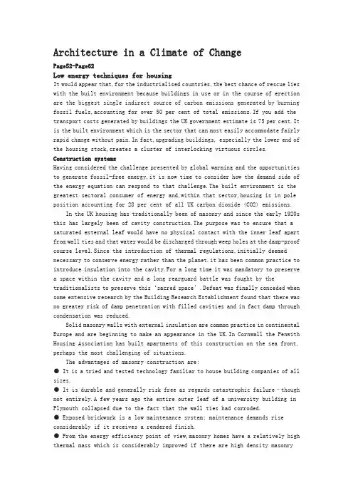
Architecture in a Climate of ChangePage52-Page62Low energy techniques for housingIt would appear that,for the industrialised countries,the best chance of rescue lies with the built environment because buildings in use or in the course of erection are the biggest single indirect source of carbon emissions generated by burning fossil fuels,accounting for over 50 per cent of total emissions.If you add the transport costs generated by buildings the UK government estimate is 75 per cent.It is the built environment which is the sector that can most easily accommodate fairly rapid change without pain.In fact,upgrading buildings, especially the lower end of the housing stock,creates a cluster of interlocking virtuous circles. Construction systemsHaving considered the challenge presented by global warming and the opportunities to generate fossil-free energy,it is now time to consider how the demand side of the energy equation can respond to that challenge.The built environment is the greatest sectoral consumer of energy and,within that sector,housing is in pole position accounting for 28 per cent of all UK carbon dioxide (CO2) emissions.In the UK housing has traditionally been of masonry and since the early 1920s this has largely been of cavity construction.The purpose was to ensure that a saturated external leaf would have no physical contact with the inner leaf apart from wall ties and that water would be discharged through weep holes at the damp-proof course level.Since the introduction of thermal regulations,initially deemed necessary to conserve energy rather than the planet,it has been common practice to introduce insulation into the cavity.For a long time it was mandatory to preserve a space within the cavity and a long rearguard battle was fought by the traditionalists to preserve this‘sacred space’.Defeat was finally conceded when some extensive research by the Building Research Establishment found that there was no greater risk of damp penetration with filled cavities and in fact damp through condensation was reduced.Solid masonry walls with external insulation are common practice in continental Europe and are beginning to make an appearance in the UK.In Cornwall the Penwith Housing Association has built apartments of this construction on the sea front, perhaps the most challenging of situations.The advantages of masonry construction are:● It is a tried and tested technology familiar to house building companies of all sizes.● It is durable and generally risk free as regards catastrophic failure–though not entirely.A few years ago the entire outer leaf of a university building in Plymouth collapsed due to the fact that the wall ties had corroded.● Exposed brickwork is a low maintenance system; maintenance demands rise considerably if it receives a rendered finish.● From the energy efficiency point of view,masonry homes have a relatively high thermal mass which is considerably improved if there are high density masonryinternal walls and concrete floors.Framed constructionVolume house builders are increasingly resorting to timber-framed construction with a brick outer skin,making them appear identical to full masonry construction.The attraction is the speed of erection especially when elements are fabricated off site. However,there is an unfortunate history behind this system due to shortcomings in quality control.This can apply to timber which has not been adequately cured or seasoned.Framed buildings need to have a vapour barrier to walls as well as roofs. With timber framing it is difficult to avoid piercing the barrier.There can also be problems achieving internal fixings.For the purist,the ultimate criticism is that it is illogical to have a framed building clad in masonry when it cries out for a panel,boarded,slate or tile hung external finish.Pressed steel frames for homes are now being vigorously promoted by the steel industry.The selling point is again speed of erection but with the added benefit of a guaranteed quality in terms of strength and durability of the material.From the energy point of view,framed buildings can accommodate high levels of insulation but have relatively poor thermal mass unless this is provided by floors and internal walls.Innovative techniquesPermanent Insulation Formwork Systems (PIFS) are beginning to make an appearance in Britain.The principle behind PIFS is the use of precision moulded interlocking hollow blocks made from an insulation material,usually expanded polystyrene.They can be rapidly assembled on site and then filled with pump grade concrete.When the concrete has set the result is a highly insulated wall ready for the installation of services and internal and exterior finishes.They can achieve a U-value as low as 0.11 W/m2K.Above three storeys the addition of steel reinforcement is necessary. The advantages of this system are:● Design flexibility; almost any plan shape is possible.● Ease and speed of erection;skill requirements are modest which is why it has proved popular with the self-build sector.Experienced erectors can achieve 5 m2 per man hour for erection and placement of concrete.● The finished product has high structural strength together with considerable thermal mass and high insulation value.Solar designPassive solar designSince the sun drives every aspect of the climate it is logical to describe the techniques adopted in buildings to take advantage of this fact as‘solar design’. The most basic response is referred to as‘passive solar design’.In this case buildings are designed to take full advantage of solar gain without any intermediate operations.Access to solar radiation is determined by a number of conditions:● the sun’s position relative to the principal facades of the building(solar altitude and azimuth);● site orientation and slope;● existing obstructions on the site;● potential for overshadowing from obstructions outside the site boundary.One of the methods by which solar access can be evaluated is the use of some form of sun chart.Most often used is the stereographic sun chart in which a series of radiating lines and concentric circles allow the position of nearby obstructions to insolation,such as other buildings,to be plotted.On the same chart a series of sun path trajectories are also drawn(usually one arc for the 21st day of each month); also marked are the times of the day.The intersection of the obstructions’outlines and the solar trajectories indicate times of transition between sunlight and shade. Normally a different chart is constructed for use at different latitudes (at about two degree intervals).Sunlight and shade patterns cast by the proposed building itself should also be considered.Graphical and computer prediction techniques may be employed as well as techniques such as the testing of physical models with a heliodon.Computer modelling of shadows cast by the sun from any position is offered by Integrated Environmental Solutions (IES) with its‘Suncast’program.This is a user-friendly program which should be well within normal undergraduate competence. The spacing between buildings is important if overshading is to be avoided during winter months when the benefit of solar heat gain reaches its peak.On sloping sites there is a critical relationship between the angle of slope and the level of overshading.For example, if overshading is to be avoided at a latitude of 50 N,rows of houses on a 10 north-facing slope must be more than twice as far apart than on 10 south-facing slope.Trees can obviously obstruct sunlight.However,if they are deciduous,they perform the dual function of permitting solar penetration during the winter whilst providing a degree of shading in the summer.Again spacing between trees and buildings is critical.Passive solar design can be divided into three broad categories:● direct gain;● indirect gain;● attached sunspace or conservatory.Each of the three categories relies in a different way on the‘greenhouse effect’as a means of absorbing and retaining heat.The greenhouse effect in buildings is that process which is mimicked by global environmental warming.In buildings,the incident solar radiation is transmitted by facade glazing to the interior where it is absorbed by the internal surfaces causing warming.However,re-emission of heat back through the glazing is blocked by the fact that the radiation is of a much longer wavelength than the incoming radiation.This is because the re-emission is from surfaces at a much lower temperature and the glazing reflects back such radiation to the interior.Direct gainDirect gain is the design technique in which one attempts to concentrate the majority of the building’s glazing on the sun-facing facade.Solar radiation is admitted directly into the space concerned.Two examples 30 years apart are the author’s housein Sheffield,designed in 1967 and the Hockerton Project of 1998 by Robert and Brenda Vale.The main design characteristics are:● Apertures through which sunlight is admitted should be on the solar side of the building, within about 30 of south for the northern hemisphere.● Windows facing west may pose a summer overheating risk.● Windows should be at least double glazed with low emissivity glass (Low E) as now required by the UK Building Regulations.● The main occupied living spaces should be located on the solar side of the building.● The floor should be of a high thermal mass to absorb the heat and provide thermal inertia,which reduces temperature fluctuations inside the building.● As regards the benefits of thermal mass,for the normal daily cycle of heat absorption and emission,it is only about the first 100 mm of thickness which is involved in the storage process.Thickness greater than this provides marginal improvements in performance but can be useful in some longer-term storage options.● In the case of solid floors,insulation should be beneath the slab.● A vapour barrier should always be on the warm side of any insulation.● Thick carpets should be avoided over the main sunlit and heatabsorbing portion of the floor if it serves as a thermal store.However,with suspended timber floors a carpet is an advantage in excluding draughts from a ventilated underfloor zone. During the day and into the evening the warmed floor should slowly release its heat, and the time period over which it happens makes it a very suitable match to domestic circumstances when the main demand for heat is in the early evening.As far as the glazing is concerned,the following features are recommended: ● Use of external shutters and/or internal insulating panels might be considered to reduce night-time heat loss.● To reduce the potential of overheating in the summer,shading may be provided by designing deep eaves or external louvres. Internal blinds are the most common technique but have the disadvantage of absorbing radiant heat thus adding to the internal temperature.● Heat reflecting or absorbing glass may be used to limit overheating.The downside is that it also reduces heat gain at times of the year when it is beneficial. ● Light shelves can help reduce summer overheating whilst improving daylight distribution.Direct gain is also possible through the glazing located between the building interior and attached sunspace or conservatory;it also takes place through upper level windows of clerestory designs.In each of these cases some consideration is required concerning the nature and position of the absorbing surfaces.In the UK climate and latitude as a general rule of thumb room depth should not be more than two and a half times the window head height and the glazing area should be between about 25 and 35 per cent of the floor area.Indirect gainIn this form of design a heat absorbing element is inserted between the incident solar radiation and the space to be heated;thus the heat is transferred in an indirectway.This often consists of a wall placed behind glazing facing towards the sun,and this thermal storage wall controls the flow of heat into the building.The main elements● High thermal mass element positioned between sun and internal spaces,the heat absorbed slowly conducts across the wall and is liberated to the interior some time later.● Materials and thickness of the wall are chosen to modify the heat flow.In homes the flow can be delayed so that it arrives in the evening matched to occupancy periods. Typical thicknesses of the thermal wall are 20–30 cm.● Glazing on the outer side of the thermal wall is used to provide some insulation against heat loss and help retain the solar gain by making use of the greenhouse effect.● The area of the thermal storage wall element should be about 15–20 per cent of the floor area of the space into which it emits heat.● In order to derive more immediate heat benefit,air can be circulated from the building through the air gap between wall and glazing and back into the room.In this modified form this element is usually referred to as a Trombe wall. Heat reflecting blinds should be inserted between the glazing and the thermal wall to limit heat build-up in summer.In countries which receive inconsistent levels of solar radiation throughout the day because of climatic factors (such as in the UK),the option to circulate air is likely to be of greater benefit than awaiting its arrival after passage through the thermal storage wall.At times of excess heat gain the system can provide alternative benefits with the air circulation vented directly to the exterior carrying away its heat,at the same time drawing in outside air to the building from cooler external spaces.Indirect gain options are often viewed as being the least aesthetically pleasing of the passive solar options,partly because of the restrictions on position and view out from remaining windows,and partly as a result of the implied dark surface finishes of the absorbing surfaces.As a result,this category of the three prime solar design technologies is not as widely used as its efficiency and effectiveness would suggest.Attached sunspace/conservatoryThis has become a popular feature in both new housing and as an addition to existing homes.It can function as an extension of living space,a solar heat store,a preheater for ventilation air or simply an adjunct greenhouse for plants.On balance it is considered that conservatories are a net contributor to global warming since they are often heated.Ideally the sunspace should be capable of being isolated from the main building to reduce heat loss in winter and excessive gain in summer.The area of glazing in the sunspace should be 20–30 per cent of the area of the room to which it is attached.The most adventurous sunspace so far encountered is in the Hockerton housing development which will feature later.Ideally the summer heat gain should be used to charge a seasonal thermal storage element to provide background warmth in winter.At the very least,air flow paths between the conservatory and the main building should be carefully controlled.Active solar thermal systemsA distinction must be drawn between passive means of utilising the thermal heat of the sun, discussed earlier,and those of a more‘active’nature Active systems take solar gain a step further than passive solar.They convert direct solar radiation into another form of energy.Solar collectors preheat water using a closed circuit calorifier.The emergence of Legionella has highlighted the need to store hot water at a temperature above 60 C which means that for most of the year in temperate climes active solar heating must be supplemented by some form of heating.Active systems are able to deliver high quality energy.However,a penalty is incurred since energy is required to control and operate the system known as the ‘parasitic energy requirement’.A further distinction is the difference between systems using the thermal heat of the sun,and systems,such as photovoltaic cells, which convert solar energy directly into electrical power.For solar energy to realise its full potential it needs to be installed on a district basis and coupled with seasonal storage.One of the largest projects is at Friedrichshafen.The heat from 5600 m2 of solar collectors on the roofs of eight housing blocks containing 570 apartments is transported to a central heating unit or substation.It is then distributed to the apartments as required.The heated living area amounts to 39 500 m2.Surplus summer heat is directed to the seasonal heat store which,in this case, is of the hot water variety capable of storing 12 000 m3.The scale of this storage facility is indicated by Figure 5.9.The heat delivery of the system amounts to 1915 MWh/year and the solar fraction is 47 per cent.The month by month ratio between solar and fossil-based energy indicates that from April to November inclusive,solar energy accounts for almost total demand,being principally domestic hot water.In places with high average temperatures and generous sunlight,active solar has considerable potential not just for heating water but also for electricity generation.This has particular relevance to less and least developed countries.环境变化影响下的建筑学房屋设计中的低能耗技术显而易见,在工业化国家,最好的营救机会依赖于建筑环境,因为不论是在使用的建筑或者是在建设的建筑,都是最大的、单一的、间接地由化石燃料的燃烧所引起的碳排放的源头,而这些站了所有排放的50%。
forced concrete structure reinforced with anoverviewReinSince the reform and opening up, with the national economy's rapid and sustained development of a reinforced concrete structure built, reinforced with the development of technology has been great. Therefore, to promote the use of advanced technology reinforced connecting to improve project quality and speed up the pace of construction, improve labor productivity, reduce costs, and is of great significance.Reinforced steel bars connecting technologies can be divided into two broad categories linking welding machinery and steel. There are six types of welding steel welding methods, and some apply to the prefabricated plant, and some apply to the construction site, some of both apply. There are three types of machinery commonly used reinforcement linking method primarily applicable to the construction site. Ways has its own characteristics and different application, and in the continuous development and improvement. In actual production, should be based on specific conditions of work, working environment and technical requirements, the choice of suitable methods to achieve the best overall efficiency.1、 steel mechanical link1.1 radial squeeze linkWill be a steel sleeve in two sets to the highly-reinforced Department with superhigh pressure hydraulic equipment (squeeze tongs) along steel sleeve radial squeeze steel casing, in squeezing out tongs squeeze pressure role of a steel sleeve plasticity deformation closely integrated with reinforced through reinforced steel sleeve and Wang Liang's Position will be two solid steel bars linkedCharacteristic: Connect intensity to be high, performance reliable, can bear high stress draw and pigeonhole the load and tired load repeatedly.Easy and simple to handle, construction fast, save energy and material, comprehensive economy profitable, this method has been already a large amount of application in the project.Applicable scope : Suitable for Ⅱ , Ⅲ , Ⅳ grade reinforcing bar (including welding bad reinforcing bar ) with ribbing of Ф 18- 50mm, connection between the same diameter or different diameters reinforcing bar .1.2 must squeeze linkExtruders used in the covers, reinforced axis along the cold metal sleeve squeeze dedicated to insert sleeve Lane two hot rolling steel drums into a highly integrated mechanical linking methods.Characteristic: Easy to operate and joining fast and not having flame homework , can construct for 24 hours , save a large number of reinforcing bars and energy.Applicable scope : Suitable for , set up according to first and second class antidetonation requirement -proof armored concrete structure ФⅡ , Ⅲ grade reinforcing bar with ribbing of hot rolling of 20- 32mm join and construct live.1.3 cone thread connectingUsing cone thread to bear pulled, pressed both effort and self-locking nature, undergo good principles will be reinforced by linking into cone-processing thread at the moment the value of integration into the joints connecting steel bars.Characteristic: Simple , all right preparatory cut of the craft , connecting fast, concentricity is good, have pattern person who restrain from advantage reinforcing bar carbon content.Applicable scope : Suitable for the concrete structure of the industry , civil building and general structures, reinforcing bar diameter is for Фfor the the 16- 40mm one Ⅱ , Ⅲ grade verticality, it is the oblique to or reinforcing bars horizontal join construct live.conclusionsThese are now commonly used to connect steel synthesis methods, which links technology in the United States, Britain, Japan and other countries are widely used. There are different ways to connect their different characteristics and scope of the actual construction of production depending on the specific project choose a suitable method of connecting to achieve both energy conservation and saving time limit for a project ends.钢筋混凝土结构中钢筋连接综述改革开放以来,随着国民经济的快速、持久发展,各种钢筋混凝土建筑结构大量建造,钢筋连接技术得到很大的发展。
文献信息文献标题:Exploitation and Benefits of BIM in Construction Project Management(建筑信息模型(BIM)在建设工程项目管理中的开发与效益)文献作者:Peter Mesároš,Tomáš Mandičák文献出处:《IOP Conference Series: Materials Science and Engineering. IOP Publishing》,2017,245(6):062056.字数统计:英文2319单词,12930字符;中文3709汉字外文文献Exploitation and Benefits of BIM in Construction ProjectManagementAbstract BIM is increasingly getting into the awareness in construction industry. BIM is the process of creating and data managing of the building during its life cycle. BIM became a part of management tools in modern construction companies. Construction projects have a number of participants. It means difficulty process of construction project management and a serious requirement for processing the huge amount of information including design, construction, time and cost parameters, economic efficiency and sustainability. Progressive information and communication technologies support cost management and management of construction project. One of them is Building Information Modelling. Aim of the paper is to examine the impact of BIM exploitation and benefits on construction project management in Slovak companies.1.IntroductionThe exploitation of progressive technologies in the construction project management represents a greater potential each day. The possibility of using new technologies in construction project management (especially for cost management,cost reducing, design of buildings, drawing and planning of construction projects generally) is steadily increasing by developing of new software solutions. According to Mesároš et al., cost management is therefore an essential condition for the effective management of construction projects. In fact, the cost reducing is not the only one benefit of exploitation progressive technology. According to other researchers, it is nowadays necessary to analyse the other benefits that new technologies bring in every area. In construction project management, BIM technology is one of the possible and available solutions for the above mentioned tasks.BIM (Building Information Modelling) therefore was generally mentioned and defined in a number of publications, conferences and workshops. Other authors ware talking about BIM like the term that is increasingly getting into the awareness in construction industry. The first mention of the BIM concept was recorded in 2002. Very often, the concept of BIM is perceived as a computer program or a 3D model that is only part of it. BIM concept has several definitions. Building information modelling is the process of creating and data managing about the building model during its life cycle. According to National Institute of Building Science, information obtained through information modelling are crucial for effective and accurate design of construction documents, construction planning, cost estimating and predicting traffic building. Information modelling thus not only creates a 3D model, but 4D (time), 5D (cost) and XD model. In addition, it is possible to say that BIM is the tool for managing relations between the participants a construction project. BIM is currently the most common denomination for a new way of approaching the design, construction and maintenance of buildings.Due to the overview of available resources and of the discussion of BIM, it may seem that we shall all was said about BIM and that this tool is often used. There is a question whether this is actually true. Do the construction companies really use this tool as spoken about? And what is perception of construction companies on BIM tool? What are benefits of exploitation of BIM? There are only a few questions, that are necessary discusses in BIM topic. That is basic of this research problem, what was formulated to these research questions:▪What are benefits of BIM using?▪What is perception of this benefits by construction companies?▪What is exploitation level of BIM in construction companies?▪What is impact on the biggest benefit of BIM using?There are some questions that is necessary to find the answers, when we are analysing the issue of BIM in selected market or environment in construction project management.2.Literature reviewThe issue of BIM is devoted to a series of authors. In terms of the status of basic research questions it is the right to talk primarily about research aimed on benefits of using BIM technology. According a lot of studies and investigations, cost reducing is one of the biggest benefit of BIM exploitation. Next benefits was set as time reducing, productivity increasing and more. One of the biggest benefit of BIM exploitation in construction project are cost reducing and control. It represents 60 % of respondents in their research.The other authors were talking about benefits in their investigation too. They mentioned s mainly budget aspect and design aspect as main benefit.Between mainly benefits of BIM exploitation it can be possible include time reducing and cost reducing in construction project management. It confirmed research realised by Ian and Damian. In addition to the above benefits, the authors mentioned the saving of human resources.Other research study confirmed savings of project cost by using of BIM. The biggest benefit is time reducing in schedule preparing trough BIM technology. This research described possibilities of measurement in the issue of BIM exploitation and benefits. The main area of investigation for measurement of BIM benefits was specified. Between main area it was selected by research results especially area: changes to processes, IT investments to supported improvements, business performance improvements and improved profit and ROI. Overview of selected researches and investigation is more detailed described in table 1.Table 1. Overview of selected researches and investigation on benefits of BIM exploitationBased on a lot of researches and literature resources about benefits of BIM, the list of main benefits was done for purposes of this research:▪cost reducing in construction project management▪time reducing in project documentation,▪time reducing for the entire lifecycle of the construction project, including the design phase,▪faster access to information and relevant documents all participants of construction project,▪increasing of employee productivity,▪increasing of financial control,▪support and facilitate of decision-making,▪increasing the quality of the documents, the elimination of error documentation,▪elimination of errors in the construction process – increasing of construction quality,▪increasing revenues from contracts.3.Methodology3.1.Research questions and aimsBased on the evaluation of the current state of art, basic research questions were raised:▪What are benefits of BIM using?▪What is perception of this benefits by construction companies?▪What is exploitation level of BIM in construction companies?▪What is impact on the biggest benefit of BIM using?The subject of research was Slovak construction industry. Construction project management and BIM exploitation in Slovakia is not well researched, despite frequent discussions on this issue.Based on the determination of research questions, the research objectives have been set. Main objective of this research was to analyze and quantify the benefits of BIM using in terms of Slovak construction project management. Another aim of research was to examine the exploitation of BIM tool is in Slovak construction industry. Based on this aims of research, the partial aim was set: answer to the question “what is impact of the biggest benefit of BIM using on construction project management”.3.2.Data collection and research sampleData collection was conducted by the questionnaire. Questionnaire was designed and distributed in electronic form. Questionnaire was produced by online platform FORMEES in electronic form. The research sample was approached by e-mail with the request to participate in the research. Total were interviewed 1276 of respondents(construction companies in Slovakia). It participated in the questionnaire survey 85 respondents. It represents a return of 6.66%. Generally, it is possible to return to the level of 4.31% is considered as good. Research sample is more described in Table 2.Table 2. Research sample3.3.Data processing methodData were evaluated based on several statistical methods through software STATISTICA version 12. When processing the results of research conducted within the research, mostly descriptive and inductive statistics were used. When evaluating the results of the research areas, importance index was used on the basis of which the ranking of benefits of using BIM technology has been compiled. This importance index was used by Mutesi and Kyakula in research of ICT benefits in construction industry.Index importance is determined by the relationship Ii = (Σ wi. F XI) 100 / 5n, wherein:Ii - Importance indexwi - weight is based on the Likert scale (1-5) (the weight given to response; I =1, 2, 3, 4 or 5 is response frequency = very weak/low)F XI- Response raten - Number of respondentsDue to the nature of the problem and the main objective of the paper appropriatestatistical methods that can detect and analyses relationships between research groups -Kruskal-Wallis test was selected. To determine the answer was used “Likert scale ranging” from 1 to 5 on the basis of fixed values the arithmetic average of the values has been done for the selected area under consideration. It means performance of companies. 1 - is very low performance and 5 - is the very high performance. This data was comparison with cost reducing indicator and profit.4.Discussion and resultsThe issue of use of BIM technology as already outlined, it is current topic. This research had among others to answer to the question: How BIM is used in the Slovak construction industry. This state is shown in Figure 1.Figure 1. Exploitation of BIM technology in construction project management in SlovakiaIn spite of often discusses of BIM technology, it is using in a low rate. Only 24.71 % respondents are using BIM technology in construction project management. It is very low value. A lot of construction companies do not use BIM technology. These companies try the quantifying benefits of BIM exploitation. All results are in Table 3.Table 3.Ranking of BIM benefits in Slovak construction project managementThe biggest benefit of BIM exploitation presents cost reducing in construction project management. It achieved 89.34% importance index. In comparison with other research in other countries, that´s not surprising. The second biggest benefit of use of BIM technology represents increasing the quality of the documents and elimination of error in documentation. Importance index of this benefit is on level of 87.56%. Other benefits are increasing of financial control, time reducing in project documentation, faster access to information and relevant documents all participants of construction project, faster access to information and relevant documents all participants of construction project, elimination of errors in the construction process – increasing of construction quality and time reducing for the entire lifecycle of the construction project, including the design phase. All of these benefits achieved more than 50%. Next benefits didn't achieve more than 50%. This ranking of benefits shown main advantages and quantifying these advantages based on Slovak construction companies. This ranking shows the biggest benefit of BIM exploitation. It is very necessary explores the impact BIM exploitation to cost reducing. Next figures describes impact rate of BIM exploitation to cost reducing.Figure 2. Impact rate of BIM exploitation to cost reducing in construction project management inSlovakiaThis research confirmed impact BIM to cost reducing. Companies used BIM technology achieved bigger impact rate than companies don't use BIM technology. BIM technology has impact to cost reducing. This is often reason, why this companies want to implement BIM technology.5.ConclusionsBIM technology offered a lot of functionality and it ́s very helpful tool in construction project management. Cost management is very important part of construction project management. Accurate and information based cost management may have a serious impact on the success of construction project. BIM technology has a lot of functionality, includes cost management too. Research tried to provide the answers to benefits of BIM technology. Ranking of benefits was based on Slovak construction companies. As examined, quality of documentation and cost reducing are the biggest benefit of BIM technology.中文译文建筑信息模型(BIM)在建设工程项目管理中的开发与效益摘要建筑信息模型(BIM)越来越受到建筑业的重视。
高层建筑中英文对照外文翻译文献中英文对照外文翻译文献英文原文Components of A Building and Tall Buildings1. AbstractMaterials and structural forms are combined to make up the various parts of a building, including the load-carrying frame, skin, floors, and partitions. The building also has mechanical and electrical systems, such as elevators, heating and cooling systems, and lighting systems. The superstructure is that part of a building above ground, and the substructure and foundation is that part of a building below ground.The skyscraper owes its existence to two developments of the 19th century: steel skeleton construction and the passenger elevator. Steel as a construction material dates from the introduction of the Bessemer converter in 1885.Gustave Eiffel (1832-1932) introduced steel construction in France. His designs for the Galerie des Machines and the Tower for the Paris Exposition of 1889 expressed the lightness of the steel framework. The Eiffel Tower, 984 feet (300 meters) high, was the tallest structure built by man and was not surpassed until 40 years later by a series of American skyscrapers.Elisha Otis installed the first elevator in a department store in New York in 1857.In 1889, Eiffel installed the first elevators on a grand scale in the Eiffel Tower, whose hydraulic elevators could transport 2,350 passengers to the summit every hour.2. Load-Carrying FrameUntil the late 19th century, the exterior walls of a building were used as bearing walls to support the floors. Thisconstruction is essentially a post and lintel type, and it is still used in frame construction for houses. Bearing-wall construction limited the height of building because of the enormous wall thickness required;for instance, the 16-story Monadnock Buildi ng built in the 1880’s in Chicago had walls 5 feet (1.5 meters) thick at the lower floors. In 1883, William Le Baron Jenney (1832-1907) supported floors on cast-iron columns to form a cage-like construction. Skeleton construction, consisting of steel beams and columns, was first used in 1889. As a consequence of skeleton construction, the enclosing walls become a “curtain wall” rather than serving a supporting function. Masonry was the curtain wall material until the 1930’s, when light metal and glass curta in walls were used. After the introduction of buildings continued to increase rapidly.All tall buildings were built with a skeleton of steel until World War Ⅱ. After thewar, the shortage of steel and the improved quality of concrete led to tall building being built of reinforced concrete. Marina Tower (1962) in Chicago is the tallest concrete building in the United States;its height—588 feet (179 meters)—is exceeded by the 650-foot (198-meter) Post Office Tower in London and by other towers.A change in attitude about skyscraper construction has brought a return to the use of the bearing wall. In New York City, the Columbia Broadcasting System Building, designed by Eero Saarinen in 1962,has a perimeter wall consisting of 5-foot (1.5meter) wide concrete columns spaced 10 feet (3 meters) from column center to center. This perimeter wall, in effect, constitutes a bearing wall. One reason for this trend is that stiffness against the action of wind can be economically obtained by using thewalls of the building as a tube;the World Trade Center building is another example of this tube approach. In contrast, rigid frames or vertical trusses are usually provided to give lateral stability.3. SkinThe skin of a building consists of both transparent elements (windows) and opaque elements (walls). Windows are traditionally glass, although plastics are being used, especially in schools where breakage creates a maintenance problem. The wall elements, which are used to cover the structure and are supported by it, are built of a variety of materials: brick, precast concrete, stone, opaque glass, plastics, steel, and aluminum. Wood is used mainly in house construction;it is not generally used for commercial, industrial, or public building because of the fire hazard.4. FloorsThe construction of the floors in a building depends on the basic structural frame that is used. In steel skeleton construction, floors are either slabs of concrete resting on steel beams or a deck consisting of corrugated steel with a concrete topping. In concrete construction, the floors are either slabs of concrete on concrete beams or a series of closely spaced concrete beams (ribs) in two directions topped with a thin concrete slab, giving the appearance of a waffle on its underside. The kind of floor that is used depends on the span between supporting columns or walls and the function of the space. In an apartment building, for instance, where walls and columns are spaced at 12 to 18 feet (3.7 to 5.5 meters), the most popular construction is a solid concrete slab with no beams. The underside of the slab serves as the ceiling for the space below it. Corrugated steel decks areoften used in office buildings because the corrugations, when enclosed by another sheet of metal, form ducts for telephone and electrical lines.5. Mechanical and Electrical SystemsA modern building not only contains the space for which it is intended (office, classroom, apartment) but also contains ancillary space for mechanical and electrical systems that help to provide a comfortable environment. These ancillary spaces in a skyscraper office building may constitute 25% of the total building area. The importance of heating, ventilating, electrical, and plumbing systems in an office building is shown by the fact that 40% of the construction budget is allocated to them. Because of the increased use of sealed building with windows that cannot be opened, elaborate mechanical systems are provided for ventilation and air conditioning. Ducts and pipes carry fresh air from central fan rooms and air conditioning machinery. The ceiling, which is suspended below the upper floor construction, conceals the ductwork and contains the lighting units. Electrical wiring for power and for telephone communication may also be located in this ceiling space or may be buried in the floor construction in pipes or conduits.There have been attempts to incorporate the mechanical and electrical systems into the architecture of building by frankly expressing them;for example, the American Republic Insurance Company Building(1965) in Des Moines, Iowa, exposes both the ducts and the floor structure in an organized and elegant pattern and dispenses with the suspended ceiling. This type of approach makes it possible to reduce the cost of the building and permits innovations, such as in the span of the structure.6. Soils and FoundationsAll building are supported on the ground, and therefore the nature of the soil becomes an extremely important consideration in the design of any building. The design of a foundation dependson many soil factors, such as type of soil, soil stratification, thickness of soil lavers and their compaction, and groundwater conditions. Soils rarely have a single composition;they generally are mixtures in layers of varying thickness. For evaluation, soils are graded according to particle size, which increases from silt to clay to sand to gravel to rock. In general, the larger particle soils will support heavier loads than the smaller ones. The hardest rock can support loads up to 100 tons per square foot(976.5 metric tons/sq meter), but the softest silt can support a load of only 0.25 ton per square foot(2.44 metric tons/sq meter). All soils beneath the surface are in a state of compaction;that is, they are under a pressure that is equal to the weight of the soil column above it. Many soils (except for most sands and gavels) exhibit elastic properties—they deform when compressed under load and rebound when the load is removed. The elasticity of soils is often time-dependent, that is, deformations of the soil occur over a length of time which may vary from minutes to years after a load is imposed. Over a period of time, a building may settle if it imposes a load on the soil greater than the natural compaction weight of the soil. Conversely, a building may heave if it imposes loads on the soil smaller than the natural compaction weight. The soil may also flow under the weight of a building;that is, it tends to be squeezed out.Due to both the compaction and flow effects, buildings tend settle. Uneven settlements, exemplified by the leaning towers in Pisa and Bologna, can have damaging effects—the building maylean, walls and partitions may crack, windows and doors may become inoperative, and, in the extreme, a building may collapse. Uniform settlements are not so serious, although extreme conditions, such as those in Mexico City, can have serious consequences. Over the past 100 years, a change in the groundwater level there has caused some buildings to settle more than 10 feet (3 meters). Because such movements can occur during and after construction, careful analysis of the behavior of soils under a building is vital.The great variability of soils has led to a variety of solutions to the foundation problem. Wherefirm soil exists close to the surface, the simplest solution is to rest columns on a small slab of concrete(spread footing). Where the soil is softer, it is necessary to spread the column load over a greater area;in this case, a continuous slab of concrete(raft or mat) under the whole building is used. In cases where the soil near the surface is unable to support the weight of the building, piles of wood, steel, or concrete are driven down to firm soil.The construction of a building proceeds naturally from the foundation up to the superstructure. The design process, however, proceeds from the roof down to the foundation (in the direction of gravity). In the past, the foundation was not subject to systematic investigation. A scientific approach to the design of foundations has been developed in the 20th century. Karl Terzaghi of the United States pioneered studies that made it possible to make accurate predictions of the behavior of foundations, using the science of soil mechanics coupled with exploration and testing procedures. Foundation failures of the past, such as the classical example of the leaning tower in Pisa,have become almost nonexistent. Foundations still are a hidden but costly part of many buildings.The early development of high-rise buildings began with structural steel framing. Reinforced concrete and stressed-skin tube systems have since been economically and competitively used in a number of structures for both residential and commercial purposes. The high-rise buildings ranging from 50 to 110 stories that are being built all over the United States are the result of innovations and development of new structural systems.Greater height entails increased column and beam sizes to make buildings more rigid so that under wind load they will not sway beyond an acceptable limit. Excessive lateral sway may causeserious recurring damage to partitions, ceilings, and other architectural details. In addition, excessive sway may cause discomfort to the occupants of the building because of their perception of such motion. Structural systems of reinforced concrete, as well as steel, take full advantage of the inherent potential stiffness of the total building and therefore do not require additional stiffening to limit the sway.中文译文建筑及高层建筑的组成1 摘要材料和结构类型是构成建筑物各方面的组成部分,这些部分包括承重结构、围护结构、楼地面和隔墙。
中文译文:建筑业的竞争及竞争策略美国的工程建筑公司几十年来一直控制着国际建筑市场,但近来世界上发生的事件改变了它的主导地位。
为了调查今后十年对工程建筑竞争产生影响的推动力及趋势,由建筑工业研究院的"2000年建筑特别工作组:发起一项称为“2000年建筑市场竞争分析”的研究项目。
该研究项目考察了一些影响竞争的因素,包括下列方面:企业能力塑造:采用纵向联合,横向发展的方法,提高企业的综合能力。
扩大市场领地,这种做法包括被海外的联合企业收购或被其合并,或是由美国公司收购外国公司。
筹措资金的选择方法:私有化作用,建筑权力转让项目,未来市场中工程筹资特征。
管理、组织及结构:未来的经营管理及组织方法、组织结构、组织技巧要有利于引导职员在世界竞争环境中发挥作用。
劳力特征:未来具有专业水平和技工水平的工程建筑工人的供求情况技术问题:技术将如何影响竞争,如何用来弥补劳力不足的缺陷。
研究目标及范围这一研究项目的目标是收集信息,使之为适应2000年及以后的工程建筑业在调整、制定策略方面的需要提供真知灼见,并制定出2000年工程建筑业的可能的发展计划。
这项研究回顾了工程建筑业的历史过程,审视了当前的发展趋势,以确定影响该工业未来的推动力,与该工业相关的有重塑企业能力,私有化及筹措资金方法的潜在作用以及经营管理、组织方法、公司结构方面的未来发展方向。
研究范围包括选定一些公司,采访这些公司有专业特长的人员。
这些人员的专业涉及面很广,包括商业建筑,重工业建筑,公共事业设施建设,基础建设.轻工业建筑,电力,生产程序以及航天科学。
工程建筑业竞争特性工程建筑业的竞争特征由于下列原因在变动:80年代发生的事件,以及计划在90年代实施的项目,正在引导建筑业摆脱相互对立的局面,转向相互合作。
应该以积极的眼光看待新的公司进入国际工程建筑市场,因为它增加了全球合作的机遇。
合作关系会使所有的伙伴受益,这是因为美国公司可以在合作伙伴的国家找到机遇,同样,外国公司也会打入美国市场。
三维建筑模型论文中英文资料对照外文翻译文献三维建筑模型中英文资料Constructing Rules and Scheduling Technology for 3DBuilding ModelsZhengwei SUI, Lun WU, Jingnong WENG, Xing LIN, Xiaolu JIAbstract3D models have become important form of geographic data beyond conventional 2D geospatial data. Buildings are important marks for human to identify their environments, because they are close with human life, particularly in the urban areas. Geographic information can be expressed in a more intuitive and effective manner with architectural models being modeled and visualized in a virtual 3D environment. Architectural model data features with huge data volume, high complexity,non-uniform rules and so on. Hence, the cost of constructing large-scale scenes is high. Meanwhile, computers are lack of processing capacity upon a large number of model data. Therefore, resolving the conflicts between limited processing capacity of computer and massive data of model is valuable. By investigating the characteristics of buildings and the regular changes of viewpoint in virtual 3D environment, this article introduces several constructing rules and scheduling techniques for 3D constructing of buildings, aiming at the reduction of data vol ume and complexity of model and thus improving computers’ efficiency at schedul ing large amount of architectural models. In order to evaluate the efficiency of proposed constructing rules and scheduling technology listed in the above text, the authors carry out a case study by 3D constructing the campus of PekingUniversity using the proposed method and the traditional method. The two results are then examined and compared from aspects of model data volume, model factuality, speed of model loading, average responding time during visualization, compatibility and reusability in 3D geo-visualization platforms: China Star, one China’s own platform for 3D global GIS manufactured by the authors of this paper. The result of comparison reveals that models built by the proposed methods are much better than those built using traditional methods. For the constructing of building objects in large-scale scenes, the proposed methods can not only reduce the complexity and amount of model data remarkably, but can also improving computers’ efficiency.Keywords:Constructing rules, Model scheduling, 3D buildingsI. INTRODUCTIONIn recent years, with the development of 3D GIS (Geographical Information System) software like Google Earth, Skyline, NASA World Wind, large-scale 3D building models with regional characteristics have become important form of geographic data beyond conventional 2D geospatial data, like multi-resolution remote sensing images and vector data [1].Compared to traditional 2D representation, geographic information can be expressed in a more intuitive and effective manner with architectural models being modeled and visualized in a virtual 3D environment. 3D representation and visualization provides better visual effect and vivid urban geographic information, and thus plays an important role in people's perceptions of their environment. Meanwhile, the 3D building data is also of great significance for the construction of digitalcities.But how to efficiently visualize thousands of 3D building models in a virtual 3D environment is not a trivial question. The most difficult part of the question is the conflicts between limited processing capacity of computer and massive volume of model data, particularly in the procedure of model rendering. T aking the 3D modelingof a city for the example using traditional 3D modeling method, suppose there are 100 000 buildings to model in the urban area and the average size of model data for each building is roughly 10 M. So the total data volume of building models in the city could reach a TB level. However, the capacity of ordinary computer memory is only in the GB scale. Based on this concern, the authors proposed the scheduling technology for large-scale 3D buildings models in aspects of model loading and rendering. Due to the lack of building constructing rules and standard, models of buildings vary in aspects of constructing methods, textures collection and model data volume, especially in aspects of model reusability and factuality. Such a large amount of data without uniform constructing rules becomes a huge challenge for data storage, processing and visualization in computers. It also brings the problem of incompatibility among different 3D GIS systems.After years of research in GIS (Geographic Information System), people have accumulated a number of ways to solve the above problems [3]. However in virtual 3D environment, because of the difference in data organization and manners of human computer interaction (HCI), we need to apply a new standardized method of modeling and scheduling for 3D models. At present, there is no such a uniform method as the constructingspecification or standard for the modeling of 3D buildings. Existing approaches are insufficient and inefficient in the scheduling of large-scale building models, resulting in poor performance or large memory occupancy. In response to such questions, the authors proposed a new method for the construction of 3D building models. Models built using the proposed methods could be much better than those built using traditional methods. For the 3D modeling of building objects in scenes of large scale, the proposed methods can not only remarkably reduce the complexity and amount of model data, but can also improving the reusability and factuality of models. Concerning the scheduling of large-scale building models, the Model Loading Judgment Algorithm (MLJA) proposed in this paper could solve the optimal judgment problem of model loading in 3D vision cone, particularly in circumstance with uncertain user interactions.This paper first examines and analyzes existing problems in constructing andscheduling steps of 3D building models. Then the authors propose a set of constructing rules for 3D building models together with methods of model optimization. Besides, special scheduling technology and optimization method for model rendering is also applied in this paper for large-scale 3D building models. In order to evaluate the efficiency of proposed rules and methods, a case study is undertaken by constructing a 3D model for the main campus of Peking University and Shenzhen using both the proposed method and the traditional method respectively. The two resulting 3D models of Peking University campus and Shenzhen are then examined and compared with one other in aspects of model data volume, model factuality,speed of model loading, average responding time during visualization, compatibility and reusability in various 3D geo-visualization platforms like China Star (one China’s own platform for 3D global GIS manufactured by the authors), Skyline, etc. Result of comparison tells that provided similar factuality of models, using the proposed method of us, the data volume of models was reduced by 86%; the speed of model loading was increased by 70%; the average responding time of model during visualization and interaction speed was reduced by 83%. Meanwhile, the compatibility and reusability of 3D model data are also improved if they are constructed using our approach.II. MODELING RULES OF 3D BUILDINGS 3D scene is the best form of visualization for digital city systems. While constructing 3D models for buildings objects, proper methods and rules should be used, which are made with full concerns of the characteristics of 3D building models [2]. The resulting models should be robust, reusable and suitable enough for transmission over computer network, and should at the same time be automatically adapted to system capability.Generally speaking, methods of constructing 3D building models can be classified into three types: wireframe modeling, surface modeling and solid modeling. In normal circumstances, to model buildings in 3D format, the framework of building should be constructed first according to the contour features, number of floors, floorheight, aerial photograph and liveaction photos of buildings. Then, gather the characteristics of scene that the buildings to model are representing. Important characteristics include buildings aerial photograph or liveaction shooting photos. Finally, map the gathered texture to model framework, optimize themodel and create database of the 3D building models.Although there have already been many approaches for the construction of 3D building models, a unified modeling method and rules are still needed to improve the efficiency, quality, facilitate checking, reusability and archiving of constructed models. By investigating the characteristics of buildings, we found that buildings have regular geometric solid for modeling, similar texture on the surfaces of different directions, high similarity in small-scale models of buildings, etc. According to these, this article gives a discussion on the modeling rules from three aspects, including constructing rules of the 3D building models, texture mapping rules of 3D building models and optimization method for constructed models based on mentioned constructing rules.A. Constructing rules of the 3D building modelsThe 3D building modeling refers to the procedure of representing true buildings from the real world into computer in the form of 3D objects [4]. Human beings, as the creator and at the same time potential users of models, play a key role in this procedure. People are different from each other in the understanding of the building objects, methods of modeling and the software tools they use for modeling. Such differences among people who carry out modeling work at the same time lead to the 3D models of diverse quality and low efficiency. So the 3D building constructing rules proposed in this article become necessary and helpful to solve the above problems.1) Combine similar floors as a whole and keep the roof independent2) Share similar models and process the details especially3) Constructing in the unit of meters4) Define central point of the model5) Unified model codes6) Reduce number of surfaces in a single model7) Reduce combination of the models8) Rational split of modelsB. Texture mapping rules of 3D buildingsBased on the framework of 3D models, we need to attach these models with proper textures to create a better visualization effect for 3D buildings. The quality of texture mapping has a direct impact on the visual effect of the scene whiling being rendered [5]. Since the graphics card of computer will load all the textures together when rendering a model, texture mapping rules and the quality of the texture mapping can directly influence the efficiency of rendering as well.C. Optimization of models based on constructing rulesBased on constructing rules and the characteristics of 3D building models, the authors develop a software tool to optimize the 3D building models automatically. The optimizations impl emented in the software tool contain the deletion of models’ internal textures, merging adjacent vertices/lines/surfaces, removing un-mapped framework and so on. Besides, the software can enhance the shape of the whole model, texture position and model facticity in the procedure of model optimization.III. SCHEDULING TECHNOLOGY OF LARGE-SCALE 3DBUILDING MODELSFor the 3D visualization of large-scale architectural models, a series of measures could be applied to ensure the efficient rendering of models. Important measures includes the scene organization, vision cone cutting, elimination of textures on thebackside of models, Shader optimization, LOD Algorithm, math library optimization, memory allocation optimization, etc..How to display thousands of 3D cit y buildings’ models in a virtual 3D environment is not trivial. The main problem is the scheduling of models [7]. It determines when and which models to be loaded. This problem can be divided into two smaller problems: Find visible spatial region of models in 3D environment, and optimization method of model rendering efficiency.A. Find visible spatial region of models in 3D environmentAccording to operating mechanism of computers during 3D visualization and the characteristics of large-scale 3D scene, we need to determine the position of current viewpoint first before loading signal models or urban-unit models. Then in response to the regular changes of viewpoint in virtual 3D environment, the system will preload the 3D model data into memory automatically. In this way, frequent IO operations can be reduced and thus overall efficiency of system gets improved. A new algorithm named MLJA (Model Loading Judgment Algorithm) is proposed in this paper in order to find out visible region of models in the 3D environment. The algorithm integrates the graticules and elevation information to determine the current viewpoint of users in the 3D space. And with the movement of viewpoint, the algorithm schedules the loading of model correspondingly and efficiently.B. Optimization method of model rendering efficiencyThe scheduling method of large-scale 3D building models proposed above is an effective way to solve the problem caused the contradiction between large model data volume and limited capacity of computers. According to the algorithm, we can avoidloading the whole large-scale 3D building models at one time for the sake of limited computer memory, and then improve system efficiency in the procedure of model loading and abandoning. Due to the limited capacity of GPU and local video memory, we need a further research on how to display the loaded model data in more efficient manner. In the remaining part of this paper, the authors will continue to introduce several methods on the optimization of model rendering in the vision cone.1) Elimination of textures on the backside of modelsThe backside of the 3D model is invisible to the users. If we omit the texture mapping for the 3D model on the backside, the processing load of graphic card will be reduced as much as at least 50%. Besides, according to an investigation on procedure of actual model rendering, the authors found that on the backside of the 3D model, the invisible texture is rendered in a counter-clockwise manner against the direction of eyesight, while the visible texture mapping is rendered in clockwise manner. So we can omit the rendering of models which is intended to be rendered incounterclockwise manner. Therefore, the textures won’t exist on the back of 3D models. The graphic card could then work more rapidly and efficiently.2) Eliminate the shielded modelBy calculating the geometric relationship between 3D models in the scene, the shielded models can be omitted while displaying the scene with appropriate shielding patches. Through this way, we can effectively reduce the usage of graphics card memory, and thus achieve higher rendering efficiency and faster 3D virtual system.In the virtual 3D geographic information system, we oftenobserve 3D models from a high altitude. It is especially true for large-scale outdoor 3D models. The usual arrangement of 3D building models are always sparse, however the real block is very small. Therefore, establishing an index for visual control, which is similar to the BSP tree, doesn’t amount to much. Through carefully stud ying DirectX, we found that we can take advantage of the latest Z-buffering technology of DirectX to implement the shielding control of models.3) Optimization method of the Shader instructionsIn shader 3.0 technology, SM (Shader Model) is a model which can optimize the rendering engine. A 3D scene usually contains several shaders. Among these shaders, some deal with the surfaces and skeletons of buildings, and others deal with the texture of 3D building models.Geometry can be handled quickly by shader batch process. The shader can combine similar culmination in 3D building models, deal with the correlation operation of a single vertex, determine the physical shape of the model, link the point, line, triangle and other polygons for a rapid processing while create new polygons, etc. We can assign the computing task to shader and local video memory directly in a very short time without bothering the CPU. In this case, visual effects of smoke, explosions and other special effects and complex graphics are no longer necessary to be processed by the CPU of computer. Such features of shader can speed up both the CPU and graphic card in processing huge amount of 3D models.4) LOD algorithm of large-scale 3D sceneLOD (Level of Detail) is a common and effective solution to resolve theconflicts between real time visualization and the authenticityof models [8]. By investigating the main features and typical algorithms of LOD technology, the authors proposed a new structure for dynamic multi-level display. This structure not only can be applied to the mesh simplification of models with many different but fixed topologies, but also can be applied to the mesh simplification of models with variable topology. Therefore, the LOD technology can be applied to any grid model. Based on the above concerns, the authors also design a mesh simplification algorithm for variable topology through vertices merge. Via the dual operations of vertex merging and splitting, we can achieve smooth transition across different LOD levels of models, and automatically change the model topology.These above techniques plays important role in 3D scene. It can not only enable a rapid visualization of large-scale scene, but also can provide a high-resolution display of scene at a local scale with plenty of architectural details.IV. CONCLUDING REMARKSConstructing rules and scheduling technology plays an important role in the application of large-scale 3D buildings. Since people’s demand for 3D expression brings a challenge of high-efficiency and high-quality to virtual 3D environment, the methods proposed in this article give a good try in these aspects. According to the authors’ research and case studies in this paper, integration of constructing rules and scheduling technology is promising in providing powerful tools to solve the conflicts between limited processing capacity of computer and massive data of models. The result of our case study on Peking University indicates that the proposed new method on constructing rules and scheduling technology for large-scale 3D scene is highly feasible and efficient in practice. The proposedmethods can not only standardize the procedure of model construction, but also can significantly shorten the time taken in scheduling large-scale 3D buildings. It introduces a new effective way to develop applications for large-scale three-dimensional scene.构建三维建筑模型的规则和调度技术隋正伟,邬伦, 翁敬农,林星,季晓璐摘要三维模型已成为超越了传统的二维地理空间数据的一种重要的地理数据形式。
中英文对照外文翻译(文档含英文原文和中文翻译)Create and comprehensive technology in the structure globaldesign of the buildingThe 21st century will be the era that many kinds of disciplines technology coexists , it will form the enormous motive force of promoting the development of building , the building is more and more important too in global design, the architect must seize the opportunity , give full play to the architect's leading role, preside over every building engineering design well. Building there is the global design concept not new of architectural design,characteristic of it for in an all-round way each element not correlated with building- there aren't external environment condition, building , technical equipment,etc. work in coordination with, and create the premium building with the comprehensive new technology to combine together.The premium building is created, must consider sustainable development , namely future requirement , in other words, how save natural resources as much as possible, how about protect the environment that the mankind depends on for existence, how construct through high-quality between architectural design and building, in order to reduce building equipment use quantity andreduce whole expenses of project.The comprehensive new technology is to give full play to the technological specialty of every discipline , create and use the new technology, and with outside space , dimension of the building , working in coordination with in an all-round way the building component, thus reduce equipment investment and operate the expenses.Each success , building of engineering construction condense collective intelligence and strength; It is intelligence and expectation that an architect pays that the building is created; The engineering design of the building is that architecture , structure , equipment speciality compose hardships and strength happenning; It is the diligent and sweat paid in design and operation , installation , management that the construction work is built up .The initial stage of the 1990s, our understanding that the concept of global design is a bit elementary , conscientious to with making some jobs in engineering design unconsciously , make some harvest. This text Hangzhou city industrial and commercial bank financial comprehensive building and Hangzhou city Bank of Communications financial building two building , group of " scientific and technological progress second prize " speak of from person who obtain emphatically, expound the fact global design - comprehensive technology that building create its , for reach global design outstanding architect in two engineering design, have served as the creator and persons who cooperate while every stage design and even building are built completely.Two projects come into operation for more than 4 years formally , run and coordinate , good wholly , reach the anticipated result, accepted and appreciated by the masses, obtain various kinds of honor .outstanding to design award , progress prize in science and technology , project quality bonus , local top ten view , best model image award ,etc., the ones that do not give to the architect and engineers without one are gratified and proud. The building is created Emphasizing the era for global design of the building, the architects' creation idea and design method should be broken through to some extent, creation inspirations is it set up in analysis , building of global design , synthesize more to burst out and at the foundation that appraise, learn and improve the integration capability exactly designed in building , possess the new knowledge system and thinking method , merge multi-disciplinary technology. We have used the new design idea in above-mentioned projects, have emphasized the globality created in building .Is it is it act as so as to explain to conceive to create two design overview and building of construction work these now.1) The financial comprehensive building of industrial and commercial bank of HangZhou,belong to the comprehensive building, with the whole construction area of 39,000 square meters, main building total height 84, 22, skirt 4 of room, some 6 storeys, 2 storeys of basements.Design overall thinking break through of our country bank building traditional design mode - seal , deep and serious , stern , form first-class function, create of multi-functional type , the style of opening , architecture integrated with the mode of the international commercial bank.The model of the building is free and easy, opened, physique was made up by the hyperboloid, the main building presented " the curved surface surrounded southwards ", skirt room presents " the curved surface surrounded northwards ", the two surround but become intension of " gathering the treasure ".Building flourishing upwards, elevation is it adopt large area solid granite wall to design, the belt aluminium alloy curtain wall of the large area and some glass curtain walls, and interweave the three into powerful and vigorous whole , chase through model and entity wall layer bring together , form concise , tall and straight , upward tendency of working up successively, have distinct and unique distinctions.Building level and indoor space are designed into a multi-functional type and style of opening, opening, negotiate , the official working , meeting , receiving , be healthy and blissful , visit combining together. Spacious and bright two storeys open in the hall unifiedly in the Italian marble pale yellow tone , in addition, the escalator , fountain , light set off, make the space seem very magnificent , graceful and sincere. Intelligent computer network center, getting open and intelligent to handle official business space and all related house distribute in all floor reasonably. Top floor round visit layer, lift all of Room visit layer , can have a panoramic view of the scenery of the West Lake , fully enjoy the warmth of the nature. 2) The financial building of Bank of Communications of Hangzhou, belong to the purely financial office block, with the whole construction area of 19,000 square meters, the total height of the building is 39.9 meters, 13 storeys on the ground, the 2nd Floor. Live in building degree high than it around location , designer have unique architectural appearance of style architectural design this specially, its elevation is designed into a new classical form , the building base adopts the rough granite, show rich capability , top is it burn granite and verticality bar and some form aluminum windows make up as the veneer to adopt, represent the building noble and refined , serious personality of the bank.While creating in above-mentioned two items, besides portraying the shape of the building and indoor space and outside environment minister and blending meticulously, in order to achieve the outstanding purpose of global design of the building , the architect , still according to the region and project characteristic, put forward the following requirement to every speciality:(1) Control the total height of the building strictly;(2) It favorable to the intelligent comfortable height of clearances to create; (3) Meet thefloor area of owner's demand;(4)Protect the environment , save the energy , reduce and make the investment;(5) Design meticulously, use and popularize the new technology; (6)Cooperate closely in every speciality, optimization design.Comprehensive technologyThe building should have strong vitality, there must be sustainable development space, there should be abundant intension and comprehensive new technology. Among above-mentioned construction work , have popularized and used the intelligent technology of the building , has not glued and formed the flat roof beam of prestressing force - dull and stereotyped structure technology and flat roof beam structure technology, baseplate temperature mix hole , technology of muscle and base of basement enclose new technology of protecting, computer control STL ice hold cold air conditioner technology, compounding type keeps warm and insulates against heat the technology of the wall , such new technologies as the sectional electricity distribution room ,etc., give architecture global design to add the new vitality of note undoubtedly.1, the intelligent technology of the buildingIn initial stage of the 1990s, the intelligent building was introduced from foreign countries to China only as a kind of concept , computer network standard is it soon , make information communication skeleton of intelligent building to pursue in the world- comprehensive wiring system becomes a kind of trend because of 10BASE-T. In order to make the bank building adapt to the development of the times, the designer does one's utmost to recommend and design the comprehensive wiring system with the leading eyes , this may well be termed the first modernized building which adopted this technical design at that time.(1) Comprehensive wiring system one communication transmission network, it make between speech and data communication apparatus , exchange equipment and other administrative systems link to each other, make the equipment and outside communication network link to each other too. It include external telecommunication connection piece and inside information speech all cable and relevant wiring position of data terminal of workspace of network. The comprehensive wiring system adopts the products of American AT&T Corp.. Connected up the subsystem among the subsystem , management subsystem , arterial subsystem and equipment to make up by workspace subsystem , level.(2) Automated systems of security personnel The monitoring systems of security personnel of the building divide into the public place and control and control two pieces of systemequipment with the national treasury special-purposly synthetically.The special-purpose monitoring systems of security personnel of national treasury are in the national treasury , manage the storehouse on behalf of another , transporting the paper money garage to control strictly, the track record that personnel come in and go out, have and shake the warning sensor to every wall of national treasury , the camera, infrared microwave detector in every relevant rooms, set up the automation of controlling to control.In order to realize building intellectuality, the architect has finished complete indoor environment design, has created the comfortable , high-efficient working environment , having opened up the room internal and external recreation space not of uniform size, namely the green one hits the front yard and roofing, have offered the world had a rest and regulated to people working before automation is equipped all day , hang a design adopt the special building to construct the node in concrete ground , wall at the same time.2, has not glued and formed the flat roof beam of prestressing force- dull and stereotyped structure technology and flat roof beam structure technologyIn order to meet the requirement with high assurance that the architect puts forward , try to reduce the height of structure component in structure speciality, did not glue and form the flat roof beam of prestressing force concrete - dull and stereotyped structure technology and flat roof beam structure technology after adopting.(1) Adopt prestressing force concrete roof beam board structure save than ordinary roof beam board concrete consumption 15%, steel consumption saves 27%, the roof beam reduces 300mm high.(2) Adopt flat roof beam structure save concrete about 10% consumption than ordinary roof beam board, steel consumption saves 6.6%, the roof beam reduces 200mm high.Under building total situation that height does not change , adopt above-mentioned structure can make the whole building increase floor area of a layer , have good economic benefits and social benefit.3, the temperature of the baseplate matches muscle technologyIn basement design , is it is it is it after calculating , take the perimeter to keep the construction technology measure warm to split to resist to go on to baseplate, arrange temperature stress reinforcing bar the middle cancelling , dispose 2 row receives the strength reinforcing bar up and down only, this has not only save the fabrication cost of the project but also met the basement baseplate impervious and resisting the requirement that splits.4, the foundation of the basement encloses and protects the new technology of design and operationAdopt two technological measures in enclosing and protecting a design:(1) Cantilever is it is it hole strength is it adopt form strengthen and mix muscle technology to design to protect to enclose, save the steel and invite 60t, it invests about 280,000 to save.(2) Is it is it protect of of elevation and keep roof beam technology to enclose , is it protect long to reduce 1.5m to enclose all to reduce, keep roof beam mark level on natural ground 1.5m , is it is it protect of lateral pressure receive strength some height to enclose to change, saving 137.9 cubic meters of concrete, steel 16.08t, reduces and invests 304,000 yuan directly through calculating.5, ice hold cold air conditioner technologyIce hold cold air conditioner technology belong to new technology still in our country , it heavy advantage that the electricity moves the peak and operates the expenses sparingly most. In design, is it ice mode adopt some (weight ) hold mode of icing , is it ice refrigeration to be plane utilization ratio high to hold partly to hold, hold cold capacity little , refrigeration plane capacity 30%-45% little than routine air conditioner equipment, one economic effective operational mode.Hold the implementation of the technology of the cold air conditioner in order to cooperate with the ice , has used intelligent technology, having adopted the computer to control in holding and icing the air conditioner system, the main task has five following respects:(1) According to the demand for user's cold load , according to the characteristic of the structure of the electric rate , set up the ice and hold the best operation way of the cold system automatically, reduce the operation expenses of the whole system;(2) Fully utilize and hold the capacity of the cold device, should try one's best to use up all the cold quantity held basically on the same day;(3) Automatic operation state of detection system, ensure ice hold cold system capital equipment normal , safe operation;(4) Automatic record parameter that system operate, display system operate flow chart and type systematic operation parameter report form;(5) Predict future cooling load, confirm the future optimization operation scheme.Ice hold cold air conditioner system test run for some time, indicate control system to be steady , reliable , easy to operate, the system operates the energy-conserving result remarkably.6, the compounding type keeps in the wall warm and insulates against heat To the area of Hangzhou , want heating , climate characteristic of lowering the temperature in summer in winter, is it protect building this structural design person who compound is it insulate against heat the wall to keep warm to enclose specially, namely: Fit up , keep warm , insulate against heat the three not to equal to the body , realize building energy-conservation better.Person who compound is it insulate against heat wall to combine elevation model characteristic , design aluminium board elevation renovation material to keep warm, its structure is: Fill out and build hollow brick in the frame structure, do to hang the American Fluorine carbon coating inferior mere aluminium board outside the hollow brick wall.Aluminium board spoke hot to have high-efficient adiabatic performance to the sun, under the same hot function of solar radiation, because the nature , color of the surface material are different from coarse degree, whether can absorb heat have great difference very , between surface and solar radiation hot absorption system (α ) and material radiation system (Cλ ) is it say to come beyond the difference this. Adopt α and Cλ value little surface material have remarkable result , board α、Cλ value little aluminium have, its α =0.26, Cλ =0.4, light gray face brick α =0.56, Cλ =4.3.Aluminium board for is it hang with having layer under air by hollow brick to do, because aluminium board is it have better radiation transfer to hot terms to put in layer among the atmosphere and air, this structure is playing high-efficient adiabatic function on indoor heating too in winter, so, no matter or can well realize building energy-conservation in winter in summer.7, popularize the technology of sectional electricity distribution roomConsider one layer paves Taxi " gold " value , the total distribution of the building locates the east, set up voltage transformer and low-voltage distribution in the same room in first try in the design, make up sectional electricity distribution room , save transformer substation area greatly , adopt layer assign up and down, mixing the switchyard system entirely after building up and putting into operation, the function is clear , the overall arrangement compactness is rational , the systematic dispatcher is flexible . The technology have to go to to use and already become the model extensively of the design afterwards.ConclusionThe whole mode designed of the building synthetically can raise the adaptability of the building , it will be the inevitable trend , environmental consciousness and awareness of saving energy especially after strengthening are even more important. Developing with the economy , science and technology constantly in our country, more advanced technology and scientific and technical result will be applied to the building , believe firmly that in the near future , more outstanding building global design will appear on the building stage of our country. We will be summarizing, progressing constantly constantly, this is that history gives the great responsibility of architect and engineer.译文:建筑结构整体设计-建筑创作和综合技术21世纪将是多种学科技术并存的时代,它必将形成推动建筑发展的巨大动力,建筑结构整体设计也就越来越重要,建筑师必须把握时机,充分发挥建筑师的主导作用,主持好各项建筑工程设计。
中英文对照外文翻译文献(文档含英文原文和中文翻译)Structural Systems to resist lateral loadsmonly Used structural SystemsWith loads measured in tens of thousands kips, there is little room in the design of high-rise buildings for excessively complex thoughts. Indeed, the better high-rise buildings carry the universal traits of simplicity of thought and clarity of expression.It does not follow that there is no room for grand thoughts. Indeed, it is with such grand thoughts that the new family of high-rise buildings has evolved. Perhaps more important, the new concepts of but a few years ago have become commonplace in today’ s technology.Omitting some concepts that are related strictly to the materials of construction, the most commonly used structural systems used in high-rise buildings can be categorized as follows:1.Moment-resisting frames.2.Braced frames, including eccentrically braced frames.3.Shear walls, including steel plate shear walls.4.Tube-in-tube structures.5.Tube-in-tube structures.6.Core-interactive structures.7.Cellular or bundled-tube systems.Particularly with the recent trend toward more complex forms, but in response also to the need for increased stiffness to resist the forces from wind and earthquake, most high-rise buildings have structural systems built up of combinations of frames, braced bents, shear walls, and related systems. Further, for the taller buildings, the majorities are composed of interactive elements in three-dimensional arrays.The method of combining these elements is the very essence of the design process for high-rise buildings. These combinations need evolve in response to environmental, functional, and cost considerations so as to provide efficient structures that provoke the architectural development to new heights. This is not to say that imaginative structural design can create great architecture. To the contrary, many examples of fine architecture have been created with only moderate support from the structural engineer, while only fine structure, not great architecture, can be developed without the genius and the leadership of a talented architect. In any event, the best of both is needed to formulate a truly extraordinary design of a high-rise building.While comprehensive discussions of these seven systems are generally available in the literature, further discussion is warranted here .The essence of the design process is distributed throughout the discussion.2.Moment-Resisting FramesPerhaps the most commonly used system in low-to medium-rise buildings, the moment-resisting frame, is characterized by linear horizontal and vertical members connected essentially rigidly at their joints. Such frames are used as a stand-alone system or in combination with other systems so as to provide the needed resistance to horizontal loads. In the taller of high-rise buildings, the system is likely to be found inappropriate for a stand-alone system, this because of the difficulty in mobilizing sufficient stiffness under lateral forces.Analysis can be accomplished by STRESS, STRUDL, or a host of other appropriatecomputer programs; analysis by the so-called portal method of the cantilever method has no place in today’s technology.Because of the intrinsic flexibility of the column/girder intersection, and because preliminary designs should aim to highlight weaknesses of systems, it is not unusual to use center-to-center dimensions for the frame in the preliminary analysis. Of course, in the latter phases of design, a realistic appraisal in-joint deformation is essential.3.Braced FramesThe braced frame, intrinsically stiffer than the moment –resisting frame, finds also greater application to higher-rise buildings. The system is characterized by linear horizontal, vertical, and diagonal members, connected simply or rigidly at their joints. It is used commonly in conjunction with other systems for taller buildings and as a stand-alone system in low-to medium-rise buildings.While the use of structural steel in braced frames is common, concrete frames are more likely to be of the larger-scale variety.Of special interest in areas of high seismicity is the use of the eccentric braced frame.Again, analysis can be by STRESS, STRUDL, or any one of a series of two –or three dimensional analysis computer programs. And again, center-to-center dimensions are used commonly in the preliminary analysis.4.Shear wallsThe shear wall is yet another step forward along a progression of ever-stiffer structural systems. The system is characterized by relatively thin, generally (but not always) concrete elements that provide both structural strength and separation between building functions.In high-rise buildings, shear wall systems tend to have a relatively high aspect ratio, that is, their height tends to be large compared to their width. Lacking tension in the foundation system, any structural element is limited in its ability to resist overturning moment by the width of the system and by the gravity load supported by the element. Limited to a narrow overturning, One obvious use of the system, which does have the needed width, is in the exterior walls of building, where the requirement for windows is kept small.Structural steel shear walls, generally stiffened against buckling by a concrete overlay, have found application where shear loads are high. The system, intrinsically more economicalthan steel bracing, is particularly effective in carrying shear loads down through the taller floors in the areas immediately above grade. The sys tem has the further advantage of having high ductility a feature of particular importance in areas of high seismicity.The analysis of shear wall systems is made complex because of the inevitable presence of large openings through these walls. Preliminary analysis can be by truss-analogy, by the finite element method, or by making use of a proprietary computer program designed to consider the interaction, or coupling, of shear walls.5.Framed or Braced TubesThe concept of the framed or braced or braced tube erupted into the technology with the IBM Building in Pittsburgh, but was followed immediately with the twin 110-story towers of the World Trade Center, New York and a number of other buildings .The system is characterized by three –dimensional frames, braced frames, or shear walls, forming a closed surface more or less cylindrical in nature, but of nearly any plan configuration. Because those columns that resist lateral forces are placed as far as possible from the cancroids of the system, the overall moment of inertia is increased and stiffness is very high.The analysis of tubular structures is done using three-dimensional concepts, or by two- dimensional analogy, where possible, whichever method is used, it must be capable of accounting for the effects of shear lag.The presence of shear lag, detected first in aircraft structures, is a serious limitation in the stiffness of framed tubes. The concept has limited recent applications of framed tubes to the shear of 60 stories. Designers have developed various techniques for reducing the effects of shear lag, most noticeably the use of belt trusses. This system finds application in buildings perhaps 40stories and higher. However, except for possible aesthetic considerations, belt trusses interfere with nearly every building function associated with the outside wall; the trusses are placed often at mechanical floors, mush to the disapproval of the designers of the mechanical systems. Nevertheless, as a cost-effective structural system, the belt truss works well and will likely find continued approval from designers. Numerous studies have sought to optimize the location of these trusses, with the optimum location very dependent on the number of trusses provided. Experience would indicate, however, that the location of these trusses is provided by the optimization of mechanical systems and by aesthetic considerations,as the economics of the structural system is not highly sensitive to belt truss location.6.Tube-in-Tube StructuresThe tubular framing system mobilizes every column in the exterior wall in resisting over-turning and shearing forces. The term‘tube-in-tube’is largely self-explanatory in that a second ring of columns, the ring surrounding the central service core of the building, is used as an inner framed or braced tube. The purpose of the second tube is to increase resistance to over turning and to increase lateral stiffness. The tubes need not be of the same character; that is, one tube could be framed, while the other could be braced.In considering this system, is important to understand clearly the difference between the shear and the flexural components of deflection, the terms being taken from beam analogy. In a framed tube, the shear component of deflection is associated with the bending deformation of columns and girders (i.e, the webs of the framed tube) while the flexural component is associated with the axial shortening and lengthening of columns (i.e, the flanges of the framed tube). In a braced tube, the shear component of deflection is associated with the axial deformation of diagonals while the flexural component of deflection is associated with the axial shortening and lengthening of columns.Following beam analogy, if plane surfaces remain plane (i.e, the floor slabs),then axial stresses in the columns of the outer tube, being farther form the neutral axis, will be substantially larger than the axial stresses in the inner tube. However, in the tube-in-tube design, when optimized, the axial stresses in the inner ring of columns may be as high, or even higher, than the axial stresses in the outer ring. This seeming anomaly is associated with differences in the shearing component of stiffness between the two systems. This is easiest to under-stand where the inner tube is conceived as a braced (i.e, shear-stiff) tube while the outer tube is conceived as a framed (i.e, shear-flexible) tube.7.Core Interactive StructuresCore interactive structures are a special case of a tube-in-tube wherein the two tubes are coupled together with some form of three-dimensional space frame. Indeed, the system is used often wherein the shear stiffness of the outer tube is zero. The United States Steel Building, Pittsburgh, illustrates the system very well. Here, the inner tube is a braced frame, the outer tube has no shear stiffness, and the two systems are coupled if they were considered as systemspassing in a straight line from the “hat” structure. Note that the exterior columns would be improperly modeled if they were considered as systems passing in a straight line from the “hat” to the foundations; these columns are perhaps 15% stiffer as they follow the elastic curve of the braced core. Note also that the axial forces associated with the lateral forces in the inner columns change from tension to compression over the height of the tube, with the inflection point at about 5/8 of the height of the tube. The outer columns, of course, carry the same axial force under lateral load for the full height of the columns because the columns because the shear stiffness of the system is close to zero.The space structures of outrigger girders or trusses, that connect the inner tube to the outer tube, are located often at several levels in the building. The AT&T headquarters is an example of an astonishing array of interactive elements:1.The structural system is 94 ft (28.6m) wide, 196ft(59.7m) long, and 601ft (183.3m)high.2.Two inner tubes are provided, each 31ft(9.4m) by 40 ft (12.2m), centered 90 ft (27.4m)apart in the long direction of the building.3.The inner tubes are braced in the short direction, but with zero shear stiffness in the longdirection.4. A single outer tube is supplied, which encircles the building perimeter.5.The outer tube is a moment-resisting frame, but with zero shear stiffness for thecenter50ft (15.2m) of each of the long sides.6. A space-truss hat structure is provided at the top of the building.7. A similar space truss is located near the bottom of the building8.The entire assembly is laterally supported at the base on twin steel-plate tubes, becausethe shear stiffness of the outer tube goes to zero at the base of the building.8.Cellular structuresA classic example of a cellular structure is the Sears Tower, Chicago, a bundled tube structure of nine separate tubes. While the Sears Tower contains nine nearly identical tubes, the basic structural system has special application for buildings of irregular shape, as the several tubes need not be similar in plan shape, It is not uncommon that some of the individual tubes one of the strengths and one of the weaknesses of the system.This special weakness of this system, particularly in framed tubes, has to do with the concept of differential column shortening. The shortening of a column under load is given by the expression△=ΣfL/EFor buildings of 12 ft (3.66m) floor-to-floor distances and an average compressive stress of 15 ksi (138MPa), the shortening of a column under load is 15 (12)(12)/29,000 or 0.074in (1.9mm) per story. At 50 stories, the column will have shortened to 3.7 in. (94mm) less than its unstressed length. Where one cell of a bundled tube system is, say, 50stories high and an adjacent cell is, say, 100stories high, those columns near the boundary between .the two systems need to have this differential deflection reconciled.Major structural work has been found to be needed at such locations. In at least one building, the Rialto Project, Melbourne, the structural engineer found it necessary to vertically pre-stress the lower height columns so as to reconcile the differential deflections of columns in close proximity with the post-tensioning of the shorter column simulating the weight to be added on to adjacent, higher columns.抗侧向荷载的结构体系1.常用的结构体系若已测出荷载量达数千万磅重,那么在高层建筑设计中就没有多少可以进行极其复杂的构思余地了。
毕业论文中英文资料外文翻译文献Architecture StructureWe have and the architects must deal with the spatial aspect of activity, physical, and symbolic needs in such a way that overall performance integrity is assured. Hence, he or she well wants to think of evolving a building environment as a total system of interacting and space forming subsystems. Is represents a complex challenge, and to meet it the architect will need a hierarchic design process that provides at least three levels of feedback thinking: schematic, preliminary, and final.Such a hierarchy is necessary if he or she is to avoid being confused , at conceptual stages of design thinking ,by the myriad detail issues that can distract attention from more basic consideration s .In fact , we can say that an architect’s ability to distinguish the more basic form the more detailed issues is essential to his success as a designer .The object of the schematic feed back level is to generate and evaluate overall site-plan, activity-interaction, and building-configuration options .To do so the architect must be able to focus on the interaction of the basic attributes of the site context, the spatial organization, and the symbolism as determinants of physical form. This means that ,in schematic terms ,the architect may first conceive and model a building design as an organizational abstraction of essential performance-space in teractions.Then he or she may explore the overall space-form implications of the abstraction. As an actual building configuration option begins to emerge, it will be modified to include consideration for basic site conditions.At the schematic stage, it would also be helpful if the designer could visualize his or her options for achieving overall structural integrity and consider the constructive feasibility and economic of his or her scheme .But this will require that the architect and/or a consultant be able to conceptualize total-system structural options in terms of elemental detail .Such overall thinking can be easily fed back to improve the space-form scheme.At the preliminary level, the architect’s emphasis will shift to the elaboration of his or her more promising schematic design options .Here the architect’s structural needs will shift toapproximate design of specific subsystem options. At this stage the total structural scheme is developed to a middle level of specificity by focusing on identification and design of major subsystems to the extent that their key geometric, component, and interactive properties are established .Basic subsystem interaction and design conflicts can thus be identified and resolved in the context of total-system objectives. Consultants can play a significant part in this effort; these preliminary-level decisions may also result in feedback that calls for refinement or even major change in schematic concepts.When the designer and the client are satisfied with the feasibility of a design proposal at the preliminary level, it means that the basic problems of overall design are solved and details are not likely to produce major change .The focus shifts again ,and the design process moves into the final level .At this stage the emphasis will be on the detailed development of all subsystem specifics . Here the role of specialists from various fields, including structural engineering, is much larger, since all detail of the preliminary design must be worked out. Decisions made at this level may produce feedback into Level II that will result in changes. However, if Levels I and II are handled with insight, the relationship between the overall decisions, made at the schematic and preliminary levels, and the specifics of the final level should be such that gross redesign is not in question, Rather, the entire process should be one of moving in an evolutionary fashion from creation and refinement (or modification) of the more general properties of a total-system design concept, to the fleshing out of requisite elements and details.To summarize: At Level I, the architect must first establish, in conceptual terms, the overall space-form feasibility of basic schematic options. At this stage, collaboration with specialists can be helpful, but only if in the form of overall thinking. At Level II, the architect must be able to identify the major subsystem requirements implied by the scheme and substantial their interactive feasibility by approximating key component properties .That is, the properties of major subsystems need be worked out only in sufficient depth to very the inherent compatibility of their basic form-related and behavioral interaction . This will mean a somewhat more specific form of collaboration with specialists then that in level I .At level III ,the architect and the specific form of collaboration with specialists then that providing for all of the elemental design specifics required to produce biddable construction documents .Of course this success comes from the development of the Structural Material.1.Reinforced ConcretePlain concrete is formed from a hardened mixture of cement ,water ,fine aggregate, coarse aggregate (crushed stone or gravel),air, and often other admixtures. The plastic mix is placed and consolidated in the formwork, then cured to facilitate the acceleration of the chemical hydration reaction lf the cement/water mix, resulting in hardened concrete. The finished product has high compressive strength, and low resistance to tension, such that its tensile strength is approximately one tenth lf its compressive strength. Consequently, tensile and shear reinforcement in the tensile regions of sections has to be provided to compensate for the weak tension regions in the reinforced concrete element.It is this deviation in the composition of a reinforces concrete section from the homogeneity of standard wood or steel sections that requires a modified approach to the basic principles of structural design. The two components of the heterogeneous reinforced concrete section are to be so arranged and proportioned that optimal use is made of the materials involved. This is possible because concrete can easily be given any desired shape by placing and compacting the wet mixture of the constituent ingredients are properly proportioned, the finished product becomes strong, durable, and, in combination with the reinforcing bars, adaptable for use as main members of any structural system.The techniques necessary for placing concrete depend on the type of member to be cast: that is, whether it is a column, a bean, a wall, a slab, a foundation. a mass columns, or an extension of previously placed and hardened concrete. For beams, columns, and walls, the forms should be well oiled after cleaning them, and the reinforcement should be cleared of rust and other harmful materials. In foundations, the earth should be compacted and thoroughly moistened to about 6 in. in depth to avoid absorption of the moisture present in the wet concrete. Concrete should always be placed in horizontal layers which are compacted by means of high frequency power-driven vibrators of either the immersion or external type, as the case requires, unless it is placed by pumping. It must be kept in mind, however, that over vibration can be harmful since it could cause segregation of the aggregate and bleeding of the concrete.Hydration of the cement takes place in the presence of moisture at temperatures above 50°F. It is necessary to maintain such a condition in order that the chemical hydration reaction can take place. If drying is too rapid, surface cracking takes place. This would result in reduction of concrete strength due to cracking as well as the failure to attain full chemical hydration.It is clear that a large number of parameters have to be dealt with in proportioning a reinforced concrete element, such as geometrical width, depth, area of reinforcement, steel strain, concrete strain, steel stress, and so on. Consequently, trial and adjustment is necessary in the choice ofconcrete sections, with assumptions based on conditions at site, availability of the constituent materials, particular demands of the owners, architectural and headroom requirements, the applicable codes, and environmental reinforced concrete is often a site-constructed composite, in contrast to the standard mill-fabricated beam and column sections in steel structures.A trial section has to be chosen for each critical location in a structural system. The trial section has to be analyzed to determine if its nominal resisting strength is adequate to carry the applied factored load. Since more than one trial is often necessary to arrive at the required section, the first design input step generates into a series of trial-and-adjustment analyses.The trial-and –adjustment procedures for the choice of a concrete section lead to the convergence of analysis and design. Hence every design is an analysis once a trial section is chosen. The availability of handbooks, charts, and personal computers and programs supports this approach as a more efficient, compact, and speedy instructional method compared with the traditional approach of treating the analysis of reinforced concrete separately from pure design.2. EarthworkBecause earthmoving methods and costs change more quickly than those in any other branch of civil engineering, this is a field where there are real opportunities for the enthusiast. In 1935 most of the methods now in use for carrying and excavating earth with rubber-tyred equipment did not exist. Most earth was moved by narrow rail track, now relatively rare, and the main methods of excavation, with face shovel, backacter, or dragline or grab, though they are still widely used are only a few of the many current methods. To keep his knowledge of earthmoving equipment up to date an engineer must therefore spend tine studying modern machines. Generally the only reliable up-to-date information on excavators, loaders and transport is obtainable from the makers.Earthworks or earthmoving means cutting into ground where its surface is too high ( cuts ), and dumping the earth in other places where the surface is too low ( fills). Toreduce earthwork costs, the volume of the fills should be equal to the volume of the cuts and wherever possible the cuts should be placednear to fills of equal volume so as to reduce transport and double handlingof the fill. This work of earthwork design falls on the engineer who lays out the road since it is the layout of the earthwork more than anything else which decides its cheapness. From the available maps ahd levels, the engineering must try to reach as many decisions as possible in the drawing office by drawing cross sections of the earthwork. On the site when further information becomes available he can make changes in jis sections and layout,but the drawing lffice work will not have been lost. It will have helped him to reach the best solution in the shortest time.The cheapest way of moving earth is to take it directly out of the cut and drop it as fill with the same machine. This is not always possible, but when it canbe done it is ideal, being both quick and cheap. Draglines, bulldozers and face shovels an do this. The largest radius is obtained with thedragline,and the largest tonnage of earth is moved by the bulldozer, though only over short distances.The disadvantages of the dragline are that it must dig below itself, it cannot dig with force into compacted material, it cannot dig on steep slopws, and its dumping and digging are not accurate.Face shovels are between bulldozers and draglines, having a larger radius of action than bulldozers but less than draglines. They are anle to dig into a vertical cliff face in a way which would be dangerous tor a bulldozer operator and impossible for a dragline. Each piece of equipment should be level of their tracks and for deep digs in compact material a backacter is most useful, but its dumping radius is considerably less than that of the same escavator fitted with a face shovel.Rubber-tyred bowl scrapers are indispensable for fairly level digging where the distance of transport is too much tor a dragline or face shovel. They can dig the material deeply ( but only below themselves ) to a fairly flat surface, carry it hundreds of meters if need be, then drop it and level it roughly during the dumping. For hard digging it is often found economical to keep a pusher tractor ( wheeled or tracked ) on the digging site, to push each scraper as it returns to dig. As soon as the scraper is full,the pusher tractor returns to the beginning of the dig to heop to help the nest scraper.Bowl scrapers are often extremely powerful machines;many makers build scrapers of 8 cubic meters struck capacity, which carry 10 m ³ heaped. The largest self-propelled scrapers are of 19 m ³struck capacity ( 25 m ³ heaped )and they are driven by a tractor engine of 430 horse-powers.Dumpers are probably the commonest rubber-tyred transport since they can also conveniently be used for carrying concrete or other building materials. Dumpers have the earth container over the front axle on large rubber-tyred wheels, and the container tips forwards on most types, though in articulated dumpers the direction of tip can be widely varied. The smallest dumpers have a capacity of about 0.5 m ³, and the largest standard types are of about 4.5 m ³. Special types include the self-loading dumper of up to 4 m ³ and the articulated type of about 0.5 m ³. The distinction between dumpers and dump trucks must be remembered .dumpers tip forwards and the driver sits behind the load. Dump trucks are heavy, strengthened tipping lorries, the driver travels in front lf the load and the load is dumped behind him, so they are sometimes called rear-dump trucks.3.Safety of StructuresThe principal scope of specifications is to provide general principles and computational methods in order to verify safety of structures. The “ safety factor ”, which according to modern trends is independent of the nature and combination of the materials used, can usually be defined as the ratio between the conditions. This ratio is also proportional to the inverse of the probability ( risk ) of failure of the structure.Failure has to be considered not only as overall collapse of the structure but also asunserviceability or, according to a more precise. Common definition. As the reaching of a “ limit state ” which causes the construction not to accomplish the task it was designed for. Ther e are two categories of limit state :(1)Ultimate limit sate, which corresponds to the highest value of the load-bearing capacity. Examples include local buckling or global instability of the structure; failure of some sections and subsequent transformation of the structure into a mechanism; failure by fatigue; elastic or plastic deformation or creep that cause a substantial change of the geometry of the structure; and sensitivity of the structure to alternating loads, to fire and to explosions.(2)Service limit states, which are functions of the use and durability of the structure. Examples include excessive deformations and displacements without instability; early or excessive cracks; large vibrations; and corrosion.Computational methods used to verify structures with respect to the different safety conditions can be separated into:(1)Deterministic methods, in which the main parameters are considered as nonrandom parameters.(2)Probabilistic methods, in which the main parameters are considered as random parameters.Alternatively, with respect to the different use of factors of safety, computational methods can be separated into:(1)Allowable stress method, in which the stresses computed under maximum loads are compared with the strength of the material reduced by given safety factors.(2)Limit states method, in which the structure may be proportioned on the basis of its maximum strength. This strength, as determined by rational analysis, shall not be less than that required to support a factored load equal to the sum of the factored live load and dead load ( ultimate state ).The stresses corresponding to working ( service ) conditions with unfactored live and dead loads are compared with prescribed values ( service limit state ) . From the four possible combinations of the first two and second two methods, we can obtain some useful computational methods. Generally, two combinations prevail:(1)deterministic methods, which make use of allowable stresses.(2)Probabilistic methods, which make use of limit states.The main advantage of probabilistic approaches is that, at least in theory, it is possible to scientifically take into account all random factors of safety, which are then combined to define the safety factor. probabilistic approaches depend upon :(1) Random distribution of strength of materials with respect to the conditions of fabrication and erection ( scatter of the values of mechanical properties through out the structure );(2) Uncertainty of the geometry of the cross-section sand of the structure ( faults andimperfections due to fabrication and erection of the structure );(3) Uncertainty of the predicted live loads and dead loads acting on the structure;(4)Uncertainty related to the approximation of the computational method used ( deviation of the actual stresses from computed stresses ).Furthermore, probabilistic theories mean that the allowable risk can be based on several factors, such as :(1) Importance of the construction and gravity of the damage by its failure;(2)Number of human lives which can be threatened by this failure;(3)Possibility and/or likelihood of repairing the structure;(4) Predicted life of the structure.All these factors are related to economic and social considerations such as:(1) Initial cost of the construction;(2) Amortization funds for the duration of the construction;(3) Cost of physical and material damage due to the failure of the construction;(4) Adverse impact on society;(5) Moral and psychological views.The definition of all these parameters, for a given safety factor, allows construction at the optimum cost. However, the difficulty of carrying out a complete probabilistic analysis has to be taken into account. For such an analysis the laws of the distribution of the live load and its induced stresses, of the scatter of mechanical properties of materials, and of the geometry of the cross-sections and the structure have to be known. Furthermore, it is difficult to interpret the interaction between the law of distribution of strength and that of stresses because both depend upon the nature of the material, on the cross-sections and upon the load acting on the structure. These practical difficulties can be overcome in two ways. The first is to apply different safety factors to the material and to the loads, without necessarily adopting the probabilistic criterion. The second is an approximate probabilistic method which introduces some simplifying assumptions ( semi-probabilistic methods ) .文献翻译建筑师必须从一种全局的角度出发去处理建筑设计中应该考虑到的实用活动,物质及象征性的需求。
(文档含英文原文和中文翻译)中英文对照外文翻译外文文献:Changing roles of the clients,architects and contractors through BIMAbstractPurpose– This paper aims to present a general review of the practical implications of building information modelling (BIM) based on literature and case studies. It seeks to address the necessity for applying BIM and re-organising the processes and roles in hospital building projects. This type of project is complex due to complicated functional and technical requirements, decision making involving a large number of stakeholders, and long-term development processes.Design/methodology/approach– Through desk research and referring to the ongoing European research project InPro, the framework for integrated collaboration and the use of BIM are analysed. Through several real cases, the changing roles of clients, architects, and contractors through BIM application are investigated.Findings–One of the main findings is the identification of the main factors for a successful collaboration using BIM, which can be recognised as “POWER”: product information sharing (P),organisational roles synergy (O), work processes coordination (W), environment for teamwork (E), and reference data consolidation (R). Furthermore, it is also found that the implementation of BIM in hospital building projects is still limited due to certain commercial and legal barriers, as well as the fact that integrated collaboration has not yet been embedded in the real estate strategies of healthcare institutions.Originality/value– This paper contributes to the actual discussion in science and practice on the changing roles and processes that are required to develop and operate sustainable buildings with the support of integrated ICT frameworks and tools. It presents the state-of-the-art of European research projects and some of the first real cases of BIM application in hospital building projects. Keywords Europe, Hospitals, The Netherlands, Construction works, Response flexibility, Project planningPaper type General review1. IntroductionHospital building projects, are of key importance, and involve significant investment, and usually take a long-term development period. Hospital building projects are also very complex due to the complicated requirements regarding hygiene, safety, special equipments, and handling of a large amount of data. The building process is very dynamic and comprises iterative phases and intermediate changes. Many actors with shifting agendas, roles and responsibilities are actively involved, such as: the healthcare institutions, national and local governments, project developers, financial institutions, architects, contractors, advisors, facility managers, and equipment manufacturers and suppliers. Such building projects are very much influenced, by the healthcare policy, which changes rapidly in response to the medical, societal and technological developments, and varies greatly between countries (World Health Organization, 2000). In TheNetherlands, for example, the way a building project in the healthcare sector is organised is undergoing a major reform due to a fundamental change in the Dutch health policy that was introduced in 2008.The rapidly changing context posts a need for a building with flexibility over its lifecycle. In order to incorporate life-cycle considerations in the building design, construction technique, and facility management strategy, a multidisciplinary collaboration is required. Despite the attempt for establishing integrated collaboration, healthcare building projects still faces serious problems in practice, such as: budget overrun, delay, and sub-optimal quality in terms of flexibility, end-user‟s dissatisfaction, and energy inefficiency. It is evident that the lack of communication and coordination between the actors involved in the different phases of a building project is among the most important reasons behind these problems. The communication between different stakeholders becomes critical, as each stakeholder possesses different set of skills. As a result, the processes for extraction, interpretation, and communication of complex design information from drawings and documents are often time-consuming and difficult. Advanced visualisation technologies, like 4D planning have tremendous potential to increase the communication efficiency and interpretation ability of the project team members. However, their use as an effective communication tool is still limited and not fully explored (Dawood and Sikka, 2008). There are also other barriers in the information transfer and integration, for instance: many existing ICT systems do not support the openness of the data and structure that is prerequisite for an effective collaboration between different building actors or disciplines.Building information modelling (BIM) offers an integrated solution to the previously mentioned problems. Therefore, BIM is increasingly used as an ICT support in complex building projects. An effective multidisciplinary collaboration supported by an optimal use of BIM require changing roles of the clients, architects, and contractors; new contractual relationships; and re-organised collaborative processes. Unfortunately, there are still gaps in the practical knowledge on how to manage the building actors to collaborate effectively in their changing roles, and to develop and utilise BIM as an optimal ICT support of the collaboration.This paper presents a general review of the practical implications of building information modelling (BIM) based on literature review and case studies. In the next sections, based on literature and recent findings from European research project InPro, the framework for integratedcollaboration and the use of BIM are analysed. Subsequently, through the observation of two ongoing pilot projects in The Netherlands, the changing roles of clients, architects, and contractors through BIM application are investigated. In conclusion, the critical success factors as well as the main barriers of a successful integrated collaboration using BIM are identified.2. Changing roles through integrated collaboration and life-cycle design approachesA hospital building project involves various actors, roles, and knowledge domains. In The Netherlands, the changing roles of clients, architects, and contractors in hospital building projects are inevitable due the new healthcare policy. Previously under the Healthcare Institutions Act (WTZi), healthcare institutions were required to obtain both a license and a building permit for new construction projects and major renovations. The permit was issued by the Dutch Ministry of Health. The healthcare institutions were then eligible to receive financial support from the government. Since 2008, new legislation on the management of hospital building projects and real estate has come into force. In this new legislation, a permit for hospital building project under the WTZi is no longer obligatory, nor obtainable (Dutch Ministry of Health, Welfare and Sport, 2008). This change allows more freedom from the state-directed policy, and respectively, allocates more responsibilities to the healthcare organisations to deal with the financing and management of their real estate. The new policy implies that the healthcare institutions are fully responsible to manage and finance their building proje cts and real estate. The government‟s support for the costs of healthcare facilities will no longer be given separately, but will be included in the fee for healthcare services. This means that healthcare institutions must earn back their investment on real estate through their services. This new policy intends to stimulate sustainable innovations in the design, procurement and management of healthcare buildings, which will contribute to effective and efficient primary healthcare services.The new strategy for building projects and real estate management endorses an integrated collaboration approach. In order to assure the sustainability during construction, use, and maintenance, the end-users, facility managers, contractors and specialist contractors need to be involved in the planning and design processes. The implications of the new strategy are reflected in the changing roles of the building actors and in the new procurement method.In the traditional procurement method, the design, and its details, are developed by the architect, and design engineers. Then, the client (the healthcare institution) sends an applicationto the Ministry of Health to obtain an approval on the building permit and the financial support from the government. Following this, a contractor is selected through a tender process that emphasises the search for the lowest-price bidder. During the construction period, changes often take place due to constructability problems of the design and new requirements from the client. Because of the high level of technical complexity, and moreover, decision-making complexities, the whole process from initiation until delivery of a hospital building project can take up to ten years time. After the delivery, the healthcare institution is fully in charge of the operation of the facilities. Redesigns and changes also take place in the use phase to cope with new functions and developments in the medical world (van Reedt Dortland, 2009).The integrated procurement pictures a new contractual relationship between the parties involved in a building project. Instead of a relationship between the client and architect for design, and the client and contractor for construction, in an integrated procurement the client only holds a contractual relationship with the main party that is responsible for both design and construction ( Joint Contracts Tribunal, 2007). The traditional borders between tasks and occupational groups become blurred since architects, consulting firms, contractors, subcontractors, and suppliers all stand on the supply side in the building process while the client on the demand side. Such configuration puts the architect, engineer and contractor in a very different position that influences not only their roles, but also their responsibilities, tasks and communication with the client, the users, the team and other stakeholders.The transition from traditional to integrated procurement method requires a shift of mindset of the parties on both the demand and supply sides. It is essential for the client and contractor to have a fair and open collaboration in which both can optimally use their competencies. The effectiveness of integrated collaboration is also determined by the client‟s capacity and strategy to organize innovative tendering procedures (Sebastian et al., 2009).A new challenge emerges in case of positioning an architect in a partnership with the contractor instead of with the client. In case of the architect enters a partnership with the contractor, an important issues is how to ensure the realisation of the architectural values as well as innovative engineering through an efficient construction process. In another case, the architect can stand at the client‟s side in a strategic advisory role instead of being the designer. In this case, the architect‟s responsibility is translating client‟s requirements and wishes into the architecturalvalues to be included in the design specification, and evaluating the contractor‟s proposal against this. In any of this new role, the architect holds the responsibilities as stakeholder interest facilitator, custodian of customer value and custodian of design models.The transition from traditional to integrated procurement method also brings consequences in the payment schemes. In the traditional building process, the honorarium for the architect is usually based on a percentage of the project costs; this may simply mean that the more expensive the building is, the higher the honorarium will be. The engineer receives the honorarium based on the complexity of the design and the intensity of the assignment. A highly complex building, which takes a number of redesigns, is usually favourable for the engineers in terms of honorarium.A traditional contractor usually receives the commission based on the tender to construct the building at the lowest price by meeting the minimum specifications given by the client. Extra work due to modifications is charged separately to the client. After the delivery, the contractor is no longer responsible for the long-term use of the building. In the traditional procurement method, all risks are placed with the client.In integrated procurement method, the payment is based on the achieved building performance; thus, the payment is non-adversarial. Since the architect, engineer and contractor have a wider responsibility on the quality of the design and the building, the payment is linked to a measurement system of the functional and technical performance of the building over a certain period of time. The honorarium becomes an incentive to achieve the optimal quality. If the building actors succeed to deliver a higher added-value that exceed the minimum client‟s requirements, they will receive a bonus in accordance to the client‟s extra gain. The level of transparency is also improved. Open book accounting is an excellent instrument provided that the stakeholders agree on the information to be shared and to its level of detail (InPro, 2009).Next to the adoption of integrated procurement method, the new real estate strategy for hospital building projects addresses an innovative product development and life-cycle design approaches. A sustainable business case for the investment and exploitation of hospital buildings relies on dynamic life-cycle management that includes considerations and analysis of the market development over time next to the building life-cycle costs (investment/initial cost, operational cost, and logistic cost). Compared to the conventional life-cycle costing method, the dynamic life-cycle management encompasses a shift from focusing only on minimizing the costs tofocusing on maximizing the total benefit that can be gained. One of the determining factors for a successful implementation of dynamic life-cycle management is the sustainable design of the building and building components, which means that the design carries sufficient flexibility to accommodate possible changes in the long term (Prins, 1992).Designing based on the principles of life-cycle management affects the role of the architect, as he needs to be well informed about the usage scenarios and related financial arrangements, the changing social and physical environments, and new technologies. Design needs to integrate people activities and business strategies over time. In this context, the architect is required to align the design strategies with the organisational, local and global policies on finance, business operations, health and safety, environment, etc. (Sebastian et al., 2009).The combination of process and product innovation, and the changing roles of the building actors can be accommodated by integrated project delivery or IPD (AIA California Council, 2007). IPD is an approach that integrates people, systems, business structures and practices into a process that collaboratively harnesses the talents and insights of all participants to reduce waste and optimize efficiency through all phases of design, fabrication and construction. IPD principles can be applied to a variety of contractual arrangements. IPD teams will usually include members well beyond the basic triad of client, architect, and contractor. At a minimum, though, an Integrated Project should include a tight collaboration between the client, the architect, and the main contractor ultimately responsible for construction of the project, from the early design until the project handover. The key to a successful IPD is assembling a team that is committed to collaborative processes and is capable of working together effectively. IPD is built on collaboration. As a result, it can only be successful if the participants share and apply common values and goals.3. Changing roles through BIM applicationBuilding information model (BIM) comprises ICT frameworks and tools that can support the integrated collaboration based on life-cycle design approach. BIM is a digital representation of physical and functional characteristics of a facility. As such it serves as a shared knowledge resource for information about a facility forming a reliable basis for decisions during its lifecycle from inception onward (National Institute of Building Sciences NIBS, 2007). BIM facilitates time and place independent collaborative working. A basic premise of BIM is collaboration bydifferent stakeholders at different phases of the life cycle of a facility to insert, extract, update or modify information in the BIM to support and reflect the roles of that stakeholder. BIM in its ultimate form, as a shared digital representation founded on open standards for interoperability, can become a virtual information model to be handed from the design team to the contractor and subcontractors and then to the client (Sebastian et al., 2009).BIM is not the same as the earlier known computer aided design (CAD). BIM goes further than an application to generate digital (2D or 3D) drawings (Bratton, 2009). BIM is an integrated model in which all process and product information is combined, stored, elaborated, and interactively distributed to all relevant building actors. As a central model for all involved actors throughout the project lifecycle, BIM develops and evolves as the project progresses. Using BIM, the proposed design and engineering solutions can be measured against the client‟s requirements and expected building performance. The functionalities of BIM to support the design process extend to multidimensional (nD), including: three-dimensional visualisation and detailing, clash detection, material schedule, planning, cost estimate, production and logistic information, and as-built documents. During the construction process, BIM can support the communication between the building site, the factory and the design office– which is crucial for an effective and efficient prefabrication and assembly processes as well as to prevent or solve problems related to unforeseen errors or modifications. When the building is in use, BIM can be used in combination with the intelligent building systems to provide and maintain up-to-date information of the building performance, including the life-cycle cost.To unleash the full potential of more efficient information exchange in the AEC/FM industry in collaborative working using BIM, both high quality open international standards and high quality implementations of these standards must be in place. The IFC open standard is generally agreed to be of high quality and is widely implemented in software. Unfortunately, the certification process allows poor quality implementations to be certified and essentially renders the certified software useless for any practical usage with IFC. IFC compliant BIM is actually used less than manual drafting for architects and contractors, and show about the same usage for engineers. A recent survey shows that CAD (as a closed-system) is still the major form of technique used in design work (over 60 per cent) while BIM is used in around 20 percent of projects for architects and in around 10 per cent of projects for engineers and contractors(Kiviniemi et al., 2008).The application of BIM to support an optimal cross-disciplinary and cross-phase collaboration opens a new dimension in the roles and relationships between the building actors. Several most relevant issues are: the new role of a model manager; the agreement on the access right and Intellectual Property Right (IPR); the liability and payment arrangement according to the type of contract and in relation to the integrated procurement; and the use of open international standards.Collaborative working using BIM demands a new expert role of a model manager who possesses ICT as well as construction process know-how (InPro, 2009). The model manager deals with the system as well as with the actors. He provides and maintains technological solutions required for BIM functionalities, manages the information flow, and improves the ICT skills of the stakeholders. The model manager does not take decisions on design and engineering solutions, nor the organisational processes, but his roles in the chain of decision making are focused on:●the development of BIM, the definition of the structure and detail level of the model, and thedeployment of relevant BIM tools, such as for models checking, merging, and clash detections;●the contribution to collaboration methods, especially decision making and communicationprotocols, task planning, and risk management;●and the management of information, in terms of data flow and storage, identification ofcommunication errors, and decision or process (re-)tracking.Regarding the legal and organisational issues, one of the actual questions is: “In what way does the intellectual property right (IPR) in collaborative working using BIM differ from the IPR in a traditional teamwork?”. In terms of combined work, the IPR of each element is attached to its creator. Although it seems to be a fully integrated design, BIM actually resulted from a combination of works/elements; for instance: the outline of the building design, is created by the architect, the design for the electrical system, is created by the electrical contractor, etc. Thus, in case of BIM as a combined work, the IPR is similar to traditional teamwork. Working with BIM with authorship registration functionalities may actually make it easier to keep track of the IPR(Chao-Duivis, 2009).How does collaborative working, using BIM, effect the contractual relationship? On the one hand, collaborative working using BIM does not necessarily change the liability position in the contract nor does it obligate an alliance contract. The General Principles of BIM Addendum confirms: …This does not effectuate or require a restructuring of contractual relationships or shifting of risks between or among the Project Participants other than as specifically required per the Protocol Addendum and its Attachments‟ (ConsensusDOCS, 2008). On the other hand, changes in terms of payment schemes can be anticipated. Collaborative processes using BIM will lead to the shifting of activities from to the early design phase. Much, if not all, activities in the detailed engineering and specification phase will be done in the earlier phases. It means that significant payment for the engineering phase, which may count up to 40 per cent of the design cost, can no longer be expected. As engineering work is done concurrently with the design, a new proportion of the payment in the early design phase is necessary(Chao-Duivis, 2009).4. Review of ongoing hospital building projects using BIMIn The Netherlands, the changing roles in hospital building projects are part of the strategy, which aims at achieving a sustainable real estate in response to the changing healthcare policy. Referring to literature and previous research, the main factors that influence the success of the changing roles can be concluded as: the implementation of an integrated procurement method and a life-cycle design approach for a sustainable collaborative process; the agreement on the BIM structure and the intellectual rights; and the integration of the role of a model manager. The preceding sections have discussed the conceptual thinking on how to deal with these factors effectively. This current section observes two actual projects and compares the actual practice with the conceptual view respectively.The main issues, which are observed in the case studies, are:●the selected procurement method and the roles of the involved parties within this method;●the implementation of the life-cycle design approach;●the type, structure, and functionalities of BIM used in the project;●the openness in data sharing and transfer of the model, and the intended use of BIM in thefuture; and●the roles and tasks of the model manager.The pilot experience of hospital building projects using BIM in the Netherlands can beobserved at University Medical Centre St Radboud (further referred as UMC) and Maxima Medical Centre (further referred as MMC). At UMC, the new building project for the Faculty of Dentistry in the city of Nijmegen has been dedicated as a BIM pilot project. At MMC, BIM is used in designing new buildings for Medical Simulation and Mother-and-Child Centre in the city of Veldhoven.The first case is a project at the University Medical Centre (UMC) St Radboud. UMC is more than just a hospital. UMC combines medical services, education and research. More than 8500 staff and 3000 students work at UMC. As a part of the innovative real estate strategy, UMC has considered to use BIM for its building projects. The new development of the Faculty of Dentistry and the surrounding buildings on the Kapittelweg in Nijmegen has been chosen as a pilot project to gather practical knowledge and experience on collaborative processes with BIM support.The main ambition to be achieved through the use of BIM in the building projects at UMC can be summarised as follows:●using 3D visualisation to enhance the coordination and communication among the buildingactors, and the user participation in design;●facilitating optimal information accessibility and exchange for a high●consistency of the drawings and documents across disciplines and phases;●integrating the architectural design with structural analysis, energy analysis, cost estimation,and planning;●interactively evaluating the design solutions against the programme of requirements andspecifications;●reducing redesign/remake costs through clash detection during the design process; and●optimising the management of the facility through the registration of medical installationsand equipments, fixed and flexible furniture, product and output specifications, and operational data.The second case is a project at the Maxima Medical Centre (MMC). MMC is a large hospital resulted from a merger between the Diaconessenhuis in Eindhoven and St Joseph Hospital in Veldhoven. Annually the 3,400 staff of MMC provides medical services to more than 450,000 visitors and patients. A large-scaled extension project of the hospital in Veldhoven is apart of its real estate strategy. A medical simulation centre and a women-and-children medical centre are among the most important new facilities within this extension project. The design has been developed using 3D modelling with several functionalities of BIM.The findings from both cases and the analysis are as follows. Both UMC and MMC opted for a traditional procurement method in which the client directly contracted an architect, a structural engineer, and a mechanical, electrical and plumbing (MEP) consultant in the design team. Once the design and detailed specifications are finished, a tender procedure will follow to select a contractor. Despite the choice for this traditional method, many attempts have been made for a closer and more effective multidisciplinary collaboration. UMC dedicated a relatively long preparation phase with the architect, structural engineer and MEP consultant before the design commenced. This preparation phase was aimed at creating a common vision on the optimal way for collaboration using BIM as an ICT support. Some results of this preparation phase are: a document that defines the common ambition for the project and the collaborative working process and a semi-formal agreement that states the commitment of the building actors for collaboration. Other than UMC, MMC selected an architecture firm with an in-house engineering department. Thus, the collaboration between the architect and structural engineer can take place within the same firm using the same software application.Regarding the life-cycle design approach, the main attention is given on life-cycle costs, maintenance needs, and facility management. Using BIM, both hospitals intend to get a much better insight in these aspects over the life-cycle period. The life-cycle sustainability criteria are included in the assignments for the design teams. Multidisciplinary designers and engineers are asked to collaborate more closely and to interact with the end-users to address life-cycle requirements. However, ensuring the building actors to engage in an integrated collaboration to generate sustainable design solutions that meet the life-cycle performance expectations is still difficult. These actors are contracted through a traditional procurement method. Their tasks are specific, their involvement is rather short-term in a certain project phase, their responsibilities and liabilities are limited, and there is no tangible incentive for integrated collaboration.From the current progress of both projects, it can be observed that the type and structure of BIM relies heavily on the choice for BIM software applications. Revit Architecture and Revit Structure by Autodesk are selected based on the argument that it has been widely used。