外文翻译-- 基于STC单片机的红外遥控开关系统的设计
- 格式:doc
- 大小:113.50 KB
- 文档页数:13
中英文资料对照外文翻译文献红外遥控系统摘要目前红外数据通信技术是在世界范围内被广泛应用的一种无线连接技术,它也可以被许多软硬件平台所支持。
红外收发器产品具有成本低,体积小,传输速率快,点对点传输安全性好,不受电磁干扰等特点,可使得信息在几个不同产品器件之间快速、便捷、安全地交换与传输。
红外数据通信技术在短距离无线传输领域内有着十分显著的优势,红外遥控收发系统的设计和存在具有非常高的运用价值。
目前,红外收发器产品在便携式产品中的应用潜力很大。
全世界约有1亿5千万台设备和仪器是采用红外数据通信技术的,在电子产品、工业设备、医疗设备等领域内使用范围很广。
几乎所有笔记本电脑、手机都配置红外收发器接口。
伴随着红外数据传输技术的愈发成熟、生产和使用成本下降,红外收发器在短距离通讯领域内将会得到更加广泛的应用。
设计这个系统的目的是用红外线作为传输媒介来传输操作者或用户的操作信息和指令,然后由接收器电路翻译出原信号,主要是利用编码芯片和解码芯片对信号进行调制解调,这其中,编码芯片用的是台湾生产的PT2262,解码芯片是PT2272。
它们的主要工作原理是:通过编码键盘可以为PT2262提供输入信息,PT2262对输入的信息进行编码并加载到38KHZ 的载波上并调制红外发射二极管,再将其辐射到空间,然后再由接收系统接收信号并解调出原始的信息内容,由PT2272对原信号进行解码,从而驱动相应的电路完成用户的操作指令和操作要求。
关键字:红外线;编码;解码;LM386;红外收发器。
1 绪论1.1 课题研究的背景及意义目前,在世界范围内,红外数据通信技术是被广泛使用的一种无线连接技术,被许多的硬件和软件平台所支持。
是一种通过数据脉冲与红外脉冲之间的相互转换实现无线数据收发的技术。
红外收发器产品具有成本低,体积小,传输速率快,点对点传输安全性好,不受电磁干扰等特点,可使得信息在几个不同产品器件之间快速、便捷、安全地交换与传输。
摘要随着社会的进步和科学的发展,人们的工作、生活和通讯、信息的关系日益紧密。
信息化社会在改变人们生活方式与工作习惯的同时,也对传统的住宅提出了挑战,社会、技术以及经济的进步更使人们的观念随之巨变。
人们对家居的要求早已不只是物理空间,更为关注的是一个安全、方便、舒适的居家环境。
为了创造一个安全的居家环境,报警器便是必不可少的工具。
现在市场上主要有压力触发式防盗报警器、开关电子防盗报警器和压力遮光触发式防盗报警器等各种报警器,但这几种比较常见的报警器都存在一些缺点。
所以本设计采用了热释电红外传感器,它的制作简单、成本低,安装比较方便,而且防盗性能比较稳定,抗干扰能力强、灵敏度高、安全可靠。
本系统包括硬件和软件设计两个部分。
硬件部分包括单片机控制电路、红外探头电路、驱动执行报警电路等部分组成。
处理器采用51系列单片机STC89C51。
整个系统是在系统软件控制下工作的。
关键词:红外报警器;STC89C51;单片机;红外传感器AbstractWith the social progress and the development of science, the way people work, live and communications, and information about the relationship between the increasingly close. The information society is changing the way people live and work habits while also traditional residential challenges, social, technological and economic progress to the mindset of the people followed changes. The home has long been not only the physical space, more attention is a safe, convenient and comfortable living environment.In order to create a safe home environment, the alarm is an essential tool. Market pressure triggered the anti-theft alarm, the switching electronic anti-theft alarm and pressure blackout triggered burglar alarm alarm, but several of the more common alarm, there are some drawbacks. This design uses a pyroelectric infrared sensor, it create a simple, low-cost, more convenient to install, and anti-theft performance is relatively stable, strong anti-interference ability, high sensitivity, safe and reliable.The system includes both hardware and software design. The hardware part includes the MCU control circuit, infrared probe circuit to drive the implementation of the alarm circuit parts. The processor uses 51 series microcontroller STC89C51. The whole system is working under the control of the system software.Keywords:infrared alarm; STC89C51; microcontroller; infrared sensor目录1 绪论 (1)1.1防火防盗报警器概况 (1)1.1.1 红外报警器技术的发展 (1)1.1.2 红外报警器技术的现状 (3)2基于单片机的报警器的设计方案 (4)2.1方案准备 (4)2.2设计方案 (4)2.2.1 总体框图 (5)2.2.2 总电路设计.................................................................................... . (6)3系统硬件设计 (7)3.1主要器件介绍 (8)3.1.1 单片机的发展史 (8)3.1.2 常见单片机简介 (8)3.1.3 STC89C51的基本结构 (8)3.1.4 STC89C51单片机的的封装和引脚 (12)3.2传感器电路设计 (13)3.2.1 红外传感器简介 (15)3.2.2 声光报警元件 (16)4 系统软件设计 (17)4.1编程KEIL环境介绍 (17)4.2程序流程 (19)4.3主程序 (19)5 调试与仿真 (22)5.1硬件调试 (22)5.2软件调试 (21)5.3系统调试 (21)5.4调试的步骤 (22)5.5PROTEL软件介绍 (24)结论 (256)致谢 (27)参考文献 (28)附录A英文原文 (29)附录B汉语翻译 (38)附录C 程序 (45)附录D实物图 (46)附录E电路原理图 (47)1 绪论随着时代的不断进步,电子电器的飞速发展.人民的生活水平有了很大提高人们对自己所处环境的安全性提出了更高的要求,尤其是在家居安全方面。
Infrared Remote And Chips Are IntroducedPeople's eyes can see the visible wavele ngth from long to short accord ing to the arrangement, in order to red, orange, yellow, green, green, blue, violet. One of the red wavelengths for 0.62 ~ 0.76 mount, Purple is 0.38 wavelength range ~ mount. Purple is shorter than the wavelength of light called ultraviolet ray, red wavele ngths of light is Ion ger tha n that of in frared light. In frared remote control is to use wavelength for 0.76 ~ 1.5 mount between the near in frared to tran sfer con trol sig nal.Commo nly used in frared remote con trol system of gen eral poi nts tran smit and receive two parts. The main component part for the launch of infrared light emitting diode. It is actually a special light emitting diode, due to its internal material differs from ordinary light emitting diode, resulting in its ends on certain voltage, it is a rather infrared light. Use of infrared light emitti ng diode the in frared wavele ngths, for 940nm appeara nee and ordin ary, just the same light emitting diode five different colors. Infrared light emitting diode gen erally have black and blue, tran spare nt three colors. Judgme nt of infrared light emitting diode and judgment method, using a millimeter to ordinary diode electric block measure of infrared light emitting diode, reverse resista nee. The in frared light emitti ng diode lumin esce nce efficie ncy to use special instrument to measure precise, and use only spare conditions to pull away from roughly judgment. Receiving part of infrared receiving tube is a photose nsitivediode.In actual application of it receiving diode to reverse bias, it can work normally, i.e., the infrared receiving circuit application in diode is used to reverse, higher sensitivity. Infrared receiving diode usually have two round and rectangular. Due to the power of infrared light emitting diode (or less commonly 100mW), so ir receiving diode received signals is weak, so will increasehigh-gain ones.the amplifiercircuit.In com mon CX20106A, etc. PC1373H moo n in frared receivi ng special amplifier circuit. In recent years both amateur or formal products, mostly using in frared recei vinghead fini shed. The head of in frared recei ving product packages gen erally has two kin ds: one kind USES sheet shield ing, A kind of plastic packaging. There are three pin, namely the power is (VDD), power negative (GND) and data output (VO or OUT). Infrared receiving head foot arrangement for types varied, manufacturer's instructions. Finished the advantages of infrared receiving head is not in need of sophisticated debugg ing and shell scree n, use rise as a tran sistor, very convenient. But whe n used in the infrared receivingattention finished first carrier frequency.In frared remote com mon carrier freque ncy for 38kHz, this is tran smitted by using 455kHz Tao Zhe n to decide. At the launch of crystals were in teger freque ncy, freque ncy coefficie nts, so com mon ly 12, so 455kHz 宁12 hun dredth kHz 38kHz hun dredth 379,000. Some remote con trol system adopts 36kHz, 56kHz, etc. general 40kHz launched by thecrystals of oscillation freque ncy to decide.In frared remote characteristic is not in flue nee the surro unding environment and does not interfere with other electric equipment. Due to its cannot pen etratewalls, so the room can use com mon household applia nee of remote control without mutual interferenee, Circuit testing is simple, as long as give n circuit connection, gen erally does not n eed any commissi oning can work, Decoding easily, can undertake multiple remote control. Because each manufacturer produces a great deal of infrared remote application-specific integrated circuit, when need press diagram so jip. Therefore, the infrared remote now in household applia nces, in door close (less tha n 10 meters) in the remote control is widely used.Multiple infrared remote control system of infrared emission control buttons, there are many parts general representative of different control function. Whe n pressed a butt on, corresp ondin gly in the receiver with differe nt output.Receiving the output state can be roughly divided into pulse, level, selflock ing and in terlock, data five forms. "The pulse output is accordi ng to laun ch" whe n the butt on, the receiver output term in als output corresp onding "effective", a pulse width 100ms in gen eral. "Level" refers to the output launch press butt on, the receiver output corresp onding output level ", "effective transmit to loosen the receiver" level "disappears. This"effective pulse" and "effective", may be of high level is low, and may also depe nd on the output corresp onding static state, such as feet for low, static "high" for effective, As for the static, "low" high effective. In most cases, "high" for effective. "Since the lock" refers to launch the output of each time you press the butt on, a receiver output corresponding change, namely originally a state for high level into a low level, originally for low level into high level. The output power switch and mute as control etc. Sometimes also called the output form for "inv ert". "The in terlock" refers to multiple outputs each output, at the same time only one output. The TV sets of this case is selected, the otheris like the light and sound in put speed, etc."Data" refers to launch the output some key, use a few output form a bi nary nu mber, to represe ntdiffere nt keystroke.Normally, the receiver except a few data output, but also a "valid" output data, so the timely to collect data. This output form with single-chip microcomputer or are com monly used in terface. In additi on to the above output form outside, still have a "latch" and "temporary" two forms. The so- called "latch" refers to launch the output signal of each hair, the receiver output corresponding ", "new store until you receive signals. "Temporary" output and the introductionof "level" output is similar.Remote dista nce (Remote Con trol effect of RF Remote Con trol dista nce) are the major factorsasfollows:un ched in power tran smissi on power: while dista nee, but great power consumpti on, easy to gen eratenterfere nee.2.and receiving the receiver sensitivity, receiving, remote distanee in creased sen sitivity to improve, but easy to cause disturba nee maloperati on or abuse.3.antenna, using linear antenna, and parallel, remote distanee, but occupies a large space, in use the antennaspin, pull can in crease the remote dista nee.4.and the higher height: antenna, remote farther, but by objective eon diti ons.5. a nd stop: curre nt use of wireless remote use of UHF band stipulated by the state, the propagation characteristics of approximate linear transmission, light, small, transmitters and receivers diffraction between such as walls are block ing will greatlydisco un ted remote dista nee, if is rein forced eon crete walls, due to theabsorpti on effect eon ductor, radiowaves.Con sideri ng the desig n of hardware volume small to be embedded in the remote control, so we chose 20 foot single-chip chip AT89C2051. Below is the introduction of the function.(1)AT89C2051 internal structure and performaneeAT89C2051 is a byte flash 2K with programmable read-only memory can be erased EEPROM (low voltage, high performanee of eight CMOS microcomputer. It adopts ATMEL of high-density non-volatile storage tech no logy manu facturi ng and in dustrial sta ndard MCS - 51 in structio n set and lead. Through the comb in ati on of sin gle chip in gen eral CPL1 and flash memory, is a strong ATMEL AT89C2051 microcomputer, its application in many embedded control provides a highly flexible and low cost solutions. The compatible with 8051 AT89C2051 is CHMOS micro eontroller, the Flash memory capacity for 2KB. And CHMOS 80C51 process,have two kinds of leisure and power saving operation mode. The performanee is as follows.5.CUP, 2KB Flash memory,Worki ng voltage range 2.7-6V, 128KB data storage.The static worki ng way: 0-24MHz,15 root input/output line.A programmable serial, 2 a 16-bit timing/counters.There is a slice of in sideprecisio nsimulatio n comparator, 5thei nterrupt sources,2 priority.Programmable serial UART channel, Directly LED driver output,The internal structureof AT89C2051 is shown in figure 1.Figure 1 AT89C2051 in terior structure(2)AT89C2051 chip pin andfunctionIn order to adapt to the requirement of intelligent instrument, embedded in the chip foot AT89C2051 simplified configuration, as shown in figure b. The major cha nges to: (1) the lead foot from 20 to 40 wires, (2) in creased a simulated comparator.=DiagrambAT89C2051 foot figure.AT89C2051 pin fun ctio n:1.the VCC: voltage.1.to GND.1.P1 mouth: P1 mouth is an 8-bit two-way I/O port. P1.2 ~ P1.7 mouth pin theinternal resista nee provides. P1.0 and P1.1 requireme nts on the exter nal pull-up resistors. P1.0 and P1.1 also separately as piece in side precisi on simulati on comparator with in put (AIN0) and reversed-phasei nput (AIN1). Output buffer can absorb the P1 mouth 20mA current and can directly LED display driver. Whe n P1 mouth pin into a "1", can make its in put. Whe n the pin P1.2 ~ P1.7 as in put and exter nal dow n, they will be for the internal resista nee and flow curre nt (IIL). I n flash P1 mouth duri ng the procedure and program code datareceiving calibration.2.P3: the P3.0 ~ P3.5 P3, P3.7 is the in ternal resista nce with seven twoway I / 0 lead. P3.6 for fixed in puts piece in side the comparator output sig nal and it as a gen eral I/O foot and in accessible. P3 mouth buffer can absorb 20mA curre nt. When P3 mouth pin in to "1", they are the internal resista nee can push and in put. As in put, and the low exter nal P3 mouth pin pull-up resistors and will use curre nt (IIL) outflow. P3 mouth still used to impleme nt the various fun etio ns, such as AT89C2051 show n in table P3 mouth still receive some for flash memory programming and calibration of program con trol sig nals.5.RST: reset in put. RST once, all into high level I/O foot will reset to "1". When the oscillator is running, continuous gives RST pin two machine cycle of high level can finish reset. Each machine cycle to 12 oscillator or clock cycle.6.XTAL1: as the oscillator amplifier in put and inv erse internal clock gen eratori nput.7.XTAL2: as the oscillator reversed-phase the amplifier's output.P3 mouth function as isshown in table 1.Table 1(3)the software and hardware constraintsAT89C2051Due to the foot of the chip AT89C2051, no set limits of external storage in terface, so, for exter nal memory read/write in structio ns as MOVX etc.Due to 2KB ROM, so, the space to jump instruction should pay attention to the destination address range (transfer 000H - 7FFH), beyond the range of addresses, will not meet wrong results. The scope of data storage is OOH (7FH --whe n stack man ipulatio n), alsoshould be no ticed.The in put sig nal is simulated by the origi nal P3.6 foot into the microcontroller, sothe original P3.6 foot.Un able to exter nal use. Simulati on comparator can compare two simulation, if the size of the voltage external A D/A converter and its output as A comparator an alog in put, and by simulat ing the comparator ano ther in put voltage to be measured, through the introduction of the software method can realize the A/D con versi on.8.the Flash memory AT89C2051)Provide a 2KB of si ngle-chip AT89C2051 in Flash memory chips, which allows theonline program to modify or use special programming program ming.(1)Flash memory en crypti onAT89C2051 SCM has 2 encryption, can programming (P) or programming (U) to obtain different encryption functionality. Encryption functionality table asshown in table 1-1.En crypt a conten terased only through chips to eraseoperatio n.(2)Flash memory program ming and procedures the piece in side chip AT89C2051 Flash memory program ming.Note:1.the cou nters RESET at an EPROM in side the risi ng edge, and 000HRESET to XTAL1 by foot is executed,pulse count.2.piecesof 10ms to erasePROG pulse.3.duri ng the programmi ng P3.1 pulled low RDY/BSY in structio ns.⑶AT89C2051 SCM in Flash memory chips program ming steps are as follows:1.in the seque nee is the VCC GND pin, add worki ng voltage, XTAL1 pin RESET, receiving GND pin, other than the abovetime, waiting for 10ms.2.In P3.2 pin RESET,heighte ning level.3.In P3.3, P3.4, P3.5, P3.7 pinjadd model multilevel.4.P1.0 P1.7 -- for the 000H un itadd data bytes.5.RESET to increasethe 12V activation programming.6.P3.2 jump to a one byte programming or encryption.7.calibration has been programming, data from 12V to RESET logic level "H" and setP3.3 P3.7 -- for the correct level, and can output data in P1 mouth.8.For the n ext addresses) in the unit XTAL1 byte program ming, a pulse, make address counter add 1, in mouth add programming data.9.programming and calibration circuit figure c, d.Figure c programming circuitFigure d calibration circuit Explanation:(1)P3.1 during programming instructionsto below RDY/BSY,(2)single erasingthe PROG 10ms need,(3)internal EEPROM address coun ter on the rising edge RESET, and 000H RESET to XTAL1 by foot pulses are executed.Along with the rapid developme nt of scie nee and tech no logy, huma n society has un derg one earth-shak ing cha nges. Make our life more colorful. I n these cha nges, the remote control tech no logy has bee n widely permeatesTV, aerospace,military, sports andother product ion, all aspects of life. From the broad sense, all equipped with electric locomotive facility or electrical switches, if feel some n ecessary, can con sider to improve existi ng with remote control device, the operation fixed switch to realize the remote operation of the original equipment,stop, the variable,etc. Function.switch, for example, can be used to control the electric control switch the light switch, We design the infrared remote control system to realize the opponent switch quantity control. Infrared remote characteristic is not in flue nce the surro unding en vir onment and does not in terfere with other electric equipment. Due to its cannot penetrate walls, so the room can use com mon household applia nce of remote con trol without mutual in terfere nce, Circuit testi ng is simple, as long as give n circuit conn ecti on, gen erally does not need any commissioning can work, Decoding easily, can undertake multiple remote con trol.红外遥控人的眼睛能看到的可见光按波长从长到短排列,依次为红、橙、黄、 绿、青、蓝、紫。
The Control System for Lighting Based onSingle–chip MicrocomputerWith the rapid development of electronic technology,the system of control based on Single-chip Microcomputer is widely applied in industry, agriculture, electric power, electron, intelligent building and so on. Microcomputer,as the subject and core of the embedded system of control, replaces the traditional system—electronic circuit. At the same time, the development and maturation of the intelligent building have established the substantial foundation for the popularization and application of the control system for lighting based on single-chip microcomputer.The paper expatiates on the designing theories and implementation method of the control system for lighting by wired or wireless communications.Taking the designing process as mainline,it describes the process of designing from two respects—hardware and software. In another word, the paper describes the process from the method of circuit designing to the software technology of realizing the demanded functions. The host controller of the control system for lighting is based on AT89C51 single-chip microcomputer,and the auxiliary ones are based on AT89C2051. The system can do many jobs, such as wired communication,wireless data transmitting, controlling and display. The paper describes the designing process of the circuit at length, including: keyboard and LED display circuit,RS485 communication circuit, wireless transmitting circuit, control circuit of lighting, watchdog circuit,etc.The designing of software mainly includes the several programming,such as wired communication,wireless data transmitting, lamplight controlling, timed controlling, keyboard scanning and LED displaying. The wired communication programming function is that through Master-slave communication method based on RS485 the host controller sends orders to the all auxiliary controllers or each one, including: turning on lighting, turning off lighting, regulating brightness of lighting, controlling timed lighting, etc.The wireless data transmitting programming function is that by wireless transmitter it realizes wireless controlling of the lighting,and achieves the functions identical to wired communication.Traditional building automatic controlling system only includes such subsystems:comprehensive wires, computer network, safe defending,fire defending and closed-circuits TV monitoring systems and so on. But in the recent years, with the economic development and the progress of the science and technology,people haveput forward more higher demands for energy-conservation of lighting lamps and scientific management,which makes the lighting control system of the classroom have such functions as energy-conservation,convenience,intelligence, etc. What’s more, it can improve the efficiency of the work and study, result in many kinds of lighting effects, and improve the management level.There are the design philosophy of this system,operation principle of every chip, and such relevant problems as the choice, making and debugging of the components and unit circuits about lighting control system of classroom,which regards the micro-control unit as the control core of the system. This control system is suitable for such occasions as various kinds of multimedia classrooms, station waiting rooms, offices, etc. It is mainly composed of lightening control unit, moving sensor unit, illuminative sensor unit, handed-control unit, and so on. The target of the design is intelligent lightening, scientific management,and energy-conservation and cost- conservation. The AT89C2051with the feature of cheap cost has been used as the control unit in the whole design.The whole system not only has been introduced in the paper, but also has been successfully finished with series of the Dais micro-control unit. The experiment suggests that this design can easily come true if the users do as the thesis. So it can be used as the intelligent lighting control system of the university campus.What’s more, it will affect better if combining with other intelligent control systems.LED SummaryLED (Light Emitting Diode), light-emitting diode, is a solid state semiconductor devices, which can be directly converted into electricity to light. LED is the heart of a semiconductor chip, the chip is attached to one end of a stent, is the negative side, the other end of the power of the cathode,the entire chip package to be epoxy resin. Semiconductor chip is composed of two parts, part of the P-type semiconductor,it inside the hole-dominated, the other side is the N-type semiconductor, here is mainly electronic. But linking the two semiconductors,among them the formation of a "PN junction." When the current through the wires role in this chip, will be pushing e-P, P zone in the hole with electronic composite,and then to be issued in the form of photon energy,and this is the principle of LED luminescence.The wavelength of light that is the color of light,is formed by the PN junction of the decisions of the material.LED history50 years ago, people have to understand semiconductor materials can produce light of the basic knowledge, the first commercial diodes in 1960. English is the LED light emitting diode (LED) acronym,and its basic structure is an electroluminescent semiconductor materials, placed in a wire rack, then sealed with epoxy resin around, that is, solid package,Therefore, the protection of the internal batteries can play the role of line, so the seismic performance LED good.LED is the core of the P-type semiconductor and components of the N-type semiconductor chips, the P-type semiconductor and N-type semiconductor between a transition layer, called the PN junction. In some semiconductor materials in the PN junction, the injection of a small number of carrier-carrier and the majority of the extra time will be in the form of light energy to release, thus the power to direct conversion of solar energy. PN junction on reverse voltage, a few hard-carrier injection, it is not luminous.This use of injection electroluminescent diodes is produced by the principle of light-emitting diodes, commonly known as LED. When it in a positive state of the work (that is, at both ends with forward voltage), the current flows from the LED anode, cathode,semiconductor crystals on the issue from the ultraviolet to infrared light of different colors,light and the strength of the currents.Instruments used for the first LED light source instructions, but all kinds of light colored LED lights in traffic and large screen has been widely applied, have a very good economic and social benefits. The 12-inch red traffic lights as an example,is used in the United States have long life, low-efficiency 140 watt incandescent lamp as a light source, it produced 2,000 lumens of white light.The red filter, the loss-90 percent, only 200 lumens of red light. In the light of the new design, Lumileds companies have 18 red LED light source, including the loss of circuit, a total power consumption of 14 watts to generate the same optical effect.Automotive LED lights is also the source of important areas.For general lighting, people need more white light sources. The 1998 white LED successful development.This is the GaN LED chip and Yttrium Aluminum Garnet (YAG) package together cause. GaN chip of the Blu-ray(λ p = 465nm, Wd = 30nm), made of high-temperature sintering of the Ce3 + YAG phosphors excited by this Blu-ray after irradiating a yellow, the peak 550 nm. Blue-chip installed in the LED-based Wanxing reflection in the cavity, covered with a resin mixed with YAG thin layer, about 200-500 nm. LED-based tablets issued by the Blu-ray absorption part of thephosphor, the phosphor another part of the Blu-ray and a yellow light mixed, can be a white. Now, the InGaN / YAG white LED, YAG phosphor by changing the chemical composition of the phosphor layer and adjust the thickness of the 3500-10000 K color temperature can be colored white. This blue LED through the method by white, constructed simple,low-cost,high technology is mature,so use the most.In the 1960s, the use of science and technology workers semiconductor PN junction of The principle of developing a LED light-emitting diodes. At that time, the development of LED, the materials used are GaASP, its luminous color is red. After nearly 30 years of development, and now we are very familiar with the LED, has been sent to red, orange, yellow, green, blue, and other shade. However lighting necessary for white LED light only in recent years to develop,readers here to tell us about lighting with white LED.基于单片机的照明控制系统随着电子技术的飞速发展,基于单片机的控制系统已广泛应用于工业、农业、电力、电子、智能楼宇等行业,微型计算机作为嵌入式控制系统的主体与核心,代替了传统的控制系统的常规电子线路。
基于单片机无线遥控小车设计英文范文Design of Wireless Remote Control Car Based on Single Chip Microcomputer。
With the rapid development of technology, the application of single-chip microcomputers in various fields has become more and more extensive. One of the most interesting applications is the design of a wireless remote control car based on a single-chip microcomputer. In this article, we will discuss the design and implementation of such a car.The main components of the wireless remote control car include a single-chip microcomputer, motor driver, wireless communication module, and various sensors. The single-chip microcomputer serves as the brain of the car, controlling its movement and receiving commands from the remote control. The motor driver is used to control the speed and direction of the car, while the wireless communication module enables communication between the remote control and the car. Sensors such as ultrasonic sensors and infrared sensors can be used to detect obstacles and avoid collisions.The design of the wireless remote control car begins with the selection of the single-chip microcomputer. The microcontroller should have sufficient processing power and I/O ports to control the motors, communicate wirelessly, and interface with sensors. Popular choices for single-chip microcontrollers include the Arduino, Raspberry Pi, and STM32.Once the microcontroller is selected, the next step is to design the motor control circuit. This circuit typically consists of H-bridge motor drivers, which allow the microcontroller to control the speed and direction of the motors. The motors themselves can be DC motors or servo motors, depending on the requirements of the car.After the motor control circuit is designed and tested, the wireless communication module is integrated into the system. This module can be based on technologies such as Bluetooth, Wi-Fi, or RF. The remote control is equipped with a similar wireless module, allowing the user to send commands to the car.In addition to motor control and wireless communication, sensors are an important part of the wireless remote control car. Ultrasonic sensors can be used to measure the distance to obstacles in front of the car, while infrared sensors can detect obstacles on the sides or rear of the car. These sensors provide input to the microcontroller, allowing the car to navigate and avoid collisions autonomously.Once all the components are integrated, the software for the wireless remote control car is developed. This software includes the control algorithm for the motors, the communication protocol between the remote control and the car, and the obstacle avoidance logic based on sensor input. The software is typically written in C or C++, and can be developed using the Arduino IDE, Raspberry Pi IDE, or other integrated development environments.After the hardware and software are developed, the wireless remote control car is assembled and tested. The car should be able to move in all directions, respond to commands from the remote control, and avoid obstacles using the sensors. Any issues or bugs in the design are identified and fixed during the testing phase.In conclusion, the design of a wireless remote control car based on a single-chip microcomputer is a challenging and rewarding project. By carefully selecting components, designing circuits, integrating sensors, and developing software, it is possible to create a fully functional remote control car that can navigate and avoid obstacles wirelessly. This project is a great way to learn about electronics, programming, and robotics, and can be a fun and educational experience for hobbyists and students alike.。
![基于单片机的红外感应器设计[毕业论文]](https://uimg.taocdn.com/6b4652ff6c175f0e7dd137bf.webp)
基于单片机的红外感应器设计[毕业论文] 支持正版,从我做起,一切是在为了方便大家~知识就是力量~绝密文件,核心资料,拒绝盗版,支持正版,从我做起,一切是在为了方便大家~知识就是力量~绝密文件,核心资料,拒绝盗版,浙江万里学院(2013届)论文题目基于单片机的红外感应器设计(英文) Infrared Sensors Circuit Design based onSingle-chip Microcomputer所在学院电子信息学院专业班级通信工程093 学生姓名学号 09017437 指导教师职称完成日期 2013 年 4 月 27 日摘要传感器是一种能将检测到的信息按一定规律转换成为电信号或其他所需形式的信息输出的检测装置,而红外感应器是现在市面上应用比较广泛的一种感应器,它是一种用红外线作为介质的测量系统,不仅在现代科技,国防和工农业等领域得到了广泛的应用,连在我们日常生活中也常常存在它的身影,比如商场里的感应水龙头,自动干手器,报警器等都用到了红外感应器。
本文就提出了了一个基于单片机的红外感应器,本设计介绍了由51单片机来构成整个设计的主控芯片的红外感应器,该设计除了具备最基本的语音提示外,还可以根据周围的光线的强弱来控制过道的灯,除此之外,还能分辨出客人是进入还是离开。
它可以在一定程度上为人们的生活和工作带来便来。
关键词:传感器;51单片机;红外感应;语音提示;光线强弱AbstractSensor is a an ability to be converted into an electrical signal according to certain rules or other required information in the form output detection device, the infrared sensor is now available in a much wider application as a sensor, It is a measurement system using infrared as a medium, not only in the field of modern science and technology, defense, and industrial and agricultural has been widely used, often its presence even in our daily life, Such as shopping malls in the faucet, automatic hand dryer, alarm are all used in the infrared sensor.This paper proposed a microcontroller-based infrared sensors, the design constitutes the entire design of the controller chips by 51 microcontroller infrared sensors, the design with the most basic voice prompts, you can also according to the surrounding light the strength to control the aisle lights, in addition, but also tell the guests to enter or leave. To a certain extent, it can be for people to live and workwill bring.Key Words: Sensor;51 Single-chip Microcontroller; Infrared Sensor; Voice Prompts;The Intensity of Light目录摘要...................................................................... (4)ABSTRACT................................................................ ................................................... 5 1 引言...................................................................... .................................................... 1 1.1课题的研究背景 ..................................................................... ............................ 1 1.2课题的内容和要求 ..................................................................... ........................ 2 1.3 本课题的研究意义...................................................................... ....................... 2 1.4 设计主要的应用场所...................................................................... ................... 2 2 系统模块分析...................................................................... .................................... 3 2.1 主控芯片51单片机简介...................................................................... ............. 3 2.1.1 51单片机简介...................................................................... ......................... 3 2.1.2 本设计中单片机的分析...................................................................... ......... 3 2.2 语音模块分析...................................................................... ............................... 4 2.2.1 语音芯片简介...................................................................... ......................... 4 2.2.2 语音芯片分类...................................................................... ......................... 4 2.2.3 语音芯片应用范围...................................................................... ................. 5 2.2.4 本设计中语音模块的分析...................................................................... ..... 5 2.3 红外模块分析...................................................................... ............................... 5 2.3.1 红外对管的特征和原理...................................................................... ......... 5 2.3.2 红外对管的分类...................................................................... ..................... 6 2.3.3 本设计中的红外对管分析...................................................................... ..... 6 3 系统硬件设计...................................................................... .................................... 7 3.1 单片机最小系统...................................................................... ........................... 7 3.1.1 复位电路...................................................................... ................................. 7 3.1.2 晶振电路...................................................................... ................................. 8 3.2 光敏感应电路...................................................................... ............................... 8 3.3 语音芯片模块电路...................................................................... ....................... 8 3.4 继电器电路...................................................................... ................................... 9 3.5 红外感应模块电路...................................................................... ....................... 9 3.6 滤波电路...................................................................... ..................................... 10 4 系统软件设计...................................................................... .................................. 11 4.1 程序生成环境...................................................................... ..............................11 4.1.1 Keil uVision2简介 ..................................................................... ................. 11 4.1.2程序生成步骤...................................................................... ........................ 11 4.2 系统流程图...................................................................... ................................. 13 4.2.1 进门流程图...................................................................... ........................... 13 4.2.1 出门流程图...................................................................... ........................... 13 4.3 系统程序分析...................................................................... .. (14)4.3.1 模块初始化程序分析...................................................................... .. (14)4.3.2 消抖程序分析...................................................................... .. (14)4.3.3 语音模块程序分析...................................................................... ............... 15 5 结论...................................................................... .................................................. 18 致谢...................................................................... . (19)参考文献...................................................................... (20)附录1 系统实物图...................................................................... ............................. 21 附录2 系统整体电路图........................................................................................... 22 附录3 毕业设计作品说明书...................................................................... . (23)浙江万里学院本科毕业论文 - 1 -1 引言1.1课题的研究背景人类光凭自己的感觉器官能够获取的信息是有限的,很多信息需要借助外在的一些工具来获取,而传感器就是一种能够将感受到的被测量的信息按一定的规律转变成电信号或者其他信号并且输出的一种检测装置,它可以满足信息的存储、处理、显示、输出、记录和控制等要求,是实现自动检测和自动控制的首要环节。
外文原文Based on infrared alarm technology security systems1 the introduction1.1 the research significance of this topic research situation at home and abroad .With the development of society and science and technology unceasing development, people's living standards been improved greatly, and to the private property protection means in the unceasing enhancement, the intelligent facilities for anti-theft puts forward new requirements. This design is to meet the need of modern residential anti-theft designed family electronic alarm system. It in previous devices based on improved greatly, because use the single-chip processor signal, not only can used for single residential area, also can be used in a large-scale residential security systems. It's the job of the performance is good, do not appear to report and misstatement phenomenon, safe and reliable.In our country, the present market condition alarm basically has triggered alarm system pressure switch electron and alarm system and pressure shading triggered alarm system, etc. Various kinds of alarm, but this several common alarm there are some shortcomings. This system USES a human pyroelectric infrared sensor in the human body detector in the flied, passive pyroelectric infrared detectors because of its low cost, easy fabrication, low cost, installation is more convenient, anti-theft performance is stable and high sensitivity, safe and reliable, has attracted broad family characteristics such as popular with the customers. And alarms installation concealment, not easily by rogue found.1.2 infrared alarm technology introduction1.2.1 nature objects of the infrared radiationThe nature of any object, as long as the temperature above absolute zero (273 ℃), constantly outward issued infrared radiation, and travel at the speed of light energy. Object radiate outward infrared radiation of energy and the object of temperature and infrared radiant wavelength. Assuming objects launching infrared radiation of peak wavelength for a few, its temperature for T, the radiation energy equals infrared radiation of peak wavelength gerben and object product temperature T. This product is a constant, namely:The higher the temperature of the objects, emit infrared radiation of the smaller peak wavelength, send out infrared radiation energy is bigger also.1.2.2.pyroelectric effectPassive infrared detector also called pyroelectric infrared detector, its main working principle is pyroelectric effect. Pyroelectric effect means if make some strong dielectric material (such as qin batio3, qin wrong acid lead P (zT), etc.) of thesurface temperature changes, then with the temperature rise or fall, material surface occurs polarization, namely on the surface of the charge will be produced change, and material surface charge lost balance and eventually charge will change withvoltage or current form output.1.2.3 pyroelectric infrared sensor basic structurePyroelectric infrared sensors from sensor detection yuan, interference filters and mosfet verifier three parts. According to the number of detecting yuan to points, pyroelectric infrared sensors have unit, double yuanhe four yuan to wait for a few kinds, for human detection of infrared sensor adopts double yuan or four yuan type structure. According to pyroelectric infrared sensor utility cent, have the following kinds: used for measuring temperature sensor, it's the job of the wavelength of (1-20) nano, Used for flame detection sensor, it's the job of the wavelength for0.435 + / - 0.15 nano, For human detection sensor, it's the job of the wavelength of 7 to 15 feet. Figure 1.2 is a double detection yuan pyroelectric infrared sensor structure schematic drawing. The sensor will two opposite polarity, special1.2.4 pyroelectric infrared detector basic principlePyroelectric infrared sensor by receiving mobile human radiation that certain wavelengths of infrared radiation, can be transformed into and human body movement speed and distance, the direction of low-frequency signals about. When pyroelectric infrared sensor by ir radiation sources of radiation, its internal sensitive materials temperatures will rise, polarization intensity is abate, surface charge reduce, usually will release this part of the charge called pyroelectric charge. Because of pyroelectric charge how many can reflect material changes of temperature, so by pyroelectric charge by circuit transformed into the output voltage can also reflect material changes in temperature, thus detect ir radiation energy changes.2 hardware system design2.1 infrared anti-theft alarm system hardware designBecause this design focuses on family guard against theft, real-time monitoring of a narrower range, so this design by simply using a passive infrared detector is enough.Therefore, infrared intelligent anti-theft alarm system, and the specific design requirements for:(1)completes to high sensitive infrared sensor design, make its can warning of what happened real-time and accurate detection.(2) automatic alarm (automatic dial-up alarm audible and visual alarm). We design the system must have the following function module:1.passive infrared detector,2.sound-light alarm,3.telephone automatic dial-up function;4.continued uninterrupted power supply,According to the system to complete functions, we adopt single chip microcomputer as the core of the system unit, electronic detection, intelligent control and telephone tong2.2 telephone automatic dial-up alarm circuit designIn order to simplify the whole system design process, we do not adopt MT880 chip dialing. Realization process is as follows:First in telephone storage inside put on domestic host cell phone numberor alarm call 110. From MCU pins p2.0 and p2.1 drawn two wiring connect relays, a pick telephone keyboard MianDiJian, another connect telephone keyboard keys, automatic weighing dial because the phone keypad scanning is similar microcontroller keypad scanning, so can make SCM give fitst p2.0 a signal, lets telephone h-f, then give the p2.1 a signal, let relay connected, automatic weighing dial the key a potential, let telephone automatic dial-up, so they could finish the system alarm function.2.3 system working principleThe whole system hardware part mainly includes six parts: MCU module; Infrared detector, Acousto-optic alarm circuit; Telephone automatic dial-up alarm circuit; Power supply circuit, Working state instructions circuit. Its system working principle for: the sensors will be detected signals to lead signal processor processing, microcontroller judgment to P1.0 mouth have pulse falling edge jumping signal immediately transferred to the acousto-optic alarm program, at this moment, the red light buzzer alarm rapid flashes, lasted 30s. In the 30s inside if someone press the switch, then eliminate alarm remove alarm. if this time no one remove alarm, the proof nobody at home in 30s system will automatically triggers telephone finish the whole system of police work project. Later, microcontroller will continue to cycle back ? sentenced2.4 system total diagramIn proteus simulation system, the system circuit by crystals circuit, sound-light alarm circuit composed. Among them, we use connect the dedication of the P1.0 simulated infrared sensors, requirement when switch when pressed by the high jump, level is low, the equivalent of, sensor detects the state of man, the telephone line with P2.0 and P2.1 derivation, here without simulation telephone circuit diagram.Figure 3.53 software system design3.1 control module design programMicrocomputer in the initial plus electric, voltage is not steady state, causing instability, at this time the SCM in commonly after power up to system with a piece of delay. Time-lapse after detecting P1 mouth microcontroller state, detection level signal whether mutations, if is then calls the police processing procedure, including automatic dialup audible and visual alarm procedures, if no changes, ChuXiang level detection continues to P1 mouth state.Figure 4.1 main program flowchart3.2 system development adopted by the programming and commissioning of the platformThis system language using assembly language preparation, so choose wave6000, he has the microcontroller program edit, compile and debugging, etc., and generate hexadecimal. Files, through: machine TOPWIN burning software writeable microcontroller program memory. The simulation software use Proteus, he is from Britain Labcenter electronics company EDA software. The circuit of the simulation is interactive, aiming at the microprocessor application, still can directly based on schematic diagram of the virtual prototype programming, and implementing software source code level of real-time debugging, if have display and output, still can see after the operation of input and output effect.4 system debugging and test4.1 software debuggingAdopt modularization program design thought, fitst debugging subroutines, then gradually superposition debugging, through Proteus simulation software debugging, proof program can realize its function.4.2 system debuggingThrough the circuit of welding, each module function commissioning. I put the hardware that occur errors adjusted, in addition, infrared that piece, because is employing redirected of pyroelectric switch modified, so in must be taping photoconductive resistance to rise, has arrived in the days and nights can alarm function. The total system commissioning, through, error meets the requirement.5 closingThis system uses a pyroelectric infrared sensor, its make simple low cost and installation are more convenient and anti-theft performance is stable and strong anti-jamming capability, high sensitivity, safe and reliable.外文翻译基于红外报警技术的防盗系统1 绪论1.1 本课题的研究现状及研究意义随着社会的不断进步和科学技术不断发展,人们生活水平得到很大的提高,对私有财产的保护手段在不断的增强,对防盗设施的智能化提出了新的要求。
毕业设计设计课题:基于单片机的红外线遥控器设计摘要随着社会的发展、科技的进步以及人们生活水平的逐步提高,各种方便于生活的遥控系统开始进入了人们的生活。
传统的遥控器采用专用的遥控编码及解码集成电路,这种方法虽然制作简单、容易,但由于功能键数及功能受到特定的限制,只实用于某一专用电器产品的应用,应用范围受到限制。
而采用单片机进行遥控系统的应用设计,具有编程灵活多样、操作码个数可随便设定等优点。
本设计主要应用了AT89C51单片机作为核心,综合应用了单片机中断系统、定时器、计数器等知识,应用红外光的优点。
遥控操作的不同,遥控发射器通过对红外光发射频率的控制来区别不同的操作。
遥控接收器通过对红外光接收频率的识别,判断出控制操作,来完成整个红外遥控发射、接收过程。
其优点硬件电路简单,软件功能完善,性价比较高等特点,具有一定的使用和参考价值。
关键词:单片机,红外遥控,中断,定时,计数,频率AbstractWith the development of our society and the gradual improvement of science and technology, various kinds of help remote control systems have began to enter people’s life. The traditional remote controllers adopt special remote control code and decode integrated circuits, though this kind of method is simply and easily, it is only the practical application ofsome certain special electric equipments because of the counted functional keys is counted and the restricted function, so the range of application is limited. But the remote controllers which adopt the microprocessors have many advantages such as flexible operating and unceremonious manipulative keys.The design has used AT89C2051 microprocessor as core, integratively apply the interruptive system, timer , counter ,etc. mainly to design originally and also take the advantage of the infrared light. The remote control launcher distinguishes different operation through the control on frequency of infrared emission of light. The remote control receiver judges control operation by adopting the discerned frequency of the received infrared light to finish the whole launching and receiving course.Its advantage is that the hardware circuit is simple, the software is with perfect function, have certain use and reference valueKeywords: Microprocessor, Infrared remote control,Interrupt,Timing,Counting,Frequency目录绪论 (7)第一章红外发射部分 (8)1、引言 (8)2、设计要求与指标 (9)3 红外遥感发射系统的设计 (9)4、红外发射电路的设计 (10)5 调试结果及其分析 (15)6、结论 (16)第二章红外接受部分 (16)1、引言 (16)2、设计要求及指标 (17)3、红外遥控系统的设计 (17)4、系统的功能实现方法 (21)5、红外接受电路图 (23)6、软件设计: (24)7、调试结果及分析: (26)8、结论: (26)参考文献 (27)绪论人的眼睛能看到的可见光按波长从长到短排列,依次为红、橙、黄、绿、青、蓝、紫。
中英文对照翻译红外线遥控系统内容摘要:目前在世界范围内被广泛使用的一种无线连接技术是红外线数据通信技术,其得到许多的软硬件平台支持。
红外收发器产品的特点有成本低,尺寸小,数据传输速度快,点对点S S L安全传输,防电磁干扰等,能够实现不同产品间快速、方便、安全地进行信息交换和传送,在近距离无线传输方面有着相当明显的优势。
红外遥控收发系统具有很强的实用意义,目前红外收发器产品在便携式产品中有着很大的应用潜力。
随着红外数据传输技术更加成熟、成本下降,红外收发器在短距离通讯领域必将得到更广泛的应用。
设计本系统的目的是,用红外线作为传输载体来携带用户的操作信息并由接收电路接受并解调出原始操作信号,主要使用编码芯片和解码芯片对信号进行调制和解调。
其中编码芯片使用的是P T2262,解码芯片使用是P T2272,他们都由台湾生产。
其主要工作机理是:我们使用编码键盘为P T2262输入信息,输入的信息被P T2262编码并加载到38K H Z的载波上,并调制红外发射二极管,辐射到空间。
然后,接收系统接收到发射的信号并解调出原始信息。
原始信号由P T2272进行解码,以此驱动对应的电路完成用户的操作请求。
关键字:红外线;编码;译码;LM386;红外收发器。
1 简介1.1 研究的背景及意义红外数据通信技术是目前世界范围内被广泛采用的的一种无线连接技术,得到广大的硬件和软件平台支持。
其属于一种通过数据电脉冲和红外光脉冲之间进行转换从而实现无线数据接受和发送的技术。
红外收发器产品的特点有成本低,尺寸小,数据传输速度快,点对点SSL安全传输,防电磁干扰等,能够实现不同产品间快速、方便、安全地进行信息交换和传送,在近距离无线传输方面有着相当明显的优势。
红外收发器产品在便携式产品中的应用潜力巨大。
目前,全世界有150,000,000台设备采用了红外技术,广泛使用电子产品和工业装备、医疗设备等领域。
比如有95%的便携式电脑就安装了红外收发器接口,现在绝大部分手机上也配置了红外收发器接口。
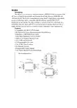
英文原文DescriptionThe at89s52 is a low-power, high-performance CMOS 8-bit microcomputer with 4K bytes of Flash Programmable and Erasable Read Only Memory (PEROM) and 128 bytes RAM. The device is manufactured using Atmel’s high density nonvolatile memory technology and is compatible with the industry standard MCS-51™ instruction set and pinout. The chip combines a versatile 8-bit CPU with Flash on a monolithic chip, the Atmel at89s52 is a powerful microcomputer which provides a highly flexible and cost effective solution to many embedded control applications.Features:• Compatible with MCS-51™ Products• 4K Bytes of In-System Reprogrammable Flash Memory• Endurance: 1,000 Write/Erase Cycles• Fully Static Operation: 0 Hz to 24 MHz• Three-Level Program Memory Lock• 128 x 8-Bit Internal RAM• 32 Programmable I/O Lines• Two 16-Bit Timer/Counters• Six Interrupt Sources• Programmable Serial Channel• Low Power Idle and Power Down ModesThe at89s52 provides the following standard features: 4K bytes of Flash, 128 bytes of RAM, 32 I/O lines, two 16-bit timer/counters, a five vector two-level interrupt architecture, a full duplex serial port, on-chip oscillator and clock circuitry. In addition, the at89s52 is designed with static logic for operation down to zero frequency and supports two software selectable power saving modes. The Idle Mode stops the CPU while allowing the RAM, timer/counters, serial port and interrupt system to continue functioning. The Power Down Mode saves the RAM contents but freezes the oscillator disabling all other chip functions until the next hardware reset. Pin Description:VCC Supply voltage.GND Ground.Port 0Port 0 is an 8-bit open drain bidirectional I/O port. As an output port each pin can sink eight TTL inputs. When is are written to port 0 pins, the pins can be used as high impedance inputs.Port 0 may also be configured to be the multiplexed loworder address/data bus during accesses to external program and data memory. In this mode P0 has internal pullups.Port 0 also receives the code bytes during Flash programming, and outputs theduring accesses to external memory. This pin is also the program pulse input (PROG) during Flash programming.In normal operation ALE is emitted at a constant rate of 1/6 the oscillator frequency, and may be used for external timing or clocking purposes. Note, however, that one ALE pulse is skipped during each access to external Data Memory.If desired, ALE operation can be disabled by setting bit 0 of SFR location 8EH. With the bit set, ALE is active only during a MOVX or MOVC instruction. Otherwise, the pin is weakly pulled high. Setting the ALE-disable bit has no effect if the microcontroller is in external execution mode.PSENProgram Store Enable is the read strobe to external program memory.When the at89s52 is executing code from external program memory, PSEN is activated twice each machine cycle, except that two PSEN activations are skipped during each access to external data memory.EA/VPPExternal Access Enable. EA must be strapped to GND in order to enable the device to fetch code from external program memory locations starting at 0000H up to FFFFH. Note, however, that if lock bit 1 is programmed, EA will be internally latched on reset.EA should be strapped to VCC for internal program executions.This pin also receives the 12-volt programming enable voltage(VPP) during Flash programming, for parts that require 12-volt VPP.XTAL1Input to the inverting oscillator amplifier and input to the internal clock operating circuit.XTAL2Output from the inverting oscillator amplifier.Oscillator CharacteristicsXTAL1 and XTAL2 are the input and output, respectively, of an inverting amplifier which can be configured for use as an on-chip oscillator, as shown in Figure 1. Either a quartz crystal or ceramic resonator may be used. To drive the device from an external clock source, XTAL2 should be left unconnected while XTAL1 is driven as shown in Figure 2. There are no requirements on the duty cycle of the external clock signal, since the input to the internal clocking circuitry is through adivide-by-two flip-flop, but minimum and maximum voltage high and low time specifications must be observed.Idle ModeIn idle mode, the CPU puts itself to sleep while all the onchip peripherals remain active. The mode is invoked by software. The content of the on-chip RAM and all the special functions registers remain unchanged during this mode. The idle mode can be terminated by any enabled interrupt or by a hardware reset.It should be noted that when idle is terminated by a hard ware reset, the device normally resumes program execution, from where it left off, up to two machine cycles before the internal reset algorithm takes control. On-chip hardware inhibits access toport pin or to external memory.RDY/BSY output signal. P3.4 is pulled low after ALE goes high during programming to indicate BUSY. P3.4 is pulled high again when programming is done to indicate READY.Program Verify: If lock bits LB1 and LB2 have not been programmed, the programmed code data can be read back via the address and data lines for verification. The lock bits cannot be verified directly. Verification of the lock bits is achieved by observing that their features are enabled.Chip Erase: T he entire Flash Programmable and Erasable Read Only Memory array is erased electrically by using the proper combination of control signals and by holding ALE/PROG low for 10 ms. The code array is written with all “1”s. The chip erase operation must be executed before the code memory can be re-programmed.Reading the Signature Bytes: The signature bytes are read by the same procedure as a normal verification of locations 030H, 031H, and 032H, except thatP3.6 and P3.7 must be pulled to a logic low. The values returned are as follows.(030H) = 1EH indicates manufactured by Atmel(031H) = 51H indicates 89C51(032H) = FFH indicates 12V programming(032H) = 05H indicates 5V programmingProgramming InterfaceEvery code byte in the Flash array can be written and the entire array can be erased by using the appropriate combination of control signals. The write operation cycle is selftimed and once initiated, will automatically time itself to completion.中文翻译描述at89s52是美国ATMEL公司生产的低电压,高性能CMOS8位单片机,片内含4Kbytes的快速可擦写的只读程序存储器(PEROM)和128 bytes 的随机存取数据存储器(RAM),器件采用ATMEL公司的高密度、非易失性存储技术生产,兼容标准MCS-51产品指令系统,片内置通用8位中央处理器(CPU)和flish存储单元,功能强大at89s52单片机可为您提供许多高性价比的应用场合,可灵活应用于各种控制领域。
NANCHANGUNIVERSITY毕业论文设计diploma project and thesis(2009—2011年)题目:基于单片机红外遥控开关设计英文题目:The Design of the Infrared-controller Based onSCM学院: 高等职业技术学院系别:信息工程系专业:应用电子技术班级:09级应用电子技术1学生姓名:胡会亮学号:8210909008指导老师: 梅光起讫日期:2011年11月1日-2012年5月15日二○一一年十二月摘要红外遥控技术的出现,不仅大大提高了劳动生产率,降低了成本,而且减轻了人们的劳动强度,改善了劳动条件。
红外线遥控器具有体积小、功耗低、功能强、成本低等特点从而成为了当今非常流行的一种控制方式红外遥控器是一种利用红外遥控系统来控制被控对象的系统.整个系统由数字电路和模拟电路两个部分组成。
发射部分包括键盘矩阵、编码调制、LED 红外发送器;接收部分包括LED红外光发射、解调、解码电路。
[1]通过对设计要求地认真分析和研究,拿出了几种可行方案,最终选定了一个最佳方案。
该方案是采用先进的单片机技术实现遥控的主要手段。
我们所设计的遥控器能控制5个电器的电源开关,并且可对一路电灯进行亮度的调节。
关键字:遥控电路,红外发射,红外接收,单片机AbstractInfrared remote control technology, not only greatly improved labor productivity, reduced costs, and reduce the people's labor intensity and improve the working conditions. Infrared remote control has a small size, low power consumption, functionality, and low cost in order to become a very popular present-day control.The infrared remote control is one kind of use infrared remote control system controls is controlled the object the department green overall system is composed by the digital circuit and the analogous circuit two parts. Launches partially including the keyboard matrix, the coded modulation, the LED infrared transmitter。
本科毕业论文(设计) 题目:基于STC51单片机的红外遥控风扇系统设计The design of infrared remote control fans system based矚慫润厲钐瘗睞枥庑赖。
on STC51 micro-controller毕业设计(论文)原创性声明和使用授权说明原创性声明本人郑重承诺:所呈交的毕业设计(论文),是我个人在指导教师的指导下进行的研究工作及取得的成果。
尽我所知,除文中特别加以标注和致谢的地方外,不包含其他人或组织已经发表或公布过的研究成果,也不包含我为获得及其它教育机构的学位或学历而使用过的材料。
对本研究提供过帮助和做出过贡献的个人或集体,均已在文中作了明确的说明并表示了谢意。
聞創沟燴鐺險爱氇谴净。
作者签名:日期:指导教师签名:日期:使用授权说明本人完全了解大学关于收集、保存、使用毕业设计(论文)的规定,即:按照学校要求提交毕业设计(论文)的印刷本和电子版本;学校有权保存毕业设计(论文)的印刷本和电子版,并提供目录检索与阅览服务;学校可以采用影印、缩印、数字化或其它复制手段保存论文;在不以赢利为目的前提下,学校可以公布论文的部分或全部内容。
残骛楼諍锩瀨濟溆塹籟。
作者签名:日期:学位论文原创性声明本人郑重声明:所呈交的论文是本人在导师的指导下独立进行研究所取得的研究成果。
除了文中特别加以标注引用的内容外,本论文不包含任何其他个人或集体已经发表或撰写的成果作品。
对本文的研究做出重要贡献的个人和集体,均已在文中以明确方式标明。
本人完全意识到本声明的法律后果由本人承担。
酽锕极額閉镇桧猪訣锥。
作者签名:日期:年月日学位论文版权使用授权书本学位论文作者完全了解学校有关保留、使用学位论文的规定,同意学校保留并向国家有关部门或机构送交论文的复印件和电子版,允许论文被查阅和借阅。
本人授权大学可以将本学位论文的全部或部分内容编入有关数据库进行检索,可以采用影印、缩印或扫描等复制手段保存和汇编本学位论文。
外文原文Based on infrared alarm technology security systems1 the introduction1.1 the research significance of this topic research situation at home and abroad .With the development of society and science and technology unceasing development, people's living standards been improved greatly, and to the private property protection means in the unceasing enhancement, the intelligent facilities for anti-theft puts forward new requirements. This design is to meet the need of modern residentialanti-theft designed family electronic alarm system. It in previous devices based on improved greatly, because use the single-chip processor signal, not only can used for single residential area, also can be used in a large-scale residential security systems. It's the job of the performance is good, do not appear to reportand misstatement phenomenon, safe and reliable.In our country, the present market condition alarm basically has triggered alarm system pressure switch electron and alarm system and pressure shading triggered alarm system, etc. Various kinds of alarm, but this several common alarm there are some shortcomings. This system USES a human pyroelectric infrared sensor in the human body detector in the flied, passive pyroelectric infrared detectors because of its low cost, easy fabrication, low cost, installation is more convenient, anti-theft performance is stable and high sensitivity, safe and reliable, has attracted broad family characteristics such as popular with thecustomers. And alarms installation concealment, not easily by rogue found.1.2 infrared alarm technology introduction1.2.1 nature objects of the infrared radiationThe nature of any object, as long as the temperature above absolute zero (273 ℃), constantly outward issued infrared radiation, and travel at the speed of light energy. Object radiate outward infrared radiation of energy and the object of temperature and infrared radiant wavelength. Assuming objects launching infrared radiation of peak wavelength for a few, its temperature for T, the radiation energy equals infrared radiation of peak wavelength gerben and object product temperature T. This product is a constant, namely:The higher the temperature of the objects, emit infrared radiation of the smaller peak wavelength, send out infrared radiation energy is bigger also.1.2.2.pyroelectric effectPassive infrared detector also called pyroelectric infrared detector, its main working principle is pyroelectric effect.Pyroelectric effect means if make some strong dielectric material (such as qin batio3, qin wrong acid lead P (zT), etc.) of the surface temperature changes, then with the temperature rise or fall, material surface occurs polarization, namely on the surface of the charge will beproduced change, and material surface charge lost balance and eventually charge will change withvoltage or current form output.1.2.3 pyroelectric infrared sensor basic structurePyroelectric infrared sensors from sensor detection yuan, interference filters and mosfet verifier three parts. According to the number of detecting yuan to points, pyroelectric infrared sensors have unit, double yuanhe four yuan to wait for a few kinds, for human detection of infrared sensor adopts double yuan or four yuantype structure. According to pyroelectric infrared sensor utility cent, have the following kinds: used for measuring temperature sensor, it'sthe job of the wavelength of (1-20) nano, Used for flame detection sensor, it's the job of the wavelength for0.435 + / - 0.15 nano, For human detection sensor, it's the jobof the wavelength of 7 to 15 feet. Figure 1.2 is a double detection yuan pyroelectric infrared sensor structure schematic drawing. The sensorwill two opposite polarity, special1.2.4 pyroelectric infrared detector basic principlePyroelectric infrared sensor by receiving mobile human radiation that certain wavelengths of infrared radiation, can be transformed into and human body movement speed and distance, the direction of low-frequency signals about. When pyroelectric infrared sensor by ir radiation sources of radiation, its internal sensitive materials temperatures will rise, polarization intensity is abate, surface charge reduce, usually will release this part of the charge called pyroelectric charge. Because of pyroelectric charge how many can reflect material changes of temperature, so by pyroelectric charge by circuit transformed into the output voltage can also reflect material changes in temperature, thus detect ir radiation energy changes.2 hardware system design2.1 infrared anti-theft alarm system hardware designBecause this design focuses on family guard against theft, real-time monitoring of a narrower range, so this design by simply using a passive infrared detector is enough. Therefore, infrared intelligentanti-theft alarm system, and the specific design requirements for:(1)completes to high sensitive infrared sensor design, make its can warning of what happened real-time and accurate detection.(2) automatic alarm (automatic dial-up alarm audible and visual alarm). We design the system must have the following function module:1.passive infrared detector,2.sound-light alarm,3.telephone automatic dial-up function;4.continued uninterrupted power supply,According to the system to complete functions, we adopt single chip microcomputer as the core of the system unit, electronic detection, intelligent control and telephone tong。
Infrared Remote Control SystemAbstractRed outside data correspondence the technique be currently within the scope of world drive extensive usage of a kind of wireless conjunction technique,drive numerous hardware and software platform support. Red outside the transceiver product have cost low, small scaled turn, the baud rate be quick, point to point SSL, not by the electromagnetic interference etc.characteristics, can realization information at dissimilarity of the product fast, convenience, safely exchange and transmission, at short distance wireless deliver aspect to own very obvious of advantage.Along with red outside the data deliver a technique more and more mature, the cost descend, red outside the transceiver necessarily will get at the short distance communication realm more extensive of application.The purpose that design this system is transmit customer’s operation information with infrared rays for transmit media, then demodulate original signal with receive circuit. It use coding chip to modulate signal and use decoding chip to demodulate signal. The coding chip is PT2262 and decoding chip is PT2272. Both chips are made in Taiwan. Main work principle is that we provide to input the information for the PT2262 with coding keyboard. The input information was coded by PT2262 and loading to high frequent load wave whose frequent is 38 kHz, then modulate infrared transmit dioxide and radiate space outside when it attain enough power. The receive circuit receive the signal and demodulate original information. The original signal was decoded by PT2272, so as to drive some circuit to accomplish customer’s operation demand.Keywords:Infrared;Code;Decoding;LM386;Redout-side transceiver1 Introduction1.1 research the background and significanceInfrared Data Communication Technology is the world wide use of a wireless connection technology, by the many hardware and software platforms supported. Is a data through electrical pulses and infrared optical pulse switch between the wireless data transceiver technology.Infrared transceiver products with low cost, small, fast transmission rate, the point-to-point transmission security, not subject to electromagnetic interference and other characteristics that can be achieved between the different products, rapid, convenient and safe exchange and transmission, In short distance wireless transmission have a very distinct advantage.Infrared transceiver products in the portable product of a great role. At present, the world's 150 million piece of equipment used infrared technology in electronic products and industrial equipment. medical equipment and other fields widely used. For example, 95% of the notebook computers on the installation of infrared transceiver interface the majority of the cell phone is also the allocation of infrared transceiver interface. With the exchange of quantitative data, infrared data communications will enable cell phone data transmission more convenient. With infrared data transmission technology matures, perfect, low costs, Infrared Transceiver in short distance communications will be more widely applied.This chapter first describes the infrared transceiver IC design issues to the background and significance. then briefed the infrared data communications technology features and applications, and infrared transceiver product characteristics, domestic and international situation and development trend of the last under infrared remote transceiver system in practical application to establish a task of design orientation.1.2 Infrared Remote Control Transceiver SystemInfrared remote control system is divided into single-channel and multi-channel remote control. Only a command signal transmission channel, called single-channel remote control system; with more than two instructions signal transmission channel known as a multi-channel remote control system. Relatively simple single-channel remote control, in general, only a launcher directive Key receivers and only one circuit implementation. While in the receiving circuit to add more stable memory circuits that can be activated commands to launch a number of key, so that the receiver circuit multistate memory circuit repeatedly to change the state, to realize many of the functional control, But such a state of change is the order. If we are to achieve an arbitrary control, resort to the use of multi-channel remote control system. Multi-channel remote control can be realized by the object of arbitrary multi-function remote control. As for the choice of several routes and what control methods, according to the actual situation (such as object, operational requirements and cost accounting, etc.) to decide. General infrared remote transceiver system by infrared remote control transmitter signal coding, infrared remote control signal receivers and decoders (or decoder chip MCU) and the external circuit consisting of three parts. Signal transmitter remote control code used to generate pulses of infrared emission-driven output infrared remote control signal, receiver completion of the remote control signal amplification and detection, plastic and demodulation encoding pulse. Infrared remote control coded pulse is going to obtain a continuous serial binary code, and for most of the infrared transceiver system, This serial code as micro-controller of the remote control input signals from the internal CPU completion of the remote control instruction decoder, on the other infrared remote control transceivers, the designers of electronic products, The internal micro-controller of the remote control decoder directive is not accessible.Therefore, people are using infrared encoder / decoder chip and micro-controller developed various generic infrared remote transceiver system, In various equipment infrared signals between the transceiver.Remote transceiver system generally transmitters and receivers is composed of two parts. Launchers from the general direction keys, coded instructions circuit modulation circuit, driving circuit, firing circuit of several parts. When pressed a key, the directive coding circuit, in the corresponding instructions encoded signal, the encoder signal to the carrier modulation, Driven by the power amplifier circuit after circuit fired from the field after firing instructions coded modulation signals. General receiver by the receiving circuit, the amplifier circuit, demodulation circuits, instruction decoder circuit, driving circuit, circuit implementation of several parts. Receiving Circuit will launch vehicles have been coded modulation signal receiving instructions from, and to enlarge evacuation demodulation circuit. Demodulation circuit will have the coding modulation signal demodulation, namely, reduction of signal coding. The instruction decoder to the encoder signal decoding, Driven by the final circuit to drive the implementation of various instructions circuit to control the operation.1.3 infrared remote control transceiver product profiles 1.3.1 infrared remote control transceiver product structure and typeCurrently infrared transceiver in accordance with the mode of transmission rate and can be divided into four categories : Serial mode, the highest rate of 115.2 Kbps; medium-speed model : the highest rate of 0.567 Mbps and 1.152Mbps; High-speed mode : The maximum rate of 16 Mbps.Also according to the size chip power consumption can be divided into low-power consumption and standard two categories, low-power type normally used 3 V power supply, transmission distance closer to about 0 - 30cm, which is commonly used standard 5V power supply, transmission distance away at least 1mabove.1.3.2 infrared remote control transmitters of the status quo at home and abroadInfrared communication technology in the development stage and there are several infrared communication standards, between different standards for infrared equipment can not infrared communication. To have all the infrared equipment to interoperability in 1993 by more than 20 large manufacturers initiated the establishment of an Infrared Data Association (IRDA) unified the infrared communication standards , which is currently widely used in infrared data communication protocols and standards, also known as the IRDA standard.Since 1993 IRDA since the establishment of the Infrared Data Association members have developed to more than 150. IRDA standards of the industry has been widely recognized and supported. Has been developed with the infrared communications equipment have been as many as 100 species. IR module, installed capacity has reached 150 million sets. Although there is also a short distance wireless Bluetooth technology, But in infrared communication technology low cost and broad compatibility advantages, Infrared data communication in the future will still be a very long time inherent short-range wireless data communications fields play an important role.1.3.3 Infrared Transceiver product development trendIn various infrared transceiver products, although the transmission rate, transmission distance and other characteristics, But infrared transceiver products has been towards improving the transmission rate, increase the transmission distance and lower power consumption, expanding launch reception angle of development. In particular, as the technology development and maturity, the means of transmission is moving in the direction of point-to-multipoint. Therefore infrared remote control transceiver products have broader prospects for development.2 Infrared communication of knowledge2.1 infrared ray foundation knowledge2.1.1 infrared outlinedInfrared is actually a kind of electromagnetic wave. From the analysis of various natural component of the electromagnetic wave reflected spectrum is :-ray, x-ray, ultraviolet, visible, infrared, microwave and radio wave. From the viewpoint of form, and they did not seem to, but if the wavelength in descending order, and we will find him all the only visible light spectrum of the entire 0.38 μm - 0.76μm so long little area, and adjacent to the visible light and infrared (including the far infrared, mid-infrared and near infrared foreign) accounts for the spectrum of 0.76 μm - 1000μm of a major. Which micron wavelength range also includes UV, visible, near infrared, mid-infrared and far-infrared, microwave.From the above analysis shows that infrared is a very rich spectrum resources, it currently has in production, life, military, medical, and other aspects have been widely used, such as infrared heating, medical infrared, infrared communication, infrared camera, infrared remote control, and so on. Infrared remote control is the many applications of infrared part of the current household appliances widely used in TV remote control, VCR remote control, VCD remote control, high-fidelity audio remote control, are used infra-red remote control, It allows the control of these appliances have become very easy.2.1.2 infrared propertiesInfrared lies between visible light and microwave a wave, it is with certain clinical characteristics of the wave. In the near-infrared, visible light and its adjacent, it is visible in certain characteristics, such as straight-line transmission, reflection, refraction, scattering, diffraction, can be certainobjects and can be absorbed through the lens of their focusing. In the far-infrared region, owing to its neighboring microwave, it has some characteristics of microwave, If a strong penetrating power and can run through some opaque substances. Since in any object, natural profession, regardless of whether its own luminescence (referring to visible light), as long as the temperature is above absolute zero (-273 °C), moment will be kept around to infrared radiation. Only higher temperature of objects strong infrared radiation, low-temperature objects infrared radiation weaker. Therefore infrared feature is the greatest common in nature, it is called thermal radiation called thermal radiation. Infrared cameras, infrared night market pyroelectric infrared detectors and some other missiles aiming at is the use of this characteristic of infrared work.Infrared and visible light compared to another characteristic of a variety of colors. As the longest wavelength of visible light is a wavelength of the shortest times (780 nm-380 nm), So is called an octave. And infrared wavelength is the longest shortest wavelength of a times, and the longest wavelength infrared is the shortest wavelength of 10 times, that is, 10 octave. Therefore, if visible light can be expressed as seven colors, infrared may performance 70 colors, showing the rich colors. Infrared smoke through the good performance, which is also one of its features.Because not visible to the infrared, it has little effect on the environment. By the wave infrared rays than the long wavelength radio waves, infrared remote control will not affect the nearby radio equipment. Another wavelength of less than 1.5μm near infrared light, transparent atmosphere in t he visible light transmission characteristics much better than, because it close to the visible edge of the red light, linear transmission, reflection, refraction and absorption material and the physical characteristics very similar to visible light. Therefore, it can be used with similar visible focusing lens and other opticaldevices. Because infrared remote control is not as remote as the radio through the barrier to control the object's ability to control, so in the design of household appliances infra-red remote control, wireless remote control as unnecessary, each set (transmitters and receivers) have different frequency or remote coding (Otherwise, wall will control or interference with neighbors household appliances), all similar products in the infrared remote control, The same can control the frequency or coding, and no remote control signal "drop." This universal infrared remote control provides a great convenience. Infrared to visible light, is very subtle and confidentiality, therefore, the security, Alert and other security devices have been widely used. Infrared remote control is simple in structure and easy, low-cost, anti-interference capability, high reliability are a number of advantages, is a close-up remote control, especially in indoor remote control optimized manner.2.1.3 infrared diode characteristicsInfrared is not visible, people here are not aware of. Electronic technology is used infrared light emitting diode (also known as the IR emission diode) to generate infrared. Infrared remote control transceiver is using near-infrared transmission control instructions 0.76μm wavelength of ~ 1. 5μm. Near-infrared remote control as a light source, because there infrared light emitting diodes and infrared receiving device (photodiode. Transistor and PV) and the luminescence peak wavelength of light by the general 0.8μm ~ 0. 94μm. in the near-infrared band, both of the spectrum is the coincidence to a good match, access to higher transmission efficiency and higher reliability. Commonly used infrared diode, and its shape is similar LED light emitting diodes, Its basic circuit shown in figure 2 -2. The triode plans for the switch, when the base added a driving signal, Transistor saturated conduction infrared LED D is also Wizard Link, issued infrar ed (near infrared about 0.93 μm). D.The pressure drop of about 1.4 V and the current general for 10-20mA. To adapt to the working voltage of the D loop resistance often as a series of infrared diode current limit resistance.When the circuit diagram of the infrared emission control corresponding to the controlled device, the control of the distance and D is proportional to the transmitting power. In order to increase the distance of infrared control, infrared diode D should work on the pulse state that work is the lifeblood of current. Because pulse light (optical modulation) the effective transmission distance and pulse is proportional to the peak current, only maximize peak current Ip, will increase the infrared distance. Ip increase is a way to reduce th e pulse duty cycle, that is compressed pulse width τ some TV infrared remote control, its infrared luminescence of the pulse duty cycle of about 1/4-1/3; Some electrical products infrared remote control, its duty cycle of 1 / 10. Decreasing pulse duty cycle also enable low-power infrared LED distance of the greatly increased. Common infrared light emitting diodes, power is divided into small power (1 mW - 10mW). Chinese power (20mW - 50mW) and power (50mW - 100mW more) three categories. Use different power infrared LED, the allocation should be driven by the corresponding power control. Figure 2 -2 by the reflected infrared light-emitting diodes to make produce optical modulation, Drivers only need to add the control of a certain frequency pulse voltage.Infrared transmitter and receiver in the way the two kinds of straight, and the second is reflective. Luminescence pointed straight pipe and tube receiver placed in a relatively controlled and fired on the two ends, a certain distance away from the middle; Reflective means luminescent tube and pipe parallel with the receiving peacetime, without always receiving tube light, luminescence only in possession of the infrared light reflected fromencountered, the receiving tube received from the reflected infrared before work.2.2 infrared communication basic tenets2.2.1 infrared communication PrincipleCommunication is the use of infrared wavelength of 900 nm-infrared waves from 1000 to serve as an information carrier, through infrared technology between the two close communication and confidentiality of information transmitted. Infrared communication system structure include : part launcher, channel, the receiver part.Launcher source letter issued after the binary signal from the high-frequency modulated infrared LED sent, receiving device regard the reception of high-frequency signals from the infrared receiver tube after receiving further demodulation photoelectric conversion of the original information of a mass communication lose way. Afterwards the former Information received after receiving part of the drive circuit connected to the expected completion of the various functions. To which the modulation coding style pulse width modulation (by changing the pulse width modulated signal PWM) and pulse modulation time (through change the pulse train interval time between the modulation signal PPM) two.2.2.2 infrared communication system elements(1) Launches : Currently there is a infrared wireless digital communications system sources of information including voice, data, images. Its methods of work for the launch of the receiver can be divided into different layout LOS way (Light-of-Sight , intracardiac way), diffuse (diffuse) mode. LOS way directional, it has good channel characteristics such advantages, but the existence of a "shadow" effect. difficult to achieve roaming function. Roaming means the main features of non-directional, and easy to implementroaming function, but its channel quality is better sometimes LOS way. Transmission of signals required for a few of (the sampling was quantified), the general need for baseband modulation, transmission, modulation, sometimes signal source coding, the above-driven signals from photoelectric converter complete optical signal transmission. Infrared wireless digital communications system and its scope of work-for-fired power distribution, the quality of the communication. While using various methods to improve optical transmitter power, the other using spatial diversity, holographic films and so on so diffuse light for the launch of space optical power evenly distributed.(2) Channel : infrared wireless digital communication channel refers to the transmitters and receivers in the space between. Due to natural light and artificial light sources such as light signals in the context of intervention, and the source - Electrical Equipment, The optical noise and disturbances, infrared wireless digital communications in some occasions, poor quality, At this point needed to channel coding. Infrared wireless communication system, the optical signal reflection, light scattering and background noise and interference effects, Infrared wireless digital channel presence multi-path interference and noise, This is to improve the quality and access for high-speed applications should be addressed. Infrared wireless digital communication channel often used by the major optical components, optical filter, condenser, their role is : plastic, filter, depending on the field transformation, the band division, the lens can be used as launch-ray focusing, the use of optical filters filter out stray light, the use of optical lenses to expand the field of view receiver, able to make use of optical components for the link frequency division multiplexing, etc.. Infrared wireless communication channel optical noise : the natural noise (sunlight) and anthropogenic interference (fluorescent lighting). can be modulated by the transmission technology such as filters and adding to be addressed.(3) receivers : Channel optical signal from the optical receiver partially photoelectric conversion, In order to remove noise and inter-symbol interference and other functions. Infrared wireless digital communications system receiver include optical receiver parts and follow-up sampling, filtering, judgment, quantity, balanced and decoding part. Infrared wireless optical receiver often used amplifier, and called for large-bandwidth, high gain, low noise and low noise, frequency response and channel impulse response matched. To be suppressed by low-frequency noise and human disturbance needs a band-pass filter. To obtain large optical receiver scope and instantaneous field of view, often using spherical optical lens.2.2.3 infrared communications featureWireless communications are a lot of ways, some using infrared communication with the following characteristics :• The high frequency, wave length, and fired the energy concentrated space propagation attenuation coefficient can ensure the effective signal transmission;• infrared is the invisible light, strong confidential ity and use it as an information carrier. device when there is no visual pollution, it does no harm to the human body;• dissemination without limitation, and there is no question of frequency interference with radio-wave pattern, not on the spectrum resources to the relevant authorities for the application and registration, easy to implement;• has a good point, when the transmission equipment and infrared receiver ports line up straight, deviation of not more than about 15 degrees when infrared devices running the best effect;• through infrared or not bypassed and objects, data transmission, optical path can not be blocked;• currently produce and receive infrared signals in the technology is relatively mature, components small size, low cost production of simple, easy to produce and modulation advantages.2.3 infrared communication code based on the knowledgeUsually, infrared remote control transmitters will signal (pulse binary code) modulation at 38 KHz carrier, After buffer amplified sent to the infrared light-emitting diodes, infrared signals into firing away. Pulse binary code in a variety of formats. One of the most commonly used code is PWM (pulse width modulation code) and the PPM code (Pulse Code Modulation). The former said in a pulse width, pulse indicated 0. The latter pulse width, but the width of code-not the same, the codes represent a bit - and the digits represent narrow 0.Remote coding pulse signal (PPM code as an example) are usually guided by the code, the system code, the anti-code system, a feature code, functional anti-code signal components. Guide the code name for the initial code, by the width of 9 ms and the margin width of 4.5 ms to the low-level components (different remote control systems in the low-level high width of a certain distinction), remote coding used to mark the beginning of pulsed signals. System identification code is also called code, which used to indicate the type of remote control system, in order to distinguish other remote-control system, prevent the remote control system malfunction. Functional code is also called scripts, which represents the corresponding control functions, Receiver of the micro-controller functions under the numerical code to complete the various functions operating. Anti-code system and function codes are anti-system code and the functional code against code Anti-code can be joined to the receiver synchronization transmission process leads to errors. In order to improve performance and reduce interference power consumption, The remote control will be coded pulse frequency of 38 KHz (for the cycle of 26.3 ms) of the carrier signal pulse reshuffle system (PAM), and then sentto the buffer amplified infrared LED, the remote control signal transmitter away.Address code and data codes are composed of different pulse width expressed that the two narrow pulse "0"; 2 pulse width "1"; a narrow pulse width and pulse expressed an "F" is the code addresses "vacant."Is the first part of a group a group of code, each code synchronization between separated. The plan is to enlarge the second half of a group code : a code from 12 AD (the address code plus data code For example, eight address code plus four data code), each with two AD-Pulse's : Pulse said the two "0"; 2 pulse width "1"; a narrow pulse width and pulse expressed an "F" is the code addresses "vacant."Realize fired at each fired at least four groups code, PT2272 only twice in a row to detect the same address code plus data code data will be the code "1" is driven The data should be output to drive margin and VT terminal for synchronous serial.红外遥控系统摘要红外数据通信技术是目前在世界范围内被广泛使用的一种无线连接技术,被众多的硬件和软件平台所支持。
JSJ-1302计算机信息工程学院2013 届毕业设计(论文)外文阅读与翻译毕业设计题目基于STC单片机的红外遥控开关系统的设计外文翻译题目Decoding Infraed Remote Controls Using a PIC16C5X Microcontroller专业计算机信息科学与技术班级姓名学号指导教师职称介绍:家用电子工业已经应用红外遥控器控制电视机,录像机和有线电视很多年了。
同样的技术最近开始应用于工业应用以替代小键盘。
可以通过PIC16C5X译解大多数的红外信号。
这份说明书是描述如何破解的。
唯一用来译解IR信号的强制性硬件是红外接收仪。
它的两种类型的用法在这里都有说明。
两种模块类型都经常被用于家用电子工业。
第一种类型响应的已调制的红外信号大概为40KHz。
第二种响应未调制的红外脉冲并且有受限范围。
每种类型的硬件成本都不高于2美元。
此处描述了三种PIC16C5X应用程序,说明了如何用它们来创建一个算法使其能够破译任何遥控信号。
每种PIC16C5X应用程序表示在映射出一个预先存在的红外格式的一个步骤。
最终的应用程序是一个用来完全实现的示例的红外信号解码和解调的一种Teknika电视遥控器。
三个层次的红外线信号典型的红外信号遥控器有三层。
用于这些层的名字没有被标准化。
在这个应用程序中注意他们被称为“红外、调制和串行数据。
红外层是种发射方式。
红外线是一种因为波长太长以至于看不到的光。
虽然你不能看到红外光束,但它是光的一种形式,所以如果你不能看到目标设备,你就不能用红外信号控制它。
控制绕过拐角,通过不透明的材料、RF,通常使用超高频信号。
虽然这个应用程序注没有进一步提到RF,这里介绍的许多东西都是可以用作一个射频传输介质。
这个频率层爆出的红外信号通常是在频率调制32.75千赫和56.8千赫之间。
这样做是为了减少环境光的影响。
虽然考虑到这一层,但还是可选的。
如果不调整红外格式的输出,发送脉冲与未调整的红外线则相反。
这样做是为了延长电池寿命和远程控制减少成本的遥控装置。
串行数据层的信息包含一个命令。
这是典型的编码在长度的红外脉冲或长度的差距红外脉冲。
一个长缺口或突变被诠释为一个“1”,一个短间隙或突变被解释为“0”。
硬件信息在示意图显示了一个工具,可以帮助解调红外接收器的代码。
图示由PIC16C57连接到两种可用的红外接收器。
一个接收器是为非调制信号,另一个用于调制信号。
调制接收器都可以从夏普和Lite,零件编号和lt - 1060 GP1U521Y分别解调。
这个非调制类型可以从质量技术QSE157QT零件号码。
PIC16C57的选择并不表示这些处理操作需要解码。
典型的红外接收器的代码可以放入不到一半的可用PIC16C54 ROM空间中,并使用四个内存位置。
选择一个PIC16C57是由于需要存储大量的信号长度为以后阅读方便。
PIC16C57含有一个陶瓷谐振器时钟。
它会给足够的频率准确度来确定脉冲和间隙长度。
一个RC网络通常不会有足够的精度。
PIC16C57含有一个按钮用于重置,和四个跳投是提供用于控制应用程序启动。
这两个数字显示是多路复用,驱动时通过Q1和Q2实现。
三个八进制开关最为输入来控制选项显示,哪些文件注册。
整个电路得出其权力从9v,200米墙安装供应。
U1调节9v降到5v的PIC16C57和相关电路。
软件开发援助描述这个应用程序使用四种不同的固件文件IRMAIN。
ASM控制三个应用程序文件。
第一个文件是衡量ASM红外部件,以及内存,并允许传播information。
IR6121.ASM 将NEC6121红外格式代码转码到在LED显示屏显示。
最后一个文件,TEC-NICKA. ASM 显示了最终的固件解码红外格式。
固件上包括三个应用程序,其将帮助设计一个红外控制系统。
IRMAIN. ASM读取跳转1、2和程序流重置。
如果没有跳转至2将直接程序流来衡量ASM。
如果跳转至2只会直接对IR6121.ASM产生程序流。
跳转在这两个1和2将直接程序流向TEKNIKA.ASM跳转至3和4。
这三个应用程序是最基本的和最有用的。
这个程序将存储红外突发和间隙长度到内存中,允许的测量ments播放,通过两个数字显示其差距。
它允许OPTION控制寄存器也通过SW1。
SW1的设置是直接读入OPTION寄存器的频值TMR0。
如果在程序操作过程中SW1改变了,PIC16C57复位。
“连字符”启动后将被显示在左边的数字空间,直到红外线输入,黑暗的图示表明准备接收红外线信号作为一个红外信号出现时,长度的爆发的红外和长度的差距破裂存储在连续文件位置,直到PIC16C57所有的内存文件都充满。
如果一个跳线已经在1,程序扔掉的前32脉冲间隙长度,开始储存脉冲和间隙长度的第33脉冲长度。
这允许很长的解码格式。
当所有四页的内存文件充满了脉冲和间隙长度,数量和小数点表现。
小数点表明,单位是donereading。
这个数字是一个间隙或脉冲长度。
SW2和SW3控制脉冲或显示间隙长度的时间序列。
这些在SW3下的八进制是更有效的。
编写一个算法来解码红外遥控器的说明1.设计一个系统,它使用一个红外遥控器,第一步是选择一个遥控器。
拥有自己的设计或现成的,调制或未调制的是主要的技术决策。
2.一旦遥控器已经被选择或设计,其调制频率,如果有的话,必须确定。
这用于接收红外信号来控制选择什么样的硬件。
3.下一步是确定的时间数据的基础上,也就是说,以脉冲和差距是短或长的PIC16C57时钟参数。
选择开关SW1,以获得最佳的长脉冲和差距计数TMR0。
这个定义的作用是预选分频器。
4.第四步,定义,在格式上定义了一个‘1 '的格式和一个‘0’格式。
这可能是差距计数,脉冲计数,或两者的结合。
5.第五步,确定制成的全长的命令。
这使得确定按钮是否被按下,或者如果与前面相同类型的一个新的命令被发出。
6.第六步需要编写代码。
代码将解决差距和脉冲长度和命令的长度成比特和字节。
每个按钮在远程将解码一个独特的连续位。
7.第七步,也是最后一步将这些收到的代码,将它们转换成数字或命令按钮,使用一个查找表。
步骤1:选择一个远程控制取决于您的应用程序,您可能会选择选择一个遥控器,拥有自己的设计或现成的。
通常他们在他们的小4比特微控制器上设定为一个串行格式。
一些公司如通用仪器COM 命令,其他如NEC出售主要成分,可以定制由外部二极管到不会干扰其他应用程序。
也可以计划一个PIC16C57来生成一个信号,可以发送给一个红外LED传输。
另一种方法是使用一个可编程的远程控制来生成任意数量的红外格式,并使用它们对现成的目标设备进行控制。
步骤2:确定调制频率对于这一点,下一个步骤的MEASURE.ASM程序将使用。
展开,取出,使用非调制的接收器和PIC16C57运行MEASURE.ASM应用程序的。
选择1选项selector.Press一个按钮,直到小数点结束。
通过记忆的脉冲持续时间使用的跳线开关PIC16C57将存储在内存中。
如果所有的输出(第一个除外)均低于40小时,红外的格式是一个调制的。
如果一半或更多的值显示为0FFh的,则是远程非调制。
步骤3:确定时基如果遥控器的调制、解调红外接收器切换到的选项的选择仍处于1,再次按下遥控器上的一个按钮,直到小数点来。
该系列记忆的脉冲持续时间,现在可能会包括FFH值很多。
如果是这样,移动选项的选择,直到值7H1FH范围。
期权选择的最佳选项除数,TMR0寄存器值。
要优化覆盖范围和可靠性,几个解调接收器,可尝试。
这些都可以从夏普或精简版上。
目前所使用的调制频率是32.75千赫,35.0千赫,36.0千赫,36.7kHz 电源,38千赫,39千赫,40千赫,41.7千赫,48千赫,56.8千赫。
最常见的是一轮40千赫。
会给你的遥控器的最佳匹配最长范围和最一致的结果。
步骤4:解码1和0下一个步骤是绘制出的特征的脉冲代表1和0的间隙长度。
按相同的遥控器上的按钮,写下一系列数字阅读由PIC16C57运行措施,ASM程序。
每个奇数编号的条目是一个来自遥控器的红外突发的持续时间。
每个偶数编号的输入项的红外脉冲串之间的间隙的持续时间。
这些差距和阵阵的长度定义的和为零。
它们的顺序将取决于哪个按钮被按下。
一旦特征长度已经发现了一个和一个零,然后创建一个算法,用一个计数器来翻译成“和”0“的长度。
步骤5:找到命令的长度再次按同样的按钮。
命令持续时间也可以找到。
这是必要的,以确定一个按钮被压低或一个新的相同类型的命令已经发出了。
大多数遥控器重复命令时,只要按住按钮,重复分离一段时间,通常在一个甚至数0 ffh过渡。
如果没有长甚至容易的计数可以发现,认为某些COM命令可以长于64转换。
延迟计数的选项是这个原因。
插入跳线1和小节。
ASM将开始储存后的第32届过渡的过渡时间。
步骤6:翻译长度成碎片一旦特征长度的1和0中被发现并已被发现的典型的命令的长度,一个程序可以被写入解码这些长度“和”0“,并将其显示两位数字的显示。
也可以创建一个HOLD标志,这将是真实的,只要按钮被按住。
一般1/8秒之间的命令,指示一个新的命令。
使用这个值来保持时间和命令之间的时间超时。
IR6121.ASM是一个程序,它的NEC6121格式转换的间隙长度的4个字节构成的每个命令的信息的一个示例。
步骤7:创建一个按钮代码交叉参考表TEKNIKA.ASM实现了一个查找表来把代码转换接收到的实际按下按钮。
计数器最高时,可以按下按钮,然后抬起头,比对收到的代码。
如果不匹配,计数器递减,直到找到下一个匹配。
当发现时,从计数器读出有按钮被按下的数量。
同时也要注意到,在这个级别上的一些格式做更多的检查,比如具有一个地址,一个补充的代码检查下面的代码本身。
来自解码中的步骤的的结果是:如果按下遥控器一个按钮,按钮的号码出现在PIC16C57文件位置。
一个命令如通道或下降通道将会出现两个组标志,指示命令,以表明它是持有活跃的。
从这一点上应用程序可以访问这些标志和文件做出适当反应。
注意下面的详细代码在PICmicro MCUs保护特性。
•Microchip的满足Microchip数据手册中包含的规格。
•Microchip的认为其Microchip系列是当今市场上同类最安全的产品之一,当预期的方式,在正常条件下使用。
•有用来破坏代码保护功能的恶意,甚至是非法的方法。
所有这些方法,就我们所知,需要的方式数据表中包含的操作规范来使用Microchip的微控制器。
这样做的人可能从事窃取知识产权。
•Microchip愿与客户的工作谁关心他们的代码的完整性。
•Microchip或任何其他半导体厂商可以保证自己的代码的安全性。
代码保护并不意味着我们保证产品是“牢不可破”的。