多路选择器(MUX)功能实现Verilog HDL源代码
- 格式:pdf
- 大小:166.18 KB
- 文档页数:3
实验三 4位2选1多路选择器的设计与实现一.实验目的1.使用ISE软件设计并仿真;2.学会程序下载。
二.实验内容使用ISE软件进行4位2选1多路选择器的设计与实现。
三.实验步骤1. 编写文本文件并编译2. 软件仿真3. 进行硬件配置四.实验原理1. ISE软件是一个支持数字系统设计的开发平台。
2. 用ISE软件进行设计开发时基于相应器件型号的。
注意:软件设计时选择的器件型号是与实际下载板上的器件型号相同。
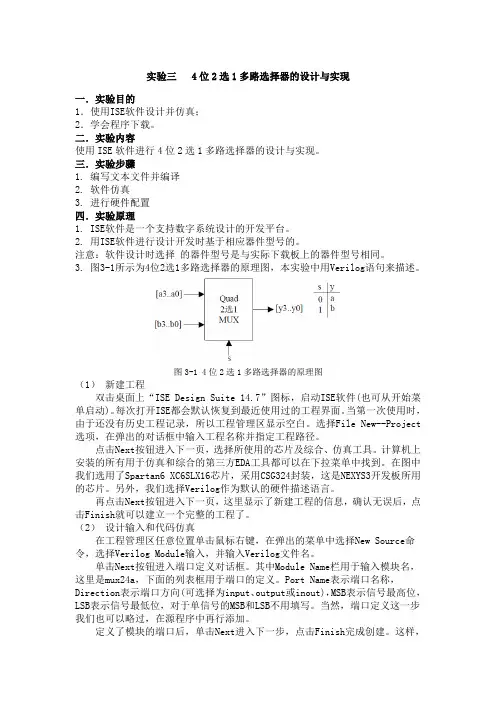
3. 图3-1所示为4位2选1多路选择器的原理图,本实验中用Verilog语句来描述。
图3-1 4位2选1多路选择器的原理图(1)新建工程双击桌面上“ISE Design Suite 14.7”图标,启动ISE软件(也可从开始菜单启动)。
每次打开ISE都会默认恢复到最近使用过的工程界面。
当第一次使用时,由于还没有历史工程记录,所以工程管理区显示空白。
选择File New--Project 选项,在弹出的对话框中输入工程名称并指定工程路径。
点击Next按钮进入下一页,选择所使用的芯片及综合、仿真工具。
计算机上安装的所有用于仿真和综合的第三方EDA工具都可以在下拉菜单中找到。
在图中我们选用了Spartan6 XC6SLX16芯片,采用CSG324封装,这是NEXYS3开发板所用的芯片。
另外,我们选择Verilog作为默认的硬件描述语言。
再点击Next按钮进入下一页,这里显示了新建工程的信息,确认无误后,点击Finish就可以建立一个完整的工程了。
(2)设计输入和代码仿真在工程管理区任意位置单击鼠标右键,在弹出的菜单中选择New Source命令,选择Verilog Module输入,并输入Verilog文件名。
单击Next按钮进入端口定义对话框。
其中Module Name栏用于输入模块名,这里是mux24a,下面的列表框用于端口的定义。
Port Name表示端口名称,Direction表示端口方向(可选择为input、output或inout),MSB表示信号最高位,LSB表示信号最低位,对于单信号的MSB和LSB不用填写。
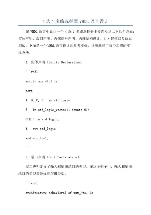
4选1多路选择器VHDL语言设计在VHDL语言中设计一个4选1多路选择器主要涉及到以下几个方面:实体声明、端口声明、内部信号声明、内部结构设计、行为建模以及仿真测试。
下面是一个VHDL语言设计的参考模板,详细解释了每个步骤的实现方法。
1. 实体声明(Entity Declaration)```vhdlentity mux_4to1 isportA, B, C, D : in std_logic;S : in std_logic_vector(1 downto 0);CLK : in std_logic;Y : out std_logicend mux_4to1;```2. 端口声明(Port Declaration)端口声明定义了输入和输出端口的类型。
在这个例子中,输入和输出端口的类型都是标准逻辑类型。
```vhdlarchitecture behavioral of mux_4to1 issignal input_mux : std_logic_vector(3 downto 0);beginA <= input_mux(0);B <= input_mux(1);C <= input_mux(2);D <= input_mux(3);end behavioral;```3. 内部信号声明(Internal Signal Declaration)内部信号声明是为了辅助模块内的信号传输和处理。
在这个例子中,我们需要声明一个内部信号来保存选择信号S对应的多路选择器输入信号。
```vhdlarchitecture behavioral of mux_4to1 issignal input_mux : std_logic_vector(3 downto 0);signal mux_out : std_logic;beginA <= input_mux(0);B <= input_mux(1);C <= input_mux(2);D <= input_mux(3);end behavioral;```4. 内部结构设计(Internal Structure Design)内部结构设计定义了多路选择器的逻辑结构。
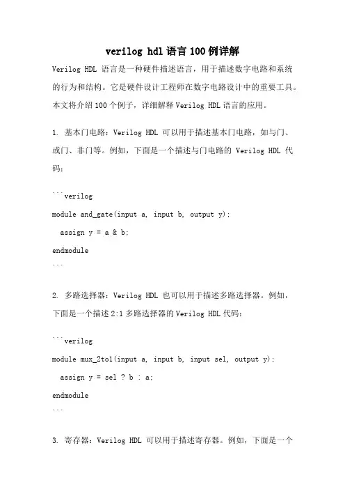
verilog hdl语言100例详解Verilog HDL语言是一种硬件描述语言,用于描述数字电路和系统的行为和结构。
它是硬件设计工程师在数字电路设计中的重要工具。
本文将介绍100个例子,详细解释Verilog HDL语言的应用。
1. 基本门电路:Verilog HDL可以用于描述基本门电路,如与门、或门、非门等。
例如,下面是一个描述与门电路的Verilog HDL代码:```verilogmodule and_gate(input a, input b, output y);assign y = a & b;endmodule```2. 多路选择器:Verilog HDL也可以用于描述多路选择器。
例如,下面是一个描述2:1多路选择器的Verilog HDL代码:```verilogmodule mux_2to1(input a, input b, input sel, output y);assign y = sel ? b : a;endmodule```3. 寄存器:Verilog HDL可以用于描述寄存器。
例如,下面是一个描述8位寄存器的Verilog HDL代码:```verilogmodule register_8bit(input [7:0] d, input clk, input reset, output reg [7:0] q);always @(posedge clk or posedge reset)if (reset)q <= 0;elseq <= d;endmodule```4. 计数器:Verilog HDL可以用于描述计数器。
例如,下面是一个描述8位计数器的Verilog HDL代码:```verilogmodule counter_8bit(input clk, input reset, output reg [7:0] count);always @(posedge clk or posedge reset)if (reset)count <= 0;elsecount <= count + 1;endmodule```5. 加法器:Verilog HDL可以用于描述加法器。
西北工业大学《串行数据检测器》实验报告学院:软件与微电子学院学号:2008303538 姓名:陈昊专业:微电子学实验时间:2010年11月实验地点:实验室及宿舍指导教师:曾惠敏西北工业大学2010 年11 月*/module mux_8(addr, in1, in2, in3, in4, in5,in6,in7,in8,mout,ncs); input [2:0] addr; //输入的地址端,3位选择开关input [3:0] in1,in2,in3,in4,in5,in6,in7,in8; //8路数据端输入input ncs; //使能信号output [3:0] mout; //一路输出reg [3:0] mout; //输出声明为寄存器类型always @(addr or in1 or in2 or in3 or in4 or in5 or in6 or in7 or in8 or ncs) //8路输入或者选择开关或者使能信号发生变化则条件触发beginif(!ncs) //低电平使能case(addr)3'b000: mout = in1; //选择开关的3位对应000时,输出等于in1输入;3'b001: mout = in2; //选择开关的3位对应001时,输出等于in1输入;3'b010: mout = in3; //选择开关的3位对应010时,输出等于in1输入;3'b011: mout = in4; //选择开关的3位对应011时,输出等于in1输入;3'b100: mout = in5; //选择开关的3位对应100时,输出等于in1输入;3'b101: mout = in6; //选择开关的3位对应101时,输出等于in1输入;3'b110: mout = in7; //选择开关的3位对应110时,输出等于in1输入;3'b111: mout = in8; //选择开关的3位对应111时,输出等于in1输入;endcaseelsemout = 0; //使能信号高电平时输出一直为0;endendmodule2.编写测试模块test_mux_8.v如下/*** @File test_mux_8.v* @Synopsis 这是8路数据选择器mux_8的测试模块* @Author 陈昊, @* @Version 1* @Date 2010-11-05*//* Copyright(0) 2010-* By 陈昊* All right reserved*/`timescale 1ns/1nsmodule test_mux_8;wire[3:0] mout; //声明输出为线网型,4位reg [3:0] in1,in2,in3,in4,in5,in6,in7,in8; //声明8路输入信号reg [2:0] addr; //3位的选择开关,寄存型类型reg ncs; //1位的寄存器型使能信号//-------------------------------------------------------------产生测试信号------------------------------------------------------ initialbeginncs=0; //在初始化模块里将使能信号置为0,让选择器正常工作in8={$random}%16; //使用系统任务$random产生一个0至15之间的数in1={$random}%16; //并赋予输入in2={$random}%16;in3={$random}%16;in4={$random}%16;in5={$random}%16;in6={$random}%16;in7={$random}%16;addr=3'b000; //让选择开关的3位初始对应为000.repeat(5) //重复下面的语句块5次,赋5次值 begin#10 in8={$random}%16;in1={$random}%16;in2={$random}%16;in3={$random}%16;in4={$random}%16;in5={$random}%16;in6={$random}%16;in7={$random}%16;addr=addr+1; //每执行一次后改变一次选择开关的值,加1end#10 $stop;end//-------------------------------------------------------------------------------------------------------------------------------2.选择Altera STRATIX器件库利用Synplify Pro综合产生的RTL级电路如下五、分析与讨论。
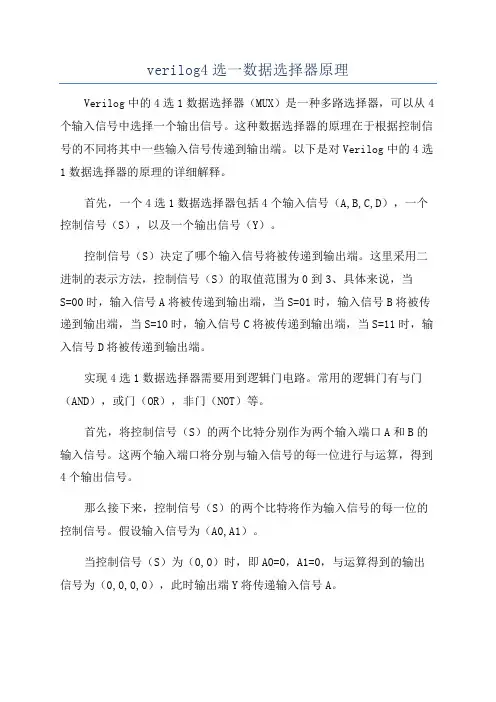
verilog4选一数据选择器原理Verilog中的4选1数据选择器(MUX)是一种多路选择器,可以从4个输入信号中选择一个输出信号。
这种数据选择器的原理在于根据控制信号的不同将其中一些输入信号传递到输出端。
以下是对Verilog中的4选1数据选择器的原理的详细解释。
首先,一个4选1数据选择器包括4个输入信号(A,B,C,D),一个控制信号(S),以及一个输出信号(Y)。
控制信号(S)决定了哪个输入信号将被传递到输出端。
这里采用二进制的表示方法,控制信号(S)的取值范围为0到3、具体来说,当S=00时,输入信号A将被传递到输出端,当S=01时,输入信号B将被传递到输出端,当S=10时,输入信号C将被传递到输出端,当S=11时,输入信号D将被传递到输出端。
实现4选1数据选择器需要用到逻辑门电路。
常用的逻辑门有与门(AND),或门(OR),非门(NOT)等。
首先,将控制信号(S)的两个比特分别作为两个输入端口A和B的输入信号。
这两个输入端口将分别与输入信号的每一位进行与运算,得到4个输出信号。
那么接下来,控制信号(S)的两个比特将作为输入信号的每一位的控制信号。
假设输入信号为(A0,A1)。
当控制信号(S)为(0,0)时,即A0=0,A1=0,与运算得到的输出信号为(0,0,0,0),此时输出端Y将传递输入信号A。
当控制信号(S)为(0,1)时,即A0=0,A1=1,与运算得到的输出信号为(0,1,0,0),此时输出端Y将传递输入信号B。
当控制信号(S)为(1,0)时,即A0=1,A1=0,与运算得到的输出信号为(0,0,1,0),此时输出端Y将传递输入信号C。
当控制信号(S)为(1,1)时,即A0=1,A1=1,与运算得到的输出信号为(0,0,0,1),此时输出端Y将传递输入信号D。
最后,将4个输出信号通过或门进行运算,得到输出信号Y。
具体地,将4个输出信号的每一位进行或运算,得到的结果就是输出信号Y的每一位。
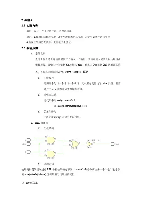
2 实验22.1 实验内容题目:设计一个1位的二选一多路选择器要求:1.使用门级描述实现 2.使用逻辑表达式实现 3.使用if条件语句实现4.出现正确的仿真波形,无需板子上验证。
2.2 实验步骤1.系统设计设计1位2选1选通器需要三个输入一个输出,其中中输入需要1根地址线两根数据线。
设输入一位数据a,b,地址为addr,输出为Out,根据2to1选通器的特_______点,可得其逻辑表达式为:out=a·addr+b·addr(1)门级描述需要两个与门一个非门一个或门,其中所有变量均为wire类型,且需要三个wire类型中间变量储存信号。
(2)逻辑表达式源代码中用assign out=sel?a:b;或assign out=(a&sel)|(b&~sel);(3)If条件语句If语句在always语句中进行判断。
2.RTL原理图(1)门级结构(2)逻辑语句使用两种逻辑语句进行RTL分析结果略有不同,out=sel?a:b;会分析出来一个2选1选通器而out=(a&sel)|(b&~sel);分析结果与门级结构类似1)out=sel?a:b;2)out=(a&sel)|(b&~sel);(3)if语句3.重要源代码及注释(1)门级结构module mux2_1(a,b,out,addr);input a,b,addr;output out;wire naddr,a1,b1;//定义中间变量not (naddr,addr);and (b1,b,naddr);and (a1,a,addr);or (out,a1,b1);endmodule(2)逻辑语句module luoji(input a,input b,input sel,output out);assign out=(a&sel)|(b&~sel);endmodule(3)if语句module mux2_1if(a,b,sel,out);input a,b,sel;output out;reg out;always@(a or b or sel)beginif(sel) out=a;else out=b;end2.3 结果分析1.Testbench代码(3种方式testbench 中代码类似,此处以if语句为例)module mux2_1if_tb();reg a,b,sel;mux2_1if m1(a,b,sel,out);initialbegina=0;b=0;sel=0;endalwaysbegin#10 a<=~a;endalwaysbegin#20 b<=~b;endalwaysbegin#15 sel<=1;#8 sel<=0;endendmodule2.仿真波形图(1)门级结构(2)逻辑语句(3)If语句3.说明三种方式均定义当选择端值为1时输出a,选择端值为0输出b;其中逻辑语句与if语句testbench部分代码相同,门级结构咯有不同,三种波形仿真图像均正确,符合2选1选通器功能。
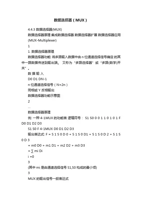
数据选择器(MUX)4.4.3 数据选择器(MUX)数据选择器原理集成数据选择器数据选择器扩展数据选择器应用(MUX-Multiplexer)11. 数据选择器原理数据选择器功能: 将多路输入数据中由n位通道选择信号确定的其中一路数据传送到输出端。
又称为“多路选择器”或“多路(数字)开关”。
数据输入D0 D1 DN-1n位通道选择信号(N=2n)同相或 Y 反相输出数据选择器功能示意图2…数据选择器原理例: 一种4-1MUX的功能表逻辑符号: S1 S0 0 0 1 1 0 1 0 1 F D0 D1 D2 D3S1 S0 F 4-1MUX D0 D1 D2 D3输出表达式: F = S 1 S 0 D 0 + S 1 S 0 D1 + S 1 S 0 D 2 + S 1 S 0 D 3= m0 D0 + m1 D1 + m2 D2 + m3 D3= ∑ mi Dii =03(其中mi是由通道选择信号S1,S0构成的最小项)3MUX的输出信号一般表达式2n -1 MUX的输出信号一般表达式:F = m 0 D 0 + m1 D1 + ? ? ? + m 2 n ? 1 D 2 n ? 1 =2 n ?1 i=0∑m Dii(其中mi 是n 位通道选择信号构成的最小项)42. 集成数据选择器例:8-1 MUX 74151S2X功能表使能 E 1 0 0 0 0 0 0 0 0 输出 Y 0 D0 D1 D2 D3 D4 D5 D6 D7 Y 1 D0 D1 D2 D3 D4 D5 D6 D7通道选择 S1 S0X X输出表达式为:Y = E (∑ mi Di )i =07(mi 是S2,S1,S0构成的最小项)0 0 0 0 1 1 1 10 0 1 1 0 0 1 10 1 0 1 0 1 0 1574151逻辑符号与引脚排列D0 D1 D2 D3 D4 D5 D6 D7 E S2 S1 S0Y8YD3 D2 D1 D0 Y Y G GND11674HC151Vcc D4 D5 D6 D7 S0 S1 S274LS151 74HC1516具有三态输出的集成数据选择器例:8-1 MUX 74251 功能表S2X通道选择 S1 S0X X0 0 0 0 1 1 1 10 0 1 1 0 0 1 10 1 0 1 0 1 0 1使能 E 1 0 0 0 0 0 0 0 0输出 Y Z D0 D1 D2 D3 D4 D5 D6 D7 Y Z D0 D1 D2 D3 D4 D5 D6 D7(Z:高阻态)73. 数据选择器扩展例:用2片74151扩展成16-1MUXY ≥1 Y &- 通道扩展YY 74151(2)YG A 2 A1 S00 E S2 S 1 AD7 D6 D 5 D4 D 3 D2 D1 D0 1E A2 A 0 G S2 S11SA 0D7 D 6 D5 D4 D3 D2 D 1 D0D15 D14 D13 D12 D11 D10 D 9D8S A A A A33 S2 2 S11 S00D7 D6 D 5 D4 D3 D2 D1 D08数据选择器扩展 - 位扩展例:两位数的8-1 数据选择电路 S2 S1 S0 0 0 0 0 0 1 0 1 0 0 1 1 1 0 0 1 0 1 1 1 0 1 1 1 Y1 Y0 I10 I00 I11 I01 I12 I02 I13 I03 I14 I04 I15 I05 I16 I06 I17 I07 I17 I10 I11D0 D1I00 I01D0 D18-1 MUXY0I07D7 S ~S E 2 08-1 MUXY1D7 S ~S E 2 03S2~ S0 E94. 数据选择器应用-多通道数据传输例:I 0 8-1 I 1 MUX I2 I3 Y I4 I5 I6 I 7 S2 S1 S0S2 S1 S0公共数据线Y0 Y1 Y2 Y3 D Y4 Y5 Y6 A2 A1A0 Y71-8 DEMUXA2 A1 A0利用数据选择器与数据分配器实现多路数据的分时传输10数据选择器应用-实现逻辑函数任何逻辑函数都可表示成最小项之和形式:F =∑ m (此 m 是由F的输入变量构成的最小项)i iiMUX的输出表达式: Y =∑2 n ?1i =0mi Di(此mi是由通道选择信号构成的最小项)一般,当用具有n个通道选择端的MUX实现n变量的逻辑函数时,只需将逻辑函数的输入变量与MUX的通道选择端一一对应,并令逻辑函数中mi所对应MUX输出表达式中的Di=1,其余项对应的Di=0,即可实现。
verilog primitive语法Verilog Primitive语法是硬件描述语言Verilog中的一种基本元素,用于描述数字电路中的基本逻辑功能和时序行为。
本文将介绍Verilog Primitive语法的基本结构和常用的几种类型,以及它们在设计数字电路中的应用。
一、基本结构Verilog Primitive语法由三部分组成:关键字、端口声明和行为描述。
关键字用于指定基本元件的类型,如AND、OR、NOT等。
端口声明用于定义基本元件的输入和输出端口,包括端口的名称、信号类型和方向。
行为描述则是通过Verilog的编程语言特性,对基本元件的功能进行描述和定义。
二、常用类型Verilog Primitive语法中常用的类型有:1. 逻辑门(Logic Gates):包括AND、OR、NOT、NAND、NOR、XOR 等逻辑门,在数字电路中常用于实现各种逻辑功能。
2. 编码器(Encoders):包括优先编码器(Priority Encoder)和旋转编码器(Rotary Encoder),用于将输入信号编码成二进制输出。
3. 译码器(Decoders):用于将二进制输入信号解码成多路输出信号,常用于实现多路选择器和存储器等。
4. 多路选择器(Multiplexers):用于实现多路选择功能,根据控制信号选择一个输入信号输出。
5. 触发器(Flip-Flops):包括D触发器、JK触发器、T触发器等,用于存储和延时信号。
6. 计数器(Counters):用于计数和计时信号,在时序电路中广泛应用。
三、应用场景Verilog Primitive语法在数字电路设计中有着广泛的应用,以下列举几个常见的场景:1. 组合逻辑电路设计:通过逻辑门、编码器、译码器和多路选择器等基本元件的组合,实现各种逻辑功能的设计。
2. 触发器和计数器的设计:通过触发器和计数器实现时序电路的设计,如状态机、定时器等。
3. 存储器和寄存器的设计:通过触发器和多路选择器等元件的组合,实现存储和读取数据的功能。

内容1 多路选择器Multiplexer此处所说的多路选择器,为组合逻辑电路中的多路多路选择器:多路输入,一路输出。
1.1 不带优先级的多路选择器1.1.1 使用case语句描述此处以4选1多路选择器为例:代码1.1 4选1多路选择器(可综合)`timescale 1ns/1nsmodule multiplexer(input iA,input iB,input iC,input iD,input [1:0] iSel,output reg oQ);always @ (*)case (iSel)2'b00 : oQ = iA;2'b01 : oQ = iB;2'b10 : oQ = iC;2'b11 : oQ = iD;endcaseendmodule第10~16行,使用case语句来实现4选1多路选择器。
因为是2^n个case选项,所以此处没有使用default语句。
下面我会使用一个3选1的多路选择器来说明default的作用。
always @ (*)case (iSel)2'b00 : oQ = iA;2'b01 : oQ = iB;2'b10 : oQ = iC;2'b11 : oQ = iD;endcase图1.1 4选1多路选择器的RTL视图由图1.1所示,在2^n个case选项时,没有加上default语句,其综合的结果为并行的MUX。
代码1.2 4选1多路选择器testbench(不可综合,仅用于仿真)`timescale 1ns/1nsmodule multiplexer_tb;reg i_a, i_b, i_c, i_d;reg [1:0] i_sel;wire o_q;initial begini_a = 1; i_b = 0; i_c = 0; i_d = 0;#20 i_a = 1; i_b = 0; i_c = 1; i_d = 1;#20 i_a = 0; i_b = 0; i_c = 1; i_d = 0;#20 i_a = 1; i_b = 1; i_c = 1; i_d = 0;endinitial begini_sel = 2'b00;#20 i_sel = 2'b01;#20 i_sel = 2'b10;#20 i_sel = 2'b11;#20 $stop;endmultiplexer multiplexer_inst(.iA (i_a),.iB (i_b),.iC (i_c),.iD (i_d),.iSel (i_sel),.oQ (o_q));endmodule第3~5行声明了一些变量,使用的标准为:映射为所需测试模块的输入信号,即需要使用initial 或always来给出激励,因此多声明为reg类型;而映射为所需测试模块的输出信号,不需要激励,声明为wire类型即可。
湘潭大学实验报告课程名称实用数字电子技术基础实验名称多路选择器页数 2专业网络工程班级2班同组者姓名无组别学号 2015551610 姓名黄伟雄实验日期2016/5/15一、实验目的1.设计一个2选1多路选择器。
2.进一步熟悉Quartus Ⅱ的Verilog HDL文本设计流程,掌握组合电路的设计仿真和硬件测试。
二、实验要求据实验内容写出实验报告,包括程序设计、软件编译、仿真分析、硬件测试和详细实验过程;给出程序分析报告、仿真波形图及其分析报告。
三、实验原理在数字信号的传递过程中,有时需要从多路输入数据中选出某一路数据,完成此功能的逻辑器件称为数据选择器,即多路开关,简称MUX。
2选1多路选择器能在选择信号的控制下,从2路输入信号中选择其中的一路数据送到输出口。
其真值表如下:四、实验内容1.多路选择器的设计:利用Quartus Ⅱ完成2选1多路选择器的文本编辑输入(MUX21.v)和仿真测试等步骤,给出仿真波形。
2.在实验系统上进行硬件测试,验证此设计的功能。
对于引脚锁定和硬件下载测试,a和b分别接不同频率的时钟;3.输出信号接蜂鸣器。
最后进行编译、下载和硬件测试实验(通过按键1来控制s,可使蜂鸣器输出不同的音调)。
五、实验环境与设备在实验室用计算机和试验箱进行实验。
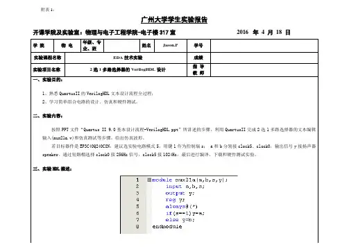
六、实验代码设计(含符号说明)module MUX21(A,B,S,Y);input A,B,S ;output Y ;wire Y ;assign Y=S?B:A ;endmodule七、实验检验与测试a接256Hz的蜂鸣器,b接1024Hz蜂鸣器。
灯亮(s为1)时b响,灯灭(s 为0)时a响。
八、测试数据详细的见MUX21文件夹里的数据九、实验过程中出现的问题及处理情况(包括实验现象、原因分析、排故障的方法等)1.下载程序到机箱时,按键没有任何反应,找不出原因,后来通过仔细的检查与比对,发现原来引脚锁定那一步,每个信号对应的Location栏内选错了引脚号,后来改正后,实验结果如预期一致。
用Verilog语言实现三位四选一多路选择器Verilog语言是一种硬件描述语言,用于描述数字电路的行为和结构。
三位四选一多路选择器是一种常见的数字电路,它有三个输入位和四个输出位。
根据输入位的不同组合,选择其中一个输出位输出。
下面是使用Verilog语言实现三位四选一多路选择器的代码:```verilogmodule mux_3to1(input [2:0] select, input [3:0] data, output reg out);case (select)3'b000: out = data[0];3'b001: out = data[1];3'b010: out = data[2];3'b011: out = data[3];default: out = 1'bx; // Invalid selectionendcaseendendmodule```在上述代码中,我们定义了一个名为`mux_3to1`的模块,该模块有三个输入位`select`和四个输入位`data`,以及一个输出位`out`。
`select`输入位用于选择要输出的数据位,`data`输入位是要选择的数据位,`out`输出位是最终选择的数据。
在`always`块内,我们使用`case`语句根据`select`的值选择要输出的数据位。
当`select`的值为`3'b000`时,输出`data[0]`;当`select`的值为`3'b001`时,输出`data[1]`;以此类推。
如果`select`的值不在这些范围内,则输出`1'bx`,表示无效选择。
这是一个简单的三位四选一多路选择器的Verilog实现。
你可以根据需要修改和扩展该代码,以满足特定的设计要求。
verilog mux用法Verilog MUX(多路复用器)的用法在数字电路设计中,多路复用器(MUX)是一种常用的逻辑电路组件。
它可以从多个输入信号中选择一个输出信号,并根据控制信号决定输出的内容。
Verilog是一种硬件描述语言,非常适合用于设计和建模数字系统。
Verilog语言提供了一种简洁而灵活的方式来实现MUX的功能。
下面将介绍如何使用Verilog来创建MUX电路。
首先,需要声明输入和输出端口。
在Verilog中,输入和输出端口可以使用`input`和`output`关键字来定义。
假设我们要设计一个4:1的MUX电路,有4个输入(A, B, C, D)和1个输出(Y),则可以使用以下代码进行声明:```module mux4to1 (input wire A, B, C, D, input wire [1:0] Sel, output reg Y);```接下来,需要使用用于控制MUX输出的逻辑来实现MUX的功能。
在这个例子中,我们使用了一种简单的方式:根据2位选择信号Sel的值进行判断,并将对应的输入信号赋值给输出信号。
根据选择信号的不同,MUX可以选择输出A、B、C或D。
```always @(A, B, C, D, Sel)begincase (Sel)2'b00: Y = A;2'b01: Y = B;2'b10: Y = C;2'b11: Y = D;endcaseend```最后,需要在测试平台上验证MUX电路的功能。
可以通过实例化MUX模块,提供不同的输入和选择信号,然后观察输出是否符合预期。
```mux4to1 u1(.A(A_input), .B(B_input), .C(C_input), .D(D_input), .Sel(Sel_input), .Y(output));```以上代码片段提供了一个简单的MUX 4:1电路的Verilog实现。