英文
Because of the rapid development of our economy resulting in the car number of large and medium-sized cities surged and the urban traffic, is facing serious test, leading to the traffic problem increasingly serious, its basically are behaved as follows: traffic accident frequency, to the human life safety enormous threat, Traffic congestion, resulting in serious travel time increases, energy consumption increase; Air pollution and noise pollution degree of deepening, etc. Daily traffic jams become people commonplace and had to endure. In this context, in combination with the actual situation of urban road traffic, develop truly suitable for our own characteristics of intelligent signal control system has become the main task.
Preface
In practical application at home and abroad, according to the actual traffic signal control application inspection, planar independent intersection signal control basic using set cycle, much time set cycle, half induction, whole sensor etc in several ways. The former two control mode is completely based on planar intersection always traffic flow data of statistical investigation, due to traffic flow the existence of variable sex and randomicity, the two methods have traffic efficiency is low, the scheme, the defects of aging and half inductive and all the inductive the two methods are in the former two ways based on increased vehicle detector and according to the information provided to adjust cycle is long and green letter of vehicle, it than random arrived adaptability bigger, can make vehicles in the parking cord before as few parking, achieve traffic flowing effect
In modern industrial production,current,voltage,temperature, pressure, and flow rate, velocity, and switch quantity are common mainly controlled parameter. For example: in metallurgical industry, chemical production, power engineering, the papermaking industry, machinery and food processing and so on many domains, people need to transport the orderly control. By single chip microcomputer to control of traffic, not only has the convenient control, configuration simple and flexible wait for an advantage, but also can greatly improve the technical index by control quantity, thus greatly improve product quality and quantity. Therefore, the monolithic integrated circuit to the traffic light control problem is an industrial production we often encounter problems.
In the course of industrial production, there are many industries have lots of traffic equipment, in the current system, most of the traffic control signal is accomplished by relays, but relays response time is long, sensitivity low, long-term after use, fault opportunity increases greatly, and adopts single-chip microcomputer control, the accuracy of far greater than relays, short response time, software reliability, not because working time reduced its performance sake, compared with, this solution has the high feasibility.
About AT89C51
(1)function characteristics description:
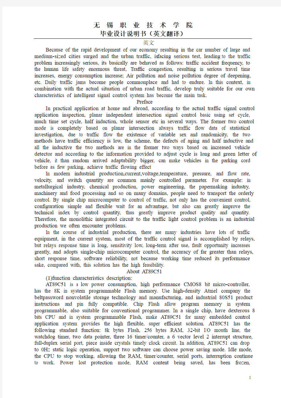
AT89C51 is a low power consumption, high performance CMOS8 bit micro-controller, has the 8K in system programmable Flash memory. Use high-density Atmel company the beltpassword nonvolatile storage technology and manufacturing, and industrial 80S51 product instructions and pin fully compatible. Chip Flash allow program memory in system programmable, also suitable for conventional programmer. In a single chip, have dexterous 8 bits CPU and in system programmable Flash, make AT89C51 for many embedded control application system provides the high flexible, super efficient solution. AT89C51 has the following standard function: 8k bytes Flash, 256 bytes RAM, 32-bit I/O mouth line, the watchdog timer, two data pointer, three 16 timer/counter, a 6 vector level 2 interrupt structure, full-duplex serial port, piece inside crystals timely clock circuit. In addition, AT89C51 can drop to 0Hz static logic operation, support two software can choose power saving mode. Idle mode, the CPU to stop working, allowing the RAM, timer/counter, serial ports, interruption continue to work. Power lost protection mode, RAM content being saved, has been frozen,
microcontroller all work stop, until the next interruption or hardware reset so far. As shown in
(2)interrupt introduction
AT89C51 has six interrupt sources: two external interruption, (and), three timer interrupt (timer 0, 1, 2) and a serial interrupts. Each interrupt source can be passed buy bits or remove IE the relevant special register interrupt allow control bit respectively make effective or invalid interrupt source. IE also includes an interrupt allow total control bit EA, it can be a ban all interrupts. IE. Six is not available. For AT89C51, IE. 5 bits are also not be used. User software should not give these bits write 1. They AT89 series for new product reserved. Timer 2 can be TF2 and the T2CON registers EXF2 or logical triggered. Program into an interrupt service, the sign bit can be improved by hardware qing 0. In fact, the interrupt service routine must determine whether TF2 or EXF2 activation disruption, the sign bit must also by software qing 0. Timer 0 and 1 mark a timer TF0 and TF1 has been presented in the cycle count overflow S5P2 074 bits. Their value until the next cycle was circuit capture down. However, the timer 2 marks a TF2 in count overflow of the cycle of S2P2 074 bits, in the same cycle was circuit capture down
About 8255 chip
1.8255 features:
(1)A parallel input/output LSI chips, efficacy of I/O devices, but as CPU bus and peripheral interface.
(2)It has 24 programmable Settings of I/O mouth, even three groups of 8 bits I/O mouth to mouth, PB mouth and PA PC mouth. They are divided into two groups 12 I/O mouth, A group including port A and C mouth (high four, PC4 ~ PC7), including group B and C port B mouth (low four, PC0 ~ PC3). A group can be set to give basic I/O mouth, flash control (STROBE) I/O flash controlled, two-way I/O3 modes, Group B can only set to basic I/O or flash controlled the I/O, and these two modes of operation mode entirely by controlling registers control word decision.
2. 8255 pins efficacy:
(1). RESET: RESET input lines, when the input outside at high levels, all internal registers (including control registers) were removed, all I/O ports are denoting input methods.
(2). CS: chip choose a standard lamp line 1, when the input pins for low levels, namely/CS = 0, said chip is selected, allow 8255 and CPU for communications, / CS = 1, 8255 cannot with CPU do data transmission.
(3). RD: read a standard lamp line 1, when the input pins for low levels, namely/RD = 0 and/CS = 0, allow 8255 through the data bus to the CPU to send data or state information, namely the CPU 8255 read from the information or data.
(4). The WR: write a standard lights, when the input pins for low levels, namely/WR = 0 and/CS = 0, allows the CPU will data or control word write 8255.
(5). D7: three states D0 ~ two-way data bus, 8255 and CPU data transmission channel, when the CPU execution input/output instruction, through its realization 8 bits of data read/write operation, control characters and status information transmitted through the data bus.
(6). PA0 ~ PA7: port A input and output lines, A 8 bits of data output latches/buffers, an 8 bits of data input latches.
(7). PB0 ~ PB7: port B input and output lines, a 8 bits of I/O latches, an 8 bits of input and output buffer.
(8). PC0 ~ PC7: port C input and output lines, a 8 bits of data output latches/buffers, an 8 bits of data input buffer. Port C can through the way of working setting into two four ports, every 4 digit port contains A 4 digit latches, respectively with the port A and port B cooperate to use, can be used as control standard lights output or state standard lights input ports.
(9). A0, A1: address selection line, used to select the PA 8255 mouth, PB mouth, PC mouth and controlling registers.
When A0=0, A1= 0, PA mouth be chosen;
When A0=0, A1 = 1, PB mouth be chosen;
When A0=0, A1 = 1, PC mouth be chosen;
When A0=1, A1= 1, control register is selected.
Concerning seven section LED display introduction
Through light emitting diode chip appropriate link (including series and parallel) and appropriate optical structure. May constitute a luminous display light-emitting segments or shine points. By these luminous segments or shine point can be composed digital tube, symbols tube, m word pipe, tube, multilevel matrix display tube etc. Usually the digital tube, symbols tube, m word tube were called stroke display, but the stroke displays and matrix tube
collectively referred to as character displays.
1. The LED display classification
(1) by word high marks: stroke monitors word high least 1mm (monolithic integrated type more digital tube word high in commonly 2 ~ 3mm). Other types of stroke display tiptop 1.27 mm (0.5 inch) even up to hundreds of mm.
(2) color-coded score red, orange, yellow, green and several kinds.
(3) according to the structure points, reflecting cover type, a single point-elastic and monolithic integrated type.
(4) from the luminous section electrode connection mode of points of anode and cathode two kinds.
2. LED display parameters
Due to the LED display is LED based, so its light, and the electrical characteristics and ultimate meaning of the parameters with most of the same light emitting diode. But because the LED monitor containing multiple light emitting diode, it must has the following specific parameters:
(1) the luminous intensity ratio
Due to the digital tube paragraphs in the same driving voltage, each are not identical, so positive current each different. The luminous intensity All segments of the luminous intensity values the ratio of the maximum and minimum values for the luminous intensity ratio. The ratio between 2.3 in 1.5 ~, the maximum cannot exceed 2.5.
(2) pulse positive current
IF each segment of typical strokes displays for positive dc working current IF, then the pulse, positive current can be far outweigh.someotherwordpeopledontthinkoffirst. Pulse 390v smaller, pulse positive current can be bigger.
Traffic signal control type
The purpose of the traffic signal control are three: first,in time and space space intersection traffic in different directions,control traffic operation order; Second, make on planar cross the road network on the people and objects of transport at the highest efficiency, Third, as the road users to provide necessary information, and help them to effectively use the traffic facilities. Road traffic signal control of basic types have many points method.
According to the control geometry characteristic is divided into: single intersection control - point control, the traffic trunk lines of coordinated control - wire, traffic network coordination control surface controlling; -- According to the control principle differentiates: timing control, induced control and adaptive control.
About watch-dog circuit
By single-chip computers.the micro computer system, because of single chip work often can be affected by external electromagnetic interference, causing program run fly while into dead circulation, the program's normal operation be interrupted by single chip microcomputer control system was unable to work, can cause the whole system of come to a standstill, happen unpredictable consequences, so out of microcontroller running status real-time.according consideration, they generate a specially used for monitoring microcontroller program running state of the chip, commonly known as "watchdog" (watchdog).
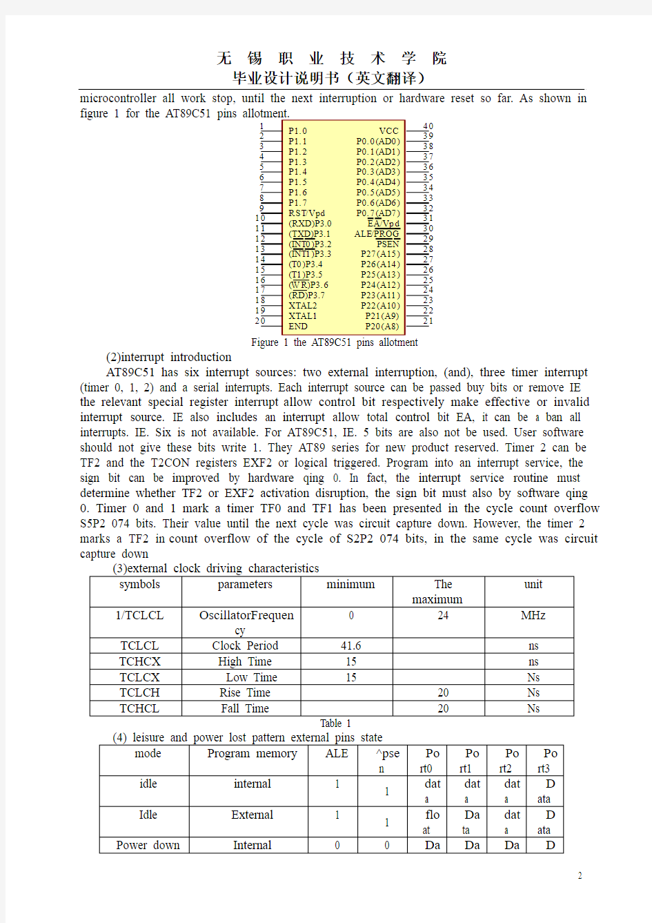
MAX692 was slightly system monitoring circuit chip, have back-up battery switching, power lost discriminant functions monitoring, the watchdog. The encapsulation and pin instructions as figure2shows.
Figure 2 MAX692 encapsulation and pins
Watch-dog circuit application, make SCM can in no condition to achieve continuous work, its working principle is: the watchdog chip and MCU an I/O pins are linked together, the I/O pins through program control it regularly to the watchdog of the pins on into high level (or the low level), this program statement is scattered on SCM other control statements, once among single-chip due to the interference makes application run into a fly after the procedures section into dead circulation state, write the watchdog pins program cannot be executed, this time, the watch-dog circuit will be without microcontroller sent signals, then at it and MCU reset pin connected pin reset signal give out a a, make SCM reposition occurs, namely the program from program memory splittext started, so we realized the MCU automatic reset.
Infrared detection circuit
The infrared radiation photon in semiconductor materials stimutes the non-equilibrium carriers (electronic or holes), cause electrical properties change. Because carrier does not escape in vitro, so called within the photoelectric effect. Quantum photoelectric effect high sensitivity, response speed heat detectors much faster, is optional detectors. In order to achieve the best performance, generally need worked in low temperature. Photoelectric detector can be divided into:
(1) optical type: also called photoconductive resistance. The incident photon stimulate the valence band uniform semiconductor electronic across forbidden band into the conduction band and left in valence band, cause cavitation increases, for electric conductance eigen light conductivity. From the band gaps of impurity level also can stimulate light into the conduction band or born carriers valence band, and for impurities light conductivity. The cutoff wavelength by impurity ionization energy (ie) decision. Quantum efficiencies below eigen optical and require lower working temperature.
(2) photovoltaic type: mainly p - n knot of light born volts effect. Energy more than the width of infrared photonic band gaps in "area and its nearby of electrons cavitation. Existing "electric field make hole into p area, electronic into n area, two parts appear potentials. Deoxidization device have voltage or current signal. Compared with optical detectors, pv detector detect rate more than forty percent of figure limit, Don't require additional bias electric field and load resistance, no power consumption, having a high impedance. These characteristics of preparation and use of the focal plane array bring great benefits.
(3) light emitting - Schottky potential barrier detector: metal and semiconductor contact, typically include PtSi/Si structure and form was Schott potential barrier, infrared photon through Si layer for PtSi absorption, electronic Fermi level, obtain energy leap over left cavitation potential barrier into the Si substrate, PtSi layer of electronic was collected, complete infrared detection. Make full use of Si integration technology, facilitate production, with lower cost and good uniformity wait for an advantage, but make it mass (1024 x 1024 even greater) focal plane array to make up for the defect of quantum low efficiency. Have strict
low temperature requirements. With this kind of detector, both at home and abroad has already produced as qualitative good thermography. Pt Si/Si structure made of FPA is the earliest IRFPA.
Timing counting and traffic calculation
Using MCS - 51 internal timer/counter for timing, cooperate software delay realizes the timer. This method hardware cost saving, cut allows the reader in timer/counter use, disruptions and programming get exercise and improve. Computation formula is as follows: TC = M - C
Type in, M for counter touch value, the value and the counter working way concerned.
For a traffic intersection, it can in the shortest possible time to achieve maximum traffic, even reached the best performance, we call in unit of time to achieve the maximum flow multi-energy for cars.
Use the equation: (traffic = traffic/time) to represent.
中文
由于我国经济的快速发展从而导致了汽车数量的猛增,大中型城市的城市交通,正面临着严峻的考验,从而导致交通问题日益严重,其主要表现如下:交通事故频发,对人类生命安全造成极大威胁;交通拥堵严重,导致出行时间增加,能源消耗加大;空气污染和噪声污染程度日益加深等。日常的交通堵塞成为人们司空见惯而又不得不忍受的问题。在这种背景下,结合我国城市道路交通的实际情况,开发出真正适合我们自身特点的智能信号灯控制系统已经成为当前的主要任务。
在实际应用上,根据对国内外实际交通信号控制应用的考察,平面独立交叉口信号控制基本采用定周期、多时段定周期、半感应、全感应等几种方式。前两种控制方式完全是基于对平面交叉口既往交通流数据的统计调查,由于交通流存在的变化性和随机性,这两种方式都具有通行效率低、方案易老化的缺陷,而半感应式和全感应式这两种方式是在前两种方式的基础上增加了车辆检测器并根据其提供的信息来调整周期长和绿信比,它对车辆随机到达的适应性较大,可使车辆在停车线前尽可能少停车,达到交通流畅的效果。
在现代化的工业生产中,电流、电压、温度、压力、流量、流速和开关量都是常用的主要被控参数。例如:在冶金工业、化工生产、电力工程、造纸行业、机械制造和食品加工等诸多领域中,人们都需要对交通进行有序的控制。采用单片机来对交通进行控制,不仅具有控制方便、组态简单和灵活性大等优点,而且可以大幅度提高被控制量的技术指标,从而能够大大提高产品的质量和数量。因此,单片机对交通灯的控制问题是一个工业生产中经常会遇到的问题。
在工业生产中,有很多行业有大量的交通灯设备,在现行系统中,大多数的交通控制信号都是用继电器来完成的,但继电器响应时间长,灵敏度低,长期使用之后,故障机会大大增加,而采用单片机控制,其精度远远大于继电器,响应时间短,软件可靠性高,不会因为工作时间缘故而降低其性能,相比而言,本方案具有很高的可行性。
关于AT89C51
(1)功能特征描述:
AT89C51是一种低功耗、高性能CMOS8位微控制器,具有8K 在系统可编程Flash 存储器。使用Atmel 公司高密度非易失性存储器技术制造,与工业80S51 产品指令和引脚完全兼容。片上Flash允许程序存储器在系统可编程,亦适于常规编程器。在单芯片上,拥有灵巧的8 位CPU 和在系统可编程Flash,使得AT89C51为众多嵌入式控制应用系统
提供高灵活、超有效的解决方案。AT89C51具有以下标准功能: 8k字节Flash,256字节RAM,32 位I/O 口线,看门狗定时器,2 个数据指针,三个16 位定时器/计数器,一个6向量2级中断结构,全双工串行口,片内晶振及时钟电路。另外,AT89C51 可降至0Hz 静态逻辑操作,支持2种软件可选择节电模式。空闲模式下,CPU停止工作,允许RAM、定时器/计数器、串口、中断继续工作。掉电保护方式下,RAM内容被保存,振荡器被冻结,单片机一切工作停止,直到下一个中断或硬件复位为止。如图1为8051引脚分配图。
(2)中断介绍
AT89C51有6个中断源:两个外部中断(和),三个定时中断(定时器0、1、2)和一个串行中断。每个中断源都可以通过置位或清除特殊寄存器IE 中的相关中断允许控制位分别使得中断源有效或无效。IE还包括一个中断允许总控制位EA,它能一次禁止所有中断。IE.6位是不可用的。对于AT89C51,IE.5位也是不能用的。用户软件不应给这些位写1。它们为AT89系列新产品预留。定时器2可以被寄存器T2CON中的TF2和EXF2的或逻辑触发。程序进入中断服务后,这些标志位都可以由硬件清0。实际上,中断服务程序必须判定是否是TF2 或EXF2激活中断,标志位也必须由软件清0。定时器0和定时器1标志位TF0 和TF1在计数溢出的那个周期的S5P2被置位。它们的值一直到下一个周期被电路捕捉下来。然而,定时器2的标志位TF2 在计数溢出的那个周期的S2P2被置位,在同一个周期被电路捕捉下来。
(4)空闲和掉电模式外部引脚状态
关于8255芯片
1. 8255特性:
(1) 一个并行输入/输出的LSI芯片,多功效的I/O器件,可作为CPU总线与外围的接口.
(2) 具有24个可编程设置的I/O口,即使3组8位的I/O口为PA口,PB口和PC口.它们又可分为两组12位的I/O口,A组包括A口及C口(高4位,PC4~PC7),B组包括B口及C口(低4位,PC0~PC3).A组可设置为基本的I/O口,闪控(STROBE)的I/O闪控式,双向I/O3种模式;B组只能设置为基本I/O或闪控式I/O两种模式,而这些操作模式完全由控制寄存器的控制字决定.
2. 8255引脚功效:
(1).RESET:复位输入线,当该输入端外于高电平时,所有内部寄存器(包括控制寄存器)均被清除,所有I/O口均被置成输入方式。
(2).CS:芯片选择旌旗灯号线,当这个输入引脚为低电平时,即/CS=0时,表示芯片被选中,允许8255与CPU进行通讯;/CS=1时,8255无法与CPU做数据传输。
(3).RD:读旌旗灯号线,当这个输入引脚为低电平时,即/RD=0且/CS=0时,允许8255通过数据总线向CPU发送数据或状态信息,即CPU从8255读取信息或数据。
(4).WR:写入旌旗灯号,当这个输入引脚为低电平时,即/WR=0且/CS=0时,允许CPU 将数据或控制字写入8255。
(5).D0~D7:三态双向数据总线,8255与CPU数据传送的通道,当CPU执行输入输出指令时,通过它实现8位数据的读/写操作,控制字和状态信息也通过数据总线传送。
(6).PA0~PA7:端口A输入输出线,一个8位的数据输出锁存器/缓冲器,一个8位的数据输入锁存器。
(7).PB0~PB7:端口B输入输出线,一个8位的I/O锁存器,一个8位的输入输出缓冲器。
(8).PC0~PC7:端口C输入输出线,一个8位的数据输出锁存器/缓冲器,一个8位的数据输入缓冲器。端口C可以通过工作方式设定而分成2个4位的端口,每个4位的端口包含一个4位的锁存器,分别与端口A和端口B配合使用,可作为控制旌旗灯号输出或状态旌旗灯号输入端口。
(9).A0,A1:地址选择线,用来选择8255的PA口,PB口,PC口和控制寄存器。
当A0=0,A1=0时,PA口被选择;
当A0=0,A1=1时,PB口被选择;
当A0=1,A1=0时,PC口被选择;
当A0=1,A1=1时,控制寄存器被选择。
有关七段LED显示器的介绍
通过发光二极管芯片的适当连接(包括串联和并联)和适当的光学结构。可构成发光显示器的发光段或发光点。由这些发光段或发光点可以组成数码管、符号管、米字管、矩阵管、电平显示器管等等。通常把数码管、符号管、米字管共称笔画显示器,而把笔画显示器和矩阵管统称为字符显示器。
1. LED显示器分类
(1)按字高分:笔画显示器字高最小有1mm(单片集成式多位数码管字高一般在2~3mm)。其他类型笔画显示器最高可达12.7mm(0.5英寸)甚至达数百mm。
(2)按颜色分有红、橙、黄、绿等数种。
(3)按结构分,有反射罩式、单条七段式及单片集成式。
(4)从各发光段电极连接方式分有共阳极和共阴极两种。
2. LED显示器的参数
由于LED显示器是以LED为基础的,所以它的光、电特性及极限参数意义大部分与发光二极管的相同。但由于LED显示器内含多个发光二极管,所以需有如下特殊参数:
(1) 发光强度比
由于数码管各段在同样的驱动电压时,各段正向电流不相同,所以各段发光强度不同。所有段的发光强度值中最大值与最小值之比为发光强度比。比值可以在1.5~2.3间,最大不能超过2.5。
(2) 脉冲正向电流
若笔画显示器每段典型正向直流工作电流为IF,则在脉冲下,正向电流可以远大于IF。脉冲占空比越小,脉冲正向电流可以越大。
交通信号控制类型
交通信号控制的目的有三点:第一,在时间上和空间上分隔交叉口不同方向的车流,控制车流的运行秩序;第二,使在平面交叉的道路网络上人和物的运输达到最高效率;第三,为道路使用者提供必要的信息,帮助他们有效地使用交通设施。道路交通信号控制的基本类型有多种分法。
按控制区几何特性划分为:单个交叉口的控制——点控、交通干线的协调控制——线控、交通网络的协调控制——面控;按控制原理划分:定时控制、感应控制、自适应控制。
关于看门狗电路
在由单片机构成的微型计算机系统中,由于单片机的工作常常会受到来自外界电磁场的干扰,造成程序的跑飞,而陷入死循环,程序的正常运行被打断,由单片机控制的系统无法继续工作,会造成整个系统的陷入停滞状态,发生不可预料的后果,所以出于对单片机运行状态进行实时监测的考虑,便产生了一种专门用于监测单片机程序运行状态的芯片,俗称"看门狗"(watchdog)。
MAX692是微系统监控电路芯片,具有后备电池切换、掉电判别、看门狗监控等功能。其封装和引脚说明如图2所示。
图2 MAX692封装和引脚
看门狗电路的应用,使单片机可以在无人状态下实现连续工作,其工作原理是:看门
狗芯片和单片机的一个I/O引脚相连,该I/O引脚通过程序控制它定时地往看门狗的这个引脚上送入高电平(或低电平),这一程序语句是分散地放在单片机其他控制语句中间的,一旦单片机由于干扰造成程序跑飞后而陷入某一程序段进入死循环状态时,写看门狗引脚的程序便不能被执行,这个时候,看门狗电路就会由于得不到单片机送来的信号,便在它和单片机复位引脚相连的引脚上送出一个复位信号,使单片机发生复位,即程序从程序存储器的起始位置开始执行,这样便实现了单片机的自动复位。
红外检测电路
红外辐射光子在半导体材料中激发非平衡载流子(电子或空穴),引起电学性能变化。因为载流子不逸出体外,所以称内光电效应。量子光电效应灵敏度高,响应速度比热探测器快得多,是选择性探测器。为了达到最佳性能,一般都需要在低温下工作。光电探测器可分为:
(1) 光导型:又称光敏电阻。入射光子激发均匀半导体中的价带电子越过禁带进入导带并在价带留下空穴,引起电导增加,为本征光电导。从禁带中的杂质能级也可激发光生载流子进入导带或价带,为杂质光电导。截止波长由杂质电离能决定。量子效率低于本征光导,而且要求更低的工作温度。
(2) 光伏型:主要是p-n结的光生伏特效应。能量大于禁带宽度的红外光子在结区及其附近激发电子空穴对。存在的结电场使空穴进入p区,电子进入 n 区,两部分出现电位差。外电路就有电压或电流信号。与光导探测器比较,光伏探测器背影限探测率大于40%;不需要外加偏置电场和负载电阻,不消耗功率,有高的阻抗。这些特性给制备和使用焦平面阵列带来很大好处。
(3) 光发射-Schottky势垒探测器:金属和半导体接触,典型的有PtSi/Si结构,形成Schott ky势垒,红外光子透过Si层为PtSi吸收,电子获得能量跃上 Fermi能级,留下空穴越过势垒进入Si衬底,PtSi层的电子被收集,完成红外探测。充分利用Si集成技术,便于制作,具有成本低、均匀性好等优势,可做成大规模(1024×1024甚至更大)焦平面阵列来弥补量子效率低的缺陷。有严格的低温要求。用这类探测器,国内外已生产出具有像质良好的热像仪。Pt Si/Si结构FPA是最早制成的IRFPA。
定时计数与车流量的计算
利用MCS-51内部的定时器/计数器进行定时,配合软件延时实现到计时。该方法节省硬件成本,切能够使读者在定时器/计数器的使用、中断及程序设计方面得到锻炼与提高。计算公式如下:
TC=M-C
式中,M为计数器摸值,该值和计数器工作方式有关。
对于一个交通路口来说,能在最短的时间内达到最大的车流量,就算是达到了最佳的性能,我们称在单位时间内多能达到的最大车流为车流量。
用公式:(车流量= 车流 / 时间)来表示。
交通灯控制器的设计 LG GROUP system office room 【LGA16H-LGYY-LGUA8Q8-LGA162】
电子设计自动化实训说明书 题目:交通灯控制器的设计 系部:信息与控制工程学院 专业:电子信息工程 班级: 06级1班 学生姓名: 朱清美学号: 015 指导教师:张建军 2009年12月21日 目录 1摘要............................................................... 2设计任务与要求..................................................... 3设计原理及框图..................................................... 4单元电路设计及仿真调试............................................. 状态控制器的设计................................................ 状态译码器设计及仿真调试........................................ 定时系统设计及仿真调试.......................................... 秒脉冲发生器设计................................................ 5个人总结 (14) 6参考文献........................................................... 1摘要: 分析了现代城市交通控制与管理问题的现状,结合城乡交通的实际情况阐述了交通灯控制系统的工作原理,给出了一种简单实用的城市交通灯控制系统的硬件电路设计方案。关键词:交通控制交通灯时间发生器定时器1 引言随着社会经济的发展,城市交通问题越来越引起人们的关注。人、车、路三者关系的协调,已成为交通管理部门需要解决的重要问题之一。城市交通控制系统是用于城市交通数据监测、交通信号灯控制与交通疏导的计算机综合管理系统,它是现代城市交通监控指挥系统中最重要的组成部分。随着城市机动车量的不断增加,许多大城市如北京、上海、南京等出现了交通超负荷运行的情况,因此,自80年代后期,这些城市纷纷修建城市高速道路,在高速道
编号: 毕业论文(设计) 题目智能交通信号灯控制系统设计 指导教师xxx 学生姓名杨红宇 学号201321501077 专业交通运输 教学单位德州学院汽车工程系(盖章) 二O一五年五月十日
德州学院毕业论文(设计)中期检查表
目 录 1 绪论............................................................................................................................ 1 1.1交通信号灯简介...................................................................................................... 1 1.1.1 交通信号灯概述.................................................................................................. 1 1.1. 2 交通信号灯的发展现状...................................................................................... 1 1.2 本课题研究的背景、目的和意义 ......................................................................... 1 1. 3 国内外的研究现状 ................................................................................................. 1 2 智能交通信号灯系统总设计.................................................................................... 2 2.1 单片机智能交通信号灯通行方案设计 ................................................................. 2 2.2 功能要求 ............................................................................... 错误!未定义书签。 3 系统硬件组成............................................................................................................ 4 4 系统软件程序设计.................................................................................................... 5 5 结论和展望................................................................................................................ 6 参考文献...................................................................................... 错误!未定义书签。 杨红宇 要: 但是传统的交通信号灯不已经不能满足于现代日益增长的交通压力,这些缺点体现在:红绿 以及车流量检测装置来实现交通信号灯的自控制,随着车流量来改变红绿灯1 绪论 1.1 1.1.1 为现代生活中必不可少的一部分。
Lesson eight 第八课 Ⅱ.翻译句子,并注意remain和above的词类和词义 2. In this case the voltage applied must remain unchanged. 在这种情况下,那个应用电压必须保持不变 4. If you take 3 from 8, 5 remain. 如果从8中拿走3,剩5. 6. The above property was discovered by Faraday. 法拉第发现以上性质。 8. Lenz states that the self-induced emf impedes any change of current and tends to support the former current value. The above is known as Lenz’s law. 楞茨陈述自感电动势阻止电流的变化而保持先前电流的值。上面就是我们所知的楞 次定律。 Ⅲ.翻译句子,注意some的词义 2. That radio receiver weighs some five kilograms. 那个无线接收器重五公斤。 4. Some element in the substance is not known. 物质中的一些元素是人们不知道的。 Ⅳ.翻译句子,注意句中one 的不同用法和词义。 2. This concept was discussed in Chapter One. 这个概念在第一张讨论过。 4. No one can lift this equipment. 没人能举起这件设备。 6. This chapter will deal with one of the three functions of a turning circuit. 这章我们将介绍螺旋电路三个功能中的一个。 8. Before one studies a system, it is necessary to define and discuss some important terms. 在研究一个系统之前,确定且讨论一些重要的术语是有必要的。 Ⅴ.画出句中的名词从句,说明其种类,并将句子译成汉语。 2. These experiments do not show which particles. 这些实验不能显示他们的粒子结构。 4. The operating point is determined by how much bias is used. 操作要点是被用多少偏压决定的。 6. It is not important how this voltage is produced. 这个电压是怎么产生的并不重要。 8. It may be questioned whether this approach is the best for the physicist. 这种方式最适合于医生可能会被质疑。 10. This ball may be used to determine whether that body is charged. 这个球可能用于检测是否身体是带电的。 12. It is known that charged particles emit electromagnetic waves whenever they are accelerated. 众所周知的当电子被加速他们就会发射电磁波。 14. The value of this factor determines how fast the amplitude of the current
南京师范大学中北学院
毕业设计(论文)开题报告
( 10 届)
题 目: 基于 PLC 智能交通灯控制系统设计
专 业: 电气工程及其自动化
姓 名: xxx 学 号: xxx
指导教师: xxx 职 称:
填写日期:
2014 年 2 月 20 日
南京师范大学中北学院教务处 制
开题报告填写要求
1.开题报告作为毕业设计(论文)答辩委员会对学生答辩资格
审查的依据材料之一。此报告应在指导教师指导下,由学生在毕业 设计(论文)工作前期内完成,经指导教师签署意见及院、系审查 后生效;
2.开题报告内容必须用黑墨水笔工整书写或按教务处统一设计 的电子文档标准格式(可从教务处网址上下载)打印,禁止打印在 其它纸上后剪贴,完成后应及时交给指导教师签署意见;
3.有关年月日等日期的填写,应当按照国标 GB/T 7408—94《数 据元和交换格式、信息交换、日期和时间表示法》规定的要求,一 律用阿拉伯数字书写。如“2011 年 4 月 26 日”或“2011-04-26”。
4.院系审查意见栏签章:自办专业盖中北学院教学院长签名章、 中北学院公章,非自办专业盖联办二级学院教学院长签名章、联办 二级学院公章。
毕 业 设 计(论 文)开 题 报 告
1.本课题的目的及研究意义:
随着我国交通事业的迅速发展,各种公交、运输汽车、私家车等车的急速增加,使 得城市道路交通日益堵塞,交通在许多城市已经成为“瓶颈”问题。因此,提高城市路 网的通行能力、实现道路交通的科学化管理迫在眉睫。
虽然各城市已在十字路口设置了交通灯,对交通进行了有效的疏通,但是随着社会、 经济的快速发展,原先的交通灯控制系统已经不能适应现在日益繁忙的交通状况。如何 改善交通灯控制系统,使其适应现在的交通状况,成为研究的课题。
传统的十字路口交通控制灯,通常的做法是:事先进行车流量的调查,运用统计的 方法将两个方向红绿灯的延时预先设置好。然而,实际上车辆流量的变化往往是不确定 的,有的路口在不同的时段甚至可能产生很大的差异。即使是经过长期运行、较适用的 方案,仍然会发生这样的现象:绿灯方向几乎没有什么车辆,而红灯方向却排着长队等 候通过。可见,统计的方法已不能适应迅猛发展的交通现状,更为现实的需要是:能有 一种能够根据车流量变化适时调节的交通灯控制系统。
我所要研究的就是基于 PLC 的智能交通灯控制系统。智能交通系统(ITS—— Intelligent Transport Systems)ITS 是一个跨学科、信息化、系统化的综合研究体系, 其主要内容是:将先进的人工智能技术、自动控制技术、计算机技术、信息与通讯技术 及电子传感技术等有效的集成,并应用于整个地面交通管理系统而建立的一种在大范围 内、全方位发挥作用的,实时、准确、高效的综合交通运输管理系统。由于交通系统具 有较强的非线性、模糊性和不确定性,是一个典型的分布式非线性系统,而且具有多种 信息来源、多传感器的特点,用传统的理论与方法很难对其进行有效的控制。把先进的 智能控制技术、信息融合技术、智能信息处理技术与交通管理技术结合起来,代表着城 市交通信号控制系统发展的方向。
智能交通的发展是现代社会经济发展的客观要求,交通运输是国民经济和现代社会 发展的基础。由于现代社会城市化速度越来越快、国民经济的高速增长、全球经济的一 体化进程加快、个人旅行与休闲时间的不断增加以及人们对交通需求越来越高,智能交 通便成为现代社会经济发展的客观要求。
贵州师范学院 电子课程设计报告书 班级11级1班 学生姓名王旭东 学号11030540094 专业电子信息科学与技术 院系物电学院 2014年6 月20 日
摘要 随着城市人口的快速增长和机动车数量的大量增加,城市交通灯作为缓解交通压力、提高道路通行效率的重要手段,其作用越来越重要。因此,如何改进交通灯的设计,使其更好的适应城市交通的发展也成为一个重要课题。红绿灯控制系统是利用8253A定时/计数器芯片的定时功能,向8259A中断控制器芯片发出定时中断请求,驱动8255A可编程并行接口芯片改变路口的LED灯的亮灭。系统采用DVCC-598JH+微机原理与接口技术实验箱作为测试与运行的平台,8086汇编语言作为编程语言,并用MASM5.0作为汇编语言开发环境。 关键词:红绿灯控制系统 8253A定时器 8259A中断控制器 8255A可编程并行接口 DVCC-598JH+ 目录 摘要 (201) 1.十字路口基本情况分析 (201) 2.交通灯状态转换分析.............................. III 3.紧急通行情况分析 (5) 4.硬件功能分析 (6) 4.1 8253A定时/计数器芯片 (6) 4.2 8259A中断控制器芯片 (7) 4.3 8255A可编程并行接口芯片 (9) 5.系统设计 (10) 5.1硬件设计 (10)
5.1.1 电路分析 (10) 5.1.2 电路连接设计 (10) 5.2软件设计 (12) 5.2.1 程序总体设计 (12) 5.2.2 程序流程设计 (13) 5.2.3 重要代码分析................................ XII 6.系统实现...................................... XVII 6.1 软件开发与运行环境 .. (10) 6.2 系统硬件环境 (20) 6.3 系统运行步骤 (20) 6.4 系统测试结果 (20) 参考文献 (21) 心得体会 (22) 1 十字路口基本情况分析 设有一个十字路口,1、3为东西方向,2、4为南北方向,1、3路口的绿灯亮,2、4路口的红灯亮,1、3路口方向通车;延时一段时间后,1、3路口的绿灯熄灭,而1、3路口的黄灯开始闪烁,闪烁若干次以后,1、3 路口红灯亮,而同时2、4路口的绿灯亮,2、4路口方向通车;延时一段时间后,2、4 路口的绿灯熄灭,而黄灯开始闪烁,闪烁若干次以后,再切换到1、3路口方向,之后重复上述过程。
果粒橙 图解:译文“蓝色” Unit 6 The Principle of PCM PCM原理 Pcm is dependent on three separate operations, sampling, quantizing, and coding. Many different schemes for performing these three functions have evolved during recent years, and we shall describe the main ones. In these descriptions we shall see how a speech channel of telephone quality may be conveyed as a series of amplitude values, each value being represented, that is, coded as a sequence of 8 binary digits. Furthermore, we shall prove that a minimum theoretical sampling frequency of order 6.8 kilohertz(khz) is required to convey a voice channel occupying the range 300 HZ to 3.4 Khz. Practical equipments, however, normally use3 a sampling rate of 8 khz, and if 8-digits per sample value are used, the voice channel becomes represented by a stream of pulses with a repetition rate of 64khz. Fig .1-1 illustrates the sampling, quantizing, and coding processes. PCM的构成依赖于三个环节,即采样、量化和编码。近年来,人们对这三个环节的实现提出了许多不同的方案,我们将对其中的一些主要的方案进行讨论。在这些讨 论中,我们会看到话路中的语声信号是如何转换成幅值序列的,而每个幅值又被编码,即以8位二进制数的序列表示。而且,我们将证明,为了转换频率范围为300HZ— 3.4KHZ的话路信号,理论上最小采样频率须为6.8khz。但是,实际设备通常用8khz 的采样速率,而如果每个样值用8位码的话,则话路是由一个重复速率为64khz的脉 冲流来表示的。图1-1表示了采样、量化、编码的过程。 Reexamination of our simple example shows us that the speech signal of maximum frequency 3.4khz has been represented by a signal of frequency 64khz. However, if only 4-digits per sample value had been used, the quality of transmission would drop, and the repetition rate of the pulses would be reduced to 32khz. Thus the quality of transmission is dependent on the pulse repetition rate, and for digital communication systems these two variables may be interchanged most efficiently. 让我们再研究一下上面提到的简单例子。可以看出,最高频率为3.4khz的话音信号适用64khz的(脉冲流)信号来表示的。但是,如果每个样值中用4位(码)表示,则传输质量会下降,而脉冲的重复速率也将减小到32khz。因而传输质量是取决于脉 冲重复速率的。对于数字通信系统,这两个量之间极明显的互相影响着。 Digital transmission provides a powerful method for overcoming noisy environments. Noise can be introduced into transmission patch in many different ways : perhaps via a nearby lightning strike, the sparking of a car ignition system, or the thermal low-level noise within the communication equipment itself. It is the relationship of the true signal to the noise signal, known as the signal-to-noise ratio, which is of the most interest to the communication engineer.Basically, if the signal is very large compared to the noise level, then a perfect message can take place; however, this is not always the case. For example, the signal received from a
文档从互联网中收集,已重新修正排版,word格式支持编辑,如有帮助欢 迎下载支持。机器视觉的论述作业 题目:基于机器视觉智能交通灯控制系统 学院名称:电气工程学院 专业班级: 姓名: 学号: 时间:
1 绪论 (3) 2 基于机器视觉的智能交通灯系统设计 (3) 3 智能交通灯控制策略 (5) 3.1 模糊控制 (5) 3.2 智能交通灯模糊控制策略 (5) 3.3 解模糊化算法 (6) 4 系统硬件设计 (6) 4.1 摄像头的安装和特性 (6) 4.2 视频采集模块设计 (6) 4.3 DSP控制处理模块设计 (7) 4.4 信号灯驱动模块设计 (7) 4.5 电源模块设计 (8) 5 系统软件设计及调试 (8) 5.1 软件总体设计方案 (8) 5.2 视频采集模块的软件设计 (9) 5.3 系统调试 (9) 6 总结 (9) 7 参考文献 (10)
1 绪论 随着社会经济的发展,城市车辆数量迅速增长,交通拥挤日益严重,造成的交通事故和环境污染等负面效应也日益突出。城市交通问题直接制约着城市的建设和经济的增长,与人们的日常生活密切相关。通常交通阻塞大都是由于城市路口实际通行能力不足所造成的,路口交通问题逐步成为经济和社会发展中的重大问题,为此世界大多数国家都在进行智能交通灯控制系统的研究。 本文的目的是对基于机器视觉的智能交通灯控制系统进行了研究。基于机器视觉的智能交通灯控制系统对路口交通灯进行智能控制,根据各相位车流量大小,智能分配红绿灯时间,彻底改变了传统交通灯控制方式的不足。目前由于城市路口交通信号灯的控制策略不理想,导致了路口实际通行能力下降,停车次数比较多,车辆通过路口的延误时间较长,容易造成不必要的拥堵。改善交通灯控制策略,来提高路口的实际通行能力,这是城市交通控制中需要解决的主要问题。自从计算机控制系统应用于交通灯控制以来,硬件设备的不断更新和改进,智能化和集成化成为城市道路交通信号控制系统的研究趋势,而路口交通灯控制系统是智能交通系统中的关键点和突破口。 2 基于机器视觉的智能交通灯系统设计 基于机器视觉的智能交通灯控制系统是由摄像机、视频采集模块、DSP控制处理模块、信号灯驱动模块、电源模块、时钟模块、复位模块和信号灯组等组成,其组成框图如2.1图所示 图2.1系统组成框图 系统中摄像机是用来拍摄路口车辆视频,是路口车流量获取的基础设备,其拍摄的视频图像质量高低直接影响到系统对交通灯控制的精度。摄像机的选择决定着视频的质量,所以一般要选择稳定性高,分辨率符合系统要求的摄像机。目前摄像机主要分为两种,一种是电荷耦合器件_℃CD图像传感器;一种是互补性
单片机课程设计报告交通灯控制系统设计
摘要 本设计是针对交通灯系统的设计,由单片机AT89C51(实物用AT89S52)、键盘、LED显示、交通灯演示系统组成。单片机是把微型计算机的各功能部件集成在一块芯片中,构成的一个完整的微型计算机。AT89C51单片机是MC-51中的子系列,是一组高性能兼容型单片机,AT89C51是一个低功耗高性能的CMOS 8位单片机,40个引脚,片内含4KB Flash ROM和128B RAM,它是一个全双工的串行通行口,既可以用常规编程,又可以在线编程。 本设计中的数码管的选通采用的方法是动态显示,对每一位数码分时轮流通电显示,复位电路采用上电+按钮电平复位,时钟电路采用内部时钟产生方式。对特殊情况的处理采用中断处理方式,在中断处理程序中采用对管脚的状态查询扫描,已采取相应情况的处理。 对设计方案进行电路硬件设计,并将已编程的程序载入调试,可以得到理想的实验效果。系统包括人行道、左转、右转、以及基本的交通灯的功能.具体功能是假如 A 道和B道上均有车辆要求通过时,A、B道轮流放行。A道放行 25秒,B道放行20秒。一道有车而另一道无车,交通灯控制系统能立即让有车道放行。有紧急车辆要求通过时,系统要能禁止普通车辆通行,A、B道均为红灯,紧急车由K2 开关模拟。绿灯转换为红灯时黄灯亮 1秒钟。系统除基本交通灯功能外,还具有倒计时、时间设置、紧急情况处理、分时段调整信号灯的点亮时间以及根据具体情况手动控制等功能。
目录 1引言.......................................................................................................................................... - 1 - 1.1交通灯的重要作用........................................................................................................... - 1 -1.2该交通灯系统的特点....................................................................................................... - 1 -2系统总体方案及硬件设计 ......................................................................................................... - 2 - 2.1原理框图........................................................................................................................... - 2 -2.2设计功能........................................................................................................................... - 2 - 2.3交通灯控制系统各部分硬件组成................................................................................... - 2 - 2.3.1复位部分.................................................................................................................... - 2 - 2.3.2时钟电路部分............................................................................................................ - 3 - 2.3.3路口指示灯部分........................................................................................................ - 3 - 2.3.4显示部分.................................................................................................................... - 3 -2.4元器件清单....................................................................................................................... - 4 -3软件设计..................................................................................................................................... - 5 - 3.1交通灯控制系统软件流程图及程序分析....................................................................... - 5 - 3.1.1主程序流程图及程序模设计.................................................................................... - 5 - 3.1.2INT0中断服务程序流程图及程序模设计.............................................................. - 6 -3.2路口指示灯部分............................................................................................................... - 7 - 3.3显示部分........................................................................................................................... - 7 - 4. Proteus软件仿真 ..................................................................................................................... - 8 - 5 课程设计体会......................................................................................................................... - 10 -参考文献....................................................................................................................................... - 10 -附1:源程序代码 (13) 附2:系统原理图 (20)
A business survives and thrives on information: information within the organization and information changed with suppliers, customers,and regulators. Moreover, the information needs to be consistent, accessible, and at the right location. We consider information in four forms-voice, data, image, and video-and the implications of distributed requirements. The term voice communications refers primarily to telephone related communications. By far the most common form of communication in any organization and for most personnel is direct telephone conversation. The telephone has been a basic tool of business for decades. Telephone communications has recently been enhanced by a variety of computer-based services, including voice mail and computerized telephone exchange systems. V oice mail provides the ability to send, forward , and reply to voice messages nonsimultaneously , and it has become a cost-efficient tool even for many midsize organizations. It provides saving on answering machines and services as well as more responsive service to customers and suppliers. Advances have also been made in computerized telephone exchange systems, including in-house digital private branch exchanges(PBX) and Centrex systems provided by the local telephone company. These new systems provide a host of features, including call forwarding, call waiting, least-cost routing of long-distance calls, and a variety of accounting and auditing features. The term data communications is sometimes used to refer to virtually any form of information transfer other than voice. It is sometimes convenient to limit this term to information in the form of text(such as reports, memos, and other documents) and numerical data(such as accounting files). The rapid changes in technology have created fresh challenges for management in making effective use of data communications. We will briefly outline the changes in technology in transmission, networks, and communications software that present the manager with new powerful business tools but also the necessity of making choices among complex alternatives. 一个企业生存和蓬勃发展的信息:在改变与供应商,客户和监管机构的组织和信息的信息。此外,对信息的需求是一致的,访问,并在合适的位置。我们认为,在四种形式的语音,数据,图像,视频和分布式需求的影响的信息。 长期的语音通信,主要是指以电话相关的通讯。迄今为止最常见的沟通形式中的任何组织和大多数工作人员是直接的电话交谈。电话已几十年来的基本的业务工具。电话通讯最近已加强各种以计算机为基础的服务,包括语音邮件和程控电话交换系统。语音信箱提供的能力,发送,转发和回复语音邮件nonsimultaneously,它已成为一个成本效益的工具,甚至许多中小型组织。提供节省答录机和服务,以及更快捷的服务客户和供应商。程控电话交换系统,包括内部数字专用分支交换机(PBX)和本地电话公司提供的Centrex系统也取得了进展。这些新系统提供主机的功能,包括呼叫转接,呼叫等待,长途电话的最低成本路由,各种会计和审计功能。 长期的数据通信有时被用来指几乎任何其他信息传输比语音形式。有时可以很方便限制这个术语在文本形式的信息(如报告,备忘录和其他文件)和数字数据(如会计档案)。已创建管理新的挑战,在有效地利用数据通信技术的迅速变化。我们将简要概述在传输技术的变化,网络和通信软件,经理提出新的强大的商业工具,但也使复杂的替代品之间的选择的必要性。
目录 摘要 1 绪论 (1) 2设计方案简述 (2) 2.1实现主要功能 (2) 2.2设计方案与意义 (2) 3 详细设计 (3) 3.1 系统硬件电路设计 (3) 3.2 AT89C51芯片简介 (3) 3.3芯片74LS237介绍 (6) 3.4单元电路设计 (7) 3.5系统整体设计电路 (9) 3.6系统软件功能设计 (9) 4 PROTEUS与Keil C51的操作 (12) 4.1硬件电路图的接法操作 (12) 4.2单片机系统PROTEUS设计与仿真过程 (13) 4.3仿真结果 (14) 5.5 总结 (18)
绪论 交通灯是人们日常出行必须要遵守的交通规则。它的发明源于19世纪初,近年来随着科技的飞速发展,单片机的应用正在不断地走向深入。在实时检测和自动控制的单片机应用系统中,单片机往往是作为一个核心部件来使用,仅单片机方面知识是不够的,还应根据具体硬件结构,以及针对具体应用对象特点的软件结合,加以完善。交通信号灯的出现,使交通得以有效管制,对于疏导交通流量、提高道路通行能力,减少交通事故有明显效果。 基于传统交通灯控制系统设计过于死板,红绿灯交替是间过于程式化的缺点,智能交通灯控制系统的设计就更显示出了它的研究意义,它能根据道路交通拥护,交叉路口经常出现拥堵的情况。利用单片机控制技术.提出了软件和硬件设计方案,能够实现道路的最大通行效率。 本课程设计的任务就是设计一个交通灯的控制系统。鼓励学生在熟悉基本原理的情况下,与实际应用相联系,提出自己的方案,完善设计。 具体设计任务如下: 1.进行系统总体设计。 2.完成系统硬件电路设计。 3.完成系统软件设计。 4.撰写设计说明书。设计要求: 1.该控制系统能控制东西南北四个路口的红黄绿灯正常工作。东西和南北方向分时准行和禁行。
郑州航空工业管理学院 毕业论文(设计) 2012 届电子信息工程专业 ****** 班级 题目智能交通灯控制系统——软件部分 姓名***** 学号*********** 指导教师***** 职称教授 二〇一二年五月二十一日
内容摘要 交通灯在现代社会交通管理的作用毋庸置疑,但某些所需的功能仍然不具备,本文设计的交通灯不但实现了基本的倒计数功能,还创新的添加了流量控制、可调节时间、紧急情况处理和随时东西、南北通行切换的功能,并对车流量检测和判断做出了多个方案对比,最终确定使用闯红灯警戒线作为车流量检测的方法。 设计以STC89C52单片机为核心,外接外围电路构成基本电路,编写C语言程序,用keil编译调试,在PROTEUS软件中仿真,用来实现了交通微控制器的模拟。 智能交通灯控制系统通常要实现车流量自动控制和在紧急情况下能够手动切换信号灯让特殊车辆优先通行。该文主要论述了智能交通灯控制系统的软件实现,还对STC89C52单片机的结构特点和重要引脚功能进行了介绍,同时对智能交通灯控制系统的设计进行了分析。最后利用PROTEUS软件对交通灯控制系统进行仿真。 关键词 单片机;STC89C52;车流量;智能交通灯
Intelligent Traffic Light Control System —The software section ********************************** Abstract The traffic lights in the modern society traffic management role, but some no doubt the functionality needed to still do not have, this paper introduces the design of traffic light not only realize the basic pour count function, still added the function of traffic control, adjustable time, emergency situation and direction switching , and to finalize the use of red light running cordon as the methods of traffic detection.we compared a number of options of the traffic detection and the judgment. Design with STC89C52 single-chip microcomputer as the core, an external circuit constitute the basic circuit, periphery type C language program, Keil compiling and debugging , PROTEUS software simulation, in basically achieved traffic simulation of micro controller. Intelligent traffic control system will usually achieve traffic volume automatic control and in emergency situations can manual switching lights make special vehicle right-of-way.This paper mainly discusses the software implementation of the intelligent traffic light control system。Microcontroller STC89C52 structural characteristics and pin functions are