Trouble Shooting
- 格式:pdf
- 大小:6.17 MB
- 文档页数:73
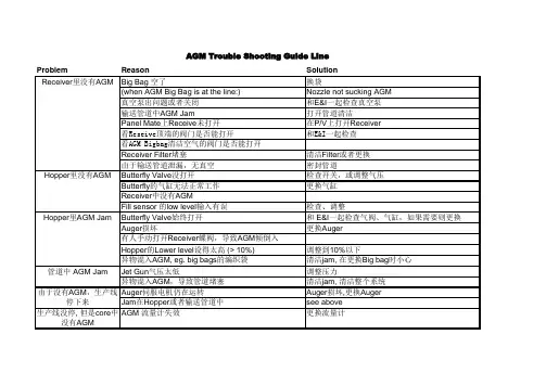
Problem ReasonSolution Big Bag 空了换袋(when AGM Big Bag is at the line:)Nozzle not sucking AGM 真空泵出问题或者关闭和E&I 一起检查真空泵输送管道中AGM Jam打开管道清洁Panel Mate 上Receive 未打开在P/V 上打开Receiver 看Reseive顶端的阀门是否能打开和E&I一起检查看AGM Bigbag清洁空气的阀门是否能打开Receiver Filter 堵塞清洁Filter 或者更换由于输送管道泄漏,无真空密封管道Butterfly Valve 没打开检查开关,或调整气压Butterfly 的气缸无法正常工作更换气缸Receiver 中没有AGMFill sensor 的low level 输入有误检查、调整Butterfly Valve 始终打开和 E&I 一起检查气阀、气缸,如果需要则更换Auger 损坏更换Auger有人手动打开Receiver 蝶阀,导致AGM 倾倒入Hopper 的Lower level 设得太高 (> 10%)调整到10%以下异物混入AGM, eg. big bags 的编织袋清洁jam, 在更换Big bag 时小心Jet Gun 气压太低调整压力异物混入AGM ,导致管道堵塞清洁jam, 清洁整个系统Auger 伺服电机仍在运转Auger 损坏,更换Auger Jam 在Hopper 或者输送管道中see above 生产线没停, 但是core 中没有AGMAGM 流量计失效更换流量计AGM Trouble Shooting Guide Line管道中 AGM Jam Hopper 里AGM Jam Hopper 里没有AGM Receiver 里没有AGM 由于没有AGM ,生产线停下来仅在片的一侧有AGM Jet Gun有问题更换或者修复Jet Gun片中AGM的总量不对调节AGM SetPoint片中AGM分布不正确Jet Gun压力太低调节Core Drum真空不对检查Core Drum真空,是否有网面B/UProblem ReasonBig Bag Station is empty(when AGM Big Bag is at the line:)Vacuum pump is defect or switched off.Jam in the feed pipesReceiver is switched off at the Panel MateCan the Valve on the top of Reciever open?can the Cleaning Air Valve open?Receiver Filter is blockedNo vacuum in feed pipes due to leakageButterfly Valve doesn´t switchAir Cylinder Butterfly is defect.No AGM in ReceiverFill sensor low level has wrong value inputButterfly Valve stays openAuger is brokenSomebody dumped manually the receiver contentsin a full hopperLower level is set too high (> 10%)Jam at the Auger through wrong things in the AGM,eg. parts of the big bags.Pressure of the Jet Gun too lowJam in the Funnel due to wrong parts in the AGM.Auger servo is runningJam in Hopper/ at the FunnelNo Line stop, but AGM is missing in the core AGM Flowmeter defectNo AGM in Hopper Jam in Hopper Jam at the AGMFunnelLine stop: No AGM AGM Trouble Shooting Guide LNo AGM in ReceiverAGM only on one side of the diaper Malmanufactured Jet Gun, due to that fact wrong AGM FlowWrong AGM amount in diaperJet Gun pressure too lowVacuum Core millhouse not on the correct valueWrong AGM Distribution in theDiaperide LineSolutionRefillNozzle not sucking AGMCheck the pump with E&IClean Feed pipesSwitch the Receiver onCheck wih E&ICheck wih E&IExchange Filter (Procedure is discribed below)Seal leakageCheck switch/AdjustmentsExchange Air CylinderCheck adjustment.Check Butterfly Valve with an E&I, check the Air Cylinder, if necessary, exchange them.Exchange AugerAdjust Lower level correctlyClear the jam, be careful at the preparation of the big bags.Adjust PressureClear the jam, clean the system.Auger is broken, exchange Augersee aboveExchange FlowmeterExchange or repair Jet GunAdjust AGM value at the panelmate adjust pressureCheck the system。
![客户园地Trouble_Shooting之AKTA_system[1]](https://uimg.taocdn.com/864ce409eff9aef8941e068f.webp)
【AKTA 纯化设备Trouble Shooting】如果遇到电脑和AKTA仪器无法正常连接,该如何处理?回答:1.CU950状态观察:Power灯不亮或闪烁——电源问题或CU950问题,请先确认电源是否正常,如果电源正常,CU950可能已损坏。
PC与System灯均闪烁——请将电脑和AKTA仪器均关系,再先开启仪器等待5分钟,待其自检结束后,再打开电脑,等待电脑完成启动,再次确认CU950灯状态,如果没有变化,首先从PC着手解决问题。
灯不亮――CU950可能坏了2.物理连接检查,若使用的是USB插口形式,线路重插——需注意:CU950上有三根线,一根电源线,一根USB线(一端的扁平口接电脑,另一端比较方形的接口接CU950),一根网线,网线接口应插在Uninet1口中;另外一种高级连接,是AKTA和电脑之间用网线来联,网络连接的IP地址是192.168.*.*(其地址可以在CU950模块上找到,一共12位数,分4组,前两组一定是192.168.,在安装Unicorn程序时会用到),比USB连接更稳定。
另外,网线选择时,推荐选择交叉头带有屏蔽线的网线(这些要求可以在购买网线时告知卖家)3.电脑问题处理:重启电脑和仪器——先启动AKTA后启动电脑Windows系统――请选择英文正版系统,如果电脑是Win7 professional version操作系统,只能安装Unicorn5.31或更高版本。
检查是否安装杀毒软件——应卸载重装软件——安装前注意提醒客户进行备份4. 排除错误操作――比如驱动没装,strategy选择错误等。
驱动是否安装,可以在硬件管理器中查看,若未安装,会出现黄色问号标识提示;如果Strategy安装错误,查看其设备配置(泵10或100(标在泵头的不锈钢处)或P960样品泵,紫外UV或UPC,收集器),确认应安装哪个策略;如果曾经升级过,收集器必须在Stragety安装时进行勾选,其他的泵或紫外,或Air sensor等的添加则在System administrator的Component里进行勾选。
关于DP中的trouble shooting 目录(一)备份被锁,无法进行(二)磁带位置与IDB记录不一致(三)卡带处理(四)磁带出现fair状态(五)Tape显示NO HW(六)Device is locked(七)ESL322e firmware update(八)Drive超时问题的处理(九) DP中常用命令(十)IDB Export & Import(十一)TableSpace空间不足的相关问题(十二)Media Pool无法打开(十三)Drive abort 无法继续备份(一)备份被锁,无法进行问题现象:启动备份时产生如下错误:问题判定:产生此warning的原因是某个进程退出时没有正常退出而产生一个锁定文件,所以启动备份时不能正常启动。
解决办法:删除该锁定文件后重新启动备份。
Command:rm /var/opt/ignite/locked_file name返回目录(二)磁带位置与IDB记录不一致问题现象:在copy过程中因备份有问题,为了不影响业务重启了DP,重启成功后再重新启动该未完成的COPY任务时,备份中产生如下warning:问题判定:磁带的物理位置与IDB中所记录的不一致。
问题解决:进行barcode scan后重新备份。
返回目录(三)卡带处理问题现象:问题判定:磁带卡在drive里,无法退出。
问题解决:1.用命令将drive里的磁带强行退出-到DP里看带子卡在哪个drive(如10-180-lto的SCSI_1)。
-再到那个drive里,看看他的物理路径(SDSI Address)。
如:bjdcbk01 /dev/rmt/19mn-然后到secureCRT里进入bjdcbk01 , 进入那个带库(omni_lto1)。
-stat d,看看哪个磁带在那个drive里卡着呢(如s31)-到bjdcbk01 , #mt -f /dev/rmt/19mn offline 把磁带用命令导出-然后在进入omni_lto1, move d1 s31.把磁带放回原来的槽位。
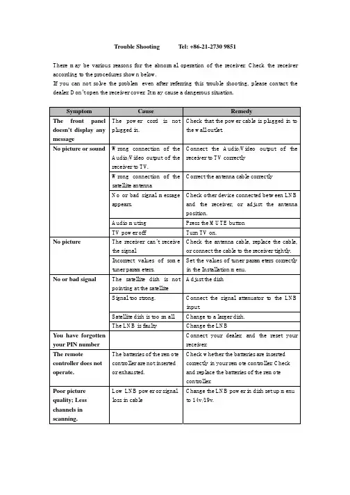
Trouble Shooting Tel: +86-21-2730 9851There may be various reasons for the abnormal operation of the receiver. Check the receiver according to the procedures shown below.If you can not solve the problem even after referring this trouble shooting, please contact the dealer. Don’t open the receiver cover. It may cause a dangerous situation.SymptomCauseRemedyThe front panel doesn’t display any messageThe power cord is not plugged in.Check that the power cable is plugged in tothe wall outlet. Wrong connection of the Audio/Video output of the receiver to TV .Connect the Audio/Video output of the receiver to TV correctly Wrong connection of the satellite antennaCorrect the antenna cable correctly No or bad signal message appears. Check other device connected between LNB and the receiver, or adjust the antennaposition. Audio muting Press the MUTE button No picture or soundTV power offTurn TV on.The receiver can’t receive the signal Check the antenna cable, replace the cable, or connect the cable to the receiver tightly. No pictureIncorrect values of some tuner parameters. Set the values of tuner parameters correctly in the Installation menu.The satellite dish is not pointing at the satellite Adjust the dish Signal too strong. Connect the signal attenuator to the LNBinput.Satellite dish is too small Change to a larger dish. No or bad signalThe LNB is faultyChange the LNBYou have forgotten your PIN number Connect your dealer, and the reset your receiver.The remotecontroller does not operate. The batteries of the remote controller are not inserted or exhausted. Check whether the batteries are inserted correctly in your remote controller. Check and replace the batteries of the remotecontroller. Poor picture quality; Less channels in scanning. Low LNB power or signal loss in cableChange the LNB power in dish set up menu to 14v/19v.。

维修指南Trouble Shooting Guide故障现象Trouble shoot原因Possible Causes处理方法Solutions净水机不制水No of water dispensed from unit 进水阀门未打开Inlet valve is in the off position打开进水阀门Check water connections and supplyvalves进水压力不足(<0.1MPA) Waterpressure is insufficient (<0.1MPA)提高进水压力Check filter lines for kinks and checksupply valve前级滤芯堵塞Pre-filter blockage更新前级滤芯Remove/change Pre-filter unit超滤膜堵塞Ultra filtration membrane clogged更新或清洗(约请专业人员)Replace membrane连接处漏水Junction leakage 普通接头螺帽未拧紧loose connection重新拧紧螺帽Re-connect the fitting过滤器紧固圈未拧紧Filter fastening ring not tightened重新拧紧紧固圈Retighten the clamping ring 净水机密封圈破损Water purifier damaged seals更换密封圈Replace the seals净水有异味Water odor 后置炭滤芯失效Rear charcoal filter failure更换后置炭滤芯Replace the rear charcoal filter长时间未用水Stale waterFlush system out for 5-10 minutes冲洗5-10分钟初装时未按照要求冲洗Flush system prior to initial useFlush system prior to initial use首次使用前冲洗系统净水压力小unsatisfactory waterpressure 供水管道漏水Water supply line leakage and orblockage in filters重新连接或更换漏水的管道(联系专业维修员)replace water lines or contactcustomer service浓水管不排水can not drain system 进水阀门未打开Inlet valve is in the closed position打开进水阀门Open the inlet valve进水Water pressure is insufficient压力不足(<0.1MPA)提高进水压力至所要求Improve water pressure to therequiredPP滤芯堵塞PP filter clogging更换PP滤芯PP filter replacement前、后置活性炭滤芯堵塞更换前、后置活性炭滤芯Front, rear carbon filter clogging Replace post carbon filter 废水比堵塞Wastewater pluggedReplace or clean line浓水管长流水Drain system lineissues 单向阀损坏Valve may be damaged更换或请专业人员维修Replace/repair中空丝膜严重堵塞Fiber membrane清洗或更换(请专业人员)Clean or replace by Professionals。
Troubleshooting Guide- mechanical -X10i, X10a, SO-01BTrouble Shooting Guide Repair Instruction Mechanical/ CONTENTS1 Problem Areas (4)1.1 Power (4)1.1.1 Will not power on or will switch off randomly (4)1.2 Keys (6)1.2.1 Menu Home Back Keys (6)1.2.2 Camera key (7)1.2.3 On/Off key (8)1.2.4 Volume key (9)1.3 Key Illumination (11)1.3.1 Key Illumination (11)1.3.2 Notification (12)1.4 Display (13)1.4.1 Graphics & Illumination (13)1.4.2 Touch Screen malfunction (13)1.5 Audio (15)1.5.1 Microphone (15)1.5.2 Ear Speaker (16)1.5.3 Loudspeaker (17)1.6 Vibrator (19)1.6.1 Vibrator not generating alerts (19)1.7 Camera (20)1.7.1 Camera defects (20)1.8 Flash LED (21)1.8.1 Flash LED defects (21)1.9 Memory Card (22)1.9.1 Memory Card not detected (22)1.10 SIM (23)1.10.1 SIM not detected (23)1.10.2 Incorrect SIM indicated (23)1.11 Bluetooth, W-LAN, GPS (24)1.11.1 Bluetooth, W-LAN, GPS malfunctions (24)1.12 Accelerometer (25)1.12.1 Accelerometer test fails (25)1.13 Sensor (26)1.13.1 Proximity Sensor maulfunctions (26)1.13.2 Light Sensor malfunctions (27)1.14 Real Time Clock (28)1.14.1 Real Time Clock test fails (28)1.15 Charging (29)1.15.1 Battery will not charge (29)1.16 Network & Signal (30)1.16.1 No/Poor signal (30)Trouble Shooting Guide Repair Instruction Mechanical/1.17 HandsFree by Wire (32)1.17.1 Connection to Portable HandsFree fails (32)1.18 Data Communication (34)1.18.1 Data transfer via Micro USB Connector fails (34)2 Revision History (35)Trouble Shooting Guide Repair Instruction Mechanical/Areas1 Problem1.1 Power1.1.1 Will not power on or will switchoff randomlyCheck:Check whether the phone vibrates and the Keyboardilluminates after the power key is depressedAction:If activation of the Vibrator and the Main Key illuminates isdetected, refer to section 1.4 ‘Display’.Check:Inspect the contact pads on the BatteryAction:1. If dirty or oxidized – clean the pads.2. If damaged – replace the Battery.Check:Inspect the Battery ConnectorAction:1. If dirty or oxidized – clean the connector.2. If adhesive is detected on the contact pins, use an eraserto gently rub off the adhesive.3. If damaged –send to higher level of repair.Check:Inspect the Key On/OffAction:1. If dirty or oxidized – clean it.2. If damaged – replace it.Trouble Shooting Guide Repair Instruction Mechanical/ Problem Areas: PowerCheck:Check the connection between the Key On/Off (a) and thedome sheet on the Receiver FPC (b).Action:Reinstall the Key On/Off (a) to ensure the key is properlylocated on the Receiver FPC (b).Check:1. Check the BtB connector of Receiver FPC to the MainPBA2. Inspect the Receiver FPCAction:1. If the BtB connector is not properly connected –disconnect and reconnect it.2. If dirty or oxidized – clean the BtB connector.3. If the Receiver FPC is damaged – replace it.4. Send to higher level of repair.Trouble Shooting Guide Repair Instruction Mechanical/ Problem Areas1.2 Keys1.2.1 Menu Home Back KeysCheck:Inspect the Key MainAction:1. If clogged – clean it.2. If damaged – replace it.Check:Check the connection between the Key Main and the MainKey FPC.Action:Reinstall the Key Main to ensure the key is properly locatedon the Main Key FPC.Check:Check the connection between the Main Key FPC and theMain PBAAction:If the BtB connector is not properly connected – reconnect it.Trouble Shooting Guide Repair Instruction Mechanical/ Problem Areas: KeysCheck:Inspect the Main Key FPCAction:1. If the Main Key FPC is damaged – replace it.2. Send to higher level of repair.1.2.2 Camera keyCheck:Inspect the Key CameraAction:1. If clogged – clean it.2. If damaged – replace it.Check:Check the connection between the Key Camera and theMain Key FPC.Action:Reconnect and reinstall the Key Camera to ensure the KeyCamera is properly located on the dome sheet.Check:Check the connection between the Main Key FPC and theMain PBAAction:If the BtB connector is not properly connected – reconnect it.Trouble Shooting Guide Repair Instruction Mechanical/ Problem Areas: KeysCheck:Inspect the Main Key FPCAction:1. If the Main Key FPC is damaged – replace it.2. Send to higher level of repair.1.2.3 On/Off keyCheck:Inspect the Key On/OffAction:1. If dirty or oxidized – clean it.2. If the Key On/Off is damaged – replace it.Check:Check the connection between the Key On/Off (a) and thedome sheet on the Receiver FPC (b).Action:Reinstall the Key On/Off (a) to ensure the key is properlylocated on the Receiver FPC (b).Check:1. Check the BtB connector of Receiver FPC to the MainPBA2. Inspect the Receiver FPCAction:1. If not properly connected – disconnect and reconnect it.2. If dirty or oxidized – clean the connector.Trouble Shooting Guide Repair Instruction Mechanical/ Problem Areas: Keys3. If the Receiver FPC is damaged – replace it.4. Send to higher level of repair.1.2.4 Volume keyCheck:Inspect the Key VolumeAction:If damaged – replace it.Check:Check the connection between the Key Volume (a) and theReceiver FPC (b).Action:Reinstall the Key Volume (a) to ensure the key is properlylocated on the Receiver FPC (b).Check:1. Check the BtB connector of Receiver FPC to the MainPBA.2. Inspect the Receiver FPCAction:1. If not properly connected – disconnect and reconnect it.2. If dirty or oxidized – clean the connector.Trouble Shooting Guide Repair Instruction Mechanical/ Problem Areas: Keys3. If the Receiver FPC is damaged – replace it.4. Send to higher level of repair.Trouble Shooting Guide Repair Instruction Mechanical/ Problem Areas1.3 Key Illumination1.3.1 Key IlluminationCheck:Inspect the LED from the outside of the phoneAction:1. If clogged – clean it.2. If dirty or oxidized – clean it.Check:Check the BtB connectors on both side of Main Key FPCand Main PBAAction:1. If not properly connected – disconnect and reconnect.2. If dirty or oxidized – clean them.3. If the Main Key FPC (a) is damaged – replace it4. If the Key Main (b) is damaged – replace it.5. Send to higher level of repair.Trouble Shooting Guide Repair Instruction Mechanical/1.3.2 NotificationCheck:Inspect the Notification LED from the outside of the phoneAction:If dirty or oxidized – clean it.Check:Inspect the Notification LED on the Receiver FPCAction:If dirty or oxidized – clean it.Check:Check the BtB connector on both sides of the Receiver FPCand the Main PBAAction:1. If not properly connected – disconnect and reconnect it.2. If dirty or oxidized – clean the connectors.2. Replace the Receiver FPC.3. Send to higher level of repair.Trouble Shooting Guide Repair Instruction Mechanical/ Problem Areas1.4 Display1.4.1 Graphics & IlluminationCheck:Check whether the phone vibrates and the Keyboardilluminates after the power key is depressedAction:If activation of the Vibrator and the Keyboard illumination isnot detected, refer to section 1.1 ‘Power’.Check:The connection between Display and Main PBAAction:1. If not properly connected – disconnect and reconnect.2. If dirty or oxidized – clean both sides of the BtBconnector.3. If the Display is damaged – replace the Display and theAdhesive Frame Sub Assembly.4. Send to higher level of repair.1.4.2 Touch Screen malfunctionRemove Extra Screen Protector attached on Front Coverassy first if have before checking!Check:Check the BtB connectors on both sides on Front CoverAssy and Main PBAAction:1. If not properly connected – disconnect and reconnect.2. If dirty or oxidized – clean it.Trouble Shooting Guide Repair Instruction Mechanical/Remove Extra Screen Protector attached on Front Coverassy first if have before checking!Check:Inspect the Front Cover Assy.Action:1. If damaged – replace it.2. Send to higher level of repair.Trouble Shooting Guide Repair Instruction Mechanical/ Problem Areas1.5 Audio1.5.1 MicrophoneCheck:Inspect the Microphone‘s external from outsideAction:If clogged – clean the port.Check:Inspect the Microphone‘s external portAction:If dirty or oxidized – clean it.Check:Inspect the Microphone‘s mashAction:If damaged – replace the Rear Cover Assy.Check:Inspect the Microphone on the Main PBAAction:1. If dirty or oxidized – clean it.2. Send to higher level of repair.Trouble Shooting Guide Repair Instruction Mechanical/ Problem Areas: Audio1.5.2 Ear SpeakerCheck:Inspect the Ear Speaker‘s external portAction:If clogged – clean it.Check:Check the connection between the Receiver FPC and theMain PBAAction:1. If the BtB connectors are dirty or oxidized – clean them.2. Replace the Receiver FPC.3. Send to higher level of repair.Trouble Shooting Guide Repair Instruction Mechanical/ Problem Areas: Audio1.5.3 LoudspeakerCheck:Inspect the Loudspeaker’s external portAction:If clogged – clean the port.Check:Inspect the Loudspeaker’s mashAction:If damaged – replace the Rear Cover Assy.Check:Inspect the LoudspeakerAction:If dirty or oxidized – clean it.Check:The connection between the SIM and MicroSD FPC and theMain PBAAction:1. If not properly connected – disconnect and reconnect.2. If dirty or oxidized – clean both sides of the BtBconnector.Trouble Shooting Guide Repair Instruction Mechanical/ Problem Areas: AudioCheck:Inspect both sides of the Loudspeaker‘s contact pads andpinsAction:1. If adhesive is detected on the contact pads/pins - use aneraser to gently rub off the adhesive.2. Replace the Non-Celler Antenna Speaker Box.3. Send to higher level of repair.Trouble Shooting Guide Repair Instruction Mechanical/ Problem Areas1.6 Vibrator1.6.1 Vibrator not generating alertsAction:Send to higher level of repairTrouble Shooting Guide Repair Instruction Mechanical/ Problem Areas1.7 Camera1.7.1 Camera defectsCheck:Inspect the camera windowAction:1. If dirty – clean the window.2. If adhesive is detected - use an eraser to gently rub offthe adhesive.3. If scratched or damaged – replace the Rear Cover Assy.Check:Inspect the CameraAction:1. If dirty – clean it.2. If adhesive is detected - use an eraser to gently rub offthe adhesive.3. Replace the Camera 8 MPixel CMOS.4. Send to higher level of repair.Trouble Shooting Guide Repair Instruction Mechanical/ Problem Areas1.8 Flash LED1.8.1 Flash LED defectsCheck:Inspect Flash LED lensAction:If dirty – clean it gently.Check:Inspect Flash LEDAction:If adhesive is detected - use an eraser to gently rub off theadhesive.Check:The connection between the SIM and MicroSD FPC and theMain PBAAction:1. If not properly connected – disconnect and reconnect.2. If dirty or oxidized – clean both sides of the BtBconnector.3. If damaged – replace the SIM and MicroSD FPC and thetwo Conductive Gaskets.4. Send to higher level of repair.Trouble Shooting Guide Repair Instruction Mechanical/ Problem Areas1.9 Memory Card1.9.1 Memory Card not detectedCheck:Inspect the Memory Card holderAction:1. If dirty or oxidized – clean the holder2. If adhesive is detected - use an eraser to gently rub offthe adhesive.Check:The connection between the SIM and MicroSD FPC and theMain PBAAction:1. If not properly connected – disconnect and reconnect.2. If dirty or oxidized – clean both sides of the BtBconnector.Check:Inspect the SIM and MicroSD FPCAction:1. If damaged – replace the SIM and MicroSD FPC and thetwo Conductive Gaskets.2. Send to higher level of repair.Trouble Shooting Guide Repair Instruction Mechanical/ Problem Areas1.10 SIM1.10.1 SIM not detectedCheck:Inspect the SIM Card holderAction:1. If dirty or oxidized – clean the holder2. If adhesive is detected - use an eraser to gently rub offthe adhesive.Check:The connection between the SIM and MicroSD FPC and theMain PBAAction:1. If not properly connected – disconnect and reconnect.2. If dirty or oxidized – clean both sides of the BtBconnector.3. If damaged – replace the SIM and MicroSD FPC and thetwo Conductive Gaskets.4. Send to higher level of repair.1.10.2 Incorrect SIM indicatedCheck:Check whether the phone is locked to a particular operatorand whether the correct operator SIM is being usedAction:1. Use a proper operator SIM or test SIM2. Send to higher level of repairTrouble Shooting Guide Repair Instruction Mechanical/ Problem Areas1.11 Bluetooth, W-LAN, GPS1.11.1 Bluetooth, W-LAN, GPSmalfunctionsAction:Send to higher level of repairTrouble Shooting Guide Repair Instruction Mechanical/ Problem Areas1.12 Accelerometer1.12.1 Accelerometer test failsAction:Send to higher level of repairTrouble Shooting Guide Repair Instruction Mechanical/ Problem Areas1.13 Sensor1.13.1 Proximity SensormaulfunctionsCheck:Check the BtB connector on both sides of the Receiver FPCand the Main PBAAction:1. If not properly connected – disconnect and reconnect it.2. If dirty or oxidized – clean the connector.Check:Inspect the Proximity Sensor on the Receiver FPCAction:1. If dirty or oxidized – clean it.2. Replace the Receiver FPC.3. Send to higher level of repair.Trouble Shooting Guide Repair Instruction Mechanical/ Problem Areas: Sensor1.13.2 Light Sensor malfunctionsCheck:Check the BtB connector on both sides of the Receiver FPCand the Main PBAAction:1. If not properly connected – disconnect and reconnect it.2. If dirty or oxidized – clean the connector.Check:Inspect the Light Sensor on the Receiver FPCAction:1. If dirty or oxidized – clean it.2. Replace the Receiver FPC.3. Send to higher level of repair.Trouble Shooting Guide Repair Instruction Mechanical/ Problem Areas1.14 Real Time Clock1.14.1 Real Time Clock test failsAction:Send to higher level of repairTrouble Shooting Guide Repair Instruction Mechanical/ Problem Areas1.15 Charging1.15.1 Battery will not chargeCheck:Inspect the contact pads of the BatteryAction:1. If dirty or oxidized – clean the pad.2. If damaged – replace the Battery.Check:Inspect the Micro USB connectorAction:If dirty or oxidized – clean the connector.If damaged-send to higher level of repair.Check:Inspect the Battery ConnectorAction:1. If dirty or oxidized – clean the connector.2. If adhesive is detected - use an eraser to gently rub offthe adhesive.3. If damaged – send to higher level of repair.Trouble Shooting Guide Repair Instruction Mechanical/ Problem Areas1.16 Network & Signal1.16.1 No/Poor signalCheck:Ensure that a correct SIM is installedInspect the antenna contact pads/pins on the Main Antennaand the Main PBAAction:1. If dirty or oxidized – clean the pads/ pins.2. If adhesive is detected - use an eraser to gently rub offthe adhesive.3. Replace the Main Antenna.4. Check whether Shield Can Lid A1 is assembled well toconnect Ground.5. If Shield can lid A1 is not well connected to Ground,replace a new one!Follow shield can lid A1 replacement in WI firmly!A. can’t reuse the old shield can lid after disassembly;B .assemble the new shield can lid from Down side;Trouble Shooting Guide Repair Instruction Mechanical/ Problem Areas5. Follow the assembly sequence to press the lid;6. Put a new Shield Can MComp Sheet Lid A1.7. Send to higher level of repairTrouble Shooting Guide Repair Instruction Mechanical/ Problem Areas1.17 HandsFree by Wire1.17.1 Connection to PortableHandsFree failsCheck:Inspect the Audio Jack ConnectorAction:If dirty or oxidized – clean the connector.Check:Check the contact between the Audio Jack Connector andReceiver FPCAction:1. If adhesive is detected - use an eraser to gently rub offthe adhesive.2. If the Audio Jack Connector is damaged – replace it.Check:Check the BtB connector on both sides of the Receiver FPCand the Main PBAAction:1. If not properly connected – disconnect and reconnect it.2. If dirty or oxidized – clean the connector.Trouble Shooting Guide Repair Instruction Mechanical/3. Replace the Receiver FPC.4. Send to higher level of repair.Trouble Shooting Guide Repair Instruction Mechanical/ Problem Areas1.18 Data Communication1.18.1 Data transfer via Micro USBConnector failsMake sure the settings parameter is correct firstly!Drag the Status Bar menu downwards->USB connected->Mount is selected.Check:Inspect the Micro USB connectorAction:1. If dirty or oxidized – clean the connector2. If damaged—Send to higher level of repairTrouble Shooting Guide Repair Instruction Mechanical/History2 RevisionRev. Date Changes / Comments1 2010-Mar-25 Initialrelease2 2010-04-20 updated3 2010-05-31 Add some comments about extra screen protector for chapter 1.4.2 on page13.。
感谢DXY论坛的solonye老师做了这么精彩的东东。
由于大型串联质谱的飞速发展,双向电泳目前已经逐渐让位给其他的各种非胶系统分析手段,但是双向电泳在很长一段时间内仍然会是我们在蛋白质组学领域中不可缺少的一种分析手段。
这个专题希望能够给大家在2D中遇到的一些问题提供一个快速索引,并且共同讨论您在2D中遇到的问题及解决方案!个人进入蛋白质组学领域也有6-7年的时间了,对于双向电泳技术,从最开始的花篮式电泳到2D-IPG-PAGE,再到现在的2D-DIGE技术都比较熟悉。
使用过安玛西亚和伯乐的1向和2向(包括13cm,18cm和24cm的6胶系统),图像分析软件PDQUEST, IMAGEMASTER,以及PE 配套的PROTEIN2000,GE的TYPHOON配套的DECYDER分析软件。
质谱主要接触过MALDI-TOF, MALDI-TOF/TOF, Q-TOF, LC MS/MS。
这个专题主要是一个译本,来自于2D Principles and Methods Handbook中的Trouble shooting 部分, 由原安玛西亚公司, 现在的通用生物公司提供的,我觉得对我在2D中遇到问题时候找出原因非常有用,而园子里所提供的无论是这个版本的中文版还是BIO-RAD的2D指南都没有这个部分的翻译,或者说有少量翻译但是却没有配图片,使得大家同样无法对号入座的来查找自己的电泳中遇到的问题。
加上这段时间发现仍然有很多战友在使用2D这项技术,并且将自己的2D 图谱发上来探讨,所以萌生了重新翻译并且配上图片和自己的点评的念头。
如有错误或者分析的不好的地方望各位战友不吝指出,谢谢!OK, 首先我们来看一张漂亮的双向电泳图,来自于“电泳皇后” Angelika Görg(左下角是与Görg 教授在HUPO ANUAL WORLD CONGRESS 上的合影,为了不迷倒DXY的MM,把自己的脸模糊处理了,^_^)http://www.wzw.tum.de/proteomik/ (Görg实验室的主页,有大量2D相关资料)现象1:没有明显可见的或者分离的好的点可能原因:(平板凝胶模式)IPG胶条在转移到2向SDS的时候放反了,也就是说支撑面贴在了2向上。
01 Dull spots01 斑点(乌点)Alternative terms: Matt patches别名: 消光区域Description: Uniform, clearly defined velvety areas on surface描述: 制品表面上均匀的、清晰可见的绒面状区域Possible causes: 1 Disturbed melt flow in gating system or near gate1.1 Flow fronts with different velocities (with severalgating points)2 Tearing of already solidified outer skin at sharpbends and abrupt changes in wall thickness可能的原因 1 浇注系统中或靠近浇口处出现不规则熔料流1.1 不同速度的流动前锋 (多个浇口)2 急拐弯处和壁厚突变处已固化的外层料被撕裂Remedial actions: 1 Modify gate; start by injecting material slowly,解决的措施then switch to a faster speed1.1 Even out differences in flow front velocities byimproving the balance of the gating system (whereseveral feed points are involved)2 Round off or polish transition zones and abruptchanges in wall thickness in the runner and mould;balance flow front velocities1 修改浇口;采用先慢后快的充模方式1.1 通过均衡流道系统来减少不同流动前锋的速度差(多个浇口)。
Waters CorporationWaters 2690/5 USER& TROUBLESHOOTING GUIDEContents2690/5 TheorySetup procedures. Troubleshooting the 2690/5 User maintenance of the 2690/5Spare Parts2690/5 Theory2690/5 Solvent Management Flow Path2690/5 TheoryThe solvent management system components work together to deliver solvent in the following sequence.1. The accumulator plunger (left plunger) moves forward delivering solvent,while the primary plunger (right plunger) moves backwards filling withsolvent.2. While the accumulator continues to deliver solvent, the primary plungerwaits. The primary pressure transducer then measures the pressure and matches it to the systempressure by moving the primary plunger forward, pre-compressing the solvent.3.When the accumulator plunger reaches the end of its stroke, it slows down and reverses direction.Simultaneously, the primary plunger moves forward delivering solvent.4.While the accumulator plunger moves backwards, the primary plunger moves forward slightlyfaster which allows the primary plunger stroke to both fill the accumulator piston chamber and to deliver solvent to the rest of the systemThis sequence enables the solvent management system to maintain a consistent and pulse-free manner.2690/5 Sample Management System Theory2690/5 Injection CycleThe injection cycle is completed in three steps.1.Isolation of the loop.Valve 1 closes.Needle wash pump turns on.Valve 4 opens.Needle moves into the bottom seal.Valve 3,2 open venting the loop to atmospheric pressure.2.Sample withdrawal.Valve 3 closesNeedle wash pump turns off. Valve 4 closes.Needle moves into the vial.Syringe moves withdrawing sample.Needle moves to the bottom seal.3.Sample injection.Valve 3 opens. Valve 2 closes.Needle moves into the stream.Valve 1 opens. Sample is injected.Syringe moves home. Valve 3 closes2690/5 Sample Management System Purge & Compression Check The purge cycle consists of three parts.1.Purge: Fills the sample loop with new composition of mobile phase replacing theprevious mobile phase and any air bubbles.2.Flush syringe: Fills the syringe with new composition of mobile phase replacing theprevious mobile phase and any air bubbles.pression check: The mobile phase in the injector assembly is compressed to checkfor leaks, the presence of air bubbles and undegassed mobile phase.Priming a New or Dry system using undegassed solvents1.Fill the solvent bottles with Mobile Phase.2. From the Status Page turn the degasser on. *3. Perform a dry prime until solvent flows from each of the four lines.4. Starting with the organic solvent, perform a 3 minute Wet Prime on each line separately at a flowrate of 7.5 mL/min **5. Once all lines are primed, set the flow rate to 0mL/min with the degasser on for 2 minutes.6. Start the flow with the initial conditions of your chromatographic method. Equilibrate with 10column volumes of solvent.7. Check the Pressure Ripple on page two of the Status Page. The ripple should be less than 2% ofthe system pressure. (For system pressures above 1000psi, repeat Wet Prime if the ripple is toohigh)8. After the column is equilibrated, Purge the autosampler. (initial conditions)9. Run samples.Priming an idle system using existing mobile phase1.From the Status Page turn the degasser on.*2. For each line that will be used, starting with the organic solvent, perform a 1.0 minute Wet Primeat a flow rate of 7.5 mL/min. **3. Once all lines are primed, set flow rate to 0mL/min with degasser on for 2 minutes.4. Start the flow with the initial conditions of your chromatographic method. Equilibrate with 10column volumes of solvent.5.Check the Pressure Ripple on page two of the Status Page. The ripple should be less than 2% ofthe system pressure. (for system pressures above 1000psi, repeat Wet Prime if the ripple is toohigh)6.After the column is equilibrated, Purge the autosampler. (initial conditions)7.Run Samples.Priming an idle system changing the mobile phase1.Fill all of the solvent bottles with mobile phase.2.For each line that will be used, starting with the organic solvent, perform a 3 minute Wet Prime ata flow rate of 7.5 mL/min. **3.Once all of the lines are primed, set the flow rate to 0 mL/min with the degasser on for 2 minutes.4.Start the flow with the initial conditions of your chromatographic method. Equilibrate with 10column volumes of solvent.5.Check the Pressure Ripple on page two of the Status Page. The ripple should be less than 2% ofthe system pressure. (for system pressures above 1000psi, repeat wet prime if the pressure is toohigh)6.After the column is equilibrated, Purge the autosampler. (initial conditions)7.Run Samples.Replacing the Needle Wash Frit (as needed or 6 months) Remove all carousels and power off the 2690/5. Reach into the sample compartment and unscrew the lower frit retainer which located under the injector assembly. Remove the frit with a small diameter pick and discard. Wet the replacement frit with methanol and seat it completely within the retainer. Reinstall the lower retainer using a clockwise motion. Screw the retainer in by hand until it is firmly seated.* The degasser should never be left on with no flow for long periods of time. (i.e. overnight)** Caution: To avoid precipitating salts in the Separations Module use an intermediate solvent such as water when you change from buffers to high-organic content solvents.The volume of each solvent line including the vacuum degasser chamber is 7 .5 mL. This volume must be considered when priming the system and changing to a different mobile phase.The degasser can be turned off, the flow rate stopped and the lamp turned off (if controlling the detector through the Alliance) in a Shutdown Method.SETUP PROCEDURESPriming the Seal Wash Pump (when needed)1.Press the Diag screen key in the Main screen. The Diagnostic screen appears.2.Attach the syringe adapter (from the Startup Kit) to the syringe.3.Remove the solvent filter from the plunger seal wash inlet line or remove the plunger seal washwaste line from the waste container. (Either pushing solvent through it or drawing solvent through it can be used to prime the plunger seal wash pump.)4.Fill the syringe with the plunger seal wash solvent* and attach the syringe adapter to the end of theplunger seal wash line or attach the syringe to the end of the plunger seal wash waste line.5.Press the Prime Sealwash Screen key and then press the Start screen key. The plunger seal washprocedure begins. Push on the syringe to push seal wash solution through the system or draw onthe syringe to pull solvent through the plunger seal wash pump.6.When solvent flows out of the plunger seal wash line or into the syringe (the pump will run quieterwhen it is primed) press the Halt screen key.7.Reinstall the solvent filter and place the seal wash inlet line back into the plunger seal washreservoir or place the plunger seal wash waste line back into the waste container. To finish thepriming push the Start screen key again.8.Press Close to return to the diagnostics screen.* Choose a Seal Wash solution that has high solubility with salts and/or buffers used in the mobile phase. (Usually a solution of 80-90% aqueous, 20-10% methanol.)Priming the Needle Wash Pump (daily or weekly)1.Make sure Needle Wash line (Green Line) is in its appropriate bottle.2.Press the Diag screen key in the Main screen. The Diagnostics screen appears.3.Press the Prime NdlWsh screen key. The 30-second needle wash procedure begins. If solventdoes not flow out of the waste line (the yellow line) press the Start Again screen key.* Choose a Needle Wash solution that your sample is soluble in. Buffered solutions or a mobile phase modifier such as TFA are not recommended. If these solutions are necessary they must be flushed from the instrument.TROUBLE SHOOTING THE 2690/52690/5 System Error MessagesMESSAGE ACTION STEPSAccumulator over pressure Locate restriction... guard column / column / inline filter /blocked tubing.Bubble found on intake Wet prime and allow system to sit at zero flow with thedegasser in continuous mode for approx. 10 min. prior tostarting the run. If the flow rate is greater than 1 mL/min.install extended flow inlet tube.Carousel malfunction Cycle power. If message persists call Waters ServiceRepresentative.Carousel Z axis malfunction Cycle power. If message persists call Waters ServiceRepresentative.Compression check failed Solvent not degassed properly. Check for bubble on syringeplunger. Test seal pack and valve 3. Perform appropriatemaintenance.Degasser pressure fault Replace faulty degasser chamber or vacuum pump. CallWaters Service Representative.Lost prime Solvent not degassed properly. Change check valves. If theflow rate is greater than 1 ml/min. install extended flow inlettube.Missing vial The missing vial should be placed in the correct location in thetray.Disable the vial sensor [Main>>Config>>Highlight] “Verifyvial presence" press clear.Call Waters Service Representative.Needle malfunction Check needle wash reservoir. Prime needle wash. Cyclepower. If message persists call Waters ServiceRepresentative.Plunger homing fault Cycle power. Change inline filter. If message persists callWaters Service Representative.Primary transducer range (volts) Call Waters Service Representative.SampleTROUBLE SHOOTING THE 2690/52690/5 System Error MessagesMESSAGE ACTION STEPSSolvent delivery h/w fault Cycle power. If message persists call Waters ServiceRepresentative.Solvent delivery motor lost sync Cycle power. Change inline filter. If message persists callWaters Service Representative.Syringe Movement malfunction Cycle power. If message persists call Waters ServiceRepresentative.System over pressure Locate restriction... guard column / column / inline filter /blocked tubing.System under pressure Connect column. Locate leak. 50 psi is needed to run thesystem.Chromatographic ErrorsSYMPTOMS POSSIBLE CAUSES CORRECTIVE ACTI0N Erratic retention times Air bubble Wet prime the unit. Degas allsolvents.Malfunctioning check valves Clean/ replace check valves.Solvent leak Check all fittings. Replace seals.Chemistry Check mobile phase, column,Gradient Proportioning Valve.Clogged solvent filters Replace filters.Temperature Use column oven.Increased retention times Incorrect flow rate Malfunctioning check valve.Solvent leak.Incorrect Mobile Phase Change solvent.Column Contaminated. Clean/ replace the column.Chromatographic ErrorsSYMPTOMS POSSIBLE CAUSES CORRECTIVE ACTI0N Reduced retention times Incorrect flow rate Change flow rate.Incorrect solvent composition Change composition. Checkgradient proportioning valve.High column temp. Change column temp.Column contamination Clean/ replace column.Solvent not degassed Degas solvent.Reproducibility errors Solvent not degassed Degas solvent.Air in syringe Purge solvent management system.Incompatible vial septa Switch to approved vial and septa.Sample management Contact Waters Servicesystem Representative.Baseline drift Column not equilibrated Equilibrate column.Detector not equilibrated Allow detector to warm up. Timewill vary with wavelength andsensitivity.Solvent contaminated Use fresh solvent.Solvent not properly degassed Degas solvent.Flow/ Pressure fluctuations Prime system. Replace checkvalves, pump seals.Temperature fluctuations Stabilize operating environment.Leaking flow cell Repair leak.Dirty flow cell Clean flow cell.Baseline noise Flow fluctuations Malfunctioning check valve. Leaks,Seals, fittings.Radio frequency noise Eliminate interference.Air in detector Purge detector.Solvent not degassed Degas solvent.Chromatographic ErrorsSYMPTOMS POSSIBLE CAUSES CORRECTIVE ACTI0N Baseline noise Solvents contaminated Use fresh solvents.Column contaminated Clean/ replace column.Dirty flow cell Clean flow cell.Electronic Call Waters ServiceRepresentative.Sensitivity loss Solvent leak Check all fittingsDegraded, contaminated, or Use fresh sample.improperly prepared sample.Column contaminated Clean/ replace column.Loss of column efficiency Clean/ replace column.Leak in flow cell Repair leak.Change in mobile phase Correct mobile phase. (i.e. pH orionic composition)Contaminated solvents Use fresh mobile phase.Dirty flow cell Clean flow cell.Old Lamp Replace lampSplit peaks Needle wash solvent Prime needle wash solvent.Solvent not appropriate forsamples.Column Clean/ Replace column.User maintenance of the 2690/5The power on the 2690/5 should be cycled once a week to perform self-diagnostic and calibration routine.Replacing an Inlet Check Valve Cartridge1.From the Menu screen select [ Diagnostics > Other Tests>Turn GPV off].2.Remove the compression fitting from the check valve housing using a 5/16” wrench.ing a ½” wrench to remove the check valve housing from the manifold.4.Tip the check valve housing upside down to remove the old check valve cartridge.5.Insert the new check valve cartridge into the check valve housing with the arrow or the two holesfacing up.ing a ½” wrench to reinstall the check valve housing to the manifold. (do not over-tighten )ing a 5/16” wrench reconnect the compression tubing to the check valve housing. (to preventover-tightening of the check valve housing, use a ½’’ wrench to prevent the housing from moving)8.Exit out of diagnostics.9.Prime and degas the system.NOTE: Check valve cartridges may be cleaned. Sonicate check valve cartridges in water for 15 minutes and in an appropriate organic solvent for an additional 15 minutes.User maintenance of the 2690/5Replacing the In-Line Filter1. Use a 5/8” wrench and a 5/16” wrench to separate the compression screw on the left side of the in-line filter from the in-line filter inlet housing.2. Use a 5/8” wrench to hold the filter outlet housing while you loosen the inlet housing with another 5/8” wrench.3. Tip the housing upside down to remove the in-line filter element.4. Insert the replacement in-line filter element.5. Reconnect the in-line filter inlet and outlet housing using two 5/8” wrenches.6. Reconnect the compression screw into the inlet housing.7. Inspect connections for leaks.ATTENTION: The in-line filter insert should be replaced every 6 months or whenever a significant increase in back pressure is seen on the system transducer.User maintenance of the 2690/5Replacing Plunger Seals and Face SealsPlunger Seal Replacement1.Press the Diagnostic screen from the Main screen.2.Press the Other Test screen key in the Diagnostics screen.3.Select Head Removal and Replacement from the list.4.Follow the directions that appear in the Head Removal and Replacement screen.5.Remove the plunger seal using the Seal removal tool (P/N WAT039803).6.Wet the seals and the seal opening with methanol.7.Insert the plunger seal using the seal insertion tool (P/N WAT270969).Face Seal Replacement1. Follow directions 1-4 from the plunger seal replacement directions.2.Remove face seals using plastic tweezers.3.Wet the seals and the seal opening with methanol.4.Replace the face seals in the seal openings using a clean flat object.5.Follow the directions that appear in the Head Removal and Replacement screen.6.Prime the system and allow 10 minutes to degas the mobile phase before running the system. NOTE: Plunger seals and face seals should be replaced at the same time.ATTENTION: To avoid damage to the sealing surfaces do not use sharp tools.2690/5 SPARE PARTS Description Part Number2500 µL Syringe WAT077342 250 µL Syringe WAT07310925 µL Syringe WAT077343 Plunger Seals (kit) WAT270938 Face Seals (kit) WAT270939 Check Valve Cartridge (2) WAT270941 High Flow Inlet Tubing WAT2709682 mL Loop WAT096106 200 µL Loop WAT045584 Vials with Preslit Septa 186000307 Total Recovery Vials with Preslit Septa 186000385In-Line Filter Insert WAT088084 Needle Wash Frit (5) 700001318 PerformancePLUS Needle 700001326 Optional Solvent Tray 205000329 Alliance Interactive System Support CD 715000116。
Microsoft iconBelkin iconBluetooth USB Adapter Trouble Shooting Guide1)Why does the Bluetooth icon change colour?The icon changes colour depending on the status of the USB adapter:RED icon no USB adapter detected i.e. not plugged in WHITE icon USB adapter plugged in and functioning correctly GREEN icon Bluetooth connection to another device i.e. PrimeTest 3002) When I try to connect to my PC, the Bluetooth icon turns GREEN but immediately changes back to WHITE.When the Bluetooth USB adapter is installed on a Windows system, configuration data is stored in relation to the Bluetooth services e.g. Bluetooth Serial Port.If you log on to a different account on the same PC, the Bluetooth services configuration information is not available and this will cause the Bluetooth icon to momentarily change to GREEN then back to WHITE.For example, if you are logged onto the PC as a network user when the Bluetooth software is installed and configured and then log on as a stand-alone user, you will experience this problem.There are two solutions:a) Login to the account used when the Bluetooth software was installed andconfigured.b) Configure the Bluetooth software to work with the alternative login by followingthe Bluetooth USB adapter setup guide – Configuring Bluetooth Services.Note: Configuring for an alternative login will not corrupt the configuration created for the previous login.3) Why have I got two icons in my system tray, one White and one Red.Your computer is running Windows XP with Service Pack 2 and Windows Plug and Play has installed its own Bluetooth driver (called Microsoft Bluetooth Enumerator).Windows has created a second (WHITE) icon and has taken control of the USB adapter, however the Windows driver does not allow the USB adapter to function correctly.The Belkin icon has turned RED as Windows has taken control of the USB adapter and is preventing the Belkin software from communicating with the USB adapter.To allow the USB adapter to function correctly we must replace the Microsoft driver with the correct Belkin driver.1)Right click on the My Computer icon on the desktop and select Properties to open the system properties window.2)Click on the Hardware tab and then Device Manager.3) Click on the ‘+’ next to the “Bluetooth Radios” section, you will see the following devices listed.Right click on the “Belkin Bluetooth Adapter” and select “Update Driver”, the hardware wizard will come up on the screen.4) If asked do not connect to windows update to search for software.Select the second option “Install from a list or specific location (Advanced)” and click next.5) On the next screen select the option “Don’t search I will choose the driver to install and click next.6) A list of compatible drivers will be shown, select the “Belkin Bluetooth Device ” which is the Belkin driver and click next.8) The hardware wizard will finish and you will be left with the following in the device manager,9) Close all windows, you will now see in the system tray that the Microsoft Bluetooth Icon has disappeared and the Belkin icon now has a white centre showing its communicating correctly with the device.4) My PC has built in Bluetooth, do I still need to install the Bluetooth USB adapter?You can use your built-in Bluetooth provided it offers Bluetooth Serial Port within it’s services. Refer to the manufacturers documentation supplied with your PC for details on how to configure a Bluetooth serial port.The Belkin Bluetooth USB adapter can be installed alongside your built in Bluetooth should you wish. The Belkin device will co-exist with the built in Bluetooth device. Simply follow the standard installation process and follow the instructions to configure and pair the devices.5) Can I move the Bluetooth USB adapter between USB ports?In principle, the Bluetooth adapter can be moved between USB ports, however it is advisable to leave it in-situ once it is correctly configured and working. This will minimise the risk of Windows corrupting or reconfiguring the installation.6) I have replaced my Bluetooth USB adapter, I have a single white Bluetooth icon, but my PrimeTest 300 no longer talks to my PC?Every Bluetooth device, such as the USB adapter, has a unique Bluetooth ID from which it can be identified. If you replace the USB adapter, the PrimeTest 300 will be trying to talk to the same PC name e.g. “My Laptop” but “My Laptop” now has a new Bluetooth ID.To check that the Bluetooth ID on the USB adapter and that shown on the PrimeTest 300 match:On the PrimeTest 300, press Menu (F4), select configuration, press right arrow, select Bluetooth Favourites and press right arrow. Now select Computer and press Setup (F3) to open the Setup window.This screen shows that the PrimeTest 300 has been paired with “Jims Laptop” which has aBluetooth ID 000A3A5D7031.Right clicking on the Bluetooth icon in thesystem tray and selecting Advanced Configuration opens the Bluetooth configuration window.This shows that the Computer name matches that on the PrimeTest 300The USB adapter has its Bluetooth ID printed on the reverse. Again, this matches the information stored in the PrimeTest 300 Bluetooth Favourites.If you have replaced the USB adapter the Bluetooth ID shown on the PrimeTest 300 display will now be different from that shown on the new adapter. You must add the new USB adapter to your PrimeTest 300 favourites and pair the devices.Note: If you are using the same Computer name, it will already be in your Bluetooth Favourites list. You can use the existing Computer name but you must make sure you select the computer with the correct Bluetooth ID.If you find this confusing you can change the Computer name before you start setting up the new Bluetooth Favourite on the PrimeTest 300. To do this, right click on the Bluetooth system tray icon and selecting Advanced Configuration. When setting up Bluetooth Favourites, the PrimeTest 300 will then find the new Computer name with the new Bluetooth ID.7) License Error MessagesIf either of the messages below appear during the installation it is possible that there is a compatibility problem between the software version and the USB adapter version.The software installation CD lists compatible USB devices on the bottom edge of the printed side of the disk.This CD is software version 1.4.2.11 and is suitable for use with either the F8T001 ver. 2.11 or the F8T003 ver. 2.11.The USB adapter model number and version number are printed on a label on the side of the device. This USB adapter is an F8T003 and it is version 2.11.Note: If the correct software version is not used, the correct icon (WHITE) will appear in the Windows system tray but the PrimeTest 300 will not connect to the USB adapter.8) Error: Unable to start the Bluetooth stack serviceIf you receive the error message shown when your PC is starting up, the Bluetooth software has been unable to load. This is generally caused by a conflict between the Bluetooth software and other applications which run when your PC stars up.This is generally resolved by restarting your PC and waiting for your PC to finish booting up and loading all software which runs on start up before attempting to use the Bluetooth software or any other applications.9) Which Com port is my Bluetooth USB Adaptor?When I try to download to PATGuard, I am asked to select a COM Port. How do I know what to select?Right click on the Bluetooth icon in the system tray and select Advanced Configuration:Select Local Services in the Bluetooth Configuration window. In the far right column for the Bluetooth Serial Port entry you will see COM ‘x’ where ‘x’ is the COM Port number e.g. COM 4.When prompted by PATGuard to select a COM Port number, you can now select the number found in the Bluetooth Configuration.10) When I use Auto Mode there is no egg timer in the Asset Details screen and my PrimeTest does not find my barcode scanner.If Data Entry has been configured for Keypad only the PrimeTest 300 will not attempt to connect to a barcode scanner. If you wish to use a barcode scanner:Press Menu (F4), select User Options, press Right Arrow, select Preferences and press Right Arrow to open the preferences screen.Select the Data Entry field and use the Left/Right arrow to select Barcode.Press OK (F4) to save.Now, when Auto Mode is selected, the PrimeTest 300 will connect to the Barcode Scanner in configured in Bluetooth Favourites.Note: Make sure the Barcode scanner is switched on before attempting to connect.。