中文点阵字库的使用方法(安富莱电子)
- 格式:pdf
- 大小:229.21 KB
- 文档页数:3
一种lvgl使用点阵字库的方法一种lvgl使用点阵字库的方法介绍LVGL是一个开源的嵌入式图形库,提供了丰富的图形用户界面(GUI)功能。
在开发嵌入式设备的过程中,通常需要使用字库来显示文本内容。
本文将介绍一种使用点阵字库在LVGL中显示文本的方法。
选择点阵字库在使用LVGL显示文本之前,首先需要选择适用的点阵字库。
点阵字库是由一系列的点阵字符组成的,每个字符由一定数量的点阵组成,使用这些点阵可以绘制出字符的形状。
可以根据需求选择不同的点阵字库,如宋体、华文楷体等。
准备点阵字库文件选择好点阵字库后,需要准备相关的字库文件。
点阵字库文件通常以字库名称作为文件名,并以扩展名为.bdf或.c的格式保存。
如果字库文件没有提供,可以使用字库生成工具生成对应的字库文件。
导入点阵字库文件在LVGL中导入点阵字库文件非常简单。
可以按照以下步骤进行操作:1.将点阵字库文件复制到LVGL项目的字库文件夹中。
2.在LVGL的配置文件中添加对应的字库文件路径。
3.在代码中引入相关的头文件,并使用lv_font_add()函数将字库添加到LVGL中。
使用点阵字库绘制文本完成点阵字库的导入后,就可以使用它来绘制文本了。
可以按照以下步骤进行操作:1.创建LVGL的文本对象,使用lv_label_create()函数。
2.使用lv_label_set_text()函数设置文本内容。
3.使用lv_label_set_style()函数设置文本的样式,如字体、颜色等。
4.将文本对象添加到LVGL的显示对象中,使用lv_obj_add_child()函数。
示例代码下面是一个简单的示例代码,演示了如何使用点阵字库在LVGL中显示文本:#include "lvgl/"#include "fonts/arial_" // 导入点阵字库文件int main(void) {lv_init();lv_disp_drv_t disp_drv;lv_disp_drv_init(&disp_drv);// 初始化显示设备lv_disp_t *disp = lv_disp_drv_register(&disp_drv);// 注册显示设备lv_obj_t *label = lv_label_create(lv_scr_act(), NUL L);// 创建文本对象lv_label_set_text(label, "Hello LVGL!");// 设置文本内容lv_label_set_style(label, LV_LABEL_STYLE_MAIN, &aria l_16);// 设置文本样式为点阵字库arial_16lv_obj_align(label, NULL, LV_ALIGN_CENTER, 0, 0);// 居中对齐文本对象while (1) {lv_task_handler();// LVGL任务处理}return 0;}总结本文介绍了一种在LVGL中使用点阵字库的方法。
第18章汉字显示方式一(FontCvt的使用)本期教程主要跟大家介绍官方的小工具Font Converter的使用方法,使用官方的字体转换工具,字体的显示效果要比网上那些针对UCGUI设计的字体生成工具好非常多。
4位抗锯齿的显示效果更是非常棒。
在开头先跟大家强调两点,一个是这个字体小工具必须的使用STemWin软件包里面的,SEGGER官网下载的和MDK安装目录里面带的都是评估版,另一点是在教程中我会要求大家将要显示汉字的C文件转换为UTF-8编码,我仅仅是指的将这个显示汉字的C文件转换为UTF-8编码,这点要切记。
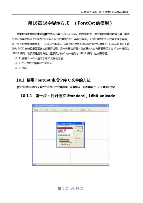
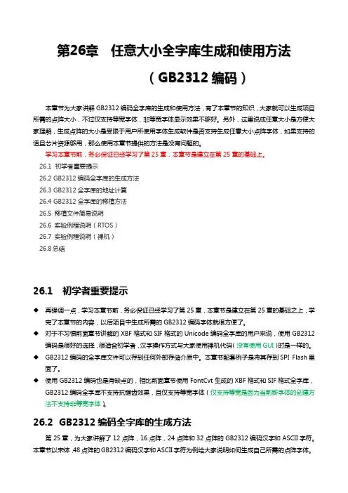
18. 1 使用FontCvt生成字库C文件的方法18. 2 在开发板上面实现中文显示18. 3 总结18.1使用FontCvt生成字库C文件的方法我们先讲如何用这个软件生成部分的汉字数据,这里就以“安富莱电子”五个字进行说明。
18.1.1第一步:打开选择Standard,16bit unicode18.1.2第二步:打开选择字体和字体大小18.1.3第三步:选择禁止所有的字符18.1.4第四步:用unicode软件转换函数用中文转unicode的小软件得到“安福莱电子”这5个字的unicode编码我这里在百度上面找了一个网页应用。
18.1.5第五步:在FontCvt上使能这个五个字的编码在Font Converter软件上面使能这个五个字的unicode编码,以“安”字为例它的unicode编码是5b89,这里有两种办法找这个字。
方法一:直接的在软件里面查找,根据左边的unicode编码。
方法二:通过限制范围查找。
18.1.6第六步:然后点击保存为C文件要将前面的五个字全部找到并使能以后再做保存。
18.2在开发板上面实现中文显示下面我们用18.1小节讲的汉字生成方式生成7中类型的字体。
前三种是Standard的宋体,大小是16,36和72.第四种是144*144点阵的,有没有这么大的字体,需要手动往大小选项里面填写144,并选择右侧的Pixels。

点阵L E D显示原理与点阵汉字库的编码和从标准字库中提取汉字编码的方法-CAL-FENGHAI-(2020YEAR-YICAI)_JINGBIAN点阵LED显示原理与点阵汉字库的编码和从标准字库中提取汉字编码的方法。
2009年06月03日下午 04:27一.实验要求编程实现中英文字符的显示。
二.实验目的1.了解LED点阵显示的基本原理和实现方法。
2.掌握三.实验电路及连线点阵显示模块WTD3088的(红色)列输入线接至内部LED的阴极端,行输入线接至内部LED的阳极端(若阳极端输入为高电平,阴极端输入低电平,则该LED点亮)。
发光点的分布如图22-0所示。
Fig 22-0 WTD3088 LED分布如图22-1示,本实验模块使用74LS374来控制列输入线的电平值。
将74LS374的某输出置0,则对应的LED阴极端被置低。
如图22-2示,本实验模块使用74LS273来控制行输入线,并通过9013提供电流驱动。
将74LS273的某输出置1,则对应的LED阳极端被置高。
每次系统重新开启或总清后,74LS273输出为全0,LED显示被关闭。
通过编程控制各显示点对应LED阳极和阴极端的电平,就可以有效的控制各显示点的亮灭。
Fig 22-1 LED模块及列扫描电路 Fig 22-2 行扫描电路Fig 22-3地址译码电路本实验模块使用4块WTD3088组成16×16点阵,以满足汉字显示的要求。
为了方便的控制四个单元,使用了一片74LS139译码,产生四个地址片选信号:CLKR1= CSLED,CLKR2= CSLED+1,用于行控制的两片74LS273;CLKC1= CSLED+2,CLKC2= CSLED+3,用于列控制的两片74LS374。
实验接线:按示例程序,模块的CSLED接51/96地址的8000H。
四.实验说明使用高亮度LED发光管构成点阵,通过编程控制可以显示中英文字符、图形及视频动态图形。
汉字点阵字库原理一、汉字编码1. 区位码在国标GD2312—80 中规定,所有的国标汉字及符号分配在一个94 行、94 列的方阵中,方阵的每一行称为一个“区”,编号为01 区到94 区,每一列称为一个“位”,编号为01 位到94位,方阵中的每一个汉字和符号所在的区号和位号组合在一起形成的四个阿拉伯数字就是它们的“区位码”。
区位码的前两位是它的区号,后两位是它的位号。
用区位码就可以唯一地确定一个汉字或符号,反过来说,任何一个汉字或符号也都对应着一个唯一的区位码。
汉字“母”字的区位码是3624,表明它在方阵的36 区24 位,问号“?”的区位码为0331,则它在03区3l位。
一级汉字16-55区二级汉字56-87区三级汉字1-9区空闲未用10-15区2. 机内码汉字机内码,又称“汉字ASCII码”,简称“内码”,汉字的机内码是指在计算机中表示一个汉字的编码。
机内码与区位码稍有区别。
如上所述,汉字区位码的区码和位码的取值均在1~94 之间,如直接用区位码作为机内码,就会与基本ASCII码混淆。
为了避免机内码与基本ASCII码的冲突,需要避开基本ASCII码中的控制码(00H~1FH),还需与基本ASCII码中的字符相区别。
为了实现这两点,可以先在区码和位码分别加上20H,在此基础上再加80H(此处“H”表示前两位数字为十六进制数)。
经过这些处理,用机内码表示一个汉字需要占两个字节,分别称为高位字节和低位字节,这两位字节的机内码按如下规则表示:高位字节= 区码+ 20H + 80H(或区码+ A0H)低位字节= 位码+ 20H + 80H(或位码+ AOH)由于汉字的区码与位码的取值范围的十六进制数均为01H~5EH(即十进制的01~94),所以汉字的高位字节与低位字节的取值范围则为A1H~FEH(即十进制的161~254)。
例如,汉字“啊”的区位码为1601,区码和位码分别用十六进制表示即为1001H,它的机内码的高位字节为B0H,低位字节为A1H,机内码就是B0A1H。
我们知道英文字母数量比较少,我们只要用一个字节(8位)就足以表达。
但是汉字非常多。
要怎么表达呢?前人采用的一个方法就是把ASCII码的高128位作为汉字的内码,低128位仍然作为英文字母的内码,然后用两个字节来表示一个汉字。
通过这个内码,我们可以获取汉字的字模信息。
然后再根据这些字模的信息,把相应的汉字显示出来。
二、什么是汉字字库?如何寻址?点阵字库其实就是按照汉字内码的顺序,把汉字的字模信息存起来。
16×16的点阵字库有94区,每个区有94个汉字的字模。
这样总的有94×94个汉字。
我们之前说了,一个汉字由两个ASCII扩展码构成。
第一个ASCII扩展码用来存放汉字的区码,第二个ASCII扩展码用来存放汉字的位码。
具体是这样的:第一个扩展ASCII码= 128 + 汉字的区码第二个扩展ASCII码= 128 +汉字的位码这样,如果我们用char HZ[2]来表示一个汉字。
则:区码= HZ[0] - 128位码= HZ[1] - 128这样,算出区位码之后,我们就可以用它在汉字库里面寻址找字模了。
具体的方式是:该汉字的偏移地址 = (区码-1)×94×一个字占用的字节数+位码×一个字占用的字节数这样我们就很容易的写出显示汉字字模的函数:INT8U *HZK = (INT8U *)0x801c0000; /* 汉字字库的存储地址*/INT8U *ASCII = (INT8U *)0x801fba00; /* ASCII码字库的存储地址 */INT8U const cmp_w[8]={128,64,32,16,8,4,2,1};/********************************************************************************** ************************* Function : DisplayHZ()** Description: 该函数用于在F DGK/GUI上显示一个汉字。
点阵字库HZ K12 H Z K16 H Z K24 ASC12 ASC16 简介及使用方法如何在嵌入式系统中使用大量的汉字和字符呢?DO S前辈们经过艰辛的努力,将制作好的字模放到了一个个标准的库中以免去后辈的麻烦,这就是点阵字库文件。
一般我们使用16*16的点阵宋体字库,所谓16*16,是每一个汉字在纵、横各16点的区域内显示的。
不过后来又有了HZK12、HZK24,HZK32和HZK48字库及黑体、楷体和隶书字库。
虽然汉字库种类繁多,但都是按照区位的顺序排列的。
前一个字节为该汉字的区号,后一个字节为该字的位号。
每一个区记录94个汉字,位号则为该字在该区中的位置。
因此,汉字在汉字库中的具体位置计算公式为:94*(区号-1)+位号-1。
减1是因为数组是以0为开始而区号位号是以1为开始的。
这仅为以汉字为单位该汉字在汉字库中的位置,那么,如何得到以字节为单位得到该汉字在汉字库中的位置呢?只需乘上一个汉字字模占用的字节数即可,即:(94*(区号-1)+位号-1)*一个汉字字模占用字节数,而按每种汉字库的汉字大小不同又会得到不同的结果。
以16*16点阵字库为例,计算公式则为:(94*(区号-1)+(位号-1))*32。
汉字库文该从该位置起的32字节信息即记录了该字的字模信息。
☆打印字库文件和HZK12如果你有UCDOS的HZK24S(宋体)、HZK24K(楷体)或HZK24H(黑体),你还可以使用不同字体的大字模汉字了。
HZK24系列是24*24的点阵字库,每字模占用3*24字节。
如果你按照HZK16的显示方法的话,你会看到......呵呵,字被放倒了。
这是因为该类字库与一般的汉字库不同,这类大字模汉字库是专供打印的打印字库,为了打印的方便将字模都放倒了,你使用时,只要将字模的位信息纵横转置显示即可。
例如你如果定义为mat[24][3]则应该这样输出:f or(i=0;i<24;i++)f or(j=0;j<24;j++)if((0x80>>i%8)&mat[j][i/8])/*转置显示*/putpixel(j+x,y+i,color);还有一类字库HZK12,虽然属于标准字库类型,但如果你将它的字模当作12*12位计算的话,根本无法正常显示汉字。

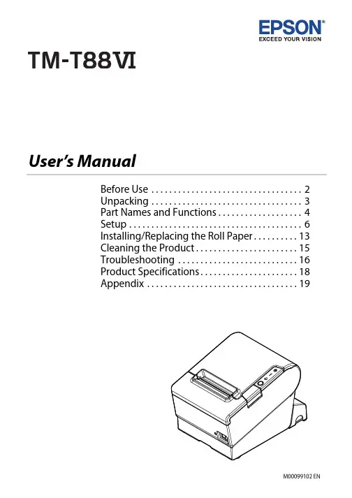
User’s ManualBefore Use . . . . . . . . . . . . . . . . . . . . . . . . . . . . . . . . . . 2Unpacking . . . . . . . . . . . . . . . . . . . . . . . . . . . . . . . . . . 3Part Names and Functions. . . . . . . . . . . . . . . . . . . 4Setup . . . . . . . . . . . . . . . . . . . . . . . . . . . . . . . . . . . . . . . 6Installing/Replacing the Roll Paper. . . . . . . . . . 13Cleaning the Product. . . . . . . . . . . . . . . . . . . . . . . 15Troubleshooting . . . . . . . . . . . . . . . . . . . . . . . . . . . 16Product Specifications. . . . . . . . . . . . . . . . . . . . . . 18Appendix . . . . . . . . . . . . . . . . . . . . . . . . . . . . . . . . . . 19Before UsePlease read this manual carefully before using this product. Keep this manual at hand forimmediate reference whenever necessary. For details about the functions and operation procedure of this product and software, refer to Technical Reference Guide.Safety PrecautionsThe symbols shown below are used in this manual in order to ensure safety and proper use of this product and to prevent danger to customers and other persons, and property damage. The symbols indicate the precaution levels as described below. Be sure that you completely understand their meaning before reading this manual.!WARNING:Handling the product improperly by ignoring this symbol can lead to death or serious injury.!CAUTION:Handling the product improperly by ignoring this symbol can lead to injury and property damage. Q Note:Provides important information and useful tips.Caution LabelsThe caution labels on the product indicate the following precautions.!K CAUTION:Do not touch the thermal head and the frame on its side because it can be very hot after printing. !CAUTION:Touching the manual cutter may cause injury.UnpackingThe following items are included with the standard specification printer.If any item is damaged, contact your dealer.❏Printer❑Roll paper❏Connector cover❑Bottom cover for Connector cover ❏Roll paper guide❑Power switch cover❏Screws❑AC adapter*❏AC cable*❑Setup Guide❏TM-T88VI Software & Documents Disc** May not be included depending on the printer model.Part Names and FunctionsNFC device, bring the device close to this mark. For details on functions that use the NFC tag, see the Technical Reference Guide.2Roll paper coverOpen this cover to install/replace the roll paper.3Manual cutterUse this cutter when you cut the roll paper manually.4Cutter coverOpen this cover to unlock the autocutter blade when the roll paper cover does not open due to apaper jam.5Power switchUse this switch to turn on or off the printer.cover6 ConnectorUse the printer with this cover attached to protect cables.7Cover open buttonUse this button to open the roll paper cover.8Dip switch coverOpen the cover to view the dip switches for communication settings. Do not change the DIP switch settings.Control Panel1(Power) LEDThis LED is on when the printer is on.2(Error) LEDThis indicates an error.3(Paper) LEDOn indicates a paper near end or out. Flashing indicates standby.4Feed buttonPress this button once to feed the roll paper for one line. Hold down this button to continue feeding the roll paper.1234SetupInstalling the Printer Horizontally or VerticallyYou can install the printer horizontally on a flat surface (with the paper exit on top) or vertically ona wall (with the paper exit at the front). For the vertical installation, the optional WH-10 hangingbracket set is necessary.!WARNING:When hanging the printer on the wall with the hanging bracket set, be sure to attach a connector cover to the printer.Setting Up the PrinterTo set up the printer, follow the steps below.1.Connect the cables.2.Attach the connector cover.3.Arrange the cables.4.Install the roll paper.Connecting the Cables!CAUTION:❏For a serial interface, use a null modem cable.❏For a parallel interface, use an IEEE 1284 cable.Q Note:The available interfaces vary by the printer model.1.Make sure the printer is turned off.2.Connect the AC adapter and each interface cable to the connectors on the printer back. For theshape of each connector, see the illustration below.3.Connect the interface cable to the computer.4.Connect the AC cable plug to a power outlet.Attaching the Connector CoverFollow the steps below to attach the connector cover to protect the cables.1.Turn over the printer.2.Position the two hooks on both sides of the connector cover so that they hook the printer case.3.Push the connector cover down to click onto the printer case.HookQ Note:❏You can use the enclosed screw to fix the connector cover.❏To remove the connector cover, turn the printer over, remove the screw, and push the connector cover down while pushing both sides of the connector cover inward to detach the hooks from the printer case.Arranging the CablesPass the cables through cable exits in the connector cover.Some cables can be routed out from the front by passing them through the notch in the printer bottom.If you want to pass the USB cable through the cable exit on the back, fit the cable under the hook on the printer to prevent the cable from coming off.Q Note:You can also attach bottom cover to hide connectors.After the cable arrangement, turn over the printer, and make sure the cables are not pinched.Attaching the Power Switch CoverBy attaching the power switch cover, you can prevent accidental operations of the power switch.You can turn on and off the power switch by inserting a sharp-pointed object in the holes on the power switch cover. To detach the cover, use a sharp-pointed object.To use this cover, install it as shown in the illustration below.!WARNING:If an accident occurs with the power switch cover attached, unplug the power cordimmediately. Continued use may cause fire or shock.Changing the Paper WidthYou can change the paper width from 80 mm to 58 mm by installing the roll paper guide. Follow the steps below to change the paper width.1.Turn off the printer.2.Open the roll paper cover.3.Install the roll paper guide so that the protrusion on the roll paper holder is aligned with thehole on the printer.Q Note:You can use the enclosed screw to fix the roll paper guide.4.Install the roll paper correctly.5.Close the roll paper cover.!CAUTION:❏If you once use the printer with 58 mm paper roll, you cannot change it back to 80 mm.❏You need to set with the memory switch (customized values) for the paper width in Software Setting mode. For information about the memory switch, see the Technical Reference Guide.Installing/Replacing the Roll Paper Follow the steps below to install and replace the roll paper.1.Open the roll paper cover.2.Remove the used roll paper core if any.3.Install the roll paper in the correct direction.4.Pull out some paper, and close the roll paper cover.5.Tear off the paper.Cleaning the ProductCleaning the Printer CaseBe sure to turn off the printer, and wipe the dirt off the printer case with a dry cloth or a damp cloth.!CAUTION:Never clean the product with alcohol, benzine, thinner, or other such solvents. Doing so maydamage or break the parts made of plastic and rubber.Cleaning the Thermal Head and the Platen RollerEpson recommends cleaning the thermal head to maintain receipt print quality. We recommend cleaning periodically (about once every 3 months).Depending on the roll paper used, paper dust may stick to the platen roller and the paper may not be fed correctly. To remove the paper dust, clean the platen roller with a cotton swab moistened with water. Turn on the product power only after the water has completely dried.!K CAUTION:❏After printing, the thermal head and its surroundings (indicated in the circle in illustration below) can be very hot. Be careful not to touch it and to let it cool before you clean it.❏Do not damage the thermal head by touching it with your fingers or any hard object.1.Turn off the printer.2.Open the roll paper cover.3.Clean the thermal elements of the thermal head and the platen roller with a cotton swabmoistened with an alcohol solvent (ethanol or IPA).a. thermal headb. platen rollerTroubleshootingNo lights on the control panelCheck whether the power supply cable is correctly connected to the printer and the socket.(Error) LED on with no printing❏Check whether the roll paper cover is closed. If it is open, close the cover.❏If the (Paper) LED is on, check whether the roll paper is correctly installed and any roll paper remains.(Error) LED flashing with no printing❏Check whether a paper jam has occurred. If paper is jammed, remove the jammed paper referring to the description below and install the roll paper correctly.❏Printing stops if the head overheats and resumes automatically when it cools.❏For other cases, turn the printer off, and after 10 seconds, turn the printer back on. Removing Jammed PaperWhen a paper jam occurs, never pull out the paper forcibly. Open the roll paper cover and remove the jammed paper.!K CAUTION:Do not touch the thermal head and the frame around it (indicated in the circle in the illustration below) because it can be very hot after printing.If the roll paper cover does not open, follow the steps below.1.Turn off the printer.2.Slide the cutter cover toward the front to open it.3.Turn the knob until you see a triangle in the opening. This returns the cutter blade to the normal position. There is a label near the cutter to assist you.a. knobb. triangle4.Close the cutter cover.5.Open the roll paper cover and remove the jammed paper.Product Specifications*1: The available interfaces vary by the printer model.*2: Be sure to use a safety-standards-applied power source that meets the following specifications.Rated output: 24 V/2.0 A - 10.0 A, Maximum output: 240 VA or less*3: This is the average power under our operation conditions. It varies depending on the conditions of use and the model.Printing methodThermal line printing Roll paper Paper width80 mm paper width setting: 79.5 mm ± 0.5 mm {3.13" ± 0.02"} 58 mm paper width setting: 57.5 mm ± 0.5 mm {2.26" ± 0.02"} External diameterMaximum 83 mm {3.27"}Core internaldiameter12 mm {0.47"}Core externaldiameter 18 mm {0.71"}Interface *1Serial: RS-232Parallel: IEEE1284Ethernet: 10BASE-T/100BASE-TXWireless LAN: Connect the optional Wireless LAN unit to the USBconnector.Bluetooth ®: Bluetooth 3.0 (EDR supported)USB: USB 2.0 Full-speed (12 Mbps)USB PlusPower: Full-speed (12 Mbps)Supply voltage *2DC + 24 V ± 7%Current consumption 1.8 AAC power consumption *3 (100 V to 230 V/50 to 60 Hz)Operating:Approx. 30.8 WStandby:Approx. 0.8 WTemperature Operating: 5 to 45°C {41 to 113°F}Storage:–10 to 50°C {14 to 122°F}, except for paperHumidity Operating:10 to 90% RHStorage:10 to 90% RH, except for paperOverall dimensions 148 × 145 × 195 mm {5.83 × 5.71 × 7.68"} (H × W × D)Weight (mass)Approx. 1.6 kg {3.5 lb}AppendixDownloading Drivers, Utilities, and ManualsThe latest versions of drivers, utilities, and manuals can be downloaded from one of the following URLs.For customers in North America, go to the following web site:/support/For customers in other countries, go to the following web site:https:///?service=posRestriction of UseWhen this product is used for applications requiring high reliability/safety, such as transportation devices related to aviation, rail, marine, automotive, etc.; disaster prevention devices; various safety devices, etc.; or functional/precision devices, etc.; you should use this product only after giving consideration to including fail-safes and redundancies into your design to maintain safety and total system reliability. Because this product was not intended for use in applications requiringextremely high reliability/safety, such as aerospace equipment, main communication equipment, nuclear power control equipment, or medical equipment related to direct medical care, etc., please make your own judgment on this product’s suitability after a full evaluation. Precautions When Installing the Power Supply CoverA description of EMI standards is on the bottom of the printer. When the optional power supplycover (OT-BXxxx) is installed, it is hard to check it. In such case, uninstall the power supply cover if necessary.TrademarkEPSON is a registered trademark of Seiko Epson Corporation. Exceed Your Vision is a registered trademark or trademark of Seiko Epson Corporation.The Bluetooth® word mark and logos are registered trademarks owned by Bluetooth SIG, Inc. and any use of such marks by Seiko Epson Corporation is under license.All other trademarks are the property of their respective owners and used for identification purpose only.NotesNo part of this publication may be reproduced, stored in a retrieval system, or transmitted in any form or by any means, electronic, mechanical, photocopying, recording, or otherwise, without the prior written permission of Seiko Epson Corporation. No patent liability is assumed with respect to the use of the information contained herein. While every precaution has been taken in thepreparation of this book, Seiko Epson Corporation assumes no responsibility for errors oromissions. Neither is any liability assumed for damages resulting from the use of the information contained herein.Neither Seiko Epson Corporation nor its affiliates shall be liable to the purchaser of this product or third parties for damages, losses, costs, or expenses incurred by purchaser or third parties as a result of: accident, misuse, or abuse of this product or unauthorized modifications, repairs, or alterations to this product, or (excluding the U.S.) failure to strictly comply with Seiko Epson Corporation’s operating and maintenance instructions.Seiko Epson Corporation shall not be liable against any damages or problems arising from the use of any options or any consumable products other than those designated as Original Epson Products or Epson Approved Products by Seiko Epson Corporation.NOTICE: The contents of this manual are subject to change without notice.©Seiko Epson Corporation 2016-2018. All rights reserved.。
中文字库液晶显示模块使用手册一、液晶显示模块概述1. 液晶显示模块是128×64点阵的汉字图形型液晶显示模块,可显示汉字及图形,内置8192个中文汉字(16X16点阵)、128个字符(8X16点阵)及64X256点阵显示RAM(GDRAM)。
可与CPU直接接口,提供两种界面来连接微处理机:8-位并行及串行两种连接方式。
具有多种功能:光标显示、画面移位、睡眠模式等。
2. 外观尺寸:93×70×12.5mm3. 视域尺寸:73×39mm外形尺寸图二、模块引脚说明128X64 引脚说明引脚名称 方向 说明 引脚名称 方向 说明1 VSS - GND(0V) 11 DB4 I 数据42 VDD - Supply Voltage For Logic (+3.3v) 12 DB5 I 数据53 VO - Supply Voltage For LCD (悬空)13 DB6 I 数据64 RS (CS) O H: Data L: Instruction Code 14 DB7 I 数据75 R/W (SID) O H: Read L: Write15 PSB O H: Parallel Mode L: Serial Mode6 E (SCLK) O Enable Signal16 NC - 空脚7 DB0 I 数据0 17 /RST O Reset Signal 低电平有效8 DB1 I 数据1 18 NC - 空脚9 DB2 I 数据2 19 LEDA - 背光源负极(LED-OV)10 DB3 I 数据3 20 LEDK - 背光源正极(LED+5v) 外形尺寸ITEM NOMINAL DIMEN UNIT模块体积 93×78×12.5 mm视域 70.7×38.8 mm行列点阵数 128×64 dots点距离 0.52×0.52mm 点大小 0.48×0.48 mm三、液晶硬件接口1、逻辑工作电压(VDD):4.5~5.5V2、电源地(GND):0V3、工作温度(Ta):0~60℃(常温) / -20~75℃(宽温)4、电气特性见附图1 外部连接图(参考附图2)模块有并行和串行两种连接方法(时序如下): 1、8位并行连接时序图MPU 写资料到模块RSR/WEDB0-DB7MPU从模块读出资料RSR/WE2、串行连接时序图四、用户指令集指令表—2:(RE=1:扩充指令集)设定绘图0 0 1 AC6 AC5 AC4 AC3AC2AC1AC0设定CGRAM地址到地址计数器(AC)72us RAM地址HS12864-12串口接线方式:备注:1、当模块在接受指令前,微处理顺必须先确认模块内部处于非忙碌状态,即读取BF标志时BF需为0,方可接受新的指令;如果在送出一个指令前并不检查BF标志,那么在前一个指令和这个指令中间必须延迟一段较长的时间,即是等待前一个指令确实执行完成,指令执行的时间请参考指令表中的个别指令说明。
点阵模块使用说明书1. 简介点阵模块是一种常见的显示设备,它由许多小LED灯组成的阵列构成。
每个LED灯可以独立控制,从而实现文字、图案、数字等的显示。
该使用说明书旨在帮助用户了解如何正确使用点阵模块,并提供一些基本操作指南。
2. 规格和参数在使用点阵模块之前,了解其规格和参数是很重要的。
以下是一些常见的规格和参数:- 尺寸:点阵模块的尺寸通常以像素为单位表示,例如8x8,16x16等。
- 电压:点阵模块的工作电压通常在3.3V到5V之间。
- 接口:点阵模块通常使用数字接口(如SPI、I2C)进行控制。
- 显示颜色:有些点阵模块只能显示单色(如红色或绿色),而其他模块可以显示多种颜色。
- 亮度和调节:有些点阵模块允许用户调节亮度和对比度。
3. 连接和控制使用点阵模块之前,首先需要将其连接到您的主控制器(如Arduino、树莓派)或开发板上。
通常,点阵模块会有一组引脚,您需要将其正确连接到相应的引脚上。
连接完成后,您可以使用适当的库或代码来控制点阵模块。
这些库和代码通常可以从开发平台的官方网站或第三方资源库中获取。
在编写代码时,您需要了解点阵模块的接口和操作命令,以正确地控制其显示。
4. 显示文本和图形一旦您成功地连接并控制了点阵模块,您就可以开始显示文本和图形了。
点阵模块通常允许您以像素为单位控制每个LED灯的状态。
通过控制特定的LED灯,您可以在点阵模块上显示所需的文本、图案或数字。
对于文本显示,您需要从字库中选择适当的字符,并使用适当的函数将其显示在点阵模块上。
您可以通过更改LED灯的状态来控制每个像素的亮度和颜色,从而实现更多复杂的显示效果。
5. 实时更新和动画效果除了静态文本和图形之外,点阵模块还允许您实时更新显示内容,并创建动画效果。
通过不断更新点阵模块的状态,您可以实现滚动文本、闪烁效果和动态图像等。
实时更新和动画效果的实现取决于您的控制代码和刷新速率。
您可以使用循环和延迟函数来控制点阵模块的刷新速度,从而实现所需的动画效果。
FYD12864液晶中文显示模块(一) (一)概述 (3)(二)(二)外形尺寸1 方框图 (3)2 外型尺寸图 (4)(三)(三)模块的接口 (4)(四)(四)硬件说明 (5)(五) 指令说明 (7)(五)(五)读写操作时序 (8)(六)(六)交流参数 (11)(七)(七)软件初始化过程 (12)(八)(八)应用举例 (13)(九)(九)附录1半宽字符表 (20)2 汉字字符表 (21)一、概述FYD12864-0402B是一种具有4位/8位并行、2线或3线串行多种接口方式,内部含有国标一级、二级简体中文字库的点阵图形液晶显示模块;其显示分辨率为128×64, 内置8192个16*16点汉字,和128个16*8点ASCII字符集.利用该模块灵活的接口方式和简单、方便的操作指令,可构成全中文人机交互图形界面。
可以显示8×4行16×16点阵的汉字. 也可完成图形显示.低电压低功耗是其又一显著特点。
由该模块构成的液晶显示方案与同类型的图形点阵液晶显示模块相比,不论硬件电路结构或显示程序都要简洁得多,且该模块的价格也略低于相同点阵的图形液晶模块。
基本特性:●●低电源电压(VDD:+3.0--+5.5V)●●显示分辨率:128×64点●●内置汉字字库,提供8192个16×16点阵汉字(简繁体可选)●●内置 128个16×8点阵字符●●2MHZ时钟频率●●显示方式:STN、半透、正显●●驱动方式:1/32DUTY,1/5BIAS●●视角方向:6点●●背光方式:侧部高亮白色LED,功耗仅为普通LED的1/5—1/10 ●●通讯方式:串行、并口可选●●内置DC-DC转换电路,无需外加负压●●无需片选信号,简化软件设计●●工作温度: 0℃ - +55℃ ,存储温度: -20℃ - +60℃二、方框图3、外形尺寸图三、模块接口说明*注释1:如在实际应用中仅使用串口通讯模式,可将PSB接固定低电平,也可以将模块上的J8和“GND”用焊锡短接。
点阵字库一. 什么是点阵字库?我们先了解什么是点阵,简单的说,点阵就是一幅位图。
一般默认都指单色位图,即它是用一个bit表示一个点(像素);其实还有灰阶点阵字库(抗锯齿)和彩色点阵字库(绚丽,但不实用),即多个bit表示一个点(像素)。
点阵字库是指多个(>=1)字符的点阵信息的集合,亦可理解为位图组合。
二. 编码格式目前主要分内码字库和Unicode字库。
(之前项目中应用的是GBK的内码字库,如果要显示日文则无能为力了,目前引入了UNICODE的点阵字库,解决了多语言显示的问题。
)三. 存储格式目前主要分为“Not Fixed” 和“Height Fixed”。
Not Fixed:自适应宽高。
Height Fixed:等高非等宽。
Not Fixed Height Fixed四. 输出格式输出格式是将字符点阵信息以不同的方式存放,反应给用户。
(目前修改使用的是bin输出格式,当然这是指个名字)五.增加日语等多国语言显示工作流程六.字库生成工具及示例步骤说明:如上图示,分5 步。
1. 选择矢量字库文件(*.ttf)或bdf 格式文件(.bdf).A.先将c:\windows\fonts 目录下的字体文件拷贝(ctrl+c)出来,然后本软件即可选择。
B.建议去网上找一个ArialUni.ttf 字库下载地址:/f/4942778.html2. 选择编码格式,转换模式,字体大小,DPI.3. 选择需要支持的字符集。
4. 设置输出文件类型,及输出路径。
5. 点击build 按钮,转换生成字库。
补充说明:A.若您选择的是MBCS 编码格式,则会根据您选择的字符集数产生相应份数的上述文件。
B.若您选择的是UNICODE 编码格式,不论您选多少个字符集,都只会输出一份上述文件。
C.若生成字库失败,则有可能您选择的字体文件(*.TTF)原本就不包含该字符集的字符信息。
比如:宋体中不存在韩文字符,即用宋体生成的字库无法支持韩文显示。
点阵汉字原理与应用一.汉字的编码由于在电脑中,所有的数据都是以0和1保存的。
因此,想要用计算机来显示汉字前提就是要将汉字以二进制,即0和1形式进行编码。
GBK内码在英文的显示操作中,一个字母、数字及字符均由1个ASCII码表示,并且由于英文字符种类相对较少,故其ASCII码是小于等于127的。
而汉字由于种类繁多,每个汉字有2个ASCII码构成,这两个ASCII码称为汉字的GBK内码,通常用十六进制表示。
例如,“啊”的GBK内码=B0 A1。
汉字的GBK内码一定大于A0H,即160,目的是为了防止与英文的ASCII码产生冲突。
区位码为了使每一个汉字有一个全国统一的代码,1980年,我国颁布了第一个汉字编码的国家标准:GB2312-80《信息交换用汉字编码字符集》基本集,这个字符集是我国中文信息处理技术的发展基础,也是目前国内所有汉字系统的统一标准。
由于国标码是四位十六进制,如汉字的GBK内码,为了便于交流,大家常用的是四位十进制的区位码。
所有的国标汉字与符号组成一个94×94的矩阵(见图1所示)。
在此方阵中,每一行称为一个"区",每一列称为一个"位",因此,这个方阵实际上组成了一个有94个区(区号分别为0 1到94)、每个区内有94个位(位号分别为01到94)的汉字字符集。
一个汉字所在的区号和位号简单地组合在一起就构成了该汉字的"区位码"。
区位码和GBK内码之间可以相互转换,区位码=GBK内码-A0H。
例如:“啊”的GBK内码=B0 A1,则其区码=B0-A0=10H=16,而其位码=A1-A0=01,所以“啊”的区位码=16 01,为4位十进制码。
在区位码中,01-09区为682个特殊字符,16~87区为汉字区,包含6763个汉字。
其中16-55区为一级汉字(3755个最常用的汉字,按拼音字母的次序排列),56-87区为二级汉字(3008个汉字,按部首次序排列)。
如何在嵌入式系统中使用大量的汉字和字符呢?DOS前辈们经过艰辛的努力,将制作好的字模放到了一个个标准的库中以免去后辈的麻烦,这就是点阵字库文件。
一般我们使用16*16的点阵宋体字库,所谓16*16,是每一个汉字在纵、横各16点的区域内显示的。
不过后来又有了HZK12、HZK24,HZK32和HZK48字库及黑体、楷体和隶书字库。
虽然汉字库种类繁多,但都是按照区位的顺序排列的。
前一个字节为该汉字的区号,后一个字节为该字的位号。
每一个区记录94个汉字,位号则为该字在该区中的位置。
因此,汉字在汉字库中的具体位置计算公式为:94*(区号-1)+位号-1。
减1是因为数组是以0为开始而区号位号是以1为开始的。
这仅为以汉字为单位该汉字在汉字库中的位置,那么,如何得到以字节为单位得到该汉字在汉字库中的位置呢?只需乘上一个汉字字模占用的字节数即可,即:(94*(区号-1)+位号-1)*一个汉字字模占用字节数,而按每种汉字库的汉字大小不同又会得到不同的结果。
以16*16点阵字库为例,计算公式则为:(94*(区号-1)+(位号-1))*32。
汉字库文该从该位置起的32字节信息即记录了该字的字模信息。
☆打印字库文件和HZK12如果你有UCDOS的HZK24S(宋体)、HZK24K(楷体)或HZK24H(黑体),你还可以使用不同字体的大字模汉字了。
HZK24系列是24*24的点阵字库,每字模占用3*24字节。
如果你按照HZK16的显示方法的话,你会看到......呵呵,字被放倒了。
这是因为该类字库与一般的汉字库不同,这类大字模汉字库是专供打印的打印字库,为了打印的方便将字模都放倒了,你使用时,只要将字模的位信息纵横转置显示即可。
例如你如果定义为mat[24][3]则应该这样输出:for(i=0;i<24;i++)for(j=0;j<24;j++)if((0x80>>i%8)&mat[j][i/8])/*转置显示*/putpixel(j+x,y+i,color);还有一类字库HZK12,虽然属于标准字库类型,但如果你将它的字模当作12*12位计算的话,根本无法正常显示汉字。
怎样使用点阵字库(转)前不久,在网上看到一个生成点阵字的网站.觉得很有意思!到底什么是点阵字,点阵字和字模之间有什么关系?让我们先看一个点阵汉字和一个英文字母:这就是点阵字,也就是根据字符的字模用符号画出来的,当然你可以把*号#号改成其它的任何符号都可以.是不是觉得很有意思了?汉字内码:我们都知道,英文只有少数的几十个字符,在计算机中用一个字节可以很容易的表示出来(也就是ASCII码);而汉字由于结构本身的原因,数量很大,常用的也有几千个.显然计算机中按照英文字符的方式对处理汉字是不可取的.由是前人们就将ASCII表的高128位很少用到的数值以两个为一组来表示汉字,这就是汉字的内码.而剩下的低128位则留给英文字符使用,即英文的内码.看一个C程序示例:程序代码main ( )unsigned char * s , * e = "A" , * c = "王" ;clrscr ( ) ;printf ( "English char =" ) ;s = e ;while ( * s ! = 0 )printf ( "=," , * s ) ;s + + ;printf ( "\nChinease char=" ) ;s = c ;while ( * s ! = 0 )printf ( "=," , * s ) ;s + + ;getch ( ) ;编译运行以后,输出的结果为:English char = 65,Chinease char= 205,245,查ASCII码字符表,很容易得到A的ASCII码为65.我们可以查ASCII码表,得到出ASCII码对应的字符,那我们有什么办法来知道一个汉字内码对应的汉字了?让我们先来认识一下区位码:1981 年5月,我国国家标准总局颁布了《信息交换用汉字编码字符集》(GB2312-80),简称国家标准汉字编码,也叫国标码.国标码共收进标准字符7445 个.其中一级汉字3755个,二级汉字3008个,共计6763个汉字. 由于汉字的字符多,一个字节(即8位二进制代码)不足以表示所有的常用汉字.汉字国标码的每个汉字或符号在计算机中都使用2个字节(16位二进制)代码来表示.在GB2312-80代码表中,纵向分为0~93,共94行.将行号称为区号,列号称为位号,分别有94个区和94个位.区号和位号用十进制表示,不足两位前面补0.这样每个汉字或符号都可用4位十进制表示.这就是我们常说的区位码.每一区共有94个汉字,而位记录该汉字在该区中的具体位置.(记得我们以前读书的时候,报考计算机考试,填写姓名都要我们用区位码填,我们都拿着自己的姓名一个个去查,我们查的那个东东就是区位码.现在想想, 真是心寒呀.还好,我后来就没有查了,弄了个excel的宏.把班上人的姓名全部放到一个excel中,然后一点鼠标,哈哈…… 区位码全自动出来了).现在我们知道,可以从区位码得到汉字,也可以从汉字反查出区位码.那么我们如何从内码得到区位吗?汉字内码与区位码之间有一个简单的数学关系:内码高字节 = 区码+A0H = 区码+160内码低字节 = 位码+A0H = 区码+160这个转换关系,我也不清楚原因,有谁知道还望指点.网上的大师们说这样转换,咱们就这样转换吧.我们刚刚输出"王"的内码为:205(高字节),245(低字节).由上面的换算关系,可以得到"王"字的区位码为:区码=205-160=45位码=245-160=85查一下区位码表,4585所表示的汉字正好是"王".也可以打开输入法,选择内码输入法,然后选择区位码,输入4585,就会输出"王"字.汉字字模:现在让我们来认识一下什么是字模,所谓字模就是是汉字(或者字符)的形态.字模中保存了汉字的点阵信息,记录组成一个字符的点在何处显示,在何处不显示.我们只要得到汉字的字模,我们就可以很容易的程序来控制,把这个字符画出来.我们刚刚得到的仅仅是汉字的内码,并根据汉字内码得到区位码,由区位码查表得到汉字.那么我们如何来得到汉字的字模了?用过UCDOS(或者CCDOS,估计现在只有少数人还知道UCDOS是什么东东)的人应该知道,通过UCDOS可以让DOS系统下正确的显示中文目录.不通过UCDOS之类的软件,在纯DOS下,我们看到的中文目录会是一堆的乱码,而英文目录能够正确显示,这是什么原因了.这是因为,英文的字模信息是一般固化在ROM里.中文字模信息一般记录在一个专门的文件中,这个文件在UCDOS和CCDOS中都有,文件名是HZK16.也就是16x16点阵的汉字字模信息,所谓16x16,就是说这个汉字在横向有16个点,和纵向16个点的区域里显示.还有24x24,32x32等.我们也可以在UCDOS下找到英文字模的信息文件,文件名是ASC16,这里记录了英文字符的字模信息.ASC16文件记录的英文字符是8x16点阵的.这些记录字符字模信息的文件通常也叫字库文件.ASC16 文件的大小刚好为 4K (4,096 个字节),每一英文字符横向有8个点,纵向有16个点.也就是说要描述一个英文字符的点阵信息,必须要16*8=128bit=16Byte.而英文字符是一个字节表示,所能表示的最字符数为2的8次方,也就是256个字符(ASCII中是从0到255).256个字符*16(每个字符要16个字节) = 4096 字节. 刚好为ASC16文件的大小.因此,我们要读取英文字模的信息,我们就先得到这个字符的ASCII码.以得到字符"A"的字模信息为例:假如我们要得到的字母A的字模信息,我们得到"A"的ASCII值为65,我们就可以算出字符"A"的字模信息在ASC16文件中的偏移量= (65*16)+1= 1041 字节(注意这个数字,我们将在后面用程序进行验证),我们只需要从ASC16文件中1041字节开始读取16个字节就可以得到"A"的字模信息了.同样,我们来看一下汉字字模.汉字是16*16的所以描述一个汉字字模信息的大小为:16*16=256bit=32Byte,汉字是按照区位码的顺序来排列的.我们以得到"王"字的字模信息为例:我们先得到"王"字的内码为:205,245,根据内码与区位码的转换关系得到"王"字的区位码为:45,85.由前面区位码介绍中,我们知道,每一区有94个汉字,位号表示在该区的位置.因此"王"字中区位码中的位置为:94*(区号-1) + (位号-1) = 94*((45-1)+(85-1)) = 4220.而每一个汉字占32个字节,因此我们得到"王"字在字库文件(HZK16)中的偏移量为:4220*32= 135040 字节(注意这个数字,我们在后面将用程序进行验证).我们只需要从HZK16文件中135040字节开始读取32个字节就可以得到"王"字的字模信息了.完整的原程序代码如下:程序代码* fanwsp@* * 得到英文字符的字模信息,存入数组* 参数:* *c:要得到字模信息的字符指针* buffer[]:存储得到字模信息的数组* 无返回值void getAscCode ( char * c , char buff [ ] )unsigned long offset ;FILE * ASC ;if ( ( ASC = fopen ( "asc16" , "rb"NULL ) {printf ( "Can't open asc,Please add it?" ) ;getch ( ) ;exit ( 0 ) ;offset = * ( c ) * 16 + 1 ;fseek ( ASC , offset , SEEK_SET ) ;fread ( buff , 16 , 1 , ASC ) ;printf ( "ASCII:%d,offset:%d \n\r" , * c , offset ) ;* 得到汉字字符的字模信息,存入数组* 参数:* *c:要得到字模信息的字符指针* buffer[]:存储字模信息的数组* 无返回值void getHzKCode ( char * c , char buff [ ] )unsigned char qh , wh ;unsigned long offset ;FILE * HZK ;if ( ( HZK = fopen ( "hzk16" , "rb"NULL ) {printf ( "Can't open haz16,Please add it?" ) ;getch ( ) ;exit ( 0 ) ;qh = * ( c ) - 0xa0 ;wh = * ( c + 1 ) - 0xa0 ;offset = ( 94 * ( qh - 1 ) + ( wh - 1 ) ) * 32L ;fseek ( HZK , offset , SEEK_SET ) ;fread ( buff , 32 , 1 , HZK ) ;printf ( "qh:%d,wh:%d,offset:%ld\n\r" , qh , wh , offset ) ;* 根据字模信息输出英文字符* 参数:* *mat:字模指针* *c1 :字模中为1的点显示的字符,也就是前景字符* *c2 :字模中为0的点显示的字符,也就是背景字符* 无返回值void printAscChar ( char * mat , char * c1 , char * c2 )int i , j ;for ( i = 0 ; i < 16 ; i 8x16的点阵,一共有16行*/for ( j = 0 ; j < 8 ; j 横向一个字节8位,依次判断每位是否为0*/ if ( mat [ i ] & ( 0x80 > > j ) )printf ( "%s" , c1 ) ;else printf ( "%s" , c2 ) ;printf ( "\n"输完一行以后,进行换行*/* 根据字模信息输汉字字符* 参数:* *mat:字模指针* *c1 :字模中为1的点显示的字符,也就是前景字符* *c2 :字模中为0的点显示的字符,也就是背景字符* 无返回值void printHzKChar ( char * mat , char * c1 , char * c2 )int i , j , k ;for ( i = 0 ; i < 16 ; i 16x16点阵汉字,一共有16行*/for ( j = 0 ; j < 2 ; j 横向有2个字节,循环判断每个字节的*/for ( k = 0 ; k < 8 ; k 每个字节有8位,循环判断每位是否为1*/ if ( mat [ i * 2 + j ] & ( 0x80 > > k ) )printf ( "%s" , c1 ) ;else printf ( "%s" , c2 ) ;printf ( "\n"输完一行以后,进行换行*/unsigned char * AscC = "A" ;unsigned char * AscC1 = "*" ;unsigned char * AscC2 = " " ;unsigned char * HzkC = "王" ;unsigned char * HzkC1unsigned char * HzkC2 = " " ;char * asc ;char * hzk ;char buffer1 [ 16 ] ;char buffer2 [ 32 ] ;getAscCode ( AscC , buffer1 ) ;asc = buffer1 ;printAscChar ( asc , AscC1 , AscC2 ) ;getch ( ) ;clrscr ( ) ;getHzKCode ( HzkC , buffer2 ) ;hzk = buffer2 ;printHzKChar ( hzk , HzkC1 , HzkC2 ) ;getch 暂停一下 */运行结果如下:这是运行以后输出的界面.我们可以看到输出了"A"的ASCII为65,偏移量为:1041,与我们前面算出来的结果完全吻合.按任意键,程序将输出中文字符信息:我们可以看到,输出了"王"的区位码为:45,85,偏移量为:135040,与我们前面算出来的结果一样的.到此,我们读取字模的信息就已经完成了,知道了原理,你也可以用画图的方式来显示汉字. 本文只是自己对于字模的一些肤浅的认识,有什么错误的地方,还望各位同仁给予批评指正.。
中文点阵字库的使用方法
安富莱电子 armfly
2010-01-03
在嵌入式设备LCD上显示的汉字大多数都属于点阵汉字。
常用的点阵字库来自UCDOS。
大家可以去网上下载一个UCDOS的完全安装版本,里面可以找到很多点阵字库文件。
下面几个字库文件是常用的:
HZK12 : 12点阵汉字库(宽度x高度 = 12x12)
ASC12 : 12点阵ASCII字库(宽度x高度 = 6x12)
HZK16 : 16点阵汉字库(宽度x高度 = 16x16) 最常用的中文字库
ASC16 : 16点阵ASCII字库(宽度x高度 = 8x16)最常用的ASCII字库
HZK24 : 24点阵汉字库(宽度x高度 = 24x24)票据打印机用得较多
UCDOS的字库排列标准符合国标一、二级字库标准,即GB2312,汉字个数为6000多个。
按照汉语拼音顺序排列,前面一部分是一级常用汉字大约2000多个,后面一部分是二级汉字大约4000多个。
大多数情况下,一二级字库就可以满足我们的需求。
但是在某些特殊应用(比如显示每个人的姓名)中可能需要用到GB18030字库,该字库除了包括一、二级字库外还包含很多不常用的汉字,总汉字个数为27538个。
安富莱STM32F103ZE-EK开发板配套的光盘上收录一个16点阵的GB18030字库(由于授权问题,这个字库不对外开放)。
下面是GB18030字库点阵的截图。
这个放大的汉字就是二级字库中最后一个汉字,这个字后面的汉字就属于GB18030特有的汉字了。
估计大多数人一个都不认识。
我们来看看GB18030字库最后区域的汉字长得啥样子。
汉字点阵在汉字库中的地址计算公式
汉字库种类繁多,但都是按照区位的顺序排列的。
前一个字节为该汉字的区号,后一个字节为该字的位号。
每一个区记录94个汉字,位号则为该字在该区中的位置。
计算公式为: (94*(区号-1)+位号-1) * 一个汉字字模占用字节数
对于16点阵的字库,1个汉字字模占用32字节。
对于12点阵字库,字摸每行的位数均补齐为8的整数倍,于是实际该字库的位长度是16*12,即占用24字节。
我们在计算机中常用的汉字编码为汉字内码,不是区位码,需要进行转换。
因此最终的计算公式为:
ADDRESS = [(内码1-0xa1) * 94 + (内码2-0xa1)] * 32
这个计算结果是相对全角空格字符的相对地址。
16点阵的数据格式
汉字的字型可由其点阵数据来表示。
每个字型的点阵数据为16×16(横行点数×纵列点数),共256个二进制位,32个字节。
汉字16点阵字型数据的32个字节排列次序是以0字节开始到31字节结束,均用十六进制表示,其记录格式如下:
举个具体的例子,大家一看就懂。
“啊”是汉字区第1个汉字,对应的数据为:
0x00,0x00,0x0E,0xFC,0xEA,0x08,0xAA,0x08,
0xAA,0xE8,0xAA,0xA8,0xAC,0xA8,0xAA,0xA8,
0xAA,0xA8,0xAA,0xA8,0xEA,0xE8,0xAA,0xA8,
0x0C,0x08,0x08,0x08,0x08,0x28,0x08,0x10
大家明白了点阵字库的排列原理,编程实现汉字显示就比较容易了。
下面再推荐给大家一个非常好用的工具,专门用于查看和分析国标点阵字库的软件。
这个程序仅支持8个字符的文件名,要求文件名的最后4位数字表示点阵的大小。
比如我们要分析HZK16 文件,可以将文件名修改HZKs1616.hz,然后用FONTSHOW.exe程序打开。