rfc4828.TCP Friendly Rate Control (TFRC) The Small-Packet (SP) Variant
- 格式:pdf
- 大小:68.23 KB
- 文档页数:46
Generic Routing Encapsulation (GRE)一般路由封装协议Status of this Memo备忘录状态This document specifies an Internet standards track protocol for theInternet community, and requests discussion and suggestions forimprovements.该文档特指一个关于网络通信的Internet标准追踪协议,并要求讨论和改进建议。
Please refer to the current edition of the "Internet Official Protocol Standards" (STD 1) for the standardization state and status of this protocol.请参阅有关该协议的标准化规定和状态的网络官方协议标准的当前版本Distribution of this memo is unlimited.该备忘录的分发不受限。
Copyright Notice版权声明Copyright (C) The Internet Society (2000). All Rights Reserved.版权所有(C)因特网协会(2000)。
保留所有权利。
Abstract摘要This document specifies a protocol for encapsulation of an arbitrary network layer protocol over another arbitrary network layer protocol.这个文档制定了一个协议,用于一个任意的网络层协议承载另一个任意网络层协议的封装。
1. IntroductionA number of different proposals [RFC1234, RFC1226] currently exist for the encapsulation of one protocol over another protocol.目前有许多不同的建议说明书用于一个协议承载另一个协议的封装。
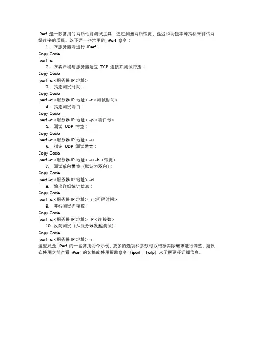
iPerf 是一款常用的网络性能测试工具,通过测量网络带宽、延迟和丢包率等指标来评估网络连接的质量。
以下是一些常用的iPerf 命令:1.在服务器端运行iPerf:Copy Codeiperf -s2.在客户端与服务器建立TCP 连接并测试带宽:Copy Codeiperf -c <服务器IP地址>3.指定测试时间:Copy Codeiperf -c <服务器IP地址> -t <测试时间>4.指定测试端口:Copy Codeiperf -c <服务器IP地址> -p <端口号>5.测试UDP 带宽:Copy Codeiperf -c <服务器IP地址> -u6.指定UDP 测试带宽:Copy Codeiperf -c <服务器IP地址> -u -b <带宽>7.测试单向带宽(默认为双向):Copy Codeiperf -c <服务器IP地址> -d8.输出详细统计信息:Copy Codeiperf -c <服务器IP地址> -i <间隔时间>9.并行测试连接数:Copy Codeiperf -c <服务器IP地址> -P <连接数>10.反向测试(从服务器发起测试):Copy Codeiperf -c <服务器IP地址> -r这些只是iPerf 的一些常用命令示例,更多的选项和参数可以根据实际需求进行调整。
建议在使用之前查看iPerf 的文档或使用帮助命令(iperf --help)来了解更多详细信息。
h248协议H.248协议,又称MEGACO(Multi-Edia Gateway Control),是基于H.323协议的一种新型协议,用于在IP网络上进行语音、视频和数据传输的媒体网关的控制。
它是一种应用层协议,旨在协调和控制媒体网关设备的多种功能。
H.248协议定义了控制网关如何分配、传递和处理语音、视频和数据传输的任务。
它允许媒体网关通过与控制点(Control Points)通信来传递传输和处理要求,这样就可以集中控制一个或多个网关设备。
H.248协议的架构包括以下几个核心组件:1. Control Point(CP):控制点是一个控制设备,负责发出控制指令和传递信令。
控制点可以是一个软件应用程序、一个媒体网关或一个媒体控制器。
控制点和网关之间通过IP网络进行通信。
2. Media Gateway Controller(MGC):媒体网关控制器是一个实体,负责协调和控制一个或多个媒体网关的资源。
它与控制点进行通信,接收和发送控制指令,并将其传递给相应的网关。
3. Media Gateway(MG):媒体网关是一个设备,用于将语音、视频和数据从一个网络传输到另一个网络。
它可以将传输格式进行转换、处理信令、采样和编解码等任务。
H.248协议的基本机制是通过传递消息来控制媒体网关。
控制点向媒体网关发送控制命令,媒体网关根据命令执行相应的操作,并向控制点返回结果。
控制命令包括创建和删除媒体会话、改变媒体流的参数、指定媒体传输路径等。
H.248协议还定义了通信过程中使用的消息格式,包括请求消息、响应消息和命令消息。
请求消息由控制点发送给网关,用于发出控制指令。
响应消息由网关发送给控制点,用于返回操作结果。
命令消息是在两个相邻的媒体网关之间传输的,用于协商传输和处理要求。
H.248协议的优势在于它的灵活性和可扩展性。
它可以通过定义新的命令和消息类型来支持不同的功能和需求,因此可以适应不同的应用场景。
RFC2889地址缓存容量测试案例一、RFC2889地址缓存容量解析1.1协议原理RFC2889为LAN交换设备的基准测试提供了方法学,它将RFC2544中为网络互联设备基准测试所定义的方法学扩展到了交换设备,提供了交换机转发性能(Forwarding Performance)、拥塞控制(Congestion Control)、延迟(Latency)、地址处理(Address Handling)和错误过滤(Error Filtering)等基准测试的方法说明。
1.2工作原理确定局域网交换设备的地址缓存容量。
以指定速率从客户端网口向DUT网口,发送源MAC地址不同而目的MAC地址相同的帧,然后测试帧被DU转发至服务端网口,监听端口监听泛洪帧或者转发错误帧,通过二分法的应可确定DUT 在无泛洪和无错误转发情况下,正确学习并转发的最大地址数。
1.3协议用途MAC地址学习是针对交换机来说的,交换机在收到一个报文时,会将报文的源mac地址记录在mac地址表选项中。
二、RFC2889地址缓存容量测试仪中可应用的场景2.1直连模式测试仪同时模拟客户端和服务器,测试流量穿过受测设备(交换机),得到受测设备的性能。
三、RFC2889地址缓存容量用例功能介绍3.1分配cpu核用例的运行需要分配cpu核数,RFC2889MAC地址学习速率的最高性能需要分配一定的核数。
3.2抓包设置可以设置需要抓的协议类型,指定IP地址、端口、文件大小或者包数。
可在运行前或运行中设置抓包。
四、RFC2889地址缓存容量测试案例4.1RFC2889MAC地址缓存容量用例拓扑图说明:测试仪使用“直连模式”模拟RFC2889MAC地址缓存容量的客户端和服务端,过一台交换机(直连模式),测试交换机性能。
4.2RFC2889MAC地址缓存容量用例目的本次案例测试华为交换机的地址缓存容量性能,测试仪模拟10000条MAC 地址,在交换机上查看MAC地址条数。


H248传输层承载的协议引言H248传输层承载的协议(H.248/M eg ac o)是一种用于控制媒体网关的通信协议。
它定义了在媒体网关和控制器之间进行通信所使用的消息格式和过程,为实现语音、视频和数据的传输提供了支持。
本文将介绍H248传输层承载的协议的定义、特点、工作原理以及应用场景。
定义H248传输层承载的协议(H.248/M eg ac o)是国际电信联盟(IT U)制定的一项标准,用于控制媒体网关中的I P电话和传统电话系统之间的转换。
它通过定义消息格式和过程,提供了控制信令和媒体交互的能力。
特点H.248具有以下特点:协议灵活性1.:H.248协议对网关和控制器之间的通信进行了灵活的定义,使得不同厂商的设备可以通过此协议进行交互。
它采用基于文本的消息格式,使得协议扩展更加容易。
分布式架构2.:H.248协议使用分布式架构,将媒体控制器与媒体网关分开,实现了对媒体资源的统一管理和控制。
这种架构使得系统更加可靠和可扩展。
支持多种媒体类型3.:H.248协议可以同时控制语音、视频和数据等多种媒体类型的传输。
它定义了各种媒体的编解码方式、传输格式和参数设置等。
提供丰富的功能4.:H.248协议支持通话的建立、修改和终止操作,可以实现呼叫转接、媒体增强功能、音频/视频编码选择等丰富的功能。
工作原理H.248协议的工作原理如下:媒体网关注册1.:媒体网关通过与控制器建立T CP/I P连接并发送注册请求,完成媒体网关的注册过程。
资源描述2.:媒体网关向控制器发送资源描述消息,描述其支持的媒体类型、编码方式和传输参数等。
会话建立3.:控制器向媒体网关发送会话建立请求,包括呼叫号码、媒体类型和媒体描述等信息。
媒体协商4.:控制器与媒体网关进行媒体协商,协商媒体的编解码方式、传输格式和网络参数等。
媒体传输5.:媒体网关通过将媒体数据转发到合适的传输链路上,完成媒体的传输。
会话终止6.:控制器向媒体网关发送会话终止消息,终止当前会话并释放相关资源。

rfc中常用的测试协议引言在计算机网络领域中,为了确保网络协议的正确性和稳定性,测试协议起到了至关重要的作用。
RFC(Request for Comments)是一系列文件,用于描述互联网相关协议、过程和技术。
在RFC中,也包含了一些常用的测试协议,用于验证和评估网络协议的功能和性能。
本文将介绍RFC中常用的测试协议,并深入探讨其原理和应用。
二级标题1:PING协议三级标题1.1:概述PING协议是一种常用的网络测试协议,用于测试主机之间的连通性。
它基于ICMP (Internet Control Message Protocol)协议,通过发送ICMP Echo Request报文并等待目标主机的ICMP Echo Reply报文来判断目标主机是否可达。
三级标题1.2:工作原理PING协议的工作原理如下: 1. 发送方主机生成一个ICMP Echo Request报文,并将目标主机的IP地址作为目的地。
2. 发送方主机将报文发送到网络中。
3.中间路由器收到报文后,将报文转发到下一跳路由器。
4. 目标主机收到ICMP Echo Request报文后,生成一个ICMP Echo Reply报文,并将其发送回发送方主机。
5. 发送方主机收到ICMP Echo Reply报文后,通过比较报文中的标识符和序列号等字段,判断目标主机是否可达。
三级标题1.3:应用场景PING协议在网络中的应用非常广泛,常用于以下场景: - 测试主机之间的连通性,判断网络是否正常工作。
- 测试网络延迟,通过计算ICMP Echo Request报文的往返时间来评估网络质量。
- 排查网络故障,通过检查ICMP Echo Reply报文中的错误码来定位故障原因。
二级标题2:Traceroute协议三级标题2.1:概述Traceroute协议用于跟踪数据包从源主机到目标主机经过的路径。
它通过发送一系列的UDP报文,并在每个报文中设置不同的TTL(Time to Live)值来实现。
RFC2544 概述IP网络设备是IP网络的核心,其性能的好坏直接影响IP网网络规模、网络稳定性以及网络可扩展性。
由于IETF没有对特定设备性能测试作专门规定,一般来说只能按照RFC2544(Benchmarking Methodology for Network Interconnect Devices)作测试。
以太网交换机测试标准则参照RFC2889(Benchmarking Methodology for LAN Sw itching Devices)。
但是由于网络互联设备除了通用性能测试以外通常还有一些特定的性能指标。
例如路由器区别于一般简单的网络互连设备,在性能测试时还应该加上路由器特有的性能测试。
例如路有表容量、路由协议收敛时间等指标。
网络互联设备例如路由器性能测试应当包括下列指标:吞吐量(Throughput):测试路由器包转发的能力。
通常指路由器在不丢包条件下每秒转发包的极限。
一般可以采用二分发查找该极限点。
时延(Latency):测试路由器在吞吐量范围内从收到包到转发出该包的时间间隔。
时延测试应当重复20次然后去其平均值。
丢包率(Packet loss rate):测试路由器在不同负荷下丢弃包占收到包的比例。
不同负荷通常指从吞吐量测试到线速(线路上传输包的最高速率),步长一般使用线速的10%。
背靠背帧数(Back-to-back frame):测试路由器在接收到以最小包间隔传输时不丢包条件下所能处理的最大包数。
该测试实际考验路由器缓存能力。
如果路由器具备线速能力(吞吐量=接口媒体线速),则该测试没有意义。
系统恢复时间(System recovery):测试路由器在过载后恢复正常工作的时间。
测试方法可以采用向路由器端口发送吞吐量110%和线速间的较小值持续60秒后将速率下降到50%的时刻到最后一个丢包的时间间隔。
如果路由器具备线速能力,则该测试没有意义。
系统复位(Reset):测试路由器从软件复位或关电重启到正常工作的时间间隔。
核心交换机双机热备解决方案一、项目背景稳定持续的系网络系统运行变得越来越重要,而原来有单机核心三层交换数据潜伏巨大的崩溃风险。
VRRP(虚拟路由冗余协议)技术来解决该问题,以实现主、备核心三层交换设备之间动态、无停顿的热切换。
二、方案设计:2.1、简要介绍VRRP的基本概念。
通常情况下,内部网络中的所有主机都设置一条相同的缺省路由,指向出口网关(即图1中的交换机S9300A),实现主机与外部网络的通信。
当出口网关发生故障时,主机与外部网络的通信就会中断。
图1 局域网缺省网关配置多个出口网关是提高系统可靠性的常见方法,但需要解决如何在多个出口网关之间进行选路的问题。
VRRP(Virtual Router Redundancy Protocol)是RFC3768定义的一种容错协议,通过物理设备和逻辑设备的分离,实现在多个出口网关之间选路,很好地解决了上述问题。
在具有多播或广播能力的局域网(如以太网)中,VRRP提供逻辑网关确保高利用度的传输链路,不仅能够解决因某网关设备故障带来的业务中断,而且无需修改路由协议的配置。
2.2、VRRP工作原理:vrrp只定义了一种报文——vrrp报文,这是一种组播报文,由主三层交换机定时发出来通告他的存在。
使用这些报文可以检测虚拟三层交换机各种参数,还可以用于主三层交换机的选举。
VRRP中定义了三种状态模型,初始状态Initialize,活动状态Master 和备份状态Backup,其中只有活动状态的交换机可以为到虚拟IP地址的的转发请求提供服务。
VRR报文是封装在IP报文上的,支持各种上层协议,同时VRRP还支持将真实接口IP地址设置为虚拟IP地址。
那么如何从备份组的多台交换机中选举Master?这项工作由我们在备份组内每台交换机上配置的相同IP地址的虚拟交换机完成。
虚拟交换机根据配置的优先级的大小选择主交换机,优先级最大的作为主交换机,状态为Master,若优先级相同(如果交换机没有配置优先级,就采用默认值100),则比较接口的主IP地址,主IP地址大的就成为主交换机,由它提供实际的路由服务。
UDP拥塞控制算法1. 引言UDP(User Datagram Protocol)是一种无连接的传输协议,它不提供可靠性和流量控制机制。
相比之下,TCP协议提供了可靠的数据传输和拥塞控制。
然而,在某些应用场景下,如实时音视频传输和游戏中,UDP协议的低延迟特性更加重要。
为了解决UDP网络中的拥塞问题,研究人员提出了一些基于UDP的拥塞控制算法。
2. UDP拥塞控制算法概述UDP拥塞控制算法旨在通过动态调整发送速率来避免网络拥塞,并尽可能地减少丢包率和延迟。
与TCP不同,UDP没有像滑动窗口、慢启动等机制来进行流量控制和拥塞控制。
因此,研究者们开发了一些基于UDP的拥塞控制算法。
3. UDP拥塞控制算法分类根据不同的设计思路和机制,UDP拥塞控制算法可以分为以下几类:3.1 基于丢包率的算法这类算法通过监测丢包率来判断网络是否发生拥塞,然后根据丢包率动态调整发送速率。
常见的算法有Packet Pair、Random Early Detection(RED)和Explicit Congestion Notification(ECN)等。
3.2 基于时延的算法这类算法通过测量网络时延来判断拥塞情况,并据此调整发送速率。
其中,最著名的算法是Network-Friendly Rate Control(NFRC)和Rate Adaptive Protocol (RAP)。
3.3 基于带宽估计的算法这类算法通过估计网络带宽来进行拥塞控制。
主要有Rate Control Protocol (RCP)、Rate-Based UDP和Scalable TCP-Friendly Rate Control(STFR)等。
4. 典型UDP拥塞控制算法介绍4.1 Packet PairPacket Pair是一种基于丢包率的UDP拥塞控制算法。
它通过发送两个连续数据包,并测量两个数据包之间的时延来判断网络是否发生拥塞。
如果时延较大,则说明网络可能发生了拥塞,此时发送速率会相应下降。
rfc中常用的测试协议摘要:1.RFC 简介2.RFC 中常用的测试协议a.网络协议测试1.网络数据包抓取和分析2.网络仿真和测试工具b.应用层协议测试1.HTTP 和HTTPS 测试2.FTP 和FTPS 测试3.SMTP 和SMTPS 测试c.安全协议测试1.TLS 和SSL 测试2.IPsec 测试d.传输协议测试1.TCP 和UDP 测试e.无线网络协议测试1.802.11 无线网络测试正文:RFC(Request for Comments)是一个用于讨论和记录互联网协议的标准文档系列。
在RFC 中,有许多常用的测试协议,这些协议用于确保互联网协议在实际应用中能够正常工作。
本文将详细介绍这些测试协议。
首先,RFC 中包含了大量的网络协议测试。
网络数据包抓取和分析是网络协议测试的基础,这对于诊断网络问题和优化网络性能至关重要。
此外,网络仿真和测试工具也是必不可少的,例如,网络模拟器(如NS-3)和测试平台(如Ixia)可以帮助工程师在实验室环境中模拟实际网络状况,从而对协议进行更严格的测试。
其次,应用层协议测试在RFC 中也占据重要地位。
HTTP 和HTTPS 是Web 应用中最常用的协议,有许多测试工具可以对它们的性能和安全性进行测试,例如,JMeter 和Locust 等负载测试工具。
此外,FTP 和FTPS、SMTP 和SMTPS 等传输协议也是常用的测试对象。
在安全协议方面,RFC 中包含了TLS 和SSL、IPsec 等协议的测试方法。
这些协议对于保护互联网数据传输的安全至关重要,因此需要进行严格的测试以确保其性能和安全性。
传输协议方面,TCP 和UDP 是互联网中最常用的传输协议,它们的测试方法也是RFC 中的重要内容。
TCP 测试关注可靠性和流量控制等方面,而UDP 测试则更注重数据传输速率和丢包率等指标。
最后,无线网络协议测试在RFC 中也有一定的比重。
例如,802.11 无线网络测试是评估无线局域网性能的关键。
附件4:企业秘密中国电信IP城域网设备测试规范(汇聚交换机)(V2.0)中国电信集团公司二零零六年一月目录1. 概述 (1)1.1范围 (1)1.2引用标准 (1)1.3缩略语 (2)2. 测试环境和仪表 (3)2.1测试环境 (3)2.2测试仪表 (3)3. 测试内容 (4)4. 二层交换功能测试 (4)4.1基本功能测试 (4)4.1.1 超长帧转发能力 (4)4.1.2 异常帧检测功能测试 (5)4.1.3 广播抑制功能测试 (6)4.2镜像功能 (6)4.2.1 端口镜像功能测试 (6)4.2.2 流镜像功能测试 (7)4.3生成树协议测试 (8)4.3.1 标准生成树测试 (8)4.3.2 快速生成树测试 (9)4.3.3 多生成树测试 (10)4.4VLAN堆叠功能测试 (11)4.4.1 基本功能 (11)4.4.2 扩展功能 (12)4.5端口聚合 (14)4.5.1 聚合链路数量测试 (14)4.5.2 聚合效率测试 (15)4.5.3 聚合链路收敛时间测试 (16)4.6二层组播功能测试 (17)4.6.1 UNTAGGED端口IGMP SNOOPING功能测试 (17)4.6.2 TAGGED端口IGMP SNOOPING功能测试 (18)4.6.3 组播组加入/离开时间测试 (19)4.7P RIV ATE V LAN功能测试 (20)4.8V LAN交换功能测试 (21)5. 访问控制和QOS功能 (22)5.1访问控制表方向性测试 (22)5.2二层访问控制表测试 (23)5.2.1 MAC地址访问控制表测试 (23)5.2.2 VLAN访问控制表测试 (23)5.2.4 SVLAN访问控制表测试 (25)5.3三层访问控制表功能测试 (26)5.3.1 IP地址访问控制表功能测试 (26)5.3.2 四层端口访问控制表功能测试 (26)5.4访问控制表数量及性能测试 (27)5.5业务分级 (28)5.5.1 基于VLAN ID的业务分级 (28)5.5.2 基于四层端口的业务分级 (29)5.5.3 SVLAN内外层标签802.1P优先级映射 (30)5.6优先级队列 (31)5.6.1 严格优先级队列 (31)5.6.2 轮询队列 (31)5.7速率限制 (32)5.7.1 入方向速率限制功能测试 (32)5.7.2 出方向速率限制功能测试 (33)5.7.3 速率限制颗粒度及精确性测试 (34)6. 转发性能测试 (35)6.1MAC地址学习速度 (35)6.2MAC地址表容量 (35)6.3最大VLAN数量测试 (36)6.4单端口吞吐量和时延测试 (37)6.5板内交换性能测试 (38)6.6板间交换性能测试 (39)6.7综合转发性能测试 (40)7. 可靠性和安全性 (41)7.1设备可靠性 (41)7.1.1 主控板和交换矩阵冗余 (41)7.1.2 电源冗余 (42)7.1.3 业务卡热插拔 (42)7.1.4 设备重启动时间 (43)7.2网络安全 (44)7.2.1 端口地址数量限制 (44)7.2.2 设备防ARP攻击测试 (45)7.2.3 设备防ICMP攻击测试 (45)7.2.4 设备防BPDU攻击测试 (46)8. 运行维护和网络管理 (47)8.1运行维护功能测试 (47)8.1.1 远程认证管理 (47)8.1.2 SSH登录测试 (48)8.1.3 日志记录 (48)8.1.4 DHCP Option82功能测试 (49)8.2.1 SNMPv1、SNMPv2支持测试 (50)8.2.2 SNMPv3支持测试 (50)8.2.3 SNMP访问地址限制 (51)8.2.4 MIB View安全访问控制功能测试 (52)8.2.5 SNMP Trap功能测试 (52)8.3管理信息库 (53)8.3.1 端口MIB的功能测试 (53)8.3.2 VLAN MIB的功能测试 (53)8.3.3 CPU利用率、内存占用率的功能测试 (54)8.3.4 资源管理信息功能测试 (54)8.3.5 ACL管理信息功能测试 (55)8.3.6 QOS的管理功能测试 (55)8.3.7 二层组播MIB (56)8.3.8 SVLAN MIB (56)中国电信IP城域网设备测试规范-汇聚交换机1. 概述1.1 范围本规范主要参考我国相关标准、RFC标准、国际电信联盟ITU-T相关建议以及《中国电信城域网优化改造指导意见》、《中国电信城域网设备技术规范》编制。
Network Working Group S. Floyd Request for Comments: 4828 ICIR Category: Experimental E. Kohler UCLA April 2007 TCP Friendly Rate Control (TFRC):The Small-Packet (SP) VariantStatus of This MemoThis memo defines an Experimental Protocol for the Internetcommunity. It does not specify an Internet standard of any kind.Discussion and suggestions for improvement are requested.Distribution of this memo is unlimited.Copyright NoticeCopyright (C) The IETF Trust (2007).AbstractThis document proposes a mechanism for further experimentation, butnot for widespread deployment at this time in the global Internet.TCP-Friendly Rate Control (TFRC) is a congestion control mechanismfor unicast flows operating in a best-effort Internet environment(RFC 3448). TFRC was intended for applications that use a fixedpacket size, and was designed to be reasonably fair when competingfor bandwidth with TCP connections using the same packet size. This document proposes TFRC-SP, a Small-Packet (SP) variant of TFRC, that is designed for applications that send small packets. The designgoal for TFRC-SP is to achieve the same bandwidth in bps (bits persecond) as a TCP flow using packets of up to 1500 bytes. TFRC-SPenforces a minimum interval of 10 ms between data packets to prevent a single flow from sending small packets arbitrarily frequently.Flows using TFRC-SP compete reasonably fairly with large-packet TCPand TFRC flows in environments where large-packet flows and small-packet flows experience similar packet drop rates. However, inenvironments where small-packet flows experience lower packet droprates than large-packet flows (e.g., with Drop-Tail queues in unitsof bytes), TFRC-SP can receive considerably more than its share ofthe bandwidth.Floyd & Kohler Experimental [Page 1]Table of Contents1. Introduction (3)2. Conventions (5)3. TFRC-SP Congestion Control (5)4. TFRC-SP Discussion (9)4.1. Response Functions and Throughput Equations (9)4.2. Accounting for Header Size (12)4.3. The TFRC-SP Min Interval (13)4.4. Counting Packet Losses (14)4.5. The Nominal Packet Size (15)4.5.1. Packet Size and Packet Drop Rates (15)4.5.2. Fragmentation and the Path MTU (17)4.5.3. The Nominal Segment Size and the Path MTU (17)4.6. The Loss Interval Length for Short Loss Intervals (18)5. A Comparison with RFC 3714 (19)6. TFRC-SP with Applications that Modify the Packet Size (19)7. Simulations (20)8. General Discussion (21)9. Security Considerations (22)10. Conclusions (23)11. Acknowledgements (24)Appendix A. Related Work on Small-Packet Variants of TFRC (25)Appendix B. Simulation Results (26)B.1. Simulations with Configured Packet Drop Rates (26)B.2. Simulations with Configured Byte Drop Rates (30)B.3. Packet Dropping Behavior at Routers with Drop-TailQueues (32)B.4. Packet Dropping Behavior at Routers with AQM (37)Appendix C. Exploring Possible Oscillations in the Loss EventRate (42)Appendix D. A Discussion of Packet Size and Packet Dropping (43)Normative References (44)Informative References (44)Floyd & Kohler Experimental [Page 2]1. IntroductionThis document specifies TFRC-SP, an experimental, Small-Packetvariant of TCP-friendly Rate Control (TFRC) [RFC3448].TFRC was designed to be reasonably fair when competing for bandwidth with TCP flows, but to avoid the abrupt changes in the sending ratecharacteristic of TCP’s congestion control mechanisms. TFRC isintended for applications such as streaming media applications where a relatively smooth sending rate is of importance. Conventional TFRC measures loss rates by estimating the loss event ratio as describedin [RFC3448], and uses this loss event rate to determine the sending rate in packets per round-trip time. This has consequences for therate that a TFRC flow can achieve when sharing a bottleneck withlarge-packet TCP flows. In particular, a low-bandwidth, small-packet TFRC flow sharing a bottleneck with high-bandwidth, large-packet TCP flows may be forced to slow down, even though the TFRC application’s nominal rate in bytes per second is less than the rate achieved bythe TCP flows. Intuitively, this would be "fair" only if the network limitation was in packets per second (such as a routing lookup),rather than bytes per second (such as link bandwidth). Conventional wisdom is that many of the network limitations in today’s Internetare in bytes per second, even though the network limitations of thefuture might move back towards limitations in packets per second.TFRC-SP is intended for flows that need to send frequent smallpackets, with less than 1500 bytes per packet, limited by a minimuminterval between packets of 10 ms. It will better supportapplications that do not want their sending rates in bytes per second to suffer from their use of small packets. This variant isrestricted to applications that send packets no more than once every 10 ms (the Min Interval or minimum interval). Given thisrestriction, TFRC-SP effectively calculates the TFRC fair rate as if the bottleneck restriction was in bytes per second. Applicationsusing TFRC-SP could have a fixed or naturally-varying packet size, or could vary their packet size in response to congestion. Applications that are not willing to be limited by a minimum interval of 10 msbetween packets, or that want to send packets larger than 1500 bytes, should not use TFRC-SP. However, for applications with a minimuminterval of at least 10 ms between packets and with data packets ofat most 1500 bytes, the performance of TFRC-SP should be at least as good as that from TFRC.RFC 3448, the protocol specification for TFRC, stated that TFRC-PS(for TFRC-PacketSize), a variant of TFRC for applications that have a fixed sending rate but vary their packet size in response tocongestion, would be specified in a later document. This documentinstead specifies TFRC-SP, a variant of TFRC designed forFloyd & Kohler Experimental [Page 3]applications that send small packets, where applications could either have a fixed or varying packet size or could adapt their packet size in response to congestion. However, as discussed in Section 6 ofthis document, there are many questions about how such an adaptiveapplication would use TFRC-SP that are beyond the scope of thisdocument, and that would need to be addressed in documents that aremore application-specific.TFRC-SP is motivated in part by the approach in RFC 3714, whichargues that it is acceptable for VoIP flows to assume that thenetwork limitation is in bytes per second (Bps) rather in packets per second (pps), and to have the same sending rate in bytes per secondas a TCP flow with 1500-byte packets and the same packet drop rate.RFC 3714 states the following:"While the ideal would be to have a transport protocol that isable to detect whether the bottleneck links along the path arelimited in Bps or in pps, and to respond appropriately when thelimitation is in pps, such an ideal is hard to achieve. We would not want to delay the deployment of congestion control fortelephony traffic until such an ideal could be accomplished. Inaddition, we note that the current TCP congestion controlmechanisms are themselves not very effective in an environmentwhere there is a limitation along the reverse path in pps. While the TCP mechanisms do provide an incentive to use large datapackets, TCP does not include any effective congestion controlmechanisms for the stream of small acknowledgement packets on the reverse path. Given the arguments above, it seems acceptable tous to assume a network limitation in Bps rather than in pps inconsidering the minimum sending rate of telephony traffic."Translating the discussion in [RFC3714] to the congestion controlmechanisms of TFRC, it seems acceptable to standardize a variant ofTFRC that allows low-bandwidth flows sending small packets to achieve a rough fairness with TCP flows in terms of the sending rate in Bps, rather than in terms of the sending rate in pps. This isaccomplished by TFRC-SP, a small modification to TFRC, as describedbelow.Maintaining incentives for large packets: Because the bottlenecks in the network in fact can include limitations in pps as well as in Bps, we pay special attention to the potential dangers of encouraging alarge deployment of best-effort traffic in the Internet consistingentirely of small packets. This is discussed in more detail inSection 4.3. In addition, as again discussed in Section 4.3, TFRC-SP includes the limitation of the Min Interval between packets of 10 ms. Floyd & Kohler Experimental [Page 4]Packet drop rates as a function of packet size: TFRC-SP essentiallyassumes that the small-packet TFRC-SP flow receives roughly the same packet drop rate as a large-packet TFRC or TCP flow. As we show,this assumption is not necessarily correct for all environments inthe Internet.Initializing the Loss History after the First Loss Event: Section6.3.1 of RFC 3448 specifies that the TFRC receiver initializes theloss history after the first loss event by calculating the lossinterval that would be required to produce the receive rate measured over the most recent round-trip time. In calculating this lossinterval, TFRC-SP uses the segment size of 1460 bytes, rather thanthe actual segment size used in the connection.Calculating the loss event rate for TFRC-SP: TFRC-SP requires amodification in TFRC’s calculation of the loss event rate, because a TFRC-SP connection can send many small packets when a standard TFRCor TCP connection would send a single large packet. It is notpossible for a standard TFRC or TCP connection to repeatedly sendmultiple packets per round-trip time in the face of a high packetdrop rate. As a result, TCP and standard TFRC only respond to asingle loss event per round-trip time, and are still able to detectand respond to increasingly heavy packet loss rates. However, in ahighly-congested environment, when a TCP connection might be sending, on average, one large packet per round-trip time, a correspondingTFRC-SP connection might be sending many small packets per round-trip time. As a result, in order to maintain fairness with TCP, and to be able to detect changes in the degree of congestion, TFRC-SP needs to be sensitive to the actual packet drop rate during periods of highcongestion. This is discussed in more detail in the section below. 2. ConventionsThe key words "MUST", "MUST NOT", "REQUIRED", "SHALL", "SHALL NOT","SHOULD", "SHOULD NOT", "RECOMMENDED", "MAY", and "OPTIONAL" in this document are to be interpreted as described in [RFC2119].3. TFRC-SP Congestion ControlTFRC uses the TCP throughput equation given in Section 3.1 of[RFC3448], which gives the allowed sending rate X in bytes per second as a function of the loss event rate, segment size, and round-triptime. [RFC3448] specifies that the segment size s used in thethroughput equation should be the segment size used by theapplication, or the estimated mean segment size if there arevariations in the segment size depending on the data. This givesrough fairness with TCP flows using the same segment size.Floyd & Kohler Experimental [Page 5]TFRC-SP changes this behavior in the following ways.o The nominal segment size: The nominal segment size s defaults to1460 bytes. Following [RFC3714], this provides a goal offairness, in terms of the sending rate in bytes per second, with a TCP flow with 1460 bytes of application data per packet but withthe same packet drop rate. If the endpoint knows the MTU (Maximum Transmission Unit) of the path and the derived MSS (MaximumSegment Size) is less than 1460 bytes, then the endpoint SHOULDset the nominal segment size s to MSS bytes. In addition, if the endpoint knows the MTU of the path and the resulting MSS is lessthan 536 bytes, then the endpoint MUST set the nominal segmentsize s to MSS bytes.However, this document does not require that TFRC-SP endpointsdetermine the path MTU. While most paths allow an MSS of 1460bytes, some paths have a slightly smaller MSS due to tunnels(e.g., IPv6 over IPv4). In some specific cases, IPv4 paths mayexperience a much smaller path MTU. Due to the complications ofestimating the path MTU, and to the fact that most paths supportan MSS of at least 536 bytes, TFRC-SP as a default uses a nominal segment size of 1460 bytes. The nominal segment size is discussed in more detail in Section 4.5.3.o Taking packet headers into account: The allowed transmit rate X in bytes per second is reduced by a factor that accounts for packetheader size. This gives the application some incentive, beyondthe Min Interval, not to use unnecessarily small packets. Inparticular, we introduce a new parameter H, which represents theexpected size in bytes of network and transport headers to be used on the TFRC connection’s packets. This is used to reduce theallowed transmit rate X as follows:X := X * s_true / (s_true + H),where s_true is the true average data segment size for theconnection in bytes, excluding the transport and network headers. Section 4.1 of RFC 3448 states that where the packet size variesnaturally with the data, an estimate of the mean segment size can be used for s_true. As suggested in Section 4.1 of [RFC3448bis], when an estimate of the mean segment size is used for s_true, the estimate SHOULD be calculated over at least the last four lossintervals. However, this document does not specify a specificalgorithm for estimating the mean segment size.The H parameter is set to the constant 40 bytes. Thus, if theTFRC-SP application used 40-byte data segments, the allowedtransmit rate X would be halved to account for the fact that half Floyd & Kohler Experimental [Page 6]of the sending rate would be used by the headers. Section 4.2justifies this definition. However, a connection using TFRC-SPMAY instead use a more precise estimate of H, based on the actual network and transport headers to be used on the connection’spackets. For example, a Datagram Congestion Control Protocol(DCCP) connection [RFC4340] over IPv4, where data packets use the DCCP-Data packet type, and there are no IP or DCCP options, could set H to 20 + 12 = 32 bytes. However, if the TFRC implementation knows that the IP layer is using IPv6 instead of IPv4, then theconnection using TFRC-SP MAY still use the default estimate of 40 bytes for H instead of the actual size of 60 bytes, for simplicity of implementation.o Measuring the loss event rate in times of high loss: During short loss intervals (those at most two round-trip times), the loss rate is computed by counting the actual number of packets lost ormarked, not by counting at most one loss event per loss interval. Without this change, TFRC-SP could send multiple packets perround-trip time even in the face of heavy congestion, for asteady-state behavior of multiple packets dropped each round-trip time.In standard TFRC, the TFRC receiver estimates the loss event rate by calculating the average loss interval in packets, and inverting to get the loss event rate. Thus, for a short loss interval with N packets and K losses, standard TFRC calculates the size of that loss interval as N packets, contributing to a loss event rate of1/N. However, for TFRC-SP, for small loss intervals of at mosttwo round-trip times, if the loss interval consists of N packetsincluding K losses, the size of the loss interval is calculated as N/K, contributing to a loss event rate of K/N instead of 1/N.Section 5.4 of RFC 3448 specifies that the calculation of theaverage loss interval includes the most recent loss interval only if this increases the calculated average loss interval, as in the pseudocode below. However, in TFRC-SP the calculated lossinterval size for a short loss interval varies as a function ofthe number of packet losses that have been detected, allowingeither increases or decreases in the calculated loss interval size for the current short loss interval as new packets are received.Therefore, TFRC-SP adds the restriction that the calculation ofthe average loss interval can include the most recent lossinterval only if more than two round-trip times have passed since the beginning of that loss interval.Floyd & Kohler Experimental [Page 7]Let the most recent loss intervals be I_0 to I_n, with I_0 beingthe interval including the most recent loss event, with thecorresponding weights w_i as defined in RFC 3448. In RFC 3448(Section 5.4), the average loss interval I_mean is calculated asfollows:I_tot0 = 0;I_tot1 = 0;W_tot = 0;for (i = 0 to n-1) {I_tot0 = I_tot0 + (I_i * w_i);W_tot = W_tot + w_i;}for (i = 1 to n) {I_tot1 = I_tot1 + (I_i * w_(i-1));}I_tot = max(I_tot0, I_tot1);I_mean = I_tot/W_tot;In TFRC-SP, the average loss interval I_mean is instead calculated as follows:I_tot0 = 0;I_tot1 = 0;W_tot = 0;for (i = 0 to n-1) {I_tot0 = I_tot0 + (I_i * w_i);W_tot = W_tot + w_i;}for (i = 1 to n) {I_tot1 = I_tot1 + (I_i * w_(i-1));}If the current loss interval I_0 is "short"then I_tot = I_tot1;else I_tot = max(I_tot0, I_tot1);I_mean = I_tot/W_tot;o A minimum interval between packets: TFRC-SP enforces a MinInterval between packets of 10 ms. A flow that wishes itstransport protocol to exceed this Min Interval MUST use theconventional TFRC equations, rather than TFRC-SP. The motivation for this is discussed below.Floyd & Kohler Experimental [Page 8]4. TFRC-SP Discussion4.1. Response Functions and Throughput EquationsTFRC uses the TCP throughput equation given in [RFC3448], with thesending rate X in bytes per second as follows:sX = ------------------------------------------------------- ,R*sqrt(2*p/3) + (4*R* (3*sqrt(3*p/8) * p * (1+32*p^2)))where:s is the packet size in bytes;R is the round-trip time in seconds;p is the loss event rate, between 0 and 1.0, of the number of loss events as a fraction of the number of packets transmitted.This equation uses a retransmission timeout (RTO) of 4*R, and assumes that the TCP connection sends an acknowledgement for every datapacket.This equation essentially gives the response function for TCP as well as for standard TFRC (modulo TCP’s range of sender algorithms forsetting the RTO). As shown in Table 1 of [RFC3714], for high packet drop rates, this throughput equation gives rough fairness with themost aggressive possible current TCP: a SACK TCP flow usingtimestamps and Explicit Congestion Notification (ECN). Because it is not recommended for routers to use ECN-marking in highly-congestedenvironments with high packet dropping/marking rates (Section 7 of[RFC3168]), we note that it would be useful to have a throughputequation with a somewhat more moderate sending rate for packet droprates of 40% and above.The effective response function of TFRC-SP can be derived from theTFRC response function by using a segment size s of 1460 bytes, andusing the loss event rate actually experienced by the TFRC-SP flow.In addition, for loss intervals of at most two round-trip times, the loss event rate for TFRC-SP is estimated by counting the actualnumber of lost or marked packets, rather than by counting lossevents. In addition, the sending rate for TFRC-SP is constrained to be at most 100 packets per second.Floyd & Kohler Experimental [Page 9]For an environment with a fixed packet drop rate p, regardless ofpacket size, the response functions of TCP, TFRC, and TFRC-SP areillustrated as follows, given in KBps (kilobytes per second), for aflow with a round-trip time of 100 ms:<-- TCP and Standard TFRC -->Packet 14-byte 536-byte 1460-byteDropRate Segments Segments Segments-------- -------- -------- --------0.00001 209.25 2232.00 5812.490.00003 120.79 1288.41 3355.240.00010 66.12 705.25 1836.580.00030 38.10 406.44 1058.450.00100 20.74 221.23 576.120.00300 11.76 125.49 326.790.01000 6.07 64.75 168.610.03000 2.99 31.90 83.070.10000 0.96 10.21 26.580.20000 0.29 3.09 8.060.30000 0.11 1.12 2.930.40000 0.05 0.48 1.260.50000 0.02 0.24 0.63Table 1: Response Function for TCP and TFRC.Sending Rate in KBps, as a Function of Packet Drop Rate.<---------- TFRC-SP -------->Packet 14-byte 536-byte 1460-byteDropRate Segments Segments Segments-------- -------- -------- --------0.00001 5.40 57.60 150.000.00003 5.40 57.60 150.000.00010 5.40 57.60 150.000.00030 5.40 57.60 150.000.00100 5.40 57.60 150.000.00300 5.40 57.60 150.000.01000 5.40 57.60 150.000.03000 5.40 57.60 83.070.10000 5.40 26.58 26.580.20000 5.40 8.06 8.060.30000 2.93 2.93 2.930.40000 1.26 1.26 1.260.50000 0.63 0.63 0.63Table 2: Response Function for TFRC-SP.Sending Rate in KBps, as a Function of Packet Drop Rate.Maximum Sending Rate of 100 Packets per Second.Floyd & Kohler Experimental [Page 10]The calculations for Tables 1 and 2 use the packet loss rate for anapproximation for the loss event rate p. Scripts and graphs for the tables are available from [VOIPSIMS]. As the well-known TCP response function in Table 1 shows, the sending rate for TCP and standard TFRC varies linearly with segment size. The TFRC-SP response functionshown in Table 2 reflects the maximum sending rate of a hundredpackets per second; when not limited by this maximum sending rate,the TFRC-SP flow receives the same sending rate in KBps as the TCPflow with 1460-byte segments, given the same packet drop rate.Simulations showing the TCP, standard TFRC, and TFRC-SP sending rates in response to a configured packet drop rate are given in Tables 7,8, and 9, and are consistent with the response functions shown here. <-- TCP and Standard TFRC -->Byte 14-byte 536-byte 1460-byteDropRate Segments Segments Segments-------- -------- -------- --------0.0000001 284.76 929.61 1498.950.0000003 164.39 536.17 863.160.0000010 90.01 292.64 468.490.0000030 51.92 167.28 263.680.0000100 28.34 88.56 132.750.0000300 16.21 46.67 61.700.0001000 8.60 19.20 16.250.0003000 4.56 4.95 1.700.0010000 1.90 0.37 0.150.0030000 0.52 0.05 0.060.0100000 0.04 0.02 0.060.0300000 0.00 0.02 0.06Table 3: Response Function for TCP and TFRC.Sending Rate in KBps, as a Function of Byte Drop Rate.Floyd & Kohler Experimental [Page 11]<---------- TFRC-SP -------->Byte 14-byte 536-byte 1460-byteDropRate Segments Segments Segments-------- -------- -------- --------0.0000001 5.40 57.60 150.000.0000003 5.40 57.60 150.000.0000010 5.40 57.60 150.000.0000030 5.40 57.60 150.000.0000100 5.40 57.60 132.750.0000300 5.40 57.60 61.700.0001000 5.40 50.00 16.250.0003000 5.40 12.89 1.700.0010000 5.40 0.95 0.150.0030000 5.40 0.12 0.060.0100000 1.10 0.06 0.060.0300000 0.13 0.06 0.06Table 4: Response Function for TFRC-SP.Sending Rate in KBps, as a Function of Byte Drop Rate.Maximum Sending Rate of 100 Packets per Second.For Tables 3 and 4, the packet drop rate is calculated as 1-(1-b)^N, for a byte drop rate of b, and a packet size of N bytes. Thesetables use the packet loss rate as an approximation for the lossevent rate p. The TCP response functions shown in Table 3 for fixed byte drop rates are rather different from the response functionsshown in Table 1 for fixed packet drop rates; with higher byte droprates, a TCP connection can have a higher sending rate using*smaller* packets. Table 4 also shows that with fixed byte droprates, the sending rate for TFRC-SP can be significantly higher than that for TCP or standard TFRC, regardless of the TCP segment size.This is because in this environment, with small packets, TFRC-SPreceives a small packet drop rate, but is allowed to send at thesending rate of a TCP or standard TFRC flow using larger packets but receiving the same packet drop rate.Simulations showing TCP, standard TFRC, and TFRC-SP sending rates in response to a configured byte drop rate are given in Appendix B.2.4.2. Accounting for Header Size[RFC3714] makes the optimistic assumption that the limitation of the network is in bandwidth in bytes per second (Bps), and not in CPUcycles or in packets per second (pps). However, some attention must be paid to the load in pps as well as to the load in Bps. Even aside from the Min Interval, TFRC-SP gives the application some incentiveto use fewer but larger packets, when larger packets would suffice, Floyd & Kohler Experimental [Page 12]by including the bandwidth used by the packet header in the allowedsending rate.As an example, a sender using 120-byte packets needs a TCP-friendlyrate of 128 Kbps to send 96 Kbps of application data. This isbecause the TCP-friendly rate is reduced by a factor ofs_true/(s_true + H) = 120/160, to account for the effect of packetheaders. If the sender suddenly switched to 40-byte data segments,the allowed sending rate would reduce to 64 Kbps of application data; and the use of one-byte data segments would reduce the allowedsending rate to 3.12 Kbps of application data. (In fact, the MinInterval would prevent senders from achieving these rates, sinceapplications using TFRC-SP cannot send more than 100 packets persecond.)Unless it has a more precise estimate of the header size, TFRC-SPassumes 40 bytes for the header size, although the header could belarger (due to IP options, IPv6, IP tunnels, and the like) or smaller (due to header compression) on the wire. Requiring the use of theexact header size in bytes would require significant additionalcomplexity, and would have little additional benefit. TFRC-SP’sdefault assumption of a 40-byte header is sufficient to get a roughestimate of the throughput, and to give the application someincentive not to use an excessive amount of small packets. Becausewe are only aiming at rough fairness, and at a rough incentive forapplications, the default use of a 40-byte header in the calculations of the header bandwidth is sufficient for both IPv4 and IPv6.4.3. The TFRC-SP Min IntervalThe header size calculation provides an incentive for applications to use fewer, but larger, packets. Another incentive is that when thepath limitation is in pps, the application using more small packetsis likely to cause higher packet drop rates, and to have to reduceits sending rate accordingly. That is, if the congestion is in terms of pps, then the flow sending more pps will increase the packet drop rate, and have to adjust its sending rate accordingly. However, the increased congestion caused by the use of small packets in anenvironment limited by pps is experienced not only by the flow using the small packets, but by all of the competing traffic on thatcongested link. These incentives are therefore insufficient toprovide sufficient protection for pps network limitations.TFRC-SP, then, includes a Min Interval of 10 ms. This providesadditional restrictions on the amount of small packets used.Floyd & Kohler Experimental [Page 13]。