ESP8266_IoT_SDK_Programming Guide_v0.9.1
- 格式:pdf
- 大小:1.16 MB
- 文档页数:64

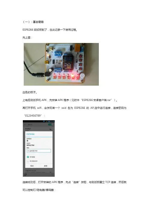
⼀,ESP8266下载和刷固件(基于Lua脚本语⾔)⽤⾃⼰的⼩板测试......安排上呢⼀, ESP8266下载和刷固件(Lua开发----体验⼀下lua开发的魅⼒所在)⼆, 控制⼀个灯亮灭三, TCP服务器四, TCP客户端五, UDP六, ⽂件操作(保存数据到8266内部)七, 外设操作(SPI,ADC)⼋, 再说......先看下载⾃⼰的固件填写好⾃⼰的的邮箱地址,然后选择好⾃⼰需要的功能,⼀会编译好的固件就会发到您的邮箱地址我下载的我⼀开始⽤的QQ邮箱,不过后来不知道怎么的我的qq邮箱不可以了,,,,所以就⽤的⾃⼰的新浪邮箱然后就会出现下⾯的界⾯,,等着哈对了还有Lua开发的API⽂档邮件发过来啦烧写固件的软件⽆论哪⼀个软件,模块的接线都⼀样现在烧写固件参考⽂章..对了亲们可能⽤的这种的GPIO0 默认是⼯作模式(不接线)。
如果接了低电平就是下载模式(给模块刷固件!!)所以接低电平。
CH_PD接⾼电平,其余除了TX,RX外可以不接线..其实在模块上电的时候如果GPIO0是低电平那么模块就⼯作在等待刷固件模式,,,在模块上电的时候如果GPIO0是⾼电平那么模块就⼯作在正常⼯作模式,由于没有按键什么的,所以可以先接好线再上电再看这⼀款后来补充-----关于选择内存⼤⼩问题,不同的型号内存⼤⼩不⼀样可以看也可以从我的百度云⾥⾯下按下key2然后断电上电,或者按key3复位⼀下,,,然后松开key2就可以了好了现在看⽤第⼆个软件刷固件选择固件给⼤家各种模块的Flash⼤⼩的表让模块处于更新固件模式,,就是Gpio0接低电平,,然后复位⼀下好了对了可能出现这呢是串⼝模块和WIFI模块通信不稳定导致的,,,⾃⼰⽤ch340就出现过这种情况,,,,但是⽤pl2303就没有出现过,,,,对于这种情况,我感觉第⼀有条件可以换⼀个串⼝模块,⽐如pl2303,或者CP2102等等...再者呢可以选择好的杜邦线,,尽量短......不过呢,,⽤pl2303下载好以后,,⽤ch340也可以了...............对了也可以尝试把这⾥改⼩⼀点感觉只要不通信那么多数据,,也能减少出错的机会说⼀下这个软件还有⼀个⽤途就是把bin⽂件合成⼀个bin⽂件现在可以打开串⼝调试助⼿看⼀下也可能显⽰正在格式化⽂件系统,,,那么就等⼀会等它格式完⽂件系统我们写lua⽤这个软件不要害怕新语⾔哈,,,使⽤使⽤就知道了....很好⽤,和c语⾔很接近,功能却很强哈,,其实咱们哈也⽤不到多少,,,,咱们是使⽤的8266的API。
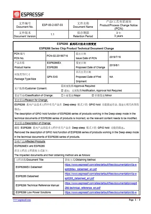
文件编号Document No.ESP-00-2-007-03文件名称Document Name产品/工艺变更通知Product/Process Change Notice(PCN)文件版本Document Version1.1保存期限Retention Period3年3 yearsESP8266 系列芯片技术文档变更ESP8266 Series Chip Product Technical Document ChangePCN编号PCN No.PCN-02-20190716提出日期Issue Date of PCN2019/7/16产品名称Product Name ESP8266EXESP8285变更日期Proposed Date of Change2019/8/1封装类型/尺寸Package Type/Size QFN 5X5首次出货日期Proposed Date of FirstShipmentNA客户批准/Customer Consent: 需要批准/Approval Required通知,无需批准/Notification, Approval Not Required变更等级/Classification of Change: 主要变更/Major 轻微变更/Minor变更原因/Reason for Change:ESP8266 系列产品技术文档中有关产品在Deep-sleep 模式下的GPIO hold 功能描述有误,故进行相关内容的修改。
The description of GPIO hold function of ESP8266 series of products working in the Deep-sleep mode in the technical documents of ESP8266 series of products is incorrect, so the relevant content needs to be modified.变更描述/Description of Change:删除ESP8266 系列产品的技术文档中有关产品在Deep-sleep 模式下的GPIO hold 功能的描述。
[ ] INTERNAL [ ] PUBLIC版本信息Wi-Fi联盟成员标志归Wi-Fi联盟所有。
文中提到的所有商标名称、商标和注册商标均属其各自所有者的财产,特此声明。
版权归© 2014 乐鑫信息技术有限公司所有。
保留所有权利。
目录版本信息 (2)目录 (3)1.前言 (4)2.虚拟机 (5)2.1.虚拟机软件 (5)2.2.虚拟电脑 (5)2.2.1.镜像 (5)2.2.2.导入 (5)2.2.3.网络 (8)2.2.4.共享文件夹 (8)2.2.5.界面 (10)3.开发工具 (11)3.1.编译器 (11)3.2.串口工具 (13)B转串口 (13)3.2.2.SecureCRT (14)3.3.下载工具 (14)3.3.1.XTCOM_UTIL (14)3.3.2.ESP_FLASH_DOWNLOAD (17)Assist (18)3.5.Postman (18)3.6.Tomcat (18)4.SDK软件包 (19)4.1.介绍 (19)4.2.目录结构 (19)4.3.编译及烧录方法 (20)4.3.1.不支持云端升级 (20)4.3.2.支持云端升级 (21)1.前言本文主要介绍基于ESP8266物联网模块的SDK相关使用方法,包括虚拟机安装设置、开发工具使用以及SDK软件包架构等。
2.虚拟机基于ESP8266物联网模块进行二次开发所需的相关开发工具已安装到虚拟机中,用户只需安装虚拟机软件,并导入虚拟电脑,即可进行开发。
2.1. 虚拟机软件虚拟机采用VirtualBox,下载地址为:https:///wiki/Downloads选择相应平台下载安装。
2.2. 虚拟电脑2.2.1. 镜像虚拟电脑镜像采用开放式虚拟化格式(*.ova),文件为ESP_IOT_SDK.ova,可以被其他虚拟机软件导入使用。
2.2.2. 导入VirtualBox默认情况,会将虚拟电脑导入系统盘,随着虚拟电脑的使用,会占用非常大的空间,建议设置虚拟电脑位置到非系统盘。
esp8266 教程ESP8266教程:连接WiFi网络步骤一:准备工作1.1 确保你已经具备以下物品:- ESP8266模块- 电脑- USB转串口模块- 杜邦线1.2 安装USB驱动程序在使用ESP8266之前,我们需要先安装USB转串口模块所需的驱动程序。
根据你所使用的转接模块型号,下载并安装相应的驱动程序。
步骤二:连接硬件2.1 将ESP8266与USB转串口模块连接起来。
使用杜邦线将ESP8266的VCC引脚连接到USB转串口模块的VCC引脚,将GND引脚连接到GND引脚,将TX引脚连接到RX引脚,将RX引脚连接到TX引脚。
2.2 将USB转串口模块连接到电脑的USB接口上。
步骤三:编写代码3.1 打开Arduino IDE,新建一个代码文件。
3.2 导入ESP8266库在Arduino IDE中,点击"工具"->"管理库",搜索并安装ESP8266库。
3.3 编写代码接下来,我们开始编写代码。
以下是一个简单的示例,用于连接WiFi网络。
```cpp#include <ESP8266WiFi.h>const char* ssid = "YourWiFiNetworkName";const char* password = "YourWiFiNetworkPassword";void setup() {Serial.begin(115200);WiFi.begin(ssid, password);while (WiFi.status() != WL_CONNECTED) {delay(1000);Serial.println("Connecting to WiFi...");}Serial.println("Connected to WiFi!");}void loop() {// 这里可以添加你的代码逻辑}```备注:将"YourWiFiNetworkName"替换成你的WiFi网络名称,将"YourWiFiNetworkPassword"替换成你的WiFi网络密码。
ESP8266用户手册ESP8266是一种广泛使用的无线模块,由Espressif Systems开发,被广泛使用于物联网和嵌入式设备的应用。
ESP8266的设计目标是为IoT应用提供连接便捷、底层可编程性和低成本的方案,它采用了Tensilica的L106 Diamond系列的32位大小端MCU。
由于其强大的功能和易于使用性,ESP8266已经成为了DIY电子爱好者的最爱。
本文将详细介绍ESP8266用户手册,以帮助新手更好地使用该模块。
1. 硬件介绍ESP8266是一款集成了Wi-Fi的芯片,它与主控芯片之间通过串行通信进行交互。
ESP8266的主体尺寸为16mm x 24mm,并且它的引脚和结构都是十分紧凑的。
ESP8266通常工作在3.3V的电压下,但是如果需要与5V的主控芯片进行通信,就需要进行电平转换。
2. 软件介绍在软件方面,ESP8266支持多种开发平台和语言。
目前,ESP8266最受欢迎的开发平台是Arduino IDE,用户可以通过该平台进行快速的开发工作。
此外,ESP8266也支持其他语言和开发平台,例如Python、Lua等。
3. WiFi模式ESP8266支持三种WiFi模式: STA模式、AP模式和STA+AP 模式。
STA模式是指将ESP8266作为一个WiFi的客户端连接到一个现有的WiFi网络,AP模式是指将ESP8266作为一个WiFi热点使其它设备可以连接到它,STA+AP模式是指将ESP8266同时作为WiFi客户端和WiFi热点。
4. AT指令ESP8266可以通过AT指令进行控制。
当我们要将ESP8266作为单片机处理时,我们可以使用AT指令来控制它的各种功能。
AT指令通常以“AT”开头,其后跟着具体的指令。
例如,AT+GMR是一个用来获取ESP8266固件版本信息的指令。
5. 固件升级在使用ESP8266过程中,我们可能需要升级不同版本的固件以获取新的功能和修复BUG。
安信可ESP8266模块使用指导ESP8266是一款低成本、低功耗的Wi-Fi模块,具有强大的处理能力和丰富的接口选项。
在这篇使用指导中,将向您介绍如何使用安信可ESP8266模块进行Wi-Fi通信。
1.硬件准备首先,您需要准备以下硬件设备:-安信可ESP8266模块-电脑或单片机开发板-USB转串口模块(用于连接ESP8266模块和电脑)2.硬件连接将ESP8266模块与USB转串口模块进行连接。
请确保连接正确,例如将ESP8266的VCC引脚连接到3.3V电源,GND引脚连接到地线,TX引脚连接到USB转串口的RX引脚,RX引脚连接到TX引脚。
3.软件准备在开始编程之前,您需要安装以下软件:- Arduino IDE(用于编写和上传代码)- ESP8266 Arduino核心库(用于支持ESP8266模块)安装完成后,打开Arduino IDE并选择适用于ESP8266的开发板。
4.编写代码以下是一个简单的示例代码,用于将ESP8266连接到Wi-Fi网络并发送HTTP请求:```Arduino#include <ESP8266WiFi.h>const char* ssid = "你的Wi-Fi名称";const char* password = "你的Wi-Fi密码";void setudelay(10);WiFi.begin(ssid, password);while (WiFi.status( != WL_CONNECTED)delay(500);Serial.print(".");}Serial.println("");Serial.println("Wi-Fi连接成功");Serial.println("发送HTTP请求...");WiFiClient client;client.println("GET /api/data HTTP/1.1");client.println("Connection: close");client.println(;}void loo//其他代码...```5.上传和运行代码将ESP8266模块连接到电脑,并在Arduino IDE中选择正确的串口和开发板。
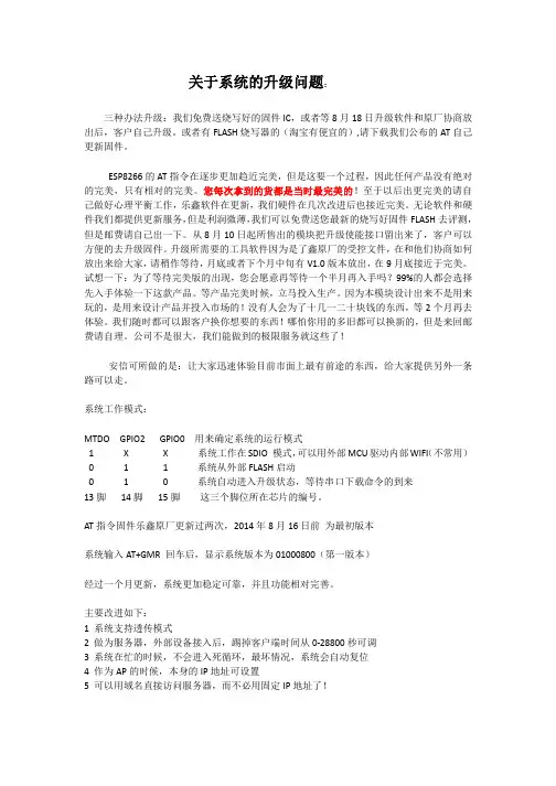
关于系统的升级问题:三种办法升级:我们免费送烧写好的固件IC,或者等8月18日升级软件和原厂协商放出后,客户自己升级。
或者有FLASH烧写器的(淘宝有便宜的),请下载我们公布的AT自己更新固件。
ESP8266的AT指令在逐步更加趋近完美,但是这要一个过程,因此任何产品没有绝对的完美,只有相对的完美。
您每次拿到的货都是当时最完美的!至于以后出更完美的请自己做好心理平衡工作,乐鑫软件在更新,我们硬件在几次改进后也接近完美。
无论软件和硬件我们都提供更新服务,但是利润微薄,我们可以免费送您最新的烧写好固件FLASH去评测,但是邮费请自己出一下。
从8月10日起所售出的模块把升级使能接口留出来了,客户可以方便的去升级固件。
升级所需要的工具软件因为是了鑫原厂的受控文件,在和他们协商如何放出来给大家,请稍作等待,月底或者下个月中旬有V1.0版本放出,在9月底接近于完美。
试想一下:为了等待完美版的出现,您会愿意再等待一个半月再入手吗?99%的人都会选择先入手体验一下这款产品。
等产品完美时候,立马投入生产。
因为本模块设计出来不是用来玩的,是用来设计产品并投入市场的!没有人会为了十几一二十块钱的东西,等2个月再去体验。
我们随时都可以跟客户换你想要的东西!哪怕你用的多旧都可以换新的,但是来回邮费请自理。
公司不是很大,我们能做到的极限服务就这些了!安信可所做的是:让大家迅速体验目前市面上最有前途的东西,给大家提供另外一条路可以走。
系统工作模式:MTDO GPIO2 GPIO0 用来确定系统的运行模式1 X X 系统工作在SDIO 模式,可以用外部MCU驱动内部WIFI(不常用)0 1 1 系统从外部FLASH启动0 1 0 系统自动进入升级状态,等待串口下载命令的到来13脚14脚15脚这三个脚位所在芯片的编号。
AT指令固件乐鑫原厂更新过两次,2014年8月16日前为最初版本系统输入AT+GMR 回车后,显示系统版本为01000800(第一版本)经过一个月更新,系统更加稳定可靠,并且功能相对完善。
第七讲ESP8266 RTOS SDK实现OTA在局域网内运行WebServer,将固件放到WebServer的目录下,使用网络助手触发ESP8266从WebServer上下载新固件,然后ESP8266重启,运行新固件。
笔名:火柴棍。
技术交流QQ群:476685983。
概述•ESP8266能通过网络远程更新固件,需要将编译生成的user1.bin和user2.bin放到服务器上,可以使用用户自己的服务器,也可以使用乐鑫官方提供的免费服务器。
•一.使用用户自己的服务器,这方式比较简单,将新的固件放到服务器的路径下,ESP8266使用http get的方式下载新的固件写到FLASH里面,然后重启运行新的固件。
•二.使用乐鑫官方提供的免费服务器,这种方式要复杂一些,毕竟使用别人的东西,需要遵循别人定的规则,首先要从乐鑫官网申请一个key(密匙),将这个密匙写到程序中,再将新的固件放到乐鑫的服务器上,然后填写一些和固件相关的信息,程序中也要有相关的部分。
程序可参照官方的:ESP8266 IOT PLATFORM,文档可参考:99C-ESP8266_FOTA_UPGRADE_CN.PDF。
我在开发时使用的是自己的服务器,所以我主要讲解使用开发着自己的服务器做远程固件升级。
首先需要弄清楚ESP8266的flash区域划分,为什么有user1.bin和user2.bin?ESP8266在FLASH中划分了两块空间存放固件,FLASH中的系统参数区设置了ESP8266启动时运行那块空间的固件,user1还是user2。
如果ESP8266当前运行的是user1.bin,那么固件更新时,就下载user2.bin,并且存储在user2.bin的FLASH空间,下载完成后,设置系统参数,启动时运行user2.bin;如果ESP8266当前运行的是user2.bin,那么固件更新时,就下载user1.bin,并且存储在user1.bin的FLASH空间,下载完成后,设置系统参数,启动时运行user1.bin。
ESP8266 Phy Init Bin Parameter Configuration GuideVersion 1.0Espressif SystemsCopyright © 2018About This Guide This guide provides the parameter configuration for ESP8266 phy init bin.Release NotesDate Version Release notes2018.12V1.0Initial releaseDocumentation Change NotificationEspressif provides email notifications to keep customers updated on changes totechnical documentation. Please subscribe at https:///en/subscribe.CertificationDownload certificates for Espressif products from https:///en/certificates.Table of Contents....................................................................................... 1.Structure of ESP8266 Phy Init Bin 1.................................................................................... 2.Check Bits for ESP8266 Phy Init Bin 2.......................................................................................... 3.Version of ESP8266 Phy Init Bin 3............................................................................................... 4.Selection of Crystal Oscillator 4.......................................................................................................... 5.Six Levels of TX Power 5.......................................................................................... 6.TX Power for Various Data Rates 6.................................................................................................................... 7.TX Power Limits 7..........................................................................................7.1.Value Range of the TX Power Limits 77.2.Parameters for the TX Power Limits 7................................................................................................................................................................................................................. 8.RF Calibration 91. Structure of ESP8266 Phy Init Bin 1.Structure of ESP8266 Phy InitBin ESP8266 phy init bin is comprised of a 128-byte phy init data as shown in Table 1-1:Table 1-1. Structure of ESP8266 Phy Init BinName Sizephy init data128 bytes2. Check Bits for ESP8266 Phy Init Bin 2.Check Bits for ESP8266 PhyInit Bin The check bits for ESP8266 phy init bin are stored in byte zero of phy init data, and therelevant parameter is Init_bin_magic with default value of 0x5. The check bits are used forverifying the data location in ESP8266 phy init bin. If the parameter value is the same asthe default value when reading data, it is assumed that data are stored correctly inESP8266 phy init bin.Table 2-1. Check Bits for ESP8266 Phy Init BinLocation in phy init data Parameter Name Default Value Description0Init_bin_magic5For check3. Version of ESP8266 Phy Init Bin3.Version of ESP8266 Phy InitBinThe version information of ESP8266 phy init bin is stored in byte 1 of phy init data.For example, ESP8266_esp_data_bin_v08.bin represents Version 08, which is stored inbyte 1 as 0x8.Table 3-1. Version of ESP8266 Phy Init BinLocation in phy init data Parameter Name Default Value Description1Init_bin_version8phy init bin version4. Selection of Crystal Oscillator 4.Selection of Crystal OscillatorThe parameter crystal_sel allows you to select a crystal oscillator. The available options aregiven in Table 4-1. Currently, ESP8266 mainly supports 26 MHz and 40 MHz crystaloscillators.Table 4-1. Selection of Crystal OscillatorLocation in phy init data Parameter Name Default Value Description48crystal_sel10: 40 MHz crystal oscillator 1: 26 MHz crystal oscillator 2: 24 MHz crystal oscillator5. Six Levels of TX Power 5.Six Levels of TX PowerTX power can be switched between six levels. The indexes for the six levels are thenumbers from 0 to 5 at the end of the parameter names. For example, the index fortxpwr_qdb_0 is 0, representing the maximum TX power. From txpwr_qdb_0 totxpwr_qdb_5, the TX power decreases progressively.Default TX power settings can be found in Table 5-1.Table 5-1. Six Levels of TX PowerLocation in phy init data Parameter Name Default Value Unit Actual TX Power34txpwr_qdb_0780.25 dB19.5 dBm35txpwr_qdb_1740.25 dB18.5 dBm36txpwr_qdb_2700.25 dB17.5 dBm37txpwr_qdb_3640.25 dB16 dBm38txpwr_qdb_4600.25 dB15 dBm39txpwr_qdb_5560.25 dB14 dBm6. TX Power for Various Data Rates 6.TX Power for Various DataRates You can choose from any of the six TX power levels for different data rates. The columnDefault value in Table 6-1 contains the TX power index.Table 6-1. TX Power for Various Date RatesLocation in phy init data Parameter Name Data rate/mode DefaultValueDescription40txpwr_index_0MCS0, 1 Mbit/s, 2 Mbit/s, 5.5 Mbit/s, 11 Mbit/s,6 Mbit/s, 9 Mbit/s0Select txpwr_qdb_041txpwr_index_1MCS1, 12 Mbit/s0Select txpwr_qdb_0 42txpwr_index_2MCS2, 18 Mbit/s1Select txpwr_qdb_1 43txpwr_index_3MCS3, 24 Mbit/s1Select txpwr_qdb_1 44txpwr_index_4MCS4, 36 Mbit/s2Select txpwr_qdb_2 45txpwr_index_5MCS5, 48 Mbit/s3Select txpwr_qdb_3 46txpwr_index_6MCS6, 54 Mbit/s4Select txpwr_qdb_4 47txpwr_index_7MCS75Select txpwr_qdb_596txpwr_index_11b_en802.11b00: use txpwr_index_0 toset TX Power for 802.11b1: use bytes 97 and 98 toset TX Power for 802.11b97txpwr_index_11b_01 Mbit/s,2 Mbit/s0Select txpwr_qdb_098txpwr_index_11b_15.5 Mbit/s, 11 Mbit/s0Select txpwr_qdb_07. TX Power Limits7.TX Power LimitsThe TX power limits have been set mainly to limit the maximum powers for channels 1, 11,13 and 14 in order to conform to the certification test results.7.1.Value Range of the TX Power LimitsThe TX power limits are set against the six levels. The value range of the limits is [0:5],which includes the values presented in Table 7-1.7.2.Parameters for the TX Power LimitsThe parameters for the TX power limits are specified in Table 7-2. For example, if the valueof byte 78 is set to 2, the bytes 30-33 are enabled to configure the maximum TX powers for channels 1, 11, 13 and 14.Table 7-1. Values of the TX Power Limits ValueTX Power Limit (Unit: 0.25 dB)0txpwr_qdb_01txpwr_qdb_12txpwr_qdb_23txpwr_qdb_34txpwr_qdb_45txpwr_qdb_5Table 7-2. Parameters for the TX Power Limits Location inphy init data Parameter name Default value Description78fcc_enable 00: disable bytes 30-331: reserved2: enable bytes 30-33 to set maximum TXpower30mpwr_chan10Set the maximum TX power for 802.11 b/g/n mode at channel 1, range [0:5]. 0xf8 isan invalid parameter.31mpwr_chan110Set the maximum TX power for 802.11 b/g/n mode at channel 11, range [0:5]. 0xf8is an invalid parameter.7. TX Power Limits32mpwr_chan130Set the maximum TX power for 802.11 b/ g/n mode at channel 13, range [0:5]. 0xf8 is an invalid parameter.33mpwr_chan140Set the maximum TX power for 802.11 b/ g/n mode at channel 14, range [0:5]. 0xf8 is an invalid parameter.8. RF Calibration 8.RF CalibrationThe values of the parameter RF_calibration are shown in Table 8-1. To ensure better RFperformance, it is recommend to set RF_calibration to 3, otherwise the RF performancemay become poor.Table 8-1. Parameter of RF CalibrationLocation inphy init dataParameter name Default value Description114RF_calibration30 & 1: only used for setting TX power 2: No RF calibration3: Conduct all RF calibrationDisclaimer and Copyright NoticeInformation in this document, including URL references, is subject to change without notice.THIS DOCUMENT IS PROVIDED AS IS WITH NO WARRANTIES WHATSOEVER,INCLUDING ANY WARRANTY OF MERCHANTABILITY , NON-INFRINGEMENT, FITNESS FOR ANY PARTICULAR PURPOSE, OR ANY WARRANTY OTHERWISE ARISING OUT OF ANY PROPOSAL, SPECIFICATION OR SAMPLE.All liability, including liability for infringement of any proprietary rights, relating to use of information in this document is disclaimed. No licenses express or implied, by estoppel or otherwise, to any intellectual property rights are granted herein.The Wi-Fi Alliance Member logo is a trademark of the Wi-Fi Alliance. The Bluetooth logo is a registered trademark of Bluetooth SIG.All trade names, trademarks and registered trademarks mentioned in this document are property of their respective owners, and are hereby acknowledged. Copyright © 2018 Espressif Inc. All rights reserved.Espressif IoT Team。
esp8266ESP8266是一款非常流行的Wi-Fi模块,广泛应用于物联网和智能家居领域。
本文将介绍ESP8266的基本特性、应用场景以及如何使用它进行开发。
第一部分:ESP8266简介ESP8266是由乐鑫科技(Espressif Systems)开发的一款低成本、低功耗Wi-Fi模块。
它采用了Tensilica Xtensa LX106核心处理器,主频80MHz,内置32位处理器和Wi-Fi功能,支持TCP/IP协议栈。
ESP8266模块内部集成了一些常见硬件接口,如UART、SPI和GPIO,方便开发者进行接口扩展和外部设备连接。
第二部分:ESP8266的特性1. 低成本和低功耗:ESP8266的成本非常低,适合大规模应用。
它的功耗也很低,可以满足电池供电的需求。
2. 强大的处理能力:虽然ESP8266主频只有80MHz,但其内置的32位处理器足够强大,能够处理复杂的计算任务。
3. Wi-Fi功能:ESP8266支持802.11 b/g/n标准,可以快速连接到无线网络,实现远程控制和数据传输。
4. 可编程性:ESP8266内置了存储器,可以用于存储程序代码和数据,方便开发者进行程序开发和扩展。
5. 开放源代码:ESP8266的SDK是开源的,开发者可以根据自己的需求进行定制和修改。
第三部分:ESP8266的应用场景1. 物联网应用:ESP8266可以连接到互联网,实现与云平台的数据交互,适用于智能家居、智能农业、智能城市等物联网应用。
2. 远程控制和监控:利用ESP8266的Wi-Fi功能,可以远程控制和监控设备,例如远程开关灯、监控温度。
3. 数据采集和传输:ESP8266可以连接到各种传感器,采集实时数据并传输到服务器或云平台,实现数据的实时监测和分析。
4. 物联网网关:ESP8266可以作为物联网网关使用,连接各种传感器和设备,实现设备间的通信和数据传输。
第四部分:ESP8266的开发和编程ESP8266的开发可以使用多种编程语言和工具,如Arduino IDE、MicroPython和Lua等。
ESP8266-DevKitSUser GuideVersion 1.0Espressif SystemsCopyright © 2020About This Guide This user guide provides information on ESP8266-DevKitS-development board.Release NotesDate Version Release notes2020.02V1.0Initial release.Documentation Change NotificationEspressif provides email notifications to keep customers updated on changes totechnical documentation. Please subscribe here.CertificationDownload certificates for Espressif products from here.Tables of Contents ................................................................................................................................ 1.Overview 1.......................................................................................................... 2.Functional Description 2............................................................................................................ 3.How to Flash a Board 4................................................................................................................3.1.Hardware Preparation 4.........................................................................................................................3.2.Hardware Setup 4..........................................................................................................................3.3.Software Setup 4................................................................................................................. 4.Board Dimensions 5.............................................................................................................. 5.Hardware Reference 6............................................................................................................................5.1.Block Diagram 65.2.Power Supply Options 6...........................................................................................................................................................................................................................................5.3.Header Blocks 6A.Appendix—Learning Resources 8.........................................................................................................................................................................................................A.1.Must-Read Documents 8................................................................................................................A.2.Must-Have Resources 91. Overview 1.OverviewESP8266-DevKitS is Espressif’s flashing board designed specifically for ESP8266. It can beused to flash an ESP8266 module without soldering the module to the power supply andsignal lines. With a module mounted, ESP8266-DevKitS can also be used as a minidevelopment board like ESP8266-DevKitC.ESP8266-DevKitS supports the following ESP8266 modules:-ESP-WROOM-02-ESP-WROOM-02D-ESP-WROOM-02U2. Functional Description 2.Functional DescriptionFigure 2-1. ESP8266-DevKitSThis chapter introduces key components, interfaces and controls of ESP8266-DevKitSdevelopment board:•Spring PinsConnect and fix the module. These spring pins fit castellated holes on the module.• 2.54 mm Female HeadersConnect to jumper wires and other development boards. For description of femaleheaders, please refer to 5.3 Header Blocks.•USB-to-UART BridgeA single chip USB-UART bridge provides up to 3 Mbps transfers rates.2. Functional Description •LDO5V-to-3.3V Low dropout voltage regulator (LDO).•Boot ButtonDownload button. Holding down the Boot button and pressing the EN button initiates the firmware download mode. Then users can download firmware through the serial port.•Micro USB Port/Micro USB ConnectorUSB interface. Power supply for the board and the communication interface betweena computer and the board.•EN ButtonReset button. Pressing this button resets the system.•Power On LEDTurns on when the USB or power supply is connected to the board.3. How to Flash a Board 3.How to Flash a Board 3.1.Hardware Preparation• 1 x ESP8266 module of your choice• 1 x USB 2.0 cable (Standard-A to Micro-B)• 1 x PC loaded with Windows, Linux or Mac OS3.2.Hardware SetupPlease mount a module of your choice onto your ESP8266-DevKitS according to thefollowing steps:•Gently put your module on the ESP8266-DevKitS board. Make sure that castellated holes on your module are aligned with spring pins on the board.•Press your module down into the board until it clicks.•Check whether all spring pins are inserted into castellated holes. If there are some misaligned spring pins, place them into castellated holes with tweezers.3.3.Software SetupFor step-by-step introductions, please refer to ESP8266 Quick Start Guide.Note:1.To flash binary files, the ESP32 chip should be set to UART boot mode. This can be done either by theflash tool automatically, or by holding down the Boot button and tapping the EN button.2.After binary files have been flashed, please reset or power up your ESP32 module again to run theflashed application (this step is executed automatically by the flash tool by default).4. Board Dimensions 4.Board DimensionsFigure 4-1. Board Dimensions5.Hardware Reference 5.1.Block DiagramFigure 5-1. ESP8266-DevKitS Block Diagram5.2.Power Supply OptionsThere are three mutually exclusive ways to provide power to the board:•Micro USB port, default power supply•5V and GND header pins•3V3 and GND header pinsIt is advised to use the first option: micro USB port.5.3.Header BlocksTable 5-1. Header BlockLocation Label SignalL1G GNDL23V3VDD 3V3L33V3VDD 3V3L4EN CHIP_ENL5G GNDL614GPIO14L712GPIO12L813GPIO13L915GPIO15L102GPIO2L110GPIO0L12G GNDL135V External 5VL14G GNDL15G GNDR1G GNDR216GPIO16R3G GNDR4TX U0TXDR5RX U0RXDR6G GNDR74GPIO4R8RST EXT_RSTBR95GPIO5R10ADC To TOUT after a voltage divider R11G GNDR12G GNDR13G GNDR14G GNDR15G GNDA.Appendix—LearningResources A.1.Must-Read Documents•ESP8266-DevKitS Reference DesignDescription: This zip package include ESP8266-DevKitS schematics, PCB layout,gerber and BOM files, and spring design files.•ESP8266 Quick Start GuideDescription: This document is a quick user guide to getting started with ESP8266. Itincludes an introduction to the ESP-LAUNCHER, how to download firmware on to theboard and run it, how to compile the AT application, structure and the debuggingmethod of RTOS SDK. Basic documentation and other related resources for theESP8266 are also provided.•ESP8266 SDK Getting Started GuideDescription: This document takes ESP-LAUNCHER and ESP-WROOM-02 as examplesto introduce how to use ESP8266 SDK. The contents include preparations beforecompilation, SDK compilation and firmware download.•ESP-WROOM-02 DatasheetDescription: ESP-WROOM-02 is a SMD module that integrates ESP8266EX. Themodule has been adjusted to get the best RF performance.•ESP-WROOM-02D/ESP-WROOM-02U DatasheetDescription: ESP-WROOM-02D and ESP-WROOM-02U are ESP8266EX-basedmodules developed by Espressif. Compared with ESP-WROOM-02, the RFperformance of ESP-WROOM-02D and ESP-WROOM-02U are optimized.•ESP-WROOM-02 Reference DesignDescription: This zip package includes ESP-WROOM-02 hardware downloadingresources, manufacturing specifications, BOM and schematics.•ESP-WROOM-02D/ESP-WROOM-02U Reference DesignDescription: This zip package includes ESP-WROOM-02D and ESP-WROOM-02Umodule reference design resources, including schematics, PCB layout, gerber files andBOM lists.•ESP-WROOM-02 PCB Design and Module Placement GuideDescription: The ESP-WROOM-02 module is designed to be soldered to a host PCB.This document compares six different placements of the antenna on a host board andprovides notes on designing PCB.•ESP8266 Hardware ResourcesDescription: This zip package includes manufacturing specifications of the ESP8266board and the modules, manufacturing BOM and schematics.•ESP8266 AT Command ExamplesDescription: This document introduces some specific examples of using Espressif ATcommands, including single connection as a TCP Client, UDP transmission andtransparent transmission, and multiple connection as a TCP server.•ESP8266 AT Instruction SetDescription: This document provides lists of AT commands based onESP8266_NONOS_SDK, including user-defined AT commands, basic AT commands,Wi-Fi AT commands and TCP/IP-related AT commands. It also introduces thedownloading of AT firmware into flash.•TCP/UDP UART Passthrough Test DemonstrationDescription: This guide is intended to help users run a TCP & UDP passthrough test onthe ESP8266 IoT platform.•FAQA.2.Must-Have Resources•ESP8266 SDKsDescription: This website page provides links to the latest version of ESP8266 SDK andthe older ones.•ESP8266 ToolsDescription: This website page provides links to the ESP8266 flash download tools andESP8266 performance evaluation tools.•ESP8266 App•ESP8266 Certification and Test Guide•ESP8266 BBS•ESP8266 ResourcesDisclaimer and Copyright NoticeInformation in this document, including URL references, is subject to change without notice.THIS DOCUMENT IS PROVIDED AS IS WITH NO WARRANTIES WHATSOEVER,INCLUDING ANY WARRANTY OF MERCHANTABILITY , NON-INFRINGEMENT, FITNESS FOR ANY PARTICULAR PURPOSE, OR ANY WARRANTY OTHERWISE ARISING OUT OF ANY PROPOSAL, SPECIFICATION OR SAMPLE.All liability, including liability for infringement of any proprietary rights, relating to use of information in this document is disclaimed. No licenses express or implied, by estoppel or otherwise, to any intellectual property rights are granted herein.The Wi-Fi Alliance Member logo is a trademark of the Wi-Fi Alliance. The Bluetooth logo is a registered trademark of Bluetooth SIG.All trade names, trademarks and registered trademarks mentioned in this document are property of their respective owners, and are hereby acknowledged. Copyright © 2020 Espressif Inc. All rights reserved.Espressif IoT Team。
ESP8266_用户手册_V03关键信息项:1、产品名称:ESP82662、版本号:V033、功能描述4、使用方法5、技术规格6、注意事项11 产品介绍ESP8266 是一款高性能、低功耗的 WiFi 模块,为用户提供便捷的无线连接解决方案。
111 主要特点集成 WiFi 功能低功耗设计小巧轻便易于集成到各种设备中112 应用场景智能家居工业控制智能穿戴设备12 功能描述121 WiFi 连接功能支持 24GHz 频段能够连接到各种 WiFi 网络实现稳定的数据传输122 数据处理能力具备一定的数据处理能力,可对接收和发送的数据进行处理123 接口功能提供多种接口,方便与其他设备进行通信13 使用方法131 硬件连接介绍与其他硬件设备的连接方式和注意事项132 软件配置详细说明如何进行软件设置和参数配置133 编程开发提供相关的编程接口和示例代码14 技术规格141 工作电压范围142 工作温度范围143 传输速率144 接收灵敏度15 注意事项151 电源稳定性确保供电电源的稳定性,以避免模块工作异常152 电磁干扰避免在强电磁干扰环境中使用,以免影响 WiFi 信号153 散热问题在长时间工作时,注意模块的散热情况154 软件更新及时关注官方发布的软件更新,以获取更好的性能和功能155 法律法规在使用过程中,遵守相关的法律法规,不得用于非法用途16 故障排除161 连接问题分析 WiFi 连接失败的可能原因和解决方法162 数据传输异常处理数据传输中断或错误的情况17 售后服务提供售后服务的联系方式和服务内容,保障用户在使用过程中的权益。
18 版权声明声明对本用户手册及相关技术的版权归属和使用限制。
以上协议内容仅供参考,您可以根据实际需求进行修改和完善。
arduino开发ESP8266学习笔记九---------ESP8266⽹络服务器(通过。
⽹络服务器有很多种类型,它们的功能也⼗分丰富。
通常承担⽹络服务器⼯作的设备都是运算能⼒⽐较强⼤的电脑。
我们的ESP866-NodeMCU虽然也能实现⽹络服务器的⼀些功能,但是毕竟它的运算能⼒是⽆法与那些昂贵的服务器电脑相媲美的,因此ESP8266-NodeMCU只能实现⼀些基本的⽹络服务功能。
不过这些基本的⽹络服务功能已经⾜够我们开发物联⽹项⽬了。
在接下来的⼏节教程⾥,我们将⼀起来学习如何让ESP8266-NodeMCU来实现⽹络服务功能。
⽹络服务是⼀个很宽泛的概念,我们在这⾥即将给您介绍的是⽹络服务中的⽹页服务功能。
所谓⽹页服务就是专门⽤于⽹页浏览的服务。
⼀、使⽤浏览器访问ESP8266服务器 代码:#include <ESP8266WiFi.h>#include <ESP8266WiFiMulti.h>#include <ESP8266WebServer.h>ESP8266WiFiMulti WiFiMulti;//建⽴ESP8266WiFiMulti对象,对象名称为WiFiMultiESP8266WebServer esp8266_server(80);//建⽴ESP8266WebServer对象,对象名称是“esp8266_server”//括号中的数字是⽹络服务器响应http请求的端⼝号//⽹络服务器http端⼝号为80,因此这⾥使⽤80为端⼝号int led=14;//设置指⽰灯void setup(){pinMode(led,OUTPUT);Serial.begin(9600);WiFiMulti.addAP("vivo","QiFei159874");//这条指令就是告诉ESP8266下⾯会告诉你多个WiFi⽹络名称和密码WiFiMulti.addAP("vivo1","qifei159874");//注意这⾥的双引号要加上,没加报错WiFiMulti.addAP("vivo2","QIFEI159874");//digitalWrite(led,HIGH);//默认LED是熄灭的//运⾏⾃定义函数,当未连接到路由器的过程中,闪烁LED,直到连接成功,点亮LED//gotowifi();Serial.println("WiFi正在连接中");int i=0;while(WiFiMulti.run()!=WL_CONNECTED)//WiFiMulti.run()和WiFi.Status()功能⼀样,都是⽤来表⽰当前WiFi连接的状态{delay(1000);Serial.print(".");}Serial.println('\n');Serial.print("连接到");Serial.println(WiFi.SSID());Serial.print("IP Address: ");Serial.println(WiFi.localIP());//ESP8266的IP地址/*-------------”启动⽹络服务功能“程序部分开始------------*/esp8266_server.begin();//启动⽹络服务器esp8266_server.on("/",handleRoot);//on函数的作⽤就是提供页⾯服务,告诉MCU通过那个函数访问这个界⾯“/”页⾯,就是主页,通过handleRoot函数处理该页⾯esp8266_server.onNotFound(handleNotFound);//当请求页⾯不存在时,通过该函数处理//----启动⽹路服务功能部分结束Serial.println("HTTP esp8266_server Started");//告知⽤户ESP8266⽹络服务功能已经启动}void loop(){esp8266_server.handleClient();//处理HTTP服务器访问}void handleRoot(){ /*服务器响应状态码200(找到信息了),text/plain,表⽰告诉浏览器接下来要返送信息内容的是⼀段纯⽂本信息,信息内容就是Hello from ESP8266 */ esp8266_server.send(200,"text/plain","Hello from ESP8266");//nodeMCU将调⽤}void handleNotFound()//当浏览器访问页⾯不存在时,通过该函数处理{ /*服务器响应状态码404(未找到浏览器需要的信息),text/plain,表⽰告诉浏览器接下来要返送信息内容的是⼀段纯⽂本信息,信息内容就是404 Not found*/esp8266_server.send(404,"text/plain","404 Not found");}将上述代码下载到ESP8266后,在复位之后,通过串⼝查看ESP8266⽹络服务器的IP地址如图1,将其复制到浏览器打开可以看到如图2的现象,这说明已经成功建⽴了⼀个⽹络服务器。
1、【单选题】下列哪种帧类型是CAN总线用来检测出错误时,向其它单元通知的帧()A、数据帧B、遥控帧C、错误帧D、过载帧参考答案:C2、【单选题】物联网通信技术有很多种,从传输距离上区分,可以简化分为两类:一类是短距离无线通信技术,________?A、一类是长距离无线通信技术B、一类是中长距离无线通信技术C、一类是超长距离无线通信技术D、一类是超短距离无线通信技术参考答案:A3、【单选题】ESP8266支持三种工作模式分别为:______、soft-AP、station+soft-AP 模式A、soft-AP模式B、station+soft-AP模式C、超级模式D、station模式参考答案:D4、【单选题】______(Serial Peripheral Interface Bus),是由摩托罗拉公司开发的高速全双工同步串行通信协议。
A、IICB、SPIC、IISD、USB参考答案:B5、【单选题】2.4G的Wi-Fi划为14个频道,相邻频道的间隔为()。
A、8MB、16MC、6MD、5M参考答案:D6、【单选题】在CAN总线2.0B技术规范中,扩展帧中的标识符位数为()。
A、8位B、11位C、15位D、29位参考答案:D7、【单选题】CC2530的ADC 模块,具有______个各自可配置的通道?A、2B、4C、8D、16参考答案:C8、【单选题】Wi-Fi的标准是()。
A、IEEE 802.15B、IEEE 802.11C、IEEE 802.20D、IEEE 802.16参考答案:B9、【单选题】LoRa芯片与MCU 通过______进行通信。
A、IICB、RS-232C、SPID、RS-485参考答案:C10、【单选题】要把CC2530芯片的P1.0、P1.1、P1.2、P1.3设置为GPIO,正确的代码设计是()。
A、P1SEL &= 0xF0B、P1SEL &= 0x0FC、P1DIR &= 0xF0D、P1DIR &= 0x0F参考答案:A11、【单选题】以下是CC2530端口1的方向寄存器的是()。
Espressif IoT SDK:Programming GuideStatus ReleasedCurrent version V0.9.1Author Fei YuCompletion Date 2014.9.23Reviewer Jiangang Wu Completion Date 2014.9.23[ ] CONFIDENTIAL[ ] INTERNAL[ ] PUBLICVersion InfoDate Version Author Comments/Changes 2013.12.25 0.1 Jiangang Wu Draft2013.12.25 0.1.1Han Liu Revise Json APIs2014.1.15 0.2 Jiangang Wu Revise some APIs2014.1.29 0.3 Han Liu Add client/server APIs2014.3.20 0.4 Jiangang Wu/ Han Liu 1.Add UART APIs;2.Add i2c master APIs;3.Revise client/server APIs;4.Add secure espconn APIs;5.Add upgrade APIs2014.4.17 0.5 Jiangang Wu/ Han Liu 1.Revise espconn APIs;2.Add gpio APIs instruction;3.Add some other instructions;2014.5.14 0.6 Jiangang Wu Add some APIs2014.6.18 0.7 Jiangang Wu 1.Add dns APIs;2.Revise save-param APIs;3.Add task APIs;4.Add API to get connected station’sinfo when ESP8266 in softAP mode;5. Add API to get free heap size.6.Others2014.7.10 0.8 Fei Yu 1.Add OTA APIs;2.Add API to ON/OFF printf;3.Add wifi_station_get_connect_status4.Add TCP Server(SSL) APIs2014.8.13 0.9 Fei Yu 1.Revise espconn APIs;2.Add sniffer APIs;3.Add system_get_chip_id;4.Add APIs to read/ write mac&ip;2014.9.23 0.9.1 Fei Yu1、Add system_deep_sleep;2、Revise APIs to read/write flash;3、Add APIs for AP_CHE4、Revise UDP APIsDisclaimer and Copyright NoticeInformation in this document, including URL references, is subject to change without notice.THIS DOCUMENT IS PROVIDED "AS IS" WITH NO WARRANTIES WHATSOEVER, INCLUDING ANY WARRANTY OF MERCHANTABILITY, NONINFRINGEMENT, FITNESS FOR ANY PARTICULAR PURPOSE, OR ANY WARRANTY OTHERWISE ARISING OUT OF ANY PROPOSAL, SPECIFICATION OR SAMPLE. All liability, including liability for infringement of any proprietary rights, relating to use of information in this document is disclaimed. No licenses express or implied, by estoppel or otherwise, to any intellectual property rights are granted herein.The Wi-Fi Alliance Member Logo is a trademark of the Wi-Fi Alliance.All trade names, trademarks and registered trademarks mentioned in this document are property of their respective owners, and are hereby acknowledged.Copyright ©2013 Espressif Systems Inc. All rights reserved.Table of ContentsVersion Info (2)Table of Contents (4)1.Foreword (8)2.Overview (9)3.Application Programming Interface (APIs) (10)3.1.Timer (10)3.1.1.os_timer_arm (10)3.1.2.os_timer_disarm (10)3.1.3.os_timer_setfn (11)3.2.System APIs (11)3.2.1.system_restore (11)3.2.2.system_restart (11)3.2.3.system_get_chip_id (12)3.2.4.system_deep_sleep (12)3.2.5.system_upgrade_userbin_check (12)3.2.6.system_upgrade_start (13)3.2.7.system_upgrade_reboot (13)3.2.8.system_set_os_print (13)3.2.9.system_timer_reinit (14)3.2.10.system_print_meminfo (14)3.2.11.system_get_free_heap_size (15)3.2.12.system_os_task (15)3.2.13.system_os_post (16)3.2.14.spi_flash_erase_sector (17)3.2.15.spi_flash_write (17)3.2.16.spi_flash_read (18)3.2.17.wifi_get_opmode (18)3.2.18.wifi_set_opmode (19)3.2.19.wifi_station_get_config (19)3.2.20.wifi_station_set_config (20)3.2.21.wifi_station_connect (20)3.2.22.wifi_station_disconnect (21)3.2.23.wifi_station_get_connect_status (21)3.2.24.wifi_station_scan (22)3.2.25.scan_done_cb_t (22)3.2.26.wifi_station_ap_number_set (23)3.2.27.wifi_station_ap_change (23)3.2.28.wifi_station_get_current_ap_id (23)3.2.29.wifi_softap_get_config (24)3.2.30.wifi_softap_set_config (24)3.2.31.wifi_softap_get_station_info (24)3.2.32.wifi_softap_free_station_info (25)3.2.33.wifi_get_ip_info (26)3.2.34.wifi_set_ip_info (26)3.2.35.wifi_set_macaddr (27)3.2.36.wifi_get_macaddr (28)3.2.37.wifi_status_led_install (28)3.2.38.wifi_promiscuous_enable (29)3.2.39.wifi_set_promiscuous_rx_cb (29)3.2.40.wifi_get_channel (30)3.2.41.wifi_set_channel (30)3.3.Espconn APIs (30)3.3.1.General APIs (31)3.3.1.1.espconn_gethostbyname (31)3.3.1.2.espconn_port (32)3.3.1.3.espconn_regist_sentcb (32)3.3.1.4.espconn_regist_recvcb (33)3.3.1.5.espconn_sent_callback (33)3.3.1.6.espconn_recv_callback (33)3.3.1.7.espconn_sent (34)3.3.2.TCP APIs (34)3.3.2.1.espconn_accept (34)3.3.2.2.espconn_secure_accept (35)3.3.2.3.espconn_regist_time (35)3.3.2.4.espconn_get_connection_info (36)3.3.2.5.espconn_connect (36)3.3.2.6.espconn_connect_callback (36)3.3.2.7.espconn_disconnect (37)3.3.2.8.espconn_regist_connectcb (37)3.3.2.9.espconn_regist_reconcb (38)3.3.2.10.espconn_regist_disconcb (38)3.3.2.11.espconn_secure_connect (39)3.3.2.12.espconn_secure_sent (39)3.3.2.13.espconn_secure_disconnect (39)3.3.3.UDP APIs (40)3.3.3.1.espconn_create (40)3.3.3.2.espconn_delete (40)3.4.json APIs (41)3.4.1.jsonparse_setup (41)3.4.2.jsonparse_next (41)3.4.3.jsonparse_copy_value (41)3.4.4.jsonparse_get_value_as_int (42)3.4.5.jsonparse_get_value_as_long (42)3.4.6.jsonparse_get_len (42)3.4.7.jsonparse_get_value_as_type (43)3.4.8.jsonparse_strcmp_value (43)3.4.9.jsontree_set_up (43)3.4.10.jsontree_reset (44)3.4.11.jsontree_path_name (44)3.4.12.jsontree_write_int (44)3.4.13.jsontree_write_int_array (45)3.4.14.jsontree_write_string (45)3.4.15.jsontree_print_next (46)3.4.16.jsontree_find_next (46)4.Structure definition (47)4.1.Timer (47)4.2.Wifi parameters (47)4.2.1.station parameters (47)4.2.2.softap parameters (47)4.2.3.scan parameters (48)4.3.json related structure (48)4.3.1.json structure (48)4.3.2.json macro definition (50)4.4.espconn parameters (51)4.4.1callback function (51)4.4.2espconn (51)5.Driver (54)5.1.GPIO APIs (54)5.1.1.PIN setting macro (54)5.1.2.gpio_output_set (54)5.1.3.GPIO input and output macro (55)5.1.4.GPIO interrupt (55)5.1.5.gpio_pin_intr_state_set (56)5.1.6.GPIO interrupt handler (56)5.2.UART APIs (56)5.2.1.uart_init (57)5.2.2.uart0_tx_buffer (57)5.2.3.uart0_rx_intr_handler (58)5.3.i2c master APIs (58)5.3.1.i2c_master_gpio_init (58)5.3.2.i2c_master_init (58)5.3.3.i2c_master_start (59)5.3.4.i2c_master_stop (59)5.3.5.i2c_master_setAck (59)5.3.6.i2c_master_getAck (60)5.3.7.i2c_master_readByte (60)5.3.8.i2c_master_writeByte (60)5.4.pwm (61)5.4.1.pwm_init (61)5.4.2.pwm_start (61)5.4.3.pwm_set_duty (61)5.4.4.pwm_set_freq (62)5.4.5.pwm_get_duty (62)5.4.6.pwm_get_freq (62)6.Appendix (63)A.ESPCONN Programming (63)A.1.TCP Client Mode (63)A.1.1.Instructions (63)A.1.2.Steps (63)A.2.TCP Server Mode (64)A.2.1.Instructions (64)A.2.2.Steps (64)1.ForewordThe SDK based on ESP8266 IoT platform offers users an easy, fast and efficient way to develop IoT devices.The programming guide provides overview of the SDK as well as details on the API. It is written for embedded software developers to help them program on ESP8266 IoT platform.2.OverviewThe SDK provides a set of interfaces for data receive and transmit functions over the Wi-Fi and TCP/IP layer so programmers can focus on application development on the high level. Users can easily make use of the corresponding interfaces to realize data receive and transmit.All networking functions on the ESP8266 IoT platform are realized in the library, and are not transparent to users. Instead, users can initialize the interface in user_main.cvoid usre_init(void) is the default method provided. Users can add functions like firmware initialization, network parameters setting, and timer initialization in the interface.The SDK provides an API to handle json, and users can also use self-defined data types to handle the them.3.Application Programming Interface (APIs) 3.1. TimerLocate in “\esp_iot_sdk\include\osapi.h”3.1.1. os_timer_armFunction: arm timerPrototype:void os_timer_arm(ETSTimer *ptimer, uint32_t milliseconds, boolrepeat_flag) Input parameters:ETSTimer*ptimer——Timer structureuint32_t milliseconds——Timing, Unit: milisecondboolrepeat_flag——Whether to repeat the timingReturn:null3.1.2. os_timer_disarmFunction: Disarm timerPrototype:void os_timer_disarm (ETSTimer *ptimer)Input parameters:ETSTimer*ptimer——Timer structureReturn:null3.1.3. os_timer_setfnFunction: Set timer callback functionPrototype:void os_timer_setfn (ETSTimer *ptimer, ETSTimerFunc *pfunction, void *parg) Input parameters:ETSTimer*ptimer——Timer structureTESTimerFunc*pfunction——timer callback functionvoid*parg——callback function parameterReturn:null3.2. System APIsLocate in “\esp_iot_sdk \include\user_interface.h”。