Ardupilot-ArduCopter-3.2.1 源码解读
- 格式:docx
- 大小:445.89 KB
- 文档页数:9

ArduPilot 自动驾驶仪手册一、简介系统构成:1、一块ArduPilot Mega板(红色)2、一块ArduPilot Mega IMU板(红色)3、一套 MediaTek GPS 或者 uBlox GPS模块4、若干根接收机连接线及配套的插线,如果需要使用系统的自动驾驶和功能,推荐使用8通道接收机5、一套Xbee数传电台,一块Xbee数传电台与ArduPilot Mega IMU,另一块通过适配器与PC相连(提醒:因传送的数据量大,推荐配置空中速率位57600bps的数传电台,低速率数传电台将会导致严重的数据丢包现象)。
仔细阅读本手册,将有利于调试自动驾驶仪。
作为一套开源的自动驾驶仪,我们支持第三方传感器的接入,如空速计、电子罗盘等,这意味着您必须对本系统进行正确的参数设置,才能安全飞行。
二、快速入门指南(一)电路板的组装所需材料及工具:MEGA 板和IMU板各一块;板件连接插件若干;带连线的GPS模块(推荐4HZ);烙铁;焊丝等1、焊接MEGA机IMU板上的元器件2、对应安装好两块板子之间的连接插件3、两块板子相插4、连接GPS模块之后的样子,注意:GPS模块连接在红色MEGA板子上,而非蓝色IMU板子上的接口,IMU的6芯接口用于连接诸如电子罗盘等外接传感器。
(二)如何连接1、系统连接图其中,自动驾驶仪控制通道为第八通道,利用三段开关进行模式切换。
2、安装示意图因IMU板载三轴传感器,系统安装时需充分考虑到减震,尽量使其在飞机上水平安装,且安装方向应如上图所示。
3、DIP开关的使用因为接收机和配置文件之间会存在差异,可能会导致舵机出现反向工作,这时你可以通过拨动DIP开关进行修正,而非通过复杂的参数修改进行修正。
三、编程(一)所需工具1、MINI USB数据线,用于ardupilot与PC的相连。
2、配置软件arduino,下载地址/en/Main/Software(二)如何通过arduino进行编程1、通过USB连接arduino与PC,同时根据提示安装FT232RL驱动,并记下串口号。
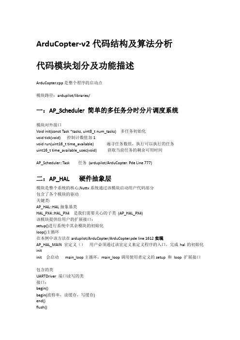
ArduCopter-v2代码结构及算法分析代码模块划分及功能描述ArduCopter.cpp是整个程序的启动点模块路径:ardupilot/libraries/一:AP_Scheduler 简单的多任务分时分片调度系统模块对外接口Void init(const Task *tasks, uint8_t num_tasks) 多任务初始化void tick(void) 控制计数值加1void run(uint16_t time_available) 遍寻任务数组,执行可以执行的任务uint16_t time_available_usec(void) 获取当前任务的剩余可用时间AP_Scheduler::Task 任务(ardupilot/ArduCopter. Pde Line 777)二:AP_HAL 硬件抽象层模块是整个系统的核心,Nuttx系统通过该模块启动用户代码部分包含了各个模块的驱动关键类:AP_HAL::HAL抽象基类HAL_PX4::HAL_PX4 是我们需要关心的子类(AP_HAL_PX4)该模块提供给用户的扩展接口:setup()进行系统中其余模块的初始化loop()主循环在本例中该方法在ardupilot/ArduCopter/ArduCopter.pde line 1612实现AP_HAL_MAIN 宏定义()用户必须通过该宏定义来定义程序的入口,完成hal的初始化initinit 会启动main_loop主循环,main_loop调用使用者定义的setup 和loop 扩展接口包含的类UARTDriver 端口读写的类接口:begin()begin(波特率,读缓存,写缓存)end()flush()set_blocking_writes()set_flow_control()get_flow_control()(1)PX4AnalogSource(2)PX4AnalogIn(3)PX4GPIO接口:Init()pinMode()analogPinToDigitalPin()read()write()toggle()channel()attach_interrupt()usb_connected()(5) PX4RCInput 遥控输入接口:void init(void* machtnichts);bool new_input(); 判断是否有新的输入到达uint8_t num_channels(); 获取RC输入通道个数uint16_t read(uint8_t ch); 读取指定通道的输入uint8_t read(uint16_t* periods, uint8_t len); 读取指定多个通道的输入bool set_overrides(int16_t *overrides, uint8_t len);bool set_override(uint8_t channel, int16_t override); 给指定通道设置假数据,如果该通道设置了假数据,则读取该通道的输入,始终读到的是设置的数据void clear_overrides();void _timer_tick(void); 循环调用每个tick更新一次input数据(4)PX4RCOutput 输出void init(void* machtnichts);void set_freq(uint32_t chmask, uint16_t freq_hz); 设置多个通道的输出频率,必须大于50uint16_t get_freq(uint8_t ch); 获取指定通道的输出频率void enable_ch(uint8_t ch); 最多8个通道void disable_ch(uint8_t ch);void write(uint8_t ch, uint16_t period_us); 单个通道写输出void write(uint8_t ch, uint16_t* period_us, uint8_t len); 多个通道写输出uint16_t read(uint8_t ch);void read(uint16_t* period_us, uint8_t len);void set_safety_pwm(uint32_t chmask, uint16_t period_us);void set_failsafe_pwm(uint32_t chmask, uint16_t period_us);void force_safety_off(void);void _timer_tick(void); 循环调用每个tick将output数据输出,电机、相机控制(5)PX4Storage(6)I2CDriverAP_HAL::UARTDriver* uartA; GCSAP_HAL::UARTDriver* uartB; GPSAP_HAL::UARTDriver* uartC; GCSAP_HAL::UARTDriver* uartD; GCSAP_HAL::UARTDriver* uartE; GPSAP_HAL::I2CDriver* i2c;AP_HAL::SPIDeviceManager* spi; 板载加速度计和磁罗盘、陀螺仪、空压表AP_HAL::AnalogIn* analogin; 电源输入AP_HAL::Storage* storage;AP_HAL::UARTDriver* console;AP_HAL::GPIO* gpio; 控制飞控板上的LED指示灯、蜂鸣器等显示AP_HAL::RCInput* rcin; 遥控器输入AP_HAL::RCOutput* rcout; 电机输出AP_HAL::Scheduler* scheduler;AP_HAL::Util* util;三:AP_Notify 根据飞机状态更新各种指示灯提示、告警模块对外接口init(bool enable_external_leds)对初始化,并对AP_BoardLED、ToshibaLED_PX4、ToneAlarm_PX4、ExternalLED、ToshibaLED_I2C、ExternalLED、ToshibaLED_I2C进行初始化void update(void)用户层可以通过该模块通知void AP_Notify::init(bool enable_external_leds) 初始化各种指示灯、蜂鸣器等等void AP_Notify::update(void) 各种指示灯根据flags标示进行更新状态四:AP_Vehicle仅仅是固定翼和螺旋飞机的通用参数结构体五:AP_GPS GPS相关库模块接口Init()Update()can_calculate_base_pos()calculate_base_pos()status() 查询gps状态Location &location(uint8_t instance)const Vector3f &velocity(uint8_t instance)velocity()float ground_speed(uint8_t instance)AP_GPS_Glitch.h中GPS_Glitch GPS干扰保护库添加了AP_GPS数据的判断对外接口:check_position() 判断GPS是否正常判断算法AP_GPS_Glitch.cpp支持的几种GPS协议AP_GPS_UBLOX 我们现在飞机应该装的这个AP_GPS_MTK19AP_GPS_MTKAP_GPS_SBPAP_GPS_SIRFAP_GPS_NMEAGPS模块结构:上层接口AP_GPS底层接口AP_GPS_Backendread() 接口,读取GPS数据,解析后统一填充到AP_GPS::GPS_State结构中,各种不同GPS会有不同的实现底层实现AP_GPS_UBLOX六:AP_Baro 气压计相关库PX4AP_Baro_PX4对外接口参考Healthy() 判断气压计能否正常工作bool init(); 初始化uint8_t read();float get_pressure(); 获取气压值float get_temperature(); 获取气温值get_altitude() 获取高度值calibrate() 校准气压计get_climb_rate() 获取爬升率DerivativeFilterstruct baro_report {float pressure;float altitude;float temperature;uint64_t timestamp;uint64_t error_count;};AP_Baro_Glitch.h 气压计干扰保护库check_alt() 判断气压计是否正常中Baro_Glitch支持几种类型的气压计AP_Baro_BMP085AP_Baro_HILAP_Baro_MS5611AP_Baro_PX4AP_Baro_VRBRAIN本例中使用的是AP_Baro_PX4七:AP_Compass_PX4 三轴罗盘相关库接口参考AP_Compass_PX4.h和Compass.hInit() 三轴罗盘初始化Read() 从罗盘驱动读取数据get_field() 获取罗盘数据八:AP_InertialSensor 惯性传感器主要接口:init( Start_style style, Sample_rate sample_rate) 加速度计和陀螺仪初始化update() 根据罗盘、加速度的._gyro_health 情况更新主陀螺仪、主加速度计get_gyro_drift_rate(void) 获取最大的陀螺漂移率get_accel() 获取加速度信息get_gyro() 获取陀螺仪信息AP_InertialSensor_Backend/AP_InertialSensor_PX4主要接口:Update()循环被调用,获取陀螺仪、加速度信息,并通过_rotate_and_offset_gyro() _rotate_and_offset_acce 对获取的信息做矩阵变换最终输出保留在_imu._gyro[instance]_imu._gyro_healthy[instance]_imu._accel[instance]_imu._accel_healthy[instance]中accel_sample_available() 判断加速度传感器可用gyro_sample_available() 判断陀螺仪传感器可用_rotate_and_offset_gyro(uint8_t instance, const Vector3f &gyro) gyro 为从陀螺仪获取的姿态数据{_imu._gyro[instance] = gyro;_imu._gyro[instance].rotate(_imu._board_orientation);_imu._gyro[instance] -= _imu._gyro_offset[instance];_imu._gyro_healthy[instance] = true;}_rotate_and_offset_accel(uint8_t instance, const Vector3f &accel){// accel 为从加速度计获取的加速度信息_imu._accel[instance] = accel;_imu._accel[instance].rotate(_imu._board_orientation);const Vector3f &accel_scale = _imu._accel_scale[instance].get();_imu._accel[instance].x *= accel_scale.x;_imu._accel[instance].y *= accel_scale.y;_imu._accel[instance].z *= accel_scale.z;_imu._accel[instance] -= _imu._accel_offset[instance];_imu._accel_healthy[instance] = true;}_set_accel_error_count() 从陀螺仪、加速度计获取error信息_set_gyro_error_count()_default_filter()属性:AP_InertialSensor &_imu;九:AP_AHRS Attitude Heading Reference System 航姿系统AP_AHRS_DCMAP_AHRS_NavEKF采用DCM(方向余弦矩阵方法)或EKF(扩展卡尔曼滤波方法)预估飞行器姿态姿态和方位参考系统综合惯性传感器、气压采样、gps进行姿态和方位管理接口:AP_AHRS_NavEKF(AP_InertialSensor &ins, AP_Baro &baro, AP_GPS &gps)Init() 设置ins、compass的反向AP_AHRSset_compass(Compass *compass) 设置磁罗盘set_airspeed(AP_Airspeed *airspeed)get_accel_ef(void) 获取加速度计的值in earth frameairspeed_estimate() 预估空速AP_AHRS_NavEKFadd_trim(….) 调整-trim roll 、pitchgroundspeed_vector() 预估飞机相对地面的水平速度update_trig(void) 根据dcm旋转矩阵更新cos_yaw、sina_yaw、cos_roll、sina_roll、sina_yaw、cos_yawupdate_cd_values(void) 根据roll、yaw、pitch更新roll_sensor、yaw_sensor、pitch_sensor get_gyro(void) 获取漂移校准的陀螺矢量get_gyro_drift(void)get_position(struct Location &loc) 获取当前位置,高度通过气压计计算,gpseuler_angles(void) 计算欧拉角、方向矩阵estimate_wind() 预估风速get_dcm_matrix(void) 获取方向余弦矩阵get_error_rp(void)get_error_yaw(void)update() 更新数据AP_Airspeed十:AP_Mission 结合AP_AHRS进行飞行任务管理十一:AP_RangeFinder 声呐或红外测距传感器的交互库十二:RCMapper通道映射,保存了roll、pitch、yaw、throttle的输入通道ID十三:AP_BoardConfig十四:AP_BattMonitor 电源模块管理十五:AP_Frsky_Telem十六:AP_InertialNav\AP_InertialNav_NavEKF 扩展带有gps和气压计数据的惯性导航库接口:get_altitude() 获取高度信息get_velocity_z() 获取z轴上的速度get_longitude() 获取基于经度的加速度get_latitude() 获取基于纬度的加速度get_latitude_diff()get_longitude_diff()get_velocity_xy() 设置在经度和纬度方向的速度十七:AC_AttitudeControl_Heli/AC_AttitudeControl 航姿控制相关库属性:_angle_ef_target模块接口:rate_controller_run()angle_ef_roll_pitch_rate_ef_yaw_smooth()frame_conversion_ef_to_bf(const Vector3f& ef_vector, Vector3f& bf_vector) 世界坐标转换到体坐标frame_conversion_bf_to_ef (const Vector3f& bf_vector, Vector3f& ef_vector) 体坐标系转换到世界坐标系relax_bf_rate_controller()set_yaw_target_to_current_heading() 设置目标航线为当前方向set_throttle_out()angle_ef_roll_pitch_rate_ef_yaw_smooth()set_throttle_out()十八:AC_PosControl 位置控制模块模块接口:AC_PosControl(const AP_AHRS& ahrs, const AP_InertialNav& inav, const AP_Motors& motors, AC_AttitudeControl& attitude_control,AC_P& p_alt_pos, AC_P& p_alt_rate, AC_PID& pid_alt_accel, AC_P& p_pos_xy, AC_PID& pid_rate_lat, AC_PID& pid_rate_lon)set_alt_target() 设置目标高度set_dt(float delta_sec) 设置时间间隔set_alt_max(float alt) 设置最大的高度set_speed_z(float speed_down, float speed_up) 设置最大的爬升和下降速度set_accel_z(float accel_cmss) 设置垂直加速度set_alt_target_with_slew() 调整目标高度为最终目标set_alt_target_from_climb_rate() 通过爬升速率、时间调整目标高度get_alt_error() 返回高度误差get_stopping_point_z() 计算停止点高度init_takeoff() 起飞前初始化高度calc_leash_length()lean_angles_to_accel() 将角度转换为加速度accel_to_lean_angles() 将水平方向的期望转换为roll、pitch的角度init_vel_controller_xyz()update_vel_controller_xyz()init_xy_controller()update_xy_controller()update_z_controller()属性:_dt 时间间隔_alt_max 距离home位置的最大高度_speed_up_cms 最大的爬升速率cm/s_speed_down_cms 最大的下降速率cm/s_accel_z_cms 最大垂直加速度_accel_cms 最大水平加速度_speed_cms 最大水平速度_leash; 水平误差_leash_down_z 向下误差_leash_up_z 向上误差_throttle_hover 估算的油门输出值_pos_target 目标位置_last_update_xy_ms 上次执行update_xy_controller的时间_last_update_z_ms 上次执行update_z_controller的时间_last_update_vel_xyz_ms 上次执行update_vel_controller_xyz的时间_roll_target 输出的roll值_pitch_target 输出的pitch值十九:AP_Motors / AP_MotorsMatrix 多旋翼和传统直升机混合的电机库接口:Init() 初始化set_update_rate() 设置输出频率set_frame_orientation()enable() 安全开关output() 输出数据的接口,设置各个电机的valueset_roll(int16_t roll_in) Motors的对外接口,AC通过该接口设置计算出来的值set_pitch(int16_t pitch_in)set_yaw(int16_t yaw_in)set_throttle(int16_t throttle_in)二十:AC_WPNav 在loiter等模式中使用接口函数:AC_WPNav(const AP_InertialNav& inav, const AP_AHRS& ahrs, AC_PosControl& pos_control)init_loiter_target() 初始化当前位置和速度update_loiter()get_yaw()get_roll()get_pitch()二十一:AC_Circle 在Circle模式中使用设置飞机飞行的范围参数原点、半径,然后每次循环根据当前位置计算下一个点的roll、pitch、yaw接口函数:init(const Vector3f& center)init()update()get_roll()get_pitch()get_yaw()二十二:AP_Relay二十三:AP_ServoRelayEvents二十四:AP_Param 运行时参数管理,配置参数的读写二十五:StorageManager/StorageAccess/PX4Storage提供了对hal->Storage进行读写封装二十六:AC_PIDPID算法库主要接口函数:get_p(float error) 计算比例放大分量get_i(float error, float dt) 计算积分放大分量get_d(float input, float dt) 计算微分放大分量get_pi(float error, float dt) 计算比例放大和积分放大分量get_pid(float error, float dt) 计算PID值AC_P 计算比例放大分量的库主要接口函数:get_p(float error) 计算比例放大分量AP_Mission:从eeprom(电可擦只读存储器)存储/读取飞行指令相关库AP_Buffer:惯性导航时所用到的一个简单的堆栈(FIFO,先进先出)缓冲区AP_Mount,AP_Camera, AP_Relay:相机安装控制库,相机快门控制库保持飞机速度始终始终不超过设置的最小速度API接口:void enable(bool true_false)bool enabled() //设置和判断控制速度功能是否可用void test_pump(bool true_false) //主要用于控制速度功能测试void set_pump_rate(float pct_at_1ms) //设置速度调整的参数void update(); // 被循环调用,不停的判断飞机速度是否超过设置的最小速度。

Pixhawk多轴使用说明书(V1.4.2)乐迪Pixhawk飞控四轴(ArduCopter)版本信息介绍V1版本:完善基本操作说明V1.1版本:添加失控保护介绍V1.3版本:添加日志,EKF失控保护的介绍V1.4版本:飞行模式和解锁故障保护的详细介绍V1.4.1版本:完善电流计设置V1.4.2版本:修改.net、MP的下载链接、修改罗盘的校准方法简介非常感谢您购买深圳市乐迪电子有限公司生产的pixhawk飞控。
Pixhawk自动驾驶仪(简称pix)是一款非常优秀而且完全开源的自动驾驶控制器,他的前世就是大名鼎鼎的APM,由于APM的处理器已经接近满负荷,没有办法满足更复杂的运算处理,所以硬件厂商采用了目前最新标准的32位ARM处理器,第一代产品是PX4系列,他分为飞控处理器PX4FMU和输入输出接口板PX4IO。
PX4系列可以单独使用PX4FMU(但是接线很复杂),也可以配合输入输出接口板PX4IO来使用,但是因为没有统一的外壳,不好固定,再加上使用复杂,所以基本上属于一代实验版本。
通过PX4系列的经验,厂商终于简化了结构,把PX4FMU和PX4IO整合到一块板子上,并加上了骨头形状的外壳,优化了硬件和走线,也就是这款第二代产品Pixhawk。
可应用于固定翼、直升机、多旋翼、地面车辆等,建议:在您阅读本说明书时,边阅读边操作。
您在阅读这些说明时,如遇到困难请查阅本说明书或致电我们售后(0755-********)及登陆航模类论坛(如:/forum.php?mod=forumdisplay&fid=277泡泡老师教程,,航模吧,乐迪微信公众平台,乐迪官方群:334960324)查看相关问题问答。
乐迪微信公众平台乐迪官方群售后服务条款1,本条款仅适用于深圳市乐迪电子有限公司所生产的产品,乐迪通过其授权经销商销售的产品亦适用本条款。
2,乐迪产品自购买之日起,一周内经我司核实为质量问题,由乐迪承担返修产品的往返快递费,购买乐迪产品超过一周到一年内经我司核实为质量问题,用户和乐迪各自承担寄出返修产品的快递费。
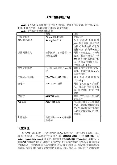
APM飞控系统介绍APM飞控系统是国外的一个开源飞控系统,能够支持固定翼,直升机,3轴,4轴,6轴飞行器。
在此我只介绍固定翼飞控系统。
飞控原理在APM飞控系统中,采用的是两级PID控制方式,第一级是导航级,第二级是控制级,导航级的计算集中在medium_loop( ) 和fastloop( )的update_current_flight_mode( )函数中,控制级集中在fastloop( )的stabilize( )函数中。
导航级PID控制就是要解决飞机如何以预定空速飞行在预定高度的问题,以及如何转弯飞往目标问题,通过算法给出飞机需要的俯仰角、油门和横滚角,然后交给控制级进行控制解算。
控制级的任务就是依据需要的俯仰角、油门、横滚角,结合飞机当前的姿态解算出合适的舵机控制量,使飞机保持预定的俯仰角,横滚角和方向角。
最后通过舵机控制级set_servos_4( )将控制量转换成具体的pwm信号量输出给舵机。
值得一提的是,油门的控制量是在导航级确定的。
控制级中不对油门控制量进行解算,而直接交给舵机控制级。
而对于方向舵的控制,导航级并不给出方向舵量的解算,而是由控制级直接解算方向舵控制量,然后再交给舵机控制级。
以下,我剔除了APM飞控系统的细枝末节,仅仅将飞控系统的重要语句展现,只浅显易懂地说明APM飞控系统的核心工作原理。
一,如何让飞机保持预定高度和空速飞行要想让飞机在预定高度飞行,飞控必须控制好飞机的升降舵和油门,因此,首先介绍固定翼升降舵和油门的控制,固定翼的升降舵和油门控制方式主要有两种:一种是高度控制油门,空速控制升降舵方式。
实际飞行存在四种情况,第一种情况是飞机飞行过程中,如果高度低于目标高度,飞控就会控制油门加大,从而导致空速加大,然后才导致拉升降舵,飞机爬升;第二种情况与第一种情况相反;第三种情况是飞机在目标高度,但是空速高于目标空速,这种情况飞控会直接拉升降舵,使飞机爬升,降低空速,但是,高度增加了,飞控又会减小油门,导致空速降低,空速低于目标空速后,飞控推升降舵,导致飞机降低高度。

ArduPilot Mega 说明书这里是 ArduPlane wiki,内容包括所有的组装和使用说明。
请使用侧边栏的功能导览。
注意: 如果要找 ArduCopter 的操作说明,请到这里。
? ? ? ? ? ? ? 介绍项目历史项目新闻购买说明书快速入门指南 o APM 2 快速入门指南 o APM 1 快速入门指南设置 o APM2 ? ? ? ? APM 2 板下载及安装 Mission Planner 和飞行软件连接遥控设备首次设置 ? ? o APM 1 ? ? ? ? 组装下载与安装 Mission Planner 及其他飞行软件连接遥控设备首次设置 ? ? 检查传感器逆转舵机和设置普通/升降副翼模式 ? ? ? 飞行 o o APM 开机和校准调整 ArduPlane ? ? ? ? 常用飞机的配置文件 MAVLink 参数说明进阶设定使用地面控制站 ? Mission Planner 使用任务规划器使用硬件开关检查传感器逆转舵机和设置普通/升降副翼模式?HappyKillmore 地面站 QGroundControl ? ? 航点 Widget 参数 Widgeto使用任务规划工具规划和分析任务 ? ? ? ? ? ? ? ? ? 规划航点和任务使用地面站录制和播放任务下载和分析飞行数据配置 PID 使用串口终端与 PC 飞行仿真器交互Python scripting 其他特性增稳模式线控模式自动驾驶模式返航模式(RTL) 盘旋模式o飞行模式 ? ? ? ? ?ooooo ? 模拟 o oo ?使用数据记录器自动起飞和降落启用倒飞设置地理围栏线性飞行的最低高度限制使用 X-Plane 进行半硬件仿真使用 FlightGear 仿真器使用软件再环仿真器可选附件 o 使用无线遥测数据和飞行实时命令 ? APM 1 ? ? ? APM 2 ? ? o ooooooooooo 空速计电压和电流传感器自动襟翼磁力仪简单的相机控制使用游戏游戏杆替代遥控自动相机追踪多副翼通道其他模拟传感器其他 I2C 传感器 3DR Radio Xbee 3DR Radio XbeeOn-screen display (光流传感器)用命令解析器进行高级设置和测试 ? ? 设置飞行模式测试模式 ? ? ? ? ? ? ? ? ? ? ? ? ? ? ? ? ? ? 遥控输入 GPS 输入 IMU 输出陀螺和加速度传感器输入电池输入(可选) 继电器输出航路显示空速计输出(可选) 绝对气压(高度)传感器输出磁力计输出(可选) Xbee 测试(可选) 导出 EEPROM GPS 原始输入日志指南空速计指南 Xbee 指南电压传感器指南高级设置? ?疑难解答 o 疑难解答附录 o oooo 正确的 LED 行为设置 RC 发射器的 6 种模式失效保护功能命令提示符 (CLI) 设置和测试使用 Arduino 编程 ? ? ? o ooooo 设置编程环境使用 Arduino 为 APM 编程下载和使用 APM 软件 ? 设置选项使用 AVR Studio 刻录程序理解状态/诊断串口输出理解偏航距 APM MAV 命令使用调试终端地面站重刷/更新 GPS 固件 ? ? ? uBlox GPS MediaTek GPS 其他 GPS 模块 APM 2 APM 1 ? ? 使用 AVRStudio 为编码器重建/编程使用 Bus Pirate 为编码器编程o更新 PPM encoder 轫体 ? ?ooAPM 硬件技术细节 ArduPilot Mega 主板ArduPilot Mega IMU 传感器板 APM 代码贡献者指南 ? 使用 Git ? ? ? ? ? ? ? ? 逐步引导使用 Git 贡献代码使用 Git 命令行使用 Git 扩展工具使用 TortoiseGit代码规范使用 Eclipse 编译 ArduPilot Mega 使用 make 编译 ArduPilot Mega 使用JTAG 调试 ArduPilot Megao ? ? 词汇表教学图片来源The DIY Drones Dev Team介绍欢迎使用 ArduPlane 操作说明,此说明会告诉你如何将一般的遥控飞机变为自动驾驶的无人机。
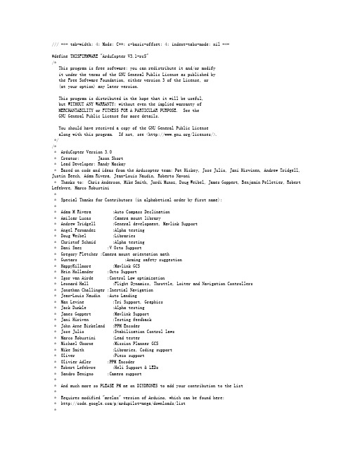
/// -*- tab-width: 4; Mode: C++; c-basic-offset: 4; indent-tabs-mode: nil -*-#define THISFIRMWARE "ArduCopter V3.1-rc5"/*This program is free software: you can redistribute it and/or modifyit under the terms of the GNU General Public License as published bythe Free Software Foundation, either version 3 of the License, or(at your option) any later version.This program is distributed in the hope that it will be useful,but WITHOUT ANY WARRANTY; without even the implied warranty ofMERCHANTABILITY or FITNESS FOR A PARTICULAR PURPOSE. See theGNU General Public License for more details.You should have received a copy of the GNU General Public Licensealong with this program. If not, see </licenses/>.*//** ArduCopter Version 3.0* Creator: Jason Short* Lead Developer: Randy Mackay* Based on code and ideas from the Arducopter team: Pat Hickey, Jose Julio, Jani Hirvinen, Andrew Tridgell, Justin Beech, Adam Rivera, Jean-Louis Naudin, Roberto Navoni* Thanks to: Chris Anderson, Mike Smith, Jordi Munoz, Doug Weibel, James Goppert, Benjamin Pelletier, Robert Lefebvre, Marco Robustini** Special Thanks for Contributors (in alphabetical order by first name):** Adam M Rivera :Auto Compass Declination* Amilcar Lucas :Camera mount library* Andrew Tridgell :General development, Mavlink Support* Angel Fernandez :Alpha testing* Doug Weibel :Libraries* Christof Schmid :Alpha testing* Dani Saez :V Octo Support* Gregory Fletcher :Camera mount orientation math* Guntars :Arming safety suggestion* HappyKillmore :Mavlink GCS* Hein Hollander :Octo Support* Igor van Airde :Control Law optimization* Leonard Hall :Flight Dynamics, Throttle, Loiter and Navigation Controllers* Jonathan Challinger :Inertial Navigation* Jean-Louis Naudin :Auto Landing* Max Levine :Tri Support, Graphics* Jack Dunkle :Alpha testing* James Goppert :Mavlink Support* Jani Hiriven :Testing feedback* John Arne Birkeland :PPM Encoder* Jose Julio :Stabilization Control laws* Marco Robustini :Lead tester* Michael Oborne :Mission Planner GCS* Mike Smith :Libraries, Coding support* Oliver :Piezo support* Olivier Adler :PPM Encoder* Robert Lefebvre :Heli Support & LEDs* Sandro Benigno :Camera support** And much more so PLEASE PM me on DIYDRONES to add your contribution to the List** Requires modified "mrelax" version of Arduino, which can be found here:* /p/ardupilot-mega/downloads/list*////////////////////////////////////////////////////////////////////////////////// Header includes////////////////////////////////////////////////////////////////////////////////#include <math.h>#include <stdio.h>#include <stdarg.h>// Common dependencies#include <AP_Common.h>#include <AP_Progmem.h>#include <AP_Menu.h>#include <AP_Param.h>// AP_HAL#include <AP_HAL.h>#include <AP_HAL_AVR.h>#include <AP_HAL_AVR_SITL.h>#include <AP_HAL_PX4.h>#include <AP_HAL_FLYMAPLE.h>#include <AP_HAL_Linux.h>#include <AP_HAL_Empty.h>// Application dependencies#include <GCS_MAVLink.h> // MAVLink GCS definitions#include <AP_GPS.h> // ArduPilot GPS library#include <AP_GPS_Glitch.h> // 全球定位系统干扰保护库#include <DataFlash.h> // ArduPilot Mega Flash Memory Library#include <AP_ADC.h> // ArduPilot Mega Analog to Digital Converter Library#include <AP_ADC_AnalogSource.h>#include <AP_Baro.h>#include <AP_Compass.h> // ArduPilot Mega Magnetometer Library#include <AP_Math.h> // ArduPilot Mega Vector/Matrix math Library#include <AP_Curve.h> // Curve used to linearlise throttle pwm to thrust#include <AP_InertialSensor.h> // ArduPilot Mega Inertial Sensor (accel & gyro) Library #include <AP_AHRS.h>#include <APM_PI.h> // PI library#include <AC_PID.h> // PID library#include <RC_Channel.h> //遥控通道库#include <AP_Motors.h> // AP Motors library#include <AP_RangeFinder.h> // Range finder library#include <AP_OpticalFlow.h> // Optical Flow library#include <Filter.h> // Filter library#include <AP_Buffer.h> // APM FIFO Buffer#include <AP_Relay.h> // APM relay#include <AP_Camera.h> // Photo or video camera#include <AP_Mount.h> // Camera/Antenna mount#include <AP_Airspeed.h> // needed for AHRS build#include <AP_Vehicle.h> // needed for AHRS build#include <AP_InertialNav.h> // ArduPilot Mega inertial 导航 library#include <AC_WPNav.h> // ArduCopter waypoint navigation library#include <AP_Declination.h> // ArduPilot Mega Declination Helper Library#include <AC_Fence.h> // Arducopter Fence library#include <memcheck.h> // memory limit checker#include <SITL.h> // software in the loop support#include <AP_Scheduler.h> // 主循环调度程序#include <AP_RCMapper.h> // RC input mapping library#include <AP_Notify.h> // Notify library#include <AP_BattMonitor.h> // Battery monitor library#if SPRAYER == ENABLED#include <AC_Sprayer.h> // crop sprayer library// AP_HAL to Arduino compatibility layer#include "compat.h"// Configuration#include "defines.h"#include "config.h"#include "config_channels.h"// Local modules#include "Parameters.h"#include "GCS.h"//////////////////////////////////////////////////////////////////////////////// // cliSerial//////////////////////////////////////////////////////////////////////////////// // cliSerial isn't strictly necessary - it is an alias for hal.console. It may // be deprecated in favor of hal.console in later releases.static AP_HAL::BetterStream* cliSerial;// N.B. we need to keep a static declaration which isn't guarded by macros// at the top to cooperate with the prototype mangler.//////////////////////////////////////////////////////////////////////////////// // AP_HAL instance//////////////////////////////////////////////////////////////////////////////// const AP_HAL::HAL& hal = AP_HAL_BOARD_DRIVER;//////////////////////////////////////////////////////////////////////////////// // Parameters//////////////////////////////////////////////////////////////////////////////// //// Global parameters are all contained within the 'g' class.//static Parameters g;// main loop schedulerstatic AP_Scheduler scheduler;// AP_Notify instancestatic AP_Notify notify;//////////////////////////////////////////////////////////////////////////////// // prototypes//////////////////////////////////////////////////////////////////////////////// static void update_events(void);static void print_flight_mode(AP_HAL::BetterStream *port, uint8_t mode);//////////////////////////////////////////////////////////////////////////////// // Dataflash//////////////////////////////////////////////////////////////////////////////// #if CONFIG_HAL_BOARD == HAL_BOARD_APM2static DataFlash_APM2 DataFlash;#elif CONFIG_HAL_BOARD == HAL_BOARD_APM1static DataFlash_APM1 DataFlash;#elif CONFIG_HAL_BOARD == HAL_BOARD_AVR_SITL//static DataFlash_File DataFlash("/tmp/APMlogs");static DataFlash_SITL DataFlash;#elif CONFIG_HAL_BOARD == HAL_BOARD_PX4static DataFlash_File DataFlash("/fs/microsd/APM/logs");#elif CONFIG_HAL_BOARD == HAL_BOARD_LINUXstatic DataFlash_File DataFlash("logs");#elsestatic DataFlash_Empty DataFlash;#endif////////////////////////////////////////////////////////////////////////////////// the rate we run the main loop at////////////////////////////////////////////////////////////////////////////////static const AP_InertialSensor::Sample_rate ins_sample_rate = AP_InertialSensor::RATE_100HZ;////////////////////////////////////////////////////////////////////////////////// Sensors//////////////////////////////////////////////////////////////////////////////////// There are three basic options related to flight sensor selection.//// - Normal flight mode. Real sensors are used.// - HIL Attitude mode. Most sensors are disabled, as the HIL// protocol supplies attitude information directly.// - HIL Sensors mode. Synthetic sensors are configured that// supply data from the simulation.//// All GPS access should be through this pointer.static GPS *g_gps;static GPS_Glitch gps_glitch(g_gps);// flight modes convenience arraystatic AP_Int8 *flight_modes = &g.flight_mode1;#if HIL_MODE == HIL_MODE_DISABLED#if CONFIG_ADC == ENABLEDstatic AP_ADC_ADS7844 adc;#endif#if CONFIG_IMU_TYPE == CONFIG_IMU_MPU6000static AP_InertialSensor_MPU6000 ins;#elif CONFIG_IMU_TYPE == CONFIG_IMU_OILPANstatic AP_InertialSensor_Oilpan ins(&adc);#elif CONFIG_IMU_TYPE == CONFIG_IMU_SITLstatic AP_InertialSensor_HIL ins;#elif CONFIG_IMU_TYPE == CONFIG_IMU_PX4static AP_InertialSensor_PX4 ins;#elif CONFIG_IMU_TYPE == CONFIG_IMU_FLYMAPLEAP_InertialSensor_Flymaple ins;#elif CONFIG_IMU_TYPE == CONFIG_IMU_L3G4200DAP_InertialSensor_L3G4200D ins;#endif#if CONFIG_HAL_BOARD == HAL_BOARD_AVR_SITL// When building for SITL we use the HIL barometer and compass driversstatic AP_Baro_HIL barometer;static AP_Compass_HIL compass;static SITL sitl;#else// Otherwise, instantiate a real barometer and compass driver#if CONFIG_BARO == AP_BARO_BMP085static AP_Baro_BMP085 barometer;#elif CONFIG_BARO == AP_BARO_PX4static AP_Baro_PX4 barometer;#elif CONFIG_BARO == AP_BARO_MS5611#if CONFIG_MS5611_SERIAL == AP_BARO_MS5611_SPIstatic AP_Baro_MS5611 barometer(&AP_Baro_MS5611::spi);#elif CONFIG_MS5611_SERIAL == AP_BARO_MS5611_I2Cstatic AP_Baro_MS5611 barometer(&AP_Baro_MS5611::i2c);#else#error Unrecognized CONFIG_MS5611_SERIAL setting.#endif#endif#if CONFIG_HAL_BOARD == HAL_BOARD_PX4static AP_Compass_PX4 compass;#elsestatic AP_Compass_HMC5843 compass;#endif#endif// real GPS selection#if GPS_PROTOCOL == GPS_PROTOCOL_AUTOAP_GPS_Auto g_gps_driver(&g_gps);#elif GPS_PROTOCOL == GPS_PROTOCOL_NMEAAP_GPS_NMEA g_gps_driver;#elif GPS_PROTOCOL == GPS_PROTOCOL_SIRFAP_GPS_SIRF g_gps_driver;#elif GPS_PROTOCOL == GPS_PROTOCOL_UBLOXAP_GPS_UBLOX g_gps_driver;#elif GPS_PROTOCOL == GPS_PROTOCOL_MTKAP_GPS_MTK g_gps_driver;#elif GPS_PROTOCOL == GPS_PROTOCOL_MTK19AP_GPS_MTK19 g_gps_driver;#elif GPS_PROTOCOL == GPS_PROTOCOL_NONEAP_GPS_None g_gps_driver;#else#error Unrecognised GPS_PROTOCOL setting.#endif // GPS PROTOCOLstatic AP_AHRS_DCM ahrs(&ins, g_gps);#elif HIL_MODE == HIL_MODE_SENSORS// sensor emulatorsstatic AP_ADC_HIL adc;static AP_Baro_HIL barometer;static AP_Compass_HIL compass;static AP_GPS_HIL g_gps_driver;static AP_InertialSensor_HIL ins;static AP_AHRS_DCM ahrs(&ins, g_gps);#if CONFIG_HAL_BOARD == HAL_BOARD_AVR_SITL// When building for SITL we use the HIL barometer and compass drivers static SITL sitl;#endif#elif HIL_MODE == HIL_MODE_ATTITUDEstatic AP_ADC_HIL adc;static AP_InertialSensor_HIL ins;static AP_AHRS_HIL ahrs(&ins, g_gps);static AP_GPS_HIL g_gps_driver;static AP_Compass_HIL compass; // never usedstatic AP_Baro_HIL barometer;#if CONFIG_HAL_BOARD == HAL_BOARD_AVR_SITL// When building for SITL we use the HIL barometer and compass driversstatic SITL sitl;#endif#else#error Unrecognised HIL_MODE setting.#endif // HIL MODE////////////////////////////////////////////////////////////////////////////////// Optical flow sensor////////////////////////////////////////////////////////////////////////////////#if OPTFLOW == ENABLEDstatic AP_OpticalFlow_ADNS3080 optflow;#elsestatic AP_OpticalFlow optflow;#endif////////////////////////////////////////////////////////////////////////////////// GCS selection////////////////////////////////////////////////////////////////////////////////static GCS_MAVLINK gcs0;static GCS_MAVLINK gcs3;////////////////////////////////////////////////////////////////////////////////// SONAR selection//////////////////////////////////////////////////////////////////////////////////ModeFilterInt16_Size3 sonar_mode_filter(1);#if CONFIG_SONAR == ENABLEDstatic AP_HAL::AnalogSource *sonar_analog_source;static AP_RangeFinder_MaxsonarXL *sonar;#endif////////////////////////////////////////////////////////////////////////////////// User variables////////////////////////////////////////////////////////////////////////////////#ifdef USERHOOK_VARIABLES#include USERHOOK_VARIABLES#endif////////////////////////////////////////////////////////////////////////////////// Global variables/////////////////////////////////////////////////////////////////////////////////* Radio values* Channel assignments* 1 Ailerons (rudder if no ailerons)* 2 Elevator* 3 Throttle* 4 Rudder (if we have ailerons)* 5 Mode - 3 position switch* 6 User assignable* 7 trainer switch - sets throttle nominal (toggle switch), sets accels to Level (hold >1 second)* 8 TBD* Each Aux channel can be configured to have any of the available auxiliary functions assigned to it.* See libraries/RC_Channel/RC_Channel_aux.h for more information*///Documentation of GLobals:static union {struct {uint8_t home_is_set : 1; // 0uint8_t simple_mode : 2; // 1,2 // This is the state of simple mode : 0 = disabled ; 1 = SIMPLE ;2 = SUPERSIMPLEuint8_t pre_arm_rc_check : 1; // 3 // true if rc input pre-arm checks have been completed successfully uint8_t pre_arm_check : 1; // 4 // true if all pre-arm checks (rc, accel calibration, gps lock) have been performeduint8_t auto_armed : 1; // 5 // stops auto missions from beginning until throttle is raised uint8_t logging_started : 1; // 6 // true if dataflash logging has starteduint8_t do_flip : 1; // 7 // Used to enable flip codeuint8_t takeoff_complete : 1; // 8uint8_t land_complete : 1; // 9 // true if we have detected a landinguint8_t new_radio_frame : 1; // 10 // Set true if we have new PWM data to act on from the Radio uint8_t CH7_flag : 2; // 11,12 // ch7 aux switch : 0 is low or false, 1 is center or true, 2 is highuint8_t CH8_flag : 2; // 13,14 // ch8 aux switch : 0 is low or false, 1 is center or true, 2 is highuint8_t usb_connected : 1; // 15 // true if APM is powered from USB connectionuint8_t yaw_stopped : 1; // 16 // Used to manage the Yaw hold capabilitiesuint8_t disable_stab_rate_limit : 1; // 17 // disables limits rate request from the stability controlleruint8_t rc_receiver_present : 1; // 18 // true if we have an rc receiver present (i.e. if we've ever received an update};uint32_t value;} ap;////////////////////////////////////////////////////////////////////////////////// Radio////////////////////////////////////////////////////////////////////////////////// This is the state of the flight control system// There are multiple states defined such as STABILIZE, ACRO,static int8_t control_mode = STABILIZE;// Used to maintain the state of the previous control switch position// This is set to -1 when we need to re-read the switchstatic uint8_t oldSwitchPosition;static RCMapper rcmap;// receiver RSSIstatic uint8_t receiver_rssi;////////////////////////////////////////////////////////////////////////////////// Failsafe////////////////////////////////////////////////////////////////////////////////static struct {uint8_t rc_override_active : 1; // 0 // true if rc control are overwritten by ground stationuint8_t radio : 1; // 1 // A status flag for the radio failsafeuint8_t battery : 1; // 2 // A status flag for the battery failsafeuint8_t gps : 1; // 3 // A status flag for the gps failsafeuint8_t gcs : 1; // 4 // A status flag for the ground station failsafeint8_t radio_counter; // number of iterations with throttle below throttle_fs_valueuint32_t last_heartbeat_ms; // the time when the last HEARTBEAT message arrived from a GCS - used for triggering gcs failsafe} failsafe;////////////////////////////////////////////////////////////////////////////////// Motor Output////////////////////////////////////////////////////////////////////////////////#if FRAME_CONFIG == QUAD_FRAME#define MOTOR_CLASS AP_MotorsQuad#elif FRAME_CONFIG == TRI_FRAME#define MOTOR_CLASS AP_MotorsTri#elif FRAME_CONFIG == HEXA_FRAME#define MOTOR_CLASS AP_MotorsHexa#elif FRAME_CONFIG == Y6_FRAME#define MOTOR_CLASS AP_MotorsY6#elif FRAME_CONFIG == OCTA_FRAME#define MOTOR_CLASS AP_MotorsOcta#elif FRAME_CONFIG == OCTA_QUAD_FRAME#define MOTOR_CLASS AP_MotorsOctaQuad#elif FRAME_CONFIG == HELI_FRAME#define MOTOR_CLASS AP_MotorsHeli#else#error Unrecognised frame type#endif#if FRAME_CONFIG == HELI_FRAME // helicopter constructor requires more argumentsstatic MOTOR_CLASS motors(&g.rc_1, &g.rc_2, &g.rc_3, &g.rc_4, &g.rc_8, &g.heli_servo_1, &g.heli_servo_2,&g.heli_servo_3, &g.heli_servo_4);#elif FRAME_CONFIG == TRI_FRAME // tri constructor requires additional rc_7 argument to allow tail servo reversing static MOTOR_CLASS motors(&g.rc_1, &g.rc_2, &g.rc_3, &g.rc_4, &g.rc_7);#elsestatic MOTOR_CLASS motors(&g.rc_1, &g.rc_2, &g.rc_3, &g.rc_4);#endif////////////////////////////////////////////////////////////////////////////////// PIDs////////////////////////////////////////////////////////////////////////////////// This is a convienience accessor for the IMU roll rates. It's currently the raw IMU rates// and not the adjusted omega rates, but the name is stuckstatic Vector3f omega;// This is used to hold radio tuning values for in-flight CH6 tuningfloat tuning_value;// used to limit the rate that the pid controller output is logged so that it doesn't negatively affect performance static uint8_t pid_log_counter;////////////////////////////////////////////////////////////////////////////////// LED output////////////////////////////////////////////////////////////////////////////////// Blinking indicates GPS statusstatic uint8_t copter_leds_GPS_blink;// Blinking indicates battery statusstatic uint8_t copter_leds_motor_blink;// Navigation confirmation blinksstatic int8_t copter_leds_nav_blink;////////////////////////////////////////////////////////////////////////////////// GPS variables////////////////////////////////////////////////////////////////////////////////// This is used to scale GPS values for EEPROM storage// 10^7 times Decimal GPS means 1 == 1cm// This approximation makes calculations integer and it's easy to readstatic const float t7 = 10000000.0;// We use atan2 and other trig techniques to calaculate angles// We need to scale the longitude up to make these calcs work// to account for decreasing distance between lines of longitude away from the equatorstatic float scaleLongUp = 1;// Sometimes we need to remove the scaling for distance calcsstatic float scaleLongDown = 1;////////////////////////////////////////////////////////////////////////////////// Location & Navigation////////////////////////////////////////////////////////////////////////////////// This is the angle from the copter to the next waypoint in centi-degreesstatic int32_t wp_bearing;// The original bearing to the next waypoint. used to point the nose of the copter at the next waypoint static int32_t original_wp_bearing;// The location of home in relation to the copter in centi-degreesstatic int32_t home_bearing;// distance between plane and home in cmstatic int32_t home_distance;// distance between plane and next waypoint in cm.static uint32_t wp_distance;// navigation mode - options include NAV_NONE, NAV_LOITER, NAV_CIRCLE, NAV_WPstatic uint8_t nav_mode;// Register containing the index of the current navigation command in the mission scriptstatic int16_t command_nav_index;// Register containing the index of the previous navigation command in the mission script// Used to manage the execution of conditional commandsstatic uint8_t prev_nav_index;// Register containing the index of the current conditional command in the mission scriptstatic uint8_t command_cond_index;// Used to track the required WP navigation information// options include// NAV_ALTITUDE - have we reached the desired altitude?// NAV_LOCATION - have we reached the desired location?// NAV_DELAY - have we waited at the waypoint the desired time?static float lon_error, lat_error; // Used to report how many cm we are from the next waypoint or loiter target positionstatic int16_t control_roll;static int16_t control_pitch;static uint8_t rtl_state; // records state of rtl (initial climb, returning home, etc)static uint8_t land_state; // records state of land (flying to location, descending)////////////////////////////////////////////////////////////////////////////////// Orientation////////////////////////////////////////////////////////////////////////////////// Convienience accessors for commonly used trig functions. These values are generated// by the DCM through a few simple equations. They are used throughout the code where cos and sin// would normally be used.// The cos values are defaulted to 1 to get a decent initial value for a level statestatic float cos_roll_x = 1.0;static float cos_pitch_x = 1.0;static float cos_yaw = 1.0;static float sin_yaw;static float sin_roll;static float sin_pitch;////////////////////////////////////////////////////////////////////////////////// SIMPLE Mode////////////////////////////////////////////////////////////////////////////////// Used to track the orientation of the copter for Simple mode. This value is reset at each arming// or in SuperSimple mode when the copter leaves a 20m radius from home.static float simple_cos_yaw = 1.0;static float simple_sin_yaw;static int32_t super_simple_last_bearing;static float super_simple_cos_yaw = 1.0;static float super_simple_sin_yaw;// Stores initial bearing when armed - initial simple bearing is modified in super simple mode so not suitable static int32_t initial_armed_bearing;////////////////////////////////////////////////////////////////////////////////// Rate contoller targets////////////////////////////////////////////////////////////////////////////////static uint8_t rate_targets_frame = EARTH_FRAME; // indicates whether rate targets provided in earth or body framestatic int32_t roll_rate_target_ef;static int32_t pitch_rate_target_ef;static int32_t yaw_rate_target_ef;static int32_t roll_rate_target_bf; // body frame roll rate targetstatic int32_t pitch_rate_target_bf; // body frame pitch rate targetstatic int32_t yaw_rate_target_bf; // body frame yaw rate target////////////////////////////////////////////////////////////////////////////////// Throttle variables////////////////////////////////////////////////////////////////////////////////static int16_t throttle_accel_target_ef; // earth frame throttle acceleration targetstatic bool throttle_accel_controller_active; // true when accel based throttle controller is active, false when higher level throttle controllers are providing throttle output directlystatic float throttle_avg; // g.throttle_cruise as a floatstatic int16_t desired_climb_rate; // pilot desired climb rate - for logging purposes onlystatic float target_alt_for_reporting; // target altitude in cm for reporting (logs and ground station)////////////////////////////////////////////////////////////////////////////////// ACRO Mode////////////////////////////////////////////////////////////////////////////////// Used to control Axis lockstatic int32_t acro_roll; // desired roll angle while sport modestatic int32_t acro_roll_rate; // desired roll rate while in acro modestatic int32_t acro_pitch; // desired pitch angle while sport modestatic int32_t acro_pitch_rate; // desired pitch rate while acro modestatic int32_t acro_yaw_rate; // desired yaw rate while acro modestatic float acro_level_mix; // scales back roll, pitch and yaw inversely proportional to input from pilot// Filters#if FRAME_CONFIG == HELI_FRAME//static LowPassFilterFloat rate_roll_filter; // Rate Roll filter//static LowPassFilterFloat rate_pitch_filter; // Rate Pitch filter#endif // HELI_FRAME////////////////////////////////////////////////////////////////////////////////// Circle Mode / Loiter control////////////////////////////////////////////////////////////////////////////////Vector3f circle_center; // circle position expressed in cm from home location. x = lat, y = lon// angle from the circle center to the copter's desired location. Incremented at circle_rate / secondstatic float circle_angle;// the total angle (in radians) travelledstatic float circle_angle_total;// deg : how many times to circle as specified by mission commandstatic uint8_t circle_desired_rotations;static float circle_angular_acceleration; // circle mode's angular accelerationstatic float circle_angular_velocity; // circle mode's angular velocitystatic float circle_angular_velocity_max; // circle mode's max angular velocity// How long we should stay in Loiter Mode for mission scripting (time in seconds)static uint16_t loiter_time_max;// How long have we been loitering - The start time in millisstatic uint32_t loiter_time;////////////////////////////////////////////////////////////////////////////////// CH7 and CH8 save waypoint control////////////////////////////////////////////////////////////////////////////////// This register tracks the current Mission Command index when writing// a mission using Ch7 or Ch8 aux switches in flightstatic int8_t aux_switch_wp_index;////////////////////////////////////////////////////////////////////////////////// Battery Sensors////////////////////////////////////////////////////////////////////////////////static AP_BattMonitor battery;////////////////////////////////////////////////////////////////////////////////// Altitude////////////////////////////////////////////////////////////////////////////////// The (throttle) controller desired altitude in cmstatic float controller_desired_alt;// The cm we are off in altitude from next_WP.alt – Positive value means we are below the WP static int32_t altitude_error;// The cm/s we are moving up or down based on filtered data - Positive = UPstatic int16_t climb_rate;// The altitude as reported by Sonar in cm – Values are 20 to 700 generally.static int16_t sonar_alt;static uint8_t sonar_alt_health; // true if we can trust the altitude from the sonarstatic float target_sonar_alt; // desired altitude in cm above the ground// The altitude as reported by Baro in cm – Values can be quite highstatic int32_t baro_alt;static int16_t saved_toy_throttle;////////////////////////////////////////////////////////////////////////////////// flight modes////////////////////////////////////////////////////////////////////////////////// Flight modes are combinations of Roll/Pitch, Yaw and Throttle control modes// Each Flight mode is a unique combination of these modes//// The current desired control scheme for Yawstatic uint8_t yaw_mode;// The current desired control scheme for roll and pitch / navigationstatic uint8_t roll_pitch_mode;// The current desired control scheme for altitude holdstatic uint8_t throttle_mode;////////////////////////////////////////////////////////////////////////////////// flight specific////////////////////////////////////////////////////////////////////////////////// An additional throttle added to keep the copter at the same altitude when banking。
ESPcopter无人机源码分析.3(阅读环境搭建)ESPcopter无人机初探(UWB定位+ESP8266MCU)ESPcopter无人机源码分析.1ESPcopter无人机源码分析.2(使用分时库)这款无人机的文章之前已经写过一个三篇,如果没有读过的可以来补充阅读。
接下来的源码阅读会围绕着,传感器封装,SDK指令系统,姿态算法等相关子主题进行展开。
这个是我们以后要读的所有的源码早npp里面的样子,字体不是多么的好看这次我使用了一个Notepad++进行辅助阅读我这里还想再使用Atom,也进行一次安装而后直接将文件拉入目前我们的编辑软件就告一段落,接下来进行简单的配置code内部搜索鼠标打开这些设置。
尤其是ctrl+滚轮放大缩小因为对于代码是会不停的复制和移动各种各样的代码快,所以开启历史的截切板是有作用的,在右边这个叫做minimap,在最右边这里的话是在右边将这些选项打开将这些选项打开这个选项也打开,因为在看源码的时候你不可避免的写一些文档在里面这个选项保证你添加的文件都在当前的文件夹里面启用智能的高亮以及区分大小写在搜索的页面选择这些页面去打开文件的定时备份打开自动补全的功能去打开,尤其是括号的成对出现国内的话,身体不适。
换成百度因为是多个编辑器进行查看和更改所以文件的实时更新是很重要的我们注意这些常见的命令比如我们经常需要看上一个文件,但是被关闭了以及我们需要得到当前目录的一些绝对路径来寻找等这个快捷键的选择也是比较有特点的了•C:\Users\yunswj\Desktop\ESPcopter_1.1.0-BETA\ESPcopter_1.1.0BETA_\Adafruit_BME280_Library\examples\advancedsettings\ad vancedsettings.ino就很好用哇~字体就很不好看,之后解决在Atom里面先安装这个中文的插件在核心设置里面打开这些功能这个是默认打开的,我喜欢哦然后处理后的样子就是这样的我们安装这些插件,有点耐性会安装好的点击一个关键词的时候,高亮所有同名词小地图目前为止大致的设置选项就是这些了~我们之后随着需求来进行微调。
ardupilot pid参数1. 什么是ArduPilot PID参数?在ArduPilot飞控系统中,PID参数是指Proportional (比例), Integral (积分), Derivative (微分)的缩写,是用来调节飞行控制的关键参数。
通过合理调整PID参数,可以使飞行器更加稳定和灵活地执行各种飞行任务。
2. 对PID参数的深入理解在ArduPilot飞控系统中,PID参数的作用是通过控制小车电机的转速,来实现小车在不同路线上行驶的需求。
在控制小车行驶过程中,通过对PID参数的调整,可以使小车电机的输出更加精准地跟随用户输入的要求,从而提高行驶的平稳性和效率。
3. PID参数调整的技巧在调整PID参数时,首先需要根据实际行驶情况来评估当前的参数设置是否合适。
可以通过逐步调整Proportional, Integral, Derivative 这三个参数,逐渐找到最佳的参数设置。
还需要考虑不同路况和行驶任务对PID参数的影响,以实现最佳的行驶效果。
4. 对ArduPilot PID参数的个人观点和理解从个人经验来看,PID参数的调整需要综合考虑小车的机械构造、传感器性能和控制算法等多方面因素,才能找到最佳效果。
不同用户对小车行驶的要求和习惯也会对PID参数的调整产生影响。
在实际调整中,需要根据具体情况进行灵活应用,并且不断尝试和总结经验,才能找到最适合的PID参数设置。
5. 总结和回顾ArduPilot PID参数的调整是一个有挑战性的任务,需要综合考虑多个因素,并且不断进行实验和总结。
通过合理调整PID参数,可以使飞行器更加稳定和灵活地执行各种飞行任务。
在实际应用中,需要根据实际情况灵活调整,才能取得最佳效果。
希望本文能帮助您更深入地理解ArduPilot PID参数,并对参数调整有所启发。
如有任何疑问或交流意见,欢迎在评论中与我共享。
ArduPilot PID参数是飞控系统中的关键参数,通过合理调整可以使飞行器更加稳定和灵活地执行各种飞行任务。
源码目录结构(获取源码的方法这里就不多说了,官网或者百度都找得到,用Git工具或者直接上github 下载都可以,推荐还是通过git工具去载, 毕竟在调用make编译之前其实还会通过git去载一些缺少模块,我的是vmware 下的Ubuntu的环境。
这博客在win下写吧,贴代码好像不是很方便,ubuntu下吧截图工具没有又qq截图来得好用,感觉博客写起来有点蛋疼,不知道你们都是咋写的……然后我关注的也是Copter部分,别的就没有深入了解也就不多说……)一、Vehicle directory:ArduCopter(多旋翼)、ArduPlane(固定翼)、APMrover2(巡逻车)、AntennaTracker(天线追踪站台?)二、AP_HAL:硬件抽象层三、Libraries:库文件四、Tools directory:Tools/scripts/install-prereqs-ubuntu.sh//运行这个shell脚本会自动安装ubuntu 环境下编译固件所需要工具,下面看下该文件的内容5 BASE_PKGS="gawk make git arduino-core curl"6 PYTHON_PKGS="pymavlink MAVProxy droneapi catkin_pkg"7 PX4_PKGS="Python-serial python-argparse openocd flex bison libncurses5-dev \8 autoconf texinfo build-essential libftdi-dev libtool zlib1g-dev \9 zip genromfs python-empy"10 BEBOP_PKGS="g++-arm-linux-gnueabihf"11 SITL_PKGS="g++ python-pip python-setuptools python-matplotlib python-serial python-scipy python-opencv python-numpy python-pyparsing ccache realpath"。
第2章Arduino软件2.4.1 加载第一个程序程序2-1:C语言的向世界问好#include <stdio.h>main( ){printf(“hello world\n”);}程序2-2:Arduino向世界问好void setup( ){pinMode(13,OUTPUT); //将13引脚设置为输出引脚}void loop( ){digitalWrite(13,HIGH); //13引脚输出高电平,即将小灯点亮delay(1000);digitalWrite(13,LOW); //13引脚输出低电平,即将小灯熄灭delay(1000);}2.4.3 函数库和程序架构介绍程序2-3:闪灯程序int LEDPin = 3;void setup( ){pinMode(LEDPin, OUTPUT); //将3引脚设置为输出引脚}void loop( ){digitalWrite(LEDPin, HIGH); //3引脚输出高电平,即将小灯点亮delay(1000);digitalWrite(LEDPin, LOW); //3引脚输出低电平,即将小灯熄灭delay(1000);}第3章Arduino语言及程序结构3.2.1 void setup( )示例:int buttonPin = 3;void setup( ){Serial.begin(9600);pinMode(buttonPin,INPUT);}void loop( ){//}3.2.2 void loop( )示例:int buttonPin = 3;// setup 中初始化串口和按键针脚.void setup( ){Serial.begin(9600);pinMode(buttonPin, INPUT);}// loop 中每次都检查按钮,如果按钮被按下,就发送信息到串口void loop( ){if (digitalRead(buttonPin) == HIGH)Serial.write('H');elseSerial.write('L');delay(1000);}第5章Arduino的基本函数5.2.3 analogWrite(pin, value)从引脚11输出PWM的示例程序如下:int sensor=A0;int LED=11;int value;void setup( ){Serial.begin(9600);}void loop( ){value=analogRead(sensor);Serial.println(value,DEC);//可以观察读取的模拟量analogWrite(LED, value/4);//读回的值范围是0~1023,结果除以4才能得到0~255的区间值}5.8.2 attachInterrupt(interrupt,function,mode)下面的例子是通过外部引脚触发中断函数。
ArduCopter-3.2.1 源码解读本文针对多轴飞行器最简单常见的stabilize_run模式(即自稳模式)的代码进行解读。
首先,在进行代码解读之前,首先我们要先想好,一个飞行器要工作在stabilize_run模式,需要什么输入,最后输出了什么东西。
很容易地,我们知道在stabilize_run模式下,飞行器要周期性地检测陀螺仪信号来更新计算目前的角度,检测加速度计和电子罗盘来修正分别修正pitch、roll和Yaw;同时要检测遥控器的输入,转化为相应的油门值、pitch目标值、roll目标值、Yaw转动速度目标值。
然后把上面的输入进行PID运算,最后输出各个电机的PWM值。
因此,我们需要从ArduCopter-3.2.1源码中找到下面的程序:a.程序是如何周期性运行的;b.程序在哪里更新各个传感器的值(加速度计、陀螺仪、电子罗盘);c.飞行器姿态解算;d.遥控器的输入是在哪些程序检测,并转换成pitch、roll、yaw目标值的;e.PID的计算;f.电机PWM值输出;下面,我们根据上面的思路找到相应的程序并进行解读。
程序的周期性运行首先,我们先了解程序是如何周期性运行的。
在ArduPilot官网的“Scheduling Code to Run Intermittently (Code Overview)”做出了介绍(网址:/wiki/apmcopter-code-overview/code-overview-scheduling-your-new-c ode-to-run-intermittently/)。
要让程序周期性运行,有两种办法,一种是在AP_Scheduler::Task scheduler_tasks[] PROGMEM列表里面添加函数,并定义多少时间运行一次以及设置超时,另一种是在fast_loop()函数里面新增代码。
scheduler_tasks[]可以在ArduCopter.cpp里找到:从里面我们可以看到,scheduler_tasks的程序,最快执行周期是 2.5ms(硬件对应pixhawk)。
并且里面的程序包括rc_loop和throttle_loop,这两个程序就是从遥控器接收油门、yaw、pitch、roll控制量的程序(不过我没细看这两个程序,也没想明白为什么没把throttle 当做遥控器的一部分,高那么复杂)。
其中rc_loop的执行周期是4*2.5=10ms。
另外一个周期性函数,就是fast_loop()了。
在ArduCopter.cpp我们可以找到它,它的执行时间是2.5ms。
更新传感器和更新姿态程序周期性运行的问题解决了,接下来我们找程序在哪里更新各个传感器的值,在哪里更新姿态、进行PID运算以及输出pwm。
其实在程序fast_loop()里面,就找到了。
read_AHRS()就是更新传感器并更新姿态的函数;attitude_control.rate_controller_run()是进行角速度PID 运算的函数;motors_output()是输出电机PWM值的函数。
下面分别对这些函数作一一分解并进行分析。
read_AHRS()里面调用的是ahrs.update(),ahrs是类AP_AHRS_DCM的一个实例,因此我们在AP_AHRS_DCM.cpp找到了AP_AHRS_DCM::update(void)的定义:AP_AHRS_DCM::update(void)里面,使用_ins.update()来更新陀螺仪加速度计。
在这个函数里面,调用_backends[i]->update();这里才是更新陀螺仪加速度计动作的函数。
但是很多人在这里就无法进一步往下看了,因为AP_InertialSensor_Backend的update()是没有进一步定义的。
我们去找_backends的定义:AP_InertialSensor_Backend *_backends[INS_MAX_BACKENDS];可以看到_backends[]是个指针数组,我们找到这些指针指向哪些变量,就可以找到该变量对应的类里面的update()函数了(这个不得不表达一下对ArduCopter源码的怨恨,太多的嵌套,太多的子类,找个函数像找迷宫一样。
我无法想象结构这么不清晰的程序是怎么维护的)。
通过搜索_backends,在AP_InertialSensor.cpp找到了void AP_InertialSensor:: _add_backend(AP_InertialSensor_Backend *(detect)(AP_InertialSensor &))函数的定义,再找到了AP_InertialSensor::_detect_backends(void)函数里进行了_add_backend(AP_InertialSensor_PX4::detect);的操作。
因此_backends指向的是AP_InertialSensor_PX4,最后,我们在AP_InertialSensor_PX4.cpp里面找到了bool AP_InertialSensor_PX4::update(void)的定义:(使用_publish_accel等函数更新传感器的值)绕迷宫绕了大半圈,终于把加速度计陀螺仪的检测程序稍微读懂了。
下面回到函数AP_AHRS_DCM::update(void),继续往下看程序是怎样更新姿态的。
_ins.update()获取完传感器的值后,matrix_update(delta_t)就是使用刚刚测量出来的陀螺仪值、以及上个周期对陀螺仪的补偿值进行角度更新的函数,normalize()用来做余弦矩阵的归一化,drift_correction()则是使用电子罗盘、加速度计、和GPS来计算角度误差,并更新_omega(_omega会在下一个周期的matrix_update(delta_t)中被使用),其详细的算法介绍请查看,本文不再详述:/link?url=ikm5-xBTm_-0wxQj2EMp7qZwtPeAwWFsQbZrwGBDrLH_c3g69 ljtSGNFUd3JSR5AlRcTKzf_yQElVkXIIdduQT6HOrjT4OAQl50BpRZcQZK。
上面工作完成后,在把方向余弦矩阵转换为欧拉角(函数euler_angles();),生成我们想要的pitch、roll、yaw。
至此,姿态换算完毕。
计算电机输出看完姿态换算,我们回到fast_loop()函数。
read_AHRS()接着的是函数attitude_control.rate_controller_run()。
该函数就是进入角速度PID运算的入口。
打开函数AC_AttitudeControl::rate_controller_run(),我们进入下一轮不断嵌套来嵌套去的迷宫。
以_motors.set_roll(rate_bf_to_motor_roll(_rate_bf_target.x))为例,rate_bf_to_motor_roll()是使用当前的_ahrs.get_gyro().x与_rate_bf_target.x进行PID运算,最终把运算结果赋值给_roll_control_input。
而_rate_bf_target.x是怎么来的呢,它是在void Copter::stabilize_run()里面通过下面的语句而获得的(简单的说,就是对目标角度和当前做PID运算的出的值,即双环结果的外环输出):void Copter::stabilize_run()因为是在后面会介绍到的,所以这里先不在详述。
只是要感慨一下,为什么ardupilot的程序不按照一般人的思维,先算完外环,再算内环,程序搞得人绕来绕去。
回到Copter::fast_loop(),attitude_control.rate_controller_run()运行完后,我们获得了_roll_control_input、_pitch_control_input、_yaw_control_input,接下来,程序motors_output()就是使用上面三个值进行换算,得出各个电机的PWM值。
继续绕迷宫:Copter::motors_output() 引用motors.output(),motors属于AP_MotorsQuad类,AP_MotorsQuad又继承于AP_MotorsMatrix,AP_MotorsMatrix又继承于AP_MotorsMulticopter,然后终于找到AP_MotorsMulticopter::output()了;迷宫还没走完,还要接着绕:AP_MotorsMulticopter::output()最终运行的是output_armed_stabilizing(),这个函数在AP_MotorsMatrix::output_armed_stabilizing()找到了定义,该函数的重点是下面,就是每个电机根据飞行机型的设置,对roll_pwm、pitch_pwm、yaw_pwm进行一定系数的加减乘:最后送到电机上:飞行模式判断,pitch、roll等目标设定回到Copter::fast_loop(),motors_output()后面是read_inertia()、check_ekf_yaw_reset(),这两个函数没来得及分析,本文跳过。
接下来是update_flight_mode()。
前面都比较简单我们直接跳进Copter::stabilize_run()去分析。
stabilize_run()这个函数大部分工作其实都是在更新和计算目标值_rate_bf_target。
其中,update_simple_mode()是读取遥控器的信号,该函数里面的channel_roll->control_in是通过如下的迷宫获取的:Copter::rc_loop()(10ms执行一次)里面的Copter::read_radio()里面的RC_Channel::set_pwm_all的rc_ch[i]->set_pwm(rc_ch[i]->read()),RC_Channel::set_pwm(int16_t pwm)里面的control_in = pwm_to_range()或control_in = pwm_to_angle(),pwm_to_range()里面的pwm_to_range_dz(_dead_zone),最终返回return (_low + ((int32_t)(_high - _low) * (int32_t)(r_in - radio_trim_low)) / (int32_t)(radio_max - radio_trim_low))。