Features
?Accurate measurement of avail-able capacity in NiCd or NiMH batteries ?Low-cost battery management so-lution for pack integration
-As little as 12square inch of PCB for complete circuit -Low operating current (120μA typical)
-
Less than 100nA of data retention current
?High-speed (5kb/s) single-wire communication interface (HDQ bus) for critical battery parameters ?Communication with an external charge controller such as the bq2004?Direct drive of remaining capacity LEDs ?Automatic rate and temperature compensation of measurements ?16-pin narrow SOIC
General Description
The bq2014H NiCd/NiMH Gas Gauge IC is intended for battery-pack or in-system installation to maintain an accurate record of available battery capacity.The IC monitors a voltage drop across a sense resistor connected in series between the negative battery termi-nal and ground to d e t e r m i n e charge and discharge activity of the battery .Compensations for bat-tery temperature,self-discharge,and rate of discharge are applied to the charge counter to provide avail-able capacity information across a wide range of operating conditions.Battery capacity is automatically re-calibrated,or “learned,”in the course of a discharge cycle from full to empty .
Nominal available capacity may be directly indicated using a five-segment LED display .The bq2014H also supports a simple single-line
bidirectional serial link to an exter-nal processor (common ground).The 5kb/s HDQ bus interface reduces communications overhead in the external microcontroller.
Internal registers include available capacity and energy,temperature,voltage and current,and battery status.The external processor may also overwrite some of the bq2014H gas gauge data registers.
The bq2014H can operate from the batteries in the pack.The REF out-put and an external transistor allow a simple,inexpensive voltage regu-lator to supply power to the circuit from the cells.
1
bq2014H
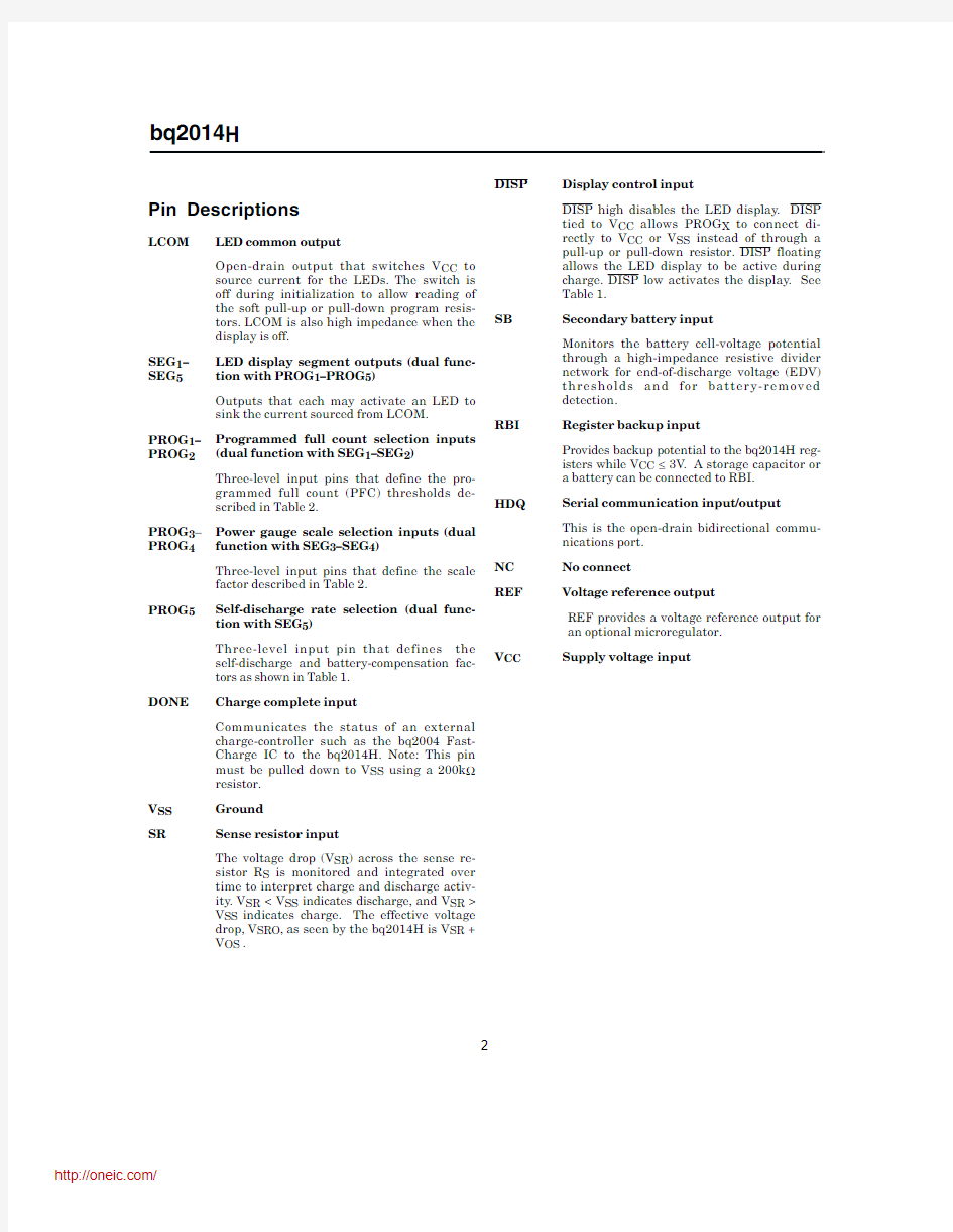
LCOM
LED common output
SEG 1/PROG 1LED segment 1/
program 1input SEG 2/PROG 2LED segment 2/
program 2input SEG 3/PROG 3LED segment 3/
program 3input SEG 4/PROG 4LED segment 4/
program 4input SEG 5/PROG 5LED segment 5/
program 5input DONE
Charge complete input
1PN20140H..eps
16-Pin Narrow SOIC
234 5678
161514131211109
LCOM
SEG 1/PROG 1SEG 2/PROG 2SEG 3/PROG 3SEG 4/PROG 4SEG 5/PROG 5
DONE V SS
V CC REF NC HDQ RBI SB DISP SR
V SS System ground SR Sense resistor input DISP Display control input SB Battery sense input RBI Register backup input HDQ Serial communications input/output NC No connect
REF V oltage reference output V CC
Supply voltage
Pin Connections SLUS030A –JUNE 1999 - REVISED OCTOBER 2003
Low-Cost NiCd/NiMH Gas Gauge IC
Pin Names
Pin Descriptions
LCOM LED common output
Open-drain output that switches V CC to
source current for the LEDs.The switch is
off during initialization to allow reading of
the soft pull-up or pull-down program resis-
tors.LCOM is also high impedance when the
display is off.
SEG1–SEG5LED display segment outputs(dual func-tion with PROG1–PROG5)
Outputs that each may activate an LED to sink the current sourced from LCOM.
PROG1–PROG2Programmed full count selection inputs (dual function with SEG1–SEG2)
Three-level input pins that define the pro-grammed full count(PFC)thresholds de-scribed in Table2.
PROG3–PROG4Power gauge scale selection inputs(dual function with SEG3–SEG4)
Three-level input pins that define the scale factor described in Table2.
PROG5Self-discharge rate selection(dual func-tion with SEG5)
Three-level input pin that defines the
self-discharge and battery-compensation fac-
tors as shown in Table1.
DONE Charge complete input
Communicates the status of an external
charge-controller such as the bq2004Fast-
Charge IC to the bq2014H.Note:This pin
must be pulled down to V SS using a200k?
resistor.
V SS Ground
SR Sense resistor input
The voltage drop(V SR)across the sense re-
sistor R S is monitored and integrated over
time to interpret charge and discharge activ-
ity.V SR
V SS indicates charge.The effective voltage
drop,V SRO,as seen by the bq2014H is V SR+
V OS.
DISP Display control input
DISP high disables the LED display.DISP
tied to V CC allows PROG X to connect di-
rectly to V CC or V SS instead of through a
pull-up or pull-down resistor.DISP floating
allows the LED display to be active during
charge.DISP low activates the display.See
Table1.
SB Secondary battery input
Monitors the battery cell-voltage potential
through a high-impedance resistive divider
network for end-of-discharge voltage(EDV)
thresholds and for battery-removed
detection.
RBI Register backup input
Provides backup potential to the bq2014H reg-
isters while V CC≤3V.A storage capacitor or
a battery can be connected to RBI.
HDQ Serial communication input/output
This is the open-drain bidirectional commu-
nications port.
NC No connect
REF Voltage reference output
REF provides a voltage reference output for
an optional microregulator.
V CC Supply voltage input
2
bq2014H
Functional Description
General Operation
The bq2014H determines battery capacity by moni-toring the amount of current input to or removed from a rechargeable battery.The bq2014H mea-sures discharge and charge currents,measures bat-tery voltage,estimates self-discharge,monitors the battery for low battery-voltage thresholds,and com-pensates for temperature and charge/discharge rate. Current measurement is made by monitoring the voltage across a small-value series sense resistor be-tween the negative battery terminal and ground. The bq2014H compensates the nominal available capacity register for discharge rate and tempera-t u r e a n d r e p o r t s t h e c o m p e n s a t e d a v a i l a b l e capacity.The bq2014H uses the compensated available
capacity to drive the LED display.In addition,the bq2014H estimates the available energy using the aver-age battery voltage during the discharge cycle and re-maining compensated available capacity.
Figure1shows a typical battery pack application of the bq2014H using the LED display capability as a charge-state indicator.The bq2014H is configured to display capacity in relative display mode.The relative display mode uses the last measured discharge capacity of the battery as the battery“full”reference.A push-button display feature is available for momentarily enabling the LED display.
The bq2014H monitors the charge and discharge cur-rents as a voltage across a sense resistor.(See R S in Fig-ure1.)A filter between the negative battery terminal and the SR pin is required.
3
Figure 1.Battery Pack Application Diagram—LED Display
bq2014H
Voltage Thresholds
In conjunction with monitoring V SR for charge/discharge currents,the bq2014H monitors the battery potential through the SB pin for the end-of-discharge voltage(EDV) thresholds.
The EDV threshold levels are used to determine when the battery has reached an“empty”state.
The EDV thresholds for the bq2014H are programmable with the default values fixed as follows:
EDV1 (first) = 0.76V
EDVF(final) = EDV1 - 0.025V = 0.735V
The battery voltage divider(RB1and RB2in Figure1)is used to scale these values to the desired threshold.
If V SB is below either of the two EDV thresholds,the as-sociated flag is latched and remains latched,independ-ent of V SB,until the next valid charge.
EDV monitoring is disabled if the
is
greater than2C(OVLD Flag=1)and resumes second after the rate falls below2C.The V SB value is
over the serial port.
RBI Input
The RBI input pin is used with a storage capacitor or ex-ternal supply to provide backup potential to the internal bq2014H registers when V CC drops below3.0V.V CC is output on RBI when V CC is above3.0V.If using an exter-
nal supply(such as the bottom series cell)as the backup source,an external diode is required for isolation.
Reset
The bq2014H can be reset by removing V CC and ground-ing the RBI pin for15seconds or by commands over the serial port.The serial port reset command sequence re-quires writing00h to register PPFC(address=1Eh)and then writing00h to register LMD(address=05h). Temperature
The bq2014H internally determines the temperature in 10°C steps centered from approximately-35°C to+85°C. The temperature steps are used to adapt charge and dis-charge rate compensations,self-discharge counting,and available charge display translation.
The temperature range is available over the serial port in10°C increments,as shown in the following table
Layout Considerations
The bq2014H measures the voltage differential between the SR and V SS pins.V OS(the offset voltage at the SR pin)is greatly affected by PC board layout.For optimal results,the PC board layout should follow the strict rule of a single-point ground return.Sharing high-current ground with small-signal ground causes undesirable noise on the small-signal nodes.Additionally:
I The capacitors(C1and C2)should be placed as
close as possible to the V CC and SB pins, respectively,and their paths to V SS should be as short as possible.A high-quality ceramic capacitor of0.1μF is recommended for V CC.
I The sense-resistor capacitor should be placed as close
as possible to the SR pin.
I The sense resistor(R S)should be as close as possible to
the bq2014H.
4
TMP(hex)Temperature Range
0x< -30°C
1x-30°C to -20°C
2x-20°C to -10°C
3x-10°C to 0°C
4x0°C to 10°C
5x10°C to 20°C
6x20°C to 30°C
7x30°C to 40°C
8x40°C to 50°C
9x50°C to 60°C
Ax60°C to 70°C
Bx70°C to 80°C
Cx> 80°C
bq2014H
Gas Gauge Operation
The operational overview diagram in Figure2illustrates the operation of the bq2014H.The bq2014H accumu-lates a measure of charge and discharge currents,as well as an estimation of self-discharge.The accumu-lated charge and discharge currents are adjusted for temperature and rate to provide the indication of com-pensated available capacity to the host system or user. The main counter,Nominal Available Capacity(NAC), represents the available battery capacity at any given time.Battery charging increments the NAC register, while battery discharging and self-discharge decrement the NAC register and increment the DCR(Discharge Count Register).
The Discharge Count Register is used to update the Last Measured Discharge(LMD)register only if a complete battery discharge from full to empty occurs without any partial battery charges.Therefore,the bq2014H adapts its capacity determination based on the actual condi-tions of discharge.
The battery's initial capacity equals the Programmed Full Count(PFC)shown in Table2.Until LMD is up-dated,NAC counts up to but not beyond this threshold during subsequent charges.This approach allows the gas gauge to be charger-independent and compatible with any type of charge regime.
https://www.doczj.com/doc/0c17106793.html,st Measured Discharge(LMD)or learned
battery capacity:
LMD is the last measured discharge capacity of the
battery.On initialization(application of V CC or bat-
tery replacement),LMD=PFC.During subsequent
discharges,the LMD is updated with the latest
measured capacity in the Discharge Count Register
representing a discharge from full to below EDV1.
A qualified discharge is necessary for a capacity
transfer from the DCR to the LMD register.The
LMD also serves as the100%reference threshold
used by the relative display mode.
5
Figure 2.Operational Overview
bq2014H
2.
Programmed Full Count (PFC)or initial bat-tery capacity:
The initial LMD and gas gauge rate values are pro-grammed by using PROG 1–PROG 4.The bq2014H is configured for a given application by selecting a PFC value from Table 2.The correct PFC may be determined by multiplying the rated battery capac-ity in mAh by the sense resistor value:Battery capacity (mAh)*sense resistor (?) =
PFC (mVh)
Selecting a PFC slightly less than the rated capac-ity provides a conservative capacity reference until the bq2014H “learns”a new capacity reference.
Example:Selecting a PFC Value Given:
Sense resistor =0.05?Number of cells =10
Capacity =3500mAh,NiMH Current range =50mA to 1A Relative display mode
Self-discharge
=per day @25°C
Voltage drop over resistor =2.5mV to 50mV Nominal discharge voltage =1.2V Therefore:
3500mAh *0.05?= 175mVh
6
PROG x Pro-grammed Full Count (PFC)
PROG 4= L
PROG 4= Z or H
Units 12PROG 3= H PROG 3= Z PROG 3= L PROG 3= H PROG 3= Z PROG 3
= L ---SCALE =1/80SCALE =1/160SCALE =1/320SCALE =1/640SCALE =1/1280SCALE =1/2560mVh/count H H 4915261430715476.838.419.2mVh H Z 4505656328214170.435.217.6mVh H L 4096051225612864.032.016.0mVh Z H 3686446123011557.628.814.4mVh Z Z 3379242221110653.026.413.2mVh Z L 3072038419296.048.024.012.0mVh L H 2764834617386.443.221.610.8mVh L Z 2560032016080.040.020.010.0mVh L
L
22528
28214170.435.217.68.8mVh V SR equivalent to 2counts/s (nom.)
90
45
22.5
11.25
5.6
2.8
mV
Table 2.bq2014H Programmed Full Count mVh,V SR Gain Selections
Table 1.Self-Discharge and Capacity Compensation
bq2014H
Select:
PFC=27648counts or173mVh
PROG1=low
PROG2=high
PROG3=float
PROG4=low
PROG5=low
The initial full battery capacity is173mVh (3460mAh)until the bq2014H“learns”a new capac-ity with a qualified discharge from full to EDV1.
3.Nominal Available Capacity(NAC):
NAC counts up during charge to a maximum value of LMD and down during discharge and self-dis-charge to0.NAC is reset to0on initialization and on the first valid charge following discharge to EDV1.To prevent overstatement of charge during periods of overcharge,NAC stops incrementing when NAC=LMD or0.94?LMD if T<0°C.
4.Discharge Count Register(DCR):
The DCR counts up during discharge independent of NAC and could continue increasing after NAC has decremented to0.Prior to NAC=0(empty battery),both discharge and self-discharge in-crement the DCR.After NAC=0,only discharge increments the DCR.The DCR resets to0when NAC≥0.94?LMD and a discharge is detected.The DCR does not roll over but stops counting when it reaches FFh.
The DCR value becomes the new LMD value on the first charge after a valid discharge to V EDV1if all the following conditions are met:
I No valid charge initiations(charges greater than
2NAC updates where V SRO>V SRQ)occurred
during the period between NAC≥0.94?LMD and
EDV1.
I The self-discharge is less than6.25%of NAC.
I The temperature is≥0°C when the EDV1level
is reached during discharge.
I The discharge begins when NAC≥0.94?LMD.
I VDQ is set.
The valid discharge flag(VDQ)indicates whether the present discharge is valid for LMD update.If the DCR update value is less than0.94?LMD, LMD will only be modified by0.94?LMD.This pre-vents invalid DCR values from corrupting LMD.
5.Scaled Available Energy(SAE):
SAE is useful in determining the available energy within the battery,and may provide a more useful
capacity reference in battery chemistries with
sloped voltage profiles during discharge.SAE may
be converted to an mWh value using the following
formula:
E(mWh) =(SAEH SAEL)
?+?
256
12.??
?
SCALE(R+R)
R R
B1B2
S B2
where R B1,R B2,and R S are resistor values in
ohms,as shown in Figure1.SCALE is the selected
scale from Table2.
https://www.doczj.com/doc/0c17106793.html,pensated Available Capacity(CACT)
CACT counts similarly to NAC,but contains the
available capacity compensated for discharge rate
and temperature.
Charge Counting
Charge activity is detected based on a positive voltage on the SR input.If charge activity is detected,the bq2014H increments NAC at a rate proportional to V SR and,if enabled,activates the LED display.
The bq2014H counts charge activity when the voltage at the SR input(V SRO)exceeds the minimum charge threshold(V SRQ).A valid charge is detected when NAC has been updated twice without discharging or reaching the digital magnitude filter time-out.Once a valid charge is detected,charge counting continues until V SR, including offset,falls below V SRQ.
Discharge Counting
Discharge activity is indicated by a negative voltage on the SR input.All discharge counts where V SRO is less than the minimum discharge threshold(V SRD)cause the NAC register to decrement and the DCR to increment.
Self-Discharge Counting
The bq2014H continuously decrements NAC and incre-ments DCR for self-discharge on the basis of time and tem-perature.
Charge/Discharge Current
The bq2014H current-scale registers,VSRH and VSRL, can be used to determine the battery charge or dis-charge current.See the Current Scale Register descrip-tion for details.
7
bq2014H
Count Compensations
Charge Compensation
Two charge efficiency compensation factors are used for trickle and fast charge.Trickle charge is defined as a rate of charge Charge Temperature Trickle-Charge Compensation Fast-Charge Compensation < 40°C0.810.94 > 40°C0.750.88 Compensated Available Capacity NAC is adjusted for rate of discharge and temperature to derive the CACD and CACT values. Corrections for the rate of discharge are made by adjust-ing an internal discharge compensation factor.The dis-charge factor is based on the discharge rate.This com-pensation is applied to NAC to derive the value in the CACD register. The compensation factors during discharge are: Approximate Discharge Rate Rate Efficiency Factor < 2C100% > 2C95% Temperature compensation during discharge also takes place.At lower temperatures,the compensation factor increases by0.05for each10°C temperature range below 10°C.This compensation is applied to CACD to derive the value in the CACT register.The temperature com-pensation factor follows the equation Temperature Efficiency Factor = 1.00 - (0.05?N) where N=number of10°C steps below10°C. For example, T>10°C:Nominal compensation,N=0 0°C -10°C -20°C -20°C (temperature efficiency=80%) Self-Discharge Compensation The compensation is programmed for a nominal rate of*NAC per day,?NAC per day,or disabled.the rate for within the 20°C–30°C temperature range(TMPGG=6x).This rate varies across8ranges from<10°C to>70°C,doubling with each higher temperature step(10°C).See Table3. Digital Magnitude Filter The bq2014H has a digital filter to eliminate charge and discharge counting below a set threshold.The threshold for both V SRD and V SRQ is250μV. 8 Table 3.Self-Discharge Compensation bq2014H Error Summary Capacity Inaccurate The LMD is susceptible to error on initialization or if no updates occur.On initialization,the LMD value in-cludes the error between the programmed full capacity and the actual capacity .This error is present until a valid discharge occurs and LMD is updated.(See the DCR description.)The other cause of LMD error is bat-tery wear-out.As the battery ages,the measured capac-ity must be adjusted to account for changes in actual battery capacity . A Capacity Inaccurate counter (CPI)is maintained and incremented each time a valid charge occurs (qualified by NAC;see the CPI register description).It is reset whenever LMD is updated from the DCR.The counter does not wrap around but stops counting at 255.The ca-pacity inaccurate flag (CI)is set if LMD has not been up-dated following 64valid charges. Current-Sensing Error Table 6shows the non-linearity and non-repeatability errors associated with the bq2014H current sensing.Table 7illustrates the current-sensing error as a func-tion of V OS .A digital filter prevents charge and dis-charge counts to the NAC register when V SRO is be-tween V SRQ and V SRD . Done Input A charge-control IC or a microcontroller uses the DONE input to communicate charge status to the bq2014H.When the DONE input is asserted high on charge com-pletion,the bq2014H sets NAC =LMD and VDQ =1.The DONE input should be maintained high as long as the charge controller or microcontroller keeps the bat-teries full;otherwise,the pin should be held low . Communicating with the bq2014H The bq2014H includes a simple single-pin (HDQ plus re-turn)serial data interface.A host processor uses the in-terface to access various bq2014H registers.Battery characteristics may be easily monitored by adding a sin-gle contact to the battery pack.The open-drain HDQ pin on the bq2014H should be pulled up by the host sys-tem,or may be left floating if the serial interface is not used. The interface uses a command-based protocol,in which the host processor sends a command byte to the bq2014H.The command directs the bq2014H to either store the next eight bits of data received to a register specified by the command byte or output the eight bits of data specified by the command byte.(See Figure 4.)The communication protocol is asynchronous https://www.doczj.com/doc/0c17106793.html,mand and data bytes consist of a stream of eight bits that have a maximum transmission rate of 5K bits/sec.The least-significant bit of a command or data byte is transmitted first.The protocol is simple enough that it can be implemented by most host proces-sors using either polled or interrupt processing.Data input from the bq2014H may be sampled using the pulse-width capture timers available on some microcon-trollers. If a communication error occurs (e.g.,t CYCB >250μs),the bq2014H should be sent a BREAK to reinitiate the serial interface.A BREAK is detected when the HDQ pin is driven to a logic-low state for a time,t B or greater.The HDQ pin should then be returned to its normal ready-high logic state for a time,t BR .The bq2014H is now ready to receive a command from the host proces-sor. 9 V OS (μV)Sense Resistor 2050100m ? 500.250.100.05%1000.500.200.10%1500.750.300.15%180 0.90 0.360.18 % Table 7.V OS -Related Current Sense Error (Current = 1A) Symbol Parameter Typical Maximum Units Notes INL Integrated non-linearity error ±2±4%Add 0.1% per °C above or below 25°C and 1% per volt above or below 4.25V .INR Integrated non-repeatability error ±1 ±2 % Measurement repeatability given similar operating conditions. Table 6.bq2014H Current-Sensing Errors bq2014H The return-to-one data bit frame consists of three dis-tinct sections: 1.The first section is used to start the transmission by either the host or the bq2014H taking the HDQ pin to a logic-low state for a period,t STRH;B. 2.The next section is the actual data transmission, where the data should be valid by a period,t DSU;B, after the negative edge used to start communica-tion.The data should be held for a period,t DH;DV, to allow the host or bq2014H to sample the data bit. 3.The final section is used to stop the transmission by returning the HDQ pin to a logic-high state by at least a period,t SSU;B,after the negative edge used to start communication.The final logic-high state should be until a period t CYCH;B,to allow time to en-sure that the bit transmission was stopped prop-erly.The timings for data and break communication are given in the serial communication timing speci-fication and illustration sections. Communication with the bq2014H is always performed with the bit transmitted first.Figure5shows an example of a communication sequence to read the bq2014H NACH register. bq2014H Command Code and Registers The bq2014H status registers are listed in Table8and de-scribed below.All registers are Read/Write in the bq2014H. Caution:When writing to bq2014H registers ensure that proper data are written.A write-verify read is recommended. Command Code The bq2014H latches the command code when eight valid command bits have been received by the bq2014H. The command code contains two fields: I W/R bit I Command address The W/R bit of the command code is used to select whether the received command is for a read or a write function: The W/R values are Command Code Bits 76543210 W/R-------where W/R is 0The bq2014H outputs the requested regis- ter contents specified by the address por- tion of command code. 1The following eight bits should be written to the register specified by the address por- tion of command code. The lower7-bit field of the command code contains the address portion of the register to be accessed: Command Code Bits 76543210 -AD6AD5AD4AD3AD2AD1 AD0 (LSB) Primary Status Flags Register(FLGS1) The FLGS1register(address=01h)contains the pri-mary bq2014H flags. The charge status flag(CHGS)is asserted when a valid charge rate is detected.Charge rate is deemed valid when V SRO>V SRQ.A V SRO of less than V SRQ or discharge activity clears CHGS. The CHGS values are FLGS1 Bits 76543210 CHGS-------where CHGS is 0Either discharge activity detected or V SRO ≤V SRQ 1V SRO>V SRQ The battery replaced flag(BRP)is asserted whenever the bq2014H is reset either by application of V CC or by a serial port command.BRP is reset when either a valid charge action increments NAC to be equal to LMD,or a valid charge action is detected after the EDV1flag is as-serted.BRP=1signifies that the device has been reset. The BRP values are FLGS1 Bits 76543210 -BRP------where BRP is 0Battery is charged until NAC=LMD or dis-charged until the EDV1 flag is asserted 1bq2014H is reset 4-10 bq2014H 分销商库存信息: TI BQ2014HSN BQ2014HSNTR BQ2014HSNTRG4 BQ2014HSNG4BQ2014HEVM-001
相关主题
文本预览