page 1 From AOP to UML Towards an Aspect-Oriented Architectural Modeling Approach
- 格式:pdf
- 大小:173.17 KB
- 文档页数:15
软件工程非选择题1.Capability Maturity Model Integration (CMMI)能力成熟度模型集成,是一个过程元模型,定义了如何建立完整的软件过程,软件组织所应该具备的过程特征。
分为不完全级、已执行级、已管理级、已定义级、已定量管理级、优化级。
e-Cases指从系统外部可见的系统的一个功能,也就是描述系统应该完成什么功能。
rmation Hiding信息隐藏:这是把系统分解为模块时的思想,即模块内部的数据与过程,应该对不需要了解这些数据与过程的模块隐藏起来。
只有为了完成软件的总体功能而必须在模块间交换的信息,才允许在模块间进行传递。
4.Waterfall model是一种基于软件生存周期的线性开发模型。
它提出了一个系统的、顺序的软件开发方法,从用户需求规格说明开始,通过策划、建模、构件和部署的过程,最终提供一个完整的软件并提供持续的技术支持。
5.Incemental model增量模型:以迭代的方式运用瀑布模型。
这种模型把软件看作是一系列相互联系的增量,在开发过程的各次迭代中,每次完成其中的一个增量。
6.Software engineering(17)软件工程是:(1)将系统化的,规范化,可量化的方法应用于软的开发,运行和维护,即将工程化的方法应用于软件。
(2)在(1)中所述方法的研究7.Unified Modeling Language (UML)统一建模语言,对软件进行可视化、规约、构造、文档化的一种语言。
8.prototyping model原型模型的思想是:先建立一个能够放映用户主要需求的原型,让用户实际看一下未来系统的面貌,以便判断哪些功能是符合需要的,哪些方面还需要改进,然后将原型反复改进,直至建立完全符合用户要求的新系统。
9.Software Architecture (200)软件体系结构:一个程序和计算系统软件体系结构是指系统的一个或者多个结构。
结构中包括软件的构件,构件外部可见属性以及他们之间的相互关系。
uml课后习题答案第一章系统建模与分析设计的演变课后习题:1、A2、C3、D4、B5、软件按照其工作方式可划分为实时处理软件、分时处理软件、交互式软件和批处理软件。
6、软件生存周期由软件的定义、软件的开发和软件的使用维护和更新换代三部分组成。
7、软件开发模型有瀑布模型、增量模型、螺旋模型、智能模型和快速原型模型等五种主要模型8、面向对象技术采用以类为中心的封装、继承、多态等不仅支持软件复用,而且使软件维护工作可靠有效,可实现软件系统的柔性制造。
9、UML的优点是:唯一性、连续性、维护性、复用性和完善性。
第二章统一建模语言UML1、A2、B3、C4、D5、B6、UML分析和设计模型由三类模型图表示,三类模型图是:用例模型图、静态模型图和动态模型图。
7、UML的软件统一开发过程,即生命周期按时间顺序可以划分为,开始,详细设计,系统构造和移交四个阶段及阶段中一系列的循环重复。
8、UML开发过程是一种二维结构软件开发过程,软件项目开发过程流程包括的核心工作内容是,分析,设计,实现,测试和配置9、UML中的五个不同的视图可以完整地描述出所建造的系统,这五种视图是用例视图、逻辑视图、构件视图、进程视图和配置视图。
10、UML中有10中基本图可以完整地描述出所有建造的系统,这10中视图是用例图、类图、对象图、包图、构件图、配置图、序列图、活动图、状态图和合作图。
第三章需求分析与用例建模习题:1、B2、A3、C4、D5、B6、A7、A8、UML软件开发过程需求分析阶段产生的模型由三类模型图表示。
他们是:用例模型图、静态模型图和动态模型图。
9、CRC卡中的描述由类名、类特征、类类型、责任和协作者共五部分组成10、软件项目的目的的可行性研究分析中,技术可行性研究包括风险分析、资源分析、技术分析三部分组成11、在UML软件开发过程的需求分析阶段,建立用例模型的步骤分为,确定系统的范围和边界,确定系统的执行者和用例,对用例进行描述,定义用例之间的关系和审核用例模型。

实验报告面向对象分析设计1. 引言面向对象分析与设计(Object-Oriented Analysis and Design,简称OOAD)是一种软件开发方法论,它以对象为中心,将软件系统看作是一组互相协作的对象集合。
本实验旨在通过一个具体的案例,通过分析和设计实践,掌握面向对象分析与设计的基本原则和方法。
2. 实验目的通过本实验,我们将学习和掌握以下内容:- 了解面向对象分析与设计的概念和基本原则- 学习使用UML(Unified Modeling Language)进行面向对象分析和设计- 掌握面向对象分析与设计的基本流程和方法- 熟悉常用的面向对象分析与设计工具和技术3. 实验内容及步骤3.1 实验环境本实验使用以下工具和环境:- UML工具:如Visual Paradigm、StarUML等- 编辑器:如Visual Studio Code、Eclipse等- 编程语言:Java、C++等3.2 实验步骤本实验主要分为以下几个步骤:1. 了解案例需求:首先,我们需要明确一个具体的案例,如图书馆管理系统、学生选课系统等。
本实验以图书馆管理系统为例。
2. 创建用例图:使用UML工具,根据需求,创建图书馆管理系统的用例图。
用例图描述系统的功能需求,包括用户角色、用户的需求和系统的功能。
3. 创建类图:基于用例图和需求分析,使用UML工具创建类图。
类图描述系统的静态结构,包括类和类之间的关系。
4. 创建时序图:基于用例图和类图,使用UML工具创建时序图。
时序图描述系统的动态行为,展示对象之间的交互关系和顺序。
5. 完善设计:基于用例图、类图和时序图,进一步完善系统设计。
包括类的属性和方法的设计、系统的架构设计等。
4. 实验结果与分析通过本实验,我们完成了图书馆管理系统的面向对象分析与设计。
通过用例图、类图和时序图的创建,我们清晰地描述了系统的功能需求、静态结构和动态行为。
通过系统设计的完善,我们定义了系统的架构和各个类的属性和方法。
1.What is object technology? What do you perceive as object technology’s strength? It’s weakness?Object【A set of principles (abstraction, encapsulation, polymorphism) guiding software construction, together with languages, databases, and other tools that support those principles.】面向对象技术是一系列支持软件开发的原则(抽象,封装,多态性),以及支持这些原则的程序设计语言,数据库和其它工具。
【Reflects a single paradigm.Facilitates architectural and code reuse.Reflects real world models more closely.Encourages stability.Is adaptive to change】反映一个特定实例。
有利于构件和代码重用。
更加真实地反映现实世界模型。
具有更好的稳定性。
能适应需求的变化。
2.What is UML? List at least three benefits of developing with UML.【UML is Unified Modeling Language, it is a language for Visualizing, Specifying, Constructing, Documenting the artifacts of a software-intensive system. 】UML是统一建模语言,是一门用于对面向对象开发的产品进行可视化建模,说明,架构和文档编制的标准语言。
一、选择题,每题1分,共计20分。
每个括号里的数字为该空的题号,从该题号对应的备选答案中选择最佳的一项,每空限填一个选项。
请按如下表格在答题纸上答此题。
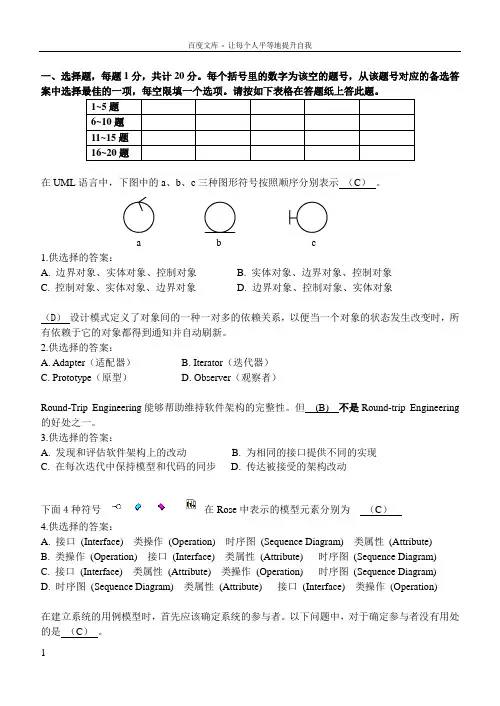
1~5题6~10题11~15题16~20题在UML语言中,下图中的a、b、c三种图形符号按照顺序分别表示(C)。
a b c1.供选择的答案:A. 边界对象、实体对象、控制对象B. 实体对象、边界对象、控制对象C. 控制对象、实体对象、边界对象D. 边界对象、控制对象、实体对象(D)设计模式定义了对象间的一种一对多的依赖关系,以便当一个对象的状态发生改变时,所有依赖于它的对象都得到通知并自动刷新。
2.供选择的答案:A. Adapter(适配器)B. Iterator(迭代器)C. Prototype(原型)D. Observer(观察者)Round-Trip Engineering能够帮助维持软件架构的完整性。
但(B) 不是Round-trip Engineering 的好处之一。
3.供选择的答案:A. 发现和评估软件架构上的改动B. 为相同的接口提供不同的实现C. 在每次迭代中保持模型和代码的同步D. 传达被接受的架构改动下面4种符号在Rose中表示的模型元素分别为(C)4.供选择的答案:A. 接口(Interface) 类操作(Operation) 时序图(Sequence Diagram) 类属性(Attribute)B. 类操作(Operation) 接口(Interface) 类属性(Attribute) 时序图(Sequence Diagram)C. 接口(Interface) 类属性(Attribute) 类操作(Operation) 时序图(Sequence Diagram)D. 时序图(Sequence Diagram) 类属性(Attribute) 接口(Interface) 类操作(Operation)在建立系统的用例模型时,首先应该确定系统的参与者。
1.What is object technology? What do you perceive as object technology’s strength? It’s weakness?OOT is such a technology that facing the objective world and the question realm and using the generally thinking way of human-beings to acknowledge the nature world to describe some things.OOT fit the thinking way of human-beings and easy to protect and functions’ addition and decrease are also become more convenient. And OOT’s reusing is more strengthen.weakness2. What is UML? List at least three benefits of developing with UML.UML(Unified Modeling Language)is used to proceeding the visual model of software dense system.(1)UML can help to express things exactly.(2)UML can help programmer to write a better code.(3)UML can accelerate the procedure’s development.3.What process characteristic best fit the UML? Describe each characteristic.4.What is a use-case driven process? What is use-case? What are the benefits of use case?It is the use-case become a guidance of program.Use-case is a description of system functions.Use-case can help us to get a general impression of the determined system.5.What is system’s architecture? What is an architecture-centric Process?System’s architecture is an overall construction of a system, it include the concept, the requirements and all of the detail in implementing the project. The architecture-centric process is a process that exploit a software use the system’s architecture.6.What is iteration? What are the benefits of Iterative Development?Iteration is a way of exploiting the software that finishing the software in several steps, and it need the customer present his advices after every step in order to ensure the product can fit to the requirements of the customer’s. Iteration can ensure a lower risk in a large project.7.What are the basic principles of OO technology? Describe each in detail.Abstraction, it report those important properties connect to the applications.Encapsulation, it can cover details of implementation and is the basis of the modularity.Modularity, it break complex part into simple piecesHierarchy, it provides a method that can let the son class to get data from father class.8.What is use case model? Which artifacts can be included in a use case model?9.List three types of relationships existed between different use cases and give examples.Generalization, Include, Extend.Generalization, apples and bananas can be generalized as fruit.Include, the banana peel is included in the banana.Extend, we can eat the banana, but we can also smash it and mixed it with yogurt and drink it, drinking is an extension.10.Explain the following diagram and their elements with examples.1) Use case diagram 2) Activity diagram 3) Sequence diagram 4) Collaboration diagram5) Class diagram 6) state chart diagram 7) Deployment diagram1)2)3)4)5)6)7)11.Describe the similarities and differences between the sequence diagram and collaborationdiagram.They are both interactive diagram, but collaboration diagram don’t care about when the information be transferred.12.Define the different relationships in class diagram: dependency, association, aggregation,composition, generalization.Dependency, is a connection during two classes, one class depend another class.Association, it let a class acquire another class’s functions and attributes.Aggregation, it is the association but those two classes are in different levels, one is entity but the other one is part.Composition, it is a kind of aggregation, it demands the object that represent the entity in responsible of the life cycle of the object that represent the part.Generalization, it represents the hierarchy between two classes.13.What is a node in deployment diagram? List two different types of nodes.Node in deployment diagram always represent a device .14.Describe the extensibility mechanisms of UML.15.What is the function of Stereotypes?Give two examples of stereotypes.16.Explain the six best practices of software engineering.1)Iteration 2)Manage requirements 3)Module-basis architecture 4)visualization modeling5) software quality’s confirmation 6)Control the changes of software.17.What is RUP? How many phases are there in RUP? Describe each phase’s purpose andmilestone.It is a programming exploitation methodology which is OOT and web-basis.Inception, Elaboration, Construction, TransitionInception: Constructing the business cases of system and confirm the edge of the project.Lifecycle objective.Elaboration: Analysis the problem domain.Lifecycle architecture.Construction: Product’s exploitation.Initial operation.Transition: Ensuring the software is usable to the customer.Product release. and briefly describe the “4+1”views of architecture.Ans:Which of the four views are:Logical View which is the logical relationship around the objects,Process View which is the view that show the actions of the objects or software actions,Deployment View which is to show the relatonship between the module of the objects and Implementation View which is the software implementations.And the one view can be Use-Case View.19.What is the difference between analysis and design?The analysis focus on understanding of de problem,but the design focus on the understanding of the solution.20.Please describe the whole process of OO analysis and design with UML.Ans:1.Build the requirement model-the plan for the reqiurement2.Build the basic model-Class diagram3.Build the assistant diagram4.Design the protocol of the model5.Prototype Development21.What is a layered architecture? Give examples of typical layers.Ans:A layered architecture can be descript as the “separation of responsibility which is to say that each layer is responsible for a finite amount of work.For instance,a company may has its enterprise architecture.The layers of the manager and the layers of the employees.They have the responsibilities themselves and they have their own layers.22.What are analysis mechanisms? What are design mechanisms? Give examples.Ans:Analysis mechanisms can be a process which may run through the whole analysis.And so does the design mechanisms.For instance,a analysis mechanisms may contains Auditing, Communication and so on.23.What is an analysis class? Name and describe the three analysis stereotypes. Give examples. Boundary Classes: Behavior that involves communication with an actorEntity Classes: Behavior that involves the data encapsulated within the abstractionControl Classes: Behavior specific to a use case or part of a very important flow of events24.What is Use-case realization? What‘s your understandings about the benefit of the use-caserealization structure.Ans:The Use-case realization is a method to realize the problem that we should analyse.The use-case realization structure helps to organize the model elements needed to realize the use cases in the design model.25.Describe the steps occurred in the use-case analysis.Ans:It may contain five steps: (1)Identify Use Cases,(2)Indentify Domain Class and relationships,(3)Define the System Sequence Diagram for each use case,(4)Produce an operation,(5)Draw a sequence diagram for each use case.26.What’s the package, and why we need package?Ans:Package is a universal mechanism that organize other elements of the models together.Why we need?If a system has a lot of structures and we have to know more about the structures,then we should point to the so many elements that the systems or the structureshave.And at that time we can find that this may big a complex and hard work.So the package has been developed for this. Package is a universal mechanism that organize other elements of the models together.So we can analyse the system from the bigger layers instead of the great number of the element.27.What is a subsystem? What is an interface? How does a subsystem differ from a package? Ans: A subsystem is a coherent and somewhat independent component of a larger system.It is an element of the model,and it contains the semantics of the packages and the classes.An interface can be an operation about the subsystem.A subsystem realizes one or more interfaces that define its behavior.28.What is the purpose of describing the run-time architecture? How to model the process view? Ans:Describing the run-time architecture’s purpose is:Analyze concurrency requirements,Identify processes and threads,Identify process lifecycles, Map processes onto the implementation and Distribute model elements amongProcesses.The Process View is an “architecturally significant” slice of theprocesses and threads of the Design Model.Processes can be modeled using:1. Active classes (Class Diagrams) and Objects(Interaction Diagrams)ponents (Component Diagrams)29.What is the purpose of describing the distribution? How to model the deployment view? Ans:The purpose is to Reduce processor load.For the Special processing requirements,Scaling concerns,Economic concerns and Distributed access to the system.The Deployment View is an “architecturally significant” slice of the Deployment Model.The deployment view will contain nodes and connections.Connection lines are used to connect the nodes that will be Physical run-time computational resource,Processor node and Device node.And connections may contain Communication mechanism,Physical medium and Software protocol30.Describe the 3 typical distribution patterns, C/S , B/Sand P2P.Ans:C/S:Client/Server, in network connections pattern, besides coordinated net, but also has another form network, namely client/server net, Client/Server. In the client/server network, the server is the network core, but the client is the network foundation, the client dependence server obtains the network resource which needs, but the server provides the network for the client to resources.B/S: Browser/Server,is called as Browser/Server patterns.It is developing as the development of Internet,it is improved from the C/S.P2P: Peer-to-peer network. According to the network in the shared resource way's difference, the local area network has two kind of configurations of organization: One kind is the peer-to-peer network (), another kind is the workstation/server structure. Between peer-to-peer network's computer may correspond mutually and the shared resource (document, peripheral device and so on); But in the workstation/server structure's network may the shared resource place on special purpose computer - server (server), between workstation not mutually direct shared resource. 31.What is the difference between the process models of agile and RUP?Ans: Rational Unified Process is a whole software process,but the process models of agile may bea process in an Architecture or in part of a software.That is to say the RUP may contain the process models of agile.。
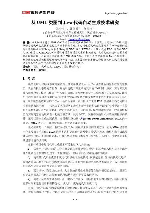
从UML类图到Java代码自动生成技术研究张中宝1,韩同欣2,刘西洋11西安电子科技大学软件工程研究所,陕西西安(710071)2北京航天航空大学计算机学院, 北京(100083)E-mail:zhongbaoz@摘要:本文描述了基于UML CASE平台的代码生成器的设计与实现。
从可执行UML到高级语言的代码生成技术已经在实践中得到实现,本文描述的代码生成器采用了一种全新的面向对象的脚本语言Ruby和基于Ruby的XML接口REXML,处理生成自UML类图的XMI 文档。
通过从XMI DOM树中提取建模系统模型元素的相关信息,之后构造合适的容器类存储提取的数据,并访问这些数据进行ERb模板匹配,最后生成了可执行的Java代码框架。
整个开发过程遵循模型驱动的软件开发方法,以更灵活的脚本语言和模板机制实现了模型驱动架构MDA从平台无关模型到平台相关模型的转化。
关键词:模型,代码生成,MDA(模型驱动架构)中图分类号:TP3121.引言模型是应用程序或系统的某些部分的简单抽象表示。
用户可以以任意的复杂程度构建模型:从在白板上手绘的方框图,到使用建模工具生成的复杂的UML图。
然而,实际开发却经常脱离模型,模型只作为一个系统的蓝图,开发者仍然要手工编写所有的实现代码。
随着应用程序的进展和规模的扩大,开发者经常发现坚持使用模型所带来的约束要远远大于其用途,维护模型变成繁琐的工作而不会产生帮助。
设计阶段产生的UML模型和代码之间的同步变得越来越困难——代码为了应付新增加需求和新产生的想法而不断变化,模型却一直停留在原地不动,这使得模型在一段时间以后失去了它的价值。
模型驱动开发是一种能够将模型与实现更紧密地联系在一起的开发方法。
使用MDD,模型不仅能用来封装应用程序的设计,还可以用来生成实现代码。
它是模型驱动架构[1](Model Driven Architecture, MDA)的一部分,MDA 表示了一种模型驱动开发方法的概念框架。
矿产资源开发利用方案编写内容要求及审查大纲
矿产资源开发利用方案编写内容要求及《矿产资源开发利用方案》审查大纲一、概述
㈠矿区位置、隶属关系和企业性质。
如为改扩建矿山, 应说明矿山现状、
特点及存在的主要问题。
㈡编制依据
(1简述项目前期工作进展情况及与有关方面对项目的意向性协议情况。
(2 列出开发利用方案编制所依据的主要基础性资料的名称。
如经储量管理部门认定的矿区地质勘探报告、选矿试验报告、加工利用试验报告、工程地质初评资料、矿区水文资料和供水资料等。
对改、扩建矿山应有生产实际资料, 如矿山总平面现状图、矿床开拓系统图、采场现状图和主要采选设备清单等。
二、矿产品需求现状和预测
㈠该矿产在国内需求情况和市场供应情况
1、矿产品现状及加工利用趋向。
2、国内近、远期的需求量及主要销向预测。
㈡产品价格分析
1、国内矿产品价格现状。
2、矿产品价格稳定性及变化趋势。
三、矿产资源概况
㈠矿区总体概况
1、矿区总体规划情况。
2、矿区矿产资源概况。
3、该设计与矿区总体开发的关系。
㈡该设计项目的资源概况
1、矿床地质及构造特征。
2、矿床开采技术条件及水文地质条件。
UML软件建模技术技术理论考核试卷四一、单选题(每题2分,共60分)1. 下列UML(建模语言)的陈述,不正确的是( )A.它主要是图形符号,用面向对象的方法描述系统设计B.只用于系统开发的设计阶段C.它可在用户、分析者、设计者和软件开发者之间建立一个舒适的对话D.它是一种语言,用于可视化、具体化、结构化和文档化软件内在系统的不同方面2. 使用()描述Web网页和Java Applet小应用程序之间的依赖关系( )A.类图B.部署图C.状态图D.组件图3. 下列关于类方法的声明,不正确的是( )A.方法定义了类所许可的行动B.从一个类所创建的所有对象可以使用同一组属性和方法C.每个方法应该有一个参数D.如果在同一个类中定义了类似的操作,则他们的行为应该是类似的4. UML中哪种图()用来描述过程或操作的工作步骤( )A、状态图B、活动图C、用例图D、部署图5. 在面向对象的分析与设计中,下面与角色有关的陈述中,正确的是( )A.在每个用例图中操作用例的被称为参与者B.参与者不能是系统时间C.参与者一定是一个人或用户D.使用案例不考虑系统外部的参与者6. 软件生存期包括计划,需求分析和定义(),编码,软件测试和运行维护( )A、软件开发B、软件设计(详细设计)C、软件支持D、软件定义7. 在面向对象的分析与设计中,下列语句正确的有( )A.通过部署图,可以从整体上了解系统节点的拓扑结构B.在部署图中,使用依赖关系符号连接节点C.部署图的节点中不能含有组件D.部署图用于描述系统中软件的构成8. foo类的一个方法调用bar类的一个方法。
除此之外,这两个类之间没有其他关系。
foo类和bar类之间的关系为( )A.关联B.依赖C.继承D.实现E.聚集9. 下列关于用例和用例图的描述,正确的有( )A.系统是用例模型的一个组成部分,它必须代表一个真正的软件系统B.在扩展关系中,扩展后的用例一定要包括所扩展的原用例的全部行为C.用例图中,参与者可以是一个人,一部机器或者一个系统D.用例用一个名字在外面的椭圆表示10. 在面向对象的技术中,()属性可以从类定义的外部来存取,而()属性不可以从类定义的外部来存取。
第一章1.选择题(1)软件工程的概念是在()年被首次提出的。
A.1949B.1968C.1972D.1989(2)下列不属于软件工程的目标的一项是()A.提高软件产品的质量B.提高软件产品的可靠性C.减少软件产品的需求D.控制软件开发成本(3)软件危机产生的主要原因是()A.软件工具落后B.软件生产能力不足C.对软件认识不够D.软件本身的特点及开发方法(4)人们公认的第一门面向对象编程语言是()。
A. SimulaB. SmalltalkC. C++D. Java(5)下列编程语言中不支持面向对象的特性的是()。
A. C++B. ANSI CC. JavaD. Objetive c(6)下列选项中不是面向对象方法的相关原则的是()A.封装B.继承C.多态D.结构(7)()是面向对象方法中用来描述”对客户隐藏对象的属性和实现细节”的概念。
A.封装B.继承C.多态D.抽象(8)下列选项中不属于面向对象方法的优势之-的是()。
A.复用性强B.改善了软件结构C.软件的执行效率更高D.抽象更符合人类的思维习惯2.判断题(1)软件就是程序,编写软件就是编写程序。
对错(2)软件危机的主要表现是软件需求增加,软件价格上升。
对错(3) C语言对面向对象的发展起到了重要作用。
对错(4)面向对象方法中的对象是从客观世界中抽象出来的一个集合体。
对错(5)面向对象可以保证开发过程中的需求变化完全不会导致系统结构的变化。
对错(6)面向对象方法就是使用面向对象的程序设计语言进行编程。
对错(7)对象的自治性指的是对象是完全封闭的,不受任何外界影响。
对错(8)类是面向对象程序中的构造单位,也是面向对象程序设计语言的基本成分。
对错第二章1.选择题1.选择题(1)下列关于模型的表述,不正确的项是()。
A.建模语言只能是图形表示的B.模型所描绘的系统蓝團既可以包括详细的计划,也可以包括系统的总体计划C.模型可以帮助开发组生成有用的工作产品D.最好的模型总是与现实世界联系密切(2) UML的全称是()。
FromAOPtoUML:TowardsanAspect-OrientedArchitecturalModelingApproach
MohamedM.Kandé,JörgKienzleandAlfredStrohmeierSoftwareEngineeringLaboratorySwissFederalInstituteofTechnologyLausanneCH-1015LausanneEPFLSwitzerlandemail:{Mohamed.Kande,Joerg.Kienzle,Alfred.Strohmeier}@epfl.ch
Abstract.Capturingconcernsthatcrosscuttheboundariesofmultiplecompo-nentsinsoftwarearchitecturedescriptionsisproblematic.Standarddescriptionlanguages,suchasUML,donotprovideadequatemeanstounderstandandmodularizesuchconcerns,butaspect-orientedprogrammingtechniquesdo.ThispaperexploresandanalyzesthesuitabilityofUMLforaspect-orientedarchitecturalmodeling.Ittakesabottom-upapproach,startingfromthecodeleveltothelevelofsoftwarearchitecturedescription,viaaspect-orienteddesign,usingstandardUML.
1IntroductionAspect-orientedprogramming(AOP)isthenamegiventoasetoftechniquesbasedontheideathatsoftwareisbetterprogrammedbycapturingdifferent“thingsthathappeninaprogram”indifferentways,andbyencapsulatingthemintodifferentmodules[1].Thisapproachmakesitpossibletoseparatelyspecifyvariouskindsofconcernsandlocalizethemintoseparateunitsofencapsulation.Onecandealwithboththeconcernsandthemodulesthatencapsulatethematdifferentlevelsofabstraction,notonlyatthecode-level[2].Examplesofkindsofconcernsinasoftwaresystemincludefunctional-ity,emergingsystem-levelproperties,andotherqualities.Representingcertainkindsofsoftwareconcernsiswellsupportedbymodelinglanguages,likeUML[3],iftheseconcernscanbelocalizedonasinglecomponentofasystem,suchasaclass.Model-ingotherskindsofconcerns,e.g.,logging,transactionsandsecurity,ismoredifficult,astheytypicallycutacrosstheboundariesofmanycomponentsofasystem.Inthiswork,weconsidertwoissuesthatwebelieveneedtobefundamentallyaddressedwhenprovidingsupportformodelingcrosscuttingconcerns:
•Understandingwhatconcernscutacrosswhichrepresentationalelementsandwheretheydoso.Withoutthisinformation,itbecomesveryhardtorepresentandreasonsimultaneouslyaboutthecrosscuttingstructureandthebehaviorinthesys-tem.•Provideameanstoseparatecrosscuttingfromnon-crosscuttingconcernsandencapsulatetheformerintoaspects.
Totackletheseissues,wetakeabottom-upapproachthatstartswiththekeyconceptsusedtorepresentcrosscuttingconcernsinaspect-orientedprograms.Basedonthisandonourexperienceinmodelingobject-orientedsoftwarewithUML,weanalyzethesuitabilityofUMLtosupportaspect-orientedsoftwaremodeling.Oneofthemainelementsofanaspect-orientedprogramminglanguageisthejoinpointmodel.Itdescribesthe“hooks”whereenhancementsmaybeadded,determiningthusthestructureofcrosscuttingconcerns.Tosupportthismodel,AOPlanguagesarerequiredtoprovidemeanstoidentifyjoinpoints,specifybehavioratjoinpoints,defineunitsthatallowonetogroupjoinpointspecificationsandbehaviorenhance-mentstogether,aswellasmeansforattachingsuchunitstoaprogram[1].AsecondimportantelementinAOPisthe“weaving”capabilitysupport.WhenusingAOPlanguages,theprogrammerreliesontheunderlyingAOPenvironmenttoweaveorcomposeseparateconcernstogetherintoacoherentprogram.Separatingtherepresentationofmultiplekindsofconcernsinprogramsinsuchawaypromisesincreasedreadability,simplerstructure,adaptability,customizabilityandbetterreuse.UMLisastandardmodelinglanguageusedtocreateanddocumentsoftwarearti-facts.Itincludesmanyusefulideasandconceptsthathavetheirrootsinvariousindi-vidualmethodsandtheories.UMLprovidesnumerousmodelingtechniques,includingseveraltypesofdiagrams,modelelements,notationandguidelines.Thesetechniquescanbeusedinvariouswaystomodeldifferentcharacteristicsofasoftwaresystem.KeyfeaturesofUMLcomprise:supportformodelrefinement,extensionmechanisms(stereotypes,taggedvalues,andconstraints),andalanguageforexpressingconstraints(knownastheobjectconstraintlanguage,OCL).UMLhasestablisheditselfasawell-acceptedmodelinglanguagethatprovidesadequatesupportforobject-orientedandcomponent-basedsoftwaredevelopment[4].Basically,therearevariouspossibilitiesofusingUMLtomodelcrosscuttingcon-cernsinasoftwaresystem.Forinstance,joinpointscanberepresentedinUMLasmodelelements,buttheireffectcanalsobeshownindifferentdiagramtypesofUML,e.g.,collaboration,sequenceandstatechartdiagrams.Now,thequestionthatremainstobeaskedishowsuitableisUML,initscurrentstate,formodelingaspect-orientedsoftwaresystems?Toanswerthisquestion,thispapertakesabottom-upapproach,establishingparal-lelsbetweenAOPcodeandUMLmodels.Section2introducesthekeyconceptsofAspectJ,theaspect-orientedprogramminglanguageweusedforourexperiment.Sec-tion3showshowsome,butnotall,AOPconceptscanbemodeledinstandardUML.Section4identifiesextensionstoUMLthatallowustobettercapturetheessenceofaspect-orientedmodeling,andfinally,insection5wedrawsomeconclusionsfromthisexperiment.