外文文献 英文CaCO3吸收二氧化碳
- 格式:pdf
- 大小:320.06 KB
- 文档页数:8
氧化钙和二氧化碳反应生成氢氧化钙,然后氢氧化钙再和二氧化碳反应生成碳酸钙和水,但是没有水,反应是不会进行的。
化学方程式为CaO+CO₂=CaCO₃。
氧化钙为碱性氧化物,对湿敏感。
易从空气中吸收二氧化碳及水分。
与水反应生成氢氧化钙(Ca (OH)2)并产生大量热,有腐蚀性。
二氧化碳与石灰水反应:Ca(OH)2+CO2=CaCO3↓+H2O
二氧化碳的制取原理:CaCO3 + 2HCl =CaCl2+ H2O + CO2↑
注意事项:
氧化钙长时间在空气中暴露会吸收二氧化碳变成粉末状碳酸钙,起不到清塘消毒的作用。
因此生石灰最好现买现用,且选择块状较轻、不含杂质的为好。
若一次用不完剩下的生石灰用塑料袋扎口密封保存。
氧化钙要加入浆后趁热泼洒,忌将残渣倒入池中,以免池鱼误食而死亡,更不可将整块石灰扔到池中进行水体消毒。

二氧化碳论文:二氧化碳碳捕集和封存碳酸盐沉淀钙镁离子【中文摘要】全球气候变化已成为人类目前所面临的最主要的环境问题之一。
CO2的捕集和封存是减缓温室效应,避免出现全球气候灾害的必要措施。
C02排放所引起的气候变化是全球性的、多层次的,因而人类的应对措施也不可能是单一的,必然是百花齐放,任何单一技术或方式都不可能解决全部问题。
本文提出了一种新的碳封存方式——利用形成难溶碳酸盐沉淀的方式来进行CO2封存。
此方法利用海水等富含钙镁离子的媒介,与含有CO2的气流进行传质反应,促使CO2向液相溶解并向CO;-转化,并结合钙镁离子生成难溶的钙镁碳酸盐沉淀,实现CO2在固相中的安全、长久、稳定封存。
首先,对海水脱碳的原理进行了分析。
海水捕集封存C02所依赖的是由气-液-固三相组成的联动的碳酸盐体系,其流程是C02从气相中进入液相,在液相中转化成HCO3-和CO32-,然后液相中的CO32-结合钙镁离子从液相中析出,成为碳酸盐固相。
这一过程的两个主要驱动力是气态CO2的压力和海水溶液的碱度,也就是pH值,对这两个要素在热力学平衡状态时对海水碳酸盐体系各成分的影响进行了分析。
单位体积海水捕集封存CO2的潜力估算表明,以海水为媒介进行碳捕集封存是一种可行的、有潜力的方法,并且浓海水、工业废水、地下卤水以及盐田废水等可以作为海水的替代,有利于因地制宜地应用此工艺,提高了此法的适用性。
其次,在理论分析的基础上,开展了海水脱碳的试验研究,即C02气流与一定碱度的海水在鼓泡床反应器中传质反应。
海水溶液保持一定的碱度是C02碳酸盐化过程顺利进行的必要条件。
在常温常压下,海水脱碳适宜的pH值范围是8-10,弱碱及其共轭盐是良好的提高海水碱度的添加剂,比如氨-氯化铵缓冲溶液。
反应开始后,酸性气体C02的通入使海水溶液开始酸化,pH值持续降低,海水体系中CO32-的含量不断上升,达到沉淀临界浓度时,结合Ca2+和Mg2+从溶液中以碳酸盐沉淀的形式析出。

碱石灰吸收二氧化碳化学方程式1 碱石灰吸收二氧化碳的原理和机制碱石灰是一种常用的化学物质,具有很好的吸收二氧化碳的性质。
在工业领域和生活中,碱石灰常用于污染治理、饮用水处理等方面。
那么,碱石灰是如何吸收二氧化碳的呢?1.1 碱石灰的化学性质碱石灰是氢氧化钙的俗称,化学式为Ca(OH)2。
它是一种碱性物质,具有钙离子和氢氧根离子的特性。
在水中,碱石灰会产生氢氧根离子(OH-)和钙离子(Ca2+),使溶液呈弱碱性。
碱石灰易溶于水,与许多酸类物质反应。
1.2 碱石灰吸收二氧化碳的机理碱石灰可以吸收二氧化碳的原因是它具有一种酸碱反应的特性。
二氧化碳是一种酸性气体,在空气中与水反应生成碳酸(H2CO3)。
碱石灰中的氢氧根离子(OH-)是一种碱性物质,在空气中吸收二氧化碳时会转化成碳酸根离子(CO32-),并释放出水(H2O)。
化学方程式为:Ca(OH)2 + CO2 → CaCO3 + H2O其中,Ca(OH)2为碱石灰,CO2为二氧化碳,CaCO3为碳酸钙。
1.3 碱石灰吸收二氧化碳的应用碱石灰吸收二氧化碳的应用十分广泛。
在工业生产中,碱石灰可以作为一种处理污染的方法,用于净化工厂废气中的二氧化碳。
对于一些工业废水,碱石灰也可以用于钝化污染物。
另外,在环保领域中,碱石灰还可以用于净化家用发电机、汽车尾气中的二氧化碳。
此外,碱石灰也可以作为一种饮用水处理的方式,可用于净化饮用水中的二氧化碳。
2 碱石灰与环境保护碱石灰是环保领域中一种很常见的化学物质,它能够对环境产生积极的影响,保护生态环境。
那么,在环保中碱石灰的具体应用有哪些呢?2.1 碱石灰能够净化大气中的二氧化碳大气中的二氧化碳是一种主要的温室气体,是造成全球气候变化的原因之一。
通过将碱石灰喷洒到大气中,可以减少大气中的二氧化碳浓度,缓解全球气候变化带来的影响。
2.2 碱石灰能够钝化污染物在处理废水和废气时,碱石灰不仅可以吸收二氧化碳,还可以钝化一些有害污染物。
二氧化碳制取氧气化学方程式1.引言1.1 概述概述部分的内容主要是对文章的主题进行简要介绍,说明二氧化碳制取氧气的相关背景和意义。
我们可以编写如下内容:概述:二氧化碳是一种在自然界广泛存在的气体,是地球大气中的重要成分之一。
近年来,随着全球气候变化问题的日益严峻和能源消耗的急剧增加,二氧化碳的排放问题引起了人们的广泛关注。
二氧化碳不仅会导致温室效应和全球变暖,还会对生态环境和人类健康造成严重影响。
然而,同时我们也意识到,二氧化碳在合适的条件下可以发挥一定的价值。
其中之一就是通过二氧化碳的制取来获得氧气。
氧气是我们生活中必不可少的气体,不仅对于人类呼吸和生命活动至关重要,还广泛应用于医疗、工业、冶金等领域。
因此,二氧化碳制取氧气成为了当前一个备受研究和关注的领域。
本文旨在探讨二氧化碳制取氧气的化学方程式,并分析其制取方法和应用前景。
我们将介绍二氧化碳的制取方法和氧气的制取方法,同时详细阐述二氧化碳制取氧气的化学方程式及其反应机理。
通过阐述相关的实验、技术和理论基础,以期为二氧化碳的高效利用和资源化提供一定的参考和借鉴。
希望通过本文的阐述,可以深入了解二氧化碳制取氧气的过程和原理,进一步探讨其在环境保护和能源利用方面的应用潜力。
同时,对于提高能源利用效率、减少二氧化碳排放、保护生态环境具有重要的科学意义和实际价值。
1.2 文章结构本文分为引言、正文和结论三个部分。
将详细介绍二氧化碳制取氧气的化学方程式。
在引言部分,我们将概述本文的主题,即二氧化碳制取氧气的化学方程式,并介绍本文的结构和目的。
通过引言,读者能够了解到本文的研究背景和意义。
在正文部分,我们将分为两个小节。
首先,我们会介绍二氧化碳的制取方法,包括工业生产和实验室制备等方法。
其次,我们将介绍氧气的制取方法,包括常见的分离技术和化学反应法等。
通过对二氧化碳和氧气制取方法的介绍,读者可以了解到二氧化碳制取氧气的基本原理和技术路线。
在结论部分,我们将总结二氧化碳制取氧气的化学方程式,并探讨其应用前景。
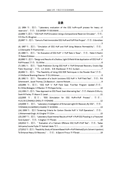
目录(1) 1984年,题目:“Laboratory evaluation of the CO2 huff-n-puff process for heavy oil reservoirs”,作者:S.G.SAYEGH和B.B.MAINI (1)(2)1986年,题目:“CO2 Huff –Puff Simulation Using a Compositional Reservior Simulator”,作者:H.H.Hsu R.J.Brugman (2)(3)1987年,题目:“Camurlu Field Immisicible CO2 Huff and Puff Pilot Project”,作者:S.Gondiken (3)(4) 1987年,题目:“Simulation of CO2 Huff and Puff Using Relative Permeability”,作者:L.C.Denoyelle和P.Lemonnier (4)(5) 1989年,题目:“An Evaluation of CO2 Huff ‘ n’ Puff Tests in Texas”,作者:Helen K.Haskin 和Robert B.Alston (5)(6)1990年,题目:“Design and Results of a Shallow, Light Oilfield-Wide Application of CO2 Huff ‘n’ Puff Process”,作者:ler (6)(7) 1991年,题目:“Scale Prediction During CO2 Huff ‘n’ Puff Enhanced Recovery, Crooks Gap Field, Wyoming”,作者:L.K. Smith,D.B. MacGowan和R.C. Surdam (7)(8)1992年,题目:“The Feasibility of Using CO2 EOR Techniques in the Powder River”,作者:J.K.McDaniel Branting,Chevron和D.L.Whitman (8)(9) 1992年,题目:“Elavuation of a South Louisiana CO2 Huff ‘n’ Puff Field Test”,作者:P.A SchenewerK , Jacob Thomas, Z.A.Bassiouni , Joanne Wolcott (9)(10)1994年,题目:“CO2 Huff ‘n’ Puff Field Case: Five-Year Program Update”,作者:ler,Bretagne, C.P.Bardon和Phillippe Corlay (10)(11) 2001年,题目:“New Approach to CO2 Flood: Soak Alternating Gas”,作者:Malcolm D.Murry, Scott M.Frailey和Akanni S. Lawal (11)(12)2005年,题目:“EOS Stimulation for CO2 Huff-n-Puff Process”,作者:H.LIU,M.C.ZHANG,X.ZHOU,和Y.P.ZHANG (12)(13)2006年,题目:“Laboratory Investigation of Enhanced Light-Oil Recovery By CO2”,作者:Y.P.ZHANG,S.G.SAYEGH,S.HUANG和M.DONG (13)(14) 2006年,题目:“Screening Criteria for Carbon Dioxide Huff ‘n’ Puff Operations”,作者:L.Mohammed-Singh, A.K.Singhal和S.Sim (15)(15) 2007年,题目:“Laboratory Experimental Results of Huff ‘n’Puff CO2 Flooding in a Fractured Core System”,作者:K.Asghari和F.Torabi。

碱石灰吸收二氧化碳化学方程式碱石灰(氢氧化钙)是一种常见的化学物质,它具有很强的吸湿性和碱性。
当碱石灰与二氧化碳反应时,会产生碳酸钙和水。
化学方程式如下:Ca(OH)2 + CO2 → CaCO3 + H2O碱石灰吸收二氧化碳的化学反应是一个吸收和转化二氧化碳的过程,它在环境保护和工业生产中具有重要的应用价值。
碱石灰的吸湿性使其能够吸收大量的二氧化碳。
在大气中,二氧化碳是一种温室气体,对全球气候变化有着重要影响。
通过使用碱石灰吸收二氧化碳,可以减少大气中二氧化碳的浓度,达到减缓气候变化的目的。
碱石灰吸收二氧化碳的化学反应产生的碳酸钙是一种重要的原料。
碳酸钙在建筑材料、制造玻璃、造纸和陶瓷等行业中被广泛应用。
通过吸收二氧化碳生成碳酸钙,不仅可以减少大气中的温室气体,还能够利用和转化二氧化碳,实现资源的循环利用。
碱石灰吸收二氧化碳的反应过程是一个较为复杂的化学反应。
首先,二氧化碳和碱石灰发生反应生成碳酸钙和水。
这是一个中和反应,碱石灰中的氢氧根离子(OH-)与二氧化碳中的碳酸根离子(CO32-)结合生成碳酸钙。
同时,水也参与了反应,生成了水分子。
这个过程可以用化学方程式表示如下:Ca(OH)2 + CO2 → CaCO3 + H2O反应中的碳酸钙是一种白色固体,它会沉淀下来。
而水则以液态形式存在。
通过这个反应,碱石灰成功地吸收和转化了二氧化碳,同时生成了有用的碳酸钙和水。
需要注意的是,该反应在一定条件下进行,包括温度、浓度和反应时间等。
在实际应用中,需要根据具体的需求和条件进行调整和控制,以达到最佳的反应效果。
碱石灰吸收二氧化碳的化学方程式描述了碱石灰与二氧化碳反应的过程。
这个反应在环境保护和工业生产中都有重要应用,能够减少大气中二氧化碳的浓度,同时利用和转化二氧化碳资源,实现资源的循环利用。
这一过程对于减缓气候变化和推动可持续发展具有重要意义。
二氧化碳的吸收方程式全文共四篇示例,供读者参考第一篇示例:二氧化碳(Carbon Dioxide, CO₂)是一种无色、无味、无臭的气体,是地球大气中最常见的温室气体之一。
它由一分子碳原子和两个氧原子组成,化学式为CO₂。
二氧化碳在自然界中通过光合作用和呼吸作用循环,在大气、海洋和陆地之间进行交换。
其中的吸收和释放过程对全球气候和生态系统都具有重要的影响。
二氧化碳的吸收方程式可以简单表达为:CO₂ + H₂O → H₂CO₃CO₂代表二氧化碳,H₂O代表水,H₂CO₃代表碳酸。
这个方程式描述了二氧化碳在水中的溶解反应。
在这个过程中,二氧化碳分子会与水分子结合,形成碳酸分子。
碳酸是一种弱酸,能够在水中游离出H⁺离子和HCO₃⁻离子。
这样一来,二氧化碳就被吸收到水中,发生了化学反应。
在大气和海洋之间的二氧化碳交换中,海水中的二氧化碳溶解反应扮演着重要的角色。
海水中存在着大量的碳酸盐和碳酸氢盐,这些碳酸盐的形成与二氧化碳的溶解密切相关。
当大气中的二氧化碳浓度增加时,海水中的二氧化碳溶解量也会增加,导致碳酸盐和碳酸氢盐的浓度发生变化。
在生物体内,二氧化碳的吸收也是多种生命活动的重要反应之一。
植物通过光合作用能够吸收二氧化碳,将其转化为有机物质,释放出氧气。
这个过程对维持地球生态系统的平衡和稳定起着至关重要的作用。
除了通过化学反应和生物作用进行吸收,二氧化碳还可以被物理吸附。
在一些碳材料中,二氧化碳分子可以通过物理吸附吸附在其表面,形成吸附层。
这种物理吸附的作用也可以用方程式进行描述,但是其过程相对复杂,需要考虑温度、压力等影响因素。
二氧化碳的吸收是一个多种反应共同作用的复杂过程。
在环境科学、气候变化和生态系统保护领域,对二氧化碳的吸收机制有着重要的研究意义。
希望通过对二氧化碳吸收方程式的研究,可以更好地理解二氧化碳在自然界的循环过程,为保护地球生态环境提供科学依据。
第二篇示例:二氧化碳,化学式为CO2,是一种重要的气体,在自然界中起着至关重要的作用。
吸收二氧化碳的英语Carbon Sequestration: A Multifaceted Approach to Combating Climate Change.As global temperatures continue to rise, the urgency to mitigate carbon emissions and tackle climate change becomes increasingly apparent. Carbon sequestration, the process of capturing and storing carbon dioxide (CO2) from the atmosphere, offers a promising solution to this pressing issue.Understanding Carbon Sequestration.Carbon sequestration involves capturing CO2 from various sources, including industrial processes, fossilfuel combustion, and natural gas extraction. This captured CO2 is then stored in geological formations (e.g., deep underground reservoirs), ocean environments, or utilized in industrial applications.Carbon Capture Technologies.A range of technologies exist to capture CO2 from emission sources. These include:Post-combustion capture: CO2 is removed from flue gas after fuel combustion.Pre-combustion capture: Fuel is converted into a syngas (a mixture of carbon monoxide and hydrogen), and CO2 is separated from the syngas.Oxyfuel combustion: Fuel is burned in pure oxygen, producing a concentrated stream of CO2.Carbon Storage Options.Once captured, CO2 can be stored in various geological formations:Deep saline aquifers: Underground rock formations that contain highly saline water.Depleted oil and gas reservoirs: Former oil and gas reservoirs that have been emptied.Enhanced oil recovery (EOR): CO2 is injected into oil reservoirs to enhance oil production.Ocean Sequestration.Ocean sequestration involves absorbing CO2 into the ocean. This can be achieved through:Direct injection: Injecting CO2 into deep ocean waters.Mineralization: Reacting CO2 with seawater to form carbonate minerals that sink to the ocean floor.Industrial Utilization.Captured CO2 can also be utilized in industrial applications, such as:Enhanced concrete curing: Using CO2 to accelerate the curing process of concrete, reducing its carbon footprint.Biofuel production: Converting CO2 into biofuels through algae cultivation and other technologies.Benefits of Carbon Sequestration.Carbon sequestration offers numerous environmental and economic benefits:Climate change mitigation: Reduces atmospheric CO2 levels, slowing global warming.Energy security: Enables continued use of fossil fuels while reducing their carbon emissions.Job creation: Fosters research, development, and deployment of carbon sequestration technologies.Challenges and Considerations.While carbon sequestration holds great promise, it also faces challenges and considerations:High cost: Carbon capture and storage technologies are expensive to implement and maintain.Pipeline infrastructure: Transporting captured CO2 to storage sites requires extensive pipeline networks.Leakage risks: Ensuring long-term storage of CO2 and minimizing leakage is crucial.Environmental impact: Some carbon sequestration methods may have potential environmental impacts, such as acidification of ocean waters.Conclusion.Carbon sequestration is a critical tool in the fight against climate change. It offers the potential to mitigate carbon emissions, enhance energy security, and create new economic opportunities. By investing in research,developing cost-effective technologies, and implementing comprehensive policies, we can harness the power of carbon sequestration to build a more sustainable future.。
碳酸钙英文书Title: Calcium Carbonate English BookIntroduction:The Calcium Carbonate English Book serves as a comprehensive guide to understanding the properties, applications, and significance of calcium carbonate. This article aims to provide an accurate and detailed overview of the book's content. The structure of the article includes an introduction, main body with five major points, and a conclusion summarizing the key aspects covered.Main Body:1. Properties of Calcium Carbonate:1.1 Crystal Structure: Discuss the crystal structure of calcium carbonate, including its polymorphs such as calcite, aragonite, and vaterite.1.2 Physical Properties: Explain the physical properties of calcium carbonate, such as its color, density, and solubility in various solvents.1.3 Chemical Properties: Elaborate on the chemical reactions and behavior of calcium carbonate, including its reaction with acids and formation of other compounds.2. Sources and Extraction:2.1 Natural Sources: Describe the natural sources of calcium carbonate, including limestone, chalk, and marble, and their geological formations.2.2 Extraction Methods: Explain the various extraction methods employed to obtain calcium carbonate from natural sources, such as quarrying and mining.2.3 Industrial Production: Discuss the industrial processes involved in producing calcium carbonate, including precipitation, grinding, and purification techniques.3. Applications of Calcium Carbonate:3.1 Construction Industry: Explore the role of calcium carbonate in the construction industry, including its use as a filler in concrete, asphalt, and building materials.3.2 Paper Industry: Highlight the importance of calcium carbonate in the paper industry as a coating and filler, enhancing paper quality and printability.3.3 Pharmaceutical and Food Industries: Discuss the applications of calcium carbonate in pharmaceuticals as an antacid and in the food industry as a dietary supplement and food additive.4. Environmental Significance:4.1 Carbon Capture and Storage: Explain how calcium carbonate plays a vital role in carbon capture and storage processes, reducing greenhouse gas emissions.4.2 Ocean Acidification: Discuss the significance of calcium carbonate in mitigating ocean acidification, as it acts as a buffer against increasing acidity.4.3 Biomineralization: Explore the role of calcium carbonate in the formation of shells, skeletons, and coral reefs, contributing to marine biodiversity and ecosystem balance.5. Health and Safety Considerations:5.1 Occupational Exposure: Highlight the potential health risks associated with occupational exposure to calcium carbonate dust and the necessary safety precautions.5.2 Environmental Impact: Discuss the environmental impact of calcium carbonate, including its potential for water pollution and its effects on aquatic life.5.3 Regulatory Standards: Explain the regulatory standards and guidelines in place to ensure the safe handling, storage, and disposal of calcium carbonate.Conclusion:In conclusion, the Calcium Carbonate English Book provides a comprehensive understanding of the properties, sources, applications, environmental significance, andhealth considerations associated with calcium carbonate. By delving into its crystal structure, extraction methods, and various applications across industries, the book offers valuable insights into this versatile compound. Furthermore, it emphasizes the importance of calcium carbonate in mitigating climate change, preserving marine ecosystems, and maintaining health and safety standards.。

碳酸钙分解反应中二氧化碳的分压概述说明以及解释1. 引言1.1 概述碳酸钙分解反应是一种重要的化学反应,它可以通过加热固体碳酸钙(CaCO3)来制备二氧化碳(CO2)。
这个过程在许多领域都具有广泛的应用,包括工业生产、环境保护和科学研究等方面。
1.2 文章结构本文将对碳酸钙分解反应中二氧化碳的分压进行概述说明和解释。
首先介绍反应的基本概念和背景知识,然后详细探讨了该反应的机理及影响因素。
接着,给出了实验方法和结果的分析,并讨论了工业应用和环境意义。
最后,在结论部分总结了重要观点,并提出进一步研究的方向和建议。
1.3 目的本文旨在全面介绍碳酸钙分解反应中二氧化碳的分压,并深入探讨其影响因素以及对工业应用和环境保护方面的意义。
通过本文的阐述,读者可以更加清晰地理解该反应过程以及其中涉及到的关键因素,为相关领域的研究和应用提供重要参考。
此外,本文也希望能够激发更多研究者对碳酸钙分解反应中二氧化碳的分压进行进一步探索和创新的兴趣。
2. 碳酸钙分解反应中二氧化碳的分压2.1 反应概述碳酸钙分解反应是指在高温条件下,将碳酸钙(CaCO3)加热分解为氧化钙(CaO)和二氧化碳(CO2)。
其中,二氧化碳作为一种重要的温室气体,在环境和工业领域具有广泛的应用。
因此,了解和掌握碳酸钙分解反应中二氧化碳的分压对于相关研究和工程应用具有重要意义。
2.2 反应机理碳酸钙的热分解过程可以简化为以下两个步骤:第一步:CaCO3(s) -> CaO(s) + CO2(g)第二步:CaO(s) + CO2(g) -> CaCO3(s)在第一步反应中,固态的碳酸钙经过升温产生固态的氧化钙和气体态的二氧化碳,在此过程中,二氧化碳与固态的氧化钙维持平衡。
而在第二步反应中,固态的氧化钙与未完全转化为固态的碳酸钙或呈平衡状态的碳酸钙反应产生气体态的二氧化碳。
2.3 影响因素碳酸钙分解反应中二氧化碳的分压受以下几个因素的影响:1)温度:温度是影响反应速率和平衡状态的重要因素。
碳酸钙转化为二氧化碳的方程式1. 什么是碳酸钙?大家好,今天我们来聊聊一个在我们生活中挺常见但又可能不太了解的东西——碳酸钙。
听名字是不是有点拗口?别急,咱们慢慢说。
碳酸钙,其实就是咱们平常看到的石灰石、白垩,还有一些常见的贝壳和骨头里也有。
想象一下咱们吃的豆腐脑,里面那点点儿小石膏,其实也是碳酸钙的“亲戚”。
这个小家伙可是天然界的常客了,不仅在自然界广泛存在,而且在建筑、造纸、制药等行业也有着大把的用处呢。
2. 碳酸钙的转化过程好啦,听完了背景知识,咱们今天的重点是碳酸钙如何转化为二氧化碳。
首先,得先搞明白转化的过程。
碳酸钙在高温下,遇到热,就像热锅上的蚂蚁一样急躁,特别容易分解。
这个分解过程可是有点儿“烧脑”,一不小心就变成了二氧化碳和氧化钙。
就像咱们看到的化学反应方程式那样,简单明了:CaCO3 (s) → CaO (s) + CO2 (g)。
是不是听起来有点儿复杂?其实一点儿也不难。
简单来说,就是石灰石在高温下“变戏法”,把自己变成了氧化钙和二氧化碳。
好像魔术师的表演一样,乍一看没啥稀奇,但一懂了,感觉就像看穿了魔法的秘密。
2.1 温度对反应的影响这个反应其实特别喜欢高温,温度低了,它可是不会太情愿地完成自己的“脱变”工作的。
就好像是你冬天起床特别难,热水一开,立马就神清气爽。
温度高了,反应就容易进行。
再说了,石灰石可不是一个乖宝宝,它得在高温的炉子里才能“热情洋溢”地“变身”!2.2 反应产物的应用好了,碳酸钙变成了二氧化碳和氧化钙,那这些产物有啥用呢?二氧化碳是种气体,平常生活中用得上它的地方可多了。
比如说,汽水中的气泡就是二氧化碳。
氧化钙呢?它在建筑业中可有大作用,主要用来制作水泥、石灰等建筑材料。
想象一下,盖房子、修路这些工程,没有了氧化钙,基本上就是无从谈起了。
3. 碳酸钙转化的实际意义这碳酸钙的“转化大戏”不仅是化学反应中的一个小插曲,它的实际意义也不容小觑。
比如,在环境保护方面,咱们可以通过这个过程来减少二氧化碳的排放,毕竟二氧化碳过多可是对咱们的地球不太友好。
caco3的分解反应英文回答:Caco3, also known as calcium carbonate, undergoes a decomposition reaction when heated. This reaction can be represented by the following equation:CaCO3(s) -> CaO(s) + CO2(g)。
In this reaction, calcium carbonate decomposes into calcium oxide (also known as quicklime) and carbon dioxide gas. The decomposition of calcium carbonate is an example of a thermal decomposition reaction, where a compound breaks down into simpler substances upon heating.One common example of this reaction is the decomposition of limestone, which is primarily composed of calcium carbonate. When limestone is heated, it undergoes decomposition to produce quicklime and carbon dioxide gas. This reaction is often used in the production of cement,where limestone is heated in a kiln to produce quicklime, which is then mixed with other ingredients to form cement.Another example of the decomposition of calcium carbonate can be seen in the reaction that occurs when antacid tablets are dissolved in water. Antacid tabletsoften contain calcium carbonate as an active ingredient. When the tablet is added to water, it reacts with the acidin the stomach to produce carbon dioxide gas, which helpsto relieve symptoms of indigestion.中文回答:Caco3,也被称为碳酸钙,在加热时会发生分解反应。
向石灰石中吹气化学方程式全文共四篇示例,供读者参考第一篇示例:让我们了解一下石灰石的化学性质。
石灰石的化学式为CaCO3,是一种碱性物质。
当石灰石与酸发生反应时,会产生二氧化碳气体和水,生成的产物为碳酸钙(CaCO3)。
石灰石与碱性溶液反应时会释放出二氧化碳气体,因此通过向石灰石中吹气,可以观察到气体与石灰石的化学反应。
在向石灰石中吹气的实验中,通常会选择使用二氧化碳气体。
二氧化碳气体是一种无色无味的气体,在自然界中广泛存在。
通过向石灰石中吹入二氧化碳气体,可以观察到石灰石的化学性质和二氧化碳气体的反应过程。
下面我们将详细介绍向石灰石中吹气的化学方程式及其反应过程。
当向石灰石中吹入二氧化碳气体时,会发生以下化学反应:CaCO3 + CO2 → CaO + CO2在这个化学方程式中,CaCO3代表石灰石,CO2代表二氧化碳气体,CaO代表氧化钙。
当二氧化碳气体与石灰石发生反应时,会生成氧化钙和二氧化碳气体。
这个反应过程是一个放热反应,会释放出大量的热量。
通过向石灰石中吹气可以观察到石灰石与二氧化碳气体的化学反应过程,这种实验方法在教学和科研领域中有着重要的应用价值。
希望通过本文的介绍,读者对向石灰石中吹气的化学方程式及其反应过程有了更深入的了解。
第二篇示例:向石灰石中吹气是一种常见的实验方法,用于检验石灰石中是否含有二氧化碳。
这个实验可以通过观察气泡的产生来判断,因为气泡的产生表明二氧化碳与石灰石发生了化学反应。
下面我们将介绍一下向石灰石中吹气的化学方程式。
石灰石是一种常见的矿石,化学式为CaCO3。
当向石灰石中吹入二氧化碳时,二者会发生化学反应,产生固体沉淀物和一氧化碳气体。
这个反应的化学方程式可以表示为:CaCO3 + CO2 -> CaCO3 + CO在这个方程式中,石灰石CaCO3和二氧化碳CO2反应生成了CaCO3和一氧化碳CO。
在实验过程中,我们可以通过观察气泡的产生和沉淀物的形成来判断反应是否发生。
二氧化碳与氢氧化钙反应的方程式二氧化碳与氢氧化钙反应,也称为碳酸钙反应,是一种常见的化学反应。
它是许多医学应用和水处理技术中的重要过程之一。
其反应方程式为:CO2 + Ca(OH)2 CaCO3 + H2O这种反应是含碳物质与氢氧化钙发生反应的一种方式,可以将大量的二氧化碳固定在碳酸钙结构中。
结果产生的物质形式为CaCO3,也就是碳酸钙。
它的出现可以改善空气中的碳污染,并且用于制造水泥、其他建筑材料。
碳酸钙反应的发生需要满足一定的条件,例如需要适当的pH值,因此被认为是一种就地调节气候变化的有效方法。
它吸收二氧化碳,使海洋水体和河流水面的pH值不会发生太大的变化。
当湿地中的植物叶子降落到水面,其中的有机物将会发生分解,释放出氢氧化钙与二氧化碳,此时正是碳酸钙反应发生的好时期。
碳酸钙反应能够带来生态的环境友好的效果,但有时也可能会造成不良影响。
在一些情况下,它可能会造成水域的酸化,从而损害水源的质量,对周围的植被和动物都有不利影响。
另外,由于碳酸钙反应有把氢氧化钙结合到CaCO3中的作用,这可能会对医院等使用水温度大于76摄氏度的机构造成实际影响。
比如,它会降低水的抗菌性,导致洗衣、沐浴等活动危险性增加。
此外,碳酸钙反应也被广泛用于工业与农业环境控制,主要是用于污水处理中的二级和三级沉淀步骤。
在此过程中,悬浮物被氢氧化钙沉淀到池底部,然后被CaCO3结合起来形成沉淀物,有效地提高污水处理效率。
另一方面,碳酸钙反应也可以用于制造室内装饰材料,比如石膏板。
它可以用于制造石膏板和其他类似类型的室内装饰,而不会造成环境污染,具有良好的环保性能。
总而言之,二氧化碳与氢氧化钙反应是一种常见的化学反应,其反应方程式为CO2 + Ca(OH)2 CaCO3 + H2O。
反应的发生需要满足一定条件,它可以有效地参与到气候变化的调控中,改善空气污染,也可以用于污水处理、制造水泥等建筑材料,且无害于环境。
碳酸钙反应的研究仍然在不断深入,我们希望它能够发挥更大的效用,为我们的环境保护奉献出自己的一份力量。
在高温下用合成的NaY分子筛吸附CO2和N2摘要具有723m2/g高表面积的NaY分子筛颗粒通过水热法来合成。
用合成的NaY分子筛颗粒吸附纯的CO2和N2气体的吸附等温线被测量在303,323,348,373,398,423,448和473K的温度下和100KPa的压力下。
研究发现用合成的分子筛的CO2吸附等温线比文献中报道的其他多孔介质更高。
所有测量的CO2和N2的吸附等温线都符合Sips, Toth 和UNILAN三个模型在测量的温度和压力范围内,同时亨利定律的吸附平衡常数被获得自三个吸附模型。
在这个研究中测得的吸附平衡常数表明在高温下NaY分子筛可能有捕获燃料气体中CO2的能力。
另外,等量的吸附热能通过他们的吸附等温线计算得到。
研究发现温度对N2的吸附没有影响但是随着CO2吸附加载的增加呈现减少的趋势,这表明CO2和分子筛腔之间杂错分相互作用。
关键词:吸附等温线,等量吸附热,分子筛,CO2捕获命名b Sips模型的参数,kPa-1c UNILAN模型的参数,kPaDQ 标准偏差,%k 实验数据的数量K Toth模型的参数,kPa-1m Toth模型的参数n 吸附摩尔的大小,mol/kgn cal从模型中中计算的吸附体积,mol/kgn exp从实验中计算的吸附体积,mol/kgn s吸附模型的参数,mol/kgN 吸附加载,mol/kgP 平衡状态的压力,kPaq Sips模型的参数Q st等量吸附热,J/molR 气体常数,8.314,J/mol/Ks UNILAN模型的参数T 温度,K△n 平均的偏差百分比,%1.简介化石燃料作为世界各地的应用资源满足世界上超过90%的能源需求。
相应的,化石燃料的燃烧是温室气体CO2的主要原因之一,而CO2被作为全球变暖影响存在的主要责任。
为了减少过度的CO2排放,在许多先进的方法中,隔离和吸附被认为在捕获燃料气体碳中扮演着最有希望的角色。
用微孔材料吸附气体由于其在气体隔离,气体净化和环境问题中具有非常重要的现实意义而引起人们的关注。
EnergyProcediaGHGT-10Development of post-combustion CO2 capture with CaO/CaCO3 loopingin a bench scale plantChin-Ming Huang, Heng-Wen Hsu, Wan-Hsia Liu, Jui-Yen Cheng, Wei-ChengChen, Tzeng-Wen Wen, Wang ChenIndustrial Technology Research Institute, H s i nc h u310, T ai wa n, R.O.CElsevier use only: Received date here; revised date here; accepted date hereAbstractSeveral systems for CO2capture using CaO as regenerable sorbent are under development at Industrial Technology Research Institute (ITRI). CaO/CaCO3 looping of carbon dioxide capture system can also be used for both pre-combustion and post-combustion carbon dioxide capture. At present, ITRI has established a post-combustion 1kW CaO/CaCO3looping of carbon dioxide capture system device in Taiwan. The carbonator is for the bubbling fluidized bed and the calciner is for the moving bed. The device made up 0.1 kg/hour of new CaO which has been under 57 hours of continuous operation. Capture efficiencies above 99% have been obtained under realistic flue gas conditions in the carbonator reactor.In the future, power generation, petrochemical industry and steel and iron industriesare the first to be considered for reduction of CO2 emissions. Our goal is to establish a 1 MW (5 thousand tons of CO2 every year)pilot plant in 2011, 10 to 30 MW(50 to 150 thousand tons CO2 every year)demonstration plant in 2020 and a commercial plantin 2027 for post-combustion capture. In addition, ITRI has to research and develop theCO2capture technologies from flue gases including Gasification or Integrated Gasification Combined Cycle (IGCC), CaO/CaCO3 looping and innovative meso-porous nanomaterials for CO2 adsorption.© 2010 Elsevier Ltd. All rights reservedc⃝2011Published by Elsevier Ltd.Keywords: CO2 Capture; CaO /CaCO3 looping; Carbonator; Calciner; Pilot testingdoi:10.1016/j.egypro.2011.01.183C.-M.Huang et al./Energy Procedia4(2011)1268–127512691.IntroductionCarbon dioxide the comes from combust ion of fossil fuel is the major contributor of the greenhouse effect. The control and decrease of anthropogenic CO2emissions from fossil fueled power plants abatement play important roles for at mospheric CO2concentration reduct ion. Generally, there are several options for atmospheric carbon dioxide concentration controlling, such as the subst itution of nuclear power for fossil fuels, power efficiency improvement of the fossil plants and the CO2capture prior to its emission. The emission controlling technology of carbon dioxide by using the sorption/desorption concept with the sorbent is a widely applied met hod for the Fluidized Bed Combustor (FBC) flue gas process. From the energy point of view, therefore, the separat ion of carbon dioxide from the emiss ion source, such as coal-fired power plants, has been considered as an effect ive mit igation option for climate change.(1,2,3)Solid sorbents for CO2separat ion include sodium and potassium oxides, zeolites, carbonates, amine-enriched sorbent, and etc. One of them, the calcium sorbents (CaO) is used widely in fluidized bed combust ion for emiss ion control of sulfur contaminants due to its low cost. In addit ion, it has been well known that the fresh calcined lime can be carbonated rapidly by carbon dioxide at suitable temperature. Thus, the calcium-based sorbents has been suggested to be an attractive material for carbon dioxide removes due to its low cost, high adsorpt ion capacity and high reversibilit y of CO2.The mechanism of CO2capture/release of calciu m sorbent can be divided into two step, carbonat ion and calcination:CaO+CO2àCaCO3 (1)CaCO3àCaO+CO2 (2) The calcinat ion of CaCO3is an endothermic, mean t he forward react ion is higher temperature favorable.(4,5)CO2separat ion from flue gas by CaO-based sorbents in fluidized bed combust ion (FBC) system is an intensively invest igated technology for the reduct ion of CO2emission.The t ypical scheme of the CO2remove process could be depicted as Figure 1.Flue gasCO2 Figure 1 The scheme o f CO2separat ion loop by CaO-based sorbent s.1270 C.-M.Huang et al./Energy Procedia4(2011)1268–1275According to the ment ioned above, the carbonat ion process of calcium sorbents (CaO) with CO2is t he basis reaction for the capture technology in this high temperature CaO/CaCO3cycle system. In fact, all CaO sorbents used in this loop come from the calcinat ion process of CaCO3, at around 800~900o C. In the carbonator, the high porous CaO sorbents were treated wit h a diluted CO2 stream and further formed CaCO3at a temperature of over 600o C. Act ive sorbents were regenerated by a calcinat ion reaction at higher temperature between 850~900o C, and the CO2component were separated from the loop. After being reduced in separate (cracker) vessel, the CaCO3transfers to CaO and further returns to the carbonat ion vessel for CO2 capture.The object ive of this research is to develop high performance sorbents for CO2uptake at high temperatures. Due to the finit e t ime of exposure and low utilizat ion of the limestone, increasing the calcium ut ilizat ion efficiency would be attractive of lowering the cost of raw materials. In this work, CaO sorbents wit h porous structure and high capacit y of CO2 was developed for carbon dioxide capture. The micrographs, surface area, pore structural, act ivit y, cycle life, and characterist ic properties of CaO sorbents were also analyzed. In addit ion, an at mospheric small pilot CaO carbonat ion/ calcinat ion system was also established for practical applicat ion of carbon dioxide separat ion.2.ExperimentalExperiments have been conducted in a 1 kW test facility built at ITRI, made up of one bubbling fluidized bed carbonator and one moving bed calciner as shown in Figure 2. The bubbling fluidized bed is 2.5 m high wit h a 0.1 m internal diameter. The moving bed is 0.9 m long wit h a 0.05 m internal diameter. Solids from the bubbling fluidized bed to moving bed have completed half of the solid circulation loop. Solids are transferred from the carbonator to the calciner by a pipe. The pipe is 0.5 m long with 1 inch internal diameter. A mixture of gas containing CO2 (air from a blower and CO2 from a cylinder) is fed into the carbonator. Note that the fluidized gas in carbonator is mixing by 85% air and 15% CO2 in the percentage of volume. The air distributor is located at the gas entrance in the carbonator. Particles size of CaCO3are distributed between 250-500μm. Silicon carbide heating rods cover surround the carbonator and the calciner, which can maintain the moving bed at the temperature 800~900and the bubbling℃℃3 calcination/carbonation studies fluidized bed at the temperature 600~700. The CaCOin these works which have two steps. One is continuous-mode operation and it makes up 0.1 kg fresh CaCO3per hour. In this mode which needs toe maintain the bubbling fluidized bed at the temperature of 600~700and the moving bed at the temperature℃℃ The bubbling fluidized bed at the bottom of ΔP between 100 ~ 150 cm-H2O, 800~900.that gas velocities are varied between 0.2-0.4 m/s. The other is batch-mode operation without making up fresh CaCO3. In this mode which need to maintain the bubbling fluidized bed at the temperature of 600~700 and the moving bed at the temperature℃ofC.-M.Huang et al./Energy Procedia4(2011)1268–12751271℃ The bubbling fluidized bed at the bottom of ΔP between 100 ~ 150 cm-H2O, 600~700.that gas velocities are varied between 0.2-0.4 m/s. The agitated gas in the calcination vessel is nitrogen gas. In the same place prepare for a hole when we use steam to calcination.Prior to starting the operation, industrial grade limestone was subjected to℃In addition CaO decomposition in the calcination vessel at the temperature around 850.sorbents with highly porous structure and surface area were obtained when the limestone calcinated at high temperature for 30 min. In this process, approximately 8.4 kg of CaO were fluidized in the carbonator column and contacted with CO2 to form CaCO3. 7.6 kg of CaO remain in the moving bed, buffer tanks and transport system. On other hand, concentration of CO2at the exit of the system was also determined for efficiencyestimating of CO2 capture.Figure 2 Schematic and site photo of the bubbling fluidized bed reactor and moving bedreactor to test CaO/CaCO3 looping at ITRI.3.Results and DiscussionWe have operation of the continuous-mode and completed the continuous test of CaO/CaCO3looping bench scale experimental system for 57 hours. The CO2capture Tefficiency is more than 99%.(raw conc. of CO2is 14~16%). Figure 3 is continuous-mode operation during 57 hours which the original CO2 concentration of carbonator flue gas inlet and outlet. From start to finish we find the concentration of CO2 in the export value of less than one instrument (TESTO-350S) of the detection limit (0.1%). Our sampling points including the top of the carbonator and cyclone outlet. Figure 4 is the CO2capture efficiency during the 57 hours in the continuous -mode operation. In this figure we can see the CO2 capture efficiency is maintained at above 99%. Figures 3 and 4 by the comparison of the inlet can be found although the CO2concentration1272 C.-M.Huang et al./Energy Procedia4(2011)1268–1275changes over time are different, but outlet of the CO2 concentration are lower than the detection limit of carbon dioxide capture efficiency carbonator to maintain more than 99%. The CO2 can not through reactor after a long period of operation. Maybe add CaO 0.1kg per hour, excessive need to be reduced. Therefore carbonator CaCO3/CaO ratios inside the cover in determining the quantity of CaO becomes extremely important. Therefore need to operate the batch experiments. In addition to excessive so as to make up for capture efficiency can be maintained above 99%. Abanades et al. (2009) issued a 30kW test facility in the paper referred to two interconnected circulating fluidized bed reactors capture efficiency of 88%.(6)Although both are fluidized beds, but ITRI's carbonator is bubbling fluidized bed reactor and CSIC-INCAR's carbonator is circulating fluidized bed reactor. CSIC-INCAR the carbonation reactor furnace gas velocities is varied between 1.5-3.5 m/s compared with ITRI of gas velocities is varied between 0.2-0.4 m/s faster, CaO and CO2 may be insufficient reaction time caused by the difference between each other. ITRI's reaction time is about 5-10 seconds and CSIC-INCAR'sreaction time is about 0.9-2 seconds.concentration of carbonator flue gas inlet and outlet.Figure 4 It is CO2 capt ure efficiency during 57 hours in the continuous -modeoperation.Figure 5~8 are 4 times the previous batch-mode operation. Figure 5 is the first cycle in the batch-mode operation of calcination/carbonation studies. In this figure we can find the beginning of the whole system CaO weighed 15 kg in 400 minutes when the carbonator maintained more than 80% capture efficiency. The first cycle's breakthrough curve reached below capture efficiency 10% after about 670 minutes. Figure 6 is the second cycle in the batch-mode operation of calcination/carbonation studies. In this figure we can find the beginning of the whole system CaO weighed 15 kg in 230 minutes when the carbonator maintained more than 80% capture efficiency. The second cycle's breakthrough curve reached below capture efficiency 10% after about 690 minutes. Figure 7 is the third cycle in the batch-mode operation of calcination/carbonation studies. In this figure we can find the beginning of the whole system CaO weighed 15 kg in 105 minutes when the carbonator maintained more than 80% capture efficiency. The third cycle's breakthrough curve reached below capture efficiency 10% after about 400 minutes. Figure 8 is the fourth cycle in the batch-mode operation of calcination/carbonation studies. In this figure we can find the beginning of the whole system CaO weighed 15 kg in 115 minutes when the carbonator maintained more than 80% capture efficiency. The fourth cycle's breakthrough curve reached below capture efficiency 10% after about 370 minutes.The third cycles and the fourth cycles results are different from the thermogravimetric analyzer (TGA). Figure 9 shows the TGA data recorded CaCO3 at high temperature of conversion vs time. CaCO3 of the conversion by the TGA was reduced when calcination / carbonation cycle increased. The third cycle and the fourth cycle have the same result, so there are other reasons for that. Perhaps the particle size of the change is a likely cause. Table 1 is first to fourth cycles the particle size of the batch-mode operation. CaCO3of the part icle size during repeated experiment will become smaller in Table 1. CaCO3's and the fourth cycle's particle size are the same, perhaps it can be increased the capture efficiency.Figure 5 Fir st cycle of bat ch-mo deoperat io n.Figure 6 Second cycle of bat ch-mo deo peration.C.-M.Huang et al./Energy Procedia4(2011)1268–12751273Figure 7 Third cycle o f bat ch-modeoperat io n.Figure 8 Fourt h cycle of batch-modeo peration.one: Taiwan, part icle size 0.25-0.5 mm. Calcinat ion t emperature 850 °C, 30 min, N2:100 cc/min; car bonat io n temperat ure 650 °C, 40 min, CO2:100 cc/min.Table 1 Fir st to fourth cycles t he part icle size of t he batch-mode operat io n.Cycle First Second Third Fourth Original Mean Size(μm) 275.86 192.83 187.46 184.81 262.53 Median Size(μm) 252.13 195.20 190.63 186.76 255.00 Std. Dev.(μm) 128.76 120.33 86.53 63.08 385.15 4.Future workThe results presented above determine to use CaO/CaCO3 looping to capture CO2 is a viable technology. And a lot of new information published by other authors from their laboratory which identified with these results. As we recognized during the batch-mode operation with the problems and get the right to add, we'll continue to batch-mode 1274 C.-M.Huang et al./Energy Procedia4(2011)1268–1275C.-M.Huang et al./Energy Procedia4(2011)1268–12751275 operation test. Now ITRI is able to stabilize the bubble fluidized bed operation but the moving bed operation is not stable. ITRI will be the end of the year is expected to change the rotary kiln calciner and the use of oxy-fuel to provide heat. The test facility will continue to be used to obtain more data after the calciner is finished changes. ITRI and Taiwan Power Company are planning to build 1MW scale pilot in 2011. These data will provide this pilot.5.ConclusionCaO/CaCO3looping is very promising concept for post-combustion CO2capture application. This work has shown that the bubble fluidized bed carbonator, works as a high effective CO2 absorber when it can maintain enough CaO in the carbonator. Particle size, CaO increase number and CaCO3/CaO ratios associated to the operation of the carbonator are relatively important. Pilot results from a 1 kW test facility designed, constructed and operated by ITRI have important viability of the operation. Projects have plan to add many experiments and get experience and design data for the 1 MW scale pilot.6.AcknowledgementThe authors would like to acknowledge the support from the Energy Fund of Ministry of Economics Affairs, Taiwan.7.References- [1] Shimizu T, Hirama T, Hosoda H, Kitano K, Inagaki M, Tejima K. A twin fluid-bed reactor for removal of CO2 from combustion processes. Transactions of IChemE1999;77(partA):62–8.- [2] Salvador C, Lu D, Anthony EJ, Abanades JC. Enhancement of CaO for CO2 capture in an FBC environment. Chemical Engineering Journal 2003;96:187–195.- [3] Abanades JC, Anthony EJ, Wang J, Oakey A. Fluidized bed combustion systems integrating CO2 capture with CaO. Environmental Science and Technology2005;39:2861–6.- [4] Prasannan PC, Ramachandran PA, Doraiswamy LK. A model for gas–solid reactions with structural changes in the presence of inert solids. Chemical Engineering Science 1985;40:1251–1261.- [5] Duo W, Sevill JPsK, Kirkby NF, Clift R. Formation of product layers in solid–gas reactions for removal of acid gases. Chemical Engineering Science 1994;49:4429–4442. - [6] Abanades JC, Alonso M, Rodríguez N, González B, Grasa G, Murillo R. Capturing CO2 from combustion flue gases with a carbonation calcination loop. Experimental results and process development, Energy Procedia 2009;1:1147-1154.。