基于VHDL的多功能数字钟设计报告
- 格式:doc
- 大小:571.04 KB
- 文档页数:14
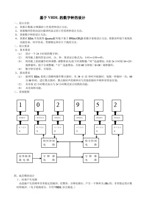
基于VHDL的数字钟的设计一、设计目的1、掌握计数器,分频器的工作原理和设计方法;2、掌握数码管的动态扫描译码显示的工作原理和设计方法;3、掌握数字钟的设计方法;4、掌握在EDA开发软件QuartusII环境下基于FPGA/CPLD的数字系统设计方法,掌握该环境下系统的功能仿真、时序仿真、管脚锁定和芯片下载的方法。
二、设计要求1、基本要求(1)设计一个24小时制的数字钟;(2)利用板上数码管显示时、分、秒,要求显示格式为:小时—分钟—秒;(3)利用板上的按键作时钟调整,调整要求为:按下时调整键,“时”迅速增加,并按24小时制(0~~23)规律循环;按下分调整键,“分”迅速增加,并按60分钟制(0~59)规律循环;(4)数字钟可清零、可保持。
2、提高要求(1)能利用EDA系统上的蜂鸣器作整点报时。
从59分55秒时开始报时,每隔一秒报时一次;00分00秒时,进行整点报时。
整点报时声的频率应与其他的报时声频率有明显区别;(2)具有按12小时模式显示与24小时模式显示切换的功能;(3)具有闹钟功能。
三、系统框图四、底层模块设计1、时基产生电路由晶振产生的频率非常稳定的脉冲,经整形、分频电路后,产生一个频率为1Hz的、非常稳定的计数时钟脉冲。
(电子线路部分,不用VHDL语言描述。
)2、校时电路(二选一数据选择器)LIBRARY ieee;USE ieee.std_logic_1164.all;ENTITY MUX2_1 ISPORT(K,CLK,CI : IN STD_LOGIC;Y : OUT STD_LOGIC);END MUX2_1;ARCHITECTURE b OF MUX2_1 ISBEGINY<=CLK WHEN K='0' ELSE CI;END b;3、计数器(1)24进制计数器1)24进制的VHDL语言程序LIBRARY ieee;USE ieee.std_logic_1164.all;USE ieee.std_logic_unsigned.all;ENTITY COUNT24 ISPORT(CLR : IN STD_LOGIC;EN : IN STD_LOGIC;CLK : IN STD_LOGIC;QL : BUFFER STD_LOGIC_VECTOR(3 downto 0);QH : BUFFER STD_LOGIC_VECTOR(3 downto 0);CO : OUT STD_LOGIC);END COUNT24;ARCHITECTURE a OF COUNT24 ISBEGINPROCESS(CLR,EN,CLK)BEGINIF CLR='0' THENQH<="0000";QL<="0000";ELSIF CLK'EVENT AND CLK='1' THENIF(EN='1')THENIF QH=2 AND QL=3 THENQL<="0000";QH<="0000";ELSEIF QL=9 THENQL<="0000";QH<=QH+1;ELSEQL<=QL+1;END IF;END IF;END IF;END IF;END PROCESS;CO<='0'WHEN QH=2 AND QL=3 ELSE'1';END a;2)仿真波形图1、count24的时序仿真波形3)从设计文件创建模块,默任模块的名称为count24。
文章编号:1671-251X(2006)03-0092-03基于VHDL 的多功能数字钟的设计樊永宁1, 张晓丽2(1.宁夏煤业集团有限责任公司,宁夏银川 750000;2.西安科技大学通信与信息工程学院,陕西西安 710054)摘要:介绍了利用VH DL 硬件描述语言设计的多功能数字钟的思路和技巧。
在MAX+PLU SII 开发环境中编译和仿真了所设计的程序,并在可编程逻辑器件上下载验证。
仿真和验证结果表明,该设计方法切实可行,具有一定的借鉴性。
关键词:数字钟;硬件描述语言;VH DL;MAX+PLUSII 中图分类号:TP39 文献标识码:B 0 引言随着电子设计自动化(EDA)的高速发展,电子系统的设计技术和工具发生了深刻的变化。
EDA 的关键技术之一是要求用形式化方式来描述数字系统的硬件电路,即要用所谓硬件描述语言来描述硬件电路。
本文即介绍如何利用V H DL 硬件描述语言设计一个具有年、月、日、时、分、秒计时显示、调整时间和整点报时功能的数字钟,并且利用MAX+PLU SII 开发环境进行编译、仿真,最终下载到可编程逻辑器件FPGA 上进行验证。
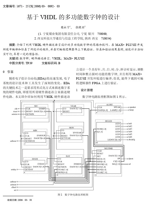
1 设计原理数字钟电路原理框图如图1所示。
图1 数字钟电路原理框图收稿日期:2006-03-30数字钟电路由秒、分、时、日、月、年6个计数模块和1个报警模块、1个时间数据动态扫描模块、1个显示译码模块组成。
设置计数年份从2000年到2099年,即年计数模块是1个100进制计数器。
秒计数模块的计数时钟clk为1H z的标准信号。
当数字钟处于正常计时状态时,秒计数器的进位输出信号enmin作为分钟模块的计数信号,分计数模块的进位输出enhour 作为小时模块的计数信号,依次,时进位输出en2 day,日进位输出enmon,月进位输出enyear,分别作为日、月、年的计数信号。
定义一个手动脉冲输入set。
当set=0时,数码管显示时、分、秒;当set=1时,数码管显示年、月、日。
V H D L数字时钟实验报告(共21页) -本页仅作为预览文档封面,使用时请删除本页-VHDL数字时钟设计一、实验目的:进一步练习VHDL语言设计工程的建立与仿真的步骤和方法、熟悉VHDL语言基本设计实体的编写方法。
同时,在已有知识的基础上,简单综合编写程序,仿制简单器械。
二、实验环境:PC个人计算机、Windows XP操作系统、Quartus II集成开发环境软件。
三、设计要求:运用VHDL语言编写一个数字钟,具体要求:1. 具有时、分、秒计数的十进制数字显示功能,以24小时循环计时。
2. 具有手动调节小时,分钟的功能。
3. 具有闹钟的功能,能够在设定的闹钟时间发出闹铃声。
四、实验步骤:1. 定义输入输出信号量port(clk:in std_logic; ---时钟speak:out std_logic; ---铃dout:out std_logic_vector(7 downto 0); ---晶体管显示setclk:in std_logic_vector(2 downto 0); ---操作按钮d1,d2,d3,d4,d5,d6: out std_logic); ---六个晶体管2. 定义结构体中的信号量signal sel:std_logic_vector(2 downto 0);signal hou1:std_logic_vector(3 downto 0); --时分秒的个位和十位signal hou2:std_logic_vector(3 downto 0);signal min1:std_logic_vector(3 downto 0);signal min2:std_logic_vector(3 downto 0);signal seth1:std_logic_vector(3 downto 0);signal seth2:std_logic_vector(3 downto 0);signal setm1:std_logic_vector(3 downto 0);signal setm2:std_logic_vector(3 downto 0);signal sec1:std_logic_vector(3 downto 0);signal sec2:std_logic_vector(3 downto 0);signal h1:std_logic_vector(3 downto 0);signal h2:std_logic_vector(3 downto 0);signal m1:std_logic_vector(3 downto 0);signal m2:std_logic_vector(3 downto 0);signal s1:std_logic_vector(3 downto 0);signal s2:std_logic_vector(3 downto 0);signal sph1,sph2,spm1,spm2,sps1,sps2:std_logic_vector(3 downto 0);signal count_sec:std_logic_vector(9 downto 0);signal sec_co :std_logic;signal co1,co2,co3,co4:std_logic; --进位signal switch :std_logic_vector(1 downto 0); --表示状态3. 分频模块用来定义秒count_sec用来计时钟个数,当count_sec=11时,及得到1Hz信号。
1 摘要本文介绍了利用VHDL硬件描述语言设计的多功能数字钟的思路和技巧。
本设计是一个多功能数字钟,具有计时、校时、清零等简单功能,在QuartusII 开发环境中编译和仿真了所设计的程序,并在可编程逻辑器件(ALTEA EPM7064SLI44-7)上下载验证。
关键字:QuartusII,数字钟, ALTEA EPM7064SLI44-7,VHDL2 引言随着电子设计自动化(EDA)的高速发展,电子系统的设计技术和工具发生了深刻的变化。
EDA的关键技术之一是要求用形式化方式来描述数字系统的硬件电路,即要用所谓硬件描述语言来描述硬件电路。
本文即介绍如何利用VHDL硬件描述语言设计一个具有时、分、秒计时显示、调整时间功能的数字钟,并且利用QuartusII开发环境进行编译、仿真,最终下载到可编程逻辑器件FPGA上进行验证。
3 实验要求设计制作一个多功能计时器,设计要求如下:1.计时功能:数字钟以24个小时为一个周期,必须显示时、分、秒。
2.清零功能:在板上设置一个手动清零开关,通过它可以对电路实现实时的手动清零。
3.校时功能:可随时对电路进行校时功能,并设置两个开关(a/b)控制。
按下a开关时(手不松开),数字时钟的秒钟数迅速增加(4HZ的时钟频率来驱动),并按60循环,计满60后再回00。
按下b开关时(手不松开),数字时钟的分钟数迅速增加(4HZ的时钟频率来驱动),并按60循环,计满60后再回00。
4 系统原理框图数字时钟实际上是一个对标准1Hz进行计时的计数电路,秒计数器满60后向分计数器进位,分计数器满60后向时计数器进位,时计数器按24翻1规律计数,计数输出经译码器送LED显示器,由于计数的起始时间不可能与标准时间一致,故需要在电路上加上一个校时电路。
5 各功能实现原理整个数字钟的设计包括七个模块,分别为分频、清零、计时、校时、BCD编码、扫描、译码,各模块的设计解决方案具体如下。
5.1 分频功能实现因为我们需要1HZ的频率来用来驱动秒计时器,而硬件提供的时钟频率是4HZ,所以我们要进行分频。
VHDL数字钟设计报告一. 数字钟总体设计方案:1.1设计目的①正确显示时、分、秒;②可手动校时,能分别进行时、分的校正;③整点报时功能;1.2设计思路数字钟的设计模块包括:分频器、去抖动电路、校时电路、“时、分、秒”计数器、校时闪烁电路、整点报时和译码显示电路。
每一个功能模块作为一个实体单独进行设计,最后再用VHDL的例化语句将各个模块进行整合,生成顶层实体top。
该数字钟可以实现3个功能:计时功能、设置时间功能和报时功能。
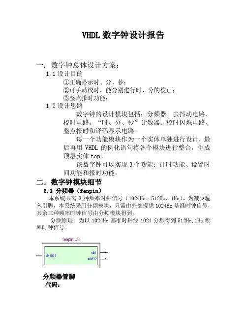
二.数字钟模块细节2.1 分频器(fenpin)本系统共需3种频率时钟信号(1024Hz、512Hz、1Hz)。
为减少输入引脚,本系统采用分频模块,只需由外部提供1024Hz基准时钟信号,其余三种频率时钟信号由分频模块得到。
分频原理:为以1024Hz基准时钟经1024分频得到512Hz,1Hz频率时钟信号。
分频器管脚代码:library ieee;use ieee.std_logic_1164.all;use ieee.std_logic_unsigned.all;use ieee.std_logic_arith.all;entity fenpin isport(clk1024:in std_logic;clk1,clk512:out std_logic);end fenpin ;architecture cml of fenpin isbeginprocess (clk1024)variable count1: integer range 0 to 512; variable q1: std_logic;beginif clk1024' event and clk1024='1' then if count1=512 thenq1:=not q1;count1:=0;elsecount1:=count1+1;end if;end if;clk1<=q1;end process;process(clk1024)variable count512: integer range 0 to 1; variable q512: std_logic;beginif clk1024' event and clk1024='1' thenif count512=1 thenq512:=not q512;count512:=0;elsecount512:=count512+1;end if;end if;clk512<=q512;end process;end cml;2.2 校时电路(jiaoshi)本模块要实现的功能是:正常计时、校时、校分在每个状态下都会产生不同控制信号实现相应的功能。
摘要VHDL作为一种硬件描述语言,可用于数字电路与系统的描述、模拟和自动设计与仿真等,是当今电子设计自动化的核心技术。
本文使用VHDL语言设计了一个数字时钟电路,给出了设计该数字系统的流程和方法。
本设计方法具有硬件描述能力强,设计方法灵活,便于修改等优点,大大降低了数字系统设计的难度,提高了工作效率。
本设计采用EDA技术,以硬件描述语言VHDL为系统逻辑描述手段设计文件,在MAX+PlusⅡ工具软件环境下,采用自顶向下的设计方法,由各个基本模块共同构建了一个基于CPLD的数字钟。
系统主芯片采用EPM7128SLC84,由时钟模块、控制模块、计时模块、数据译码模块、显示以及报时模块组成。
经编译和仿真所设计的程序,在可编程逻辑器件上下载验证,本系统能够完成时、分、秒的分别显示,由按键输入进行数字钟的校时、清零、启停功能。
关键词:硬件描述语言,VHDL,数字电路设计, 数字钟Digital Clock Design Based On The Hardware DescriptionLanguage(VHDL)Author: 。
Tutor: 。
AbstractVHDL can be used to describe,simulate and digital system automatically. Nowdays,it becomes a key technology in automatic electronic design. There is a lot of superiority in this description language.This article introduces the method and the process using VHDL to design a digital system by an example of digital clock dasign. The result given in this paper shows that VHDL is one of the strongest tools in hardware description and it is a flexible among the design method. The method given in this paper can reduce the difficulty of digital system design and improve the work efficiency.The use of EDA design technology, hardware-description language VHDL description logic means for the system design documents, in MaxplusII tools environment, a top-down design, by the various modules together build a CPLD-based digital clock.The main system chips used EPM7128SLC84, make up of the clock module, control module, time module, data decoding module, display and broadcast module. After compiling the design and simulation procedures, the programmable logic device to download verification, the system can complete the hours, minutes and seconds respectively, using keys to modify, cleared , start and stop the digital clock.Key words: Hardware description language,VHDL, Digital circuit design, digital clock目录1 绪论 (1)1.1课题背景 (1)1.2本课题研究的内容 (1)2 总体设计方案 (3)3 单元模块电路设计 (4)3.1时间显示电路模块设计 (4)3.2按键及指示灯电路模块的设计 (5)3.3蜂鸣器及有源晶振电路的设计 (7)3.4CPLD编程下载电路的设计 (8)3.5电源电路的设计 (9)3.5.1变压器次级电压估算 (9)3.5.2 变压器输入功率的计算 (9)3.5.3 滤波电容参数的选取 (10)3.6EPM7128SLC84器件介绍 (10)4 CPLD 编程设计 (11)4.1系统信号的定义及顶层模块 (11)4.2时钟节拍产生模块 (12)4.3模式选择功能模块 (14)4.4快速时间设置功能模块 (16)4.5秒、分、时计时与时间调整模块 (16)4.6闹铃时间设置模块 (18)4.7闹铃与整点报时模块 (19)4.8七段显示译码模块 (20)4.9LED显示模块 (22)5 系统功能仿真 (25)5.1时钟节拍产生模块的仿真波形 (25)5.2模式选择功能模块的仿真波形 (26)5.3闹铃设置功能模块的仿真波形 (27)5.4七段译码功能模块的仿真波形 (28)5.5LED显示功能模块的仿真波形 (30)5.6系统总体功能仿真波形 (31)总结 (32)致谢 (33)参考文献 (34)附录A:基于CPLD的多功能数字钟电路图 (35)附录B:基于VHDL语言的时、分、秒等电路的源码 (36)1绪论1.1 课题背景我们已经进入了数字化和信息化的时代,其特点是各种数字产品的广泛应用。
用verilog-HDL多功能数字钟Verilog HDL实验报告基于Verilog HDL语言的多功能数字钟设计一、试验目的设计一个有如下功能的数字钟:(1)计时功能:包括时、分、秒。
(2)定时与闹钟功能:能在所设定的时间发出铃音。
(3)校时功能:对小时、分钟和秒钟进行手动校时。
(4)整点报时功能:每到整点能够发出“嘀嘀嘀嘀嘟”四短一长的报时。
二、试验原理ALERT HOUR[7..0]MIN[7..0]SEC[7..0]LD_ALERT LD_HOUR LD_MINCLK CLK_1K MODE TURN CHANGEclockCLK CLK_1K MODE TURN CHANGEALERTHOUR[7..0]MIN[7..0]SEC[7..0]LD_ALERT LD_HOUR LD_MIN多功能数字钟端口示意图数字钟设有五个输入端,分别为时钟输入(CLK )、模式(MODE )、产生声音的时钟信号(CLK_1K )、切换(TURN )和调时(CHANGE )键。
输出共七个,其中HOUR[7..0]、MIN[7..0]和SEC[7..0]采用BCD 计数方式,分别驱动2个数码管。
硬件电路原理图如下:三、试验内容1. 代码/*信号定义:clk: 标准时钟信号,其频率为4Hz;clk_1k:产生闹铃声、报时音的时钟信号,其频率为1024Hz;mode:功能控制信号;为0:计时功能;为1:闹钟功能;为2:手动校时功能;turn:接按键,在手动校时功能时,选择是调整小时还是分钟;若长时间按住改建,还可使秒信号清零,用于精确调时;change: 接按键,手动调整时,每按一次,计数器加1;如果长按,则连续快速加1,用于快速调时和定时;hour,min,sec:此三信号分别输出并显示时、分、秒信号,皆采用BCD码计数,分别驱动6个数码管显示时间;alert:输出到扬声器的信号,用于产生闹铃音和报时音;闹铃音为持续20秒的急促的“嘀嘀嘀”音,若按住“change”键,则可屏蔽该音;整点报时音为“嘀嘀嘀嘀嘟”四短一长音;LD_alert:接发光二极管,指示是否设置了闹钟功能;LD_hour:接发光二极管,指示当前调整的是小时信号;LD_min:接发光二极管,指示当前调整的是分钟信号*/moduleclock(clk,clk_1k,mode,change,turn,alert,hour,min,sec,LD_alert,LD_hour,LD_mi n);input clk,clk_1k,mode,change,turn;output alert,LD_alert,LD_hour,LD_min;output[7:0] hour,min,sec;reg[7:0] hour,min,sec,hour1,min1,sec1,ahour,amin;reg[1:0] m,fm,num1,num2,num3,num4;reg[1:0] loop1,loop2,loop3,loop4,sound;reg LD_hour,LD_min;reg clk_1Hz,clk_2Hz,minclk,hclk;reg alert1,alert2,ear;reg count1,count2,counta,countb;wire ct1,ct2,cta,ctb,m_clk,h_clk;always @(posedge clk)beginclk_2Hz<=~clk_2Hz;if(sound==3) begin sound<=0; ear<=1; end //ear信号用于产生或屏蔽声音else begin sound<=sound+1; ear<=0; endendalways @(posedge clk_2Hz) //由4Hz的输入时钟产生1Hz的时基信号clk_1Hz<=~clk_1Hz;always @(posedge mode) //mode信号控制系统在三种功能间转换begin if(m==2) m<=0; else m<=m+1; endalways @(posedge turn)fm<=~fm;always //产生count1,count2,counta,countb四个信号begincase(m)2:begin if(fm)begin count1<=change; {LD_min,LD_hour}<=2; endelsebegin counta<=change; {LD_min,LD_hour}<=1; end{count2,countb}<=0;end1:begin if(fm)begin count2<=change; {LD_min,LD_hour}<=2; endelsebegin countb<=change; {LD_min,LD_hour}<=1; end{count1,counta}<=2'b00;enddefault:{count1,count2,counta,countb,LD_min,LD_hour}<=0;endcaseendalways @(negedge clk) //如果长时间按下“change”键,则生成“num1”信号用于连续快速加1if(count2) beginif(loop2==3) num2<=1;elsebegin loop2<=loop2+1; num2<=0;endendelse begin loop2<=0; num2<=0; endalways @(negedge clk) //产生num2信号if(count1) beginif(loop3==3) num3<=1;elsebegin loop3<=loop3+1; num3<=0; endendelse begin loop3<=0; num3<=0; endalways @(negedge clk)if(counta) beginif(loop4==3) num4<=1;elsebegin loop4<=loop4+1; num4<=0; endendelse begin loop4<=0; num4<=0; endassign ct1=(num3&clk)|(!num3&m_clk); //ct1用于计时、校时中的分钟计数assign ct2=(num1&clk)|(!num1&count2); //ct2用于在定时状态下调整分钟信号assign cta=(num4&clk)|(!num4&h_clk); //cta用于计时、校时中的小时计数assign ctb=(num2&clk)|(!num2&countb); //ctb用于在定时状态下调整小时信号always @(posedge clk_1Hz) //秒计时和秒调整进程if(!(sec1^8'h59)|turn&(!m))beginsec1<=0;if(!(turn&(!m))) minclk<=1;end//按住“turn”按键一段时间,秒信号可清零,该功能用于手动精确调时else beginif(sec1[3:0]==4'b1001)begin sec1[3:0]<=4'b0000; sec1[7:4]<=sec1[7:4]+1; endelse sec1[3:0]<=sec1[3:0]+1; minclk<=0;endassign m_clk=minclk||count1;always @(posedge ct1) //分计时和分调整进程beginif(min1==8'h59) begin min1<=0; hclk<=1; endelse beginif(min1[3:0]==9)begin min1[3:0]<=0; min1[7:4]<=min1[7:4]+1; endelse min1[3:0]<=min1[3:0]+1; hclk<=0;endendassign h_clk=hclk||counta;always @(posedge cta) //小时计时和小时调整进程if(hour1==8'h23) hour1<=0;else if(hour1[3:0]==9)begin hour1[7:0]<=hour1[7:4]+1; hour1[3:0]<=0; endelse hour1[3:0]<=hour1[3:0]+1;always @(posedge ct2) //闹钟定时功能中的分钟调节进程if(amin==8'h59) amin<=0;else if(amin[3:0]==9)begin amin[3:0]<=0; amin[7:4]<=amin[7:4]+1; endelse amin[3:0]<=amin[3:0]+1;always @(posedge ctb) //闹钟定时功能中的小时调节进程if(ahour==8'h23) ahour<=0;else if(ahour[3:0]==9)begin ahour[3:0]<=0; ahour[7:4]<=ahour[7:4]+1; endelse ahour[3:0]<=ahour[3:0]+1;always //闹铃功能if((min1==amin)&&(hour1==ahour)&&(amin|ahour)&&(!change))//若按住“change”键不放,可屏蔽闹铃音if(sec1<8'h20) alert1<=1; //控制闹铃的时间长短else alert1<=0;else alert1<=0;always //时、分、秒的现实控制case(m)3'b00: begin hour<=hour1; min<=min1; sec<=sec1; end//计时状态下的时、分、秒显示3'b01: begin hour<=ahour; min<=amin; sec<=8'hzz; end//定时状态下的时、分、秒显示3'b10: begin hour<=hour1; min<=min1; sec<=8'hzz; end//校时状态下的时、分、秒显示endcaseassign LD_alert=(ahour|amin)?1:0; //指示是否进行了闹铃定时assign alert=((alert1)?clk_1k&clk:0)|alert2; //产生闹铃音或整点报时音always //产生整点报时信号alert2beginif((min1==8'h59)&&(sec1>8'h54)||(!(min1|sec1)))if(sec1>8'h54) alert2<=ear&clk_1k; //产生短音else alert2<=!ear&clk_1k; //产生长音else alert2<=0;endendmodule2. 仿真图四、小结及体会为了做多功能数字钟,我借了多本关于Verilog HDL的程序设计书。
基于VHDL的多功效数字钟设计陈述021215班卫时章02121451一.设计请求1.具有以二十四小时制计时.显示.整点报时.时光设置和闹钟的功效.2.设计精度请求为1秒.二.设计情况:Quartus II三.体系功效描写1.体系输入:时钟旌旗灯号clk采取50MHz;体系状况及较时.准时转换的控制旌旗灯号为k.set,校时复位旌旗灯号为reset,均由按键旌旗灯号产生.2.体系输出:LED显示输出;蜂鸣器声音旌旗灯号输出.3.多功效数字电子钟体系功效的具体描写如下:(一)计时:正常工作状况下,每日按24h计时制计时并显示,蜂鸣器无声,逢整点报时.(二)校时:在计时显示状况下,按下“k”键,进入“小时”待校准状况,若此时按下“set”键,小时开端校准;之后按下“k”键则进入“分”待校准状况;中断按下“k”键则进入“秒”待复零状况;再次按下“k”键数码管显示闹钟时光,并进入闹钟“小时”待校准状况;再次按下“k”键则进入闹钟“分”待校准状况;若再按下“k”键恢复到正常计时显示状况.若校时进程中按下“reset”键,则体系恢复到正常计数状况.(1)“小时”校准状况:在“小时”校准状况下,显示“小时”的数码管以2Hz闪耀,并按下“set”键时以2Hz的频率递增计数.(2)“分”校准状况:在“分”校准状况下,显示“分”的数码管以2Hz闪耀,并按下“set”键时以2Hz的频率递增计数.(3)“秒”校准状况:在“秒复零”状况下,显示“秒”的数码管以2Hz闪耀,并以1Hz的频率递增计数.(4)闹钟“小时”校准状况:在闹钟“小时”校准状况下,显示“小时”的数码管以2Hz闪耀,并按下“set”键时以2Hz的频率递增计数.(5)闹钟“分”校准状况:在闹钟“分”校准状况下,显示“分”的数码管以2Hz闪耀,并按下“set”键时以2Hz的频率递增计数.(三)整点报时:蜂鸣器在“59”分钟的第“51”.“53”.“55”.“57”秒发频率为500Hz的低音,在“59”分钟的第“59”秒发频率为1000Hz的高音,停止时为整点.(四)显示:采取扫描显示方法驱动4个LED数码管显示小时.分,秒由两组led灯以4位BCD 码显示.(五)闹钟:闹钟准不时光到,蜂鸣器发出频率为1000Hz的高音,中断时光为60秒.四.各个模块剖析解释1.分频器模块(freq.vhd)(1)模块解释:输入一个频率为50MHz的CLK,应用计数器分出1KHz的q1KHz,500Hz的q500Hz,2Hz的q2Hz和1Hz的q1Hz.(2)源程序:library ieee;use ieee.std_logic_1164.all;use ieee.std_logic_unsigned.all;entity freq isport (CLK: in std_logic ; --输入时钟旌旗灯号q1KHz: buffer std_logic;q500Hz: buffer std_logic;q2Hz: buffer std_logic;q1Hz: out std_logic);end freq;architecture bhv of freq isbeginP1KHZ:process(CLK)variable cout:integer:=0;beginif CLK'event and CLK='1' thencout:=cout+1; --每来个时钟上升沿时cout开端计数if cout<=25000 then q1KHz<='0'; --当cout<=25000时,q1KHz输出“0”elsif cout<50000 then q1KHz<='1'; --当25000<cout<=50000时,q1KHzelse cout:=0; --输出“1”,完成1KHz 频率输出end if;end if;end process;P500HZ:process(q1KHz) --q1KHz作为输入旌旗灯号,分出q500Hzvariable cout:integer:=0;beginif q1KHz'event and q1KHz='1' thencout:=cout+1;if cout=1 then q500Hz<='0'; --二分频elsif cout=2 then cout:=0;q500Hz<='1';end if;end if;end process;P2HZ:process(q500Hz)variable cout:integer:=0;beginif q500Hz'event and q500Hz='1' then cout:=cout+1;if cout<=125 then q2Hz<='0';elsif cout<250 then q2Hz<='1';else cout:=0;end if;end if;end process;P1HZ:process(q2Hz)variable cout:integer:=0;beginif q2Hz'event and q2Hz='1' thencout:=cout+1;if cout=1 then q1Hz<='0';elsif cout=2 then cout:=0;q1Hz<='1'; end if;end if;end process;end bhv;(3)模块图:2.控制器模块(contral.vhd)(1)模块解释:输入端口k,set键来控制6个状况,这六个状况分离是:显示计不时光状况,调计时的时.分.秒的3个状况,调闹铃的时.分的3个状况,reset键是复位键,用往返到显示计不时光的状况.(2)波形仿真图:(3)模块图:3、二选一模块(mux21a.vhd)(1)源程序:library ieee;use ieee.std_logic_1164.all;use ieee.std_logic_unsigned.all;entity mux21a isport(a,b,s:in bit;y:out bit);end entity mux21a;architecture one of mux21a isbeginprocess(a,b,s)beginif s='0' theny<=a; --若s=0,y输出a,反之输出b. else y<=b;end if;end process;end architecture one;(2)仿真波形图:(3)模块图:4、计时模块a.秒计时(second.vhd)(1)仿真波形图:(2)模块图:b.分计时(minute.vhd)(1)仿真波形图:(2)模块图:c.小时计时(hour.vhd)(1)仿真波形图:(2)模块图:d.闹钟分计时(cntm60b.vhd)(1)仿真波形图:(2)模块图:e.闹钟小时计时(cnth24b.vhd)(1)仿真波形图:(2)模块图:5.闹钟比较模块(compare.vhd)(1)模块解释:比较正常计数时光与闹钟准不时光是否相等,若相等,compout输出“1”,反之输出“0”.(2)仿真波形图:(3)模块图:6.报时模块(bell.vhd)(1)模块解释:该模块既实现了整点报时的功效,又实现了闹铃的功效,蜂鸣器经由过程所选频率的不合,而发出不合的声音.(2)仿真波形图:(3)模块图:7.控制显示模块(show_con.vhd)(1)模块解释:该模块实现了数码管既可以显示正常时光,又可以显示闹钟时光的功效;调时进程的准时闪耀功效也在此模块中真正实现.(2)源程序:library ieee;use ieee.std_logic_1164.all;use ieee.std_logic_unsigned.all;entity show_con isport(th1,tm1,ts1:in std_logic_vector(7 downto 4);th0,tm0,ts0:in std_logic_vector(3 downto 0);bh1,bm1:in std_logic_vector(7 downto 4);bh0,bm0:in std_logic_vector(3 downto 0);sec1,min1,h1: out std_logic_vector(7 downto 4);sec0,min0,h0: out std_logic_vector(3 downto 0);q2Hz,flashs,flashh,flashm,sel_show:in std_logic); end show_con;architecture rtl of show_con isbeginprocess(th1,tm1,ts1,th0,tm0,ts0,bh1,bm1,bh0,bm0,q2Hz,flas hs,flashh,flashm,sel_show)beginif sel_show='0'thenif ( flashh='1'and q2Hz='1')thenh1<="1111";h0<="1111"; --显示小时数码管以2Hz闪耀min1<=tm1;min0<=tm0;sec1<=ts1;sec0<=ts0;elsif (flashm='1'and q2Hz='1')thenh1<=th1;h0<=th0;min1<="1111";min0<="1111";sec1<=ts1;sec0<=ts0;elsif (flashs='1'and q2Hz='1')thenh1<=th1;h0<=th0;min1<=tm1;min0<=tm0;sec1<="1111";sec0<="1111";elseh1<=th1;h0<=th0;min1<=tm1;min0<=tm0;sec1<=ts1;sec0<=ts0;end if;elsif sel_show='1'then--若sel_show为“1”,数码管显示闹钟时光if(flashh='1' and q2Hz='1')thenh1<="1111";h0<="1111";min1<=bm1;min0<=bm0;sec1<="0000";sec0<="0000";elsif ( flashm='1' and q2Hz='1')thenh1<=bh1;h0<=bh0;min1<="1111";min0<="1111";sec1<="0000";sec0<="0000";elseh1<=bh1;h0<=bh0;min1<=bm1;min0<=bm0;sec1<="0000";sec0<="0000";end if ;end if;end process;end rtl;(3)模块图:8.动态扫描显示模块(scan_led.vhd)(1)模块解释:由4组输入旌旗灯号和输出旌旗灯号进而实现了时钟时.分的动态显示.(2)源程序:library ieee;use ieee.std_logic_1164.all;use ieee.std_logic_unsigned.all;entity scan_led isport(clk1:in std_logic;h0:in std_logic_vector(3 downto 0);h1:in std_logic_vector(7 downto 4);min0:in std_logic_vector(3 downto 0);min1:in std_logic_vector(7 downto 4);ML:out std_logic_vector(7 downto 0);MH:out std_logic_vector(7 downto 0);HL:out std_logic_vector(7 downto 0);HH:out std_logic_vector(7 downto 0));end scan_led;architecture one of scan_led issignal cnt4:std_logic_vector(1 downto 0);signal a: std_logic_vector(3 downto 0) ;beginp1:process(clk1)beginif clk1'event and clk1 ='1' thencnt4<=cnt4+1;if cnt4=3 thencnt4<="00";end if;end if;end process p1;p2:process(cnt4,h1,h0,min1,min0)begincase cnt4 is --控制数码管位选when "00"=>case min0 iswhen "0000"=>ML<="11000000";when "0001"=>ML<="11111001";when "0010"=>ML<="10100100";when "0011"=>ML<="10110000";when "0100"=>ML<="10011001";when "0101"=>ML<="10010010";when "0110"=>ML<="10000010";when "0111"=>ML<="11111000";when "1000"=>ML<="10000000";when "1001"=>ML<="10010000";when others=>NULL;end case;when "01"=>case min1 iswhen "0000"=>MH<="11000000"; when "0001"=>MH<="11111001";when "0010"=>MH<="10100100";when "0011"=>MH<="10110000";when "0100"=>MH<="10011001";when "0101"=>MH<="10010010";when "0110"=>MH<="10000010";when "0111"=>MH<="11111000";when "1000"=>MH<="10000000";when "1001"=>MH<="10010000";when others=>NULL;end case;when "10"=>case h0 iswhen "0000"=>HL<="11000000"; when "0001"=>HL<="11111001";when "0010"=>HL<="10100100";when "0011"=>HL<="10110000";when "0100"=>HL<="10011001";when "0101"=>HL<="10010010";when "0110"=>HL<="10000010";when "0111"=>HL<="11111000";when "1000"=>HL<="10000000";when "1001"=>HL<="10010000";when others=>NULL;end case;when "11"=>case h1 iswhen "0000"=>HH<="11000000"; when "0001"=>HH<="11111001";when "0010"=>HH<="10100100";when "0011"=>HH<="10110000";when "0100"=>HH<="10011001";when "0101"=>HH<="10010010";when "0110"=>HH<="10000010";when "0111"=>HH<="11111000";when "1000"=>HH<="10000000";when "1001"=>HH<="10010000";when others=>NULL;end case;when others =>null;end case;end process p2;end one;(3)模块图:五、端口设定k:button2 ,set:button1 ,reset:button0 ;Bell:SW1 用于开关蜂鸣器;六.顶层电路图七、心得领会此次的数字钟设计重在于按键的控制和各个模块代码的编写,固然能把键盘接口和各个模块的代码编写出来,并能正常显示,但对于各个模块的优化设计还有必定的缺点和缺少,比方对按键消抖等细节处并未作出优化.经由此次数字钟的设计,我确切从中学到许多的器械.起首,经由过程VHDL硬件说话的进修,我充分熟悉到了功效模块若何用说话实现,让我初步懂得到了一个数字电路用硬件说话设计的方法和设计思惟.其次,也让我深深地领会到实践的主要性,起先我学VHDL说话的时刻,只是学得书本上的常识,经由此次课程设计,经由过程对模块的说话实现,对于VHDL说话我有了更深的熟悉.并且在程序错误的发明和纠正的进程中,我得到了更多的收成,也确切让我提高了许多.再次,当我碰到一些问题的时刻,就教先生,和同窗们一路评论辩论,令我受益颇多!最后,这个多功效数字电子钟是自我创造与汲取借鉴配合感化的产品,是自我尽力的成果.这让我对数字电路的设计充满了信念.固然课程设计已经停止,但这其实不代表着我已经真正控制了VHDL说话,仍需中断进修!。
目录1 概述...................................................................... 错误!未定义书签。
1.1数字时钟的工作原理 (1)1.2设计任务 (1)2 系统总体方案设计 (2)3 VHDL模块电路设计 (3)3.1模块实现 (3)3.1.1分频模块pinlv (3)3.1.2按键去抖动模块qudou (5)3.1.3按键控制模块self1 (6)3.1.4秒、分六十进制模块cantsixty (7)3.1.5时计数模块hourtwenty (9)3.1.6秒、分、时组合后的模块 (9)3.1.7数码管显示模块 (10)3.2数字时钟的顶层设计原理图 (13)3.3系统仿真与调试 (14)结束语 (16)参考文献 (17)致谢 (18)附录源程序代码 (19)1 概述1.1数字时钟的工作原理数字钟电路的基本结构由两个60进制计数器和一个24进制计数器组成,分别对秒、分、小时进行计时,当计时到23时59分59秒时,再来一个计数脉冲,则计数器清零,重新开始计时。
秒计数器的计数时钟CLK为1Hz的标准信号,可以由晶振产生的50MHz信号通过分频得到。
当数字钟处于计时状态时,秒计数器的进位输出信号作为分钟计数器的计数信号,分钟计数器的进位输出信号又作为小时计数器的计数信号,每一秒钟发出一个中断给CPU,CPU采用NIOS,它响应中断,并读出小时、分、秒等信息。
CPU对读出的数据译码,使之动态显示在数码管上。
1.2 设计任务设计一个基于VHDL的数字时钟,具体功能要求如下:1.在七段数码管上具有时--分--秒的依次显示。
2.时、分、秒的个位记满十向高位进一,分、秒的十位记满五向高位进一,小时按24进制计数,分、秒按60进制计数。
3.整点报时,当计数到整点时扬声器发出响声。
4.时间设置:可以通过按键手动调节秒和分的数值。
此功能中可通过按键实现整体清零和暂停的功能。
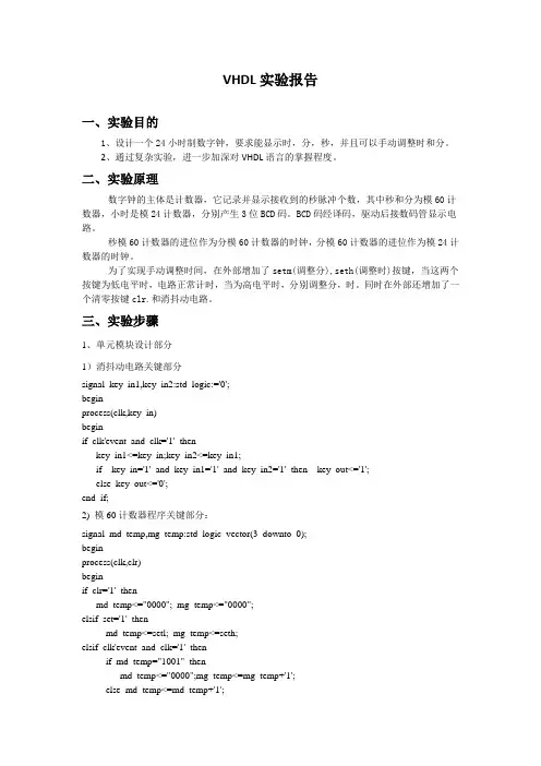
VHDL实验报告一、实验目的1、设计一个24小时制数字钟,要求能显示时,分,秒,并且可以手动调整时和分。
2、通过复杂实验,进一步加深对VHDL语言的掌握程度。
二、实验原理数字钟的主体是计数器,它记录并显示接收到的秒脉冲个数,其中秒和分为模60计数器,小时是模24计数器,分别产生3位BCD码。
BCD码经译码,驱动后接数码管显示电路。
秒模60计数器的进位作为分模60计数器的时钟,分模60计数器的进位作为模24计数器的时钟。
为了实现手动调整时间,在外部增加了setm(调整分),seth(调整时)按键,当这两个按键为低电平时,电路正常计时,当为高电平时,分别调整分,时。
同时在外部还增加了一个清零按键clr.和消抖动电路。
三、实验步骤1、单元模块设计部分1)消抖动电路关键部分signal key_in1,key_in2:std_logic:='0';beginprocess(clk,key_in)beginif clk'event and clk='1' thenkey_in1<=key_in;key_in2<=key_in1;if key_in='1' and key_in1='1' and key_in2='1' then key_out<='1';else key_out<='0';end if;2) 模60计数器程序关键部分:signal md_temp,mg_temp:std_logic_vector(3 downto 0);beginprocess(clk,clr)beginif clr='1' thenmd_temp<="0000"; mg_temp<="0000";elsif set='1' thenmd_temp<=setl; mg_temp<=seth;elsif clk'event and clk='1' thenif md_temp="1001" thenmd_temp<="0000";mg_temp<=mg_temp+'1';else md_temp<=md_temp+'1';if md_temp="1001" and mg_temp="0101" thenmd_temp<="0000";mg_temp<="0000";2、模24计数器程序关键部分signal hd_temp,hg_temp:std_logic_vector(3 downto 0);beginprocess(clk,clr,set,setl,seth)isbeginif set='1' then hd_temp<=setl; hg_temp<=seth;elsif clr='1' then hd_temp<="0000"; hg_temp<="0000";elsif clk'event and clk='1' thenif hg_temp="0010" and hd_temp="0011" thenhd_temp<="0000"; hg_temp<="0000";elsif hd_temp="1001" thenhg_temp<=hg_temp+'1' hd_temp<="0000";else hd_temp<=hd_temp+'1';end if;end if;end process ;3、清零和调时部分显示部分关键程序process (sd,sg,md,mg,hd,hg)begincase sd iswhen "0000" =>sl<="1111110";when "0001" =>sl<="0110000";when "0010" =>sl<="1101101";when "0011" =>sl<="1111001";when "0100" =>sl<="0110011";when "0101" =>sl<="1011011";when "0110" =>sl<="1011111";when "0111" =>sl<="1110000";when "1000" =>sl<="1111111";when "1001" =>sl<="1111011";when others =>sl<="0000000";end case;if clk_g'event and clk_g='1' thenif sel="101" thensel<="000";else sel<=sel+'1';end if;end if;process(sel,sd,sl,sg,sh,md,ml,mg,mh,hd,hl,hg,hh)begincase sel iswhen"000"=>led<=sl;led_which<=sd;when"001"=>led<=sh;led_which<=sg;when"010"=>led<=ml;led_which<=md;when"011"=>led<=mh;led_which<=mg;when"100"=>led<=hl;led_which<=hd;when"101"=>led<=hh;led_which<=hg;when others=>led<="0000000";led_which<="0000";end case;4、顶层文件关键程序port(clk,clk_g:in std_logic;-----clk_g是用在数码管显示里面的信号clr: in std_logic;------clr=1时清零setm,seth:in std_logic;---------setm为1时调分,seth为1时调时setd,setg:in std_logic_vector(3 downto 0);----调整时间的时候,setd调整的是低位setg 调整高位led:out std_logic_vector(6 downto 0);sel_out: out std_logic_vector(2 downto 0);led_which: out std_logic_vector(3 downto 0));---输出的是秒分时的哪一个beginu1:de_shake port map (clk=>clk,key_in=>clr,key_out=>clro);u2:de_shake port map (clk=>clk,key_in=>setm,key_out=>setmo);u3:de_shake port map (clk=>clk,key_in=>seth,key_out=>setho);u4:s60 port map (clk=>clk,clr=>clro,sd=>sdl,sg=>sgh,fenmaichong=>fenmaichong o);u5:m60 port map (clk=>fenmaichongo,clr=>clro,md=>mdl,mg=>mgh,xiaoshimaichong=> xiaoshimaichongo,setl=>setd,seth=>setg,set=>setmo);u6:h24 port map (clk=>xiaoshimaichongo,clr=>clro,hd=>hdl,hg=>hgh,set=>setho,se tl=>setd,seth=>setg);u7:led_xs port map (clk_g=>clk_g,sd=>sdl,sg=>sgh,md=>mdl,mg=>mgh,hd=>hdl, hg=>hgh,led=>led,sel_out=>sel_out,led_which=>led_which);四、实验结果及分析本设计,满足了本次试验设计的任务要求,能显示时分秒,并且可以手动调节分和时。
基于VHDL的数字电子钟系统设计数字电子钟是一种用数字电路实现的时钟系统,在现代社会逐渐普及。
在这篇文档中,我们将会讨论使用VHDL(可编程硬件描述语言) 设计数字电子钟系统的过程及其原理。
第一步是需求分析。
我们需要决定所设计的数字电子钟系统需要具备哪些功能,例如显示小时、分钟、秒数、日期、星期、闹钟等功能。
同时,还需考虑设计的电子钟具备哪些功能是其他电子钟所没有的,以增强该款电子钟的市场竞争力。
第二步是架构设计。
经过需求分析后,我们需要设计电子钟系统所需的硬件结构。
常见的电子钟由振荡器、时钟、存储器、显示器和控制接口组成。
其中,振荡器用来处理系统时基;时钟用来计时,提供系统时间;存储器负责存储显示数据和助记代码;显示器用来显示时间和日期;而控制接口则提供交互方式,如按键、通讯口等。
第三步是模块设计。
使用VHDL 可以将架构设计分解成更小的模块,进行编写和测试。
这些模块可以包括时钟模块、计数器模块、闹钟模块、数据显示模块等。
其中,时钟模块需要使用振荡器生成时钟信号,计数器模块必须进行计时,生成秒数和毫秒数的输出信号;然后,使用数码管显示模块将这些输出信号转换成可读的时间、日期和闹钟信息;再添加按键输入模块,以便用户操作和控制该电子钟系统。
第四步是系统测试。
在VHDL 设计结束后,需要对数字电子钟系统进行实际测试。
首先,系统测试需要用到仿真软件对整个系统进行验证。
同时,需要将程序下载到FPGA 芯片上,并通过硬件测试验证设计的电子钟系统是否符合需求和规范。
综上所述,设计数字电子钟系统需要遵循一定的流程,包括需求分析、架构设计和模块设计,在这个过程中也需要注重各个模块之间的兼容性和整体性。
这篇文档给大家介绍了使用VHDL 搭建数字电子钟系统的方法,希望广大读者可以从中获得借鉴。
摘要摘要随着EDA技术的发展和应用领域的扩大与深入,EDA技术在电子信息、通信、自动控制及计算机应用领域的重要性日益突出。
EDA技术就是依赖功能强大的计算机,在EDA工具软件平台上,对以硬件描述语言VHDL为系统逻辑描述手段完成的设计文件,自动地完成逻辑优化和仿真测试,直至实现既定的电子线路系统功能。
本文介绍了基于VHDL硬件描述语言设计的多功能数字闹钟的思路和技巧。
在Quartus 11开发环境中编译和仿真了所设计的程序,并逐一调试验证程序的运行状况。
仿真和验证的结果表明,该设计方法切实可行,该数字闹钟可以实现调时定时闹钟播放音乐功能具有一定的实际应用性。
关键词:闹钟 FPGA VHDL目录目录摘要............................................................................................................................. I 目录.......................................................................................................................... III 第一章选题背景.. (1)1.1选题研究内容 (1)1.2课题研究功能 (1)1.3课题相关技术应用 (1)第二章FPGA 简介 (3)2.1FPGA概述 (3)2.1.1 FPGA基本结构 (3)2.2FPGA编程原理 (3)2.3FPGA设计流程 (4)第三章数字闹钟整体方案设计 (7)3.1数字闹钟整体设计 (7)3.1.1数字闹钟各部分作用 (7)3.2数字钟的工作原理 (7)第四章模块电路设计 (9)4.1模块电路图设计 (9)4.2各模块电路设计 (9)第五章实验结果 (16)5.1实验概述 (16)5.2实验仿真结果 (16)第六章总结与展望 (18)研究结论 (18)研究展望 (18)致谢 (20)参考文献 (22)附录1 部分模块代码 (24)附录2 动态扫描模块程序 (33)目录第一章选题背景第一章选题背景1.1选题研究内容设计一个24小时的闹钟,该闹钟由显示屏、数字键、TIME键、ALARM键、扬声器组成。
西安欧亚学院本科毕业论文(设计)题目:基于VHDL的多功能数字钟设计学生姓名:指导教师:所在分院:专业:班级:二O 年月基于VHDL的多功能数字钟设计摘要:本设计为一个多功能的数字钟,具有时、分、秒计数显示功能、校时功能、定时闹钟功能以及校园打铃功能。
此数字钟是一个将“时”、“分”、“秒”显示于人的视觉器官的计时装置,它的计时周期为24小时,显示满刻度为23时59分59秒;校时功能可以根据需要自行设置时间;本课题还应定时闹铃功能,可以在任意时间响闹铃;此外,本课题具有校园打铃功能,即在每天固定时间(春季和夏季作息时间不同)响铃20s。
本设计采用EDA技术,以硬件描述语言VHDL为系统逻辑描述手段设计文件,在Quartus II 9.0工具软件环境下,采用自顶向下的设计方法,由各个基本模块共同构建了一个基于FPGA的数字钟。
硬件系统主芯片采用EP1C6TC144,整个软件方案由时钟模块、控制模块、计时模块、数据译码模块、显示以及报时模块组成。
经编译和仿真所设计的程序,在可编程逻辑器件上下载验证。
本系统用晶体振荡器产生时间标准信号,这里采用石英晶体振荡器,然后经过分频得到需要的秒计时信号。
根据60秒为1分、60分为1小时、24小时为1天的计数周期,分别组成两个60进制(秒、分)、一个24进制(时)的计数器,构成秒、分、时的计数,实现计时的功能。
显示器件选用LED七段数码管,在译码显示电路输出的驱动下,显示出清晰、直观的数字符号。
关键词:数字钟;硬件描述语言;VHDL;FPGA;键盘接口Multi-Functional Digital Clock Basedon VHDLAbstract: The propose of this thesis is to design a multi-functional digitalclock with the hour, minute and second display function, time adjusting function, the alarm function and the campus ring function. This digital clock can display hour, minute and second, which has an timing period of 24 hours, and the maximum time is 23:59:59. With time adjusting function, one can set arbitrary time manually. This clock should also have alarm function that can ring at desired time. Besides, this design can be used as a campus ring system, i.e. ring at pre-setted time, which is different at spring and autumn.This design is based on EDA technique, and use VHDL as the programing language. In Quartus II 9.0, we use the Down design method, and constitute a digital clock with several basic blocks. The main hardware IC is EP1C6TC144, and the software scheme contains blocks such as clock block, control block, timing block, LED decoding block, display block and ring block. After compile and simulation, we download the software to FPGA chip. This system need oscillator to generate standard time, then get second signal after frequency division. In corroding to the rule that there are 60 seconds in a minute, 60 minutes in a hour, and 24 hours in a day, we need two 60 counter and one 24 counter to implement the clock function. We choose LED as the display component, which can display clear and ocular digital symbol under the control of LED decoding circuit.Keywords: digital clock; hardware description language; VHDL; FPGA; keyboard interface目录1 绪论 (1)1.1 选题背景 (2)1.1.1 课题相关技术的发展 (2)1.1.2 课题研究的必要性 (3)1.1设计功能要求 (4)1.2 课题研究的内容 (4)2 FPGA开发流程简介 (5)2.1 FPGA概述 (5)2.2 FPGA基本结构 (5)2.3 FPGA系统设计流程 (8)2.4 FPGA开发编程原理 (10)3 数字钟总体设计方案 (11)3.1 系统方案的选择 (11)3.2 数字钟的构成 (14)3.2 数字钟的工作原理 (16)4 单元电路设计 (17)4.1 分频模块电路设计与实现 (17)4.2 校时控制模块电路设计与实现 (19)4.2.1 键盘接口电路原理 (19)4.2.2 键盘接口的VHDL描述 (20)4.3 计数模块设计与实现 (25)4.3.1 秒和分计数模块 (25)4.3.2 时计数模块 (27)4.3.3 时钟校时模块 (29)4.3.3 带校时功能的整体时钟模块 (30)4.4 定时闹铃模块 (32)4.4.1 闹铃控制模块 (32)4.4.2 闹铃比较模块 (34)4.5 校园打铃闹铃模块 (35)4.5.1 校园打铃模块 (35)4.5.2 打铃时间调整模块 (38)4.6 显示电路设计与实现 (39)5 结论与研究展望 (46)5.1 结论 (46)5.2 研究展望 (48)致谢 (49)参考文献 (50)1 绪论现代社会的标志之一就是信息产品的广泛使用,而且是产品的性能越来越强,复杂程度越来越高,更新步伐越来越快。
数字系统课程设计报告课程设计题目:基于vhdl语言的电子钟组员:陈洪彬,麦俊辉,缪超课程设计要求:设计一个用4位数码管显示的电子钟,包括整点报时,闹钟功能,4按键输入采用 VHDL 语言描述系统功能,并在 QUARTUS II 工具软件中进行仿真,下载到 EDA 实验板进行验证。
编写设计报告,要求包括方案选择、程序代码清单、调试过程、测试结果及心得体会。
一、软硬件资源分析实验室提供了Altera公司的cyclone系列EP1C6Q240C8实验开发板,该开发板提供了四个自由按键,八个发光LED,蜂鸣器,四个七段数码管,四位拨码开关等等硬件资源。
我们所设计的数字钟用到了四个自由按键用于对显示的选择,对设置时间的选择,还有用于用于设置时间时的加一操作,四个七段数码管用于显示,蜂鸣器用于整点报时和闹钟,还有四个发光LED用于判断自由按键的通断。
以下列表对数字钟中用到的硬件资源进行说明:下表)抖自由按键Key4in Key3 P_128 修改时间时加一,停止闹钟长按一下脉冲来时改变,消抖七段数码管dout,selout 7LED1_C1~C3 P_168P_169P_170P_173 显示正常时间及修改状态动态扫描法实现显示四个数码管全用总体设计框图:操作说明:按键状态Key4out Key3out Key2out Key1out 实现功能上升沿 1 0 0 修改小时(时钟)上升沿 1 1 0 修改分钟(时钟)上升沿 1 0 1 修改小时(闹钟)上升沿 1 1 1 修改分钟(闹钟)X(0或1)0 1 0 显示时分(时钟)x 0 0 0 显示分秒(时钟)x 0 0 1 显示时分(闹钟)x 0 1 1 显示分(闹钟)Key1的1表示闹钟,0表示时钟;Key2则是‘时-分’切换或者‘时分-分秒’切换。
各模块介绍(1)分频器在数字钟的设计中,采用了芯片内部提供的50MHz 全局时钟,将其分频率后产生一个接近 1Hz秒时钟 clk1,一个 2Hz 左右的闪烁时钟clk2,一个显示模块800Hz的clk3,一个用于消抖模块的20000Hz的clk4。
本科实验报告题目:数字钟课程名称:学院(系):专业:班级:学生姓名:学号:完成日期:成绩:2011 年12 月12 日题目:数字钟1 设计要求系统功能:1.计时,数码管显示的‘时’、‘分’、‘秒’的十进制数字显示(小时从00~23)计时器2.星期,lcd1602显示星期:MON/TUE/WEN/THU/FRI/SAT/SUN3.校准,具有手动校星期、校时、校分、校秒的功能。
4.秒表,显示1%秒、60秒,60分,能手动开始和停止5.闹钟,能在设定的时间发出闹铃声。
6.整点报时,即从59分55秒起,每隔1秒钟发出一次低音“嘟”的信号,连续2次,最后一次为高音“嘀”的信号,此信号结束即达到整点,发音的同时伴有led闪烁。
7.倒计时,能在设定的时间开始倒计时,至0时0分0秒停止2 设计分析及系统方案设计一.设计分析:依据功能要求,程序分为:1.计时与校准模块①计时:秒钟计数到59后清零并向分钟进一位,分钟计数到59后清零并向时钟进一位,时钟计数到23后清零并向星期进一位,星期按照MON/TUE/WEN/THU/FRI/SAT/SUN循环变化②校准:使用k1/k0两个功能键,k1切换要改变的位,k0校正2.数码管显示模块①显示译码②利用k3切换显示内容,根据不同模式关闭用不到的数码管。
3.lcd显示模块①定义七个常量数组,数组内容分别为MON/TUE/WEN/THU/FRI/SAT/SUN的ASCⅡ码。
②液晶初始化③液晶显示,将相应字母的ASCⅡ码写入ddram的相应地址中,由cnt1值决定地址,cnt1由0到2循环,因此用到lcd开始的前三个位显示字符。
由星期(m)值决定写入内容,m值不同,cnt1扫描显示的就是不同的数组。
4.闹钟与整点报时模块①整点报时:利用分频得到1k和的频率,当分钟位到达‘59’,秒钟位为‘55’、‘57’时,将频率接到输出引脚,秒钟位为‘59’时,将1k频率接到输出引脚。
②闹钟:到达闹钟时间,将1k频率接到输出引脚,时长3秒③Led闪烁:将led输出引脚连接至频率输出引脚即可(设为inout)5.秒表模块①开启显示1%秒、60秒、60分的数码管。
设计报告课程名称在系统编程技术任课教师查长军设计题目数字时钟班级通信(1)班姓名王兵学号0805070345 日期2011、5、18目录摘要: (1)关键词:数字钟 EDA VHDL语言 (1)一、设计目的 (1)二、设计内容 (1)三、设计原理 (2)1、数字钟的基本工作原理: (2)2、数字钟设计的电路原理图 (3)3、VHDL 设计 (3)四、设计仪器、设备 (4)五、设计步骤 (5)1、用VHDL程序设计 (5)步骤1:为本项设计建立文件夹 (5)步骤2:输入设计项目和存盘 (5)步骤3:选择目标器件并编译 (6)步骤4:时序仿真 (6)步骤5:引脚锁定 (9)步骤6:编程下载 (9)2、实验箱显示 (10)六、总结 (11)参考文献 (11)附录: (11)摘要:人类社会已进入到高度发达的信息化社会。
信息化社会的发展离不开电子信息产品开发技术、产品品质的提高和进步。
电子信息产品随着科学技术的进步,其电子器件和设计方法更新换代的速度日新月异。
实现这种进步的主要原因就是电子设计技术和电子制造技术的发展,其核心就是电子设计自动化(EDA,Electronics Design Automation)技术,EDA 技术的发展和推广应用又极大地推动了电子信息产业的发展。
为保证电子系统设计的速度和质量,适应“第一时间推出产品”的设计要求,EDA技术正逐渐成为不可缺少的一项先进技术和重要工具。
目前,在国内电子技术教学和产业界的技术推广中已形成“EDA热”,完全可以说,掌握EDA技术是电子信息类专业学生、工程技术人员所必备的基本能力和技能。
EDA技术在电子系统设计领域越来越普及,本设计主要利用VHDL语言在EDA平台上设计一个电子数字钟,它的计时周期为24小时,显示满刻度为24时59分59秒,另外还具有校时功能和闹钟功能。
总的程序由几个各具不同功能的单元模块程序拼接而成,其中包括分频程序模块、时分秒计数和设置程序模块、比较器程序模块、三输入数据选择器程序模块、译码显示程序模块和拼接程序模块。
基于VHDL的多功能数字钟设计报告021215班卫时章02121451一、设计要求1、具有以二十四小时制计时、显示、整点报时、时间设置和闹钟的功能。
2、设计精度要求为1秒。
二、设计环境:Quartus II三、系统功能描述1、系统输入:时钟信号clk采用50MHz;系统状态及较时、定时转换的控制信号为k、set,校时复位信号为reset,均由按键信号产生。
2、系统输出:LED显示输出;蜂鸣器声音信号输出。
3、多功能数字电子钟系统功能的具体描述如下:(一)计时:正常工作状态下,每日按24h计时制计时并显示,蜂鸣器无声,逢整点报时。
(二)校时:在计时显示状态下,按下“k”键,进入“小时”待校准状态,若此时按下“set”键,小时开始校准;之后按下“k”键则进入“分”待校准状态;继续按下“k”键则进入“秒”待复零状态;再次按下“k”键数码管显示闹钟时间,并进入闹钟“小时”待校准状态;再次按下“k”键则进入闹钟“分”待校准状态;若再按下“k”键恢复到正常计时显示状态。
若校时过程中按下“reset”键,则系统恢复到正常计数状态。
(1)“小时”校准状态:在“小时”校准状态下,显示“小时”的数码管以2Hz 闪烁,并按下“set”键时以2Hz的频率递增计数。
(2)“分”校准状态:在“分”校准状态下,显示“分”的数码管以2Hz闪烁,并按下“set”键时以2Hz的频率递增计数。
(3)“秒”校准状态:在“秒复零”状态下,显示“秒”的数码管以2Hz闪烁,并以1Hz的频率递增计数。
(4)闹钟“小时”校准状态:在闹钟“小时”校准状态下,显示“小时”的数码管以2Hz闪烁,并按下“set”键时以2Hz的频率递增计数。
(5)闹钟“分”校准状态:在闹钟“分”校准状态下,显示“分”的数码管以2Hz闪烁,并按下“set”键时以2Hz的频率递增计数。
(三)整点报时:蜂鸣器在“59”分钟的第“51”、“53”、“55”、“57”秒发频率为500Hz的低音,在“59”分钟的第“59”秒发频率为1000Hz的高音,结束时为整点。
(四)显示:采用扫描显示方式驱动4个LED数码管显示小时、分,秒由两组led灯以4位BCD 码显示。
(五)闹钟:闹钟定时时间到,蜂鸣器发出频率为1000Hz的高音,持续时间为60秒。
四、各个模块分析说明1、分频器模块(freq.vhd)(1)模块说明:输入一个频率为50MHz的CLK,利用计数器分出1KHz的q1KHz,500Hz的q500Hz,2Hz的q2Hz和1Hz的q1Hz。
(2)源程序:library ieee;use ieee.std_logic_1164.all;use ieee.std_logic_unsigned.all;entity freq isport (CLK: in std_logic ; --输入时钟信号q1KHz: buffer std_logic;q500Hz: buffer std_logic;q2Hz: buffer std_logic;q1Hz: out std_logic);end freq;architecture bhv of freq isbeginP1KHZ:process(CLK)variable cout:integer:=0;beginif CLK'event and CLK='1' thencout:=cout+1; --每来个时钟上升沿时cout开始计数if cout<=25000 then q1KHz<='0'; --当cout<=25000时,q1KHz输出“0”elsif cout<50000 then q1KHz<='1'; --当25000<cout<=50000时,q1KHzelse cout:=0; --输出“1”,完成1KHz频率输出end if;end if;end process;P500HZ:process(q1KHz) --q1KHz作为输入信号,分出q500Hz variable cout:integer:=0;beginif q1KHz'event and q1KHz='1' thencout:=cout+1;if cout=1 then q500Hz<='0'; --二分频elsif cout=2 then cout:=0;q500Hz<='1';end if;end if;end process;P2HZ:process(q500Hz)variable cout:integer:=0;beginif q500Hz'event and q500Hz='1' thencout:=cout+1;if cout<=125 then q2Hz<='0';elsif cout<250 then q2Hz<='1';else cout:=0;end if;end if;end process;P1HZ:process(q2Hz)variable cout:integer:=0;beginif q2Hz'event and q2Hz='1' thencout:=cout+1;if cout=1 then q1Hz<='0';elsif cout=2 then cout:=0;q1Hz<='1';end if;end if;end process;end bhv;(3)模块图:2、控制器模块(contral.vhd)(1)模块说明:输入端口k,set键来控制6个状态,这六个状态分别是:显示计时时间状态,调计时的时、分、秒的3个状态,调闹铃的时、分的3个状态,reset键是复位键,用来回到显示计时时间的状态。
(2)波形仿真图:(3)模块图:3、二选一模块(mux21a.vhd)(1)源程序:library ieee;use ieee.std_logic_1164.all;use ieee.std_logic_unsigned.all;entity mux21a isport(a,b,s:in bit;y:out bit);end entity mux21a;architecture one of mux21a isbeginprocess(a,b,s)beginif s='0' theny<=a; --若s=0,y输出a,反之输出b。
else y<=b;end if;end process;end architecture one;(2)仿真波形图:(3)模块图:4、计时模块a.秒计时(second.vhd) (1)仿真波形图:(2)模块图:b.分计时(minute.vhd) (1)仿真波形图:(2)模块图:c.小时计时(hour.vhd) (1)仿真波形图:(2)模块图:d.闹钟分计时(cntm60b.vhd)(1)仿真波形图:(2)模块图:e.闹钟小时计时(cnth24b.vhd)(1)仿真波形图:(2)模块图:5、闹钟比较模块(compare.vhd)(1)模块说明:比较正常计数时间与闹钟定时时间是否相等,若相等,compout 输出“1”,反之输出“0”。
(2)仿真波形图:(3)模块图:6、报时模块(bell.vhd)(1)模块说明:该模块既实现了整点报时的功能,又实现了闹铃的功能,蜂鸣器通过所选频率的不同,而发出不同的声音。
(2)仿真波形图:(3)模块图:7、控制显示模块(show_con.vhd)(1)模块说明:该模块实现了数码管既可以显示正常时间,又可以显示闹钟时间的功能;调时过程的定时闪烁功能也在此模块中真正实现。
(2)源程序:library ieee;use ieee.std_logic_1164.all;use ieee.std_logic_unsigned.all;entity show_con isport(th1,tm1,ts1:in std_logic_vector(7 downto 4);th0,tm0,ts0:in std_logic_vector(3 downto 0);bh1,bm1:in std_logic_vector(7 downto 4);bh0,bm0:in std_logic_vector(3 downto 0);sec1,min1,h1: out std_logic_vector(7 downto 4);sec0,min0,h0: out std_logic_vector(3 downto 0);q2Hz,flashs,flashh,flashm,sel_show:in std_logic);end show_con;architecture rtl of show_con isbeginprocess(th1,tm1,ts1,th0,tm0,ts0,bh1,bm1,bh0,bm0,q2Hz,flashs,flashh,flashm,sel_sho w)beginif sel_show='0'thenif ( flashh='1'and q2Hz='1')thenh1<="1111";h0<="1111"; --显示小时数码管以2Hz闪烁min1<=tm1;min0<=tm0;sec1<=ts1;sec0<=ts0;elsif (flashm='1'and q2Hz='1')thenh1<=th1;h0<=th0;min1<="1111";min0<="1111";sec1<=ts1;sec0<=ts0;elsif (flashs='1'and q2Hz='1')thenh1<=th1;h0<=th0;min1<=tm1;min0<=tm0;sec1<="1111";sec0<="1111";elseh1<=th1;h0<=th0;min1<=tm1;min0<=tm0;sec1<=ts1;sec0<=ts0;end if;elsif sel_show='1'then--若sel_show为“1”,数码管显示闹钟时间if(flashh='1' and q2Hz='1')thenh1<="1111";h0<="1111";min1<=bm1;min0<=bm0;sec1<="0000";sec0<="0000";elsif ( flashm='1' and q2Hz='1')thenh1<=bh1;h0<=bh0;min1<="1111";min0<="1111";sec1<="0000";sec0<="0000";elseh1<=bh1;h0<=bh0;min1<=bm1;min0<=bm0;sec1<="0000";sec0<="0000";end if ;end if;end process;end rtl;(3)模块图:8、动态扫描显示模块(scan_led.vhd)(1)模块说明:由4组输入信号和输出信号进而实现了时钟时、分的动态显示。