CMP design space exploration subject to physical constraints
- 格式:pdf
- 大小:608.59 KB
- 文档页数:12


正确答案:A、B 你选对了Quizzes for Chapter 11 单选(1 分)图灵测试旨在给予哪一种令人满意的操作定义得分/ 5 多选(1 分)选择下列计算机系统中属于人工智能的实例得分/总分总分A. W eb搜索引擎A. 人类思考B.超市条形码扫描器B. 人工智能C.声控电话菜单该题无法得分/1.00C.机器智能 1.00/1.00D.智能个人助理该题无法得分/1.00正确答案:A、D 你错选为C、DD.机器动作正确答案: C 你选对了6 多选(1 分)选择下列哪些是人工智能的研究领域得分/总分2 多选(1 分)选择以下关于人工智能概念的正确表述得分/总分A.人脸识别0.33/1.00A. 人工智能旨在创造智能机器该题无法得分/1.00B.专家系统0.33/1.00B. 人工智能是研究和构建在给定环境下表现良好的智能体程序该题无法得分/1.00C.图像理解C.人工智能将其定义为人类智能体的研究该题无法D.分布式计算得分/1.00正确答案:A、B、C 你错选为A、BD.人工智能是为了开发一类计算机使之能够完成通7 多选(1 分)考察人工智能(AI) 的一些应用,去发现目前下列哪些任务可以通过AI 来解决得分/总分常由人类所能做的事该题无法得分/1.00正确答案:A、B、D 你错选为A、B、C、DA.以竞技水平玩德州扑克游戏0.33/1.003 多选(1 分)如下学科哪些是人工智能的基础?得分/总分B.打一场像样的乒乓球比赛A. 经济学0.25/1.00C.在Web 上购买一周的食品杂货0.33/1.00B. 哲学0.25/1.00D.在市场上购买一周的食品杂货C.心理学0.25/1.00正确答案:A、B、C 你错选为A、CD.数学0.25/1.008 填空(1 分)理性指的是一个系统的属性,即在_________的环境下正确答案:A、B、C、D 你选对了做正确的事。
得分/总分正确答案:已知4 多选(1 分)下列陈述中哪些是描述强AI (通用AI )的正确答案?得1 单选(1 分)图灵测试旨在给予哪一种令人满意的操作定义得分/ 分/总分总分A. 指的是一种机器,具有将智能应用于任何问题的A.人类思考能力0.50/1.00B.人工智能B. 是经过适当编程的具有正确输入和输出的计算机,因此有与人类同样判断力的头脑0.50/1.00C.机器智能 1.00/1.00C.指的是一种机器,仅针对一个具体问题D.机器动作正确答案: C 你选对了D.其定义为无知觉的计算机智能,或专注于一个狭2 多选(1 分)选择以下关于人工智能概念的正确表述得分/总分窄任务的AIA. 人工智能旨在创造智能机器该题无法得分/1.00B.专家系统0.33/1.00B. 人工智能是研究和构建在给定环境下表现良好的C.图像理解智能体程序该题无法得分/1.00D.分布式计算C.人工智能将其定义为人类智能体的研究该题无法正确答案:A、B、C 你错选为A、B得分/1.00 7 多选(1 分)考察人工智能(AI) 的一些应用,去发现目前下列哪些任务可以通过AI 来解决得分/总分D.人工智能是为了开发一类计算机使之能够完成通A.以竞技水平玩德州扑克游戏0.33/1.00常由人类所能做的事该题无法得分/1.00正确答案:A、B、D 你错选为A、B、C、DB.打一场像样的乒乓球比赛3 多选(1 分)如下学科哪些是人工智能的基础?得分/总分C.在Web 上购买一周的食品杂货0.33/1.00A. 经济学0.25/1.00D.在市场上购买一周的食品杂货B. 哲学0.25/1.00正确答案:A、B、C 你错选为A、CC.心理学0.25/1.008 填空(1 分)理性指的是一个系统的属性,即在_________的环境下D.数学0.25/1.00 做正确的事。


可编辑修改精选全文完整版《模拟电子技术基础》考试大纲一、课程信息课程名称:《模拟电子技术基础》英文名称:Fundamentals of Analog Electronic Technique课程层面:专业基础课程课程类别:必修课学时学分:总学时102;总学分6 ;其中,理论学时68 ;实验学时34;二、课程目的任务《模拟电子技术基础》是高等教育电类各专业和部分非电类专业必修的技术基础课,它既有自身的理论体系,又有很强的实践性。
通过本课程的学习,使学生掌握模拟电子技术方面的基本理论、基本知识和基本技能,培养学生分析问题和解决问题的能力,为进一步深入学习专业知识以及电子技术在相关专业中的应用奠定良好基础。
三、考试内容和基本要求第一章常用半导体器件1. 考核知识点:本征半导体与杂质半导体、PN结的形成、PN结的单向导电、半导体二极管、晶体三极管、场效应管。
2. 考核要求:①识记:自由电子与空穴、扩散与漂移、复合、空间电荷区、PN结、耗尽层、导电沟道等概念。
②领会:二极管的单向导电;稳压管的稳压原理;晶体管与场效应管的放大作用、外特性及主要参数的物理意义、三个工作区域的特点。
③简单应用:利用外加电压判断三极管三个电极和管子的类型,根据三个电极电位判断管子的工作状态;根据特性曲线判断场效应管的类型。
第二章基本放大电路1. 考核知识点:放大的概念,放大电路的组成原则,放大电路的主要性能指标,放大电路的分析方法,晶体管三种基本放大电路共射、共集、共基接法,场效应管放大电路共源、共漏接法,基本放大电路的派生电路。
2. 考核要求:①识记:以下基本概念和定义——放大、静态工作点、饱和失真与截止失真、直流通道和交流通道、直流负载线和交流负载线、H参数等效模型、放大倍数、输入电阻和输出电阻、最大不失真输出电压、静态工作点的稳定。
②领会:组成放大电路的原则和各种基本放大电路的工作原理及特点。
③简单应用:能够根据具体要求选择电路的类型,了解稳定静态工作点的必要性及稳定方法。
第四章DC综合的设计约束第四章设计约束设计约束描述了设计的⽬标,这⾥所说的设计⽬标主要包括时延⽬标和⾯积⽬标两部分,相应的,设计约束也由时延约束和⾯积约束两部分组成。
4.1 时序电路的时延约束时序电路的时延约束主要包括时钟主频、输⼊延时、输出延时等内容。
4.1.1 创建时钟在DC中使⽤create_clock命令创建系统时钟(该命令对当前设计有效),该命令的语法如下:create_clock<端⼝名>-period <周期>-waveform <边沿列表>z<端⼝名>:设计的时钟端⼝z-period <周期>:时钟周期,单位⼀般为nsz-waveform <边沿列表>:时钟上升沿和下降沿的时刻,从⽽决定时钟信号的占空⽐。
⼀般上升沿的时刻设为0例4-1(为ddfs设计创建⼀个5ns的时钟,时钟端⼝为clk,占空⽐为1:1)current_design ddfscreate_clock clk –period 5 –waveform {0 2.5}由于时钟端的负载很⼤, DC会使⽤Buffer来增加其驱动能⼒。
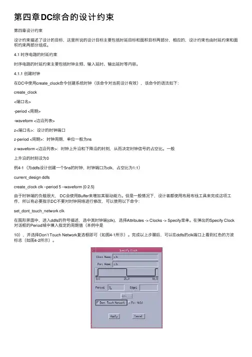
但是⼀般情况下,设计者都使⽤布局布线⼯具来完成这项⼯作,所以有必要指⽰DC不要对时钟⽹络进⾏修改,可以使⽤以下命令:set_dont_touch_network clk在图形界⾯中,进⼊ddfs的符号描述,选中其时钟端(clk),选择Attributes -> Clocks -> Specify菜单。
在弹出的Specify Clock 对话框的Period域中填⼊指定的周期值(本例中是10),并选择Don’t Touch Network复选框即可(如图4-1所⽰)。
完成以上步骤后,可以在ddfs的clk端⼝上看到红⾊的⽅波标志(如图4-2所⽰)。
(a) Specify Clock菜单 (b) 创建时钟对话框中创建时钟图4-1 在Design Analyzer4.1.2 设置输⼊延时输⼊延时的概念可⽤图4-3来解释。

散射波成像技术在地铁空洞探测中的应用李纯阳;周官群;章俊【摘要】城市地铁工程快速发展,以空洞为主的不良地质体诱发的地面塌陷事故层出不穷.传统的地震反射波法无法满足高精度探测小尺度、不均匀复杂地质体和城市施工空间受限的要求.在考虑散射波成像方法需求以及城市施工环境限制的情况,设计快速可移动城市散射波观测系统,将等效偏移距(EOM)散射成像技术应用于地铁空洞探测中,取得较好效果.%With the rapid development of city underground project , bad geological body induced by the cavity collapse accidents emerge in an endless stream.The traditional seismic reflection wave method can not to solve the high precision detection of the small scale or complex geological body and city construction space limited . The paper considering the scattering wave imaging method and city construction constraints , to design the rapid city scattering wave observation system , the equivalent offset (EOM) application of scattering imaging technology in subway hole exploration , has achieved good effect.【期刊名称】《安徽理工大学学报(自然科学版)》【年(卷),期】2018(038)003【总页数】5页(P40-44)【关键词】地铁;空洞;共散射点道集;偏移成像;散射波技术【作者】李纯阳;周官群;章俊【作者单位】安徽惠洲地质安全研究院股份有限公司研发部,安徽合肥 231202;安徽惠洲地质安全研究院股份有限公司研发部,安徽合肥 231202;中国矿业大学深部岩土力学与地下工程国家重点实验室,江苏徐州 221008【正文语种】中文【中图分类】P613截至2015 年末,中国大陆地区共26座城市开通运营城轨交通,共计116 条线路,其中地下线占总运营里程的57.8%[1]。

什么是IDM?(Fabless, Chipless, Fab-lite) (第一部分已包括)Integrated Design and Manufacture指从设计,制造,封装测试到销售自有品牌IC都一手包办的半导体垂直整合型公司..Intel,TI,Motorola,Samsung,SL等就是知名的IDM.半导体这条食物链主要分前段design,后端制造,封装测试,最后投向消费市场.有的公司只做design这块,是没有fab的,通常就叫做fabless。
有的公司,只做代工,只有fab,不做design这块,人称foundry。
那还有的公司就是从头到尾都作,这种就是IDM(Integrated Design and Manufacture)公司了。
chipless(无芯片的芯片企业)如同英国的ARM公司既不生产芯片也不销售芯片,只出售芯片中的IP授权,这样一种别具一格的“Chipless模式”。
fab-lite轻晶圆厂,介于Fabless和IDM之间。
Foundry, Fab概念与关系。
(第一部分已包括)Fab各个芯片制造公司的制造工厂,如Sl有fab1、fab2等。
foundry只做代工,只有fab,不做design这块。
可以说foundry的概念比fab大。
但现在已在逐渐的混淆。
为什么一套Mask那么贵?为什么采用MPW可以省钱?而为什么量产时又不使用MPW的Mask?(第一部分已包括)MPW多项目晶圆(Multi Project Wafer),就是将多个具有相同工艺的集成电路设计放在同一晶圆片上流片,流片后,每个设计品种可以得到数十片芯片样品,这一数量对于设计开发阶段的实验、测试已经足够。
而实验费用就由所有参加MPW的项目按照芯片面积分摊,实际成本仅为原来的5%-10%。
Wafer and die, 制造cost的构成成份?分析例:原三层金属设计,改成二层金属,die面积大5%,那么总的来讲单片cost会如何变化?(第一部分已包括)以硅工艺为例,一般把整片的硅片叫做wafer,通过工艺流程后每一个单元会被划片,封装。

关于序列二次规划(SQP)算法求解非线性规划问题研究兰州大学硕士学位论文关于序列二次规划(SQP)算法求解非线性规划问题的研究姓名:石国春申请学位级别:硕士专业:数学、运筹学与控制论指导教师:王海明20090602兰州大学2009届硕士学位论文摘要非线性约束优化问题是最一般形式的非线性规划NLP问题,近年来,人们通过对它的研究,提出了解决此类问题的许多方法,如罚函数法,可行方向法,Quadratic及序列二次规划SequentialProgramming简写为SOP方法。
本文主要研究用序列二次规划SOP算法求解不等式约束的非线性规划问题。
SOP算法求解非线性约束优化问题主要通过求解一系列二次规划子问题来实现。
本文基于对大规模约束优化问题的讨论,研究了积极约束集上的SOP 算法。
我们在约束优化问题的s一积极约束集上构造一个二次规划子问题,通过对该二次规划子问题求解,获得一个搜索方向。
利用一般的价值罚函数进行线搜索,得到改进的迭代点。
本文证明了这个算法在一定的条件下是全局收敛的。
关键字:非线性规划,序列二次规划,积极约束集Hl兰州人学2009届硕二t学位论文AbstractNonlinearconstrainedarethemostinoptimizationproblemsgenericsubjectsmathematicalnewmethodsareachievedtosolveprogramming.Recently,Manyasdirectionit,suchfunction,feasiblemethod,sequentialquadraticpenaltyprogramming??forconstrainedInthisthemethodspaper,westudysolvinginequalityabyprogrammingalgorithm.optimizationproblemssequentialquadraticmethodaofSQPgeneratesquadraticprogrammingQPsequencemotivationforthisworkisfromtheofsubproblems.OuroriginatedapplicationsinanactivesetSQPandSQPsolvinglarge-scaleproblems.wepresentstudyforconstrainedestablishontheQPalgorithminequalityoptimization.wesubproblemsactivesetofthesearchdirectionisachievedQPoriginalproblem.AbysolvingandExactfunctionsaslinesearchfunctionsubproblems.wepresentgeneralpenaltyunderobtainabetteriterate.theofourisestablishedglobalconvergencealgorithmsuitableconditions.Keywords:nonlinearprogramming,sequentialquadraticprogrammingalgorithm,activesetlv兰州大学2009届硕士学位论文原创性声明本人郑重声明:本人所呈交的学位论文,是在导师的指导下独立进行研究所取得的成果。

第24卷第3期半 导 体 学 报Vol.24,No.3 2003年3月CHIN ESE JOURNAL OF SEMICONDUCTORSMar.,2003谢晓锋 男,1975年出生,博士研究生,当前主要研究半导体器件综合的设计和实现.张文俊 男,讲师,当前主要研究半导体器件与工艺建模和模拟.杨之廉 男,教授,博士生导师,当前主要研究半导体TCAD 系统.2002204206收到,2002208208定稿○c 2003中国电子学会半导体器件建模与优化系统谢晓锋 鲁 勇 李 钊 阮 骏 姚 依 张文俊 杨之廉(清华大学微电子学研究所,北京 100084)摘要:随着器件尺寸的缩小,器件特性空间变得越来越复杂.如果仍采用手工参数调整的方法,不仅需要有较好的器件物理知识,而且也不一定能得到合适的结果.为节约设计时间,对半导体器件建模与优化系统(MOSSED )进行了研究与实现.该系统可以对半导体器件进行有效地建模、优化和综合,以得到所需要的器件.通过一些实例对部分功能进行了说明,并和一些已有的系统进行了比较.关键词:响应表面方法;实验设计;遗传算法;微粒群优化EEACC :2570A ;1180中图分类号:TN405 文献标识码:A 文章编号:025324177(2003)03203272051 引言半导体器件设计极大地受益于模拟和模型的使用,从中节省开发新的或扩展现有技术的时间与费用.但技术发展需要的远不止是一种基本的模拟能力,相反,用于帮助实现和优化设计的建模与优化工具和方法变得越来越重要了[1~3].M IT 和TI 公司合作完成的Do E/Opt 系统[1]、维也纳理工大学的V ISTA 系统[2]等,均提供了友好的图形用户界面,并结合优化算法和实验设计(design of experience ,Do E )/响应表面法(response surface methodology ,RSM )进行优化.近年来研究较多的深亚微米器件的反向建模,如SIESTA [3],也是基于将器件模拟器和优化算法结合进行器件优化.然而这些系统,有的只是一个原型系统,并不具备集成式TCAD 开发环境的功能;有的系统采用的优化算法和模拟器比较单一,且对具体细节还缺少深入地考虑.鉴于此,从1998年开始,清华大学微电子所与Motorola 公司合作,以期实现半导体工艺/器件的整体综合流程.而半导体器件建模与优化系统[4~9](modeling &optimization system for semiconductor devices ,MOSSED )是其中的一个部分.本文首先描述MOSSED 的体系结构与具体构造,然后讨论它的一些应用,并和已有的系统进行比较.2 MOSSED 介绍通过这些年的研究,我们认识到一个成功的TCAD 框架结构必须具备如下一些要素:(1)稳定性:因为一次优化通常要运行很长时间;(2)局域网的并行模拟[4]:须考虑软硬件的错误;(3)可扩展性[1~4]:必须处理不同的程序、数据格式和它们的组合;(4)器件参数化与参数链接[5]:设计空间通过器件参数化得到,这个需要已经在一些较新的TCAD 软件,如GEN ESISe [10]中实现;(5)全局优化能力[6,7]:尤其是器件响应空间随着器件缩小变得非线性化时;(6)嵌入已有知识[8]:嵌入目标和参数之间的已知关系可以大大地减少搜索时间.图1给出了MOSSED 的体系结构.基于图形界面,用户可以控制各种计算组件,包括模拟、优化以及实验设计和响应表面模型等的组合执行.而并行调度器被用来进行局域网的并行计算.计算组件是MOSSED 计算的核心部分,主要组件如图2所示.每个组件可视为一个黑盒,它有输入和输出信号.通过运行管理器,不同类型的计算组件可以交流信号,从而实现不同的功能.Model 类通过设计参数组(designable )得到响应(response ),即器件特性.主要包括需要调用如PISCES [11]、GEN ESISe 等外部TCAD 模拟器的模型接口,RSM 模型以及其它一些嵌入的解析模型.图1 MOSSED 体系结构Fig.1 Architecture of MOSSED图2 计算组件一览Fig.2 Overview for computational componentsAnalyzer 类通过设计参数和设计空间进行数据的分析和处理.主要包括:(1)优化器,其中有基于群体的全局优化器如遗传算法(genetic algorithm ,G A[6])、基于耗散结构的微粒群优化(dissipativeparticle swarm optimization ,DPSO [7])、以及局部优化器如修正阻尼最小二乘法(MDL S )等;(2)灵敏度分析;(3)评价器,对一组设计点进行评价以建模,目前嵌入了RSM 评价器.Do E 类在设计空间中产生设计参数组,主要有全因子设计、拉丁方取样(L HS )设计等.运行数据库用来有选择的保存计算结果.而参数和目标之间一些已知的单调关系也会被嵌入[8],这可以更好地了解设计空间.引导优化算法能够被引导在有希望的区域进行.典型的计算组件的组合方式如图3所示.一种是较为简单的情形,可利用RSM 评价器根据Do E 结果产生RSM 模型,并替换较为耗时的TCAD 模拟器,如过程①;但对于搜索空间高度非线性而且参数维数较高的情形,RSM 模型不够准确,从而需要由全局优化器直接调用TCAD 模拟器进行优化设计,如过程②.采用组合方式可以使得加入新的功能更为灵活.图3 实现器件优化的计算组件组合方式Fig.3 Combination methods of computational compo 2nents for realizing device optimization3 应用实例与分析我们利用一种新型聚焦离子束(focused 2ion 2beam ,FIB )MOS 进行综合[4],器件的参数化如图4所示.如果注入为一次,则称为SFIBMOS ;如果注入为两次,即包括Peak2,则称为DFIBMOS.图4 FIBMOS 器件参数化Fig.4 Parameterization of FIBMOS device3.1 “可接受区”搜索在Hosack 的工艺综合流程[12],需得到符合对器件响应约束的“可接受区”.为此设计边界和区域823半 导 体 学 报24卷 两种综合方式,对L eff =0158μm 的SFIBMOS 采用G A 调用PICSES 进行了综合[5].划分三个子任务:(1)I on =112×10-4±1%A/μm ,满足I off ≤10-12A/μm ,R out ≥8×10⁴Ω;(2)I on =115×10-4±1%A/μm ,满足I off ≤1×10-12A/μm ,R out ≥8×10⁴Ω;(3)I off =1×10-12±1%A/μm ,满足I on ∈[112×10-4,115×10-4]A/μm ,R out ≥8×10⁴Ω.每个子任务负责优化搜索“可接受区”的一条可能边界.每个子任务约需要520次PICSES 模拟.图5给出了边界综合的结果;图6给出了区域综合的结果,利用得到的可行设计点组成“准可行设计空间”.图5 边界综合的“可接受区”结果Fig.5 “Acceptability region ”by boundarysynthesis图6 区域综合的“可接受区”结果Fig.6 “Acceptability region ”by regional synthesis我们还研究了将实数设计空间根据参数的工艺精度影响转换为整型空间,并加入适应性复合算子,对于器件设计中常见的“约束满足”问题,能有效的提高对可行设计空间的覆盖率[9],获得较大的设计余量.3.2 器件建模响应表面方法可以建立数学模型来“廉价”的模拟非常耗时的器件模拟器.可以用来了解参数变化趋势、特性预测,在响应空间非线性程度较低时,甚至可以利用它来寻找可行区间.图7给出了对一个L eff =0135μm 的SFIBMOS 的I on 和G out 的响应表面与模拟结果的对比.其中设计空间Dose ∈[1×1012,2×1013]/cm -2,N sub ∈[5×1016,1×1018]/cm -3.首先采用全因子Do E 进行了52次PISCES 模拟,然后调用RSM evaluator 建立RSM 模型.图8给出了RSM 模型对数结果的等值线,其中实线为I on ,虚线为G out .两条线并不平行,说明器件是可以优化的.图9给出了利用图8结果在lg I on =-317(即I on =2×10⁻⁴A/μm )时优化G out 得到的结果,其中实线为优化后的结果,虚线为优化前的结果.图7 RSM 和模拟结果的比较 L eff =0135μm Fig.7 Comparison for RSM and simulation results L eff=0135μm 923 3期谢晓锋等: 半导体器件建模与优化系统图8 RSM模型对数等值线 实线:I on,虚线:G out Fig.8 Logarithmic isolines by RSM model Solid:I on,dashed:G out图9 利用RSM模型得到的优化结果(小的G out) Fig.9 Optimized result by using RSM model for smallG out3.3 器件优化在大部分情况下,需要得到对一些器件响应进行约束下的某些响应的优化.在设计空间较为简单(如维数低,非线性程度低)时,可以利用RSM建模直接处理,或者在RSM模型的基础上进行优化.当然,在很多时候,尤其是器件进入深亚微米后,响应空间相当复杂,而设计维数也很难降低,加上数值模拟器本身由于网格设置等因素带来的波动,全局优化能力变得至关重要.为此MOSSED中嵌入了G A(GENOCOP)[13],差异演化(differential evolution,DE)[14],并开发了DPSO[7]等全局优化算法.其中DPSO模拟自组织的耗散结构[15],对多峰函数的数值优化效果很好[7].图10给出了几种全局优化算法对一个0125μm沟长的DFIBMOS的I on在一定约束条件下最大化的优化结果比较.纵坐标表示当前优化解F c接近最优解F opt的程度,横坐标为优化代数.表1为器件的设计参数空间,而表2为优化目标.图10 几种全局优化算法的结果比较Fig.10 Performance comparison for different globaloptimization algorithms表1 DFIBMOS设计空间Table1 Design space of DFIBMOSParameter Min MaxσFIB2X1/μm0.000.25 2.5×10⁻⁴Dose1/cm-21×10101×10131×1010FIB2X2/μm0.000.25 2.5×10⁻⁴Dose2/cm-21×10101×10131×1010N sub/cm-31×10151×10181×1015表2 DFIBMOS优化目标Table2 Optimization objectives of DFIBMOSParameter ObjectiveI on/(A・μm-1)最大化I off/(A・μm-1)≤1×10-14G out/S≤1×10-54 结论本文讨论了半导体器件建模与优化系统MOSSED的原理和构成,及一部分应用方式.表3给出了MOSSED和已有的TCAD系统的比较.表3 MOSSED和已有TCAD系统的比较Table3 Comparison with existing TCAD systems名称VISTA Do E/Opt SIESTA MOSSEDGU I有有有有Do E/RSM有有无有局部优化有有有有全局优化无无无有并行计算有无有有器件知识无无无嵌入本系统在全局优化方面的优势可以提高处理复杂设计空间的能力.而同时具有的RSM技术和局部优化能力可以使得系统能适用于从简单到复杂的033半 导 体 学 报24卷 各种情形.器件知识的嵌入可以加快搜索速度,而并行处理能力可以减轻全局优化算法在计算速度方面的劣势.当然,要达到更为有效的建模与优化,合理的选择技术非常重要,否则也会导致计算效率低下,甚至无法得到结果.在今后的研究中,需要进一步利用专家的一些模糊经验,构建一个更高层次的模糊决策器以根据问题和资源合理地选择所需要的技术,使得本系统的处理能力更优.参考文献[1] Boning D S ,Mozumder P K.Do E/Opt :a system for design of ex 2periments ,response surface modeling ,and optimization using pro 2cess and device simulation.IEEE Trans Semicond Manuf ,1994,7:233[2] Plasun R ,Stockinger M ,Selberherr S.Integrated optimizationcapabilities in the VISTA technology CAD framework.IEEE CAD ,1998,17(12):1244[3] Strasser R ,Plasun R ,Selberherr S.Practical inverse modelingwith SIESTA.SISPAD ,1999:91[4] Li Z ,Xie X F ,Zhang W J ,et al.Realization of semiconductor de 2vice synthesis with the parallel genetic and South Pacific Design Automation Conference ,2001:45[5] Xie X F ,Li Z ,Ruan J ,et al.Realization of device synthesis withthe genetic algorithms.Chinese Journal of Semiconductors ,2002,23(1):95(in Chinese )[谢晓锋,李钊,阮骏,等.应用遗传算法实现MOS 器件综合.半导体学报,2002,23(1):95][6] Xie X F ,Zhang W J ,Yang Z L.A parents selection strategyfighting premature convergence in floating genetic algorithm.Control and Decision ,2002,17(5):625(in Chinese )[谢晓锋,张文俊,杨之廉.一种防止浮点遗传算法早熟收敛的父代选择策略.控制与决策,2002:17(5):625][7] Xie X F ,Zhang W J ,Yang Z L.A dissipative particle swarm opti 2mization.IEEE Congress on Evolutionary Computation ,2002:1456[8] Xie X F ,Zhang W J ,Yang Z L.Incorporating knowledge ingenetic algorithms for device synthesis.Int Conf on Solid 2State and Integrated Circuit Technology ,2001:1143[9] Xie X F ,Zhang W J ,Yang Z L.Improved genetic algorithm forsemiconductor device synthesis system.Acta Electronica Sinica ,2002,30(2):173[谢晓锋,张文俊,杨之廉.改进的用于半导体器件综合系统的遗传算法.电子学报,2002,30(2):173][10] ISE TCAD Software ,Release 6.1.ISE A G ,Zurich ,2000[11] Yu Z ,Chen D ,So L ,Dutton R W.PISCES 22ET manual.Inte 2grated Circuits Laboratory ,Stanford University ,1994[12] Hosack H H ,Mozumder P K ,Pollack G P.Recent advances inprocess synthesis for semiconductor devices.IEEE Trans Elec 2tron Devices ,1998,45(3):626[13] Michalewicz Z.G enetic algorithm +data structures =evolu 2tion programs.Springer 2Verlag ,1994[14] Storn R ,Price K.Minimizing the real functions of theICEC ’96contest by differential evolution.IEEE Int Conf on Evolutionary Computation ,1996:842[15] Nicolis G ,Prigogine I.Self 2organization in nonequilibriumsystems :from dissipative systems to order through fluctuations.New Y ork :John Wiley ,1977Modeling and Optimization System for Semiconductor DevicesXie Xiaofeng ,Lu Y ong ,Li Zhao ,Ruan J un ,Yao Y i ,Zhang Wenjun and Yang Zhilian(Instit ute of Microelect ronics ,Tsi nghua U niversity ,Beiji ng 100084,Chi na )Abstract :As device dimensions continue to be decreased ,device characteristics become more complicated.The method of adjusting pa 2rameter manually needs preferable knowledge on device physics ,and can not always get suitable results.In order to reduce design time ,the modeling and optimization system for semiconductor devices (MOSSED )is studied and im plemented.The system can perform modeling ,optimization and synthesis for semiconductor devices to achieve desired devices.S ome functions are demonstrated by some examples.At last ,the comparison to other systems is also performed.K ey w ords :response surface methodology ;design of experience ;genetic algorithm ;particle swarm optimization EEACC :2570A ;1180Article ID :025324177(2003)0320327205Xie Xiaofeng male ,was born in 1975.He is engaged in the research on design and realization of semiconductor device synthesis system.Zhang Wenjun male ,lecturer.His current research interest is in the area of semiconductor device and process modeling and simulation.Yang Zhilian professor.His current research interest is technology CAD system.Received 6April 2002,revised manuscript received 8August 2002○c 2003The Chinese Institute of Electronics133 3期谢晓锋等: 半导体器件建模与优化系统。
第29卷第12期2021年12月Vol.29No.12Dec.2021光学精密工程Optics and Precision Engineering刚性航天器的预定义时间滑模控制赛华阳1,2,徐振邦1,3*,贺帅1,张恩阳1,秦超1(1.中科院长春光学精密机械与物理研究所中科院空间光学系统在轨制造与集成重点实验室,吉林长春130033;2.中国科学院大学,北京100049;3.中国科学院大学材料与光电研究中心,北京100049)摘要:针对刚性航天器在姿态跟踪控制中存在的系统不确定及外界干扰等问题,提出了一种预定义时间滑模控制器(PTSMC)。
首先,给出了以四元数为姿态参数的航天器姿态跟踪控制系统,利用误差四元数和误差角速度设计了预定义时间滑模面。
然后,考虑了航天器系统的不确定性和外界干扰设计了一种非保守上界的PTSMC,并通过边界层技术降低了系统抖动。
最后,通过设计Lyapunov函数,证明了所提出的控制器的预定义时间稳定性和系统收敛时间上界的非保守性。
仿真结果表明,刚性航天器的姿态跟踪误差精度可达1.5×10⁻⁶rad,角速度跟踪误差精度可达2×10⁻⁶rad/s。
与现有的预定义时间控制器相比,所提出的控制器的稳定时间上限是更加非保守的,与传统PD控制和非奇异终端滑模控制相比,所提出的控制器具有更高的跟踪精度和鲁棒性。
通过3自由度气浮平台的姿态跟踪实验进一步说明了控制方案的有效性,其中角度跟踪误差小于0.1rad,位置跟踪误差小于0.2m。
关键词:航天器;姿态跟踪;预定义时间控制;滑模控制中图分类号:TP394.1;TH691.9文献标识码:A doi:10.37188/OPE.20212912.2891Predefined-time sliding mode control for rigid spacecraft SAI Hua-yang1,2,XU Zhen-bang1,3*,HE Shuai1,ZHANG En-yang1,QIN Chao1(1.CAS Key Laboratory of On-orbit Manufacturing and Integration for Space Optics System,Changchun Institute of Optics,Fine Mechanics and Physics,CAS,Changchun130033,China;2.University of Chinese Academy of Sciences,Beijing100049,China;3.Materials and Optoelectronics Research Center,University of Chinese Academy of Sciences,Beijing100049,China)*Corresponding author,E-mail:xuzhenbang@Abstract:To minimize system uncertainty and external disturbance in attitude tracking control for rigid spacecraft,a predefined-time sliding mode controller(PTSMC)is proposed.First,the spacecraft attitude tracking system is developed with quaternion parameterization,and the predefined time sliding surface is designed using an error quaternion and error angular velocity.Then,considering the uncertainties and ex⁃ternal disturbances of the spacecraft system,a PTSMC with a non conservative upper bound is designed,and the noise of the system is reduced using boundary layer technology.Finally,by designing the Lyapu⁃文章编号1004-924X(2021)12-2891-11收稿日期:2021-03-30;修订日期:2021-05-05.基金项目:国家自然科学基金项目(No.11972343,No.91848202);国家重点研发计划项目(No.2016YFE0205000)第29卷光学精密工程nov function,the predefined-time stability of the proposed controller and the non conservative upper bound of the system convergence are demonstrated.The simulation results show that using the proposed ap⁃proach,the attitude tracking accuracy of rigid spacecraft can reach1.5×10-6rad,and the angular velocity tracking accuracy can reach2×10-6rad/pared with the existing predefined time control and non singular terminal sliding mode control,the upper bound of the stabilization time of the proposed control is more non conservative and has higher tracking accuracy and robustness.The effectiveness of the control scheme is further illustrated by the attitude tracking experiment of the3DOF airborne platform.The angle tracking error is less than0.1rad,and the position tracking error is less than0.2m.Key words:spacecraft;attitude tracking;predefined-time control;sliding mode control1引言近年来,航天器的姿态跟踪问题由于在空间应用中的重要作用而得到了广泛的研究[1-2]。
CMPDesignSpaceExplorationSubjecttoPhysicalConstraintsYingminLi†,BenjaminLee‡,DavidBrooks‡,ZhigangHu††,KevinSkadron††Dept.ofComputerScience,UniversityofVirginia††IBMT.J.WatsonResearchCenter
‡DivisionofEngineeringandAppliedSciences,HarvardUniversity
{yingmin,skadron}@cs.virginia.edu,zhigangh@us.ibm.com,{dbrooks,bclee}@eecs.harvard.edu
AbstractThispaperexploresthemulti-dimensionaldesignspaceforchipmultiprocessors,exploringtheinter-relatedvari-ablesofcorecount,pipelinedepth,superscalarwidth,L2cachesize,andoperatingvoltageandfrequency,undervariousareaandthermalconstraints.Theresultsshowtheimportanceofjointoptimization.Thermalconstraintsdominateotherphysicalconstraintssuchaspin-bandwidthandpowerdelivery,demonstratingtheimportanceofcon-sideringthermalconstraintswhileoptimizingtheseotherparameters.Foraggressivecoolingsolutions,reducingpowerdensityisatleastasimportantasreducingtotalpower,whileforlow-costcoolingsolutions,reducingto-talpowerismoreimportant.Finally,thepapershowsthechallengesofaccommodatingbothCPU-boundandmemory-boundworkloadsonthesamedesign.Theirre-spectivepreferencesformorecoresandlargercachesleadtoincreasinglyirreconcilableconfigurationsasareaandotherconstraintsarerelaxed;ratherthanaccommodat-ingahappymedium,theextraresourcessimplyencouragemoreextremeoptimizationpoints.
1IntroductionRecentproductannouncementsshowatrendtowardag-gressiveintegrationofmultiplecoresonasinglechiptomaximizethroughput.However,thistrendpresentsanex-pansivedesignspaceforchiparchitects,encompassingthenumberofcoresperdie,coresizeandcomplexity(pipelinedepthandsuperscalarwidth),memoryhierarchydesign,operatingvoltageandfrequency,andsoforth.Identify-ingoptimaldesignsisespeciallydifficultbecausethevari-ablesofinterestareinter-relatedandmustbeconsideredsimultaneously.Furthermore,trade-offsamongthesede-signchoicesvarydependingbothonworkloadsandphysi-cal(e.g.,areaandthermal)constraints.Weexplorethismulti-dimensionaldesignspaceacrossarangeofpossiblechipsizesandthermalconstraints,forbothCPU-boundandmemory-boundworkloads.Fewpriorworkshaveconsideredsomanycores,andtoourknowledge,thisisthefirstworktooptimizeacrosssomanydesignvariablessimultaneously.Weshowtheinter-relatednatureoftheseparametersandhowtheoptimumchoiceofdesignparameterscanshiftdramaticallydependingonsys-temconstraints.Specifically,thispaperdemonstratesthat:•Asimple,fastapproachtosimulatealargenumberofcoresbyobservingthatcoresonlyinteractthroughtheL2cacheandsharedinterconnect.Ourmethodologyusessingle-coretracesandonlyrequiresfastcachesimulationformulti-coreresults.•CPU-andmemory-boundapplicationsdesiredramat-icallydifferentconfigurations.Adaptivityhelps,butanycompromiseincursthroughputpenalties.•Thermalconstraintsdominate,trumpingevenpin-bandwidthandpower-deliveryconstraints.Oncether-malconstraintshavebeenmet,throughputisthrottledbacksufficientlytomeetcurrentpin-bandwidthandITRSpower-deliveryconstraints.•Adesignmustbeoptimizedwiththermalconstraints.Scalingfromthethermal-blindoptimumleadstoaconfigurationthatisinferior,sometimesradicallyso,toathermallyoptimizedconfiguration.•Simpler,smallercoresarepreferredundersomecon-straints.Inthermallyconstraineddesigns,themaindeterminantisnotsimplymaximizingthenumberofcores,butmaximizingtheirpowerefficiency.Ther-malconstraintsgenerallyfavorshallowerpipelinesandlowerclockfrequencies.•Additionalcoresincreasethroughput,despitethere-sultingvoltageandfrequencyscalingrequiredtomeetthermalconstraints,untilperformancegainsfromanadditionalcoreisnegatedbytheimpactofvoltageandfrequencyscalingacrossallcores.•Foraggressivecoolingsolutions,reducingpowerden-sityisatleastasimportantasreducingtotalpower.Forlow-costcoolingsolutions,however,reducingto-talpowerismoreimportant.Thispaperisorganizedasfollows.Section2isthere-latedwork.Weintroduceourmodelinfrastructureandval-idationinsection3.Wepresentdesignspaceexplorationresultsandexplanationsinsection4.Weendwithconclu-sionsandproposalsforfutureworkinsection5.2RelatedWorkTherehasbeenaburstofworkinrecentyearstounder-standtheperformance,energy,andthermalefficiencyofdifferentCMPorganizations.Fewhavelookedatalargenumbersofcoresandnone,ofwhichweareaware,have
150-7803-9368-6/06/$20.00/©2006 IEEEjointlyoptimizedacrossthelargenumberofdesignparam-etersweconsiderwhileaddressingtheassociatedmethod-ologychallenges.LiandMart´ınez[17]presentthemostaggressivestudyofwhichweareaware,exploringupto16-wayCMPsforSPLASHbenchmarksandconsideringpowerconstraints.Theirresultsshowthatparallelexecu-tiononaCMPcanimproveenergyefficiencycomparedtothesameperformanceachievedviasingle-threadedex-ecution,andthatevenwithinthepowerbudgetofasin-glecore,aCMPallowssubstantialspeedupscomparedtosingle-threadedexecution.Kongetiraetal.[12]describetheSunNiagaraprocessor,aneight-wayCMPsupportingfourthreadspercoreandtar-getingworkloadswithhighdegreesofthread-levelparal-lelism.Chaudhryetal.[4]describethebenefitsofmultiplecoresandmultiplethreads,sharingeightcoreswithasin-gleL2cache.TheyalsodescribetheSunRockprocessor’s“scouting”mechanismthatusesahelperthreadtoprefetchinstructionsanddata.El-Moursyetal.[6]showtheadvantagesofclusteredarchitecturesandevaluateaCMPofmulti-threaded,multi-clustercoreswithsupportforuptoeightcontexts.Huhetal.[10]categorizedtheSPECbenchmarksintoCPU-bound,cache-sensitive,orbandwidth-limitedgroupsandexploredcorecomplexity,areaefficiency,andpinband-widthlimitations,concludingduetopin-bandwidthlimi-tationsthatasmallernumberofhigh-performancecoresmaximizesthroughput.EkmanandStenstrom[5]useSPLASHbenchmarkstoexploreasimilardesignspaceforenergy-efficiencywiththesameconclusions.Kumaretal.[14]considertheperformance,power,andareaimpactoftheinterconnectionnetworkinCMParchi-tecture.Theyadvocatelowdegreesofsharing,butusetransactionorientedworkloadswithhighdegreesofinter-threadsharing.Sincewearemodelingthroughput-orientedworkloadsconsistingofindependentthreads,wefollowtheexampleofNiagara[12]andemploymoreaggressiveL2sharing.Inourexperiments,eachL2cachebankissharedbyhalfthetotalnumberofcores.Interconnectiondesignparametersarenotvariableinourdesignspaceatthistime,andinfactconstituteasufficientlyexpansivedesignspaceoftheirownthatweconsiderthistobebeyondthescopeofthecurrentpaper.Theresearchpresentedinthispaperdiffersfrompriorworkinthelargenumberofdesignparametersandmetricsweconsider.WeevaluateCMPdesignsforperformance,powerefficiency,andthermalefficiencywhilevaryingthenumberofcoresperchip,pipelinedepthandwidth,chipthermalpackagingeffectiveness,chiparea,andL2cachesize.Thisevaluationisperformedwithafastdecou-pledsimulationinfrastructurethatseparatescoresimula-tionfrominterconnection/cachesimulation.Byconsider-ingmanymoreparametersinthedesignspace,wedemon-stratetheeffectivenessofthisinfrastructureandshowtheinter-relatednessoftheseparameters.ThemethodologiesforanalyzingpipelinedepthandwidthbuildonpriorworkbyLeeandBrooks[16]bydevelopingfirst-ordermodelsforcapturingchangesincoreareaaspipelinedimensionschange,therebyenablingpowerdensityandtemperatureanalysis.Weidentifyop-timalpipelinedimensionsinthecontextofCMParchi-tectures,whereasmostpriorpipelineanalysisconsiderssingle-coremicroprocessors[8,9,22],Furthermore,mostpriorworkinoptimizingpipelinesfocusedexclusivelyonperformance,althoughZyubanetal.found18FO4delaystobepower-performanceoptimalforasingle-threadedmi-croprocessor[26].Otherresearchershaveproposedsimplifiedprocessormodels,withthegoalofacceleratingsimulation.Withinthemicroprocessorcore,KarkhanisandSmith[11]de-scribeatrace-driven,first-ordermodelingapproachtoestimateIPCbyadjustinganidealIPCtoaccountforbranchmisprediction.Incontrast,ourmethodologyadjustspower,performance,andtemperatureestimatesfromde-tailedsingle-coresimulationstoaccountforfabricevents,suchascachemissesandbuscontention.Inordertomodellargescalemultiprocessorsystemsrunningcommercialworkloads,Kunkeletal.[15]utilizeanapproachthatcom-binesfunctionalsimulation,hardwaretracecollection,andprobabilisticqueuingmodels.However,ourdecoupledanditerativeapproachallowsustoaccountforeffectssuchaslatencyoverlapduetoout-of-orderexecution,effectsnoteasilycapturedbyqueuingmodels.Althoughdecoupledsimulationframeworkshavebeenproposedinthecontextofsingle-coresimulation(e.g.,KumarandDavidson[13])withargumentssimilartoourown,ourmethodologyisap-pliedinthecontextofsimulatingmulti-coreprocessors.