5-数字IO实验
- 格式:doc
- 大小:27.00 KB
- 文档页数:2
目录实验一整流、滤波、稳压电路 (1)实验二单级交流放大器(一) (5)实验三单级交流放大器(二) (7)实验四两级阻容耦合放大电路 (9)实验五负反馈放大电路 (11)实验六射极输出器的测试 (14)实验七 OCL功率放大电路 (16)实验八差动放大器 (18)实验九运算放大器的基本运算电路(一) (20)实验十集成运算放大器的基本运算电路(二) (22)实验十一比较器、方波—三角波发生器 (24)实验十二集成555电路的应用实验 (26)实验十三 RC正弦波振荡器 (30)实验十四集成功率放大器 (32)实验十五函数信号发生器(综合性实验) (34)实验十六积分与微分电路(设计性实验) (36)实验十七有源滤波器(设计性实验) (38)实验十八电压/频率转换电路(设计性实验) (40)实验十九电流/电压转换电路(设计性实验) (41)实验一整流、滤波、稳压电路一、实验目的1、比较半波整流与桥式整流的特点。
2、了解稳压电路的组成和稳压作用。
3、熟悉集成三端可调稳压器的使用。
二、实验设备1、实验箱(台)2、示波器3、数字万用表三、预习要求1、二极管半波整流和全波整流的工作原理及整流输出波形。
2、整流电路分别接电容、稳压管及稳压电路时的工作原理及输出波形。
3、熟悉三端集成稳压器的工作原理。
四、实验内容与步骤首先校准示波器。
1、半波整流与桥式整流:●分别按图1-1和图1-2接线。
●在输入端接入交流14V电压,调节使I O=50mA时,用数字万用表测出V O,同时用示波器的DC档观察输出波形记入表1-1中。
图1-1图1-2Vi(V) V O(V) I O (A) V O波形半波桥式2、加电容滤波:上述实验电路不动,在桥式整流后面加电容滤波,如图1-3接线,比较并测量接C 与不接C两种情况下的输出电压V O及输出电流I O,并用示波器DC档观测输出波形,记入表1-2中。
图1-33上述电路不动,在电容后面加稳压二极管电路(510Ω、VDz),按图1-4接线。

单片机led灯闪烁实验报告1. 实验目的:掌握单片机控制LED灯闪烁的方法,了解单片机数字输入输出端口的使用。
2. 实验材料:STM32F103C8T6开发板、杜邦线、LED灯3. 实验原理:在单片机中,数字输入输出口(IO口)是实现数字输入输出的重要接口。
在单片机中,IO口除了可以做通用输入输出口以外,还有很多专用功能口,如SPI 口、I2C口等。
单片机控制LED灯闪烁的原理就是利用IO口的输出功能,通过改变输出口的电平信号来控制LED的亮灭。
当IO口输出高电平时,控制LED为亮状态;当IO 口输出低电平时,控制LED为灭状态。
4. 实验步骤:(1)将LED灯的正极连接到单片机的GPB5号引脚(即B端口的5号引脚),将LED的负极连接到地。
(2)在Keil中新建工程,并配置IO口为输出口。
(3)编写程序,利用GPIO_WriteBit函数对GPB5号引脚进行高低电平控制,实现LED灯的闪烁。
(4)将程序下载到开发板中,观察LED灯的闪烁情况。
5. 实验代码:#include "stm32f10x.h"void Delay(uint32_t nCount) {for(; nCount != 0; nCount);}int main(void) {GPIO_InitTypeDef GPIO_InitStructure;RCC_APB2PeriphClockCmd(RCC_APB2Periph_GPIOB, ENABLE);GPIO_InitStructure.GPIO_Pin = GPIO_Pin_5;GPIO_InitStructure.GPIO_Mode = GPIO_Mode_Out_PP;GPIO_InitStructure.GPIO_Speed = GPIO_Speed_50MHz;GPIO_Init(GPIOB, &GPIO_InitStructure);while(1) {GPIO_SetBits(GPIOB, GPIO_Pin_5);Delay(0xFFFFF);GPIO_ResetBits(GPIOB, GPIO_Pin_5);Delay(0xFFFFF);}}6. 实验结果:当程序下载到开发板中时,LED灯会以一定频率闪烁。
简单io口扩展实验报告
简单IO口扩展实验报告
本次实验旨在学习如何通过简单IO口扩展模块对单片机的IO口进行扩展,实现多个IO口的输入输出功能。
我们需要了解简单IO口扩展模块的基本原理和工作方式。
简单IO 口扩展模块通过与单片机的SPI总线进行通信,实现对其内部寄存器的读写操作,从而实现对IO口的扩展。
在实验中,我们使用STM32F103C8T6开发板和简单IO口扩展模块,通过连接它们的SPI总线,可以将扩展模块的IO口与开发板的IO口进行连接,实现IO口的扩展。
具体连接方式如下图所示:
(此处省略图片)
接下来,我们需要进行程序设计。
在初始化时,需要设置SPI总线的相关参数,然后对扩展模块进行初始化,将其内部寄存器中的数据清零。
然后,通过读写寄存器的方式,可以对扩展模块的每个IO 口进行配置,设置其输入输出状态、上下拉电阻等参数。
在程序中,我们可以通过读取扩展模块的输入口状态,判断是否有外部信号输入,根据需要进行相应的操作。
例如,当输入口接收到高电平信号时,可以控制某个输出口输出高电平信号,从而实现控制设备的功能。
在实验中,我们可以通过连接LED和按键来进行简单的IO口扩展实验。
将LED连接到扩展模块的输出口,按键连接到扩展模块的输入口,通过控制按键输入信号,实现对LED的控制。
总的来说,本次实验通过学习简单IO口扩展模块的原理和工作方式,掌握了通过SPI总线进行IO口扩展的方法,实现了对单片机多个IO口的输入输出控制,为后续的硬件控制和应用开发打下了基础。

单片机原理实验报告实验一:IO开关量输入输出实验学院: 物理与机电工程学院专业: 电子科学与技术班级: 2013 级 2 班学号: 201310530208姓名: 何丽丽指导老师: 柳妮实验一IO开关量输入输出实验目的:学习单片机读取IO引脚状态的的方法。
内容:编程读取IO引脚状态。
设备:EL-EMCU-I试验箱、EXP-89S51/52/53 CPU板。
编程:首先要把相关的引脚设置在IO的输入状态,然后写一个循环,不停地检测引脚的状态。
步骤:1、将CPU板正确安放在CPU接口插座上,跳线帽JP2短接在上侧。
2、连线:用导线将试验箱上的的IO1--- IO8分别连接到SWITCH 的8个拨码开关的K1---K8的输出端子K1---K8上,连接好仿真器。
3、实验箱上电,在PC机上打开Keil C环境,打开实验程序文件夹IO_INPUT下的工程文件IO_INPUT.Uv2编译程序,上电,在程序注释处设置断点,进入调试状态,打开窗口Peripherals-->IO-Port-->P0,改变开关状态,运行程序到断点处,观察窗口的数值与开关的对应关系。
程序:ORG 0000HLJMP MAINORG 0030HMAIN:MOV P0,#0FFHMOV A,P0SWAP AMOV P0,ASJMP MAINEND程序分析:从上面的程序可以看出我们需要用导线将试验箱上的的IO1--- IO8分别连接到SWITCH的8个拨码开关的K1---K8的输出端子K1---K8上,连接好仿真器。
在通过SWAP A MOV P0,A这组指令来对P0口所接的对应的发光二极管对应的状态通过拨码开关的开关来控制发光二极管。
结论:通过上面这段程序,我们实现了用拨码开关来控制P0口所接的发光二极管的亮灭。
通过I\O口P0.0—P0.3接拨码开关,P0.4—P0.7一一对应的接发光二极管。
数字io模块数字IO模块是一种用于处理数字输入输出的设备,它在计算机系统中起到了重要的作用。
本文将介绍数字IO模块的基本原理、应用场景以及相关的技术细节。
数字IO模块是一种用于连接计算机与外部设备的接口模块,可以实现计算机与外部设备之间的数字信号传输。
它通常包括多个输入通道和输出通道,可以同时处理多个信号。
数字IO模块的输入通道用于接收外部设备传输过来的数字信号,而输出通道则可以将计算机生成的数字信号传输给外部设备。
数字IO模块的应用非常广泛,比如在工业自动化领域中,数字IO 模块可以用于控制各种工业设备的开关、传感器的采集等操作。
在科学实验中,数字IO模块可以用于采集实验数据、控制实验仪器等。
此外,数字IO模块还可以应用于机器人控制、仪器仪表等领域。
数字IO模块的工作原理是通过数字信号的高低电平来表示不同的状态。
例如,高电平可以表示逻辑1,低电平可以表示逻辑0。
数字IO模块接收到输入信号后,会将其转换为计算机可以识别的数字信号,并通过总线传输给计算机。
而计算机生成的数字信号则通过总线传输给数字IO模块,再由数字IO模块转换为对应的电信号输出给外部设备。
数字IO模块的技术细节包括输入通道和输出通道的数量、通信协议、输入输出的电平范围、数据传输速率等。
不同的数字IO模块在这些方面可能有所不同,因此在选择和使用数字IO模块时需要根据具体需求进行选型。
在使用数字IO模块时,需要编写相应的程序来控制和读取数字IO 模块的输入输出。
编程语言提供了一系列的函数和接口来实现数字IO模块的控制。
例如,在C语言中,可以使用标准库中的函数来进行数字IO模块的初始化、读取输入信号、输出信号等操作。
同时,也可以使用其他高级编程语言如Python来编写程序控制数字IO模块。
总结起来,数字IO模块是一种用于处理数字输入输出的设备,广泛应用于工业自动化、科学实验、机器人控制等领域。
它通过将外部设备的数字信号转换为计算机可以识别的信号,实现了计算机与外部设备之间的数字信号传输。
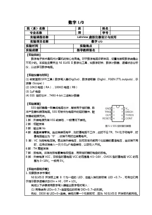
数字I/O注释数字I/O位于开发板的右侧。
(2)启动NI ELVISmx Instrument Launcher。
(3)选择数字写入器(DigOut)图标。
新的数字逻辑诊断窗口打开,用户可以设置/重置任何数字线路为HI或LO状态。
默认条件下,数字I/O的<0..7>由Linesto Writebox中的3个8位端口选择。
图5-2 Dig Out 前面板窗口Manual Pattern中的数字输出线从右至左标为0至7。
您可以通过点击顶端或虚拟开关的按钮来设置/重置(HI/LO)任意位。
这8位组成一个字节,可通过二进制、八进制或十六进制方式读取,也可以用SI符号显示在开关上面。
通过点击变灰部分,可设置显示的进制(格式)。
图5-3 LabVIEW中显示的二进制、八进制或十六进制(4)完成数字模式设置后,开启开发板电源并点击Run(绿色箭头)将模式发送至并行输出数字I/O<0..7>端,输出端LED将依次显示为绿色。
注释用户可通过设置生成方式来输出单个模式或连续输出。
在连续操作中,硬件根据当前模式连续更新。
设置的模式反映在SFP上Bus State的线路状态上(蓝色LED指示器)。
同样,通过SFP 的Action按钮可切换、循环、左右平移位模式。
(5)按下Stop按钮(红色)可终止端口更新。
在测试数字电路中,可选择数种常用的模式用于诊断检查。
(6)点击SFP上的Pattern选择器可浏览可用的选项。
手动载入任意8位格式:斜坡(0-255) 计算机指令INC交替1/0 计算机指令INVERT步长1s 计算机指令SHIFT LEFT LOGIC(7)尝试输出每一个位模式。
(8)关闭数字写入器窗口。
2.555数字时钟电路可以配置555定时芯片,配合电阻R A,R B,电容C(1µF),实现数字时钟源。
按照以下步骤搭建555数字时钟电路,并完成测量:(1)使用DMM[Ω] and DMM[ ],测量元器件值,并填写下表。

单片机实习心得单片机实习心得1很多人说,学单片机最好先学汇编语言,以我的经验告诉大家,绝对没有这个必要,初学者一开始就直接用C语言为单片机编程,既省时间,学起来又容易,提高速度会很快。
在刚开始学单片机的时候,千万不要为了解单片机内部结构而浪费时间,这样只能打击你的信心,当你学会编程后,自然一步步就掌握其内部结构了。
单片机的学习实践。
单片机提高重在实践,想要学好单片机,软件编程必不可少。
可是熟悉硬件对于学好单片机的也是十分重要的。
如何学习好硬件,动手实践是必不可少的。
我们能够经过自我动手做一个自我的电子制作,经过完成它,以提高我的对一些芯片的了解和熟练运用它。
这样我们就能够多一些了解芯片的结构。
我相信,你完成了一个属于自我的电子制作,你的单片机水平就会有一个质的提高。
这就是我学习单片机的心得体会,期望给单片机的爱好者学好单片机有所帮忙。
使用单片机就是理解单片机硬件结构,以及内部资源的应用,在汇编或C语言中学会各种功能的初始化设置,以及实现各种功能的程序编制。
第一步:数字IO的使用使用按钮输入信号,发光二极管显示输出电平,就能够学习引脚的数字IO功能,在按下某个按钮后,某发光二极管发亮,这就是数字电路中组合逻辑的功能,虽然很简单,可是能够学习一般的单片机编程思想,例如,必须设置很多寄存器对引脚进行初始化处理,才能使引脚具备有数字输入和输出输出功能。
每使用单片机的`一个功能,就要对控制该功能的寄存器进行设置,这就是单片机编程的特点,千万不要怕麻烦,所有的单片机都是这样。
第二步:定时器的使用学会定时器的使用,就能够用单片机实现时序电路,时序电路的功能是强大的,在工业、家用电气设备的控制中有很多应用,例如,能够用单片机实现一个具有一个按钮的楼道灯开关,该开关在按钮按下一次后,灯亮3分钟后自动灭,当按钮连续按下两次后,灯常亮不灭,当按钮按下时间超过2s,则灯灭。
数字集成电路能够实现时序电路,可编程逻辑器件(PLD)能够实现时序电路,可编程控制器(PLC)也能够实现时序电路,可是仅有单片机实现起来最简单,成本最低。
实验5 负反馈放大电路的分析实验原理反馈是将输出信号的部分或全部通过反向传输网络引回到电路的输入端,与输入信号叠加后作用于基本放大电路的输入端。
当反馈信号与输入信号相位相反时,引入的反馈信号将抵消部分输入信号,这种情况称为负反馈。
在基本放大系统中引入负反馈可以提高放大器的性能,具有稳定电路的作用,但这是以牺牲放大器的增益为代价。
负反馈对放大器性能指标的影响取决于反馈组态和反馈深度的大小。
负反馈系统组态根据反馈信号的取样的种类可以分为电压反馈和电流反馈,根据反馈信号与输入信号的叠加关系何以分为串联反馈和并联反馈。
综合这两方面,就有了负反馈电路的四种组态即电压串联负反馈、电流串联负反馈、电压并联负反馈、电流并联负反馈。
负反馈系统特性1、系统增益及其稳定性A f=A1+AF∆A f A f=11+AF×∆A A可见负反馈放大器的增益下降了(1+AF)倍,但其稳定性却提高了(1+AF)倍。
当闭环系统满足深度负反馈条件(即AF≫1)时,系统增益A f就与基本放大器的开环增益无关,而仅由反馈系数F决定,即A f≈1/F。
2、输入电阻对于串联负反馈R if=(1+AF)R i可见串联负反馈使放大器的输入电阻提高了(1+AF)倍对于并联负反馈R if=1(1+AF)R i可见并联负反馈使放大器的输入电阻下降了(1+AF)倍3、输出电阻对于电压负反馈R of=1(1+AF)R o可见电压负反馈使放大器的输出电阻下降了(1+AF)倍,系统更加接近理想电压源。
对于电流负反馈R of=(1+AF)R o可见电流负反馈使放大器的输出电阻提高了(1+AF)倍,系统更加接近理想电流源。
4、通频带负反馈能够展宽放大器的通频带宽,对于但极点心系统,电路的增益带宽积为常数。
对于多极点系统,系统的增益带宽积不再是常数,但通频带总有所扩展。
f Lf=f L1+AF f Hf=(1+AF)f HB f=f Hf−f Lf≈(1+AF)B5、非线性失真负反馈能够减小放大器的非线性失真。
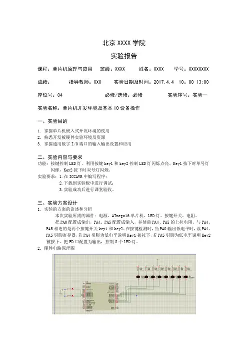
北京XXXX学院实验报告课程:单片机原理与应用班级:XXXX 姓名:XXXX 学号:XXXXXXXX 成绩:指导教师:XXX 实验日期及时间:2017.4.4 10:00-13:00 座位号:04 必修/选修:必修实验序号:实验一实验名称:单片机开发环境及基本IO设备操作一、实验目的1.掌握单片机嵌入式开发环境的使用2.熟悉开发板硬件实验环境及资源3.掌握通用数字I/O端口的输入输出设置和应用二、实验内容与要求功能:按键控制LED灯。
利用按键key1和key2控制LED灯闪烁点亮。
Key1按下时单号灯闪烁,Key2按下时双号灯闪烁。
实验要求:1.在ICCAVR中编写程序;2.下载到实验板中进行调试;3.实验成功后进行课堂验收。
三、实验方案设计1. 实验的方案的论述和分析本次实验所需的器件:电源、ATmega16单片机、LED灯、按键开关、电阻。
把PA0配置成输出,PA4、PA5配置成输入,并使能PA4、PA5的上拉电阻。
与PA4、PA5相连的是两个按键开关key1和key2。
在按键检测时,当PA0输出低电平时,读PA4、PA5引脚寄存器,若PA4引脚为低电平说明Key1被按下,若PA5引脚为低电平说明Key2被按下。
把PD口配置为输出,控制8个LED灯。
2.硬件电路原理图2.软件流程图、重要数据结构、重要控制参数设计等(1)软件流程图:(2)重要数据结构及重要控制参数设计:初始化配置:DDRA配置为0X0f,PA0为输出。
PA4、PA5配置成输入,并使能PA4、PA5的上拉电阻。
按键扫描部分:通过PINA和0B00110000的按位读取PA4和PA5口是否按下。
当PA4按下时key_value==2,当PA5按下时key_value==1,并分别执行相应语句。
四、实验结果Key1按下时单号灯闪烁Key2被按下时双号灯闪烁五、实验分析及体会1.实验过程中遇到的主要问题、(拟)解决方法。
由于是第一次做单片机实验,对实验过程和代码编写不是很熟悉。

学院:信息与电气工程学院班级:电信081 姓名:学号:课程:DSP原理及应用实验日期:_____年月日成绩:实验一开发环境建立一、实验目的(1) 学会CCS软件的安装方法。
(2) 熟悉CCS集成开发环境,掌握工程的生成方法。
(3) 熟悉CCS常用菜单的使用。
(4) 掌握CCS集成开发环境的调试方法。
二、实验原理CCS是进行DSP开发的一个集成环境,它是在 WINDOWS系统下工作的一个软件,通过该软件,我们可以进行DSP程序及系统的开发。
CCS提供了配置、建立、调试、跟踪和分析程序的工具,是进行DSP开发的常用工具,它是在WINDOWS系统下工作的一个软件,通过该软件,我们可以进行DSP程序的编辑及系统的开发。
3. 实验仪器和设备(1) 主机1台(2) 仿真器1台(3) 主机1台三、实验内容及步骤3.1 CCS 安装双击Code Composer Studio 图标;按照光标与提示依次执行,最后安装完成后重启计算机。
3.2 SEED-XDS510PLUS 的驱动安装1、将SEED-XDS510PLUS 仿真器的USB 插头插入PC 机的USB 插槽中,启动计算机后识别SEED-XDS510PLUS 硬件,识别后安装其驱动程序。
2.按照提示依次执行,同时默认路径为CCS 的安装路径。
3.安装完毕后打开控制面板查看系统中的设备管理器,出现如下结果,证明硬件连接成功。
学院:信息与电气工程学院班级:电信081 姓名:学号:课程:DSP原理及应用实验日期:_____年月日成绩:4.将仿真器JTAG 插头与实验箱主控板SEED-DEC6713 的JTAG 插头J1 相连,打开实验箱电源开关。
观察SEED-DTK_MBoard 单元的+5V、+3.3V、+15V、-15V 的电源指示灯以及SEED-DEC6713 的D2 与D4 的电源指示灯均亮。
5.双击usb20rest.exe,如下图。
可以对仿真器进行复位:3.3 驱动程序的配置1.双击桌面上的Setup CCS 2(6000)。
关于利用arduino开发板制作智能花盆的研究报告开心农场,也称“凤耕园”是我们学校的综合实践劳动基地,我们观察、认识、记录校园种植的农作物的同时,老师还会要求我们按时令种植一种蔬菜,并观察其成长过程,获得相应的劳动技能的同时,大大增强我们热爱生活、热爱自然、热爱生命的积极性。
每当寒暑假,我们有的同学要回外省老家,担心放在家里的植物没人照顾,要把菜苗带回老家,很是麻烦。
学习了arduino的美思齐编程后,我们兴趣小组进行花盆自动浇水的研究,研究的方式是理论+实验不断尝试,现将研究过程展示如下:一、小组成员XX 五年级XXX 五年级XXX 三年级二、研究过程网上购买湿度传感器及水泵后,在老师的指导下,我们先做的土壤湿度检测试验:将湿度传感器(通过LM393)接到arduino板上。
1、VCC接电源正极3.3-5V2、A0 接ARDUINO A13、D0 接ARDUINO D14、GND接电源负极上传代码如下:通过串口监视器,我们直观测到了当前传感器的湿度值在1000左右。
第二步,接水泵试机。
老师故意引导我们做了一个失败的试验。
我和小伙伴们将水泵正极接ARDUINO A6脚,负极接GND。
然后上传程序,用电脑USB给ARDUINO供电。
结果无论我们将温度值改多少,水泵都不抽水。
后来老师告诉我们水泵必须另供电,并问我们小电流控制大电流必须用到什么元件?于是有了第三步,加接继电器,并重新设计接线及代码,老师给我们提供一个手机通电宝给水泵供电。
需要说明的是,水泵的红线接继电器常开,电源正极继电器公共端,黑线和电源负极接到一起,我们弄了半天才理解。
实验第四步,添加显示屏有小伙伴提出能不能用显示屏显示当前的温湿度呢?我们也进行了尝试:发现完全可以实现。
需要指出的是要用到以下库(COPY到LIB目录里)DHTlib 和LiquidCrystal_I2C,否则编译不过关。
实验第五步,通过简单的继电器控制水泵的开关的研究,到温湿度在LED1602上显示,到用湿度传感器输入值来控制水泵的开与关。
东南大学《微机实验及课程设计》实验报告实验五8253 计数器/定时器实验六8255 并行输入输出姓名:学号:08011专业:自动化实验室:计算机硬件技术实验时间:2012年04月27日报告时间:2013年05月15日评定成绩:审阅教师:一. 实验目的实验五:1)掌握计数器/定时器8253 的基本工作原理和编程应用方法;2)了解掌握8253 的计数器/定时器典型应用方法实验六:1)掌握8255方式0的工作原理及使用方法,利用直接输入输出进行控制显示;2)掌握8段数码管的动态刷新显示控制;3)分析掌握8255工作方式1时的使用及编程,进一步掌握中断处理程序的编写。
二. 实验内容实验五:必做:5-1 将计数器0设置为方式0,计数初值为N(小于等于0FH),用手动的方式逐个输入单脉冲,编程使计数值在屏幕上显示,并同时用逻辑笔观察OUT0电平变化。
(参考程序p63)5-2 将计数器0、1分别设置在方式3,计数初值设为1000,用逻辑笔观察OUT0电平的变化。
(参考程序p64)实验六:(1)8255方式 0:简单输入输出实验电路如图一,8255C口输入接逻辑电平开关K0~K7,编程A口输出接 LED显示电路L0~L7;用指令从 C口输入数据,再从A口输出。
图一 8255简单输入输出(2)编程将A口 L0-L7控制成流水灯,流水间隔时间由软件产生;流水方向由K0键在线控制,随时可切换;流水间隔时间也可由K4~K7键编码控制,如 0000对应停止,0001对应 1秒,1111对应 15秒,大键盘输入 ESC键退出。
(3)8段数码管静态显示:按图二连接好电路,将 8255的 A口PA0~PA6分别与七段数码管的段码驱动输入端a~g相连,位码驱动输入端 S1接+5V(选中),S0、dp接地(关闭)。
编程从键盘输入一位十进制数字(0~9),在七段数码管上显示出来。
图二单管静态显示(4) 8段数码管动态显示:按图三连接好电路,七段数码管段码连接不变,位码驱动输入端S1、S0 接8255 C口的PC1、PC0。
Whitepapers 1.0Red Hat EnterpriseLinux 5 IO Tuning GuidePerformance Tuning Whitepaper for Red Hat Enterprise Linux 5.2Red Hat Inc.Don DomingoAbstractThe Red Hat Enterprise Linux 5 I/O Tuning Guide presents the basic principles ofperformance analysis and tuning for the I/O subsystem. This document also providestechniques for troubleshooting performance issues for the I/O subsystem.1. Preface (2)1.1. Audience (2)1.2. Document Conventions (3)1.3. Feedback (4)2. The I/O Subsystem (4)3. Schedulers / Elevators (5)4. Selecting a Scheduler (6)5. Tuning a Scheduler and Device Request Queue Parameters (6)5.1. Request Queue Parameters (7)6. Scheduler Types (7)6.1. cfq Scheduler (7)6.2. deadline Scheduler (8)6.3. anticipatory Scheduler (9)6.4. noop Scheduler (10)Index 10 A. Revision History 11Red Hat Enterprise Linux 5 IO Tuning Guide1. PrefaceThis guide describes how to analyze and appropriately tune the I/O performance of your Red Hat Enterprise Linux 5 system.ScopeThis guide discusses the following major topics:•Investigating system performance•Analyzing system performance•Red Hat Enterprise Linux 5 performance tuning•Optimizing applications for Red Hat Enterprise Linux 5The scope of this document does not extend to the investigation and administration of faulty system components. Faulty system components account for many percieved performance issues; however, this document only discusses performance tuning for fully functional systems.1.1. AudienceDue to the deeply technical nature of this guide, it is intended primarily for the following audiences. Senior System AdministratorsThis refers to administrators who have completed the following courses / certifications:•RH401 - Red Hat Enterprise Deployment, Virtualization and Systems Management; for more information, refer to https:///1training/1rhce/1courses/1rh401.html•RH442 - Red Hat Enterprise System Monitoring and Performance Tuning; for more information, refer to https:///1training/1architect/1courses/1rh442.html•RHCE - Red Hat Certified Engineers, or administrators who have completedRH300 (Red Hat Rapid Track Course); for more information, refer tohttps:///1training/1rhce/1courses/1rh300.htmlApplication DevelopersThis guide also contains several sections on how to properly tune applications to make them more resource-efficient.Document Conventions 1.2. Document ConventionsCertain words in this manual are represented in different fonts, styles, and weights. This highlighting indicates that the word is part of a specific category. The categories include the following:Courier fontCourier font represents commands, file names and paths, and prompts.When shown as below, it indicates computer output:Desktop about.html logs paulwesterberg.pngMail backupfiles mail reportsbold Courier fontBold Courier font represents text that you are to type, such as: xload -scale 2italic Courier fontItalic Courier font represents a variable, such as an installation directory: install_dir/bin/ bold fontBold font represents application programs, a button on a graphical application interface (OK), or text found on a graphical interface.Additionally, the manual uses different strategies to draw your attention to pieces of information. In order of how critical the information is to you, these items are marked as follows:Red Hat Enterprise Linux 5 IO Tuning Guide1.3. FeedbackIf you have thought of a way to make this manual better, submit a bug report through the followingBugzilla link: File a bug against this book through Bugzilla1File the bug against Product: Red Hat Enterprise Linux, Version: rhel5-rc1. The Component shouldbe Performance_Tuning_Guide.Be as specific as possible when describing the location of any revision you feel is warranted. If youhave located an error, please include the section number and some of the surrounding text so we canfind it easily.2. The I/O SubsystemThe I/O subsystem is a series of processes responsible for moving blocks of data between disk andmemory. In general, each task performed by either kernel or user consists of a utility performing any ofthe following (or combination thereof):•Reading a block of data from disk, moving it to memory•Writing a new block of data from memory to diskRead or write requests are transformed into block device requests that go into a queue. The I/Osubsystem then batches similar requests that come within a specific time window and processes themall at once. Block device requests are batched together (into an “extended block device request”)when they meet the following criteria:•They are the same type of operation (read or write).•They belong to the same block device (i.e. Read from the same block device, or are written to thesame block device.•Each block device has a set maximum number of sectors allowed per request. As such, theextended block device request should not exceed this limit in order for the merge to occur.•The block device requests to be merged immediately follow or precede each other.Read requests are crucial to system performance because a process cannot commence unless itsread request is serviced. This latency directly affects a user's perception of how fast a process takes tofinish.1 https:///enter_bug.cgi?product=Red%20Hat%20Enterprise%20Linux%205&bug_status=NEW&version=5.2&component=Performance_Tuning_Guide&rep_platform=All&op_sys=Linux&priority=low&bug_severity=low&assign %3A%2F%2F&short_desc=&comment=&status_whiteboard=&qa_whiteboard=&devel_whiteboard=&keywords=&issuetrackers=&dependson=&blocked=&ext_bz_i %2Fplain&contenttypeentry=&maketemplate=Remember%20values%20as%20bookmarkable%20template&form_name=enter_bugSchedulers / Elevators Write requests, on the other hand, are serviced by batch by pdflush kernel threads. Since write requests do not block processes (unlike read requests), they are usually given less priority than read requests.Read/Write requests can be either sequential or random. The speed of sequential requests is most directly affected by the transfer speed of a disk drive. Random requests, on the other hand, are most directly affected by disk drive seek time.Sequential read requests can take advantage of read-aheads. Read-ahead assumes that an application reading from disk block X will also next ask to read from disk block X+1, X+2, etc. When the system detects a sequential read, it caches the following disk block ahead in memory, then repeats once the cached disk block is read. This strategy decreases seek time, which ultimately improves application response time. The read-ahead mechanism is turned off once the system detects a non-sequential file access.3. Schedulers / ElevatorsGenerally, the I/O subsystem does not operate in a true FIFO manner. It processes queued read/write requests depending on the selected scheduler algorithms. These scheduler algorithms are called elevators. Elevators were introduced in the 2.6 kernel.Scheduler algorithms are sometimes called “elevators” because they operate in the same manner that real-life building elevators do. The algorithms used to operate real-life building elevators make sure that it services requests per floor efficiently. To be efficient, the elevator does not travel to each floor depending on which one issued a request to go up or down first. Instead, it moves in one direction at a time, taking as many requests as it can until it reaches the highest or lowest floor, then does the same in the opposite direction.Simply put, these algorithms schedule disk I/O requests according to which logical block addresson disk they are targeted to. This is because the most efficient way to access the disk is to keep the access pattern as sequential (i.e. moving in one direction) as possible. Sequential, in this case, means “by increasing logical block address number”.As such, a disk I/O request targeted for disk block 100 will normally be scheduled before a disk I/O request targeted for disk block 200. This is typically the case, even if the disk I/O request for disk block 200 was issued first.However, the scheduler/elevator also takes into consideration the need for ALL disk I/O requests (except for read-ahead requests) to be processed at some point. This means that the I/O subsystem will not keep putting off a disk I/O request for disk block 200 simply because other requests with lower disk address numbers keep appearing. The conditions which dictate the latency of unconditional disk I/ O scheduling is also set by the selected elevator (along with any specified request queue parameters). There are several types of schedulers:•deadline•as•cfq•noopThese scheduler types are discussed individually in the following sections.Red Hat Enterprise Linux 5 IO Tuning Guide4. Selecting a SchedulerTo specify a scheduler to be selected at boot time, add the following directive to the kernel line in / boot/grub/grub.conf:elevator=<elevator type>For example, to specify that the noop scheduler should be selected at boot time, use:elevator=noopYou can also select a scheduler during runtime. To do so, use this command:echo <elevator type> > /sys/block/<device>/queue/schedulerFor example, to set the noop scheduler to be used on hda, use:echo noop > /sys/block/hda/queue/schedulerAt any given time, you can view /sys/block/<device>/queue/scheduler (using cat, for example) to verify which scheduler is being used by <device>. For example, if hda is using the noop scheduler, then cat /sys/block/hda/queue/scheduler should return:[noop] anticipatory deadline cfqNote that selecting a scheduler in this manner is not persistent throughout system reboots. Unlike the /proc/sys/ file system, the /sys/ file system does not have a utility similar to sysctl that can make such changes persistent throughout system reboots.To make your scheduler selection persistent throughout system reboots, edit /boot/grub/grub.conf accordingly. Do this by appending elevator=<scheduler> to the the kernel line.<scheduler> can be either noop, cfq, as (for anticipatory), or deadline.For example, to ensure that the system selects the noop scheduler at boot-time: title Red Hat Enterprise Linux Server (2.6.18-32.el5)root (hd0,4)kernel /boot/vmlinuz-2.6.18-32.el5 ro root=LABEL=/1 rhgb quietelevator=noopinitrd /boot/initrd-2.6.18-32.el5.img5. Tuning a Scheduler and Device Request Queue ParametersOnce you have selected a scheduler, you can also further tune its behavior through several request queue parameters. Every I/O scheduler has its set of tunable options. These options are located (and tuned) in /sys/block/<device>/queue/iosched/.In addition to these, each device also has tunable request queue parameters located in /sys/block/<device>/queue/.Scheduler options and device request queue parameters are set in the same fashion. To set these tuning options, echo the specified value to the specified tuning option, i.e.:Request Queue Parametersecho <value> > /sys/block/<device>/queue/iosched/<option>For example: the system is currently using the anticipatory scheduler for device hda. To change / sys/block/hda/queue/iosched/read_expire to 80 milliseconds, use:echo 80 > /sys/block/hda/queue/iosched/read_expireHowever, as mentioned in Section 4, “Selecting a Scheduler”, any tuning made though echo commands to the /sys/ file system is not persistent thoughout system reboots. As such, to make any scheduler selection/request queue settings persistent throughout system reboots, use /etc/rc.d/ rc.local.5.1. Request Queue ParametersBlock devices have the following tunable parameters:nr_requestsThis file sets the depth of the request queue. nr_requests sets the maximum number of disk I/O requests that can be queued up. The default value for this is dependent on the selected scheduler.If nr_requests is set higher, then generally the I/O subsystem will have a larger threshold at which it will keep scheduling requests by order of increasing disk block number. This keeps the I/O subsystem moving in one direction longer, which in most cases is the most efficient way of handling disk I/O. read_ahead_kbThis file sets the size of read-aheads, in kilobytes. As discussed in Section 2, “The I/O Subsystem”, the I/O subsystem will enable read-aheads once it detects a sequential disk block access. This file sets the amount of data to be “pre-fetched” for an application and cached in memory to improve read response time.6. Scheduler TypesThis section describes the different behaviors of each type of scheduler. For instructions on howto select a scheduler, refer to Section 4, “Selecting a Scheduler”. For instructions on how to tune scheduler options, refer to Section 5, “Tuning a Scheduler and Device Request Queue Parameters”. 6.1. cfq SchedulerThe completely fair queueing (cfq) scheduler aims to equally divide all available I/O bandwidth among all processes issuing I/O requests. It is best suited for most medium and large multi-processor systems, as well as systems which required balanced I/O performance over several I/O controllers and LUNs. As such, cfq is the default scheduler for Red Hat Enterprise Linux 5.The cfq scheduler maintains a maximum of 64 internal request queues; each process running on the system is assigned is assigned to any of these queues. Each time a process submits a synchronous I/ O request, it is moved to the assigned internal queue. Asynchronous requests from all processes are batched together according to their process's I/O priority; for example, all asynchronous requests from processes with a scheduling priority of "idle" (3) are put into one queue.During each cycle, requests are moved from each non-empty internal request queue into one dispatch queue. in a round-robin fashion. Once in the dispatch queue, requests are ordered to minimize disk seeks and serviced accordingly.Red Hat Enterprise Linux 5 IO Tuning GuideTo illustrate: let's say that the 64 internal queues contain 10 I/O request seach, and quantum is set to 8. In the first cycle, the cfq scheduler will take one request from each of the first 8 internal queues. Those 8 requests are moved to the dispatch queue. In the next cycle (given that there are 8 free slots in the dispatch queue) the cfq scheduler will take one request from each of the next batches of 8 internal queues.Example 1. How the cfq scheduler worksThe tunable variables for the cfq scheduler are set in files found under /sys/block/<device>/ queue/iosched/. These files are:quantumTotal number of requests to be moved from internal queues to the dispatch queue in each cycle. queuedMaximum number of requests allowed per internal queue.Prioritizing I/O Bandwidth for Specific ProcessesWhen the cfq scheduler is used, you can adjust the I/O throughput for a specific process using ionice. ionice allows you to assign any of the following scheduling classes to a program:•idle (lowest priority)•best effort (default priority)•real-time (highest priority)For more information about ionice, scheduling classes, and scheduling priorities, refer to man ionice.6.2. deadline SchedulerThe deadline scheduler assigns an expiration time or “deadline” to each block device request. Once a request reaches its expiration time, it is serviced immediately, regardless of its targeted block device. To maintain efficiency, any other similar requests targeted at nearby locations on disk will also be serviced.The main objective of the deadline scheduler is to guarantee a response time for each request. This lessens the likelihood of a request getting moved to the tail end of the request queue because its location on disk is too far off.In some cases, however, this comes at the cost of disk efficiency. For example, a large number of read requests targeted at locations on disk far apart from each other can result in excess read latency.The deadline scheduler aims to keep latency low, which is ideal for real-time workloads. On servers that receive numerous small requests, the deadline scheduler can help by reducing resource management overhead. This is achieved by ensuring that an application has a relatively low number of outstanding requests at any one time.The tunable variables for the deadline scheduler are set in files found under /sys/block/<device>/queue/iosched/. These files are:anticipatory Scheduler read_expireThe amount of time (in milliseconds) before each read I/O request expires. Since read requests are generally more important than write requests, this is the primary tunable option for thedeadline scheduler.write_expireThe amount of time (in milliseconds) before each write I/O request expires.fifo_batchWhen a request expires, it is moved to a "dispatch" queue for immediate servicing. These expired requests are moved by batch. fifo_batch specifies how many requests are included in each batch.writes_starvedDetermines the priority of reads over writes. writes_starved specifies how many read requests should be moved to the dispatch queue before any write requests are moved.front_mergesIn some instances, a request that enters the deadline scheduler may be contiguous to another request in that queue. When this occurs, the new request is normally merged to the back of the queue.front_merges controls whether such requests should be merged to the front of the queueinstead. To enable this, set front_merges to 1. front_merges is disabled by default (i.e. set to0).6.3. anticipatory SchedulerAn application that issues a read request for a specific disk block may also issue a request for the next disk block after a certain think time. However, in most cases, by the time the request for the next disk block is issued, the disk head may have already moved further past. This results in additional latency for the application.To address this, the anticipatory scheduler enforces a delay after servicing an I/O requests before moving to the next request. This gives an application a window within which to submit another I/O request. If the next I/O request was for the next disk block (as anticipated), the anticipatory scheduler helps ensure that it is serviced before the disk head has a chance to move past the targeted disk block.Read and write requests are dispatched and serviced in batches. The anticipatory scheduler alternates between dispatching/servicing batches of read and write requests. The frequency, amount of time and priority given to each batch type depends on the settings configured in /sys/ block/<device>/queue/iosched/.The cost of using the anticipatory scheduler is the overall latency caused by numerous enforced delays. You should consider this trade-off when assessing the suitability of the anticipatory scheduler for your system. In most small systems that use applications with many dependent reads, the improvement in throughput from using the anticipatory scheduler significantly outweighs the overall latency.The anticipatory scheduler tends to be recommended for servers running data processing applications that are not regularly interrupted by external requests. Examples of these are servers dedicated to compiling software. For the most part, the anticipatory scheduler performs well on most personal workstations, but very poorly for server-type workloads.Red Hat Enterprise Linux 5 IO Tuning GuideThe tunable variables for the anticipatory scheduler are set in files found under /sys/block/<device>/queue/iosched/. These files are:read_expireThe amount of time (in milliseconds) before each read I/O request expires. Once a read or write request expires, it is serviced immediately, regardless of its targeted block device. This tuning option is similar to the read_expire option of the deadline scheduler (for more information, refer to Section 6.2, “deadline Scheduler”.Read requests are generally more important than write requests; as such, it is advisable to issue a faster expiration time to read_expire. In most cases, this is half of write_expire.For example, if write_expire is set at 248, it is advisable to set read_expire to 124.write_expireThe amount of time (in milliseconds) before each write I/O request expires.read_batch_expireThe amount of time (in milliseconds) that the I/O subsystem should spend servicing abatch of read requests before servicing pending write batches (if there are any). . Also,read_batch_expire is typically set as a multiple of read_expire.write_batch_expireThe amount of time (in milliseconds) that the I/O subsystem should spend servicing a batch of write requests before servicing pending write batches.antic_expireThe amount of time (in milliseconds) to wait for an application to issue another I/O request before moving on to a new request.6.4. noop SchedulerAmong all I/O scheduler types, the noop scheduler is the simplest. While it still implements request merging, it moves all requests into a simple unordered queue, where they are processed by the disk in a simple FIFO order. The noop scheduler has no tunable optionsThe noop scheduler is suitable for devices where there are no performance penalties for seeks. Examples of such devices are ones that use flash memory. noop can also be suitable on some system setups where I/O performance is optimized at the block device level, with either an intelligent host bus adapter, or a controller attached externally.IndexAAudienceIntroduction, 2IIntroductionAudience, 2Revision History A. Revision HistoryRevision HistoryRevision 1.0Tue Sep 23 2008DonDomingo ddomingo@ updated to build on Publican 0.36under product heading Whitepapers now1112。
MSP430 单片机应用技术实验报告学号: XXXXXXXX姓名: XXX分组:第X 组同组同学 1 姓名: XXX同组同学 2 姓名: XXX南京理工大学2016年 12月 08日实验 1一、实验题目: UCS实验二、实验目的设置 DCO FLL reference =ACLK=LFXT1 = 32768Hz, MCLK = SMCLK = 8MHz,输出 ACLK、SMCLK,用示波器观察并拍照。
UCS初始状态: XT1关闭,默认为 LFXT1,ACLK选择 XT1源(时钟错误时自动切换至), MCLK、SMCLK选择 DCOCLKDIV源。
FLL 参考时钟源为XT1CLK,DCOCLK/DCOCLKDIV,=2N=32。
因此程序需要进行的操作有,启动LFXT1,待 XT1稳定工作后,设置锁频环将XT1分频为 8MHz的 DCOCLKDIV作为 MCLK和 SMCLK的时钟源,并分别通过 P1.0和P3.4 输出。
三、实验仪器和设备计算机、开发板、示波器、信号源、电源、Code Comeposer Studio v5四、实验步骤1 、用电缆连接开发板 USB2口和电脑 USB口,打开电源开关 SW1,电源指示灯 D5 点亮;2、运行CCSV5;3、新建工作空间workspace;4、新建工程project与源文件main.c;5、编写程序;6、编译、调试、下载程序到单片机;7、观察、分析、保存运行结果。
五、实验程序六、实验结果一、实验题目:FLL+应用实验二、实验目的检测P1.4输入,遇上升沿进端口中断,在中断服务程序内翻转P4.1状态。
三、实验仪器和设备计算机、开发板、示波器、信号源、电源、Code Comeposer Studio v5四、实验步骤1、用电缆连接开发板 USB2口和电脑 USB口,打开电源开关 SW1,电源指示灯 D5 点亮;2、运行CCSV5;3、新建工作空间workspace;4、新建工程project与源文件main.C;5、编写程序;6、编译、调试、下载程序到单片机;7、观察、分析、保存运行结果。
数字信号处理实验报告
实验项目名称:数字I/O实验
实验日期:2012年10月25日实验成绩:
实验评定标准:
1)实验结果是否正确A()B()C()2)实验结果分析A()B()C()3)实验报告是否按照规定格式A()B()C()
一、实验目的
通过SEED-DTK DAD型DSP试验箱和主控程序,选择交通灯模式,执行相关项目,观察SEED-DTK-I/O板上的交通灯的变化。
二、实验器材
PC机一台
SEED-DTK DAD型DSP试验箱
SEED-DTK DAD Lab5416.exe
三、实验内容
1.使用SEED-DTK DAD型DSP试验箱配套提供的串口线,连接计算机和SEED-DEC5416的串口B,打开SEED-DTK DAD型DSP试验箱电源。
执行SEED-DEC5416.EXE。
2.设定端口号为COM1,波特率为19200,数据位数8,无校验位,停止位1。
按下确定,结束设置。
3.点击连接设置,打开串口,可以执行打开串口的功能,相应的关闭串口,可以连接串口连接。
四、实验结果
设置不同的I/O值,观察LED的状态如下,以1表示灯亮,以0表示灯暗。
设置IO值 LED灯状态设置IO值 LED灯状态
0 00000000 10 00001010
1 00000001 ……
2 00000010 ……
3 00000011 ……
4 00000100 ……
5 00000101 ……
6 00000110 ……
7 00000111 ……
8 00001000 ……
9 00001001 255 11111111
五、实验结果分析
由观察到的LED灯的变化可以得知,当设置的I/O值一定的时候,LED灯是二进制值的一一对应。